ESR-3032 - MacLean Dixie, LLC - ICC-ES
12
A Subsidiary of 0 000 Most Widely Accepted and Trusted ICC‐ES Evaluation Report ESR‐3032 Reissued 08/2017 This report is subject to renewal 08/2019. ICC‐ES | (800) 423‐6587 | (562) 699‐0543 | www.icc‐es.org ICC-ES Evaluation Reports are not to be construed as representing aesthetics or any other attributes not specifically addressed, nor are they to be construed as an endorsement of the subject of the report or a recommendation for its use. There is no warranty by ICC Evaluation Service, LLC, express or implied, as to any finding or other matter in this report, or as to any product covered by the report. Copyright © 2018 ICC Evaluation Service, LLC. All rights reserved. “2014 Recipient of Prestigious Western States Seismic Policy Council (WSSPC) Award in Excellence” DIVISION: 31 00 00—EARTHWORK SECTION: 31 63 00—BORED PILES REPORT HOLDER: MACLEAN POWER SYSTEMS CIVIL PROUCTS (MPS CIVIL) CORPORATION 481 MUNN ROAD SUITE 300 FORT MILL, SOUTH CAROLINA 29715 EVALUATION SUBJECT: MACLEAN‐DIXIE HELICAL FOUNDATION SYSTEMS Look for the trusted marks of Conformity!
Transcript of ESR-3032 - MacLean Dixie, LLC - ICC-ES

A Subsidiary of
0
000
Most Widely Accepted and Trusted
ICC‐ES Evaluation Report ESR‐3032Reissued 08/2017
This report is subject to renewal 08/2019.ICC‐ES | (800) 423‐6587 | (562) 699‐0543 | www.icc‐es.org
ICC-ES Evaluation Reports are not to be construed as representing aesthetics or any other attributes not specifically addressed, nor are they to be construed as an endorsement of the subject of the report or a recommendation for its use. There is no warranty by ICC Evaluation Service, LLC, express or implied, as to any finding or other matter in this report, or as to any product covered by the report.
Copyright © 2018 ICC Evaluation Service, LLC. All rights reserved.
“2014 Recipient of Prestigious Western States Seismic Policy Council (WSSPC) Award in Excellence”
DIVISION: 31 00 00—EARTHWORK
SECTION: 31 63 00—BORED PILES
REPORT HOLDER:
MACLEAN POWER SYSTEMS CIVIL PROUCTS (MPS CIVIL) CORPORATION
481 MUNN ROAD SUITE 300 FORT MILL, SOUTH CAROLINA 29715
EVALUATION SUBJECT:
MACLEAN‐DIXIE HELICAL FOUNDATION SYSTEMS
Look for the trusted marks of Conformity!

ICC-ES Evaluation Reports are not to be construed as representing aesthetics or any other attributes not specifically addressed, nor are they to be construed as an endorsement of the subject of the report or a recommendation for its use. There is no warranty by ICC Evaluation Service, LLC, express or implied, as to any finding or other matter in this report, or as to any product covered by the report.
Copyright © 2018 ICC Evaluation Service, LLC. All rights reserved. Page 1 of 11
ICC-ES Evaluation Report ESR-3032 Reissued August 2017
Revised February 2018
This report is subject to renewal August 2019.
www.icc-es.org | (800) 423-6587 | (562) 699-0543 A Subsidiary of the International Code Council ®
DIVISION: 31 00 00—EARTHWORK Section: 31 63 00—Bored Piles REPORT HOLDER: MACLEAN POWER SYSTEMS CIVIL PRODUCTS (MPS
CIVIL) CORPORATION 481 MUNN ROAD, SUITE 300 FORT MILL, SOUTH CAROLINA 29715 (803) 628-4300 www.macleandixie.com [email protected] EVALUATION SUBJECT: MACLEAN-DIXIE HELICAL FOUNDATION SYSTEMS 1.0 EVALUATION SCOPE
Compliance with the following codes:
2015, 2012, 2009 and 2006 International Building Code®
(IBC)
Properties evaluated:
Structural and geotechnical
2.0 USES
The MacLean-Dixie Helical Foundation Systems are used to underpin foundations of existing structures and to form deep foundations for new structures, and are designed to resist axial compression, axial tension, and lateral loads from the supported structure.
3.0 DESCRIPTION
3.1 General:
The MacLean-Dixie helical foundation systems are used with foundation attachment brackets, designed and manufactured by MPS Civil, to connect the foundation of the existing or new structure to the installed helical foundation pile. It consists of a lead section, extension-with-helix (optional), extension section(s), and a bracket.
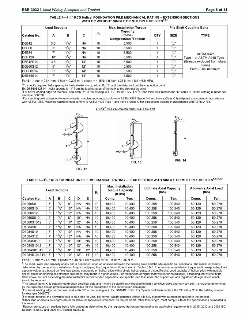
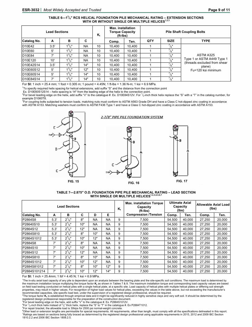
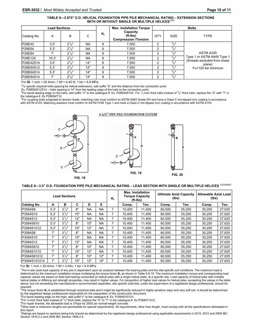
3.1.1 Leads and Extensions: The foundation pile lead section consists of a central steel shaft with one or more welded helical-shaped circular steel plates. The central steel shaft is either 11/2- or 13/4-inch (38.1 or 44.5 mm) Round Cornered Square (RCS) bar (D6 and D10, respectively) or 27/8-inch- or 31/2-inch-outside-diameter (73.0 or 88.9 mm) round steel pipe (P28 and P35, respectively) having a wall thickness of 0.203 inch or 0.216 inch (5.15 or 5.48 mm), respectively. The lead end is cut at an angle of 45 ± 5 degrees. (See Figures 9, 12, 15 and 18.)
The helices are helical-shaped circular steel plates made from either 3/8- or 1/2-inch-thick (9.5 or 12.7 mm) steel plate with 8-, 10-, 12- or 14-inch diameters (203, 254, 305 or 356 mm). Each helix is split from the center to the outside edge and formed into a clockwise downward spiral with all radial sections normal to the shaft’s central longitudinal axis, +/-3 degrees and with a 3-inch (76 mm) pitch. The pitch is the distance between the leading and trailing edge. The helix plate is then factory-welded to the steel shaft with the smallest helix in the lead and each succeeding helix spaced three times the diameter of the previous helix. After fabrication, the helical steel pile is hot-dipped galvanized in accordance with ASTM A123.
Each lead section of a helical foundation pile has provisions at the top end for a connection to an extension, and has an earth-penetrating pilot at the bottom end. Each extension has provisions for a coupling (male end) at one end and a connection (female end) at the other end.
The coupling for the RCS extension and extension-with-helix piles is an integrally forged socket that slips over an RCS shaft of the same size. Each socket has a transverse hole to join lead or extension sections with a bolt and a matching nut (See Figures 10, 11, 13, and 14.).
The lead section of the pipe pile has a female steel coupling factory-welded to the upper end. The extension has a matching male and female steel coupling welded at each end of the pipe. Each coupling has two transverse holes 90 degrees apart, and each can be connected with two bolts and matching nuts. (See Figures 16, 17, 19 and 20.)
3.1.2 Foundation Attachments (Brackets):
3.1.2.1 Repair Bracket: A foundation repair bracket is used to support gravity loads from existing concrete foundations. The bracket is cast in one piece from ductile iron, complying with ASTM A536, having minimum yield and tensile strengths of 45 and 65 ksi (310.3 and 448.2 MPa), respectively, and is hot-dipped galvanized in accordance with ASTM A153. The shelf of the bracket is placed underneath the foundation and measures 16.94 inches (430 mm) wide by 6.25 inches (159 mm) deep, with both corners chamfered 3.8 inches (97 mm). The shelf is 0.19 inch (4.83 mm) thick at the tip and tapered inward to a thickness of 0.731 inch (18.57 mm). The face of the bracket is bolted to the side of the concrete foundation and measures 16.75 inches (425 mm) wide by 8.25 inches (210 mm) deep by 0.312 inch (7.92 mm) thick. A lifting T-pipe and two 7/8-inch-diameter (22.2 mm) ASTM A325 threaded studs are used to lift the foundation via a

ESR-3032 | Most Widely Accepted and Trusted Page 2 of 11
lifting cylinder. The lifting T-pipe consists of a 1.75-inch (44 mm) round corner square steel bar 9.25 inches (235 mm) long welded to a 40-inch-long (1016 mm) steel pipe sized to accommodate the shaft type. The steel bar and steel pipe comply with the material properties shown in Section 3.2.2 of this report. (See Figures 5, 6, 7 and 8.)
3.1.2.2 New Construction Bracket: These brackets are used in new construction where the steel bearing plate of the bracket is cast into new concrete grade beam, footing or pile cap concrete foundations. The brackets can transfer compression, tension and lateral loads between the pile and the concrete foundation. The sleeve portion of the bracket, which is a one-piece steel casting complying with ASTM A958, Grade SC 1045, having minimum yield and tensile strengths of 40 and 80 ksi (275.8 and 551.6 MPa), respectively, is factory-welded to the cap plate. The cap plate is a steel plate 1/2 inch (12.7 mm) or 3/4 inch (19.1 mm) thick measuring 6 by 6 inches (152 mm) or 8 by 8 inches (203 mm) and complying with ASTM A36. The shaft connects to the bracket, as indicated in Table 1, with bolts conforming to Section 3.2.3.1. The bracket is hot-dipped galvanized in accordance with ASTM A153. (See Figures 1, 2, 3 and 4.)
3.2 Materials:
3.2.1 Helical Steel Plates: The helices are high-strength low-alloy steel per ASTM A1018 Grade 55, Class 1, with a minimum 55 ksi (379 MPa) yield strength and 65 ksi (450 MPa) tensile strength. The helical plates are factory-welded to the pile shafts.
3.2.2 Pile Shafts (Lead Sections and Extensions): The 11/2-inch (38 mm) RCS shafts are hot-wrought carbon steel conforming to ASTM A576, Grade 1045, with a minimum 70 ksi (482 MPa) yield strength and 100 ksi (689 MPa) tensile strength. The 13/4-inch (44.5 mm) RCS shaft is produced from steel conforming to ASTM A576, Grade 1530, with a minimum 90 ksi (621 MPa) yield strength and 120 ksi (827 MPa) tensile strength.
The 27/8- and 31/2-inch (73 and 88.9 mm) pipe shafts conform to ASTM A500, Grade C, with a minimum yield strength of 50 ksi (345 MPa) and a minimum tensile strength of 62 ksi (427 MPa). The couplings are made from cast steel conforming to ASTM A958, Grade SC 1045, having with a minimum 40 ksi (276 MPa) yield strength and 80 ksi (551 MPa) tensile strength.
3.2.3 Bolts:
3.2.3.1 Coupling and New Construction Bracket Bolts: The coupling bolts for leads and extensions and new construction bracket bolts are 3/4 inch (19.1 mm) or 7/8 inch (22.2 mm) in diameter, conform to ASTM A325 Type 1, or ASTM A449 Type 1, and have an ASTM A153, Class C, hot-dipped zinc coating installed with threads excluded from the shear plane. Unless otherwise noted in this report, matching nuts must conform to ASTM A563, Grade B, and have a Class C hot-dipped zinc coating conforming to ASTM 153. Matching washers (only used with back straps and lifting studs on repair bracket per Figures 5 and 6), must conform to ASME B18.22.1 and have a Class C hot-dipped zinc coating conforming to ASTM A153.
3.2.3.2 Repair Bracket Lifting Studs: The repair bracket lifting studs are two 7/8-inch-diameter (22.2 mm) fully threaded rods conforming to ASTM A325 material. The studs have a Class C hot-dipped zinc coating conforming to ASTM A153. Refer to Section 3.2.3.1 for matching nuts and washers.
3.2.3.3 Repair Bracket Securing Bolts: The bolts used to secure the lead or extension to the repair bracket are
1/2-inch-diameter (12.7 mm) bolts conforming to ASTM A325 Type I or ASTM A449 Type 1. The bolts have a Class C hot-dipped zinc coating conforming to ASTM A153. Refer to Section 3.2.3.1 for matching nuts and washers.
3.2.3.4 Concrete Anchor Bolts: Post-installed concrete anchor bolts used to secure the repair bracket to the side of the concrete foundation must be 5/8 inch (15.9 mm) in diameter with a minimum embedment of 4.5 inches (114 mm). The bolts must be recognized in ICC-ES evaluation report ESR-2526 or be an equivalent to the recognized bolts. The concrete anchor bolts must have a Class 55 mechanically deposited zinc coating conforming to ASTM B695.
4.0 DESIGN AND INSTALLATION
4.1 Design:
4.1.1 General:
Structural calculations and drawings, prepared by a registered design professional, must be submitted to the code official for each project; must be based on accepted engineering principles as described in IBC Section 1604.4; and must conform to 2015, 2012 and 2009 IBC Section 1810 and 2006 IBC Section 1808. The load capacities shown in this report are based on Allowable Strength Design method (ASD), described in IBC Section 1602 and AISC 360 Section B3.4. The structural analysis must consider all applicable internal forces (shear, bending moments and torsional moments, if applicable) due to applied loads, load transfer between the bracket and the pile segments (leads and extensions) and maximum span(s) between helical foundations. The result of the analysis and the structural capacities must be used to select a helical foundation system. The minimum embedment depth for various loading conditions must be included, based on the most stringent requirements of the following: engineering analysis; tested conditions described in this report; a site-specific geotechnical investigation report; and site-specific load tests, if applicable. For helical foundation systems subject to combined lateral and axial (compression or tension) loads, the allowable strength of the shaft under combined loads must be determined using the interaction equation prescribed in Chapter H of AISC 360.
A soil investigation report must be submitted to the code official as part of the required submittal documents, prescribed in Section 107 of the 2015, 2012 and 2009 IBC (2006 IBC Section 106), at the time of permit application. The soil investigation report must include, but is not limited to, all of the following:
1. A plot showing the location of the soil investigation.
2. A complete record of the soil boring and penetration test logs and soil samples.
3. A record of soil profile.
4. Information on groundwater table, frost depth and corrosion-related parameters, as described in Section 5.5 of this report.
5. Soil properties, including those affecting the design such as support conditions of the piles.
6. Soil design parameters, such as shear strength, soil bearing pressure, unit weight of soil, deformation characteristics and other parameters affecting pile support conditions as defined in 2015, 2012 and 2009 IBC Section 1803 and 2006 IBC Section 1808.2.2.
7. Confirmation of the suitability of helical foundation systems for the specific project.

ESR-3032 | Most Widely Accepted and Trusted Page 3 of 11
8. Recommendations for design criteria, including but not limited to mitigations of effects of differential settlement and varying soil strength; and effects of adjacent loads.
9. Recommended center-to-center spacing of helical pile foundations, if different from what is described in Section 5.14 of this report; and reduction of allowable loads due to group action, if necessary.
10. Field inspection and reporting procedures (to include procedures for verification of the installed bearing capacity, when required).
11. Load test requirements.
12. Any questionable soil characteristics and special design provisions, as necessary.
13. Expected total and differential settlement.
14. The axial compression, axial tension and lateral load soil capacities if values cannot be determined from this evaluation report.
The allowable axial compressive or tensile load of the helical pile system must be based on the least of the following in accordance with 2015, 2012 and 2009 IBC Section 1810.3.3.1.9:
Sum of the areas of the helical bearing plates affixed to the pile shaft times the ultimate bearing capacity of the soil or rock comprising the bearing stratum divided by a safety factor of 2. This capacity will be determined by a registered design professional based on site-specific conditions.
Allowable capacity determined from well-documented correlations with installation torque. Section 4.1.5 of this report includes torque correlation factors used to establish pile capacities based on documented correlations.
Allowable capacity from load tests. This capacity will be determined by a registered design professional for each site-specific condition.
Allowable axial capacity of pile shaft and pile shaft couplings. Section 4.1.3 of this report includes the smaller of pile shaft and shaft coupling capacities.
Sum of the allowable axial capacity of helical bearing plates affixed to the pile. Section 4.1.4 of this report includes helical plate axial capacities.
Allowable axial capacity of the bracket connecting to the foundation. Section 4.1.2 of this report includes bracket capacities.
4.1.2 Bracket Capacity: The concrete foundation must be designed and justified to the satisfaction of the building official with due consideration to the eccentricity of applied loads, including reactions provided by the brackets, acting on the concrete foundation. Only localized limit states of supporting concrete, including punching shear, and concrete bearing, have been evaluated in this evaluation report; other design aspects must be performed by a registered design professional. The effects of reduced lateral sliding resistance due to uplift from wind or seismic loads must be considered for each project. Table 1 provides the allowable compression loads of the new construction brackets. Table 2 provides the allowable compression loads for the repair brackets. Post-installed anchors used to secure the repair bracket to the foundation must be designed and installed in accordance with ESR-2526. Additional plates may be added to the bracket shelf to further distribute the load.
4.1.3 Pile Shaft Capacity: The top of the shafts must be braced as described in 2015, 2012 and 2009 IBC Section 1810.2.2 and 2006 IBC Section 1808.2.5. In accordance with 2015, 2012 and 2009 IBC Section 1810.2.1 and 2006 IBC Section 1808.2.9, any soil other than fluid soil must be deemed to afford sufficient lateral support to prevent buckling of the systems that are braced, and the unbraced length is defined as the length of piles standing in air, water, or fluid soils plus an additional 5 feet (1524 mm) when embedded into firm soil or an additional 10 feet (3048 mm) when embedded into soft soil. Firm soils must be defined as any soil with a Standard Penetration Test blow count of five or greater. Soft soils must be defined as any soil with a Standard Penetration Test blow count greater than zero and less than five. Fluid soils must be defined as any soil with a Standard Penetration Test blow count of zero [weight of hammer (WOH) or weight of rods (WOR)]. Standard Penetration Test blow count must be determined in accordance with ASTM D1586. For fully braced conditions where the pile is installed in accordance with 2015, 2012 and 2009 IBC Section 1810.2.2 and 2006 IBC Section 1808.2.5 and piles do not stand in air, water, or fluid soils, the allowable shaft capacities must not exceed the maximum design loads shown in Tables 3, 5, 7, and 9 for the D6, D10, P28, and P35 shafts, respectively. The shaft capacity of the helical foundation systems in air, water, or fluid soils must be determined by a registered design professional.
The elastic shortening/lengthening of the pile shaft will be based on the material and section properties of the shafts. The potential elastic shortening/lengthening at the allowable axial load is 0.00019, 0.00014, 0.00027, and 0.00021 inch per foot of shaft length per kip of axial load (0.0035, 0.0026, 0.005, and 0.004 millimeter per meter of shaft length per kilonewton of axial load) for the D6, D10, P28, and P35, respectively. Potential slip in couplers due to compression or tension is 0.082 inch per coupler at the rated allowable capacity for the D6, D10, P28, and P35 shaft couplers.
4.1.4 Helix Plate Capacity: Up to three helix plates can be placed on a single helical pile. The helix plates are spaced apart three times the diameter of the lowest plate, starting at the toe of the lead section. For helical piles with more than one helix, the allowable helix capacity for the helical foundation system may be taken as the sum of the least allowable capacity of each individual helix. The helix plate ASD capacities are shown in Table 12.
4.1.5 Soil Capacity: The allowable axial compressive or tensile soils capacity can be determined by site-specific soils investigation, as described in Section 4.1, combined with the individual helix bearing method (Method 1), or from field loading tests conducted under the supervision of a registered design professional (Method 2). For either Method 1 or Method 2, the predicted axial load capacities must be confirmed during the site-specific production installation, such that the axial load capacities predicted by the torque correlation method are equal to or greater than what is predicted by Method 1 or 2, described above. The individual bearing method is determined as the sum of the areas of the helical bearing plate times the ultimate bearing capacity of the soil or rock comprising the bearing stratum. The design allowable axial load must be determined by dividing the total ultimate axial load capacity predicted by either Method 1 or 2, above by a safety factor of at least 2. The torque correlation method must be used to determine the ultimate capacity (Qult) of the pile and the final installation torque (Equation 1). A factor of safety of 2 must be applied to the ultimate capacity to determine the allowable soil capacity (Qall) of the pile (Equation 2).

ESR-3032 | Most Widely Accepted and Trusted Page 4 of 11
Qult = Kt T (Equation 1)
Qall = 0.5 Qult (Equation 2)
where:
Kt = Torque correlation factor of 10 ft-1 (33 m-1) for the 1.5-inch- and 1.75-inch-square shafts; 9 ft-1 (30 m-1) for the 2.875-inch-outside-diameter round shaft; and 7 ft-1 (23 m-1) for the 3.5-inch-outside-diameter round shaft.
T = Final installation torque in ft-lbf or N-m. The final installation torque is defined as the average of the torque values recorded during each foot (305 mm) of installation over the final 3 feet (914 mm) of installation.
The lateral capacity of the piles referenced in Table 11 of this report is based on field testing of the 1.5- and 1.75- RCS and 2.875- and-3.5-inch-outside-diameter shafts with a single 8-inch-diameter helical plate installed in a very stiff clay soil having an average standard penetration blow count of 20, at a minimum embedment as indicated in Table 11. For soil condition other than very stiff clay, the lateral capacity of the pile must be designed by a registered design professional.
4.2 Installation:
The MacLean-Dixie Helical Foundation System is installed by factory-trained and certified installers. The helical foundation systems must be installed in accordance with this section (Section 4.2), 2015, 2012 and 2009 IBC Section 1810.4.11 and the manufacturer’s written installation instructions. In case of conflict, the more restrictive requirement governs.
4.2.1 Helical RCS and Pipe Piles: The helical piles must be installed and located in accordance with the approved plans and specifications. The foundation piles are typically installed using hydraulic rotary motors having forward and reverse capabilities. The torque rating (maximum installation torque capacity) for each of the included four steel pile shaft sizes is as shown in Tables 3 through 10 of this report. The foundation piles must be positioned and angled as specified in the approved plans. Helical piles attached to new construction brackets must be installed vertically plumb into the ground with ±1 degree of tolerance. Helical piles attached to repair brackets must be installed vertically plumb into the ground with ±3 degrees of tolerance. The foundation piles must be rotated clockwise in a continuous manner with the lead advancing at the helix pitch. The pile rotation rate is typically in the range of 5 to 20 revolutions per minute. Extensions (number and length) are selected based on the approved plans as specified per the site conditions by a registered design professional. The extensions and the foundation pile lead section must be connected by the coupling bolts. Coupling bolts must be snug-tightened as defined in Section J3 of AISC 360. The foundation piles are installed to the minimum depth shown on plans but with the top helix not less than 5 feet (1525 mm) below the bottom of the foundation. For tension application, the pile must be installed such that the minimum depth from the ground surface to the uppermost helix is 12D, where D is the diameter of the largest helix. All field-cut or drilled pilings must be protected from corrosion as recommended by the registered design professional.
4.2.2 Foundation Attachments:
4.2.2.1 Repair Bracket: The repair bracket must be installed as specified in the approved plans, by certified MPS Civil installers. The foundation must be excavated to create an “L” shaped cavity with a nominally 30-inch-wide opening and a nominal depth of 18 inches below the foundation bottom surface to access the foundation for the
bracket. The exposed foundation surfaces must be prepared to be flat and smoothly dressed to receive the repair bracket without obstruction on the bearing or facing surfaces. The bracket must be pinned firmly to the side of the foundation with six post-installed bolts complying with Section 3.2.3.4 of this report. Installation of the post-installed concrete anchor bolts must comply with ESR-2526. This connection may occur during or after helical foundation pile installation. The foundation pile lead and shaft extensions must be installed into soil as set forth in Section 4.2.1. When the pile is installed to the required depth, if the top of the extension is not within the required elevation, excess shaft extension above the foundation may be cut, nominally 8 to 10 inches above the footing. Attachment of the foundation repair bracket to the foundation pile shall be in accordance with the approved plans and must be designed by a registered design professional.
If the supporting structure will be lifted by the repair bracket, a connecting all-thread rod and nut are used to connect T-pipe and shaft together. A 3/4-inch-diameter (19.1 mm) all-thread rod is used on the D6 or P28 shaft, and 7/8-inch-diameter (22.2 mm) all-thread rod is used on the D10 or P35 shaft. Lifting of the structure must be verified by the registered design professional to ensure that the foundation and/or superstructure are not overstressed.
4.2.2.2 New Construction Bracket: New foundation brackets are placed on top of the helical piles. The top of the lead or extension may be cut off to level as required. The embedment and edge distance of the bracket into the concrete foundation must be as described in the approved plans and this report. The concrete foundation is cast around the bracket.
4.3 Special Inspection:
Continuous special inspection in accordance with 2015 and 2012 IBC Section 1705.9, 2009 IBC Section 1704.10, and 2006 IBC Section 1704.9 must be provided for the installation of the foundation piles and foundation brackets. Where on-site welding is required, inspection in accordance with 2015 and 2012 IBC Section 1705.2 and 2009 and 2006 IBC Section 1704.3 is also required. Items to be confirmed by the special inspector include (but are not limited to) the manufacturer’s certification of installers, verification of the product manufacturer, helical pile and bracket configuration and identification, inclination and position of helical piles, the installation torque and depth of the foundation piles, and compliance of the installation with the approved construction documents and this evaluation report.
5.0 CONDITIONS OF USE
The MacLean-Dixie Helical Foundation Systems described in this report comply with, or are suitable alternatives to what is specified in, the code indicated in Section 1.0 of this report, subject to the following conditions:
5.1 The helical foundation systems are manufactured, identified and installed in accordance with this report, the manufacturer’s written installation instructions and the approved construction documents. In the event of a conflict, the most restrictive requirement governs.
5.2 Helical foundation systems have been evaluated to support structures in Seismic Design Categories (SDCs) A, B and C. Use of the systems to support structures assigned to Seismic Design Category D, E, or F or which are located in Site Class E or F are outside the scope of this report and are subject to the approval of the building official, based upon

ESR-3032 | Most Widely Accepted and Trusted Page 5 of 11
submission of a design in accordance with the code by a registered design professional.
5.3 Both the repair bracket and the new construction bracket must be used only to support structures that are laterally braced as defined in 2015, 2012 and 2009 IBC Section 1810.2.2 and 2006 IBC Section 1808.2.5.
5.4 Installation of repair and new construction brackets is limited to regions of concrete members where analysis indicates no cracking at service load levels.
5.5 Use of the helical foundation systems in exposure conditions that are indicative of potential pile deterioration or corrosion situations as defined by the following: (1) soil resistivity less than 1,000 ohm-cm; (2) soil pH less than 5.5; (3) soils with high organic content; (4) soil sulfate concentrations greater than 1,000 ppm; (5) soils located in landfill; or (6) soil containing mine waste is beyond the scope of the evaluation report.
5.6 Zinc-coated steel and bare steel components must not be combined in the same system. All helical foundation components must be galvanically isolated from concrete reinforcing steel, building structural steel, or any other metal building components.
5.7 The permitted inclination of the helical piles must not exceed the provisions indicated in Section 4.2.1 of this report. To comply with the requirements found in Section 1810.3.1.3 of the 2015, 2012 and 2009 IBC (Section 1808.2.8.8 of the 2006 IBC), the superstructure must be designed to resist the effects of helical pile eccentricity.
5.8 Engineering calculations and drawings in accordance with recognized engineering principles, as described in IBC Section 1604.4 and in compliance with Section 4.1 of this report, are prepared by a registered design professional, and reviewed and approved by the code official.
5.9 The adequacy of the concrete structures that are connected to the brackets must be verified by a registered design professional in accordance with applicable code provisions, such as Chapter 13 of ACI 318-14 under the 2015 IBC (Chapter 15 of ACI 318 under the 2012, 2009 and 2006 IBC) and Chapter 18 of IBC. Adequacy is subject to the approval of the code official.
5.10 A geotechnical investigation report in accordance with Section 4.1.1 of this report must be submitted to the code official.
5.11 Special inspection is provided in accordance with Section 4.3 of this report.
5.12 The load combinations prescribed in either Section 1605.3.1 or Section 1605.3.2 of the IBC must be used to determine the applied loads. When using the alternative basic load combinations prescribed in Section 1605.3.2, the allowable stress increases permitted by material chapters of the IBC or the referenced standards are prohibited.
5.13 The applied loads must not exceed the allowable capacities described in Section 4.1 of this report.
5.14 In order to avoid group efficiency effects, an analysis prepared by a registered design professional must be submitted where the center-to-center spacing of axially loaded helical piles is less than three times the diameter of the largest helix plate at the depth of bearing. An analysis prepared by a registered design professional must also be submitted where the center-to-center spacing of laterally loaded helical piles is less than eight times the least horizontal dimension of the pile shaft at the ground surface; and the spacing between helical piles must not be less than 3D, where D is the diameter of the largest helical plate measured from the edge of the helical plate to the edge of the helical plate adjacent; or 4D, where the spacing is measured from center-to-center of the adjacent helical pile.
5.15 Connection of the brackets as it relates to seismic forces and the provisions found in 2015, 2012 and 2009 IBC Sections 1810.3.11.1 and 1810.3.6.1 and 2006 IBC Section 1808.2.23.1, for buildings assigned to Seismic Design Category C, and for all buildings under the 2015, 2012 and 2009 IBC Section 1810.3.6 (second paragraph) and 2006 IBC Section 1808.2.7, are outside the scope of this report.
5.16 Settlement of the helical pile is outside the scope of this evaluation report and must be determined by a registered design professional, as required in 2015, 2012 and 2009 IBC Section 1810.2.3 and 2006 IBC Section 1808.2.12.
5.17 Post-installed anchors, including requirements for installation and inspection, must comply with the applicable ICC-ES evaluation reports described in Section 3.2.3.4 of this report.
5.18 Installation must be performed by contractors certified by MacLean Power Systems Civil Products.
5.19 The helical foundation systems are manufactured at the MacLean Power Systems Civil Products Trenton, Tennessee facility located at 1465 Industrial Park Drive, Trenton, Tennessee, under a quality-control program with inspections by ICC-ES.
6.0 EVIDENCE SUBMITTED
Data in accordance with the ICC-ES Acceptance Criteria for Helical Pile Systems and Devices (AC358), dated September 2017.
7.0 IDENTIFICATION (ESR-3032 product lines only)
Foundation piles have a “D” stamped on the RCS shaft and have the letters “MPS” on the coupling for pipe piles. The foundation piles are also identified by a tag or label bearing the MacLean Power Systems Civil Products (MPS Civil Products) name and address, the catalog number, the product description, and the evaluation report number (ESR-3032). The repair bracket is marked “Dixie350H,” and the new construction bracket has the letters “MPS” on the steel casting with “CPL287M” for D6 and P28 shafts and “CPL350M” for D10 and P35 shafts.
ESR-3032 | Most Widely Accepted and Trusted Page 6 of 11
TABLE 1—ALLOWABLE CAPACITY FOR NEW CONSTRUCTION BRACKETS FOR RCS FOUNDATION & PIPE PILES5,6
BRACKETS Figure
Allowable Compressive/Tension Load for
11/2″ RCS (lbs)1
Allowable Compressive/Tension
Load for 13/4″ RCS (lbs)2
Allowable Compressive/Tension
Load for P28 (lbs)3
Allowable Compressive/Tension
Load for P35 (lbs)4 Catalog No. W L T
NCB060604CP1 6″ 6″ 1/2″ 3 25,600 N/A N/A N/A
NCB080806CP2 8″ 8″ 3/4″ 3 N/A 35,000 N/A N/A
NCB060604CP1B 6″ 6″ 1/2″ 3 N/A N/A 30,000 N/A
NCB080806CP2B 8″ 8″ 3/4″ 3 N/A N/A N/A 40,000
For SI: 1 inch = 25.4 mm; 1 lbf = 4.45 N; 1 ksi = 6.9 MPa. N/A = not applicable. 111/2″ RCS uses one 0.75-inch diameter ASTM A325 Type I or ASTM A449 Type 1 bolt, where threads are excluded from the shear plane. Allowable compressive load value is based on that the installed embedment of the bracket is 8.6 inches measured from the top of the concrete foundation to the top of the bracket steel plate. Allowable tension load value is based on that the installed embedment of the bracket is 10.6 inches measured from the bottom of the concrete foundation to the top of the bracket steel plate. See note 5 below for more detail regarding the minimum width of the concrete foundation, edge distance, and load conditions. 213/4″ RCS uses one 0.875-inch diameter ASTM A325 Type I or ASTM A449 Type 1bolt, where threads are excluded from the shear plane. Allowable load value is based on that the installed embedment of the bracket is 9.7 inches measured from the top of the concrete foundation to the top of the bracket steel plate. Allowable tension load value is based on that the installed embedment of the bracket is 11.7 inches measured from the bottom of the concrete foundation to the top of the bracket steel plate. See note 5 below for more detail regarding the minimum width of the concrete foundation, edge distance, and load conditions. 32.875-inch (P28) outside diameter pile shaft uses two 0.75-inch diameter ASTM A325 Type I or ASTM A449 Type 1bolt, where threads are excluded from the shear plane. Allowable load value is based on that the installed embedment of the bracket is 11 inches measured from the top of the concrete foundation to the top of the bracket steel plate. Allowable tension load value is based on that the installed embedment of the bracket is 13 inches measured from the bottom of the concrete foundation to the top of the bracket steel plate. See note 5 below for more detail regarding the minimum width of the concrete foundation, edge distance, and load conditions. 43.5-inch (P35) outside diameter pile shaft uses two 0.875-inch diameter ASTM A325 Type I or ASTM A449 Type 1 bolt, where threads are excluded from the shear plane. Allowable load value is based on that the installed embedment of the bracket is 15 inches measured from the top of the concrete foundation to the top of the bracket steel plate. Allowable tension load value is based on that the installed embedment of the bracket is 15 inches measured from the bottom of the concrete foundation to the top of the bracket steel plate. See note 5 below for more detail regarding the minimum width of the concrete foundation, edge distance, and load conditions. 5The minimum width of the concrete foundation is 14 inches. Minimum concrete cover measured from the bottom of the concrete foundation to the bottom of the bracket steel plate is 3 inches. Minimum edge distance of 4 inches is required measured from the edge of the concrete foundation to the edge of the steel plate. The allowable load values shown above are based on limit states associate with punching shear and concrete bearing capacity of the brackets installed in structural plain concrete with two-way action. Localized limit states for steel components are also considered. For other limit states, the bracket capacity must be determined by a registered design professional. The allowable capacities are based on installation with normal-weight concrete having a minimum 28-day compressive strength of 2500 psi. The capacities assume the pile supported structure is sideways braced per 2015, 2012 and 2009 IBC Section 1810.2.2 and 2006 IBC Section 1808.2.5. 6Matching nuts must conform to ASTM A563 Grade DH and have a Class C hot-dipped zinc coating in accordance with ASTM A153. Matching washers must conform to ASTM F436 Type 1 and have a Class C hot-dipped zinc coating in accordance with ASTM A153.
FIGURE 1 FIGURE 2
FIGURE 3
FIGURE 4
FIGURE 5 FIGURE 6 FIGURE 7 FIGURE 8

ESR-3032 | Most Widely Accepted and Trusted Page 7 of 11
TABLE 2—ALLOWABLE CAPACITY FOR FOUNDATION REPAIR BRACKET FOR RCS & PIPE PILES1.2
Brackets Figure Compatible w/ Allowable Compression Load (kips)
Dixie350-B4 6 & 8 11/2″ RCS 24
Dixie350-B5 6 & 7 13/4″ RCS 38.5
Dixie350-B6 6 & 7 P28 Pipe 30
Dixie350-B7 6 & 7 P35 Pipe 37
For SI: 1 inch = 25.4 mm; 1 kip = 1000 lbf = 4.45 kN. 1Load capacity is based on full scale load tests per AC358 with the installed T-pipe placed over the pile shaft. The bracket is placed under a 2500 psi normal-weight concrete foundation with six post-installed anchor bolts fastened through the face of the bracket into the side of the foundation. Installation of anchor bolts must be at pre-drilled hole locations on the face of the bracket in accordance with Section 4.2.1 of this report. See Figures 5 and 6. 2 The capacities assume the pile supported structure is sidesway braced per 2015, 2012 and 2009 IBC Section 1810.2.2 and 2006 IBC Section 1808.2.5.
TABLE 3—11/2″ RCS FOUNDATION PILE MECHANICAL RATING – LEAD SECTION WITH SINGLE OR MULTIPLE HELICES1,2,3,4,5,6
Lead Sections Kt
Max. Installation Torque Capacity
(ft-lbs) Compression/Tension
Ultimate Axial Capacity (lbs)
Allowable Axial Load (lbs)
Catalog No. A B C D E Comp. Ten. Comp. Ten.
D660S8 5′ 11/2″ 8″ NA NA 10 5,500 55,000 37,000 27,500 18,500
D660S10 5′ 11/2″ 10″ NA NA 10 5,500 55,000 37,000 27,500 18,500
D660S12 5′ 11/2″ 12″ NA NA 10 5,500 55,000 37,000 27,500 18,500
D660S810 5′ 11/2″ 8″ 10″ NA 10 5,500 55,000 37,000 27,500 18,500
D660S1012 5′ 11/2″ 10″ 12″ NA 10 5,500 55,000 37,000 27,500 18,500
D684S8 7′ 11/2″ 8″ NA NA 10 5,500 55,000 37,000 27,500 18,500
D684S10 7′ 11/2″ 10″ NA NA 10 5,500 55,000 37,000 27,500 18,500
D684S12 7′ 11/2″ 12″ NA NA 10 5,500 55,000 37,000 27,500 18,500
D684S810 7′ 11/2″ 8″ 10″ NA 10 5,500 55,000 37,000 27,500 18,500
D684S1012 7′ 11/2″ 10″ 12″ NA 10 5,500 55,000 37,000 27,500 18,500
D684S81012 7′ 11/2″ 8″ 10″ 12″ 10 5,500 55,000 37,000 27,500 18,500
D684S101214 7′ 11/2″ 10″ 12″ 14″ 10 5,500 55,000 37,000 27,500 18,500
For SI: 1 inch = 25.4 mm; 1 pound = 0.00448 KN; 1 ksi = 6.985 Mpa. 1The in-situ axial load capacity of any pile is dependent upon an analysis between the bearing plate and the site-specific soil conditions. The maximum load is determined by the maximum installation torque multiplying the torque factor Kt. as shown in Tables 3 & 4. The maximum installation torque and corresponding load capacity values are based on field load testing conducted on helical piles with a single helical plate, at a specific site. Load capacity of helical piles with multiple helical plates or differing soil strength properties, may result in higher values. For recognition of higher load values for helical piles, exceeding the values in the table above, but not exceeding the manufacturer’s recommended capacities, site specific load test, under the supervision of a registered design professional, should be required. 2The torque factor Kt. is established through empirical data and it might be significantly reduced in highly sensitive clays and very soft soil. It should be determined by the registered design professional responsible for the preparation of the construction document. 3For bevel leading edge on the helix, add suffix “V” to the catalogue #. Ex. D684S1012V. For ½-inch thick helix replace the “S” with a “T” in the catalog number, for example D660T8. 4For repair bracket, the allowable compression load is 24 kips for 2500 psi normal-weight concrete unless it is fully braced without rotation applied to the bracket. 5Other lead or extension lengths are permissible for special requirements. All requirements, other than length, must comply with all the specifications delineated in this report. 6Ratings are based on sections being fully braced as determined by the registered design professional using applicable requirements in 2015, 2012 and 2009 IBC Section 1810.2.2 and 2006 IBC Section 1808.2.5.
FIGURE 9
FIGURE 10FIGURE 11
ESR-3032 | Most Widely Accepted and Trusted Page 8 of 11
TABLE 4—11/2″ RCS Helical FOUNDATION PILE MECHANICAL RATING – EXTENSION SECTIONS WITH OR WITHOUT SINGLE OR MULTIPLE HELICES1,2,3
Lead Sections
Kt
Max. installation Torque Capacity (ft-lbs)
Compression /Tension
Pile Shaft Coupling Bolts
Catalog No. A B C QTY SIZE TYPE
D6E42 3.5′ 11/2″ NA 10 5,500 1 3/4″
ASTM A325
Type 1 or ASTM A449 Type 1(threads excluded from shear
plane) Fu=120 ksi minimum
D6E60 5′ 11/2″ NA 10 5,500 1 3/4″
D6E84 7′ 11/2″ NA 10 5,500 1 3/4″
D6E120 10′ 11/2″ NA 10 5,500 1 3/4″
D6E42S14 3.5′ 11/2″ 14″ 10 5,500 1 3/4″
D6E60S12 5′ 11/2″ 12″ 10 5,500 1 3/4″
D6E60S14 5′ 11/2″ 14″ 10 5,500 1 3/4″
D6E84S14 7′ 11/2″ 14″ 10 5,500 1 3/4″
For SI: 1 inch = 25.4 mm; 1 foot = 0.305 m; 1 pound = 4.45N; 1 ft-lbs= 1.36 N-m; 1 ksi = 6.9 MPa. 1To specify required helix spacing for helical extensions, add suffix “S” and the distance from the connection point. Ex. D6E60S12S14 – helix spacing is 14″ from the leading edge of the helix to the connection point. 2For bevel leading edge on the helix, add suffix “V” to the catalogue #. Ex. D6E84S12V. For 1/2-inch thick helix replace the “S” with a “T” in the catalog number, for example D660T8. 3For coupling bolts subjected to tension loads, matching nuts must conform to ASTM A563 Grade DH and have a Class C hot-dipped zinc coating in accordance with ASTM A153. Matching washers must confirm to ASTM F436 Type 1 and have a Class C hot-dipped zinc coating in accordance with ASTM A153.
TABLE 5—13/4″ RCS FOUNDATION PILE MECHANICAL RATING – LEAD SECTION WITH SINGLE OR MULTIPLE HELICES1,2,3,4,5,6
Lead Sections Kt
Max. Installation Torque Capacity
(ft-lbs)
Ultimate Axial Capacity (lbs)
Allowable Axial Load (lbs)
Catalog No. A B C D E Comp. Ten. Comp. Ten. Comp. Ten.
D1060S8 5′ 13/4″ 8″ NA NA 10 10,400 10,400 100,258 100,540 50,129 50,270
D1060S10 5′ 13/4″ 10″ NA NA 10 10,400 10,400 100,258 100,540 50,129 50,270
D1060S12 5′ 13/4″ 12″ NA NA 10 10,400 10,400 100,258 100,540 50,129 50,270
D1060S810 5′ 13/4″ 8″ 10″ NA 10 10,400 10,400 100,258 100,540 50,129 50,270
D1060S1012 5′ 13/4″ 10″ 12″ NA 10 10,400 10,400 100,258 100,540 50,129 50,270
D1084S8 7′ 13/4″ 8″ NA NA 10 10,400 10,400 100,258 100,540 50,129 50,270
D1084S10 7′ 13/4″ 10″ NA NA 10 10,400 10,400 100,258 100,540 50,129 50,270
D1084S12 7′ 13/4″ 12″ NA NA 10 10,400 10,400 100,258 100,540 50,129 50,270
D1084S810 7′ 13/4″ 8″ 10″ NA 10 10,400 10,400 100,258 100,540 50,129 50,270
D1084S1012 7′ 13/4″ 10″ 12″ NA 10 10,400 10,400 100,258 100,540 50,129 50,270
D1084S81012 7′ 13/4″ 8″ 10″ 12″ 10 10,400 10,400 100,258 100,540 50,129 50,270
D1084S101214 7′ 13/4″ 10″ 12″ 14″ 10 10,400 10,400 100,258 100,540 50,129 50,270
For SI: 1 inch = 25.4 mm; 1 pound = 4.45 N; 1 ksi = 6.985 MPa; 1 ft-lbf = 1.36 N-m. 1The in-situ axial load capacity of any pile is dependent upon an analysis between the bearing plate and the site-specific soil conditions. The maximum load is determined by the maximum installation torque multiplying the torque factor Kt. as shown in Tables 5 & 6. The maximum installation torque and corresponding load capacity values are based on field load testing conducted on helical piles with a single helical plate, at a specific site. Load capacity of helical piles with multiple helical plates or differing soil strength properties, may result in higher values. For recognition of higher load values for helical piles, exceeding the values in the table above, but not exceeding the manufacturer’s recommended capacities, site specific load test, under the supervision of a registered design professional, should be required. 2The torque factor Kt. is established through empirical data and it might be significantly reduced in highly sensitive clays and very soft soil. It should be determined by the registered design professional responsible for the preparation of the construction document. 3For bevel leading edge on the helix, add suffix ”V” to the catalogue #. Ex. D1084S1012V. For 1/2-inch thick helix replace the “S” with a “T” in the catalog number, for example D1060T8. 4For repair bracket, the allowable load is 38.5 kips for 2500 psi normal-weight concrete unless it is fully braced without rotation applied to the bracket. 5Other lead or extension lengths are permissible for special requirements. All requirements, other than length, must comply with all the specifications delineated in this report. 6Ratings are based on sections being fully braced as determined by the registered design professional using applicable requirements in 2015, 2012 and 2009 IBC Section 1810.2.2 and 2006 IBC Section 1808.2.5.
FIG. 12
FIG. 13 FIG. 14
ESR-3032 | Most Widely Accepted and Trusted Page 9 of 11
TABLE 6—13/4″ RCS HELICAL FOUNDATION PILE MECHANICAL RATING – EXTENSION SECTIONS WITH OR WITHOUT SINGLE OR MULTIPLE HELICES1,2,3
Lead Sections Kt
Max. installation Torque Capacity
(ft-lbs) Pile Shaft Coupling Bolts
Catalog No. A B C Comp. Ten. QTY SIZE TYPE
D10E42 3.5′ 13/4″ NA 10 10,400 10,400 1 7/8″
ASTM A325 Type 1 or ASTM A449 Type 1 (threads excluded from shear
plane) Fu=120 ksi minimum
D10E60 5′ 13/4″ NA 10 10,400 10,400 1 7/8″
D10E84 7′ 13/4″ NA 10 10,400 10,400 1 7/8″
D10E120 10′ 13/4″ NA 10 10,400 10,400 1 7/8″
D10E42S14 3.5′ 13/4″ 14″ 10 10,400 10,400 1 7/8″
D10E60S12 5′ 13/4″ 12″ 10 10,400 10,400 1 7/8″
D10E60S14 5′ 13/4″ 14″ 10 10,400 10,400 1 7/8″
D10E84S14 7′ 13/4″ 14″ 10 10,400 10,400 1 7/8″
For SI: 1 inch = 25.4 mm; 1 foot = 0.305 m; 1 pound = 4.45N; 1 ft-lbs = 1.36 N-m; 1 ksi = 6.9 MPa. 1To specify required helix spacing for helical extensions, add suffix “S” and the distance from the connection point Ex. D10E60S12S14 – helix spacing is 14″ from the leading edge of the helix to the connection point. 2For bevel leading edge on the helix, add suffix “V” to the catalogue #. Ex. D10E84S12V. For 1/2-inch thick helix replace the “S” with a “T” in the catalog number, for example D1060T8. 3For coupling bolts subjected to tension loads, matching nuts must conform to ASTM A563 Grade DH and have a Class C hot-dipped zinc coating in accordance with ASTM A153. Matching washers must confirm to ASTM F436 Type 1 and have a Class C hot-dipped zinc coating in accordance with ASTM A153.
TABLE 7—2.875″ O.D. FOUNDATION PIPE PILE MECHANICAL RATING – LEAD SECTION WITH SINGLE OR MULTIPLE HELICES1,2,3,4,5,6,7
Lead Sections Kt
Max. installation Torque Capacity (ft-lbs)
Compression /Tension
Ultimate Axial Capacity
(lbs)
Allowable Axial Load(lbs)
Catalog No. A B C D E Comp. Ten. Comp. Ten.
P2864S8 5.3′ 27/8″ 8″ NA NA 9 7,500 54,500 40,000 27,250 20,000
P28640S10 5.3′ 27/8″ 10″ NA NA 9 7,500 54,500 40,000 27,250 20,000
P2864S12 5.3′ 27/8″ 12″ NA NA 9 7,500 54,500 40,000 27,250 20,000
P2864S810 5.3′ 27/8″ 8″ 10″ NA 9 7,500 54,500 40,000 27,250 20,000
P2864S1012 5.3′ 27/8″ 10″ 12″ NA 9 7,500 54,500 40,000 27,250 20,000
P2884S8 7′ 27/8″ 8″ NA NA 9 7,500 54,500 40,000 27,250 20,000
P2884S10 7′ 27/8″ 10″ NA NA 9 7,500 54,500 40,000 27,250 20,000
P2884S12 7′ 27/8″ 12″ NA NA 9 7,500 54,500 40,000 27,250 20,000
P2884S810 7′ 27/8″ 8″ 10″ NA 9 7,500 54,500 40,000 27,250 20,000
P2884S1012 7′ 27/8″ 10″ 12″ NA 9 7,500 54,500 40,000 27,250 20,000
P2884S81012 7′ 27/8″ 8″ 10″ 12″ 9 7,500 54,500 40,000 27,250 20,000
P2884S101214 7′ 27/8″ 10″ 12″ 14″ 9 7,500 54,500 40,000 27,250 20,000
For SI: 1 inch = 25.4mm; 1 lbf = 4.45 N; 1 ksi = 6.9 MPa. 1The in-situ axial load capacity of any pile is dependent upon an analysis between the bearing plate and the site-specific soil conditions. The maximum load is determined by the maximum installation torque multiplying the torque factor Kt. as shown in Tables 7 & 8. The maximum installation torque and corresponding load capacity values are based on field load testing conducted on helical piles with a single helical plate, at a specific site. Load capacity of helical piles with multiple helical plates or differing soil strength properties, may result in higher values. For recognition of higher load values for helical piles, exceeding the values in the table above, but not exceeding the manufacturer’s recommended capacities, site specific load test, under the supervision of a registered design professional, should be required. 2The torque factor Kt. is established through empirical data and it might be significantly reduced in highly sensitive clays and very soft soil. It should be determined by the registered design professional responsible for the preparation of the construction document. 3For bevel leading edge on the helix, add suffix “V” to the catalogue #. Ex. P2884S1012V. 4For 1/2-inch thick helix instead of 3/8″ thick helix, replace the “S” to “T” in the catalogue #. Ex P2884T1012. 5For repair bracket, the allowable load is 30kips for 2500 psi normal-weight concrete. 6Other lead or extension lengths are permissible for special requirements. All requirements, other than length, must comply with all the specifications delineated in this report. 7Ratings are based on sections being fully braced as determined by the registered design professional using applicable requirements in 2015, 2012 and 2009 IBC Section 1810.2.2 and 2006 IBC Section 1808.2.5.
FIG. 15 FIG. 16 FIG. 17
ESR-3032 | Most Widely Accepted and Trusted Page 10 of 11
TABLE 8—2.875″ O.D. HELICAL FOUNDATION PIPE PILE MECHANICAL RATING – EXTENSION SECTIONS WITH OR WITHOUT SINGLE OR MULTIPLE HELICES1,2,3
Lead Sections
Kt
Max. installation Torque Capacity (ft-lbs)
Compression /Tension
Bolts
Catalog No. A B C QTY SIZE TYPE
P28E42 3.5′ 27/8″ NA 9 7,500 2 3/4″
ASTM A325 Type 1 or ASTM A449 Type 1 (threads excluded from shear
plane) Fu=120 ksi minimum
P28E64 5.3′ 27/8″ NA 9 7,500 2 3/4″
P28E84 7′ 27/8″ NA 9 7,500 2 3/4″
P28E124 10.3′ 27/8″ NA 9 7,500 2 3/4″
P28E42S14 3.5′ 27/8″ 14″ 9 7,500 2 3/4″
P28E64S12 5.3′ 27/8″ 12″ 9 7,500 2 3/4″
P28E64S14 5.3′ 27/8″ 14″ 9 7,500 2 3/4″
P28E84S14 7′ 27/8″ 14″ 9 7,500 2 3/4″
For SI: 1 inch = 25.4mm; 1 lbf = 4.45 N; 1 ksi = 6.9 MPa. 1To specify required helix spacing for helical extensions, add suffix “S” and the distance from the connection point. Ex. P28E64S12S14 – helix spacing is 14″ from the leading edge of the helix to the connection point. 2For bevel leading edge on the helix, add suffix “V” to the catalogue #. Ex. P28E84S10V. For 1/2-inch thick helix instead of 3/8″-thick helix, replace the “S” with “T” in the catalogue #. Ex P28E84T12. 3For coupling bolts subjected to tension loads, matching nuts must conform to ASTM A563 Grade DH and have a Class C hot-dipped zinc coating in accordance with ASTM A153. Matching washers must confirm to ASTM F436 Type 1 and have a Class C hot-dipped zinc coating in accordance with ASTM A153.
TABLE 9—3.5″ O.D. FOUNDATION PIPE PILE MECHANICAL RATING – LEAD SECTION WITH SINGLE OR MULTIPLE HELICES 1,2,3,4,5,6,7
Lead Sections Kt
Max. Installation Torque Capacity
(ft-lbs)
Ultimate Axial Capacity (lbs)
Allowable Axial Load(lbs)
Catalog No. A B C D E Comp. Ten. Comp. Ten. Comp. Ten.
P3564S8 5.3′ 31/2″ 8″ NA NA 7 10,400 11,400 60,500 55,250 30,250 27,625
P3564S10 5.3′ 31/2″ 10″ NA NA 7 10,400 11,400 60,500 55,250 30,250 27,625
P3564S12 5.3′ 31/2″ 12″ NA NA 7 10,400 11,400 60,500 55,250 30,250 27,625
P3564S810 5.3′ 31/2″ 8″ 10″ NA 7 10,400 11,400 60,500 55,250 30,250 27,625
P3564S1012 5.3′ 31/2″ 10″ 12″ NA 7 10,400 11,400 60,500 55,250 30,250 27,625
P3584S8 7′ 31/2″ 8″ NA NA 7 10,400 11,400 60,500 55,250 30,250 27,625
P3584S10 7′ 31/2″ 10″ NA NA 7 10,400 11,400 60,500 55,250 30,250 27,625
P3584S12 7′ 31/2″ 12″ NA NA 7 10,400 11,400 60,500 55,250 30,250 27,625
P3584S810 7′ 31/2″ 8″ 10″ NA 7 10,400 11,400 60,500 55,250 30,250 27,625
P3584S1012 7′ 31/2″ 10″ 12″ NA 7 10,400 11,400 60,500 55,250 30,250 27,625
P3584S81012 7′ 31/2″ 8″ 10″ 12″ 7 10,400 11,400 60,500 55,250 30,250 27,625
P3584S101214 7′ 31/2″ 10″ 12″ 14″ 7 10,400 11,400 60,500 55,250 30,250 27,625
For SI: 1 inch = 25.4mm; 1 lbf = 4.45n; 1 ksi = 6.9 MPa. 1The in-situ axial load capacity of any pile is dependent upon an analysis between the bearing plate and the site-specific soil conditions. The maximum load is determined by the maximum installation torque multiplying the torque factor Kt. as shown in Table 9 & 10. The maximum installation torque and corresponding load capacity values are based on field load testing conducted on helical piles with a single helical plate, at a specific site. Load capacity of helical piles with multiple helical plates or differing soil strength properties, may result in higher values. For recognition of higher load values for helical piles, exceeding the values in the table above, but not exceeding the manufacturer’s recommended capacities, site specific load test, under the supervision of a registered design professional, should be required. 2The torque factor Kt. is established through empirical data and it might be significantly reduced in highly sensitive clays and very soft soil. It should be determined by the registered design professional responsible for the preparation of the construction document. 3For bevel leading edge on the helix, add suffix“V” to the catalogue #. Ex. P3584S1012V. 4For ½-inch thick helix instead of 3/8″ thick helix, replace the “S” to “T” in the catalogue #. Ex P3584T1012. 5For repair bracket, the allowable load is 37kips for 2500 psi normal-weight concrete. 6Other lead or extension lengths are permissible for special requirements. All requirements, other than length, must comply with all the specifications delineated in this report. 7Ratings are based on sections being fully braced as determined by the registered design professional using applicable requirements in 2015, 2012 and 2009 IBC Section 1810.2.2 and 2006 IBC Section 1808.2.5.
FIG. 18
FIG. 19 FIG. 20
ESR-3032 | Most Widely Accepted and Trusted Page 11 of 11
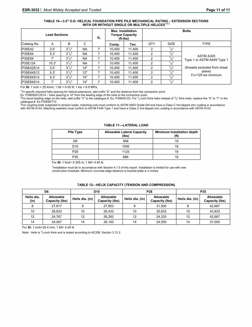
TABLE 10—3.5″ O.D. HELICAL FOUNDATION PIPE PILE MECHANICAL RATING – EXTENSION SECTIONS
WITH OR WITHOUT SINGLE OR MULTIPLE HELICES1,2,3
Lead Sections Kt
Max. installation Torque Capacity
(ft-lbs)
Bolts
Catalog No. A B C Comp. Ten. QTY SIZE TYPE
P35E42 3.5′ 31/2″ NA 7 10,400 11,400 2 7/8″
ASTM A325 Type 1 or ASTM A449 Type 1
(threads excluded from shear
plane) Fu=120 ksi minimum
P35E64 5.3′ 31/2″ NA 7 10,400 11,400 2 7/8″
P35E84 7′ 31/2″ NA 7 10,400 11,400 2 7/8″
P35E124 10.3′ 31/2″ NA 7 10,400 11,400 2 7/8″
P35E42S14 3.5′ 31/2″ 14″ 7 10,400 11,400 2 7/8″
P35E64S12 5.3′ 31/2″ 12″ 7 10,400 11,400 2 7/8″
P35E64S14 5.3′ 31/2″ 14″ 7 10,400 11,400 2 7/8″
P35E84S14 7′ 31/2″ 14″ 7 10,400 11,400 2 7/8″
For SI: 1 inch = 25.4mm; 1 lbf = 4.45 N; 1 ksi = 6.9 MPa. 1To specify required helix spacing for helical extensions, add suffix “S” and the distance from the connection point. Ex. P35E60S12S14 – helix spacing is 14″ from the leading edge of the helix to the connection point. 2For bevel leading edge on the helix, add suffix “V” to the catalogue #. Ex. P3584S12V. For 1/2-inch thick helix instead of 3/8″ thick helix, replace the “S” to “T” in the catalogue #. Ex P35E84T12. 3For coupling bolts subjected to tension loads, matching nuts must conform to ASTM A563 Grade DH and have a Class C hot-dipped zinc coating in accordance with ASTM A153. Matching washers must confirm to ASTM F436 Type 1 and have a Class C hot-dipped zinc coating in accordance with ASTM A153.
TABLE 11—LATERAL LOAD
Pile Type Allowable Lateral Capacity (lbs)
Minimum Installation depth (ft)
D6 568 19
D10 1000 18
P28 1125 19
P35 888 16
For SI: 1 foot= 0.305 m; 1 lbf= 4.45 N. 1Installation must be in accordance with Section 4.1.5 of this report. Installation is limited for use with new construction brackets. Minimum concrete edge distance to bracket plate is 4 inches.
TABLE 12—HELIX CAPACITY (TENSION AND COMPRESSION)
D6 D10 P28 P35
Helix dia. (in)
Allowable Capacity (lbs)
Helix dia. (in) Allowable
Capacity (lbs) Helix dia. (in)
Allowable Capacity (lbs)
Helix dia. (in) Allowable
Capacity (lbs)
8 27,817 8 27,853 8 31,500 8 42,667
10 28,633 10 26,433 10 35,633 10 43,833
12 24,767 12 26,283 12 24,325 12 42,667
14 24,067 14 26,100 14 24,500 14 37,000
For SI: 1 inch=25.4 mm; 1 lbf= 4.45 N.
Note: Helix is 3/8-inch thick and is tested according to AC358, Section 3.12.3.