Esprit+ Control Panels : Installation · PDF file1 Introduction INTRODUCTION Thank you for...
61
748PEI-00
Transcript of Esprit+ Control Panels : Installation · PDF file1 Introduction INTRODUCTION Thank you for...

748PEI-00

TABLE OF CONTENTSINTRODUCTION . . . . . . . . . . . . . . . . . . . . . . . . . . . . . . . . . . . . . . . . . . . . . . . . . . . . . . . . . . . . . . . . . . . . . . . . . . . . . . . . . 11.1 About This Manual . . . . . . . . . . . . . . . . . . . . . . . . . . . . . . . . . . . . . . . . . . . . . . . . . . . . . . . . . . . . . . . . . . . . . . . . . . . 11.2 Features . . . . . . . . . . . . . . . . . . . . . . . . . . . . . . . . . . . . . . . . . . . . . . . . . . . . . . . . . . . . . . . . . . . . . . . . . . . . . . . . . . . 11.3 Specifications . . . . . . . . . . . . . . . . . . . . . . . . . . . . . . . . . . . . . . . . . . . . . . . . . . . . . . . . . . . . . . . . . . . . . . . . . . . . . . . 21.4 Accessories & Keypads . . . . . . . . . . . . . . . . . . . . . . . . . . . . . . . . . . . . . . . . . . . . . . . . . . . . . . . . . . . . . . . . . . . . . . . 21.5 About Paradox . . . . . . . . . . . . . . . . . . . . . . . . . . . . . . . . . . . . . . . . . . . . . . . . . . . . . . . . . . . . . . . . . . . . . . . . . . . . . . 2
INSTALLATION . . . . . . . . . . . . . . . . . . . . . . . . . . . . . . . . . . . . . . . . . . . . . . . . . . . . . . . . . . . . . . . . . . . . . . . . . . . . . . . . . . 32.1 Location & Mounting . . . . . . . . . . . . . . . . . . . . . . . . . . . . . . . . . . . . . . . . . . . . . . . . . . . . . . . . . . . . . . . . . . . . . . . . . 32.2 Earth Ground . . . . . . . . . . . . . . . . . . . . . . . . . . . . . . . . . . . . . . . . . . . . . . . . . . . . . . . . . . . . . . . . . . . . . . . . . . . . . . . 32.3 Power . . . . . . . . . . . . . . . . . . . . . . . . . . . . . . . . . . . . . . . . . . . . . . . . . . . . . . . . . . . . . . . . . . . . . . . . . . . . . . . . . . . . . 32.4 Telephone Line Connection . . . . . . . . . . . . . . . . . . . . . . . . . . . . . . . . . . . . . . . . . . . . . . . . . . . . . . . . . . . . . . . . . . . . 42.5 Bell/Siren Output . . . . . . . . . . . . . . . . . . . . . . . . . . . . . . . . . . . . . . . . . . . . . . . . . . . . . . . . . . . . . . . . . . . . . . . . . . . . 52.6 Programmable Outputs (PGM) . . . . . . . . . . . . . . . . . . . . . . . . . . . . . . . . . . . . . . . . . . . . . . . . . . . . . . . . . . . . . . . . . 52.7 Keypad & Keyswitch Connections . . . . . . . . . . . . . . . . . . . . . . . . . . . . . . . . . . . . . . . . . . . . . . . . . . . . . . . . . . . . . . . 52.8 Keypad Zone Connections . . . . . . . . . . . . . . . . . . . . . . . . . . . . . . . . . . . . . . . . . . . . . . . . . . . . . . . . . . . . . . . . . . . . . 52.9 Single Zone Input Terminal Connections . . . . . . . . . . . . . . . . . . . . . . . . . . . . . . . . . . . . . . . . . . . . . . . . . . . . . . . . . . 72.10 Advanced Technology Zone (ATZ) Connections . . . . . . . . . . . . . . . . . . . . . . . . . . . . . . . . . . . . . . . . . . . . . . . . . . . . 92.11 Fire Circuit . . . . . . . . . . . . . . . . . . . . . . . . . . . . . . . . . . . . . . . . . . . . . . . . . . . . . . . . . . . . . . . . . . . . . . . . . . . . . . . . 102.12 Serial Output Connector . . . . . . . . . . . . . . . . . . . . . . . . . . . . . . . . . . . . . . . . . . . . . . . . . . . . . . . . . . . . . . . . . . . . . . 11
ACCESS CODES . . . . . . . . . . . . . . . . . . . . . . . . . . . . . . . . . . . . . . . . . . . . . . . . . . . . . . . . . . . . . . . . . . . . . . . . . . . . . . . . 123.1 Installer Code . . . . . . . . . . . . . . . . . . . . . . . . . . . . . . . . . . . . . . . . . . . . . . . . . . . . . . . . . . . . . . . . . . . . . . . . . . . . . . 123.2 Master & User Codes . . . . . . . . . . . . . . . . . . . . . . . . . . . . . . . . . . . . . . . . . . . . . . . . . . . . . . . . . . . . . . . . . . . . . . . . 123.3 User / Access Code Length . . . . . . . . . . . . . . . . . . . . . . . . . . . . . . . . . . . . . . . . . . . . . . . . . . . . . . . . . . . . . . . . . . . 123.4 Duress . . . . . . . . . . . . . . . . . . . . . . . . . . . . . . . . . . . . . . . . . . . . . . . . . . . . . . . . . . . . . . . . . . . . . . . . . . . . . . . . . . . 123.5 Installer Lock . . . . . . . . . . . . . . . . . . . . . . . . . . . . . . . . . . . . . . . . . . . . . . . . . . . . . . . . . . . . . . . . . . . . . . . . . . . . . . 12
PROGRAMMING METHODS . . . . . . . . . . . . . . . . . . . . . . . . . . . . . . . . . . . . . . . . . . . . . . . . . . . . . . . . . . . . . . . . . . . . . 134.1 Espload Software . . . . . . . . . . . . . . . . . . . . . . . . . . . . . . . . . . . . . . . . . . . . . . . . . . . . . . . . . . . . . . . . . . . . . . . . . . . 134.2 Keypad . . . . . . . . . . . . . . . . . . . . . . . . . . . . . . . . . . . . . . . . . . . . . . . . . . . . . . . . . . . . . . . . . . . . . . . . . . . . . . . . . . . 13
PANEL SETTINGS FOR ESPLOAD . . . . . . . . . . . . . . . . . . . . . . . . . . . . . . . . . . . . . . . . . . . . . . . . . . . . . . . . . . . . . . 165.1 Panel Answer Options . . . . . . . . . . . . . . . . . . . . . . . . . . . . . . . . . . . . . . . . . . . . . . . . . . . . . . . . . . . . . . . . . . . . . . . 165.2 Panel Identifier . . . . . . . . . . . . . . . . . . . . . . . . . . . . . . . . . . . . . . . . . . . . . . . . . . . . . . . . . . . . . . . . . . . . . . . . . . . . . 175.3 PC Password . . . . . . . . . . . . . . . . . . . . . . . . . . . . . . . . . . . . . . . . . . . . . . . . . . . . . . . . . . . . . . . . . . . . . . . . . . . . . . 175.4 Computer Telephone Number . . . . . . . . . . . . . . . . . . . . . . . . . . . . . . . . . . . . . . . . . . . . . . . . . . . . . . . . . . . . . . . . . 175.5 Call Espload . . . . . . . . . . . . . . . . . . . . . . . . . . . . . . . . . . . . . . . . . . . . . . . . . . . . . . . . . . . . . . . . . . . . . . . . . . . . . . . 175.6 Answer Espload . . . . . . . . . . . . . . . . . . . . . . . . . . . . . . . . . . . . . . . . . . . . . . . . . . . . . . . . . . . . . . . . . . . . . . . . . . . . 175.7 Cancel Communication . . . . . . . . . . . . . . . . . . . . . . . . . . . . . . . . . . . . . . . . . . . . . . . . . . . . . . . . . . . . . . . . . . . . . . 185.8 Call Back . . . . . . . . . . . . . . . . . . . . . . . . . . . . . . . . . . . . . . . . . . . . . . . . . . . . . . . . . . . . . . . . . . . . . . . . . . . . . . . . . 185.9 Automatic Event Buffer Transmission . . . . . . . . . . . . . . . . . . . . . . . . . . . . . . . . . . . . . . . . . . . . . . . . . . . . . . . . . . . 18
EVENT REPORTING . . . . . . . . . . . . . . . . . . . . . . . . . . . . . . . . . . . . . . . . . . . . . . . . . . . . . . . . . . . . . . . . . . . . . . . . . . . . 196.1 Reporting Options . . . . . . . . . . . . . . . . . . . . . . . . . . . . . . . . . . . . . . . . . . . . . . . . . . . . . . . . . . . . . . . . . . . . . . . . . . 206.2 Central Station Telephone Number 1 . . . . . . . . . . . . . . . . . . . . . . . . . . . . . . . . . . . . . . . . . . . . . . . . . . . . . . . . . . . . 216.3 Central Station Telephone Number 2 . . . . . . . . . . . . . . . . . . . . . . . . . . . . . . . . . . . . . . . . . . . . . . . . . . . . . . . . . . . . 226.4 System Account Codes . . . . . . . . . . . . . . . . . . . . . . . . . . . . . . . . . . . . . . . . . . . . . . . . . . . . . . . . . . . . . . . . . . . . . . 226.5 Communicator Formats . . . . . . . . . . . . . . . . . . . . . . . . . . . . . . . . . . . . . . . . . . . . . . . . . . . . . . . . . . . . . . . . . . . . . . 226.6 Reporting Event Codes . . . . . . . . . . . . . . . . . . . . . . . . . . . . . . . . . . . . . . . . . . . . . . . . . . . . . . . . . . . . . . . . . . . . . . 246.7 Auto Test Report . . . . . . . . . . . . . . . . . . . . . . . . . . . . . . . . . . . . . . . . . . . . . . . . . . . . . . . . . . . . . . . . . . . . . . . . . . . 266.8 Manual Test Report . . . . . . . . . . . . . . . . . . . . . . . . . . . . . . . . . . . . . . . . . . . . . . . . . . . . . . . . . . . . . . . . . . . . . . . . . 266.9 Power Failure Report Delay . . . . . . . . . . . . . . . . . . . . . . . . . . . . . . . . . . . . . . . . . . . . . . . . . . . . . . . . . . . . . . . . . . . 266.10 Recent Close Delay . . . . . . . . . . . . . . . . . . . . . . . . . . . . . . . . . . . . . . . . . . . . . . . . . . . . . . . . . . . . . . . . . . . . . . . . . 266.11 Report Zone Restore Options . . . . . . . . . . . . . . . . . . . . . . . . . . . . . . . . . . . . . . . . . . . . . . . . . . . . . . . . . . . . . . . . . 276.12 Report Code Disarming Options . . . . . . . . . . . . . . . . . . . . . . . . . . . . . . . . . . . . . . . . . . . . . . . . . . . . . . . . . . . . . . . 27
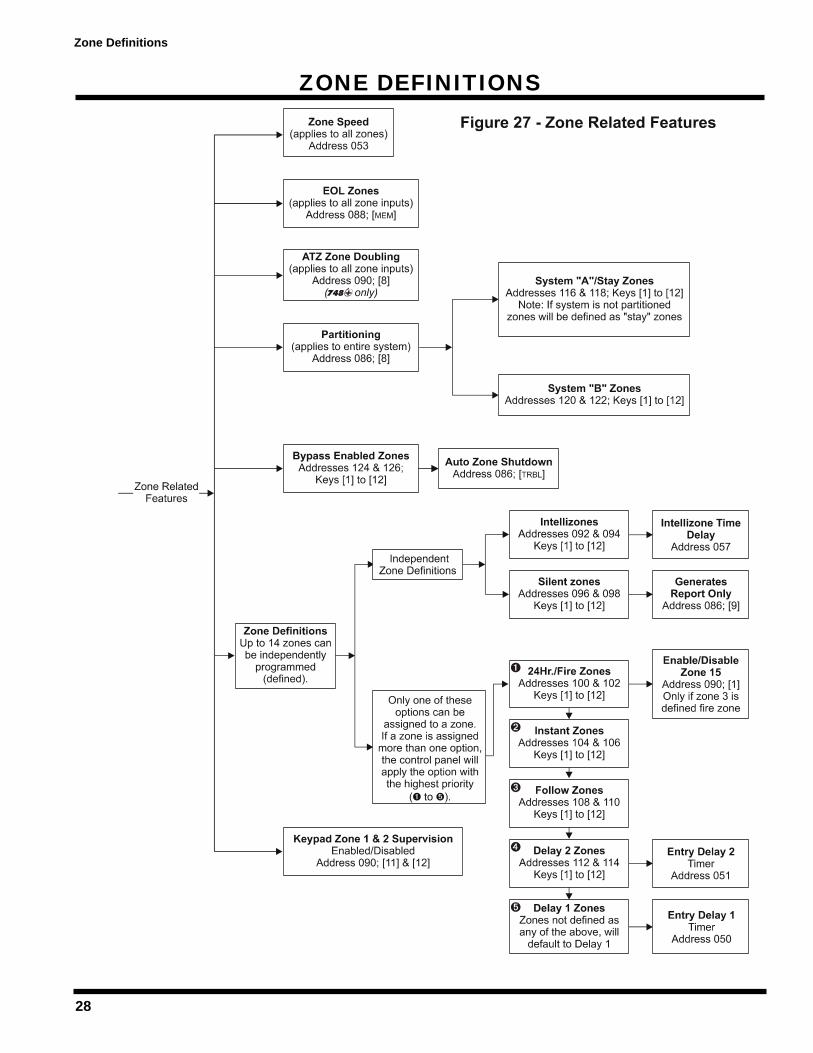
ZONE DEFINITIONS . . . . . . . . . . . . . . . . . . . . . . . . . . . . . . . . . . . . . . . . . . . . . . . . . . . . . . . . . . . . . . . . . . . . . . . . . . . . 287.1 Zone Speed . . . . . . . . . . . . . . . . . . . . . . . . . . . . . . . . . . . . . . . . . . . . . . . . . . . . . . . . . . . . . . . . . . . . . . . . . . . . . . . 29
Table of Contents
i
Table of Contents
ii
7.2 Advanced Technology Zoning (ATZ) . . . . . . . . . . . . . . . . . . . . . . . . . . . . . . . . . . . . . . . . . . . . . . . . . . . . . . . . . . . . 297.3 Intellizones . . . . . . . . . . . . . . . . . . . . . . . . . . . . . . . . . . . . . . . . . . . . . . . . . . . . . . . . . . . . . . . . . . . . . . . . . . . . . . . . 297.4 Silent Zones . . . . . . . . . . . . . . . . . . . . . . . . . . . . . . . . . . . . . . . . . . . . . . . . . . . . . . . . . . . . . . . . . . . . . . . . . . . . . . . 307.5 "24 Hour" & Fire Zones . . . . . . . . . . . . . . . . . . . . . . . . . . . . . . . . . . . . . . . . . . . . . . . . . . . . . . . . . . . . . . . . . . . . . . 307.6 Instant Zones . . . . . . . . . . . . . . . . . . . . . . . . . . . . . . . . . . . . . . . . . . . . . . . . . . . . . . . . . . . . . . . . . . . . . . . . . . . . . . 307.7 Follow Zones . . . . . . . . . . . . . . . . . . . . . . . . . . . . . . . . . . . . . . . . . . . . . . . . . . . . . . . . . . . . . . . . . . . . . . . . . . . . . . 307.8 Entry Delay 1 . . . . . . . . . . . . . . . . . . . . . . . . . . . . . . . . . . . . . . . . . . . . . . . . . . . . . . . . . . . . . . . . . . . . . . . . . . . . . . 317.9 Entry Delay 2 . . . . . . . . . . . . . . . . . . . . . . . . . . . . . . . . . . . . . . . . . . . . . . . . . . . . . . . . . . . . . . . . . . . . . . . . . . . . . . 317.10 Partitioning . . . . . . . . . . . . . . . . . . . . . . . . . . . . . . . . . . . . . . . . . . . . . . . . . . . . . . . . . . . . . . . . . . . . . . . . . . . . . . . . 317.11 Bypass Enabled Zones . . . . . . . . . . . . . . . . . . . . . . . . . . . . . . . . . . . . . . . . . . . . . . . . . . . . . . . . . . . . . . . . . . . . . . 327.12 EOL Zones (Enabled/Disabled) . . . . . . . . . . . . . . . . . . . . . . . . . . . . . . . . . . . . . . . . . . . . . . . . . . . . . . . . . . . . . . . . 327.13 Keypad Zone 1 Supervision . . . . . . . . . . . . . . . . . . . . . . . . . . . . . . . . . . . . . . . . . . . . . . . . . . . . . . . . . . . . . . . . . . . 337.14 Keypad Zone 2 Supervision . . . . . . . . . . . . . . . . . . . . . . . . . . . . . . . . . . . . . . . . . . . . . . . . . . . . . . . . . . . . . . . . . . . 33
ARM/DISARM & ALARM OPTIONS . . . . . . . . . . . . . . . . . . . . . . . . . . . . . . . . . . . . . . . . . . . . . . . . . . . . . . . . . . . . . . 348.1 "Timed" Auto Arming . . . . . . . . . . . . . . . . . . . . . . . . . . . . . . . . . . . . . . . . . . . . . . . . . . . . . . . . . . . . . . . . . . . . . . . . 358.2 "No Movement" Auto Arming . . . . . . . . . . . . . . . . . . . . . . . . . . . . . . . . . . . . . . . . . . . . . . . . . . . . . . . . . . . . . . . . . . 358.3 "One-Key" Regular Arming . . . . . . . . . . . . . . . . . . . . . . . . . . . . . . . . . . . . . . . . . . . . . . . . . . . . . . . . . . . . . . . . . . . 368.4 "One-Key" Stay/System A Arming . . . . . . . . . . . . . . . . . . . . . . . . . . . . . . . . . . . . . . . . . . . . . . . . . . . . . . . . . . . . . . 368.5 Arming using PS1 or keyswitch . . . . . . . . . . . . . . . . . . . . . . . . . . . . . . . . . . . . . . . . . . . . . . . . . . . . . . . . . . . . . . . . 368.6 Bell Squawk . . . . . . . . . . . . . . . . . . . . . . . . . . . . . . . . . . . . . . . . . . . . . . . . . . . . . . . . . . . . . . . . . . . . . . . . . . . . . . . 368.7 Exit Delay . . . . . . . . . . . . . . . . . . . . . . . . . . . . . . . . . . . . . . . . . . . . . . . . . . . . . . . . . . . . . . . . . . . . . . . . . . . . . . . . . 378.8 Beep on Exit delay . . . . . . . . . . . . . . . . . . . . . . . . . . . . . . . . . . . . . . . . . . . . . . . . . . . . . . . . . . . . . . . . . . . . . . . . . . 378.9 Alarm Transmission Delay . . . . . . . . . . . . . . . . . . . . . . . . . . . . . . . . . . . . . . . . . . . . . . . . . . . . . . . . . . . . . . . . . . . . 378.10 Silent Zones & Silent Panics Option . . . . . . . . . . . . . . . . . . . . . . . . . . . . . . . . . . . . . . . . . . . . . . . . . . . . . . . . . . . . 378.11 Bell Cut-Off Time . . . . . . . . . . . . . . . . . . . . . . . . . . . . . . . . . . . . . . . . . . . . . . . . . . . . . . . . . . . . . . . . . . . . . . . . . . . 378.12 Code Priority . . . . . . . . . . . . . . . . . . . . . . . . . . . . . . . . . . . . . . . . . . . . . . . . . . . . . . . . . . . . . . . . . . . . . . . . . . . . . . 38
PGM (PROGRAMMABLE OUTPUT) . . . . . . . . . . . . . . . . . . . . . . . . . . . . . . . . . . . . . . . . . . . . . . . . . . . . . . . . . . . . . 399.1 PGM Types . . . . . . . . . . . . . . . . . . . . . . . . . . . . . . . . . . . . . . . . . . . . . . . . . . . . . . . . . . . . . . . . . . . . . . . . . . . . . . . 399.2 PGM Timer Setting . . . . . . . . . . . . . . . . . . . . . . . . . . . . . . . . . . . . . . . . . . . . . . . . . . . . . . . . . . . . . . . . . . . . . . . . . . 409.3 PGM Options . . . . . . . . . . . . . . . . . . . . . . . . . . . . . . . . . . . . . . . . . . . . . . . . . . . . . . . . . . . . . . . . . . . . . . . . . . . . . . 40
OTHER OPTIONS . . . . . . . . . . . . . . . . . . . . . . . . . . . . . . . . . . . . . . . . . . . . . . . . . . . . . . . . . . . . . . . . . . . . . . . . . . . . . . . 4110.1 Telephone Line Monitoring (TLM) . . . . . . . . . . . . . . . . . . . . . . . . . . . . . . . . . . . . . . . . . . . . . . . . . . . . . . . . . . . . . . 4110.2 Dialing Options . . . . . . . . . . . . . . . . . . . . . . . . . . . . . . . . . . . . . . . . . . . . . . . . . . . . . . . . . . . . . . . . . . . . . . . . . . . . . 4110.3 Dialing Pulse Rates . . . . . . . . . . . . . . . . . . . . . . . . . . . . . . . . . . . . . . . . . . . . . . . . . . . . . . . . . . . . . . . . . . . . . . . . . 4110.4 Keypad Panic Options . . . . . . . . . . . . . . . . . . . . . . . . . . . . . . . . . . . . . . . . . . . . . . . . . . . . . . . . . . . . . . . . . . . . . . . 4110.5 Panel Time . . . . . . . . . . . . . . . . . . . . . . . . . . . . . . . . . . . . . . . . . . . . . . . . . . . . . . . . . . . . . . . . . . . . . . . . . . . . . . . . 4210.6 Time Correction . . . . . . . . . . . . . . . . . . . . . . . . . . . . . . . . . . . . . . . . . . . . . . . . . . . . . . . . . . . . . . . . . . . . . . . . . . . . 4210.7 Tamper/Wire Fault Recognition Options . . . . . . . . . . . . . . . . . . . . . . . . . . . . . . . . . . . . . . . . . . . . . . . . . . . . . . . . . 4310.8 Tamper Bypass Options . . . . . . . . . . . . . . . . . . . . . . . . . . . . . . . . . . . . . . . . . . . . . . . . . . . . . . . . . . . . . . . . . . . . . . 4310.9 Installer Test Mode . . . . . . . . . . . . . . . . . . . . . . . . . . . . . . . . . . . . . . . . . . . . . . . . . . . . . . . . . . . . . . . . . . . . . . . . . . 4310.10 Exclude Power Failure From Trouble Display . . . . . . . . . . . . . . . . . . . . . . . . . . . . . . . . . . . . . . . . . . . . . . . . . . . . . 4410.11 Audible Trouble Warning . . . . . . . . . . . . . . . . . . . . . . . . . . . . . . . . . . . . . . . . . . . . . . . . . . . . . . . . . . . . . . . . . . . . . 4410.12 Power Down Reset . . . . . . . . . . . . . . . . . . . . . . . . . . . . . . . . . . . . . . . . . . . . . . . . . . . . . . . . . . . . . . . . . . . . . . . . . 44
USER/KEYPAD FUNCTIONS . . . . . . . . . . . . . . . . . . . . . . . . . . . . . . . . . . . . . . . . . . . . . . . . . . . . . . . . . . . . . . . . . . . . 4511.1 Programming Master & User Codes . . . . . . . . . . . . . . . . . . . . . . . . . . . . . . . . . . . . . . . . . . . . . . . . . . . . . . . . . . . . 4511.2 Regular Arming . . . . . . . . . . . . . . . . . . . . . . . . . . . . . . . . . . . . . . . . . . . . . . . . . . . . . . . . . . . . . . . . . . . . . . . . . . . . 4511.3 Away Arming . . . . . . . . . . . . . . . . . . . . . . . . . . . . . . . . . . . . . . . . . . . . . . . . . . . . . . . . . . . . . . . . . . . . . . . . . . . . . . 4611.4 Stay Arming . . . . . . . . . . . . . . . . . . . . . . . . . . . . . . . . . . . . . . . . . . . . . . . . . . . . . . . . . . . . . . . . . . . . . . . . . . . . . . . 4611.5 Arming/Disarming Partitions . . . . . . . . . . . . . . . . . . . . . . . . . . . . . . . . . . . . . . . . . . . . . . . . . . . . . . . . . . . . . . . . . . . 4711.6 System Disarming . . . . . . . . . . . . . . . . . . . . . . . . . . . . . . . . . . . . . . . . . . . . . . . . . . . . . . . . . . . . . . . . . . . . . . . . . . 4811.7 Alarm Memory . . . . . . . . . . . . . . . . . . . . . . . . . . . . . . . . . . . . . . . . . . . . . . . . . . . . . . . . . . . . . . . . . . . . . . . . . . . . . 4811.8 Keyswitch or Pushbutton Arming/Disarming . . . . . . . . . . . . . . . . . . . . . . . . . . . . . . . . . . . . . . . . . . . . . . . . . . . . . . 4811.9 Manual Zone Bypassing . . . . . . . . . . . . . . . . . . . . . . . . . . . . . . . . . . . . . . . . . . . . . . . . . . . . . . . . . . . . . . . . . . . . . 4811.10 Bypass Recall . . . . . . . . . . . . . . . . . . . . . . . . . . . . . . . . . . . . . . . . . . . . . . . . . . . . . . . . . . . . . . . . . . . . . . . . . . . . . 4911.11 Keypad Chime Zones . . . . . . . . . . . . . . . . . . . . . . . . . . . . . . . . . . . . . . . . . . . . . . . . . . . . . . . . . . . . . . . . . . . . . . . . 4911.12 Trouble Display Monitoring . . . . . . . . . . . . . . . . . . . . . . . . . . . . . . . . . . . . . . . . . . . . . . . . . . . . . . . . . . . . . . . . . . . 4911.13 Key Access Programming . . . . . . . . . . . . . . . . . . . . . . . . . . . . . . . . . . . . . . . . . . . . . . . . . . . . . . . . . . . . . . . . . . . . 51
1
Introduction
INTRODUCTION
Thank you for placing your trust in Paradox and its improved Esprit 748 / 748 EXPRESS control panel. The enhanced control panel offers to you the same great features you have come todepend on with added reliability, improved lightning protection and a new innovative dialer circuit.You have selected a sophisticated, user-friendly control panel designed to meet all of yourtechnological, performance and security requirements.
1.1 About This ManualThis manual provides all the information you will need to understand panel operation, features andfunctions. If you are familiar with other security control panels, we recommend that you read thismanual at least once to familiarize yourself with panel features and programming. Please refer tothe index for a complete list of this manual's contents.
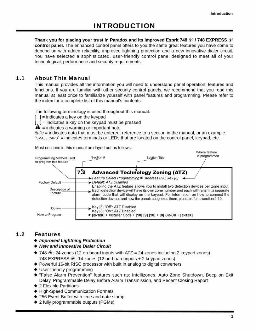
The following terminology is used throughout this manual:[ ] = indicates a key on the keypad[ ] = indicates a key on the keypad must be pressed
= indicates a warning or important noteitalic = indicates data that must be entered, reference to a section in the manual, or an example“SMALL CAPS” = indicates terminals or LEDs that are located on the control panel, keypad, etc.
1.2 FeaturesImproved Lightning ProtectionNew and Innovative Dialer Circuit748 : 24 zones (12 on-board inputs with ATZ = 24 zones including 2 keypad zones)748 EXPRESS : 14 zones (12 on-board inputs + 2 keypad zones)Powerful 16-bit RISC processor with built in analog to digital convertersUser-friendly programming"False Alarm Prevention" features such as: Intellizones, Auto Zone Shutdown, Beep on ExitDelay, Programmable Delay Before Alarm Transmission, and Recent Closing Report2 Flexible PartitionsHigh-Speed Communication Formats256 Event Buffer with time and date stamp2 fully programmable outputs (PGMs)

Introduction
2
Upload & Download capability with Espload SoftwareAlarm Relay (Optional on 748 EXPRESS )48 User Codes + 1 Master Code + 1 Installer CodeTelephone Line Supervision3 keypad activated panic alarmsRegular Arming, "Stay" Arming, "Double Stay" Arming, Force "Away" Arming, "One- Key” RegularArm, "One-Key" Stay Arm, "One-Key" Exit & Re-arm, "Auto Arming", Key Switch/PS1 Arming
1.3 SpecificationsBattery Charger: 360mA with dynamic Battery test.Aux. power: Two auxiliary outputs rated at 1A each. Fuseless electronic shutdown
at 1.1A, automatic restoreBell Out: 1A, Fuseless electronic shutdown at 3A, automatic restoreAC input: 16.5 VAC, 40VA min. (recommended: 75VA), 50 - 60HzPGM outputs: N.C. or N.O to ground, 50mA Max. Serial Data Output: (1200, 1, N) for use with accessory modules (not UL systems).
1.4 Accessories & KeypadsIf you would like to obtain more information on the following keypads, security system accessoriesor other security products, please contact your local Paradox distributor or come and visit us at ourweb site http://www.paradox.ca
Esprit 616/626 KeypadsEsprit 629 "Multi-Task" KeypadEsprit 633 LED KeypadEsprit 639 LCD KeypadsA wide range of analog and digital Motion DetectorsGlass Break DetectorPS1 Bedside Remote & Panic StationSRI18 Programmable Output (18) Expander Module708 Secondary Digital CommunicatorEsprint 300 Local Printer ModuleATZ 308 Zone Interface ModuleADP1 Telephone Line SimulatorSwivel Mount Bracket (469)
1.5 About ParadoxParadox Security Systems strives to design and manufacture the best security products moneycould buy. Our products are of the highest quality standards and most importantly meet the needsand expectations of our customers.
By refusing to settle for the limitations of existing technology, Paradox makes it clear, we are notinterested in mirroring the products already on the market. Breaking down barriers to bettertechnology is what innovation is all about.
The guiding principle behind Paradox research and development has always been to createsecurity products that make sense. Whether the situation calls for a full range of "intelligent" andeasy to use control panels, efficient peripheral security devices, or "false alarm free" motion orbreaking glass detectors. We are putting all our resources into developing products that reflect ourtwin philosophies of innovation and user-friendliness. Now we invite you to reap the benefits.
3
Installation
INSTALLATION2.1 Location & Mounting
Remove the printed circuit board, mounting hardware and keypad from the packaging inside thepanel box. The circuit board should not be mounted into the back of the cabinet, until all cables arepulled into the cabinet and prepared for connection. Before mounting the cabinet, push the fivewhite nylon-mounting studs into the back of the cabinet. Select an installation site that is not easilyaccessible to intruders. Leave at least 2" around the panel box to permit adequate ventilation andheat dissipation. The installation site should be dry and close to an AC source, ground connectionand telephone line connection.
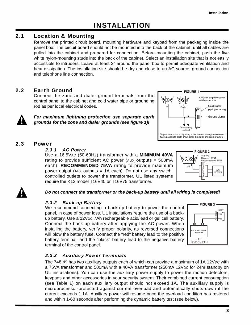
2.2 Earth GroundConnect the zone and dialer ground terminals from thecontrol panel to the cabinet and cold water pipe or groundingrod as per local electrical codes.
For maximum lightning protection use separate earthgrounds for the zone and dialer grounds (see figure 1)!
2.3 Power2.3.1 AC PowerUse a 16.5VAC (50-60Hz) transformer with a MINIMUM 40VArating to provide sufficient AC power (AUX outputs = 500mAeach); RECOMMENDED 75VA rating to provide maximumpower output (AUX outputs = 1A each). Do not use any switch-controlled outlets to power the transformer. UL listed systemsrequire the K12 model T16V40 or T16V75 transformer.
Do not connect the transformer or the back-up battery until all wiring is completed!
2.3.2 Back-up BatteryWe recommend connecting a back-up battery to power the controlpanel, in case of power loss. UL installations require the use of a back-up battery. Use a 12VDC 7Ah rechargeable acid/lead or gel cell battery.Connect the back-up battery after applying the AC power. Wheninstalling the battery, verify proper polarity, as reversed connectionswill blow the battery fuse. Connect the "red" battery lead to the positivebattery terminal, and the "black" battery lead to the negative batteryterminal of the control panel.
2.3.3 Auxiliary Power TerminalsThe 748 has two auxiliary outputs each of which can provide a maximum of 1A 12VDC witha 75VA transformer and 500mA with a 40VA transformer (250mA 12VDC for 24hr standby onUL installations). You can use the auxiliary power supply to power the motion detectors,keypads and other accessories in your security system. Their combined current consumption(see Table 1) on each auxiliary output should not exceed 1A. The auxiliary supply ismicroprocessor-protected against current overload and automatically shuts down if thecurrent exceeds 1.1A. Auxiliary power will resume once the overload condition has restoredand within 1-60 seconds after performing the dynamic battery test (see below).

4
Installation
2.3.4 Battery TestThe control panel conducts a dynamic battery test under load every 60 seconds. If the batteryis disconnected, or its capacity is too low, the [1] key in the trouble display mode will be on.Key [1] also comes "on" if the battery voltage drops to 10.5 volts or less when the controlpanel is running on the back-up battery (no AC). At 8.5 volts, the panel shuts down and alloutputs close.
2.3.5 Keypad Function TestWe recommend conducting a "power-up" test on keypads installed far from the control panel.To do so temporarily connect the keypads near the control panel and connect thetransformer. After 10 seconds, begin entering random commands on the keypad and verifythat the keypad "beeps" in response to these commands. Then open a zone to ensure thatthe keypad and the control panel are responding to these signals. If the keypad does notrespond and indicator lights do not illuminate, verify that approximately 16VAC is present atthe "AC" terminals. If AC is present, check the keypad wiring and verify there isn't a shortbetween the "black" and "red" keypad wires. If the keypad does not respond, please contactyour local Paradox Distributor.
2.4 Telephone Line ConnectionConnect the incoming telephone company wires into the TIPand RING connections of the control panel. Then run the wiresfrom T-1 and R-1 to the telephone system as shown in figure 4.
Table 1 - Current Consumption
Motion Detectors 10-50mA typ. 633 LED Keypad 15mA DC typ.(see detector instructions for details) 35mA DC max.
616/626 Keypads 15mA DC typ. PS1 Bedside Remote 15mA DC typ.30mA DC max. 20mA DC max.
629 "Multi-Task" Keypad 30mA DC typ. 708 Comm. Module 35mA DC typ.55mA DC max. 75mA DC max.
639/640 LCD Keypads 20mA DC typ. 708DV Comm. Module 70mA DC typ.70mA DC max. 105mA DC max.
SRI-18 46mA DC typ Esprint Printer Module 35mA typ.135mA DC max.
5
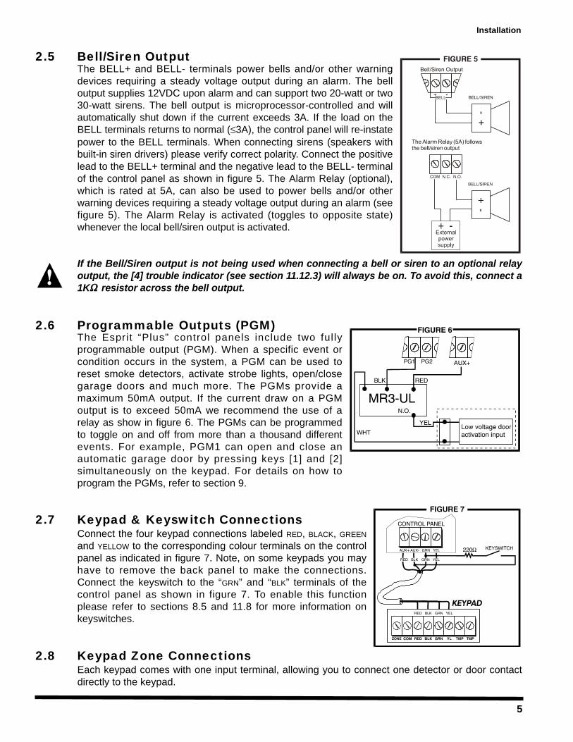
2.5 Bell/Siren OutputThe BELL+ and BELL- terminals power bells and/or other warningdevices requiring a steady voltage output during an alarm. The belloutput supplies 12VDC upon alarm and can support two 20-watt or two30-watt sirens. The bell output is microprocessor-controlled and willautomatically shut down if the current exceeds 3A. If the load on theBELL terminals returns to normal ( 3A), the control panel will re-instatepower to the BELL terminals. When connecting sirens (speakers withbuilt-in siren drivers) please verify correct polarity. Connect the positivelead to the BELL+ terminal and the negative lead to the BELL- terminalof the control panel as shown in figure 5. The Alarm Relay (optional),which is rated at 5A, can also be used to power bells and/or otherwarning devices requiring a steady voltage output during an alarm (seefigure 5). The Alarm Relay is activated (toggles to opposite state)whenever the local bell/siren output is activated.
If the Bell/Siren output is not being used when connecting a bell or siren to an optional relayoutput, the [4] trouble indicator (see section 11.12.3) will always be on. To avoid this, connect a1K resistor across the bell output.
2.6 Programmable Outputs (PGM)The Esprit “Plus” control panels include two fullyprogrammable output (PGM). When a specific event orcondition occurs in the system, a PGM can be used toreset smoke detectors, activate strobe lights, open/closegarage doors and much more. The PGMs provide amaximum 50mA output. If the current draw on a PGMoutput is to exceed 50mA we recommend the use of arelay as show in figure 6. The PGMs can be programmedto toggle on and off from more than a thousand differentevents. For example, PGM1 can open and close anautomatic garage door by pressing keys [1] and [2]simultaneously on the keypad. For details on how toprogram the PGMs, refer to section 9.
2.7 Keypad & Keyswitch ConnectionsConnect the four keypad connections labeled RED, BLACK, GREENand YELLOW to the corresponding colour terminals on the controlpanel as indicated in figure 7. Note, on some keypads you mayhave to remove the back panel to make the connections.Connect the keyswitch to the “GRN” and “BLK” terminals of thecontrol panel as shown in figure 7. To enable this functionplease refer to sections 8.5 and 11.8 for more information onkeyswitches.
2.8 Keypad Zone ConnectionsEach keypad comes with one input terminal, allowing you to connect one detector or door contactdirectly to the keypad.
Installation
6
Example: A door contact located at the entry point of an establishment can be wireddirectly to the input terminal of the entry point keypad instead of wiring the door contactall the way to the control panel.
If a keypad has the ATZ (zone doubling) feature, two detection devices can be connected to oneinput terminal. Each device will be assigned a zone (see table below) and each will transmit aseparate alarm code, therefore, capable of adding one or two zones to your security system.Regardless of the number of keypads in the system, the control panel supports a maximum of twokeypad zones.
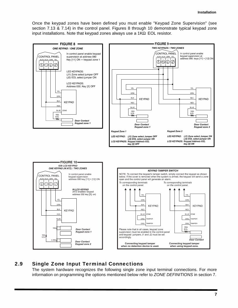
Example 1: A security installation is comprised of five keypads. Of these five keypadsonly two can have their zone input terminals enabled (see figure 9). The other threekeypads must have their zone input terminals disabled as described below.
Example 2: A security installation is comprised of three 616 keypads and two 639 LCDkeypads. You can enable the ATZ (Zone Doubling) feature on one of the 639 keypads,providing you with 2 zones on one keypad input terminal (see Figure 10). The remainingfour keypads must have their input terminals disabled as described below.
Note if using two keypad zones, one keypad must be defined as keypad zone 1 while the othermust be defined as keypad zone 2. Unless you are using an LCD keypad with the ATZ (zonedoubling) feature enabled, in which case the LCD will automatically define the keypad zones. Thecontrol panel will recognize these added zones as shown in the table below.
Disabling 616/626 Keypad Zones:If the keypad zone input terminal is not being used, disable it by shorting the blue zone wire withthe black COM wire of the keypad.
Disabling 629, 633, 639/640 Keypad Zones:If the keypad zone input terminal is not being used, disable it by shorting the ZONE and COMterminals of the keypad with a 1K resistor.
Keypad Zone Recognition
If using an LED keypad simply set the Zone Select Jumper at the back of the keypad:Zone Select Jumper "OFF" = Keypad Zone 1Zone Select Jumper "ON" = Keypad Zone 2Note: If the zone select jumper is changed, the control panel will only recognize the change
when the keypad is disconnected and re-connected.
If using an LCD keypad with ATZ disabled, program the keypad definition as follows:LCD Keypad Address 032; Key [2] "OFF" = Keypad Zone 1LCD Keypad Address 032; Key [2] "ON" = Keypad Zone 2
The control panel will display open keypad zones as follows:
748 and 748 EXPRESS Kpd Zone 1 = Zone [13]Kpd Zone 2 = Zone [14]
Note: When the ATZ feature is enabled in the control panel, it will not be able to distinguish between zone 13 and keypad zone 1 and between zone 14 and keypad zone 2 (see section 2.10)
Installation
7
Once the keypad zones have been defined you must enable "Keypad Zone Supervision" (seesection 7.13 & 7.14) in the control panel. Figures 8 through 10 demonstrate typical keypad zoneinput installations. Note that keypad zones always use a 1K EOL resistor.
2.9 Single Zone Input Terminal ConnectionsThe system hardware recognizes the following single zone input terminal connections. For moreinformation on programming the options mentioned below refer to ZONE DEFINITIONS in section 7.
Installation
8
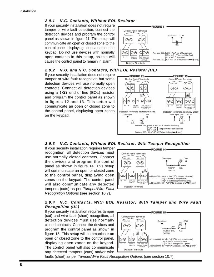
2.9.1 N.C. Contacts, Without EOL ResistorIf your security installation does not requiretamper or wire fault detection, connect thedetection devices and program the controlpanel as shown in figure 11. This setup willcommunicate an open or closed zone to thecontrol panel, displaying open zones on thekeypad. Do not use devices with normallyopen contacts in this setup, as this willcause the control panel to remain in alarm.
2.9.2 N.O. and N.C. Contacts, With EOL Resistor (UL)If your security installation does not requiretamper or wire fault recognition but somedetection devices will use normally opencontacts. Connect all detection devicesusing a 1K end of line (EOL) resistorand program the control panel as shownin figures 12 and 13. This setup willcommunicate an open or closed zone tothe control panel, displaying open zoneson the keypad.
2.9.3 N.C. Contacts, Without EOL Resistor, With Tamper RecognitionIf your security installation requires tamperrecognition, all detection devices mustuse normally closed contacts. Connectthe devices and program the controlpanel as shown in figure 14. This setupwill communicate an open or closed zoneto the control panel, displaying openzones on the keypad. The control panelwill also communicate any detectedtampers (cuts) as per Tamper/Wire FaultRecognition Options (see section 10.7).
2.9.4 N.C. Contacts, With EOL Resistor, With Tamper and Wire FaultRecognition (UL)If your security installation requires tamper(cut) and wire fault (short) recognition, alldetection devices must use normallyclosed contacts. Connect the devices andprogram the control panel as shown infigure 15. This setup will communicate anopen or closed zone to the control panel,displaying open zones on the keypad.The control panel will also communicateany detected tampers (cuts) and/or wirefaults (short) as per Tamper/Wire Fault Recognition Options (see section 10.7).
Installation
9
2.10 Advanced Technology Zone (ATZ) Connections
This feature is not available on the 748 EXPRESS control panel.
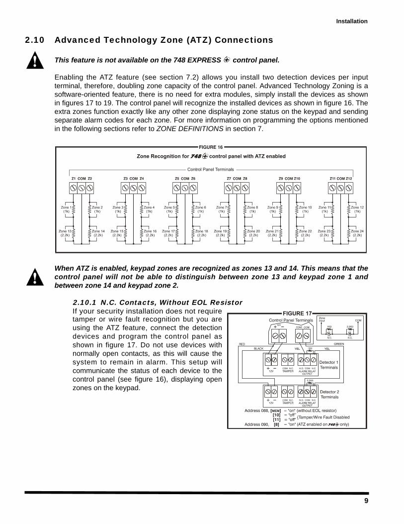
Enabling the ATZ feature (see section 7.2) allows you install two detection devices per inputterminal, therefore, doubling zone capacity of the control panel. Advanced Technology Zoning is asoftware-oriented feature, there is no need for extra modules, simply install the devices as shownin figures 17 to 19. The control panel will recognize the installed devices as shown in figure 16. Theextra zones function exactly like any other zone displaying zone status on the keypad and sendingseparate alarm codes for each zone. For more information on programming the options mentionedin the following sections refer to ZONE DEFINITIONS in section 7.
When ATZ is enabled, keypad zones are recognized as zones 13 and 14. This means that thecontrol panel will not be able to distinguish between zone 13 and keypad zone 1 andbetween zone 14 and keypad zone 2.
2.10.1 N.C. Contacts, Without EOL ResistorIf your security installation does not requiretamper or wire fault recognition but you areusing the ATZ feature, connect the detectiondevices and program the control panel asshown in figure 17. Do not use devices withnormally open contacts, as this will cause thesystem to remain in alarm. This setup willcommunicate the status of each device to thecontrol panel (see figure 16), displaying openzones on the keypad.
Installation
10
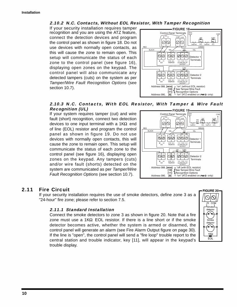
2.10.2 N.C. Contacts, Without EOL Resistor, With Tamper RecognitionIf your security installation requires tamperrecognition and you are using the ATZ feature,connect the detection devices and programthe control panel as shown in figure 18. Do notuse devices with normally open contacts, asthis will cause the zone to remain open. Thissetup will communicate the status of eachzone to the control panel (see figure 16),displaying open zones on the keypad. Thecontrol panel will also communicate anydetected tampers (cuts) on the system as perTamper/Wire Fault Recognition Options (seesection 10.7).
2.10.3 N.C. Contacts, With EOL Resistor, With Tamper & Wire FaultRecognition (UL)If your system requires tamper (cut) and wirefault (short) recognition, connect two detectiondevices to one input terminal with a 1K endof line (EOL) resistor and program the controlpanel as shown in figure 19. Do not usedevices with normally open contacts, this willcause the zone to remain open. This setup willcommunicate the status of each zone to thecontrol panel (see figure 16), displaying openzones on the keypad. Any tampers (cuts)and/or wire fault (shorts) detected on thesystem are communicated as per Tamper/WireFault Recognition Options (see section 10.7).
2.11 Fire CircuitIf your security installation requires the use of smoke detectors, define zone 3 as a"24-hour" fire zone; please refer to section 7.5.
2.11.1 Standard InstallationConnect the smoke detectors to zone 3 as shown in figure 20. Note that a firezone must use a 1K EOL resistor. If there is a line short or if the smokedetector becomes active, whether the system is armed or disarmed, thecontrol panel will generate an alarm (see Fire Alarm Output figure on page 30).If the line is "open", the control panel will send a "fire loop" trouble report to thecentral station and trouble indicator, key [11], will appear in the keypad’strouble display.
Installation
11
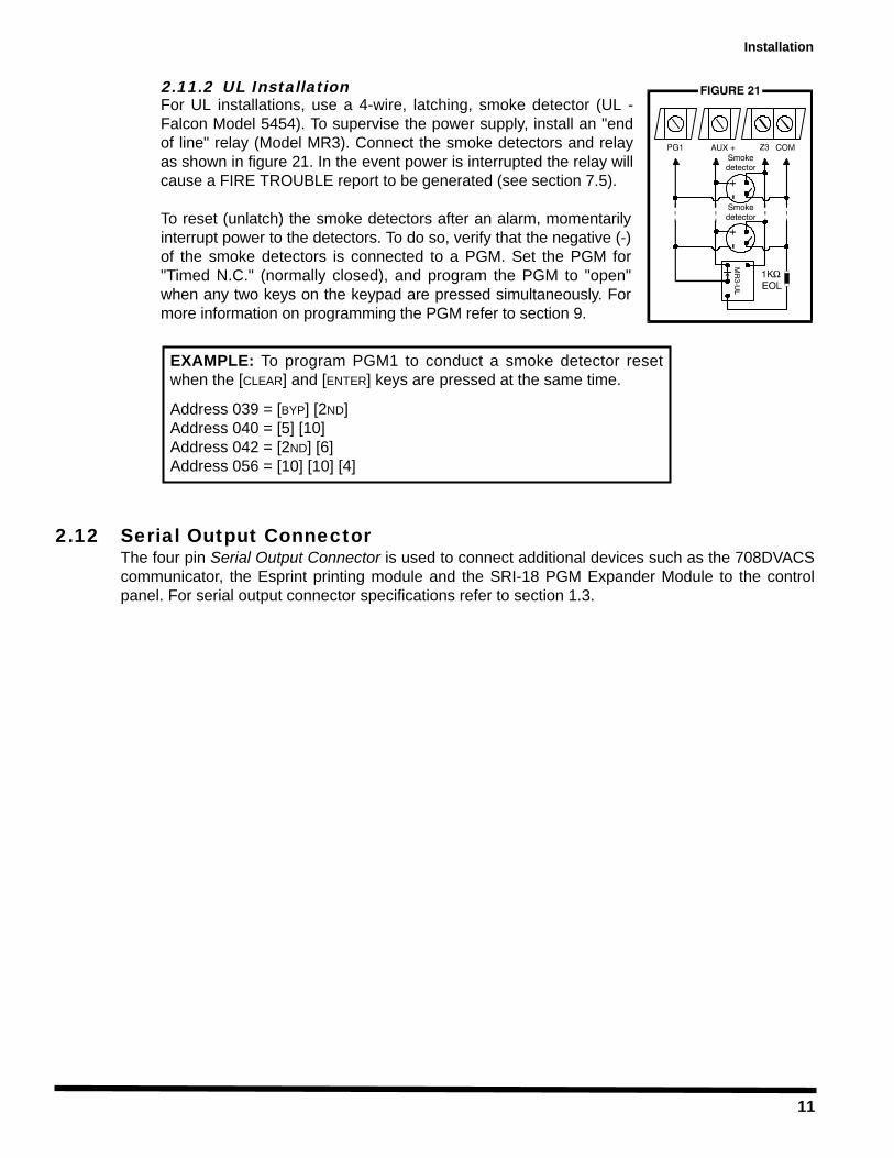
2.11.2 UL InstallationFor UL installations, use a 4-wire, latching, smoke detector (UL -Falcon Model 5454). To supervise the power supply, install an "endof line" relay (Model MR3). Connect the smoke detectors and relayas shown in figure 21. In the event power is interrupted the relay willcause a FIRE TROUBLE report to be generated (see section 7.5).
To reset (unlatch) the smoke detectors after an alarm, momentarilyinterrupt power to the detectors. To do so, verify that the negative (-)of the smoke detectors is connected to a PGM. Set the PGM for"Timed N.C." (normally closed), and program the PGM to "open"when any two keys on the keypad are pressed simultaneously. Formore information on programming the PGM refer to section 9.
2.12 Serial Output ConnectorThe four pin Serial Output Connector is used to connect additional devices such as the 708DVACScommunicator, the Esprint printing module and the SRI-18 PGM Expander Module to the controlpanel. For serial output connector specifications refer to section 1.3.
EXAMPLE: To program PGM1 to conduct a smoke detector resetwhen the [CLEAR] and [ENTER] keys are pressed at the same time.
Address 039 = [BYP] [2ND]Address 040 = [5] [10]Address 042 = [2ND] [6]Address 056 = [10] [10] [4]
Installation
12
ACCESS CODES
3.1 Installer CodeStreamline - Section 00 Hexa Programming - Addresses 000-002Default: 748 = 484848 / 748 EXPRESS = 747474Only the installer code allows you to program all control panel settings, except the Master and Usercodes. To program any setting in the control panel you must enter the programming mode bypressing the [ENTER] key followed by the installer code. The installer code contains six digits andeach digit can be any value from 0 to 9. Although the control panel can accept 4-digit codes, whenprogramming the installer code, always enter six digits. To change the installer code press:
[ENTER] + Installer Code + [10] [10] [10] + First 2 digits + [10] [10] [1] + Next 2 digits + [10] [10] [2]+ Final 2 digits + [ENTER]
3.2 Master & User CodesDefault Master Code: 474747You can not use the installer code to program the master and user codes. Only the master anduser 1 codes can program these access codes. (See section 11.1)
3.3 User / Access Code LengthFeature Select Programming Address 088, key [9]Default: 6-digit Access CodesWhen programming user codes an option for either 4-digit or 6-digit access codes can beprogrammed. When the 4-digit option is selected, entering a 4-digit code will allow the personaccess. Using the 6-digit option, entering 6 digits is required to allow access.
Key [9] "Off": 6-digit Access CodesKey [9] "On": 4-digit Access Codes [ENTER] + Installer Code + [10] [8] [8] + [9] On/Off + [ENTER] twice
3.4 DuressFeature Select Programming Address 090, key [10]Default: Duress DisabledWhen unwillingly forced to disarm a system, a User can enter the User Code #48 instead of theirusual code. This code will disarm the system and send a silent alert (Duress Code) to the Central.
Key [10] "Off": Duress DisabledKey [10] "On": Duress Enabled [ENTER] + Installer Code + [10] [9] [10] + [10] On/Off + [ENTER] twice
3.5 Installer LockDecimal Programming Address 058Default: Address EmptyProgram 147 into address 058 to lock all programming. Hence, performing a hardware reset (see section10.12) will not affect the current settings. To remove the installer lock, enter any value besides 147.
[ENTER] + Installer Code + [10] [5] [8] + [1] [4] [7] + [ENTER]
Access Codes
13
PROGRAMMING METHODS
The 748 & 748 EXPRESS Control Panels can be programmed using either the keypad or theEspload Software. We highly recommend programming the control panels using the EsploadSoftware, as it simplifies the process and reduces the potential of data entry errors. You can alsoprogram the control panels manually by using a keypad.
4.1 Espload SoftwareWith the Espload Software, you can program the 748 family of control panels remotely viamodem or locally using an ADP-1 adapter. The advanced Espload software can execute fastuploads or downloads and provides many powerful features. These include a comprehensive"monitoring" mode to oversee all panel activity, a "scheduler" to initiate pre-programmed tasks atset intervals, and a "batch" mode to carry out pre-programmed tasks following a call from thecontrol panel. Using Espload there is no limit to the number of account files or panel defaultscreated and you can assign thousands of programming combinations to the PGM outputs. Esploadcan also be converted to the language of your choice. Contact your local Paradox Distributor foryour FREE copy of the Espload software.
4.2 KeypadWhen programming, use the supplied "Programming Guide" to keep track of which addresses wereprogrammed and how. Before you begin programming the control panel, we recommend you readsections 5 through 11 of this manual in order to acquire a good understanding of the control paneland its many features. When programming with the keypad, certain addresses are programmedusing different methods. These methods are described in detail below. Each section in this manualwill reference the appropriate programming method.
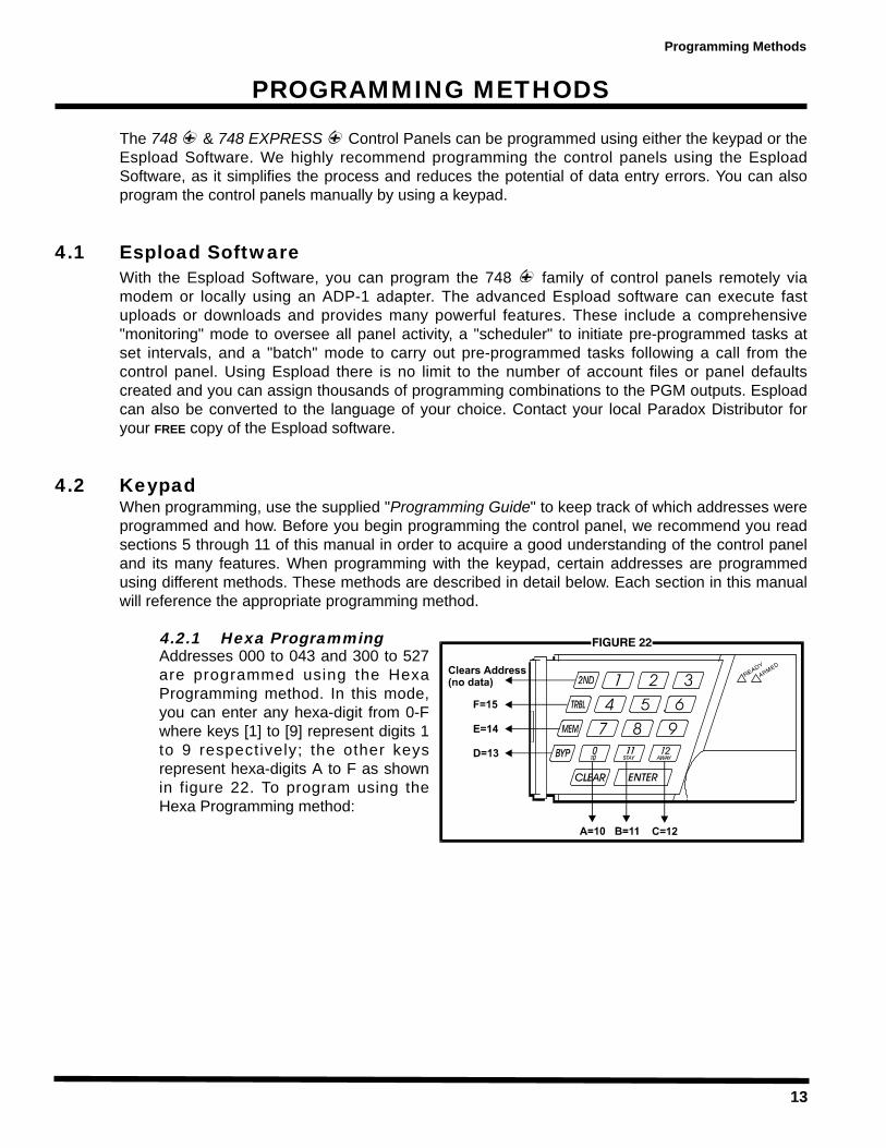
4.2.1 Hexa ProgrammingAddresses 000 to 043 and 300 to 527are programmed using the HexaProgramming method. In this mode,you can enter any hexa-digit from 0-Fwhere keys [1] to [9] represent digits 1to 9 respectively; the other keysrepresent hexa-digits A to F as shownin figure 22. To program using theHexa Programming method:
Programming Methods
14
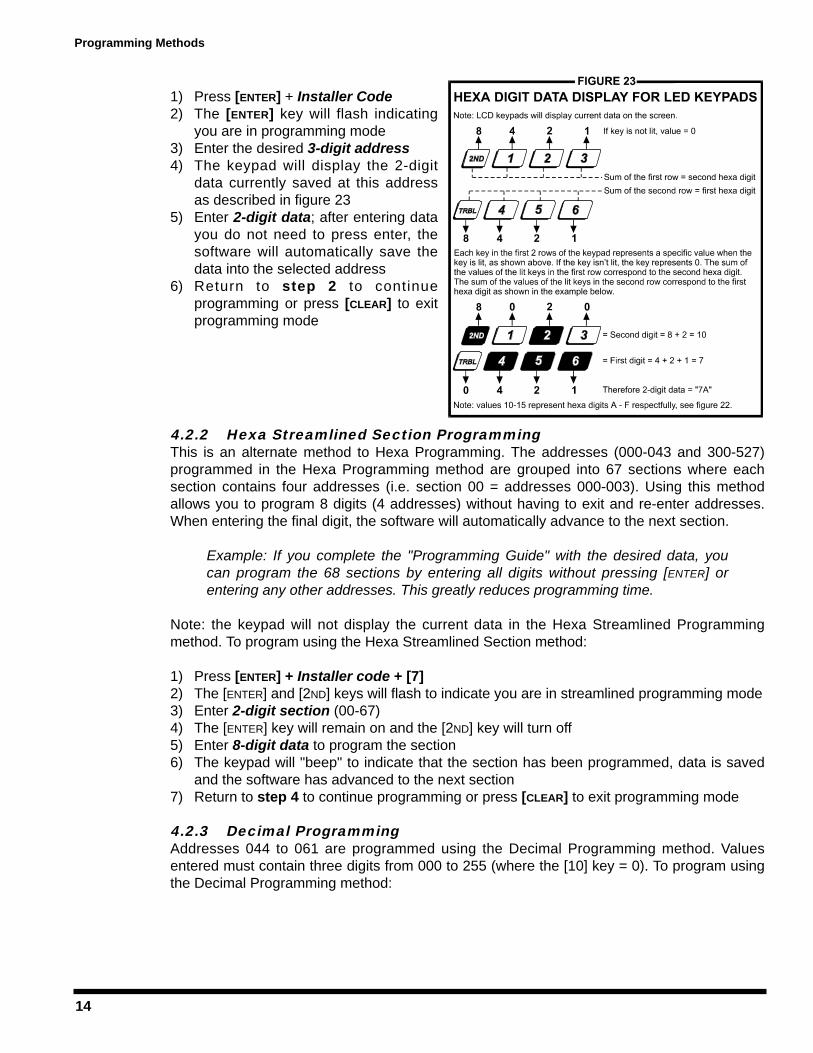
1) Press [ENTER] + Installer Code2) The [ENTER] key will flash indicating
you are in programming mode3) Enter the desired 3-digit address4) The keypad will display the 2-digit
data currently saved at this addressas described in figure 23
5) Enter 2-digit data; after entering datayou do not need to press enter, thesoftware will automatically save thedata into the selected address
6) Return to step 2 to continueprogramming or press [CLEAR] to exitprogramming mode
4.2.2 Hexa Streamlined Section ProgrammingThis is an alternate method to Hexa Programming. The addresses (000-043 and 300-527)programmed in the Hexa Programming method are grouped into 67 sections where eachsection contains four addresses (i.e. section 00 = addresses 000-003). Using this methodallows you to program 8 digits (4 addresses) without having to exit and re-enter addresses.When entering the final digit, the software will automatically advance to the next section.
Example: If you complete the "Programming Guide" with the desired data, youcan program the 68 sections by entering all digits without pressing [ENTER] orentering any other addresses. This greatly reduces programming time.
Note: the keypad will not display the current data in the Hexa Streamlined Programmingmethod. To program using the Hexa Streamlined Section method:
1) Press [ENTER] + Installer code + [7]2) The [ENTER] and [2ND] keys will flash to indicate you are in streamlined programming mode3) Enter 2-digit section (00-67)4) The [ENTER] key will remain on and the [2ND] key will turn off5) Enter 8-digit data to program the section6) The keypad will "beep" to indicate that the section has been programmed, data is saved
and the software has advanced to the next section7) Return to step 4 to continue programming or press [CLEAR] to exit programming mode
4.2.3 Decimal ProgrammingAddresses 044 to 061 are programmed using the Decimal Programming method. Valuesentered must contain three digits from 000 to 255 (where the [10] key = 0). To program usingthe Decimal Programming method:
Programming Methods
15
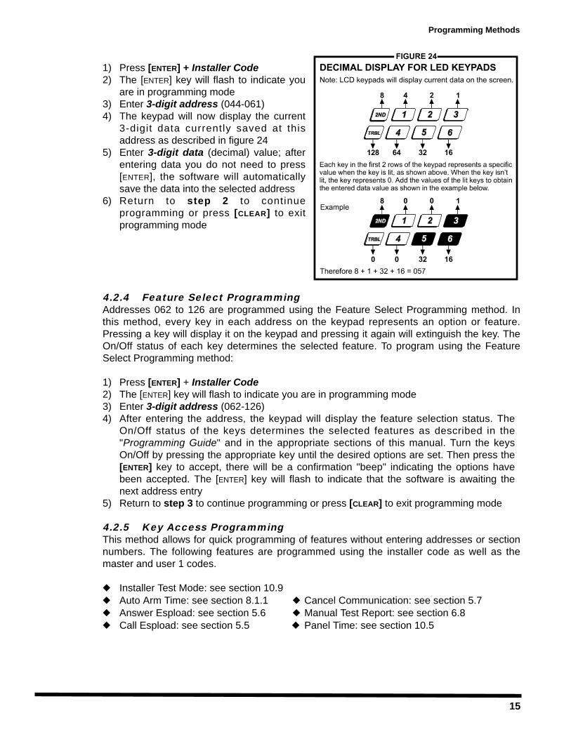
1) Press [ENTER] + Installer Code2) The [ENTER] key will flash to indicate you
are in programming mode3) Enter 3-digit address (044-061)4) The keypad will now display the current
3-digit data currently saved at thisaddress as described in figure 24
5) Enter 3-digit data (decimal) value; afterentering data you do not need to press[ENTER], the software will automaticallysave the data into the selected address
6) Return to step 2 to continueprogramming or press [CLEAR] to exitprogramming mode
4.2.4 Feature Select ProgrammingAddresses 062 to 126 are programmed using the Feature Select Programming method. Inthis method, every key in each address on the keypad represents an option or feature.Pressing a key will display it on the keypad and pressing it again will extinguish the key. TheOn/Off status of each key determines the selected feature. To program using the FeatureSelect Programming method:
1) Press [ENTER] + Installer Code2) The [ENTER] key will flash to indicate you are in programming mode3) Enter 3-digit address (062-126)4) After entering the address, the keypad will display the feature selection status. The
On/Off status of the keys determines the selected features as described in the"Programming Guide" and in the appropriate sections of this manual. Turn the keysOn/Off by pressing the appropriate key until the desired options are set. Then press the[ENTER] key to accept, there will be a confirmation "beep" indicating the options havebeen accepted. The [ENTER] key will flash to indicate that the software is awaiting thenext address entry
5) Return to step 3 to continue programming or press [CLEAR] to exit programming mode
4.2.5 Key Access ProgrammingThis method allows for quick programming of features without entering addresses or sectionnumbers. The following features are programmed using the installer code as well as themaster and user 1 codes.
Installer Test Mode: see section 10.9Auto Arm Time: see section 8.1.1 Cancel Communication: see section 5.7Answer Espload: see section 5.6 Manual Test Report: see section 6.8Call Espload: see section 5.5 Panel Time: see section 10.5
Programming Methods
16
PANEL SETTINGS FOR ESPLOAD
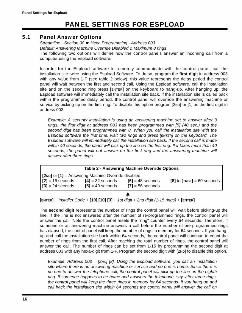
5.1 Panel Answer OptionsStreamline - Section 00 Hexa Programming - Address 003Default: Answering Machine Override Disabled & Maximum 8 ringsThe following two options will define how the control panels answer an incoming call from acomputer using the Espload software.
In order for the Espload software to remotely communicate with the control panel, call theinstallation site twice using the Espload Software. To do so, program the first digit in address 003with any value from 1-F (see table 2 below), this value represents the delay period the controlpanel will wait between the first and second call. Using the Espload software, call the installationsite and on the second ring press [ENTER] on the keyboard to hang-up. After hanging up, theEspload software will immediately call the installation site back. If the installation site is called backwithin the programmed delay period, the control panel will override the answering machine orservice by picking-up on the first ring. To disable this option program [2ND] or [1] as the first digit inaddress 003.
Example: A security installation is using an answering machine set to answer after 3rings, the first digit at address 003 has been programmed with [5] (40 sec.) and thesecond digit has been programmed with 8. When you call the installation site with theEspload software the first time, wait two rings and press [ENTER] on the keyboard. TheEspload software will immediately call the installation site back. If the second call is madewithin 40 seconds, the panel will pick up the line on the first ring. If it takes more than 40seconds, the panel will not answer on the first ring and the answering machine willanswer after three rings.
[ENTER] + Installer Code + [10] [10] [3] + 1st digit + 2nd digit (1-15 rings) + [ENTER]
The second digit represents the number of rings the control panel will wait before picking-up theline. If the line is not answered after the number of re-programmed rings, the control panel willanswer the call. Note the control panel resets the "ring" counter every 64 seconds. Therefore, ifsomeone or an answering machine answers a call before the number of pre-programmed ringshas elapsed, the control panel will keep the number of rings in memory for 64 seconds. If you hang-up and call the installation site back within 64 seconds, the control panel will continue to count thenumber of rings from the first call. After reaching the total number of rings, the control panel willanswer the call. The number of rings can be set from 1-15 by programming the second digit ataddress 003 with any hexa-digit from 1-F. Program the second digit with [2ND] to disable this option.
Example: Address 003 = [2ND] [8]. Using the Espload software, you call an installationsite where there is no answering machine or service and no one is home. Since there isno one to answer the telephone call, the control panel will pick-up the line on the eighthring. If someone happens to be home and answers the telephone, say, after three rings,the control panel will keep the three rings in memory for 64 seconds. If you hang-up andcall back the installation site within 64 seconds the control panel will answer the call on
Table 2 - Answering Machine Override Options[2ND] or [1] = Answering Machine Override disabled[2] = 16 seconds [4] = 32 seconds [6] = 48 seconds [8] to [TRBL] = 60 seconds[3] = 24 seconds [5] = 40 seconds [7] = 56 seconds
Panel Settings for Espload
17
the fifth ring. If you call back after 64 seconds the "ring" counter will have been reset andthe control panel will answer the call on the eighth ring.
If you program four or less rings, the control panel will always reset the counter!
5.2 Panel IdentifierStreamline - Section 01 Hexa Programming - Addresses 004-005This four-digit code identifies the control panel to the Espload software before initiating upload.Program the same 4-digit code into the control panel and the Espload software before attempting toestablish communication. If the codes do not match, the control panel will not establishcommunication. Enter any hexa digits from 0 to F.
[ENTER] + Installer Code + [10] [10] [4] + First 2 digits + [10] [10] [5] + Final 2 digits + [ENTER]
5.3 PC PasswordStreamline - Section 01 Hexa Programming - Addresses 006-007This four-digit download password identifies the PC to the panel, before beginning the downloadprocess. Enter the same password into the Espload software and the control panel. If the passwordsare not the same, Espload will not establish communication. Enter any hexa digits from 0 to F.
[ENTER] + Installer Code + [10] [10] [6] + First 2 digits + [10] [10] [7] + Final 2 digits + [ENTER]
5.4 Computer Telephone NumberStreamline Section 02 & 03 Hexa Programming - Address 008-015The control panel will dial this telephone number when trying to initiate communication with the PC(see section 5.5 Call Espload). There is no default telephone number and you can enter anynumber from 0-9 up to a maximum of 16 digits. If you would like to enter any special keys orfunctions refer to table 3 in section 6.3. If the telephone number contains less than 16 digits, pressthe [TRBL] key to indicate the end of the telephone number.
[ENTER] + Installer Code + [7] + [10] [2] + Telephone Number (if <16 digits press [TRBL]) + [ENTER]
5.5 Call EsploadKey Access Programming key [TRBL]The control panel will dial the telephone number entered at addresses 008-015 (see section 5.4) inorder to communicate with the Espload software. The control panel and the computer will verify thatthe Panel Identifier and the PC Password match before establishing communication (see sections5.2 and 5.3).
Press [ENTER] + (Installer, Master, or User 1 Code) + [TRBL]
5.6 Answer EsploadKey Access Programming Key [AWAY]By entering the code sequence listed below, you can manually force the control panel to answerany incoming calls from the Espload software. This option can also be used to perform an on-siteupload/download by connecting your computer directly to the control panel using an ADP-1 lineadapter and manually answering Espload from the control panel. In Espload go to:
Panel Settings for Espload
18
Main Menu Program Setup Modem & Printer ConfigurationSet "Dialing Condition" to "Blind Dial". Program the panel telephone number in Espload and followthe instructions on the ADP-1 adapter. When the computer has dialed press:
[ENTER] + (Installer, Master, or User 1 Code) + [AWAY]
5.7 Cancel CommunicationKey Access Programming key [STAY]Use the Installer Code to cancel all communication and erase any unreported events in the bufferuntil the next reportable event. Use the Master or User 1 code to cancel communication attemptswith Espload.
[ENTER] + (Installer, Master & User 1 Code) + [STAY]
5.8 Call BackFeature Select Programming Address 086, key [4]Default: Call Back DisabledFor additional security, when a PC using the Espload software attempts to communicate with thecontrol panel, the control panel can hang-up and call the PC back in order to re-verify identificationcodes and re-establish communication. When the control panel answers the call, it will verify if thePanel ID and PC Passwords match and if they do, the control panel will hang-up and call theEspload software back. The Espload software will automatically go into "wait for dial tone", ready toanswer when the control panel calls back. Please note the Computer Telephone Number (seesection 5.4) must be programmed in order to use the "Call Back" feature.
Key [4] "Off": Call Back DisabledKey [4] "On": Call Back Enabled [ENTER] + Installer Code + [10] [8] [6] + [4] On/Off + [ENTER] twice
5.9 Automatic Event Buffer TransmissionFeature Select Programming Address 088, key [2ND]Default: Automatic Event Buffer Transmission DisabledWhen the event buffer reaches 50% capacity, the control panel will make two attempts to establishcommunication with a PC. The control panel will call the Computer Telephone Number (see section5.4) programmed at addresses 008 to 015. The Espload software must be in "wait for dial tone"mode. When the system establishes communication, it will upload the contents of the event bufferto the Espload software. If communication is interrupted before transmission of the completecontents of the buffer, or if after two attempts, communication is not established, the system willwait until the event buffer is full before attempting to re-communicate with Espload. When the EventBuffer is full, each subsequent new event will erase the oldest event in the buffer.
Key [2ND] "Off": Automatic Event Buffer Transmission DisabledKey [2ND] "On": Automatic Event Buffer Transmission Enabled [ENTER] + Installer Code + [10] [8] [8] + [2ND] On/Off + [ENTER] twice
Panel Settings for Espload
19
EVENT REPORTING
Event Reporting
20
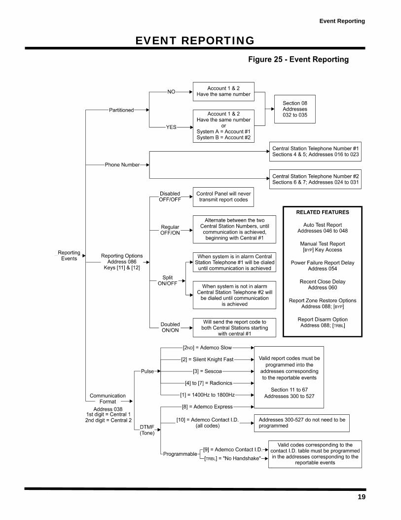
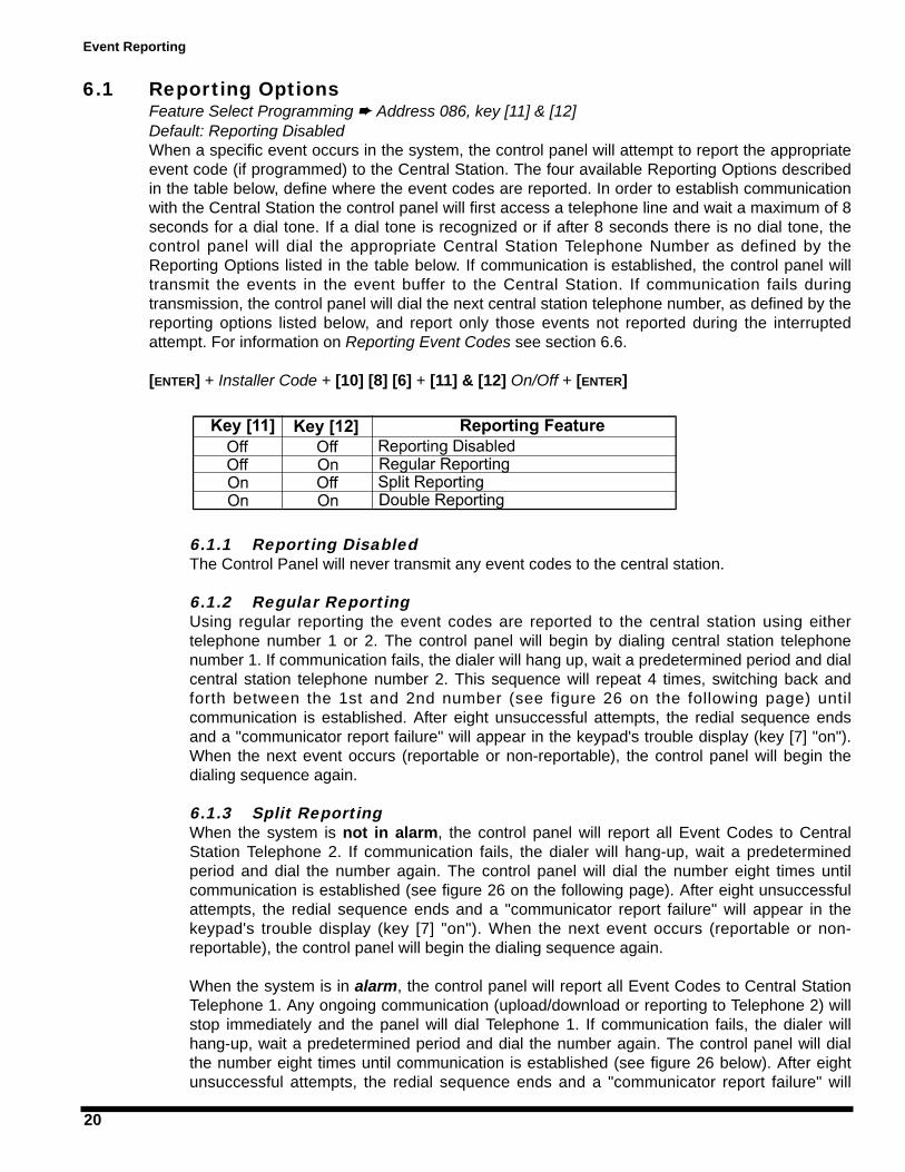
6.1 Reporting OptionsFeature Select Programming Address 086, key [11] & [12]Default: Reporting DisabledWhen a specific event occurs in the system, the control panel will attempt to report the appropriateevent code (if programmed) to the Central Station. The four available Reporting Options describedin the table below, define where the event codes are reported. In order to establish communicationwith the Central Station the control panel will first access a telephone line and wait a maximum of 8seconds for a dial tone. If a dial tone is recognized or if after 8 seconds there is no dial tone, thecontrol panel will dial the appropriate Central Station Telephone Number as defined by theReporting Options listed in the table below. If communication is established, the control panel willtransmit the events in the event buffer to the Central Station. If communication fails duringtransmission, the control panel will dial the next central station telephone number, as defined by thereporting options listed below, and report only those events not reported during the interruptedattempt. For information on Reporting Event Codes see section 6.6.
[ENTER] + Installer Code + [10] [8] [6] + [11] & [12] On/Off + [ENTER]
6.1.1 Reporting DisabledThe Control Panel will never transmit any event codes to the central station.
6.1.2 Regular ReportingUsing regular reporting the event codes are reported to the central station using eithertelephone number 1 or 2. The control panel will begin by dialing central station telephonenumber 1. If communication fails, the dialer will hang up, wait a predetermined period and dialcentral station telephone number 2. This sequence will repeat 4 times, switching back andforth between the 1st and 2nd number (see figure 26 on the following page) untilcommunication is established. After eight unsuccessful attempts, the redial sequence endsand a "communicator report failure" will appear in the keypad's trouble display (key [7] "on").When the next event occurs (reportable or non-reportable), the control panel will begin thedialing sequence again.
6.1.3 Split ReportingWhen the system is not in alarm, the control panel will report all Event Codes to CentralStation Telephone 2. If communication fails, the dialer will hang-up, wait a predeterminedperiod and dial the number again. The control panel will dial the number eight times untilcommunication is established (see figure 26 on the following page). After eight unsuccessfulattempts, the redial sequence ends and a "communicator report failure" will appear in thekeypad's trouble display (key [7] "on"). When the next event occurs (reportable or non-reportable), the control panel will begin the dialing sequence again.
When the system is in alarm, the control panel will report all Event Codes to Central StationTelephone 1. Any ongoing communication (upload/download or reporting to Telephone 2) willstop immediately and the panel will dial Telephone 1. If communication fails, the dialer willhang-up, wait a predetermined period and dial the number again. The control panel will dialthe number eight times until communication is established (see figure 26 below). After eightunsuccessful attempts, the redial sequence ends and a "communicator report failure" will
Event Reporting

21
appear in the keypad's trouble display (key [7] "on"). When the next event occurs (reportableor non-reportable), the control panel will begin the dialing sequence again.
6.1.4 Double ReportingIn double reporting, the control panel will report each event code to both central stationtelephone numbers. The control panel will begin by attempting communication with centralstation telephone 1 and if communication fails, the dialer will hang-up, wait a predeterminedperiod and dial the number again. The control panel will dial the number eight times untilcommunication is established (see figure 26). After eight unsuccessful attempts, the redialsequence ends and a "communicator report failure" will appear in the keypad's troubledisplay (key [7] "on"). If communication has been established and the event codestransmitted or if after eight attempts communication has not been established, the controlpanel will report the same Event Codes to Central Station Telephone 2.
6.2 Central Station Telephone Number 1Streamline - Section 04 & 05 Hexa Programming - Addresses 016-023The control panel will dial the programmed telephone number when reporting an event code to thecentral station computer (see Reporting Options in section 6.1). For example, if the alarm system isarmed and a zone with a motion detector opens, the control panel may dial the telephone numberin order to send the programmed event code to the central station computer. There is no defaulttelephone number and you can enter any number from 0-9 up to a maximum of 16 digits. If youwould like to enter any special keys or functions, refer to table 3 below. If the telephone numbercontains less than 16 digits, press the [TRBL] key to indicate the end of the telephone number.
[ENTER] + Installer Code + [7] + [10] [4] + Telephone Number + [ENTER] OR [TRBL] if number is <16 digits
Event Reporting
22
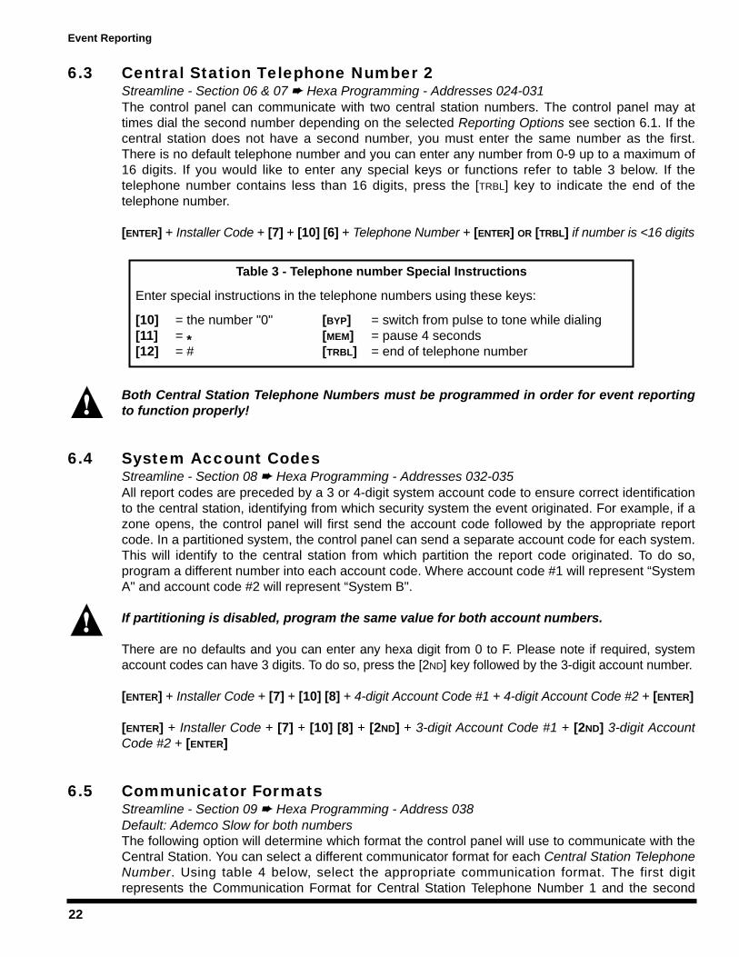
6.3 Central Station Telephone Number 2Streamline - Section 06 & 07 Hexa Programming - Addresses 024-031The control panel can communicate with two central station numbers. The control panel may attimes dial the second number depending on the selected Reporting Options see section 6.1. If thecentral station does not have a second number, you must enter the same number as the first.There is no default telephone number and you can enter any number from 0-9 up to a maximum of16 digits. If you would like to enter any special keys or functions refer to table 3 below. If thetelephone number contains less than 16 digits, press the [TRBL] key to indicate the end of thetelephone number.
[ENTER] + Installer Code + [7] + [10] [6] + Telephone Number + [ENTER] OR [TRBL] if number is <16 digits
Both Central Station Telephone Numbers must be programmed in order for event reportingto function properly!
6.4 System Account CodesStreamline - Section 08 Hexa Programming - Addresses 032-035All report codes are preceded by a 3 or 4-digit system account code to ensure correct identificationto the central station, identifying from which security system the event originated. For example, if azone opens, the control panel will first send the account code followed by the appropriate reportcode. In a partitioned system, the control panel can send a separate account code for each system.This will identify to the central station from which partition the report code originated. To do so,program a different number into each account code. Where account code #1 will represent “SystemA" and account code #2 will represent “System B".
If partitioning is disabled, program the same value for both account numbers.
There are no defaults and you can enter any hexa digit from 0 to F. Please note if required, systemaccount codes can have 3 digits. To do so, press the [2ND] key followed by the 3-digit account number.
[ENTER] + Installer Code + [7] + [10] [8] + 4-digit Account Code #1 + 4-digit Account Code #2 + [ENTER]
[ENTER] + Installer Code + [7] + [10] [8] + [2ND] + 3-digit Account Code #1 + [2ND] 3-digit AccountCode #2 + [ENTER]
6.5 Communicator FormatsStreamline - Section 09 Hexa Programming - Address 038Default: Ademco Slow for both numbersThe following option will determine which format the control panel will use to communicate with theCentral Station. You can select a different communicator format for each Central Station TelephoneNumber. Using table 4 below, select the appropriate communication format. The first digitrepresents the Communication Format for Central Station Telephone Number 1 and the second
Table 3 - Telephone number Special Instructions
Enter special instructions in the telephone numbers using these keys:
[10] = the number "0" [BYP] = switch from pulse to tone while dialing[11] = * [MEM] = pause 4 seconds[12] = # [TRBL] = end of telephone number
Event Reporting
23
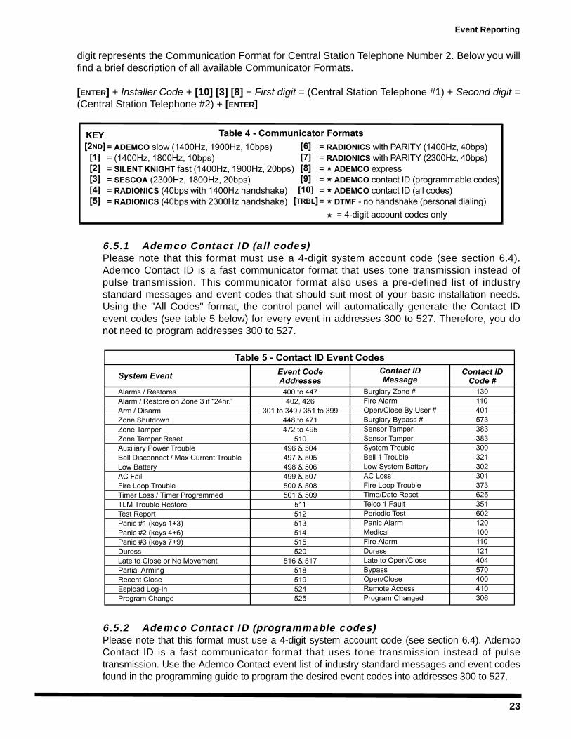
digit represents the Communication Format for Central Station Telephone Number 2. Below you willfind a brief description of all available Communicator Formats.
[ENTER] + Installer Code + [10] [3] [8] + First digit = (Central Station Telephone #1) + Second digit =(Central Station Telephone #2) + [ENTER]
6.5.1 Ademco Contact ID (all codes)Please note that this format must use a 4-digit system account code (see section 6.4).Ademco Contact ID is a fast communicator format that uses tone transmission instead ofpulse transmission. This communicator format also uses a pre-defined list of industrystandard messages and event codes that should suit most of your basic installation needs.Using the "All Codes" format, the control panel will automatically generate the Contact IDevent codes (see table 5 below) for every event in addresses 300 to 527. Therefore, you donot need to program addresses 300 to 527.
6.5.2 Ademco Contact ID (programmable codes)Please note that this format must use a 4-digit system account code (see section 6.4). AdemcoContact ID is a fast communicator format that uses tone transmission instead of pulsetransmission. Use the Ademco Contact event list of industry standard messages and event codesfound in the programming guide to program the desired event codes into addresses 300 to 527.
Event Reporting
24
6.5.3 Ademco Express This high-speed reporting format communicates 2-digit (00 to FF) events programmed ataddresses 300 to 527 at a speed of 2 seconds per event. Unlike other Ademco formats, theContact ID Event Codes are not used. Please note this format must use a 4-digit systemaccount code (see section 6.4).
6.5.4 DTMF - no handshakeThis format is the same as the Ademco contact ID (programmable codes) except there is noverification of the report code sent (no handshake). Use this format in reporting situations where acentral station receiver is not connected to the telephone number. It is also useful for personalreporting where a "handshake" is not required. For example, in "double reporting" mode, the firstcentral station number can be connected to a receiver, while the second can be used for personalreporting using "no handshake" format. The panel will make two attempts to call the "no handshake"number. Please note this format must use a 4-digit system account code (see section 6.4).
6.5.5 Standard Pulse FormatsThe control panel supports the following pulse reporting formats (see table 4 on the previouspage): Ademco slow, Silent Knight, Sescoa, and Radionics.
6.6 Reporting Event CodesStreamline - Sections 11 to 67 Hexa Programming - Addresses 300-527An Event Code is a 2-digit hexadecimal value, consisting of numbers from 00-FF. Each address between300 and 527 represents a specific event, as described below and in the "Programming Guide". When anevent occurs in the system, the control panel will attempt to transmit the 2-digit Event Code programmedat the corresponding address to the central station. The method of Event Code transmission isdependent on the Communicator Formats (see section 6.5) and the Reporting Options (see section 6.1).
Note:You do not need to program addresses 300-527 if using the Ademco Contact I.D. (all codes)format. If you plan to program most of the event code addresses, we suggest you use the HexaStreamlined Section Programming Method as described in section 4.2.2. Otherwise, use the HexaProgramming Method as described in section 4.2.1.
6.6.1 Arming CodesStreamline - Sections 11 to 23 Hexa Programming - Addresses 300-349Whenever the system is armed, the control panel will send the programmed event code tothe Central Station identifying who or how the system was armed.
6.6.2 Disarming CodesStreamline - Sections 23 to 35 Hexa Programming - Addresses 350-399Whenever the system is disarmed, the control panel will send the programmed event code tothe Central Station identifying who disarmed the system.
6.6.3 Alarm CodesStreamline - Section 36 to 41 Hexa Programming - Addresses 400-423Whenever an alarm occurs, the control panel will send the programmed event code to theCentral Station identifying which zone generated an alarm.
6.6.4 Restore CodesStreamline - Sections 42 to 47 Hexa Programming - Addresses 424-447The control panel will send the programmed event code to the Central Station as soon as thezone closes after having generated an alarm or as soon as the zone closes after bell cut-off.For more information, please see Report Zone Restore Options in section 6.11.
Event Reporting
25
6.6.5 Shutdown CodesStreamline - Sections 48 to 53 Hexa Programming - Addresses 448-471If the Auto Zone Shutdown (see section 7.11.1) feature is enabled, the control panel will sendthe programmed event code to the Central Station identifying which zones were shutdown.
6.6.6 Tamper/Trouble CodesStreamline - Sections 54 to 56 Hexa Programming - Addresses 472-483If the Tamper/Wire Fault Recognition Options are disabled (see section 10.7), the controlpanel will never transmit these event codes. Otherwise, whenever a tamper occurs on azone, the control panel will send the programmed Event Code to the Central Station. WithAdvanced Technology Zoning (ATZ) enabled (see section 7.2) each Tamper Code addresswill represent two zones (e.g. Tamper 1 = zones 1 & 2, Tamper 2 = zones 3 & 4, etc.). Thecontrol panel will send the programmed Event Code when a tamper occurs on either zone.
6.6.7 Trouble/Restore CodesStreamline - Sections 60 to 63 Hexa Programming - Addresses 496-511Each of the these addresses represent a specific trouble or restore condition. The controlpanel will report the appropriate event code to the central station when one of the followingconditions occurs or after the condition has returned to normal.
496 - Max. Auxiliary Current: the current draw from auxiliary is 1.1A.504 - Max. Auxiliary Current Restore 497 - Bell Disconnect/Max. Bell Current: Bell is disconnected or Bell current is 3A.505 - Bell Disconnect Restore: No restore code for bell current.498 - Battery Disconnect/Low Voltage: Battery disconnected or battery voltage 10.5V.506 - Battery Disconnect/Low Voltage Restore499 - Power Failure: Voltage on AC input is 12.5V.507 - Power Failure Restore500 - Fire Loop Trouble: A tamper occurs on a fire zone (Zone 3/24hr.).508 - Fire Loop Trouble Restore501 - Timer Loss: The control panel detects a loss in the panel timer.509 - Timer Programmed502 to 503 - Reserved for Future Use510 - All Tamper/Trouble Codes (see section 6.6.6) have returned to "normal".511 - TLM Trouble Restore: Telephone line has restored after the TLM (see section 10.1)
has detected the loss of a telephone line.
6.6.8 Special CodesStreamline - Sections 64 to 67 Hexa Programming - Addresses 512-527Each address represents a special condition in the system. When one of these specialconditions occur, the control panel will report the event code associated with the address.
512 - Test Report: The test report has been activated either manually (see section 6.8) orautomatically (see section 6.7).
513 - Panic 1: Keys [1] and [3] or a PS1 is pressed to activate a Panic 1 alarm 514 - Panic 2: Keys [4] and [6] are pressed to activate a Panic 2 alarm 515 - Panic 3: Keys [7] and [9] are pressed to activate a Panic 3 alarmFor more information on Keypad Panic Options see section 10.4
516 - Late To Close: "Timed" Auto Arming is enabled (see section 8.1) and the system hasnot automatically armed itself at the specified time.
517 - No Movement: "No Movement" Auto Arming is enabled (see section 8.2) and nomovement has occurred for the designated amount of time.
Event Reporting

26
518 - Partial Arming: Whenever the system is "Away" armed, "Stay" armed, or armedwhile one or more zones are bypassed.
519 - Recent Close: An alarm occurs shortly after the system has been armed, refer toRecent Close Delay in section 6.10.
520 - Duress: The Duress feature is enabled (see section 3.4) and a User disarms thesystem using the User Code #48.
524 - Log-In (Espload): Espload software is used to communicate with the Control Panel.525 - Program Change: The installer code is used to enter the programming mode521 to 523 - Reserved for Future Use526 to 527 - Reserved for Future Use
6.7 Auto Test ReportDecimal Programming Addresses 046-048Default: Auto Test Report DisabledThe report code programmed at address 512 will be reported to the central station after the numberof days programmed at address 046 and the time programmed at address 047 (hours) and 048(minutes) has elapsed. To disable this feature, program 000 at address 046. Also note that if[2ND][2ND] is programmed at address 512 nothing will be reported.
[ENTER] + Installer Code + [10] [4] [6] + 2 digits (days) + [10] [4] [7] + 2 digits (hours) + [10] [4] [8]+ 2 digits (minutes) + [ENTER]
6.8 Manual Test ReportKey Access Programming key [BYP]Activating the manual test report will send the Event Code programmed at address 512 to theCentral Station.
[ENTER] + (Installer, Master, or User 1 Code) + [BYP] + [ENTER]
6.9 Power Failure Report DelayDecimal Programming Addresses 054Default: 30 minutesAfter a power failure, the control panel will delay transmission of the event code programmed ataddress 499 by the period programmed at this address (001 to 255 minutes).
[ENTER] + Installer Code + [10] [5] [4] + 3-digit decimal value (001-255) + [ENTER]
6.10 Recent Close DelayDecimal Programming Addresses 060Default: Recent Close Delay DisabledThe system will transmit the recent close event code programmed at address 519 if after armingthe system, an alarm occurs within the period programmed at this address (001 to 255 minutes).Program 000 into address 060 to disable this feature.
[ENTER] + Installer Code + [10] [6] [10] + 3-digit decimal value (001-255) + [ENTER]
Event Reporting
27
6.11 Report Zone Restore OptionsFeature Select Programming Address 088; key [BYP]Default: Zone Restore Codes Transmit on Bell Cut-OffWith the [BYP] key "Off", the report codes programmed at addresses 424-447 (see Restore Codes insection 6.6.4) will only transmit if the zone has returned to normal after bell cut-off (see section 8.11).With the [BYP] key "On", the codes will transmit as soon as the zone returns to normal (zone closure).
Key [BYP] "Off": Report on Bell Cut-OffKey [BYP] "On": Report on Zone Closure [ENTER] + Installer Code + [10] [8] [8] + [BYP] On/Off + [ENTER]
6.12 Report Code Disarming OptionsFeature Select Programming Address 088; key [TRBL]Default: Disarming Codes Transmit on User DisarmingWith the [TRBL] key "OFF", the Disarming Codes programmed at addresses 350-399 (see insection 6.6.2) will transmit whenever a User disarms the system. With the [TRBL] key "ON", thecontrol panel will transmit these codes when a User disarms a system in alarm.
Key [TRBL] "Off": Always Report DisarmKey [TRBL] "On": Report Disarm Only After Alarm [ENTER] + Installer Code + [10] [8] [8] + [TRBL] On/Off + [ENTER]
Event Reporting
28
Zone Definitions
ZONE DEFINITIONS

29
7.1 Zone SpeedDecimal Programming Address 053Default: 600mSThe zone speed applies to all zones whether the system is armed or disarmed. The zone speeddefines how quickly the control panel will respond to an open zone. The control panel will notdisplay and/or respond to an open zone until the programmed zone speed elapses. All other zonedefinitions and options do not come into effect until the zone speed has elapsed.
Example: The system is armed and the zone speed is set for 1.2 seconds. A zone opensand closes in less than 1.2 seconds the control panel will not respond (i.e. no reporting,no alarm and no display on keypad).
The zone speed can be set from 15ms to 3.8s (001 to 255 X 15ms). This feature prevents anymomentary glitches in the system from causing an alarm or unnecessary reporting.
[ENTER] + Installer Code + [10] [5] [3] + 3 digit decimal value (001-255) + [ENTER]
7.2 Advanced Technology Zoning (ATZ)Feature Select Programming Address 090, key [8]Default: ATZ DisabledThis feature is not available on the 748 EXPRESS control panels. Enabling the ATZ feature allowsyou to install two detection devices per zone input. Each detection device will have its own zone numberand each will transmit a separate alarm code that will display on the keypad. For information on how toconnect the detection devices and how the panel recognizes them, please refer to section 2.10.
Key [8] "Off": ATZ DisabledKey [8] "On": ATZ Enabled [ENTER] + Installer Code + [10] [9] [10] + [8] On/Off + [ENTER]
7.3 IntellizonesFeature Select Programming Addresses 092 & 094, keys [1] to [12]If an alarm condition occurs on a zone identified as Intellizone, the control panel will trigger a timerand will not generate an alarm until one of the following conditions occurs within a specified period(see Intellizone Time Delay below):
An alarm condition occurs on another zone during intellizone time delay.The zone that is in alarm has restored and re-occurred during intellizone time delay.The zone that is in alarm remains in alarm the entire intellizone time delay.
Note: Intellizone timer will only begin after the zone speed period has elapsed (see section 7.1).
Do not use the Intellizone feature on zones programmed with any Entry Delay! An alarm mayoccur when disarming the system.
7.3.1 Intellizone Time DelayDecimal Programming Address 057Default: 48 secondsYou can set the Intellizone Time Delay between 010 and 255 seconds. Before an Intellizone cangenerate an alarm, one of three conditions must occur during this time delay (see section 7.3).
[ENTER] + Installer Code + [10] [5] [7] + 3-digit decimal value (010-255) + [ENTER]
Zone Definitions
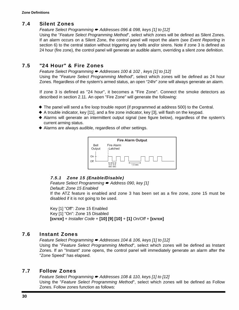
30
7.4 Silent ZonesFeature Select Programming Addresses 096 & 098, keys [1] to [12]Using the "Feature Select Programming Method", select which zones will be defined as Silent Zones.If an alarm occurs on a Silent Zone, the control panel will report the alarm (see Event Reporting insection 6) to the central station without triggering any bells and/or sirens. Note if zone 3 is defined as24 hour (fire zone), the control panel will generate an audible alarm, overriding a silent zone definition.
7.5 "24 Hour" & Fire ZonesFeature Select Programming Addresses 100 & 102 , keys [1] to [12]Using the "Feature Select Programming Method", select which zones will be defined as 24 hourZones. Regardless of the system’s armed status, an open “24hr” zone will always generate an alarm.
If zone 3 is defined as "24 hour", it becomes a "Fire Zone". Connect the smoke detectors asdescribed in section 2.11. An open "Fire Zone" will generate the following:
The panel will send a fire loop trouble report (if programmed at address 500) to the Central.A trouble indicator, key [11], and a fire zone indicator, key [3], will flash on the keypad.Alarms will generate an intermittent output signal (see figure below), regardless of the system'scurrent arming status.Alarms are always audible, regardless of other settings.
7.5.1 Zone 15 (Enable/Disable)Feature Select Programming Address 090, key [1]Default: Zone 15 EnabledIf the ATZ feature is enabled and zone 3 has been set as a fire zone, zone 15 must bedisabled if it is not going to be used.
Key [1] "Off": Zone 15 EnabledKey [1] "On": Zone 15 Disabled [ENTER] + Installer Code + [10] [9] [10] + [1] On/Off + [ENTER]
7.6 Instant ZonesFeature Select Programming Addresses 104 & 106, keys [1] to [12]Using the "Feature Select Programming Method", select which zones will be defined as InstantZones. If an "Instant" zone opens, the control panel will immediately generate an alarm after the"Zone Speed" has elapsed.
7.7 Follow ZonesFeature Select Programming Addresses 108 & 110, keys [1] to [12]Using the "Feature Select Programming Method", select which zones will be defined as FollowZones. Follow zones function as follows:
Zone Definitions
31
If a follow zone opens and no entry delay zones have been triggered; the control panel willimmediately generate an alarm after the zone speed has elapsed.If a follow zone opens during another zone's entry delay period, the control panel will wait untilthe end of the entry delay period before generating an alarm.If a follow zone opens when more than one entry delay zone has been triggered, the panel willwait until the end of the entry delay zone that opened first before generating an alarm.
7.8 Entry Delay 1Decimal Programming Address 050Default: 45 secondsAny zone that has not been identified as either Instant Zones, Follow Zones, Entry Delay 2, or "24Hour" & Fire Zones (see above) will automatically default to Delay 1. You can program the Delay 1period between 001 and 255 seconds into address 050. If a zone defined as Delay 1 opens in anarmed system, the control panel will wait the pre-programmed period before generating an alarm.This provides the users the time required to disarm the system when entering the protected area.
[ENTER] + Installer Code + [10] [5] [10] + 3-digit decimal value (001-255) + [ENTER]
7.9 Entry Delay 2Feature Select Programming Addresses 112 & 114, keys [1] to [12]Using the "Feature Select Programming Method", select which zones will be defined as EntryDelay 2 Zones. If a zone defined as Delay 2 opens in an armed system, the control panel will waitthe Entry Time Delay 2 (see below) period before generating an alarm. This provides the users thetime required to disarm the system when entering the protected area.
7.9.1 Entry Time Delay 2Decimal Programming Address 051Default: 45 secondsThis applies to all zones defined as Delay 2 (see Entry Delay 2 above). You can program theDelay 2 between 001 and 255 seconds.
[ENTER] + Installer Code + [10] [5] [1] + 3-digit decimal value (001-255) + [ENTER]
7.10 PartitioningFeature Select Programming Address 086, key [8]This feature divides the alarm system into two distinct systems, identified as "System A" and"System B". You can assign each zone to System A, System B, both systems, or neither system.Partitioning works as follows:
Zones assigned to System A, will arm/disarm when the system is "System A Armed/Disarmed".Zones assigned to System B, will arm/disarm when the system is "System B Armed/Disarmed".Zones assigned to both systems ("dual area") will arm when the system is either "System AArmed", "System B Armed" or when both systems are armed and will disarm only when bothsystems disarm.Zones not identified to any system ("common area") will arm only when the system is both"System A Armed" and "System B Armed" and will only disarm when at least one of the twosystems disarms.
Zone Definitions
32
For more information on arming and disarming partitions, see section 11.5. Also see Code Priorityin section 8.12.
7.10.1 "System A"/Stay ZonesFeature Select Programming Addresses 116 & 118, keys [1] to [12]Using the "Feature Select Programming Method", select which zones will be assigned to"System A" or if the system isn’t partitioned which zones will be identified as Stay Zones. Fordetails on "System A" zones refer to Partitioning above. For details on Stay Arming seesection 11.4.
7.10.2 "System B" ZonesFeature Select Programming Address 120 & 122, keys [1] to [12]Using the "Feature Select Programming Method", select which zones will be assigned to"System B". For details on "System B" zones refer to Partitioning above.
7.11 Bypass Enabled ZonesFeature Select Programming Addresses 124 & 126, keys [1] to [12]Using the "Feature Select Programming Method", select which zones will be defined as BypassEnabled. Only zones defined as bypass enabled can be used for Manual Zone Bypassing (section11.9) or during Auto Zone Shutdown (see below).
7.11.1 Auto Zone ShutdownFeature Select Programming Address 086 key [TRBL]Default: Auto Zone Shutdown DisabledThe control panel will automatically bypass any "Bypass Enabled Zones" which initiate 5consecutive alarms in the same-armed period. Therefore, the zone will no longer generate analarm. After the control panel has bypassed a zone, it will report an event code to the CentralStation if programmed at addresses 448-461.
This feature is also a function of the Report Zone Restore Options (see section 6.11). If thisoption is set for report zone restore on bell cut-off, the zone will only be bypassed after thebell or siren has cut-off 5 consecutive times in the same armed period. While if the option isset for report zone on zone closure, the zone will be bypassed when the zone has openedand closed 5 consecutive times in one armed period.
Key [TRBL] "Off": Auto Zone Shutdown DisabledKey [TRBL] "On": Auto Zone Shutdown Enabled[ENTER] + Installer Code + [10] [8] [6] + [TRBL] On/Off + [ENTER]
7.12 EOL Zones (Enabled/Disabled)Feature Select Programming Address 088; key [MEM]If the system requires the use of 1K end of line resistors on zone input terminals, enable thisfeature (see Zone Connections in sections 2.8 to 2.10).
Key [MEM] "Off": Input Zones use EOL ResistorsKey [MEM] "On": Input Zones do not use EOL Resistors[ENTER] + Installer Code + [10] [8] [8] + [MEM] On/Off + [ENTER]
Zone Definitions
33
7.13 Keypad Zone 1 SupervisionFeature Select Programming Address 090, key [11]Default: DisabledWhen using a keypad defined as keypad zone 1, enable this feature. When enabled, the controlpanel will verify the presence of a keypad and the keypad zone. For more information see KeypadZone Connections in section 2.8.
Key [11] "Off": Keypad Zone 1 Disabled Key [11] "On": Keypad Zone 1 Enabled[ENTER] + Installer Code + [10] [9] [10] + [11] On/Off + [ENTER]
7.14 Keypad Zone 2 SupervisionFeature Select Programming Address 090, key [12]Default: DisabledWhen using a keypad defined as keypad zone 2, enable this feature. When enabled, the controlpanel will verify for the presence of a keypad and the keypad zone. For more information seeKeypad Zone Connections in section 2.8.
Key [12] "Off": Keypad Zone 2 Disabled Key [12] "On": Keypad Zone 2 Enabled[ENTER] + Installer Code + [10] [9] [10] + [12] On/Off + [ENTER]
Zone Definitions
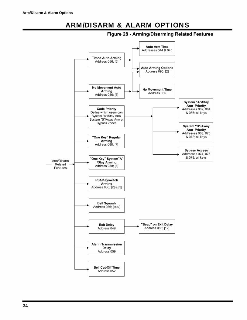
34
ARM/DISARM & ALARM OPTIONS
Arm/Disarm & Alarm Options
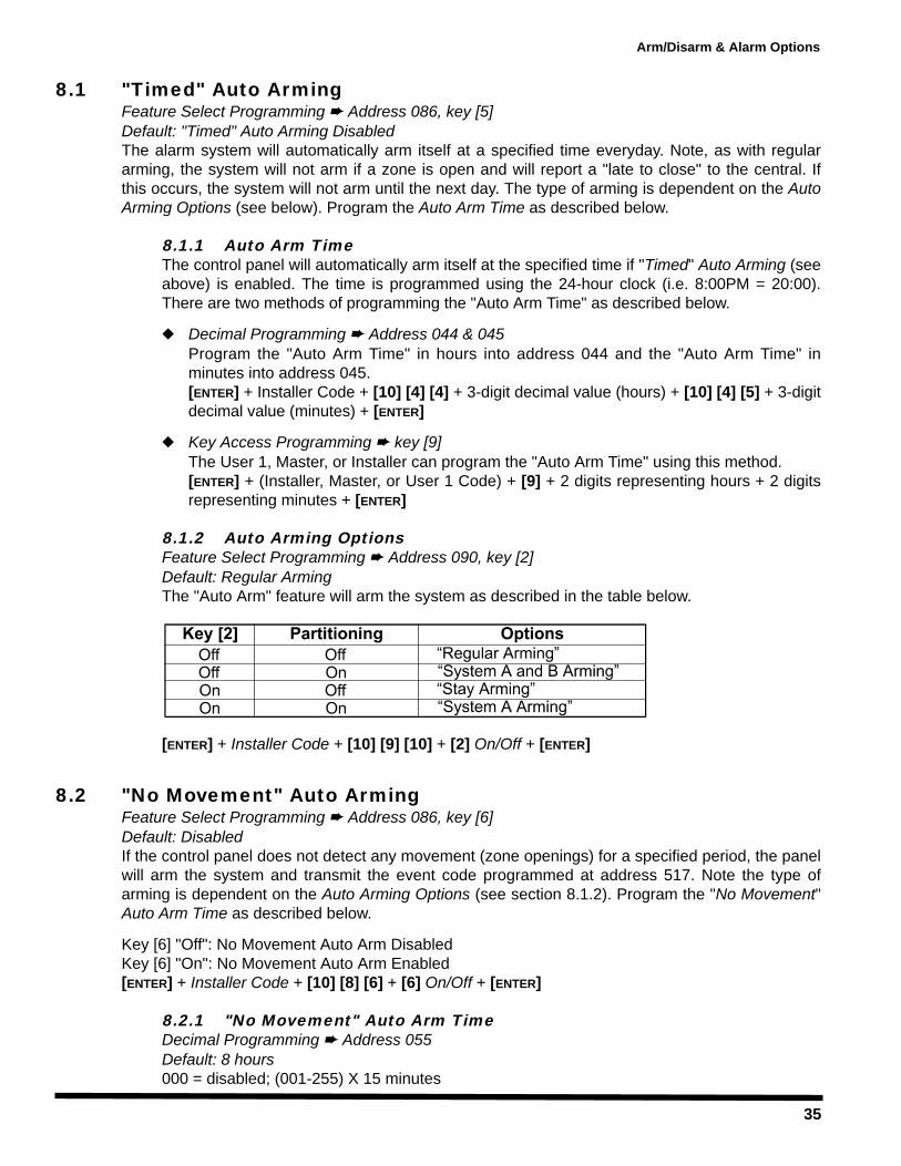
35
Arm/Disarm & Alarm Options
8.1 "Timed" Auto ArmingFeature Select Programming Address 086, key [5]Default: "Timed" Auto Arming DisabledThe alarm system will automatically arm itself at a specified time everyday. Note, as with regulararming, the system will not arm if a zone is open and will report a "late to close" to the central. Ifthis occurs, the system will not arm until the next day. The type of arming is dependent on the AutoArming Options (see below). Program the Auto Arm Time as described below.
8.1.1 Auto Arm TimeThe control panel will automatically arm itself at the specified time if "Timed" Auto Arming (seeabove) is enabled. The time is programmed using the 24-hour clock (i.e. 8:00PM = 20:00).There are two methods of programming the "Auto Arm Time" as described below.
Decimal Programming Address 044 & 045Program the "Auto Arm Time" in hours into address 044 and the "Auto Arm Time" inminutes into address 045.[ENTER] + Installer Code + [10] [4] [4] + 3-digit decimal value (hours) + [10] [4] [5] + 3-digitdecimal value (minutes) + [ENTER]
Key Access Programming key [9]The User 1, Master, or Installer can program the "Auto Arm Time" using this method.[ENTER] + (Installer, Master, or User 1 Code) + [9] + 2 digits representing hours + 2 digitsrepresenting minutes + [ENTER]
8.1.2 Auto Arming OptionsFeature Select Programming Address 090, key [2]Default: Regular ArmingThe "Auto Arm" feature will arm the system as described in the table below.
[ENTER] + Installer Code + [10] [9] [10] + [2] On/Off + [ENTER]
8.2 "No Movement" Auto ArmingFeature Select Programming Address 086, key [6]Default: DisabledIf the control panel does not detect any movement (zone openings) for a specified period, the panelwill arm the system and transmit the event code programmed at address 517. Note the type ofarming is dependent on the Auto Arming Options (see section 8.1.2). Program the "No Movement"Auto Arm Time as described below.
Key [6] "Off": No Movement Auto Arm DisabledKey [6] "On": No Movement Auto Arm Enabled[ENTER] + Installer Code + [10] [8] [6] + [6] On/Off + [ENTER]
8.2.1 "No Movement" Auto Arm TimeDecimal Programming Address 055Default: 8 hours000 = disabled; (001-255) X 15 minutes
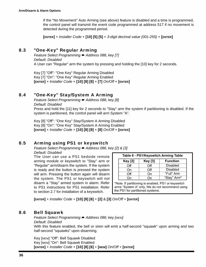
36
If the "No Movement" Auto Arming (see above) feature is disabled and a time is programmed,the control panel will transmit the event code programmed at address 517 if no movement isdetected during the programmed period.
[ENTER] + Installer Code + [10] [5] [5] + 3-digit decimal value (001-255) + [ENTER]
8.3 "One-Key" Regular ArmingFeature Select Programming Address 088, key [7]Default: DisabledA User can "Regular" arm the system by pressing and holding the [10] key for 2 seconds.
Key [7] "Off": "One Key" Regular Arming DisabledKey [7] "On": "One Key" Regular Arming Enabled[ENTER] + Installer Code + [10] [8] [8] + [7] On/Off + [ENTER]
8.4 "One-Key" Stay/System A ArmingFeature Select Programming Address 088, key [8]Default: DisabledPress and hold the [11] key for 2 seconds to "Stay" arm the system if partitioning is disabled. If thesystem is partitioned, the control panel will arm System "A".
Key [8] "Off": "One Key" Stay/System A Arming DisabledKey [8] "On": "One Key" Stay/System A Arming Enabled[ENTER] + Installer Code + [10] [8] [8] + [8] On/Off + [ENTER]
8.5 Arming using PS1 or keyswitchFeature Select Programming Address 086, key [2] & [3]Default: DisabledThe User can use a PS1 bedside remotearming module or keyswitch to "Stay" arm or"Regular" arm/disarm the system. If the systemis ready and the button is pressed the systemwill arm. Pressing the button again will disarmthe system. The PS1 or keyswitch will notdisarm a “Stay” armed system in alarm. Referto PS1 instructions for PS1 installation. Referto section 2.7 for installation of a keyswitch.
[ENTER] + Installer Code + [10] [8] [6] + [2] & [3] On/Off + [ENTER]
8.6 Bell SquawkFeature Select Programming Address 086; key [MEM]Default: DisabledWith this feature enabled, the bell or siren will emit a half-second "squawk" upon arming and twohalf-second "squawks" upon disarming.
Key [MEM] "Off": Bell Squawk DisabledKey [MEM] "On": Bell Squawk Enabled[ENTER] + Installer Code + [10] [8] [6] + [MEM] On/Off + [ENTER]
Arm/Disarm & Alarm Options

37
8.7 Exit DelayDecimal Programming Address 049Default: 60 secondsExit Delay applies to all zones. This option determines how much time the user has to leave theprotected area before the system arms after entering a valid access code. You can program theExit Delay from 001 to 255 sec.
[ENTER] + Installer Code + [10] [4] [9] + 3 digit decimal value (001-255) + [ENTER]
8.8 Beep on Exit delayFeature Select Programming Address 088, key [12]Default: DisabledWith this feature enabled, the keypad will emit an intermittent "beep" during the programmed exitdelay period (except when in "stay" arming). The frequency of intermittent beeps increases duringthe last 10 seconds of the exit delay period. For more information on Exit Delay refer to section 8.7.
Key [12] "Off": Beep on Exit Delay DisabledKey [12] "On": Beep on Exit Delay Enabled[ENTER] + Installer Code + [10] [8] [8] + [12] On/Off + [ENTER]
8.9 Alarm Transmission DelayDecimal Programming Address 059This time limit, set between 5 and 63 seconds, is the delay period before reporting an alarm to thecentral station after an alarm condition. During this period, disarming the system will cancel allpending alarms and send the restore codes. Programming 000-004 in this address disables thisfeature. Maximum 30 seconds on UL listed systems.
[ENTER] + Installer Code + [10] [5] [9] + 3-digit decimal value (005-063) + [ENTER]
8.10 Silent Zones & Silent Panics OptionFeature Select Programming Address 086, key [9]If the [9] key is on, silent zones or silent panics only transmit a report to the central station. Thesystem will not indicate an alarm and will not have to be disarmed. Although, the control panel can still activate a PGM. If a keypad panic has been defined as audible,the control panel will override this option.
Key [9] "Off": Silent Zones & Silent Panics generate a silent alarmKey [9] "On": Silent Zones & Silent Panics generate a report only[ENTER] + Installer Code + [10] [8] [6] + [9] On/Off + [ENTER]
8.11 Bell Cut-Off TimeDecimal Programming Address 052Default: 5 minutesAfter an audible alarm, the bell or siren will stop after the programmed time has elapsed.
[ENTER] + Installer Code + [10] [5] [2] + 3-digit decimal value (001-255) minutes + [ENTER]
Arm/Disarm & Alarm Options
38
8.12 Code PriorityFeature Select Programming Address 062-078, [all] keysIn order for a user to arm a partitioned system, to "Stay" arm, to "Away" arm or to manually bypasszones, the user must be given code priority. Using the "Feature Select Programming Method",identify which arming method each user can use. For more information on arming/disarmingmethods please refer to section 11. Also refer to the “Programming Guide” for additionalinformation.
Partitioning Disabled:Addresses 062-066: Selected keys indicate which user codes can activate "Stay" arming.Addresses 068-072: Selected keys indicate which user codes can activate "Away" arming.Addresses 074-078: Selected keys indicate which user codes can "Bypass" zones.
Partitioning Enabled:Addresses 062-066: Selected keys indicate which user codes can arm “System A".Addresses 068-072: Selected keys indicate which user codes can arm “System B".Addresses 074-078: Selected keys indicate which user codes can "bypass" zones.
Arm/Disarm & Alarm Options
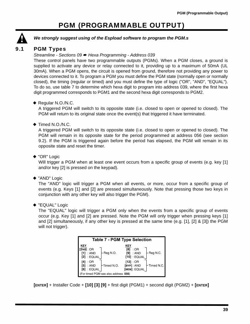
39
PGM (PROGRAMMABLE OUTPUT)We strongly suggest using of the Espload software to program the PGM.s
9.1 PGM TypesStreamline - Sections 09 Hexa Programming - Address 039These control panels have two programmable outputs (PGMs). When a PGM closes, a ground issupplied to activate any device or relay connected to it, providing up to a maximum of 50mA (UL30mA). When a PGM opens, the circuit is opened from ground, therefore not providing any power todevices connected to it. To program a PGM you must define the PGM state (normally open or normallyclosed), the timing (regular or timed) and you must define the type of logic ("OR", "AND", "EQUAL").To do so, use table 7 to determine which hexa digit to program into address 039, where the first hexadigit programmed corresponds to PGM1 and the second hexa digit corresponds to PGM2.
Regular N.O./N.C.A triggered PGM will switch to its opposite state (i.e. closed to open or opened to closed). ThePGM will return to its original state once the event(s) that triggered it have terminated.
Timed N.O./N.C.A triggered PGM will switch to its opposite state (i.e. closed to open or opened to closed). ThePGM will remain in its opposite state for the period programmed at address 056 (see section9.2). If the PGM is triggered again before the period has elapsed, the PGM will remain in itsopposite state and reset the timer.
"OR" LogicWill trigger a PGM when at least one event occurs from a specific group of events (e.g. key [1]and/or key [2] is pressed on the keypad).
"AND" LogicThe "AND" logic will trigger a PGM when all events, or more, occur from a specific group ofevents (e.g. Keys [1] and [2] are pressed simultaneously. Note that pressing those two keys inconjunction with any other key will also trigger the PGM).
"EQUAL" LogicThe "EQUAL" logic will trigger a PGM only when the events from a specific group of eventsoccur (e.g. Key [1] and [2] are pressed. Note the PGM will only trigger when pressing keys [1]and [2] simultaneously, if any other key is pressed at the same time (e.g. [1], [2] & [3]) the PGMwill not trigger).
[ENTER] + Installer Code + [10] [3] [9] + first digit (PGM1) + second digit (PGM2) + [ENTER]
PGM (Programmable Output)

40
9.2 PGM Timer SettingDecimal Programming Address 056Default: 5 secondsYou can program the PGM Timer from 1 to 127 seconds or 1 to 127 minutes. The PGM Timerapplies to both PGMs. To determine the 3-digit decimal value, do the following:
To program seconds, the required time is respective to the decimal value1 second = 001, 55 seconds = 055, 127 seconds = 127.To program the minutes add the required minutes to 128:5 minutes: 128 + 5 = 133127 minutes: 128 +127 = 255
[ENTER] + Installer Code + [10] [5] [6] + 3-digit decimal value (001-255) + [ENTER]
9.3 PGM OptionsStreamline - Section 10 Hexa Programming - Addresses 040 to 043The PGM options define which sequence of events will trigger the PGM. The PGM options arevirtually endless. Therefore, to list them in the manual is impractical. Table 8, contains a list of themost commonly used PGM options with the required 2-digit data for each address. If other optionsare required, you can fax your requests to Paradox Technical Support, you can visit our web site athttp://www.paradox.ca. or the 2-digit data can be derived using the Espload Software as follows:
1) From the "Main Menu" select Accounts2) Select a current Account or create a new one3) Press the key until page 9 appears4) Using the arrow keys and space bar select the PGM options, state, logic and type for the PGM5) Press the key to view the "Hexadecimal Mode". This mode will display the 2-digit data for
addresses 039 to 043.6) Record these numbers and program them into the control panel or use the Espload Software to
download the data directly to the control panel.
If you do not have a copy of the Espload Software, you can obtain a FREE copy from your localParadox distributor.
PGM (Programmable Output)

41
OTHER OPTIONS
10.1 Telephone Line Monitoring (TLM)Feature Select Programming Address 086, key [2ND] & [1]Default: TLM DisabledWhen enabled, the system verifies the existence of a telephone line every 4 seconds. After eachsuccessful test, the dialer LED (green light) on the control panel flashes briefly. If the test fails theLED flashes on and off until the control panel detects the telephone line again. TLM will activate atrouble when less than 3 volts is detected in four consecutive tests. Note: when the dialer detects a telephone ring, the TLM test stops for 1 minute.
There are three TLM options, which are set as indicated in table 9:
1) OFF/ON: Line test failure will generate a troubleindication; key [10] will illuminate on the keypad.
2) ON/OFF: Line test failure will generate a troubleindication and an alarm if the system is armed.
3) ON/ON: Line test failure will generate a troubleindication and cause a silent zone or a silent panicalarm to switch to audible mode.
[ENTER] + Installer Code + [10] [8] [6] + [2ND] & [1] On/Off + [ENTER]
10.2 Dialing OptionsFeature Select Programming Address 086, key [7]Default: Pulse DialingYou can program the control panel to use the pulse dialing or tone/DTMF dialing format.
Key [7] "Off": Pulse Dialing Key [7] "On": Tone/DTMF Dialing[ENTER] + Installer Code + [10] [8] [6] + [7] On/Off + [ENTER]
10.3 Dialing Pulse RatesFeature Select Programming Address 086, key [10]This selection reflects the ratio between "pulse" time and "quiet" time. Select Pulse Europe for a1:2 ratio and select Pulse USA for 1:1.5. Must be set to pulse dialing mode, refer to section 10.2.
Key [10] "Off": Pulse Europe 1:2Key [10] "On": Pulse USA 1:1.5[ENTER] + Installer Code + [10] [8] [6] + [10] On/Off + [ENTER]
10.4 Keypad Panic OptionsFeature Select Programming Address 088 keys [1] to [6]This feature will generate an alarm when the User presses two specific keys on the keypadsimultaneously for 2 seconds as described below:
Key [1] "on" = Panic 1 (keys [1] and [3] or PS1) enabledKey [2] "on" = Panic 2 (keys [4] and [6]) enabledKey [3] "on" = Panic 3 (keys [7] and [9]) enabled
Other Options
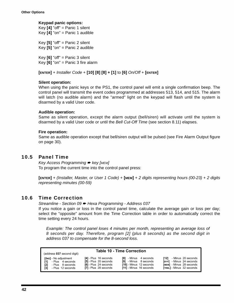
42
Keypad panic options:Key [4] "off" = Panic 1 silentKey [4] "on" = Panic 1 audible
Key [5] "off" = Panic 2 silentKey [5] "on" = Panic 2 audible
Key [6] "off" = Panic 3 silentKey [6] "on" = Panic 3 fire alarm
[ENTER] + Installer Code + [10] [8] [8] + [1] to [6] On/Off + [ENTER]
Silent operation:When using the panic keys or the PS1, the control panel will emit a single confirmation beep. Thecontrol panel will transmit the event codes programmed at addresses 513, 514, and 515. The alarmwill latch (no audible alarm) and the "armed" light on the keypad will flash until the system isdisarmed by a valid User code.
Audible operation:Same as silent operation, except the alarm output (bell/siren) will activate until the system isdisarmed by a valid User code or until the Bell Cut-Off Time (see section 8.11) elapses.
Fire operation:Same as audible operation except that bell/siren output will be pulsed (see Fire Alarm Output figureon page 30).
10.5 Panel TimeKey Access Programming key [MEM]To program the current time into the control panel press:
[ENTER] + (Installer, Master, or User 1 Code) + [MEM] + 2 digits representing hours (00-23) + 2 digitsrepresenting minutes (00-59)
10.6 Time CorrectionStreamline - Section 09 Hexa Programming - Address 037 If you notice a gain or loss in the control panel time, calculate the average gain or loss per day;select the "opposite" amount from the Time Correction table in order to automatically correct thetime setting every 24 hours.
Example: The control panel loses 4 minutes per month, representing an average loss of8 seconds per day. Therefore, program [2] (plus 8 seconds) as the second digit inaddress 037 to compensate for the 8-second loss.
Other Options

43
10.7 Tamper/Wire Fault Recognition OptionsFeature Select Programming Address 088, keys [10] to [11]If the control panel detects an open or a short on a zone when the system is armed, regardless ofthe tamper/wire settings it will always generate an alarm and trouble indicator (key [9]). Alarms willbe audible or silent depending on individual zone definitions. If an open or short occurs on adisarmed system, the control panel will generate an incident depending on the following settings:
"Tamper/wire" disabledTamper/wiring failure recognition is disabled. Not permitted on UL listed systems.
"Trouble" enabledTamper/wiring failure will generate a trouble indicator (key [9]) and a trouble report code (seeTamper/Trouble Codes in section 6.6.6.) when the system is disarmed.
"Silent alarm" enabled Tamper/wiring failure will generate a trouble indicator (key [9]), a trouble report code (seeTamper/Trouble Codes in section 6.6.6.) and a silent alarm (no bells/sirens)
"Audible alarm" enabledTamper/wiring failure will generate a trouble indicator (key [9]), a trouble report code (seeTamper/Trouble Codes in section 6.6.6.) and an audible alarm.
Exception! When the zone definition is "24 hour", the tamper definition follows theaudible/silent alarm definition of the "24 hour" zone.
10.8 Tamper Bypass OptionsFeature Select Programming Address 090, key [6] With this option enabled, the control panel will not generate an alarm if a tamper is detected on abypassed zone while the system is armed. With this option disabled, the control panel will generatean alarm if a tamper is detected on a bypassed zone while the system is armed.
Key [6] "Off": Arm the system if Tamper on Bypassed ZoneKey [6] "On": Do not arm the system if Tamper on Bypassed Zone[ENTER] + Installer Code + [10] [9] [10] + [6] On/Off + [ENTER]
10.9 Installer Test ModeKey Access Programming key [8]The "Test Mode" will allow you to perform walk tests where the bell or siren will squawk, to indicateopened zones. To enter or exit the control panel "Test Mode" press:
[ENTER] + Installer Code + [8] to enable; press [8] again to disable
Other Options

44
10.10 Exclude Power Failure From Trouble DisplayFeature Select Programming Address 090, key [2ND]Default: DisabledExcludes the Power Failure, key [2], from the Trouble Display (see section 11.2).
10.11 Audible Trouble WarningFeature Select Programming Address 090, key [9]Default: DisabledTrouble conditions will emit an intermittent "beep" on the keypad. To silence the trouble warning,press the [TRBL] key.
10.12 Power Down ResetPerforming a power down reset will set the installer and master codes to factory default. Valuesentered at addresses 008-043, 062-124, 300-527, and all user codes will be erased ([2ND], [2ND]).Programmed values for all other addresses do not change. To perform a reset, the installer lockmust be disabled. To perform a power down reset perform the following:
1) Verify installer lock is disabled (see section 3.5)2) Remove the battery and AC power from the control panel.3) Set the reset jumper to on by placing a jumper on the reset pins of the control panel.4) Re-connect the AC and battery power to the control panel.5) Wait 10 seconds and remove the jumper.
Other Options
45
USER/KEYPAD FUNCTIONSThe innovative Esprit keypads take a new approach to security features and functions. Eachnumeral from 1 to 12 on the keypad respectively represents each zone from 1 to 12 on the controlpanel. When the [2ND] key flashes, press the [2ND] key to view zones 13 to 24, where keys [1] to[12] represent zones 13-24 respectively. When the zone light is "off", the status in the protectedzone is normal. If the zone light is "on", this means the zone is open. An LCD keypad will displaythe open zone numbers on the screen.
The green "ready" indicator on the keypad will illuminate when the status of all the zones is normal(zones are closed). Therefore, all protected windows and doors must be closed and motiondetectors must not detect any movement except those zones that have been bypassed.
Confirmation Beep: an intermittent series of beeps ("BEEP-BEEP-BEEP") indicates a successfulkeypad entry or system operation.
End/Rejection Beep: one long tone ("BEEEEEEEP") indicates incorrect keypad entry or unsuccessfulsystem operation.
11.1 Programming Master & User CodesThe Esprit control panels have one Master (00) code and up to 48 User (01-48) codes. Thedefault Master code is 474747. The Master code can arm the system using any arming method,can create/modify user codes and can perform Key Access Programming (see section 10.13). TheUser 1 code can create/modify access codes and perform key access programming. The accesscode consists of either 4 or 6-digits and each digit can be any value from 0 to 9.Note: do not enter [2ND] when programming the master code as this will invalidate the master code.
[ENTER] + Master or User 1 Code + 2-digit code number (00-48) + 4 or 6-digit access code + [ENTER]
11.2 Regular ArmingThis method, commonly used for day-to-day arming, will arm all the zones in the system. To do so,the keypad's green "READY" light must be illuminated, indicating that all zones are closed. All doorsand windows must be closed, and there can be no movement in areas monitored by motiondetectors. Once the "READY" light is on, a valid user access code must be entered. If a mistake ismade entering the code or if the "READY" indicator is not on when the code was entered, the keypadwill emit a "rejection beep" (BEEEEEEEP).
When the correct user access code is entered, the keypad will emit a "confirmation beep" (BEEP-BEEP-BEEP) and the red "ARM" indicator will illuminate. The "READY" light will flash and the keypad will"beep" during the exit delay period (see section 8.7). During the final 10 seconds of the exit delay,the keypad will "beep" and the "READY" indicator will flash at a faster rate. At the end of the exitdelay, the keypad will emit a "confirmation beep", the green "READY" indicator will extinguish and thered "ARM" indicator will remain illuminated to indicate that the system is armed.
11.2.1 "One-Key" Regular ArmingTo use this feature, enable the "One-Key" Regular Arming option (see section 8.3). When thegreen "READY" light is on, pressing and holding the [10] key for 2 seconds will arm all zones inthe system. This feature can be used to allow specific individuals like service personnel (i.e.cleaners, maintenance) to arm the system when leaving the protected area, without giving
User/Keypad Functions
46
them access to any other control panel operations. The use of a valid access code is stillrequired to disarm the system. For details on "Regular Arming", refer to section 11.2.
11.3 Away ArmingTo rapidly arm the system without having to wait for the green "READY" indicator, simply press the[AWAY] key followed by a valid access code. Once the exit delay expires, any open zones will beconsidered "deactivated" by the control panel. If while the system is armed a "deactivated" zone isclosed, the control panel will revert that zone to "active" status, generating an alarm if breached.
If a mistake is made entering the code, the keypad will emit a "rejection beep" (BEEEEEEEP). Whenthe correct user code is entered, the keypad will emit a "confirmation beep" (BEEP-BEEP-BEEP) andthe red "ARM" indicator will illuminate. The "READY" light and [AWAY] key will flash and the keypad will"beep" during the exit delay period (see section 8.7). During the final 10 seconds of the exit delay,the keypad will "beep" and the "READY" indicator and [AWAY] key will flash at a faster rate. At the endof the exit delay, the green "READY" indicator will stop flashing, the red "ARM" indicator will remainilluminated and the [AWAY] key will flash. If programmed at address 518, the control panel will send a"partial arm" report code to the central station. Note, to use this method the user must have "away"arming priority, see Code Priority in section 8.12)
11.4 Stay Arming"Stay" arming allows the user to remain in the protected area while partially arming the system.This means that they can stay in and move around the establishment, while certain designatedzones are armed. For example, entry/exit points like doors or windows, the basement, or perhapsall the zones on the perimeter of the establishment may be armed when going to sleep at night,while the other zones remain deactivated. To program which zones will be activated when "stayarming" the system refer to "System A"/Stay Zones in section 7.10.1. Also note that fire zones mustbe programmed as "stay zones"; they can not be bypassed.
Unlike regular arming, the green "READY" indicator does not have to be illuminated. Only doors andwindows programmed as "stay zones" must be closed, and there can be no movement in areasmonitored by motion detectors in "stay zones". To "stay" arm the system, press the [STAY] keyfollowed by a valid access code. If a mistake is made entering the code or if a "stay zone" is openwhen entering the code, the keypad will emit a "rejection beep" (BEEEEEEEP). After entering the correctuser access code, the keypad will emit a "confirmation beep" (BEEP-BEEP-BEEP), the "ARM" indicator willilluminate and the green "READY" indicator and [STAY] key will flash during the exit delay period. Duringthe final 10 sec. of the exit delay, the "READY" indicator and [STAY] key will flash at a faster rate. At theend of the exit delay, the keypad will emit a "confirmation beep", the "READY" indicator will stopflashing, the "ARM" indicator will remain illuminated and the [STAY] key will flash. Note, to use thismethod the user must be given "stay" arming priority, see Code Priority in section 8.12.
11.4.1 "One-Key" Stay ArmingTo use this feature, enable the "One-Key" Stay/"System A" Arming option (see section 8.4).When all "stay zones" are closed, pressing and holding the [STAY] key for 2 seconds will armonly zones programmed as "stay zones". For details on "Stay Arming", refer to section 10.4.
11.4.2 "One-Key" Double Stay ArmingDuring the "stay" arming exit delay (see section 11.4), press and hold the [STAY] key for 2seconds until you hear a single "beep". This will switch all "entry delay" zones to "instant"zones (see sections 7.6, 7.8 and 7.9). Therefore, any entry delay zone that is breached willimmediately generate an alarm instead of waiting a pre-determined period.
User/Keypad Functions
47
11.4.3 Fast ExitThis feature is only available when the system is "Stay" armed (see section 11.4). Thisfeature will allow the user to exit premises while the system is already armed and keep thesystem armed. This can be done one of two ways:
With the system already "stay" armed (after its exit delay), press and hold the [STAY] key for 2seconds. The system will switch to exit delay mode (green "READY" indicator flashes), allowingtime for the user to exit the premises. At the end of the exit delay period, the system will returnto "stay" arm mode.
With the system already "stay" armed, press and hold the [10] key for 2 seconds. The systemwill switch to exit delay mode (green "READY" indicator flashes). At the end of the exit delayperiod, the system will "regular" arm the system (see section 11.2).
11.5 Arming/Disarming PartitionsThanks to the partitioning feature, two distinct systems (A and B) can be created and controlled bythe control panel. Partitioning can be used in installations where shared security systems are morepractical, such as office/warehouse buildings, or apartment/condominium complexes. Each zonecan be assigned to System A, System B, both systems or given no system assignment. Useraccess codes can also be programmed to arm/disarm one system or both systems simultaneously(see Code Priority in section 8.12). Unlike regular arming, the green "READY" indicator does nothave to be illuminated. All doors and windows pertaining to the desired system must be closed, andthere can be no movement in areas monitored by motion detectors in the desired system.
1) If a user is not given any code priorities, the user can not arm or disarm a partitioned system.2) If a user is given code priority to one of the two systems, entering the correct access code will
arm or disarm the system to which the user was given priority.3) If a user is given code priority to arm/disarm both systems A & B, it will function as follows:
If the User enters the correct access code when systems "A" and "B" are disarmed, it willcompletely arm both systems.If the User enters the correct access code when systems "A" and "B" are armed, it willcompletely disarm both systems.When the system is partially armed, (i.e. only “System A" or only “System B" is armed)entering the correct access code will arm the other system.To arm/disarm each system separately, do the following:Press [STAY] + [VALID ACCESS CODE] to arm/disarm "System A". Press [AWAY] + [VALID ACCESS CODE] to arm/disarm "System B".
If a mistake is made entering the code or if a zone in the desired system is open when entering the code,the keypad will emit a "rejection beep" (BEEEEEEEP). When the access code is correctly entered, the keypadwill emit a "confirmation beep" (BEEP-BEEP-BEEP). The keypad can display the status of both systems. When"System A" is armed, the [STAY] key and "ARM" indicator will remain on. If System B is armed, the "AWAY"key and "ARM" indicator will remain on. When both systems are armed, all three lights will remain on.
11.5.1 One-Key "System A" ArmingThis feature allows the user to arm "System A" without the use of an access code. To use thisfeature, enable the "One-Key" Stay/"System A" Arming option (see section 7.4). When all thezones in "System A" are closed, press and hold the [STAY] key for 2 seconds to arm "SystemA". This feature can be used to allow specific individuals like service personnel (i.e. cleaners,maintenance) to arm the system when leaving the protected area, without giving them accessto any other control panel operations. For details on "System A" Arming refer to section 11.5.
User/Keypad Functions
48
11.6 System DisarmingThe user must enter the protected area through a designated entry/exit point. The keypad will "beep"during the entry delay reminding the user to disarm the system. Upon entry of a valid access code, thered "ARM" indicator will extinguish and the keypad will emit a confirmation "beep" (BEEP-BEEP-BEEP)denoting the system has been disarmed. If an incorrect access code is entered, the keypad will emit arejection "beep" (BEEEEEEEEP). Press the [CLEAR] key at any time to clear data and re-enter anotheraccess code. If an alarm was generated from a fire or 24-hour zone while the system was armed,entering a valid user code will silence the siren. However, you should then check the zone and eliminatethe cause of the alarm. If you are unable to pinpoint the reason for the alarm, call your installer.
11.7 Alarm MemoryIf an alarm condition occurs when the system is armed, the [MEM] key will turn on. A record of allalarm situations that occur is stored in memory. After disarming the system, pressing once on the[MEM] key will display which zones were open during the alarm period by illuminating thecorresponding zone indicator(s) or by displaying it on the LCD screen depending on the type ofkeypad used. Please note if the [MEM] key is pressed again when using LED keypads (616, 626 and633) you will enter the event display which can only be decoded with a 639 LCD keypad. To exit thealarm memory display, press the [CLEAR] key. If using a 639 LCD keypad press the [MEM] keyfollowed by the [INFO] key and use the [+] and [-] keys to scroll through the event list in memory. Thealarms will remain in memory until the system is armed and disarmed without generating an alarm.
11.8 Keyswitch or Pushbutton Arming/DisarmingA keyswitch or push button can be used to "Stay" (section 11.4) or "Regular" (section 11.2) arm/disarmthe system. If the system is ready and the button is pressed, the system will arm. Pressing the buttonagain will disarm the system. If a "Stay" armed system is in entry delay or if an alarm has beengenerated while "Stay" armed, the keyswitch or push button can not be used to disarm the system. Inthis case, only a keypad can disarm the system. In a partitioned system the keyswitch or push buttonwill arm/disarm "System A" regardless of the "System B" status. To enable this feature and set theoptions (stay or regular arming) refer to Arming Using Keyswitch in section 8.5.
11.9 Manual Zone BypassingWhen a zone is bypassed it will no longer be monitored by the control panel, hence, will not generatean alarm. A user may wish to bypass certain zones when, for example, workers are renovating part ofthe establishment or if a component in the system is damaged. Manual bypass arming instructs thecontrol panel to ignore ("deactivate") specified zones in order to arm the remainder of the system.Verify that the following options are set in the control panel so that a user can manually bypass zones:
You must first define which zones are Bypass Enabled Zones (see section 7.11). Zones notidentified as Bypass Enabled can not be bypassed.Only users with the appropriate Code Priority (see section 8.12) can bypass zones. Please note, the control panel can not bypass fire zones.
To bypass zones, press the [BYP] key followed by a valid access code. If the wrong code wasentered or a code without bypass priority, the keypad will emit a "rejection beep" (BEEEEEEEP). If thecorrect code is entered, the [BYP] key will flash to indicate that you are now in "bypass mode". Ifthere are any currently bypassed zones, their respective zone indicators will turn on. Press the keycorresponding to the zone you wish to bypass until their respective zone indicator turns on. If thezone you wish to bypass has not been programmed as "bypass enabled", the corresponding zone
User/Keypad Functions
49
indicator will never turn on. Press the [CLEAR] key to erase the current zone bypass entries and exitthe "bypass mode". If you have entered the correct bypass entries, press the [ENTER] key to acceptthese entries. The [BYP] key will remain on, denoting that zones in the system are currentlybypassed, hence, the next time the system is armed, certain zones will be bypassed. When thesystem is disarmed, the bypass entries will be erased.
11.10 Bypass RecallThis feature permits users to reinstate the last zone bypass entries saved in memory. When the systemis disarmed, the bypass entries will be erased. By using the "bypass recall" feature, you can reinstate theprevious bypass entries saved in memory. While in the "bypass mode", press the [BYP] + [ENTER] keysand the previous bypass status will be re-established. This eliminates the need to re-enter the bypassentries every time the system is armed. If a user is in the process of entering new bypass entries on thekeypad, pressing the [BYP] key will override new information and reinstate previous bypass entries.
11.11 Keypad Chime ZonesA chimed zone "advises" you when a zone is opened by creating a rapid intermittent beep tone(BEEP-BEEP-BEEP-BEEP-BEEP). Up to six zones plus the local keypad zone can be programmed aschime zones. To turn on the "chime zone" feature, press and hold the key corresponding to thedesired zone ([1] to [6]) for three seconds until the intermittent chime beep is heard. This meansthat the chime feature has been activated. If a continuous beep is heard, this means that the chimebeep has been deactivated. To enable the chime feature on the keypad zone, press and hold the[8] key for three seconds. To mute the keypad's alarm sounder, press and hold the [9] key for threeseconds until the intermittent chime beep is heard. This means that the muting feature has beenactivated. If a continuous beep is heard, this means that the muting feature has been deactivated.If there is more than one keypad in the system, please "chime" program each keypad separately.Keypad chimes must be reprogrammed if the panel suffers a total power loss.
Key [1]-[6]: Turns chime "on" or "off" in zones numbered 1-6Key [8]: Turns chime "on" and "off" for the local keypad zone Key [9]: Turns the keypad's alarm sounder muting "on" or "off"
11.12 Trouble Display MonitoringTrouble conditions are continuously monitored by the control panel, which recognizes and displays10 different trouble conditions on the keypad. When a trouble condition occurs, the [TRBL] key willilluminate and the keypad will emit an intermittent beep if the Audible Trouble Warning (see section10.11) is enabled. Press the [TRBL] key to switch to "trouble display" mode. The [TRBL] key will flashand any illuminated keys correspond to a current trouble condition as described below. Press anykey to exit the "trouble display" mode.
11.12.1 No Battery/Low Battery - Key [1]The control panel conducts a dynamic battery test under load every 60 seconds. Theillumination of the [1] key indicates that the back-up battery is disconnected or that the batteryshould be replaced, as it will not provide adequate back-up current in case of AC loss. If thecontrol panel is currently running on battery power, the illumination of the [1] key indicatesthat the battery voltage has dropped to 10.5 volts or lower.
11.12.2 Power Failure - Key [2] The control panel conducts a dynamic battery test under load every 60 seconds. The controlpanel will detect a power loss if a continuous loss of AC ( 12.5V) has occurred during the
User/Keypad Functions

50
period between two AC power tests (64 to 116 seconds). If a power loss remains presentthroughout the Power Failure Report Delay (see section 6.9), the panel will transmit thereport code programmed at address 507 and the [TRBL] key will flash rapidly indicating apower failure. The trouble indicator is restored if AC is detected during the dynamic batterytest. You can remove the power failure trouble indicator from the trouble display by enablingthe Exclude Power Failure From Trouble Display option (see section 10.10).
11.12.3 Bell Disconnected - Key [4]The illumination of the [4] key indicates that there is no bell or siren connected to the belloutput terminals of the panel. Please note that when connecting a bell or siren to an optionalrelay output the trouble indicator will always be on. To avoid this, connect a 1K resistoracross the bell output. The control panel only recognizes bells or siren connected directly tothe bell output of the control panel not those connected through a relay.
11.12.4 Maximum Bell current - Key [5]The bell output is microprocessor controlled and will automatically shutdown when the currentexceeds 3A. If this occurs, the [5] key will illuminate. After opening the short or reducing theload, the bell current is restored upon the following alarm generation.
This trouble indicator will only appear when the bell is activated (i.e. during an alarm)
11.12.5 Maximum Auxiliary Current - Key [6]The illumination of the [6] key indicates that the auxiliary current has exceeded 1A. This willcause automatic shutdown of the auxiliary output. After opening the short or reducing theload, the panel will restore power to the auxiliary output following the dynamic battery test(approximately 60 seconds).
11.12.6 Communicator Report Failure - Key [7]If the control panel was unsuccessful when attempting to communicate with the centralstation computer or the Espload software the [7] key will illuminate.
11.12.7 Timer Loss - Key [8]The illumination of the [8] key indicates that the control panel’s internal clock must be re-programmed. To re-program the timer press:
[ENTER] + (Installer, Master or User 1 Code) + [MEM] + 2 digits (00 to 23) representing hours +2 digits (00 to 59) representing minutes + [ENTER]
11.12.8 Tamper/Zone Wiring Failure - Key [9]If the Tamper/Wire Fault Recognition Options (see section 10.7) are enabled, the [9] key willilluminate to indicate a short or cut on a zone input. In order to provide line short recognition the zoneconnections must have EOL resistors (see Zone Input Terminal Connections sections 2.8 to 2.10).
11.12.9 Telephone Line Monitoring - Key [10]If the Telephone Line Monitoring (TLM) feature (see section 10.1) is enabled, the [10] key willilluminate to indicate that the control panel has not detected the presence of a telephone linefor 30 seconds.
11.12.10 Fire Trouble - Key [11]The illumination of the [11] key indicates a tamper on zone 3, if identified as a fire zone (see"24 Hour" & Fire Zones in section 7.5).
User/Keypad Functions
51
11.13 Key Access ProgrammingThis method allows for quick programming of features without entering addresses or sectionnumbers. The following features are programmed using the installer code as well as the mastercode and user 1 codes.
Auto Arm Time: for details see section 8.1.1Panel Time: for details see section 10.5Manual Test Report: for details see section 6.8Call Espload: for details see section 5.5Answer Espload: for details see section 5.6Cancel Communication: for details see section 5.7Installer Test Mode: for details see section 10.9
User/Keypad Functions

52
Requirements and Guidelines for UL INSTALLATIONS
UL has only evaluated the 708, 728, 728 EXPRESS, 738, 738 EXPRESS, 748 and 748ES for compatibilitywith the Ademco model 685, FBI model CP220FB, SUR-GUARD SG-MLR2-D6 and Silent Knight model 9000.
UL listed in accordance with standard UL1023 (Household Burglar - Alarm System Units), standard UL985(Household Fire Warning Units) and UL1635 (Digital Alarm Communicator System Units).
Look for the mark on the product. Only products bearing this mark are UL listed.
Some operational features are not permitted in UL installations. To respect the standards for householdapplications, the installer should follow these guidelines when configuring the system.
1. ALL components of the system should be UL listed for the intended application.
2. If the installation is a FIRE ALARM application, refer to NFPA Standard 74 for details on smoke detectorlocations. There must be at least one UL-Listed Indoor Fire Alarm Warning Signaling Appliance.
3. For UL Burglar Applications:Maximum entry time = UL 45 secondsMaximum exit time = UL 60 secondsMinimum bell cutoff time = 4 minutes
4. Keypad Models 629, 633, 639, are not UL listed.
5. The upload/download software should not be used on UL listed systems.
Requirements and Guidelines for AUSTEL INSTALLATIONS
Austel-approved installations: use a transformer approved by the State Electricity commission, such as"Dyen" PA series 15VAC 22VA. With this transformer, do not exceed the following maximum currents:
- maximum Auxiliary current (including keypads): 300mA- maximum Bell current :600mA

53
FCC WARNINGSIMPORTANT INFORMATIONThis equipment complies with Part 68 of the FCC rules. Inside the cover of this equipment is a label that contains, among otherinformation, the FCC registration number of this equipment.
NOTIFICATION TO TELEPHONE COMPANYUpon request, customer shall notify telephone company of particular line to which the connection will be made, and provide the FCCregistration number and the ringer equivalence of the protective circuit.
FCC REGISTRATION NUMBER: 5A7CAN-22633 - AL - ERINGER EQUIVALENCE NUMBER: 0.1BUSOC JACK: RJ31X (USA), CA31A (CANADA)
TELEPHONE CONNECTION REQUIREMENTSExcept for telephone company-provided ringers, all connections to the telephone network shall be made through standard plugs andtelephone company-provided jacks, or equivalent, in such a manner as to allow for easy, immediate disconnection of terminalequipment. Standard jacks shall be so arranged that, if plug connected thereto is withdrawn, no interference to operation of equipmentat customer's premises which remains connected to telephone network shall occur by reason of such withdrawal.
INCIDENCE OF HARMShould terminal equipment/protective circuitry cause harm to telephone network, telephone company shall, where practicable, notifycustomer that temporary disconnection of service may be required; however, where prior notice is not practicable, the telephonecompany may temporarily discontinue service if action is deemed reasonable in circumstances. In case of temporary discontinuance,telephone company shall promptly notify customer and will be given opportunity to correct the situation.
CHANGES IN TELEPHONE COMPANY EQUIPMENT OR FACILITIESThe telephone company may make changes in its communication facilities, equipment operations or procedures, where such actionsare reasonably required and proper in its business. Should any such changes render customer's terminal equipment incompatible withthe telephone company facilities, the customer shall be given adequate notice to effect the modifications to maintain uninterruptedservice.
GENERALThis equipment shall not be used on coin telephone lines. Connection to party line service is subject to state tariffs.
RINGER EQUIVALENCE NUMBER (REN)The REN is useful to determine the quantity of devices that you may connect to your telephone line and still have all of those devicesring when your telephone number is called. In most, but not all areas, sum of the REN's of all devices connected to one line should notexceed five (5.0). To be certain of the number of devices that you may connect to your line, you may want to contact your localtelephone company.
EQUIPMENT MAINTENANCE FACILITYIf you experience trouble with this telephone equipment, please contact facility indicated below for information on obtaining service orrepairs. The telephone company may ask that you disconnect this equipment from network until problem is corrected or until you aresure that the equipment is not malfunctioning.
FCC PART 15, WARNINGS INFORMATION TO USERThis equipment has been tested and found to comply with the limits for Class B digital devices, pursuant to Part 15 of FCC rules.These limits are designed to provide reasonable protection against harmful interference in a residential installation. This equipmentgenerates, uses and can radiate radio frequency energy, and, if not installed and used in accordance with the instructions, may causeharmful interference to radio communications.
However, there is no guarantee that interference will not occur in a particular installation. If this equipment does cause harmfulinterference to equipment intermittently, the user is encouraged to try to correct the interference by one or more of the followingmeasures: (1) reorient or relocate the receiving antenna; (2) increase the separation between the equipment and receiver; (3) connectthe equipment to an outlet on a circuit other than the one to which the receiver is connected, or (4) consult the dealer or anexperienced radio/tv technician for assistance.
CAUTION: Changes or modifications not expressly approved by PARADOX SECURITY SYSTEMS could void the user's authority tooperate the equipment.

54
ATTACHMENT LIMITATION NOTICEThe Industry Canada label identifies certified equipment. This certification means that the equipment meets certaintelecommunications network protective, operational and safety requirements. The Department does not guarantee the equipment willoperate to the user's satisfaction.
Before installing this equipment, users should ensure that it is permissible to be connected to the facilities of the localtelecommunications company. The equipment must also be installed using an acceptable method of connection. The customer shouldbe aware that compliance with the above conditions may not prevent degradation of service in some situations.
Repairs to certified equipment should be made by an authorized Canadian maintenance facility designated by the supplier. Any repairsor alterations made by the user to this equipment, or equipment malfunctions, may give the telecommunications company cause torequest the user to disconnect the equipment.
Users should ensure for their own protection that the electrical ground connections of the power utility, telephone lines and internalmetallic water pipe system, if present, are connected together. This precaution may be particularly important in rural areas.
CAUTION: Users should not attempt to make such connections themselves, but should contact the appropriate electrical inspectionauthority, or electrician, as appropriate.
The Load Number (LN) assigned to each terminal device denotes the percentage of the total load to be connected to a telephone loopwhich is used by the device, to prevent overloading. The termination on a loop may consist of any combination of devices subject onlyto the requirement that the total of the Load Numbers of all of the devices does not exceed 100. The Load Number of this unit is 33.
Industry Canada certification is only applicable to installation of devices which include transformers approved by the CanadianStandards Association (CSA).
RESTRICTIONS CONCERNANT LE RACCORDEMENT DE MATÉRIELL'étiquette d’Industrie Canada identifie le matériel homologué. Cette étiquette certifie que le matériel est conforme à certaines normesde protection, d'exploitation et de sécurité des réseaux de télécommunications. Le Ministère n'assure toutefois pas que le matérielfonctionnera à la satisfaction de l'utilisateur.
Avant d'installer ce matériel, l'utilisateur doit s'assuré qu'il est permis de le raccorder aux installations de l'entreprise locale detélécommunication. Le matériel doit également être installé en suivant une méthode acceptée de raccordement. L'abonné ne doit pasoublier qu'il est possible que la conformité aux conditions énoncées ci-dessus n'empêchent pas la dégradation du service danscertaines situations.
Les réparations de matériel homologué doivent être effectuées par un centre d'entretien canadien autorisé désigné par le fournisseur.La compagnie de télécommunications peut demander à l'utilisateur de débrancher un appareil à la suite de réparations ou demodifications effectués par l'utilisateur ou à cause d’un mauvais fonctionnement.
Pour sa propre protection, l'utilisateur doit s'assurer que tous les fils de mise à la terre de la source d'energie électrique, des lignestéléphoniques et des canalisations d'eau métalliques, s'il y en a, sont raccordés ensemble. Cette précaution est particulièrementimportante dans les régions rurales.
AVERTISSEMENT: L'utilisateur ne doit pas tenter de faire ces raccordements lui-même; il doit avoit recours à une service d'inspection desinstallations électriques, ou à un électricien, selon le cas.
"L'indice de charge (IC) assigné à chaque dispositif indique, pour éviter toute surcharge, le pourcentage de la charge totale qui peutêtre raccordée à un circuit téléphonique bouclé utilisé par ce dispositif. La terminaison du circuit bouclé peut être constituée den'importe quelle combinaison de dispositifs, pourvu que la somme des indices de charge de l'ensemble des dispositifs ne dépasse pas100." L'indice de charge de ce produit est 33.
La certification d'Industrie Canada s'applique seulement aux installations d'appareils utilisant un transformateur approuvé parl'Association Canadienne de Normalisation (CSA).
55
AAC Power. . . . . . . . . . . . . . . . . . . . . . . . . . . . . . . . . . . . . . . . 3Access Codes . . . . . . . . . . . . . . . . . . . . . . . . . . . . . . . . . . . 12Accessories & Keypads . . . . . . . . . . . . . . . . . . . . . . . . . . . . . 2Advanced Technology Zoning (ATZ) . . . . . . . . . . . . . . . . 9, 29Alarm Memory . . . . . . . . . . . . . . . . . . . . . . . . . . . . . . . . . . . 48Alarm Report Codes . . . . . . . . . . . . . . . . . . . . . . . . . . . . . . 24Alarm Transmission Delay . . . . . . . . . . . . . . . . . . . . . . . . . . 37Answer Espload. . . . . . . . . . . . . . . . . . . . . . . . . . . . . . . . . . 17Answering Machine Override . . . . See Panel Answer OptionsArm/Disarm & Alarm Options. . . . . . . . . . . . . . . . . . . . . . . . 34Arming Report Codes . . . . . . . . . . . . . . . . . . . . . . . . . . . . . 24Arming using PS1 or keyswitch . . . . . . . . . . . . . . . . . . . . . . 36Arming/Disarming Partitions . . . . . . . . . . . . . . . . . . . . . . . . 47Audible Trouble Warning . . . . . . . . . . . . . . . . . . . . . . . . . . . 44Auto Arm Time. . . . . . . . . . . . . . . . . . . . . . . . . . . . . . . . . . . 35Auto Arming Options . . . . . . . . . . . . . . . . . . . . . . . . . . . . . . 35Auto Test Report . . . . . . . . . . . . . . . . . . . . . . . . . . . . . . . . . 26Auto Zone Shutdown . . . . . . . . . . . . . . . . . . . . . . . . . . . . . . 32Automatic Event Buffer Transmission . . . . . . . . . . . . . . . . . 18Auxiliary Power Terminals . . . . . . . . . . . . . . . . . . . . . . . . . . . 3Away Arming . . . . . . . . . . . . . . . . . . . . . . . . . . . . . . . . . . . . 46
BBack-up Battery . . . . . . . . . . . . . . . . . . . . . . . . . . . . . . . . . . . 3Battery Test . . . . . . . . . . . . . . . . . . . . . . . . . . . . . . . . . . . . . . 4Beep on Exit delay . . . . . . . . . . . . . . . . . . . . . . . . . . . . . . . . 37Bell Cut-Off Time . . . . . . . . . . . . . . . . . . . . . . . . . . . . . . . . . 37Bell Squawk . . . . . . . . . . . . . . . . . . . . . . . . . . . . . . . . . . . . . 36Bell/Siren Output . . . . . . . . . . . . . . . . . . . . . . . . . . . . . . . . . . 5Bypass Arming. . . . . . . . . . . . . . See Manual Zone BypassingBypass Enabled Zones . . . . . . . . . . . . . . . . . . . . . . . . . . . . 32Bypass Recall . . . . . . . . . . . . . . . . . . . . . . . . . . . . . . . . . . . 49
CCall Back . . . . . . . . . . . . . . . . . . . . . . . . . . . . . . . . . . . . . . . 18Call Espload. . . . . . . . . . . . . . . . . . . . . . . . . . . . . . . . . . . . . 17Cancel Communication . . . . . . . . . . . . . . . . . . . . . . . . . . . . 18Central Station Telephone Number 1 . . . . . . . . . . . . . . . . . 21Central Station Telephone Number 2 . . . . . . . . . . . . . . . . . 22Chime Zones . . . . . . . . . . . . . . . . . See Keypad Chime ZonesCode Priority . . . . . . . . . . . . . . . . . . . . . . . . . . . . . . . . . . . . 38Codes . . . . . . . . . . . . . . . . . . . . . . . . . . . . See Access CodesCommunicator Formats . . . . . . . . . . . . . . . . . . . . . . . . . . . . 22Computer Telephone Number . . . . . . . . . . . . . . . . . . . . . . . 17Control Panel Reset. . . . . . . . . . . . . . See Power Down Reset
DDecimal Programming . . . . . . . . . . . . . . . . . . . . . . . . . . . . . 14Dialing Options. . . . . . . . . . . . . . . . . . . . . . . . . . . . . . . . . . . 41Dialing Pulse Rates . . . . . . . . . . . . . . . . . . . . . . . . . . . . . . . 41Disarming Report Codes . . . . . . . . . . . . . . . . . . . . . . . . . . . 24Disarming the System . . . . . . . . . . . . . See System DisarmingDouble Reporting . . . . . . . . . . . . . . . . . . . . . . . . . . . . . . . . . 21Double Stay Arming . . . . . See One-Key Double Stay ArmingDouble Zone Input Terminal Connections. . . . . . See Advanced Technology Zoning (ATZ) ConnectionsDuress . . . . . . . . . . . . . . . . . . . . . . . . . . . . . . . . . . . . . . . . . 12
EEarth Ground . . . . . . . . . . . . . . . . . . . . . . . . . . . . . . . . . . . . . 3Entry Delay 1 . . . . . . . . . . . . . . . . . . . . . . . . . . . . . . . . . . . . 31Entry Delay 2 . . . . . . . . . . . . . . . . . . . . . . . . . . . . . . . . . . . . 31EOL Zones (Enabled/Disabled) . . . . . . . . . . . . . . . . . . . . . . 32Espload Software. . . . . . . . . . . . . . . . . . . . . . . . . . . . . . . . . 13Event Reporting . . . . . . . . . . . . . . . . . . . . . . . . . . . . . . . . . . 19Exclude Power Failure From Trouble Display . . . . . . . . . . . 44Exit Delay. . . . . . . . . . . . . . . . . . . . . . . . . . . . . . . . . . . . . . . 37
FFactory Defaults. . . . . . . . . . . . . . . . . See Power Down ResetFast Exit . . . . . . . . . . . . . . . . . . . . . . . . . . . . . . . . . . . . . . . . 46Feature Select Programming. . . . . . . . . . . . . . . . . . . . . . . . 15Features. . . . . . . . . . . . . . . . . . . . . . . . . . . . . . . . . . . . . . . . . 1Fire Circuit . . . . . . . . . . . . . . . . . . . . . . . . . . . . . . . . . . . . . . 10Fire Zones . . . . . . . . . . . See Twenty-Four Hour & Fire ZonesFollow Zones . . . . . . . . . . . . . . . . . . . . . . . . . . . . . . . . . . . . 30
GGrounding . . . . . . . . . . . . . . . . . . . . . . . . . . See Earth Ground
HHexa Programming . . . . . . . . . . . . . . . . . . . . . . . . . . . . . . . 13Hexa Streamlined Section Programming. . . . . . . . . . . . . . . 14
IInput Terminal Connections for Single Zones. . . . . . . . . . . . . See Single Zone Input Terminal ConnectionsInput Terminal Connections for Zone Doubling. . . . . . See Advanced Technology Zoning (ATZ) ConnectionsInstallation . . . . . . . . . . . . . . . . . . . . . . . . . . . . . . . . . . . . . . . 3Installer Code. . . . . . . . . . . . . . . . . . . . . . . . . . . . . . . . . . . . 12Installer Lock . . . . . . . . . . . . . . . . . . . . . . . . . . . . . . . . . . . . 12Installer Test Mode . . . . . . . . . . . . . . . . . . . . . . . . . . . . . . . 43Instant Zones . . . . . . . . . . . . . . . . . . . . . . . . . . . . . . . . . . . . 30Intellizones. . . . . . . . . . . . . . . . . . . . . . . . . . . . . . . . . . . . . . 29Introduction . . . . . . . . . . . . . . . . . . . . . . . . . . . . . . . . . . . . . . 1
KKey Access Programming . . . . . . . . . . . . . . . . . . . . . . . 15, 51Keypad & Keyswitch Connections . . . . . . . . . . . . . . . . . . . . . 5Keypad Chime Zones . . . . . . . . . . . . . . . . . . . . . . . . . . . . . 49Keypad Function Test . . . . . . . . . . . . . . . . . . . . . . . . . . . . . . 4Keypad Functions . . . . . . . . . . . . See User/Keypad FunctionsKeypad Panic Options . . . . . . . . . . . . . . . . . . . . . . . . . . . . . 41Keypad Zone 1 Supervision. . . . . . . . . . . . . . . . . . . . . . . . . 32Keypad Zone 2 Supervision. . . . . . . . . . . . . . . . . . . . . . . . . 33Keypad Zone Connections. . . . . . . . . . . . . . . . . . . . . . . . . . . 5Keyswitch or Pushbutton Arming/Disarming . . . . . . . . . . . . 48
LLocation & Mounting . . . . . . . . . . . . . . . . . . . . . . . . . . . . . . . 3
MManual Test Report . . . . . . . . . . . . . . . . . . . . . . . . . . . . . . . 26Manual Zone Bypassing . . . . . . . . . . . . . . . . . . . . . . . . . . . 48Master & User Codes. . . . . . . . . . . . . . . . . . . . . . . . . . . . . . 12
INDEX
56
NNo Movement Auto Arm Time . . . . . . . . . . . . . . . . . . . . . . . 35No Movement Auto Arming . . . . . . . . . . . . . . . . . . . . . . . . . 35
OOne-Key "System A" Arming . . . . . . . . . . . . . . . . . . . . . 36, 47One-Key Double Stay Arming . . . . . . . . . . . . . . . . . . . . . . . 46One-Key Regular Arming. . . . . . . . . . . . . . . . . . . . . . . . 36, 45One-Key Stay Arming . . . . . . . . . . . . . . . . . . . . . . . . . . 36, 46
PPanel Answer Options . . . . . . . . . . . . . . . . . . . . . . . . . . . . . 16Panel Identifier . . . . . . . . . . . . . . . . . . . . . . . . . . . . . . . . . . . 17Panel Settings for Espload. . . . . . . . . . . . . . . . . . . . . . . . . . 16Panel Time. . . . . . . . . . . . . . . . . . . . . . . . . . . . . . . . . . . . . . 42Panic Options . . . . . . . . . . . . . . . . See Keypad Panic OptionsPartitioning. . . . . . . . . . . . . . . . . . . . . . . . . . . . . . . . . . . . . . 31PC Password . . . . . . . . . . . . . . . . . . . . . . . . . . . . . . . . . . . . 17PGM (Programmable Output) . . . . . . . . . . . . . . . . . . . . . 5, 39PGM Options . . . . . . . . . . . . . . . . . . . . . . . . . . . . . . . . . . . . 40PGM Timer Setting . . . . . . . . . . . . . . . . . . . . . . . . . . . . . . . 40PGM Types . . . . . . . . . . . . . . . . . . . . . . . . . . . . . . . . . . . . . 39Power. . . . . . . . . . . . . . . . . . . . . . . . . . . . . . . . . . . . . . . . . . . 3Power Down Reset . . . . . . . . . . . . . . . . . . . . . . . . . . . . . . . 44Power Failure Report Delay. . . . . . . . . . . . . . . . . . . . . . . . . 26Programming Master & User Codes . . . . . . . . . . . . . . . . . . 45Programming Methods. . . . . . . . . . . . . . . . . . . . . . . . . . . . . 13
RRecent Close Delay . . . . . . . . . . . . . . . . . . . . . . . . . . . . . . . 26Regular Arming . . . . . . . . . . . . . . . . . . . . . . . . . . . . . . . . . . 45Regular Reporting . . . . . . . . . . . . . . . . . . . . . . . . . . . . . . . . 20Report Code Disarming Options . . . . . . . . . . . . . . . . . . . . . 27Report Zone Restore Options . . . . . . . . . . . . . . . . . . . . . . . 27Reporting Event Codes . . . . . . . . . . . . . . . . . . . . . . . . . . . . 24Reporting Options . . . . . . . . . . . . . . . . . . . . . . . . . . . . . . . . 20Reset Factory Defaults . . . . . . . . . . . See Power Down ResetRestore Report Codes . . . . . . . . . . . . . . . . . . . . . . . . . . . . . 24
SSerial Output Connector . . . . . . . . . . . . . . . . . . . . . . . . . . . 11Shutdown Report Codes . . . . . . . . . . . . . . . . . . . . . . . . . . . 25Silent Zones. . . . . . . . . . . . . . . . . . . . . . . . . . . . . . . . . . . . . 30Silent Zones & Silent Panics Option . . . . . . . . . . . . . . . . . . 37Single Zone Input Terminal Connections. . . . . . . . . . . . . . . . 7Software, Espload . . . . . . . . . . . . . . . . See Espload SoftwareSpecial Report Codes . . . . . . . . . . . . . . . . . . . . . . . . . . . . . 25Specifications. . . . . . . . . . . . . . . . . . . . . . . . . . . . . . . . . . . . . 2Split Reporting . . . . . . . . . . . . . . . . . . . . . . . . . . . . . . . . . . . 20Stay Arming . . . . . . . . . . . . . . . . . . . . . . . . . . . . . . . . . . . . . 46Streamlined Section Programming. . . . . . . . . . . . . See Hexa Streamlined Section ProgrammingSystem A/Stay Zones . . . . . . . . . . . . . . . . . . . . . . . . . . . . . 31System Account Codes . . . . . . . . . . . . . . . . . . . . . . . . . . . . 22System B Zones. . . . . . . . . . . . . . . . . . . . . . . . . . . . . . . . . . 32System Disarming . . . . . . . . . . . . . . . . . . . . . . . . . . . . . . . . 48
TTamper Bypass Options . . . . . . . . . . . . . . . . . . . . . . . . . . . 43Tamper/Trouble Report Codes . . . . . . . . . . . . . . . . . . . . . . 25Tamper/Wire Fault Recognition Options . . . . . . . . . . . . . . . 43Telephone Formats . . . . . . . . . . . See Communicator Fomats
Telephone Line Connection. . . . . . . . . . . . . . . . . . . . . . . . . . 4Telephone Line Monitoring (TLM) . . . . . . . . . . . . . . . . . . . . 41Testing Mode (System) . . . . . . . . . . . See Installer Test ModeTime Correction . . . . . . . . . . . . . . . . . . . . . . . . . . . . . . . . . . 42Timed Auto Arming . . . . . . . . . . . . . . . . . . . . . . . . . . . . . . . 35Trouble Display Monitoring . . . . . . . . . . . . . . . . . . . . . . . . . 49Trouble/Restore Report Codes . . . . . . . . . . . . . . . . . . . . . . 25Twenty-Four Hour & Fire Zones . . . . . . . . . . . . . . . . . . . . . 30
UUser / Access Code Length . . . . . . . . . . . . . . . . . . . . . . . . . 12User Code Programming. . . . . . . . . . . . . . . . . See Programming Master & User CodesUser/Keypad Functions . . . . . . . . . . . . . . . . . . . . . . . . . . . . 45
ZZone Bypassing . . . . . . . . . . . . . See Manual Zone BypassingZone Definitions . . . . . . . . . . . . . . . . . . . . . . . . . . . . . . . . . . 28Zone Speed . . . . . . . . . . . . . . . . . . . . . . . . . . . . . . . . . . . . . 29

57