especificacion pdvsa k-334
25
PDVSA N° TITLE REV. DATE DESCRIPTION PAG. REV. APPD. APPD. APPD.BY DATE DATE VOLUME 9–II E PDVSA, 1983 K–334 INSTRUMENTATION ELECTRICAL REQUIREMENTS FOR APPROVAL Youhad Kerbaje Raúl Rivero JUN.02 JUN.02 ENGINEERING SPECIFICATION AUG.94 JUN.02 N.L. L.T. 1 0 GENERAL REVISION 24 38 Y.K. E.J. R.R. A.N. ENGINEERING DESIGN MANUAL ESPECIALISTAS APPD.BY PDVSA
-
Upload
hilda-lopez -
Category
Documents
-
view
358 -
download
12
description
Norma de PDVSA
Transcript of especificacion pdvsa k-334
PDVSA N° TITLE
REV. DATE DESCRIPTION PAG. REV. APPD. APPD.
APPD.BY DATEDATE
VOLUME 9–II
� PDVSA, 1983
K–334 INSTRUMENTATION ELECTRICAL REQUIREMENTS
FOR APPROVAL
Youhad Kerbaje Raúl RiveroJUN.02 JUN.02
ENGINEERING SPECIFICATION
AUG.94
JUN.02 N.L.
L.T.
1
0
GENERAL REVISION 24
38
Y.K.
E.J.
R.R.
A.N.
ENGINEERING DESIGN MANUAL
ESPECIALISTAS
APPD.BY
�����
REVISION DATE
ENGINEERING SPECIFICATION
INSTRUMENTATION ELECTRICALREQUIREMENTS
Page 1
JUN.021
PDVSA K–334
�����
Menú Principal Indice manual Indice volumen Indice norma
Index
1 INTRODUCTION 2. . . . . . . . . . . . . . . . . . . . . . . . . . . . . . . . . . . . . . . . . . . . 1.1 Purpose (Modify) 2. . . . . . . . . . . . . . . . . . . . . . . . . . . . . . . . . . . . . . . . . . . . . . . . 1.2 Scope 2. . . . . . . . . . . . . . . . . . . . . . . . . . . . . . . . . . . . . . . . . . . . . . . . . . . . . . . . .
2 REFERENCES 2. . . . . . . . . . . . . . . . . . . . . . . . . . . . . . . . . . . . . . . . . . . . . 2.0 Petróleos de Venezuela PDVSA (Addition) 2. . . . . . . . . . . . . . . . . . . . . . . . . 2.2 Industries Codes and Standards (Modify) 3. . . . . . . . . . . . . . . . . . . . . . . . . . 2.3 Government Regulation (Modify) 4. . . . . . . . . . . . . . . . . . . . . . . . . . . . . . . . . .
3 DEFINITIONS 4. . . . . . . . . . . . . . . . . . . . . . . . . . . . . . . . . . . . . . . . . . . . . .
4 GENERAL 5. . . . . . . . . . . . . . . . . . . . . . . . . . . . . . . . . . . . . . . . . . . . . . . . .
5 ENVIRONMENTAL CONSIDERATIONS 7. . . . . . . . . . . . . . . . . . . . . . .
6 INSTRUMENT SIGNAL COMPATIBILITY 7. . . . . . . . . . . . . . . . . . . . . .
7 WIRE AND CABLE SYSTEMS 8. . . . . . . . . . . . . . . . . . . . . . . . . . . . . . . 7.1 General 8. . . . . . . . . . . . . . . . . . . . . . . . . . . . . . . . . . . . . . . . . . . . . . . . . . . . . . . . 7.2 Instrument Wiring 8. . . . . . . . . . . . . . . . . . . . . . . . . . . . . . . . . . . . . . . . . . . . . . . 7.3 Segregation / Separation Requirements 10. . . . . . . . . . . . . . . . . . . . . . . . . . . . 7.4 Cable Tray 11. . . . . . . . . . . . . . . . . . . . . . . . . . . . . . . . . . . . . . . . . . . . . . . . . . . . . 7.5 Conduit Systems 12. . . . . . . . . . . . . . . . . . . . . . . . . . . . . . . . . . . . . . . . . . . . . . . .
8 TERMINATIONS 13. . . . . . . . . . . . . . . . . . . . . . . . . . . . . . . . . . . . . . . . . . . . 8.1 General 13. . . . . . . . . . . . . . . . . . . . . . . . . . . . . . . . . . . . . . . . . . . . . . . . . . . . . . . . 8.2 Milliamp Signals – Typically 4 – 20 mA 13. . . . . . . . . . . . . . . . . . . . . . . . . . . . .
9 INSTRUMENT POWER SYSTEMS 13. . . . . . . . . . . . . . . . . . . . . . . . . . . . 9.1 General 13. . . . . . . . . . . . . . . . . . . . . . . . . . . . . . . . . . . . . . . . . . . . . . . . . . . . . . . . 9.2 Branch Circuits Design 14. . . . . . . . . . . . . . . . . . . . . . . . . . . . . . . . . . . . . . . . . . .
10 GROUNDING AND SURGE PROTECTION (MODIFY) 14. . . . . . . . . . .
11 INTRINSICALLY SAFE INSTRUMENT SYSTEMS 15. . . . . . . . . . . . . .
12 NON–INCENDIVE SYSTEMS 16. . . . . . . . . . . . . . . . . . . . . . . . . . . . . . . . .
13 CONTROL PANEL AND CABINET WIRING 16. . . . . . . . . . . . . . . . . . . .
14 INSTALLATION 16. . . . . . . . . . . . . . . . . . . . . . . . . . . . . . . . . . . . . . . . . . . . .
15 DATA LINKS AND FIELDBUSES (MODIFY) 16. . . . . . . . . . . . . . . . . . . .
16 QUALITY ASSURANCE / QUALITY CONTROL (ADDITION) 17. . . . .
REVISION DATE
ENGINEERING SPECIFICATION
INSTRUMENTATION ELECTRICALREQUIREMENTS
Page 2
JUN.021
PDVSA K–334
�����
Menú Principal Indice manual Indice volumen Indice norma
1 INTRODUCTION
1.1 Purpose (Modify)The purpose of this document is to provide criteria for the design, specification,installation and commissioning of electrical systems for instrumentation.Guidelines of PDVSA K–300, Instrumentation Introduction shall also be explicitlyfollowed.
Since PDVSA has decided to adopt the Process Industries Practices (PIP)document PCCEL001 “Instrumentation Electrical Requirements” as an integralpart of the Engineering Design Manual (MID), the requirements in this documentare additions or modifications to PCCEL001. The section/paragraph numbers andthe associated headings used in this document correspond to the ones used inPCCEL001.
The previous version of this document was titled “Instrumentation andThermocouple Extension Cables” The present version includes and extends thescope of the previous version.
1.2 Scope(Modify) This Document provides criteria for equipment and accessory selection,design, and installation of electrical supply, grounding and wiring to supportprocess measurement and control systems.
Electrical requirements for telecommunication systems are not within the scopeof this Practice.
2 REFERENCES (Modify) Applicable requirements in the latest editions of the PDVSA documentslisted below shall be considered as an integral part of this Practice. Other industrycodes and standards listed below shall be used as reference unless otherwiseindicated within this document.
2.0 Petróleos de Venezuela PDVSA (Addition)IR–C–02 Diseño de Edificios de ControlIR–C–03 Revestimiento Contra IncendioIR–I–01 Sistemas de Detección y Alarma de IncendioIR–I–02 Sistemas de Detección de Gases Tóxicos / InflamablesEM–24–11/01 Cajas y Accesorios para Instalaciones Eléctricas de uso en
Lugares (Clasificados) PeligrososK–300 Instrumentation IntroductionK–301 Pressure Instrumentation
REVISION DATE
ENGINEERING SPECIFICATION
INSTRUMENTATION ELECTRICALREQUIREMENTS
Page 3
JUN.021
PDVSA K–334
�����
Menú Principal Indice manual Indice volumen Indice norma
K–302 Flow InstrumentationK–303 Level InstrumentationK–304 Temperature Measurement CriteriaK–307 Electronic and Pneumatic InstrumentationK–308 Distributed Control SystemsK–309 SCADA SystemsK–329 Instrument Junction Boxes SpecificationK–330 Control Panels and ConsolesK–331 Instrument Power SupplyK–336 Safety Instrumented SystemsK–361 Control RoomsK–362 Control NetworksN–201 Obras EléctricasN–241 Instalación de Conductores y Cables en Tuberías y Bandejas.N–252 General Specification for Electrical Engineering Design.N–253 Technical Specifications for Uninterruptible Power Systems.N–261 600 V Power and Control Tray Cable and Metal Clad Cable (PIP
ELSWC03).N–262 300 V Instrumentation Tray Cable (PIP ELSWC05).SI–S–01 Gerencia de Seguridad de los Procesos (GSP) – Lineamientos
Corporativos.SI–S–13 Normativa Legal en Seguridad, Higiene y Ambiente (SHA)90619.1.055 Equipo UPS.90619.1.081 Lista de cables y Tuberías Conduit.90619.1.086 Requerimientos para Sistemas de Bandejas.90619.1.101 Selección e Instalación de Equipos Eléctricos y Electrónicos en
Lugares Clasificados.90620.1.118 Safety Instrumented System Guidelines90620.1.124 Instrumentation Electrical Requirements Guidelines90622.1.001 Guías de Seguridad en Diseño.
2.2 Industries Codes and Standards (Modify)� International Electrotechnical Commission (Add)
– IEC 60331 – Tests for Electrical Cables under Fire Conditions – CircuitIntegrity
– (Modify) IEEE 1100, 1999 or later – Recommended Practice for Poweringand Grounding Electronic Equipment, The Emerald Book
REVISION DATE
ENGINEERING SPECIFICATION
INSTRUMENTATION ELECTRICALREQUIREMENTS
Page 4
JUN.021
PDVSA K–334
�����
Menú Principal Indice manual Indice volumen Indice norma
– (Add) IEEE 383 – Standard for Type Test of Class IE Electric Cables, FieldSplices and Connections for Nuclear Power Generating Stations.
� The Instrumentation, Systems and Automation Society – ISA– (Modify) ISA S12.01.01, 1999 Definitions and Information Pertaining to
Electrical Apparatus in Hazardous (Classified) Locations.– (Add) ISA S12.16.01–1998 – Electrical Apparatus for Use in Class I, Zone
1 Hazardous (Classified) Locations. Type of Protection – Increased Safety
2.3 Government Regulation (Modify)Venezuelan government laws, decrees, regulations and instructions pertaining toSafety, Health and Environment shall apply. For a list of applicable regulations,refer to PDVSA SI–S–13 “Normativa Legal en Seguridad, Higiene y Ambiente”.
3 DEFINITIONS(Modify) AC Safety Ground: The grounding system required by NEC Article 250to provide protection for personnel and electrical equipment. The SignalReference System is connected to the Safety Ground per the NEC requirementsand IEEE 1100, 1999 recommendations. See also Equipment GroundingConductor.
(Add) Electrical/Instrumentation Interface Box or Panel: An interface box orcabinet (see Junction Box), which houses the equipment and accessoriesnecessary to physically separate the instrumentation system signal wiring from theelectrical control system signal wiring corresponding to signals for monitoring andcontrol of electrical equipment.
(Add) Equipment Grounding Conductor (EGC): The conductor(s) used to connectthe non–current–carrying parts of conduits, raceways and equipment enclosuresto the AC Safety Ground. The EGC insulation cover is green colored.
(Add) Fieldbus: A digital, two–way, multi–drop communication link amongintelligent measurement and control devices. It serves as a Local Area Network(LAN) for advanced process control, remote input/output and high speed factoryautomation applications.
(Add) Ground Grid: A system of interconnected bare conductors arranged in apattern over a specified area on, or buried below, the surface of the earth.Normally, it is bonded to ground rods driven around and within the perimeter toincrease its grounding capabilities and provide convenient connection points forgrounding devices. The primary purpose of the ground grid is to provide safety forworkmen by limiting potential differences within its perimeter to safe levels in caseof high currents that could flow if the circuit being worked on became energizedfor any reason, or if an adjacent energized circuit faulted. Metallic surface matsand gratings are sometimes utilized for this same purpose. It is sometimes also
REVISION DATE
ENGINEERING SPECIFICATION
INSTRUMENTATION ELECTRICALREQUIREMENTS
Page 5
JUN.021
PDVSA K–334
�����
Menú Principal Indice manual Indice volumen Indice norma
referred to as the Plant Grid. Note: This term should not be used when referringto a signal reference structure, which is defined below.
(Add) Intrinsic Safety: Approved method of protection in hazardous (classified)areas based on the principle of energy limitation. An intrinsically safe circuitrestricts the electrical energy available in the hazardous (classified) area such thatany sparks or hot surfaces that may occur during normal operation or as a resultof electrical faults are too weak to cause ignition of the gases or vapors that maybe present. Intrinsically safe circuits may be installed in all classified locations.
(Delete) Instrument Ground Bus (IGB): The Instrument Ground Bus, or single pointground is not an acceptable grounding method. See Signal Reference Structure
(Add) Nonincendive: Approved method of protection in hazardous (classified)locations based on the principle of energy limitation. A nonincendive circuitrestricts the electrical energy available in the hazardous (classified) area such thatany sparks or hot surfaces that may occur during normal operation are too weakto cause ignition of the gases or vapors that may be present. Nonincendive circuitsdo not maintain their certified protection during electrical faults. Therefore, theyare certified to be installed only in Class I and II, Division 2 and Class III, Divisions1 and 2 hazardous locations..
(Add) Plant Grid: see Ground Grid.
(Add) Signal Reference Structure (SRS): A system of conductive paths amonginterconnected equipment that reduces noise induced voltages to levels thatminimize improper operation. Common configurations include Signal ReferenceGrids (SRG), and Signal Reference Planes (SRP). As per IEEE 1100, 1999.
(Add) Signal Reference Ground Grid (SRGG or SRG): A possible realization of theSRS implemented by means of a cross–hatching of bonded flat ground conductorswhere the size of the cross–hatchings is chosen to approximate the behaviour ofan ideal SRP in the frequencies of interest (typically from DC to tens ofMegaHertz).
(Add) Surge Protection Device (SPD): A device that is intended to limit transientover voltages and divert surge currents to ground. It contains at least onenonlinear component.
(Add) Uninterruptible Battery System (UBS) A power supply for DC loads, wherethe load is permanently supplied from the batteries. A UBS is typically a rectifierwith batteries to provide direct current (DC) to instrumentation loads
4 GENERAL
4.1 (Add) The method of protection to be used, i.e., intrinsic safety, explosion–proof,non–incendive, etc., shall be defined in specific project design guidelines.
REVISION DATE
ENGINEERING SPECIFICATION
INSTRUMENTATION ELECTRICALREQUIREMENTS
Page 6
JUN.021
PDVSA K–334
�����
Menú Principal Indice manual Indice volumen Indice norma
4.2 (Modify): All techniques used to comply with electrical area classificationrequirements shall comply with PDVSA 90619.1.101.
Protection techniques are those listed in NEC article 500–4:
� Explosion Proof, for areas Class I, Divisions 1 and 2.
� Dust ignition proof, for areas Class II, Divisions 1 and 2
� Dust tight, for areas Class II, Division 2 and Class II, Divisions 1 and 2.
� Intrinsic Safety, for all classes and divisions
� Nonincendive for areas Class I and II, Div 2 and Class III, divisions 1 and 2.
� Other protection techniques: oil immersion, hermetically sealed, purged andpressurized, etc. require Owner approval.
4.3 (Modify) Equipment and enclosures that require purging to comply with area classrequirements shall be purged in accordance with NFPA 496 and following therecommendations of ISA RP12.4. Use of purging to reduce area classificationshall require PDVSA approval. For environmental purges, see Section 5.4.
4.4 (Modify) Instruments shall not be installed in Zone 0, Zone 1, or Division 1 areasunless approved by PDVSA. See PDVSA 90619.1.101 for area classification andequipment selection guidelines.
4.10 (Modify) All electrical equipment including instrumentation shall be designed andinstalled in accordance with NEC, OSHA 1910 Subpart S and IEEE 1100, 1999
4.14.2 (Modify) Control building cabinets and consoles shall be designed so that atdesign completion there are a minimum of 20% installed and connected spareI/O’s as well as space to accommodate a minimum of 20% additional equipment.This installed spare capacity and additional space shall be proportionatelydistributed among the different types of I/O and processor modules. For controlbuilding cabinet and console fabrication requirements, refer to PDVSA K–330.
4.14.5 (Modify).Cable tray from the process area into the control room and instrumentbuildings shall be sized as per NEC 318 including a minimum of 20% futureadditions.
4.14.7 (Add) Percent occupancy for conduits shall be as per NEC Chapter 9, Table 1.
4.15 (Modify) Individual signal input/output circuits that are not current limited shall beprotected by fuses.
REVISION DATE
ENGINEERING SPECIFICATION
INSTRUMENTATION ELECTRICALREQUIREMENTS
Page 7
JUN.021
PDVSA K–334
�����
Menú Principal Indice manual Indice volumen Indice norma
4.16 (Add) Individual signal input/output circuits shall be connected to field inmarshalling panel terminal boards with terminal strips or stacked snap–insingle–tiered terminal blocks with captive screws or pressure type connectors.Terminal blocks may be either standard type or disconnecting type, depending onspecific project requirements. If par. 4.15 applies, disconnecting terminals shallbe of the fused type. Wiring terminations shall be adequate to guarantee electricalcontinuity in the presence of shock and vibration.
4.17 (Add) Control room cabinets, consoles and field junction boxes of SafetyInstrumented Systems shall be dedicated to SIS circuits. For additionalrequirements, refer to PDVSA K–336 and PDVSA 90620.1.118.
4.18 (Add) Signal input/output circuits shall be segregated by signal type: Discrete,analog, pulse, etc. and by energy level: mV, 24 VDC, 125 VAC, 125 VDC, etc.Inside control or equipment rooms, either dedicated cabinets or clearly markedand separated terminal boards within cabinets shall be used. Field junction boxesshall be dedicated to only one type of signal. Exceptions require PDVSA approval.
4.19 (Add) Instrumentation signals dedicated to the remote control and monitoring ofelectrical equipment shall not be directly connected to the motor control cells.They will be routed to an interface box or panel located in the motor control center.The function of this panel is to convert the low power level (24 VDC or logic) ofinstrumentation signals to the required power levels of electrical control (either 125VDC or 120 VAC). This will be effected either through the use of interposing relaysor electro–optic isolators for individually wired signals, or through the use ofremote I/O modules dedicated to the control of electrical equipment. The interfaceequipment between electrical system SCADA and instrumentation system shallalso be installed inside the electrical/instrumentation interface panel. Seeappendix “A” for a more detailed specification of the E/I interface panel.
5 ENVIRONMENTAL CONSIDERATIONS5.3 (Add) Specific corrosive agents shall be specified.
5.4 (Add) Purging for environmental purposes shall be effected through a standardinstrument air supply set–up: root valve, filter regulator (set at 0.2 to 0.4 bar – 2.5to 5 psi), and needle valve.
6 INSTRUMENT SIGNAL COMPATIBILITY6.2 (Add) Digital communications between smart transmitters and control systems
shall adhere to PDVSA K–362 requirements and vendor recommendations.
REVISION DATE
ENGINEERING SPECIFICATION
INSTRUMENTATION ELECTRICALREQUIREMENTS
Page 8
JUN.021
PDVSA K–334
�����
Menú Principal Indice manual Indice volumen Indice norma
6.3 (Add) Other voltage levels shall require PDVSA approval.
6.4 (Add) pulse train signals for specialty flow meters shall be applied in cases whereuncertainty of measurement is an important issue.
6.5 (Add) ON–OFF signals from field sensors and actuators shall be 24 VDC. 120VAC or 120 VDC for solenoid valves, relays and other electro–mechanical devicesmay be used only after PDVSA approval.
7 WIRE AND CABLE SYSTEMS
7.1 General
7.1.1 (Modify) The routing of cables from field junction boxes to the control room andinstrument room in new plant areas may be in overhead cable trays, overheadconduits, directly buried armored cable or buried cables inside conduits. Specificmethod used shall be according to existing plant standards. Cables run aerially onpoles shall require PDVSA approval. Cable routes should avoid fire hazardousareas (e.g. over pumps, under process air fans, etc.). Distances of cable routingto fire hazardous areas shall follow PDVSA N–201, Sections 15 and 16.Underground routing shall be considered as per recommendations of PDVSAIR–P–01, Table 3.
7.1.2 (Modify) For fire protection of instrument cable, refer to PDVSA IR–C–03, Section7.8, or to PDVSA supplied procedure.
7.1.3 (Add) Intrinsic safety wiring routed inside control rooms shall utilize dedicatedconduits or enclosed metallic cable trays in order to guarantee segregation withother electrical circuits.
7.1.5 (Modify) For Safety Instrumented Systems refer to PDVSA K–336 and the designguidelines in PDVSA 90620.1.118.
7.1.7 (Add) Entrance of cables to control room or field instrument rooms may be eitherthrough underground trenches or specially designed wall penetration cable orconduit frames. Design shall comply with water–tightness, gas tightness, fireresistance, blast resistance, area classification and EMC requirementsestablished in PDVSA IR–C–02 and specific project requirements.
7.2 Instrument Wiring(Modify) All cables for general instrument use, both single pair and multiple wire,shall meet the requirements of PDVSA N–261 and N–262. All instrument wiringshall be listed for the specific application for which it is being used.
7.2.1 Wiring
7.2.1.5 (Add) Spare circuits shall also be tagged and identified as such at both ends.
REVISION DATE
ENGINEERING SPECIFICATION
INSTRUMENTATION ELECTRICALREQUIREMENTS
Page 9
JUN.021
PDVSA K–334
�����
Menú Principal Indice manual Indice volumen Indice norma
7.2.1.6 In general, cables shall meet the design criteria listed below and shall be selectedin accordance with Table 1.
a. Single Pair Instrument Signal Cable with an Overall Shield (SPISCO)
(Add) May also be used on some process fieldbus network wiring.
c. Single Triad Instrument Signal Cable with an Overall Shield (STISCO)
(Add) May also be used on some process fieldbus network wiring.
d. Multi–Pair Instrument Signal Cable with an Overall Shield (MPISCO)
(Add) May also be used on some process fieldbus network wiring withdistance constrains.
Type: (modify) The cable shall be multipair with individually twisted pairs andan overall shield. Each pair shall be 2 copper conductors, where wire gaugeshall be selected based on voltage drop vs. distance calculations, with aminimum of 20 AWG (note 3 of Table 1).
e. Multi–Pair Thermocouple Extension Cable, Individually Shielded withOverall Shield (MPTECI)
Type: (Modify) The cable shall be multipair with individually twisted pairs andan overall shield. Each pair shall be 2 solid alloy, thermocouple extensionwires per ISA MC96.1 with an individual shield. Each pair shall have anidentifying number and shall be insulated from other pair shields. Conductorwire gauge shall be selected based on voltage drop vs. distance calculations,with a minimum of 20 AWG .
. The individual wires and outer jackets shall be color coded per ANSI/ISAMC96.1.
f. Multi–Pair Instrument Signal Cable Individually Shielded Pairs with OverallShield (MPISCI)
Application: (Modify) If required by Plant specifications, it shall be used alsofor high–level analog (e.g., 4 – 20 mA DC, 1 – 5 VDC) or for low–voltagedigital (50 volts DC or less) signals used for instrumentation and controlsignal transmission.
(Add) May also be used on some process fieldbus networks wiring.
Type: (modify) The cable shall be multipair with individually twisted pairs andan overall shield. Each pair shall be 2 copper conductors with an individualshield insulated from other pairs’ shields. Conductor wire gauge shall beselected based on voltage drop vs. distance calculations, with a minimum of20 AWG (note 3 of Table 1).
g. Multi Triad Instrument Signal Cable with an Overall Shield (MTISCO)
Type: (modify) the cable shall be individually twisted triads with an overallshield. Each triad shall be 3 copper conductors. Wire gauge shall be selected
REVISION DATE
ENGINEERING SPECIFICATION
INSTRUMENTATION ELECTRICALREQUIREMENTS
Page 10
JUN.021
PDVSA K–334
�����
Menú Principal Indice manual Indice volumen Indice norma
based on voltage drop vs. distance calculations, with a minimum of 20 AWG(note 3 of Table 1).
h. Multi–Triad Instrument Signal Cable Individually Shielded Triads with OverallShield (MTISCI)
(Add) May also be used on some process fieldbus networks wiring.
Type: (modify) The cable shall be individually twisted triads with an overallshield. Each triad shall be 3 copper conductors with an individual shieldinsulated from other triads’ shields. Conductor wire gauge shall be selectedbased on voltage drop vs. distance calculations, with a minimum of 20 AWG(note 3 of Table 1).
7.2.1.7 (Add) All of the above cables described in 7.2.1.6 may be specified with metallicarmour, for direct burial and/or installation in open (ladder type) cable trays in lieuof conduits or enclosed cable trays. For direct burial armor shall be continuouswelded impervious corrugated aluminum. See PDVSA N–261 and PDVSA N–262.
7.2.1.8 (Add) For intrinsic safety wiring, outer protective jacket shall be light blue in color.
7.2.1.9 (Add) For intrinsic safety and nonincendive wiring, vendor shall certify thefollowing electrical parameters: resistance, capacitance and inductance per unitlength, and L/R ratio.
7.2.1.10 (Add) For critical applications where fire resistant cables are specified, certificationin compliance with IEC 60331 circuit integrity tests and IEEE 383 flame tests isrequired.
7.2.1.11 (Add) For downhole applications, specially designed cables with longitudinaltraction force protection shall be used.
7.2.1.12 (Add) For burner or pilot igniter, flame rod detector wiring and other applicationsexposed to high temperature, specially designed cable with fire–proof outerprotective jacket shall be used.
7.2.2 Circuit Impedance
7.2.2.1 (Modify second paragraph) Where multiple devices are wired in series in a 4 – 20mA loop, total circuit impedance shall be evaluated for proper operation.
(Add) For process fieldbus networks, appropriate circuit impedance and voltagedrop calculation shall be done for each particular fieldbus network requirement.
7.2.2.4 (Add) Comment: special applications may require more stringent voltage dropallowances, i.e., loading arm electrohydraulic systems.
7.2.2.6 (Add) For intrinsically safe and nonincendive circuits, distributed parameterscapacitance per unit length, inductance per unit length and L/R ratio are required
REVISION DATE
ENGINEERING SPECIFICATION
INSTRUMENTATION ELECTRICALREQUIREMENTS
Page 11
JUN.021
PDVSA K–334
�����
Menú Principal Indice manual Indice volumen Indice norma
for the calculations to ensure safety of the installation, as indicated in Chapters11 and 12.
7.3 Segregation / Separation Requirements
7.3.3 (Add) Intrinsically safe systems and fire detection systems shall be segregatedfrom other wiring and shall have dedicated junction boxes, cable trays / conduitsand marshalling panels.
(Add) Comment: Intrinsically safe circuits located inside non intrinsically safecabinets must be clearly segregated and isolated by physical means such asgrounded metal barriers. PDVSA approval is required.
7.3.5 (Add new paragraph) For Protective Systems (SIS, Fire and Gas), additionalrequirements are:
a. All wiring between initiating contacts and individual protective systems shallbe isolated from ground.
b. Protective systems shall use dedicated junction boxes or barriers withinjunction boxes of the BPCS to clearly segregate wiring of the protectivesystem.
c. All wiring shall be clearly separated on a system by system basis. Wheremultiple sensors (voting) are used, sensor signals may be segregated toisolate failures.
d. A ground fault detector system shall be provided for each protective systemthat will identify a faulted circuit while the system is in the normal operation.The detector shall identify the specific protection system or circuit causing afaulted condition. Electronic fault finding devices or power transfer switchingto an additional isolated power supply are acceptable methods to satisfy thisrequirement.
7.4 Cable Tray
7.4.1 (Modify) Cable tray systems may be utilized to route multi–pair and multiwirecables from field junction boxes or remote I/O enclosures to instrument buildings(see NEMA VE2).
7.4.2 (Add) Cable tray systems shall be grounded in accordance with NEC Table318–7(b) (2) and following requirements of Chapter 10, Grounding.
7.4.4 (Add) Cable rails may be utilized to route individual signals to field instruments.
7.4.5 (Add) Cable tray systems may be utilized to route instrument power supply cablespowering instruments or equipment.
REVISION DATE
ENGINEERING SPECIFICATION
INSTRUMENTATION ELECTRICALREQUIREMENTS
Page 12
JUN.021
PDVSA K–334
�����
Menú Principal Indice manual Indice volumen Indice norma
7.4.6 (Add) Cable trays shall be either hot dip galvanized steel or aluminum, solid orperforated bottom. Where corrosive atmospheres are present, hot dip galvanizedsteel with baked epoxy coating may be considered.
7.4.7 (Add) Cable trays carrying multicables shall be covered throughout their entireoutdoor routes in cases where mechanical or environmental protection arerequired (corrosion, sunlight, lightning, etc).
7.4.8 (Add) Open (ladder type) cable trays shall be used in conjunction with armoredcable.
7.4.9 (Add new paragraph) Cable tray systems carrying instrument power cables shallbe filled as per the requirements of NEC Table 318–9
7.5 Conduit Systems
7.5.0 (Add) Conduit systems may be utilized to route multi–pair and multi–wire cablesfrom field junction boxes or remote I/O enclosures to instrument buildings .
7.5.2 (Add) PIP PCIEL000 may be used only as a referential document until PDVSAreviews and approves it.
7.5.2.2 (Modify) For explosion proof installations, termination of conduit with flex conduitin Division 2 or approved flex for Division 1 area shall be used to provide isolationof the conduit system from vibration to protect against thermal expansion and formaintenance. The length shall be limited to 24 inches unless otherwise approvedby Owner.
7.5.2.5 (Modify) Fiber, digital data networks and process fieldbus networks shall meetequipment and cable vendor‘s installation requirements and NEC Article 770.
7.5.2.6 (Modify) Redundant digital data networks and process fieldbus networks shallhave separate routings with maximum practical physical separation to minimizethe possibility of a single event causing the simultaneous loss of both wiringsystems. Redundant network routings shall be approved by PDVSA.
7.6 (Modify) Field junction boxes shall meet the requirements of PDVSA K–329
REVISION DATE
ENGINEERING SPECIFICATION
INSTRUMENTATION ELECTRICALREQUIREMENTS
Page 13
JUN.021
PDVSA K–334
�����
Menú Principal Indice manual Indice volumen Indice norma
TABLA 1. WIRE AND CABLE REQUIREMENTS FOR INSTRUMENT CIRCUITS
Heading (Modify) (For control panel wiring, see PDVSA K–330, ControlPanels and Consoles. For 300 volt instrument tray cable, seePDVSA N–262, for 600 Volt power and control cable, see PDVSAN–261
Circuit type A (Add): For multicables, AWG 18 minimum may be used.Circuit type B3 (Add) Equipment networks and fieldbus networks.Circuit type C. (Modify) Substitute ”links” for ”highways”.Note 2. (Add) Final wire size shall be based on voltage drop vs. distance
calculationsNote 8 (Correct) Circuit types are B2 and B3
8 TERMINATIONS
8.1 General
8.1.7 (Modify) Substitute signal reference grid (SRG) for IGB
8.2 Milliamp Signals – Typically 4 – 20 mA
8.2.1 (Modify) Each signal pair shield shall be connected to the signal reference grid(SRG) and shall be isolated from ground elsewhere, except as specified in section10, Grounding.
8.2.3 (Modify) Wire color coding shall follow facility local practice.
9 INSTRUMENT POWER SYSTEMS
9.1 General
9.1.0 (Add new paragraph) Instrument Power Supply design shall meet PDVSA K–331,N–201 and N–253.
9.1.1 (Modify) Control system instrument power requirements generally shall be 120VAC and/or 24 VDC. Use of other voltages requires PDVSA approval.
9.1.2 (Modify) Power for instrument systems and supervisory control computers shallbe supplied from UPS/UBS. The UPS and UBS shall be supplied from both aprimary and a secondary power source.
9.1.3 (Modify) For typical power distribution system for BPCS, SIS and otherinstrumentation systems, refer to PDVSA K–331 and N–201. Note: Figure 1 of PIPdocument does not comply with IEEE 1100, 1999, and should not be used as a
REVISION DATE
ENGINEERING SPECIFICATION
INSTRUMENTATION ELECTRICALREQUIREMENTS
Page 14
JUN.021
PDVSA K–334
�����
Menú Principal Indice manual Indice volumen Indice norma
reference. For typical acceptable grounding configurations, refer to PDVSA90620.1.124 or IEEE 1100, 1999.
9.1.9 (Add) UPS system shall be installed in an electrical room inside or adjacent to theControl Building. See PDVSA IR–C–02.
9.1.10 (Add) Separate UPS’s and/or UBS’s dedicated to Plant SIS, Fire and GasDetection System and individual equipment SIS shall be included in the design ofthe Instrumentation System Power Supply.
9.2 Branch Circuits Design
9.2.1 (Add) Circuit breakers shall have individual breaker–off indicating lights.
9.2.2 (Add) Electrical Protection Coordination shall comply with PDVSA N–201 andPDVSA K–331.
Comment: (Modify) UPS/UBS power distribution panels shall use fast actingelectronic circuit breakers, not fuses
9.2.4 (Modify) Fast–acting single pole breakers shall be used for the 120 VAC,single–phase 2–wire circuits. Each circuit shall have an individual, unswitchedneutral wire.
9.2.6 (b) (Delete)
10 GROUNDING AND SURGE PROTECTION (MODIFY)(Modify whole chapter 10 as follows)
10.1 Grounding of instrumentation systems shall adhere strictly to recommendedpractices in IEEE 1100, 1999, IEEE Recommended Practice for Powering andGrounding Electronic Equipment. See Appendix ”B” for guidelines on groundingdesign.
10.2 For field instruments located in remote areas of high risk of lightning strikes, SPD’smay be installed individually at field instrument terminations (positive, negativeand shield wires), after a cost–risk–benefit analysis is performed.
10.3 For SIS applications and critical control loops, SPD’s may be installed individuallyat field instrument terminations and marshalling cabinet terminations (positive,negative and shield wires), after a cost–risk–benefit analysis is performed.
10.4 For intrinsically safe circuits, installation of SPD’s shall follow specific SPDmanufacturer instructions for I.S. applications.
10.5 SPD’s shall be applied to power distribution panels which support instrumentationequipment, as per IEEE 1100, 1999, 8.4.2.5 and 8.6.
REVISION DATE
ENGINEERING SPECIFICATION
INSTRUMENTATION ELECTRICALREQUIREMENTS
Page 15
JUN.021
PDVSA K–334
�����
Menú Principal Indice manual Indice volumen Indice norma
11 INTRINSICALLY SAFE INSTRUMENT SYSTEMS11.1 (Modify) Intrinsic safety shall be considered for areas classified as Class I and II,
Division 1 and 2.
11.2 (Modify) The design of the Intrinsically Safe System shall adhere strictly to therequirements and follow as closely as possible the recommendations of thefollowing standards:
� NFPA 70, National Electrical Code, 1999 Edition, Article 497M, Classificationof Gases, Vapors and Dusts for Electrical Equipment in Hazardous (Classified)Locations.
� NFPA 70, National Electrical Code, 1999 Edition, Articles 500 to 503,Hazardous (Classified) Locations.
� NFPA 70, National Electrical Code 1999 Edition, Article 504, Intrinsically SafeSystems.
� Instrument Society of America Standard ISA–S12.1, Definitions andInformation Pertaining to Electrical Instruments in Hazardous (Classified)Locations.
� Instrument Society of America Recommended Practice ANSI/ISARP12.6–1995, Installation of Intrinsically Safe Systems for Hazardous(Classified) Locations.
� Instrument Society of America Technical Report ISA–TR12.2 – 1995,Intrinsically Safe System Assessment Using the Entity Concept.
� Instrument Society of America Recommended Practice ISA–RP12.2.02 —1996, Recommendations for the Preparation, Content, and Organization ofIntrinsic Safety Control Drawings.Exceptions to the above mentioned standards shall require PDVSA approval.
11.3 (Add) All field instruments and associated apparatus included in an IntrinsicallySafe circuit shall be intrinsically safe approved as required for the areaclassification and surface temperature limits, according to NFPA 70, Articles 497Mand 500 to 504. Certification shall be either by FM, UL, or equivalent in countryof origin.
11.4 (Add) Instrument wire and cable to be used in intrinsically safe circuits shall becertified by supplier for its relevant physical and electrical parameters: insulationmaterial, insulation thickness, resistance, capacitance and inductance per meter,and L/R ratio.
11.5 (Add) All intrinsically safe apparatus, associated apparatus, cables andaccessories shall be clearly marked in order to render them easily identifiable, asper NEC 504–80. Unless otherwise specified, outer protective jacket ofintrinsically safe cables shall be of light blue color.

REVISION DATE
ENGINEERING SPECIFICATION
INSTRUMENTATION ELECTRICALREQUIREMENTS
Page 16
JUN.021
PDVSA K–334
�����
Menú Principal Indice manual Indice volumen Indice norma
11.6 (Add) The intrinsically safe system design shall be guaranteed by EPC contractor.An engineering document, titled Intrinsically Safe System Document ofCompliance, shall be emitted for review and approval by Owner. See Appendix”C” for a description of the contents of this engineering certificate of compliance.
11.7 (Add) Intrinsically safe circuits for SIS applications shall use barriers certified forsafety applications, and require PDVSA approval .
12 NON–INCENDIVE SYSTEMS12.1 (Modify) In general, nonincendive systems shall not be used. They may be used
for special applications after PDVSA approval.
12.3 (Add) Nonincendive systems shall be applied only for Class I and II, Div. 2 andClass III, Divs. 1 and 2 hazardous (classified) areas.
12.4 (Add) All field Instruments and associated apparatus included in a nonincendivecircuit shall be approved as required for the area classification and surfacetemperature limits, according to NFPA 70, Articles 497M and 500 to 504.Certification shall be either by FM, UL, or equivalent in country of origin.
12.5 (Add) Instrument wire and cable to be used in nonincendive circuits shall becertified by supplier for its relevant physical and electrical parameters: insulationmaterial, insulation thickness, resistance, capacitance and inductance per meter,and L/R ratio.
12.6 (Add) The nonincendive system design shall be guaranteed by EPC contractor.An engineering document, titled Nonincendive System Document ofCompliance, shall be emitted for review and approval by PDVSA. See Appendix”C” for a description of the contents of this engineering certificate of compliance.
13 CONTROL PANEL AND CABINET WIRING(Modify) All control panels, consoles and equipment cabinets shall comply withthe requirements of PDVSA K–330
14 INSTALLATION(Modify) For instrumentation wiring installations, PIP PCIEL000 may be used asa referential document. Installation details shall be approved by PDVSA. All typeB circuits shall use Instrument Tray Cable (ITC).
15 DATA LINKS AND FIELDBUSES (MODIFY)(Modify) Primary and backup data link cables shall follow different routing andpreferentially enter buildings and/or enclosures from opposite sides. Fieldbusnetwork installations shall comply with the requirements of PDVSA K–362.

REVISION DATE
ENGINEERING SPECIFICATION
INSTRUMENTATION ELECTRICALREQUIREMENTS
Page 17
JUN.021
PDVSA K–334
�����
Menú Principal Indice manual Indice volumen Indice norma
16 QUALITY ASSURANCE / QUALITY CONTROL (ADDITION)Refer to PDVSA Specification K–369, Instrumentation QA/QC.
REVISION DATE
ENGINEERING SPECIFICATION
INSTRUMENTATION ELECTRICALREQUIREMENTS
Page 18
JUN.021
PDVSA K–334
�����
Menú Principal Indice manual Indice volumen Indice norma
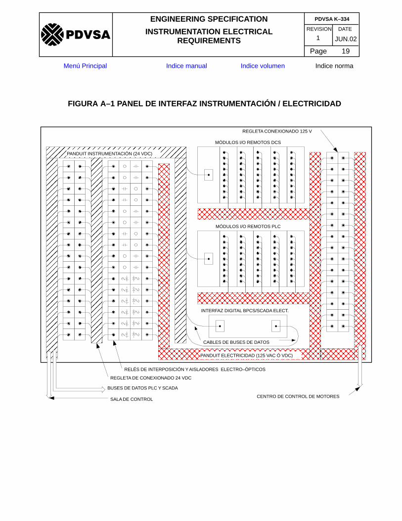
APPENDIX A (ADDITION)REQUIREMENTS FOR ELECTRICAL/INSTRUMENTATION (E/I) INTERFACE
PANEL
1. Instrumentation signals (24 VDC, wiring level 1) shall be physically separated frompower control signals (120 VAC/125 VDC, wiring level 3) by means of separateraceways (panduits) and separate termination boards. See table 2, page 18 of PIPPCCEL001, tray to tray spacing.
2. Cabinet and components shall be clearly identified, as per PDVSA K–330, ControlPanels and Consoles
3. Signals in termination boards, isolating relay boards and PLC I/O cards shall begrouped as per electrical equipment. In general, each piece of electrical equipment(e.g. motor) may have some or all of the following monitoring and control signals:
� ON command� Off command� ON/OFF status� LOCAL/REMOTE status� Electrical failure indication
4. Electrical separation of signals shall be effected by means of interposing relays orelectro–optic isolators, or by the use of dedicated remote I/O modules with highpower level I/O’s (120 VAC, 125 VDC and higher), inside the E/I interface panel.
5. The Instrument/Electrical interface panel may also be used to house the digitalinterface between the BPCS and the electrical supervisory system.
6. For a typical equipment distribution of the Electrical/Instrumentation InterfacePanel, see figure A–1.
ÓÓÓÓÓÓÓÓÓÓÓÓÓÓÓÓÓÓÓÓÓÓÓÓÓÓÓÓÓÓÓÓÓÓÓÓÓÓ
ÓÓÓÓÓÓÓÓÓÓÓÓÓÓÓÓÓÓÓÓÓÓÓÓÓÓÓÓÓÓÓÓÓÓÓÓÓÓÓÓÓÓ
ÓÓÓÓÓÓÓÓÓÓÓÓÓÓÓÓÓÓÓÓÓÓÓÓÓÓÓÓÓÓ
ÔÔÔÔÔÔÔÔÔÔÔÔÔÔÔÔÔÔÔÔÔÔÔÔÔÔÔÔÔÔÔÔÔÔÔÔÔÔÔÔÔÔÔÔÔÔÔÔÔÔÔÔÔÔÔÔÔÔÔÔÔÔÔÔÔÔÔÔÔÔ
ÓÓÓÓÓÓÓÓÓÓÓÓÓÓÓÓÓÓÓÓÓÓÓÓÓÓÓÓÓÓÓÓÓÓÓÓÓÓ
ÔÔÔÔÔÔÔÔÔÔÔÔÔÔÔÔÔÔÔÔÔÔÔÔ
ÔÔÔÔÔÔÔÔÔÔÔ
ÔÔÔÔÔÔÔÔÔÔÔ
ÔÔÔÔÔÔÔÔÔÔÔ
ÔÔÔÔÔÔÔÔÔÔÔÔÔÔÔÔÔÔÔÔÔÔÔÔÔÔÔÔÔÔÔÔÔÔÔÔ
ÔÔÔÔÔÔÔÔÔÔÔÔÔÔÔÔÔÔÔÔÔÔÔÔÔÔÔÔÔÔÔÔÔÔÔÔÔÔÔÔÔÔ
ÔÔÔÔÔÔÔÔÔÔÔÔÔÔÔÔÔÔÔÔÔÔÔÔÔÔÔÔÔÔÔÔÔÔÔÔÔÔÔÔÔÔ
PANDUIT INSTRUMENTACIÓN (24 VDC)
MÓDULOS I/O REMOTOS DCS
MÓDULOS I/O REMOTOS PLC
INTERFAZ DIGITAL BPCS/SCADA ELECT.
REGLETA CONEXIONADO 125 V
CENTRO DE CONTROL DE MOTORES
REGLETA DE CONEXIONADO 24 VDC
BUSES DE DATOS PLC Y SCADA
SALA DE CONTROL
CABLES DE BUSES DE DATOS
ÔÔÔÔÔÔÔÔÔÔÔÔÔÔÔÔÔÔÔÔÔÔÔÔÔÔÔÔÔÔÔÔÔÔÔÔÔÔÔÔÔÔÔÔÔÔÔÔÔÔÔÔÔÔÔÔÔÔÔÔÔÔÔÔÔÔ
ÔÔÔÔÔÔÔÔÔÔÔÔÔÔÔÔÔÔÔÔÔÔ
RELÉS DE INTERPOSICIÓN Y AISLADORES ELECTRO–ÓPTICOS
ÔÔÔÔÔÔÔÔÔÔÔ
ÔÔÔÔÔÔÔÔÔÔÔ
ÔÔÔÔÔÔÔÔÔÔÔ
ÔÔÔÔÔÔÔÔÔÔÔ
ÔÔÔÔÔÔÔÔÔÔÔ
ÔÔÔÔÔÔÔÔÔÔÔ
ÔÔÔÔÔÔÔÔÔÔÔ
ÔÔÔÔÔÔÔÔÔÔ
PANDUIT ELECTRICIDAD (125 VAC Ó VDC)
FIGURA A–1 PANEL DE INTERFAZ INSTRUMENTACIÓN / ELECTRICIDAD
REVISION DATE
ENGINEERING SPECIFICATION
INSTRUMENTATION ELECTRICALREQUIREMENTS
Page 19
JUN.021
PDVSA K–334
�����
Menú Principal Indice manual Indice volumen Indice norma
REVISION DATE
ENGINEERING SPECIFICATION
INSTRUMENTATION ELECTRICALREQUIREMENTS
Page 20
JUN.021
PDVSA K–334
�����
Menú Principal Indice manual Indice volumen Indice norma
APPENDIX B (ADDITION)
GUIDELINES FOR GROUNDING OF ELECTRONIC EQUIPMENTThe following guidelines may be applied in the design of instrumentationgrounding systems. The standard of reference is IEEE 1100, 1999,Recommended Practice for Powering and Grounding Electronic Equipment
1. Grounding system consists of four (4) distinct, solidly (e.g.: galvanically)interconnected functional subsystems. They are as follows:
a. NEC 250 described fault and personnel protection grounding subsystems,including the earth–grounding conductors (green wires), earth groundingelectrodes (generally in the form of a plant–wide grounding grid) and relatedgrounding electrode conductors. This subsystem is also called the powersystem ground or the AC safety ground, and is installed following theguidelines of PDVSA 90619.1.091, Puesta a Tierra yProtección contraSobre tensiones. Outside the scope of this specification.
b. Signal reference structure (SRS), consisting either of a signal referencegrounding plane (SRGP) or a signal reference grounding grid (SRGG), andinstalled following the original equipment manufacturers instructions and therecommendations made in chapter 8 of IEEE 1100, 1999. The function of theSRS is to provide an effective high frequency grounding system forprotection of electronic equipment against damage or interference causedby power system faults or lighting strikes.
c. Lightning protection subsystem, installed per PDVSA electrical guidelines.This subsystem is outside the scope of this specification.
d. Telecommunications, data transmission and signaling circuit surgeprotection grounding subsystem, as installed per the original equipmentmanufacturer’s instructions, the requirements of the NEC andrecommendations made in chapters 8 and 9 of IEEE 1100, 1999. Outsidethe scope of this specification.
2. SRS shall be installed as per IEEE, 1100, chapter 8.5.4. See below a summary listof recommended practices for installing a Signal Reference Ground Grid, extractedfrom IEEE 1100, 1999, par. 8.5.4.8
a. Follow the NEC and other related applicable codes and standards for safegrounding. There is no conflict between personal safety grounding andeffective higher–frequency grounding for electrical systems and theirassociated electronic equipment.
b. Select a suitable signal reference grid approach and assure that it isengineered, installed and maintained properly.
c. Permanently and effectively bond the signal reference grid to all accessiblebuilding steel and to each metallic path (e.g.: conduits, raceways, cable
REVISION DATE
ENGINEERING SPECIFICATION
INSTRUMENTATION ELECTRICALREQUIREMENTS
Page 21
JUN.021
PDVSA K–334
�����
Menú Principal Indice manual Indice volumen Indice norma
trays, pipes and ducts) that cross into the SRG in any plane or within 1.8 m(6 ft) of the SRG.
d. If a single point of entry for power, grounding cables and other metallic itemsinto the space exists (e.g.: physical ground window or bulkhead), thensingle–point grounding of the SRG is acceptable. The electronic loadequipment installed on the SRG may be multipoint grounded or single pointgrounded to the SRG, depending on the signal frequency of interest.
e. Bond the signal reference grid to each piece of electronic equipment and toany other electrical or mechanical equipment located on the SRG.
f. Bonding connections to the SRG should be as short as practical with nosharp folds or bends. Flexible flat straps are preferred to the use of roundconductors.
g. Where in accordance with manufacturer requirements, more than onebonding conductor for each piece of equipment should be used. Theseconductors should be connected to opposing corners of the equipment andto the nearest, but separate points on the SRG. These conductors shouldbe short (less than 0.5 m) and of different lengths (at least 20%).
h. Electronic equipment should not be installed nearest to the outer edges ofthe SRG if practicable. Instead, this equipment should be installed one ormore SRG conductor intersections (about 1 m) towards the center of theSRG . . . HVAC equipment and panelboards should be connected to any SRGconductor, or to the outermost SRG conductor. Where feasible, criticalequipment should be located and bonded to the SRG greater than 1.8 m (6ft) away from building steel or other potential lightning current or sideflashpaths.
i. All separatedly derived systems serving equipment located on the SRGshould have their power grounding point (i.e.: neutral–to–ground bond)connected to the SRG by a suitable bonding strap, This connection is inaddition to the required connection of the grounding electrode conductor tothe grounding electrode (AC safety ground).
j. All HVAC equipment, its associated piping, panelboards, switchboards,transformers and similar electrical or mechanical equipment within theprotected area should be bonded to the signal reference grid.
k. No special or supplementary grounding connections should be made toremote or dedicated earth grounding points, nor should there be any similarattempt to provide any form of separate earth ground paths to or from theSRG or any equipment installed upon it.
l. All interconnecting communications, data and power cables should lay on orvery close to the SRG.
REVISION DATE
ENGINEERING SPECIFICATION
INSTRUMENTATION ELECTRICALREQUIREMENTS
Page 22
JUN.021
PDVSA K–334
�����
Menú Principal Indice manual Indice volumen Indice norma
m. Construction documentation should be complete in all details, including theproper grounding and bonding of HVAC equipment, piping, raceways, andsimilar items, The engineer preparing the documentation should not expectinstallers to complete the design.
3. Single point dedicated instrumentation grounding (tree structure) shall beconsidered only for small installations of analog instrumentation. Instrumentationgrounding system shall be firmly bonded to the AC safety ground.
4. Separate grounding electrodes intentionally not bonded to the power systemgrounding are strictly forbidden. This is usually known as ”clean ground”, ”signalground”, ”instrument ground”. This type of installation is forbidden by NEC, sinceit may cause extreme and hazardous voltage conditions to exist between differentlygrounded metal objects during power system faults and lightning activities.Furthermore, as explained in IEEE 1100, 1999, this type of installation does noteffectively protect against EMI.
5. Signal or shield grounding bars shall be solidly bonded to cabinet frames.
6. Cable tray systems shall be part of the SRS, as per IEEE 1100, Sc. 8.4.12
7. Raceways, external metal cladding of armored cables and metal conduits shall bepart of the SRS, as per IEEE 1100, 1999, section 8.4.8.
8. Cable tray systems shall be solidly grounded at entrance to control building.
9. For connections to the SRG, short length (less than 0.5 m) flat grounding strapsshall be used.
10. Grounding straps shall be affixed to metal conduits and armored cables by meansof grounding bushings, in order to insure a low impedance bond.
11. Metallic junction boxes shall be solidly bonded to plant ground by means of flatgrounding straps.
12. Junction box sub panels (back plane) shall be solidly bonded to ground. Fornon–metallic junction boxes, a grounding strap bonded to external grounding lugshall be used.
13. UPS System shall be grounded as per IEEE1100, 1999, Sc. 8.5.2.
14. Shields for instrumentation analog, pulse and digital signals shall be grounded atcontrol room cabinet.
REVISION DATE
ENGINEERING SPECIFICATION
INSTRUMENTATION ELECTRICALREQUIREMENTS
Page 23
JUN.021
PDVSA K–334
�����
Menú Principal Indice manual Indice volumen Indice norma
APPENDIX C (ADDITION)
TABLE OF CONTENTS OF THE INTRINSICALLY SAFE DOCUMENT OF COMPLIANCE
(Note: For nonincendive installations, the guidelines below apply as noted)
As a minimum, the Intrinsically Safe (or Nonincendive) System Document ofCompliance shall be provided with the following sections:
1. Frontispiece, including a box with the history of revisions/approvals.
2. Scope, indicating the scope of the document which is, basically, the show of proofof the correct design, installation and verification of the intrinsically safe and/ornonincendive equipment and circuits designed, procured and installed within thescope of the specific project under consideration.
3. List of Applicable Standards. Including PDVSA K–334 and those listed inparagraphs 11.2 and 12.2.
4. General Statement of Compliance. In this section, the EPC contractor shalldeclare that the instrumentation electrical installation is effectively designed asan intrinsically safe and/or nonincendive system, indicating its compliancewith each and all sections of the above mentioned mandatory standards andPDVSA requirements. Where alternatives are allowed, the document shalldescribe the specific way in which compliance was obtained. Also, the intent andextent of the approved exceptions, if any, shall be described.
5. Calculations: This section shall include the Control Drawing for each distinctivetype of intrinsically safe or nonincendive circuit, as defined in Section 504–10 ofthe NEC. The Control Drawing for each type of circuit shall use the greater length(worst case), of interconnecting wire for the calculations proving that the safetyparameters are within acceptable range. A list of all instrument loops for whicheach Control Drawing applies shall be included. For nonincendive circuits, controldrawings shall be similar in form to those for intrinsic safety circuits, but calculationsshall follow general guidelines as stated in ISA S12.12.
6. Certificates of Approval for Intrinsically Safe and Associated Apparatus:This section shall present the official certificates of approval for each and everyintrinsically safe apparatus and associated apparatus installed in the plant,issued by an internationally recognized certifying authority: FM, UL, CSA,BASEEFA, PTB, CESI, etc. The apparatus shall be approved for the specifichazardous area classification where they are to be installed, according to the NFPA70 Articles 500 to 503 hazardous location classification scheme and the NFPA497M group and auto–ignition temperature (AIT) classification. Each certificateshall be accompanied with the corresponding list of instrument tags covered by thecertificate.
REVISION DATE
ENGINEERING SPECIFICATION
INSTRUMENTATION ELECTRICALREQUIREMENTS
Page 24
JUN.021
PDVSA K–334
�����
Menú Principal Indice manual Indice volumen Indice norma
7. Certificates of Approval for Nonincendive and Associated Apparatus: Thissection shall present the official certificates of approval for each and everynonincendive apparatus and associated apparatus installed in the plant,issued by an internationally recognized certifying authority: FM, UL, CSA,BASEEFA, PTB, CESI, etc. The apparatus shall be approved for the specifichazardous area classification where they are to be installed, according to the NFPA70 Articles 500 to 503 hazardous location classification scheme and the NFPA497M group and auto–ignition temperature (AIT) classification. Each certificateshall be accompanied with the corresponding list of instrument tags covered by thecertificate.
8. Cable and Wire Certifications: This section shall include the pertinent cable andwire guaranteed electrical and physical specifications from the suppliers, as wellas the results of the program of spot–wise inspections of these wires and cablesfor the pertinent physical and electrical parameters: wire and insulation materials,minimum insulation thickness, electrical insulation test results, electricalparameter test results (capacitance per unit length, inductance per unit length, R/Lratio).
9. Design and Installation Documents/Instructions: This section shall include areference list of all the specific design standards and specifications, engineeringdocuments and drawings, QA/QC specifications, purchase specifications andinstallation instructions pertinent to the attainment of a correctly designed andinstalled intrinsically safe and/or nonincendive system. The list may include, butnot be limited to:
� Specifications for grounding of intrinsically safe and nonincendive circuits� Grounding system diagrams� Shield bonding instructions� Instructions for identification of intrinsically safe cables, accessories and
components� Instructions for correct routing and separation of intrinsically safe wiring and
cable trays� Purchase specifications for cabinets and equipment using intrinsically safe or
nonincendive components� Construction inspection plans and verification forms, etc.
10. Quality Control of Fabrication. This section shall include a reference list of allequipment or system vendor inspection books where inspection/verification formstestifying to the correct design and installation of intrinsically safe circuits andcomponents are filed.
11. Quality Control of Construction. This section shall include a reference list of allinspection forms filed in the Construction Quality Control Book where correctinstallation of intrinsically safe equipment and wiring is verified.