900A/12V Battery Jump Starter Power Bank with Super-Bright ...

ESP PANELSTM
& SYSTEM COMPONENTSBrochure, Instruction and connection manual
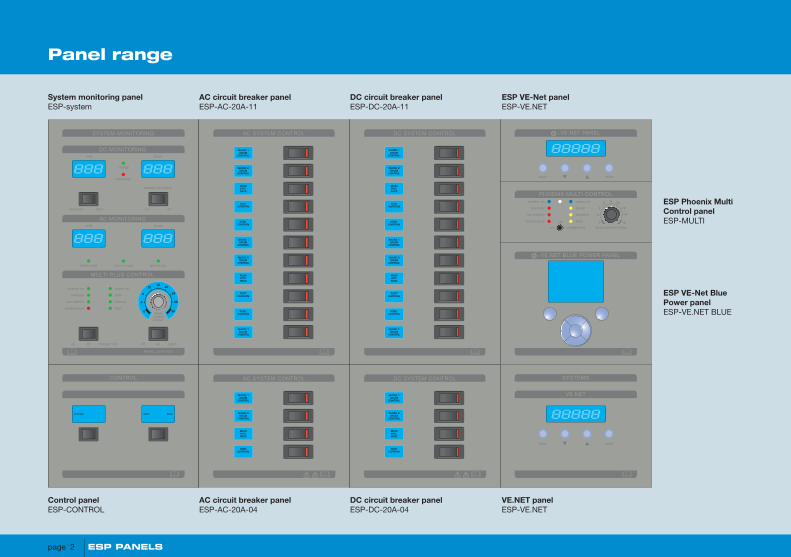
Panel range
System monitoring panelESP-system
Control panelESP-CONTROL
AC circuit breaker panelESP-AC-20A-11
AC circuit breaker panelESP-AC-20A-04
DC circuit breaker panelESP-DC-20A-11
DC circuit breaker panelESP-DC-20A-04
ESP VE-Net panelESP-VE.NET
ESP Phoenix Multi Control panelESP-MULTI
ESP VE-Net Blue Power panelESP-VE.NET BLUE
VE.NET panelESP-VE.NET
88888
SYSTEMS
VE.NET
back enter
DC MONITORINGamps
battery iso switch
volts
ampsvolts
domestic start
on
on off
AC MONITORING
MULTI PLUS CONTROL
PANEL CONTROL
mains oninverter on
bulk
absorp
float
overload
low battery
shore in use gen in use shore avail
temperature
charge
discharge
charger only
shorecurrentlimiter
off off lightson
SYSTEM MONITORING
888
888 888
888
0
4
8
1216
20
24
28
30
AC SYSTEM CONTROL
SHORE 1DRUM
CONTROL
SHORE 2DRUM
CONTROL
MAINHYD.PACK
PORTCAPSTAN
STBD.CAPSTAN
SHORE 1DRUM
CONTROL
SHORE 2DRUM
CONTROL
MAINHYD.PACK
PORTCAPSTAN
STBD.CAPSTAN
SHORE 1DRUM
CONTROL
DC SYSTEM CONTROL
SHORE 1DRUM
CONTROL
SHORE 2DRUM
CONTROL
MAINHYD.PACK
PORTCAPSTAN
STBD.CAPSTAN
SHORE 1DRUM
CONTROL
SHORE 2DRUM
CONTROL
MAINHYD.PACK
PORTCAPSTAN
STBD.CAPSTAN
SHORE 1DRUM
CONTROL
stopstartpreheat
CONTROL AC SYSTEM CONTROL
SHORE 1DRUM
CONTROL
SHORE 2DRUM
CONTROL
MAINHYD.PACK
PORTCAPSTAN
DC SYSTEM CONTROL
SHORE 1DRUM
CONTROL
SHORE 2DRUM
CONTROL
MAINHYD.PACK
PORTCAPSTAN
back enter
VE.NET PANEL
88888
PHOENIX MULTI CONTROL
0
2
4
6 8 10
12
14
16
mains oninverter on
boost
equalize
overload
low battery
temperature
on charger only
off float
shore current limiter
VE.NET BLUE POWER PANEL
page 2 ESP PANELS
D C L i n k B o x - 5 w a y
Main supply OK
Battery
connection +
Fuse 5 OK
Fuse and supply test
Fuse 4 OK
Fuse 3 OK
Fuse 2 OK
Fuse 1 OK
Battery connection reversed if lit
Battery
connection -
BMV 501/VBC
System Panel A
System Panel B
Negative returns
I- (d) shunt + load end
Battery 2 +
+ Multi voltage sense
- Multi voltage sense
Mag latch batt. isolator
Mag latch batt. isolator
I+ (c) shunt - bat end
+VS (e) voltage sense
+ (g) +VE supply
- (f) -VE supply
-VS voltage sense
LITTLEFUSE
MEGA 300A
LITTLEFUSE
MEGA 300A
LITTLEFUSE
MEGA 200A
LITTLEFUSE
MEGA 100A
09 E
E
E
E
E
E
E
E
E
E
E
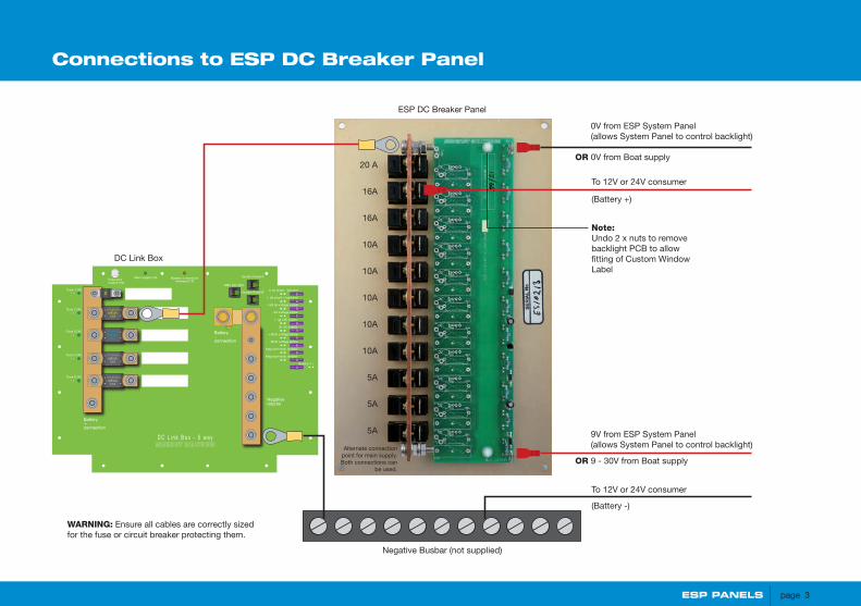
Connections to ESP DC Breaker Panel
DC Link Box
0V from ESP System Panel (allows System Panel to control backlight)
OR 0V from Boat supply
ESP DC Breaker Panel
9V from ESP System Panel (allows System Panel to control backlight)
OR 9 - 30V from Boat supply
To 12V or 24V consumer
(Battery +)
To 12V or 24V consumer
(Battery -)
Negative Busbar (not supplied)
WARNING: Ensure all cables are correctly sized for the fuse or circuit breaker protecting them.
Alternate connection point for main supply. Both connections can
be used.
20 A
16A
16A
10A
10A
10A
10A
10A
5A
5A
5A
Note:Undo 2 x nuts to remove backlight PCB to allow fitting of Custom Window Label
ESP PANELS page 3

Connections to ESP Breaker Panel - with single AC group
RCD(not supplied)
0V from ESP System Panel (allows System Panel to control backlight)
OR 0V from Boat supply
ESP AC Breaker Panel
9V from ESP System Panel (allows System Panel to control backlight)
OR 9 - 30V from Boat supply
To 230V consumer (live)
To 230V consumer (neutral)
Neutral Busbar (not supplied)
WARNING:
The installer must ensure that the rear of the panel and live bus bar is inaccessible once installed.
Ensure all cables are correctly sized for the fuse or circuit breaker protecting them.
Alternate connection point for main supply. Both connections can
be used.
20 A
16A
16A
10A
10A
10A
10A
10A
5A
5A
5A
Note:Undo 2 x nuts to remove backlight PCB to allow fitting of Custom Window Label
Earth Busbar (not supplied)All supply & consumer earths to this point
To 230V consumer (earth)
page 4 ESP PANELS

Connections to ESP AC Breaker Panel - with two AC groups
0V from ESP System Panel (allows System Panel to control backlight)
OR 0V from Boat supply
ESP AC Breaker Panel
9V from ESP System Panel (allows System Panel to control backlight)
OR 9 - 30V from Boat supply
To high load 230V consumer (live)
To high load 230V consumer (neutral)
Inverter group Neutral Busbar(not supplied)
20 A
16A
16A
10A
10A
10A
10A
10A
5A
5A
5A
WARNING:
The installer must ensure that the rear of the panel and live bus bar is inaccessible once installed.
Ensure all cables are correctly sized for the fuse or circuit breaker protecting them.
Inverter groupRCD(not supplied)
High load group RCD
(not supplied)
High load group Neutral Busbar (not supplied)
To inverter load 230V consumer (live)
To inverter load 230V consumer (neutral)
WARNING:Cut busbar to separate
high load and inverter
load groups. A gap of at
least 5mm is required.
Note:Undo 2 x nuts to remove backlight PCB to allow fitting of Custom Window Label
To 230V consumers (earth)Earth Busbar (not supplied)All supply & consumer earths to this point
ESP PANELS page 5

Control Panel
0V from ESP System Panel (allows System Panel to control backlight)
OR 0V from Boat supply
9V from ESP System Panel (allows System Panel to control backlight)
OR 9 - 30V from Boat supply
Note:A connection PCB is supplied
loose. This allows alternate switch actions to be fitted prior
to the connection PCB being soldered onto the switch. Your distributor can fit the PCB and
switch at time of ordering.
Switch capacity is 4 Amps max.
Switch supplied is centre off momentary either way.
Alternative switch actions can be purchased separately
Note:Undo 4 x nuts to remove backlight PCB to allow fitting of Custom Window Label
page 6 ESP PANELS

D C L i n k B o x - 5 w a y
Main supply OK
Battery
connection +
Fuse 5 OK
Fuse and supply test
Fuse 4 OK
Fuse 3 OK
Fuse 2 OK
Fuse 1 OK
Battery connection reversed if lit
Battery
connection -
BMV 501/VBC
System Panel A
System Panel B
Negative returns
I- (d) shunt + load end
Battery 2 +
+ Multi voltage sense
- Multi voltage sense
Mag latch batt. isolator
Mag latch batt. isolator
I+ (c) shunt - bat end
+VS (e) voltage sense
+ (g) +VE supply
- (f) -VE supply
-VS voltage sense
LITTLEFUSE
MEGA 300A
LITTLEFUSE
MEGA 300A
LITTLEFUSE
MEGA 200A
LITTLEFUSE
MEGA 100A
09 E
E
E
E
E
E
E
E
E
E
E
Connections to ESP System Control Panel using Mark 2 DC Link Box
ESP PowerMan
DC Link Box
9V+ for ESP DC & AC Breaker Panel backlight
0V- for ESP DC & AC Breaker Panel backlight
RJ12 RJ12
RJ45
Multicompact 12/1200/50
phoenix
RJ45
ESP System Control Panel
ESP PANELS page 7

System Accessories Labelling
Custom window labels
The Breaker and Control Panels are designed to accept custom legends, to suit your needs.
Easy to use MS Word templates for these are available for download at:www.victronenergy.com
Simply fill these in, print on Laser Film and cut to size. To install the label, remove the backlight PCB by undoing the securing nuts. Lay the label onto the rear of the window and reassemble.
ESP PowerMan32A
Designed for systems with up to 8Kw generator and one or two MultiPlus units.
ESP PowerMan 64A
Designed for systems with up to 16Kw generator and two to four MultiPlus units
ESP PowerMan 20A
Designed for systems with up to 5Kw generator and one MultiPlus unit.
ESP PowerManThe system panel acquires its AC voltage and current from the ESP PowerMan Unit. These provide automatic switching between shore power, generator and MultiPlus. In addition, high load circuits are disconnected when only Inverter power is available.
The system panel acquires its DC voltage and current from the DC Link Box.
The Link Box provides primary protection for heavy DC consumers and avoids “spaghetti junction” wiring at the battery terminal.
DC Link Box
page 8 ESP PANELS

DC Link Box
D C L i n k B o x - 5 w a y
Main supply OK
Battery
connection+
Fuse 5 OK
Fuse andsupply test
Fuse 4 OK
Fuse 3 OK
Fuse 2 OK
Fuse 1 OK
Battery connectionreversed if lit
Battery
connection-
Negativereturns
I- (d) shunt + load end
Battery 2 +
+ Multi voltage sense
- Multi voltage sense
Mag latch batt. isolator
Mag latch batt. isolator
I+ (c) shunt - bat end
+VS (e) voltage sense
+ (g) +VE supply
- (f) -VE supply
-VS voltage sense
A
C
BShunt
This is not a VE.Net connector
LITTLEFUSE
MEGA300A
LITTLEFUSE
MEGA300A
LITTLEFUSE
MEGA200A
LITTLEFUSE
MEGA100A
09
E
E
E
E
E
E
E
E
E
E
E
Alternator
Cyrix batteryseparator
Mag latchbatteryisolator
Service BatteryStarter Battery
StarterMotor
DC MONITORINGamps
battery iso switch
volts
ampsvolts
domestic start
on
on off
AC MONITORING
MULTI PLUS CONTROL
PANEL CONTROL
mains oninverter on
bulk
absorp
float
overload
low battery
shore in use gen in use shore avail
temperature
charge
discharge
charger only
shorecurrentlimiter
off off lightson
SYSTEM MONITORING
888
888 888
888
0
4
8
1216
20
24
28
30
DC SYSTEM CONTROL
SHORE 1DRUM
CONTROL
SHORE 2DRUM
CONTROL
MAINHYD.PACK
PORTCAPSTAN
STBD.CAPSTAN
SHORE 1DRUM
CONTROL
SHORE 2DRUM
CONTROL
MAINHYD.PACK
PORTCAPSTAN
STBD.CAPSTAN
SHORE 1DRUM
CONTROL
Multicompact 12/1200/50
phoenix
Voltage Senseconnections
BMV-600Battery Monitor
A
C
D B
A ESP System Panel (available separately)
B BMV-600 connection to DC Link Box via RJ12 cable
C Voltage sense cable for starter battery. Only required if using System Panel.
D Mag latch contactor for battery isolation (available separately). Operated by control on System Panel Only required if using System Panel.
ESP PANELS page 9
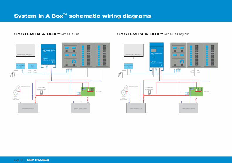
SYSTEM IN A BOX™ with MultiPlus SYSTEM IN A BOX™ with Multi EasyPlus
System In A BoxTM schematic wiring diagrams
DC Link Box
Alternator (option) Cyrix battery
separator (option)
Service Battery (option) Starter Battery (option)
Starter Motor
(not included)
DC MONITORING
AC MONITORING
MULTI PLUS CONTROL
SYSTEM MONITORING
888
888 888
888
AC SYSTEM CONTROL DC SYSTEM CONTROL
High Loads
Low Loads
EasyaPlus 12/1600/70
phoenix
Generator Max 3.6Kw (option)
ESP PowerMan - 20A
DC Link Box
Alternator (option) Cyrix battery
separator (option)
Service Battery (option) Starter Battery (option)
Starter Motor
(not included)
DC MONITORING
AC MONITORING
MULTI PLUS CONTROL
SYSTEM MONITORING
888
888 888
888
AC SYSTEM CONTROL DC SYSTEM CONTROL
High Loads
Low Loads
Multicompact 12/1200/50
phoenix
Generator Max 5Kw (option)
ESP PowerMan - 20A
RCD BOX
page 10 ESP PANELS
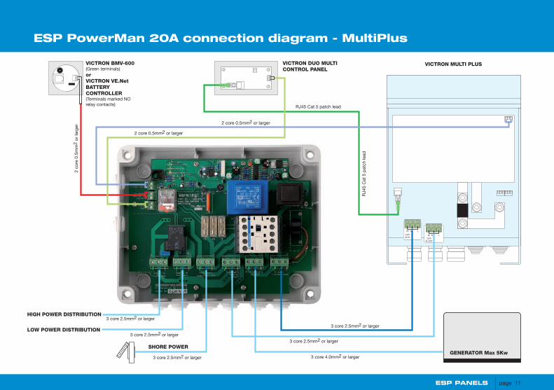
VICTRON MULTI PLUS
PE
230V AC IN
N L
PE
230V AC OUT
N L
LOW POWER DISTRIBUTION
HIGH POWER DISTRIBUTION
SHORE POWER
VICTRON BMV-600(Green terminals)orVICTRON VE.NetBATTERYCONTROLLER(Terminals marked NOrelay contacts)
2 co
re 0
.5m
m2
or la
rger
2 core 0.5mm2 or larger
2 core 0.5mm2 or larger
3 core 2.5mm2 or larger
3 core 2.5mm2 or larger
3 core 2.5mm2 or larger
3 core 2.5mm2 or larger
3 core 4.0mm2 or larger
3 core 2.5mm2 or larger
RJ45 Cat 5 patch lead
RJ4
5 C
at 5
pat
ch le
ad
VICTRON DUO MULTICONTROL PANEL
GENERATOR Max 5Kw
ESP PowerMan 20A connection diagram - MultiPlus
ESP PANELS page 11
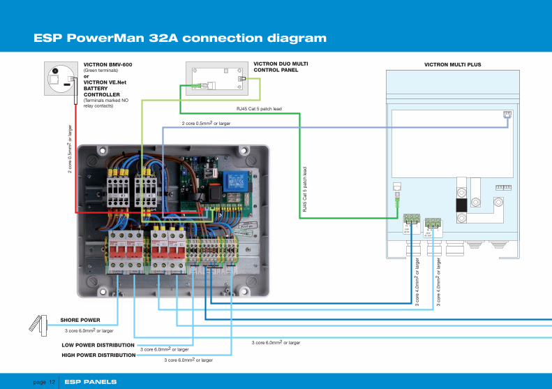
ESP PowerMan 32A connection diagram
PE
230VAC IN
N L
PE
230VAC OUT
N L
OPTIONAL SECOND - VICTRON MULTI PLUS
PE
230VAC IN
N L
PE
230VAC OUT
N L
HIGH POWER DISTRIBUTION
LOW POWER DISTRIBUTION
VICTRON MULTI PLUS
SHORE POWER
VICTRON BMV-600(Green terminals)orVICTRON VE.NetBATTERYCONTROLLER(Terminals marked NOrelay contacts)
2 co
re 0
.5m
m2
or la
rger
2 core 0.5mm2 or larger
3 core 6.0mm2 or larger
3 core 6.0mm2 or larger
3 core 6.0mm2 or larger
3 core 6.0mm2 or larger
3 co
re 4
.0m
m2
or la
rger
3 co
re 4
.0m
m2
or la
rger
3 co
re 4
.0m
m2
or la
rger
3 co
re 4
.0m
m2
or la
rger
RJ45 Cat 5 patch lead
RJ4
5 C
at 5
pat
ch le
ad
GENERATOR Max 8Kw
VICTRON DUO MULTICONTROL PANEL
page 12 ESP PANELS

PE
230VAC IN
N L
PE
230VAC OUT
N L
OPTIONAL SECOND - VICTRON MULTI PLUS
PE
230VAC IN
N L
PE
230VAC OUT
N L
HIGH POWER DISTRIBUTION
LOW POWER DISTRIBUTION
VICTRON MULTI PLUS
SHORE POWER
VICTRON BMV-600(Green terminals)orVICTRON VE.NetBATTERYCONTROLLER(Terminals marked NOrelay contacts)
2 co
re 0
.5m
m2
or la
rger
2 core 0.5mm2 or larger
3 core 6.0mm2 or larger
3 core 6.0mm2 or larger
3 core 6.0mm2 or larger
3 core 6.0mm2 or larger
3 co
re 4
.0m
m2
or la
rger
3 co
re 4
.0m
m2
or la
rger
3 co
re 4
.0m
m2
or la
rger
3 co
re 4
.0m
m2
or la
rger
RJ45 Cat 5 patch lead
RJ4
5 C
at 5
pat
ch le
ad
GENERATOR Max 8Kw
VICTRON DUO MULTICONTROL PANEL
Termination detail
ESP PANELS page 13
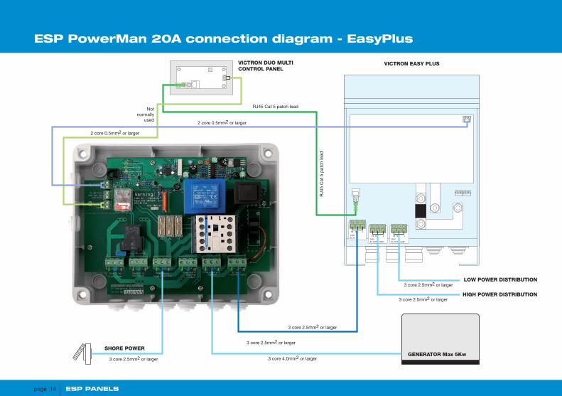
ESP PowerMan 20A connection diagram - EasyPlus
VICTRON EASY PLUS
PE
230V AC IN
N L
PE
230V AC OUT HIGH
N L PE
230V AC OUT LOW
N L
LOW POWER DISTRIBUTION
HIGH POWER DISTRIBUTION
SHORE POWER
2 core 0.5mm2 or larger
2 core 0.5mm2 or larger
3 core 2.5mm2 or larger
3 core 2.5mm2 or larger
3 core 2.5mm2 or larger
3 core 2.5mm2 or larger
3 core 4.0mm2 or larger
3 core 2.5mm2 or larger
RJ45 Cat 5 patch lead Notnormally
used
RJ4
5 C
at 5
pat
ch le
ad
GENERATOR Max 5Kw
VICTRON DUO MULTICONTROL PANEL
page 14 ESP PANELS
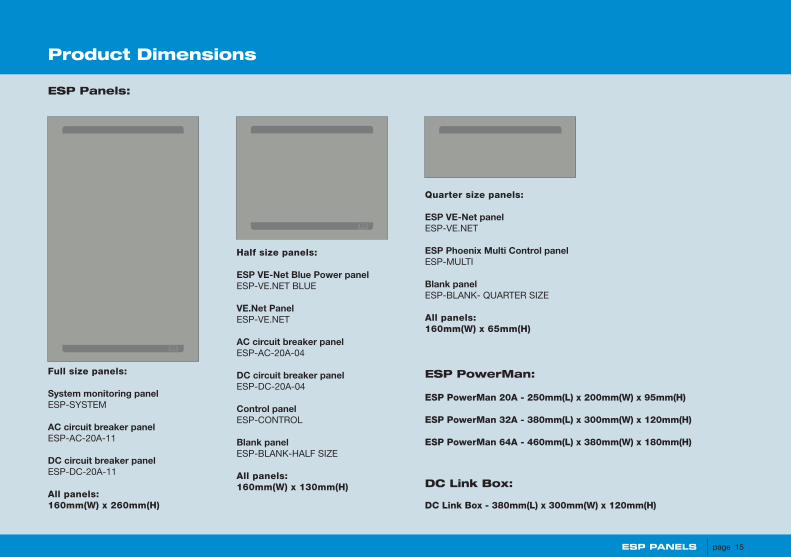
Full size panels:
System monitoring panelESP-SYSTEM
AC circuit breaker panelESP-AC-20A-11
DC circuit breaker panelESP-DC-20A-11
All panels:160mm(W) x 260mm(H)
Half size panels:
ESP VE-Net Blue Power panelESP-VE.NET BLUE
VE.Net PanelESP-VE.NET
AC circuit breaker panelESP-AC-20A-04
DC circuit breaker panelESP-DC-20A-04
Control panelESP-CONTROL
Blank panelESP-BLANK-HALF SIZE
All panels:160mm(W) x 130mm(H)
Quarter size panels:
ESP VE-Net panelESP-VE.NET
ESP Phoenix Multi Control panelESP-MULTI
Blank panelESP-BLANK- QUARTER SIZE
All panels:160mm(W) x 65mm(H)
ESP Panels:
ESP PowerMan 20A - 250mm(L) x 200mm(W) x 95mm(H)
ESP PowerMan 32A - 380mm(L) x 300mm(W) x 120mm(H)
ESP PowerMan 64A - 460mm(L) x 380mm(W) x 180mm(H)
ESP PowerMan:
DC Link Box - 380mm(L) x 300mm(W) x 120mm(H)
DC Link Box:
Product Dimensions
ESP PANELS page 15

ESP PANELSTM
Distributed by:
Victron Energy B.V.De Paal 35, 1351 JG Almere-HavenP.O. Box 50016, 1305 AA Almere-HavenThe Netherlands
Tel. +31 (0)36 535 97 00Fax +31 (0)36 531 16 66 (general + service)Fax +31 (0)36 535 97 40 (sales)
E-mail [email protected]
SAL064110020 - (11/07)