
ESP JIB REEFING & FURLING Unit 0, 1 · ESP JIB REEFING & FURLING Unit 0, 1 Installation Manual –...
36
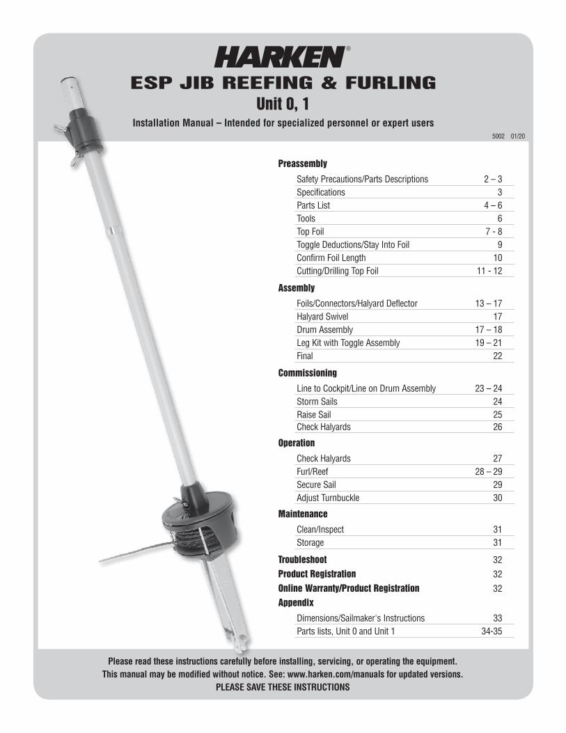
Please read these instructions carefully before installing, servicing, or operating the equipment. This manual may be modified without notice. See: www.harken.com/manuals for updated versions. PLEASE SAVE THESE INSTRUCTIONS ESP JIB REEFING & FURLING Unit 0, 1 Installation Manual – Intended for specialized personnel or expert users 5002 01/20 Preassembly Safety Precautions/Parts Descriptions 2 – 3 Specifications 3 Parts List 4 – 6 Tools 6 Top Foil 7 - 8 Toggle Deductions/Stay Into Foil 9 Confirm Foil Length 10 Cutting/Drilling Top Foil 11 - 12 Assembly Foils/Connectors/Halyard Deflector 13 – 17 Halyard Swivel 17 Drum Assembly 17 – 18 Leg Kit with Toggle Assembly 19 – 21 Final 22 Commissioning Line to Cockpit/Line on Drum Assembly 23 – 24 Storm Sails 24 Raise Sail 25 Check Halyards 26 Operation Check Halyards 27 Furl/Reef 28 – 29 Secure Sail 29 Adjust Turnbuckle 30 Maintenance Clean/Inspect 31 Storage 31 Troubleshoot 32 Product Registration 32 Online Warranty/Product Registration 32 Appendix Dimensions/Sailmaker's Instructions 33 Parts lists, Unit 0 and Unit 1 34-35
Transcript of ESP JIB REEFING & FURLING Unit 0, 1 · ESP JIB REEFING & FURLING Unit 0, 1 Installation Manual –...
Please read these instructions carefully before installing, servicing, or operating the equipment. This manual may be modified without notice. See: www.harken.com/manuals for updated versions.
PLEASE SAVE THESE INSTRUCTIONS
ESP JIB REEFING & FURLINGUnit 0, 1
Installation Manual – Intended for specialized personnel or expert users5002 01/20
Preassembly
Safety Precautions/Parts Descriptions 2 – 3 Specifications 3 Parts List 4 – 6 Tools 6 Top Foil 7 - 8 Toggle Deductions/Stay Into Foil 9 Confirm Foil Length 10 Cutting/Drilling Top Foil 11 - 12
Assembly
Foils/Connectors/Halyard Deflector 13 – 17 Halyard Swivel 17 Drum Assembly 17 – 18 Leg Kit with Toggle Assembly 19 – 21 Final 22
Commissioning
Line to Cockpit/Line on Drum Assembly 23 – 24 Storm Sails 24 Raise Sail 25 Check Halyards 26
Operation
Check Halyards 27 Furl/Reef 28 – 29 Secure Sail 29 Adjust Turnbuckle 30
Maintenance
Clean/Inspect 31 Storage 31
Troubleshoot 32
Product Registration 32
Online Warranty/Product Registration 32
Appendix
Dimensions/Sailmaker's Instructions 33 Parts lists, Unit 0 and Unit 1 34-35
2 ESP Unit 0, 1
2
1
3 4
5
7
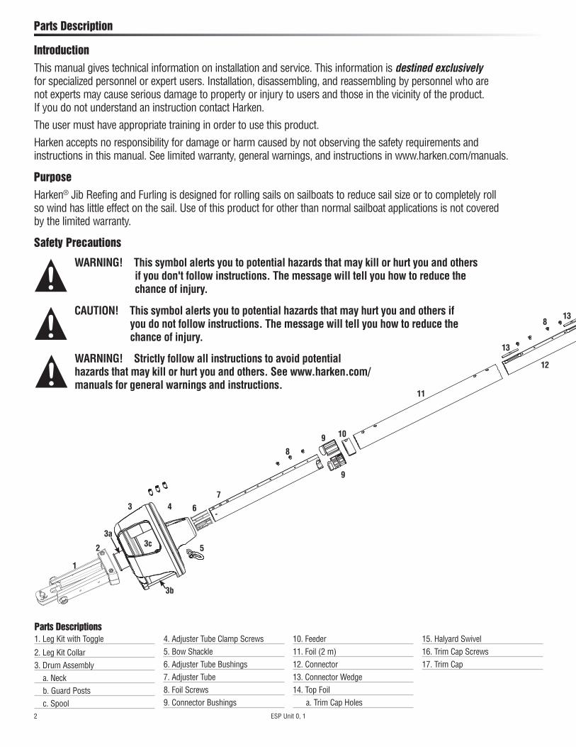
1. Leg Kit with Toggle
2. Leg Kit Collar3. Drum Assembly
a. Neckb. Guard Postsc. Spool
4. Adjuster Tube Clamp Screws5. Bow Shackle6. Adjuster Tube Bushings7. Adjuster Tube8. Foil Screws9. Connector Bushings
10. Feeder11. Foil (2 m)12. Connector13. Connector Wedge14. Top Foil
a. Trim Cap Holes
15. Halyard Swivel16. Trim Cap Screws17. Trim Cap
Parts Descriptions
Parts Description
8
9
11
10
12
3a
3b
9
8
3c
13
13
WARNING! Strictly follow all instructions to avoid potential hazards that may kill or hurt you and others. See www.harken.com/manuals for general warnings and instructions.
WARNING! This symbol alerts you to potential hazards that may kill or hurt you and others if you don't follow instructions. The message will tell you how to reduce the chance of injury.
IntroductionThis manual gives technical information on installation and service. This information is destined exclusively for specialized personnel or expert users. Installation, disassembling, and reassembling by personnel who are not experts may cause serious damage to property or injury to users and those in the vicinity of the product. If you do not understand an instruction contact Harken.
The user must have appropriate training in order to use this product.
Harken accepts no responsibility for damage or harm caused by not observing the safety requirements and instructions in this manual. See limited warranty, general warnings, and instructions in www.harken.com/manuals.
PurposeHarken® Jib Reefing and Furling is designed for rolling sails on sailboats to reduce sail size or to completely roll so wind has little effect on the sail. Use of this product for other than normal sailboat applications is not covered by the limited warranty.
Safety Precautions
CAUTION! This symbol alerts you to potential hazards that may hurt you and others if you do not follow instructions. The message will tell you how to reduce the chance of injury.
6
9
9
ESP Unit 0, 1 3
14
15
17
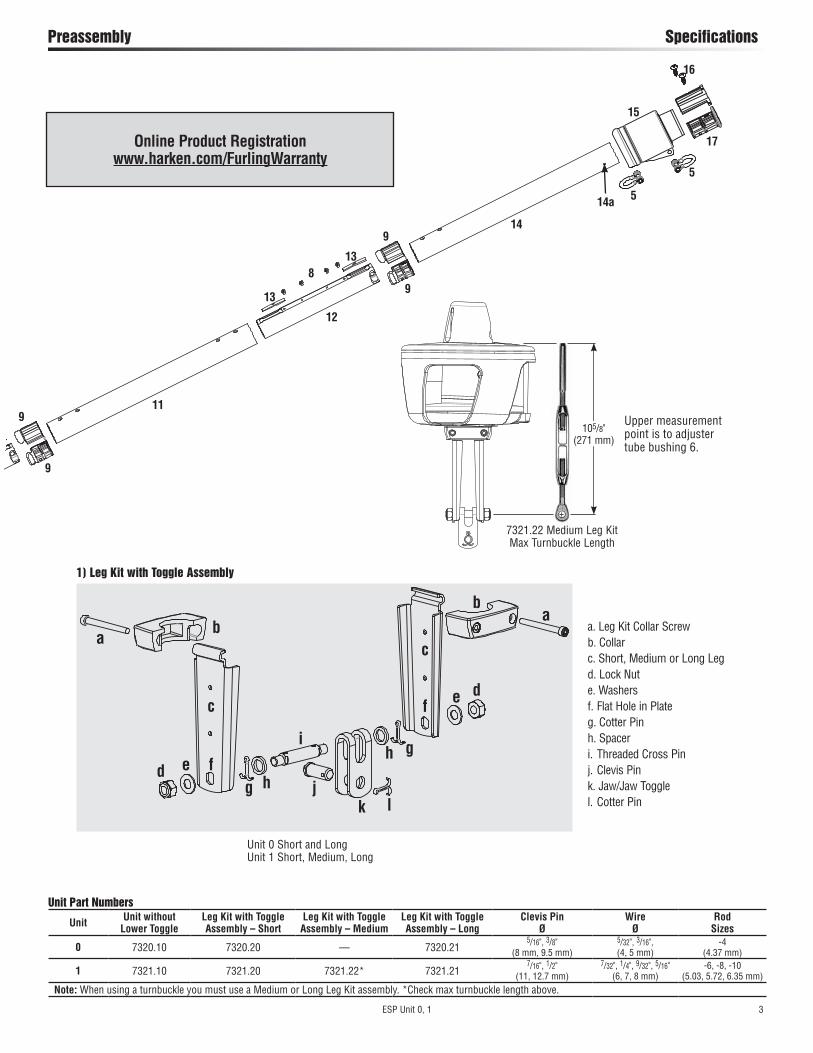
Preassembly Specifications
11
8
9
12
16
5
14a
a. Leg Kit Collar Screwb. Collarc. Short, Medium or Long Legd. Lock Nut e. Washersf. Flat Hole in Plate g. Cotter Pinh. Spaceri. Threaded Cross Pinj. Clevis Pink. Jaw/Jaw Togglel. Cotter Pin
1) Leg Kit with Toggle Assembly
aa
b
b
c
c
de
d eg h
gf
f
ih
13
13
9
5
jk l
Unit Part Numbers
Unit Unit without Lower Toggle
Leg Kit with Toggle Assembly – Short
Leg Kit with Toggle Assembly – Medium
Leg Kit with Toggle Assembly – Long
Clevis Pin Ø
Wire Ø
Rod Sizes
0 7320.10 7320.20 — 7320.215/16", 3/8"
(8 mm, 9.5 mm)5/32", 3/16", (4, 5 mm)
-4 (4.37 mm)
1 7321.10 7321.20 7321.22* 7321.217/16", 1/2"
(11, 12.7 mm)7/32", 1/4", 9/32", 5/16"
(6, 7, 8 mm)-6, -8, -10
(5.03, 5.72, 6.35 mm)Note: When using a turnbuckle you must use a Medium or Long Leg Kit assembly. *Check max turnbuckle length above.
Online Product Registration www.harken.com/FurlingWarranty
Unit 0 Short and LongUnit 1 Short, Medium, Long
105/8" (271 mm)
7321.22 Medium Leg Kit Max Turnbuckle Length
Upper measurement point is to adjuster tube bushing 6.

4 ESP Unit 0, 1
Parts List Drum Box
Bow Shackles
Halyard Swivel
DescriptionUnit 0 Unit 1
Part No. Size Length (L) Qty Part No. Size Length (L) QtyHalyard swivel H-58632 — — 1 H-55720 — — 1Drum assembly 7320.10BASE — — 1 7321.10BASE — — 1Bow shackles 2110 6 mm — 3 2110 6 mm — 3Short leg kit with toggle 7320.20 5/16", 3/8" 21/16" (52 mm) 1 7321.20 7/16", 1/2" 21/8" (53 mm) 1Medium leg kit with toggle — — — 1 7321.22 7/16", 1/2" 61/4" (159 mm) 1Long leg kit with toggle 7320.21 5/16", 3/8" 73/16" (183 mm) 1 7321.21 7/16", 1/2" 111/16" (280 mm) 1Adjuster tube clamp screws HFS1252 8 mm — 2 HFS1252 8 mm — 3Blue Loctite® 833 — — 1 833 — 1
Drum Box
Blue Loctite®
Drum Assembly
Adjuster Tube Clamp Screws
Medium or Long Leg Kit Required for installation with turnbuckle
Short Leg Kit DO NOT USE with turnbuckle
Short Medium Long
Leg Kit Relative Sizes
L
L
ESP Unit 0, 1 5
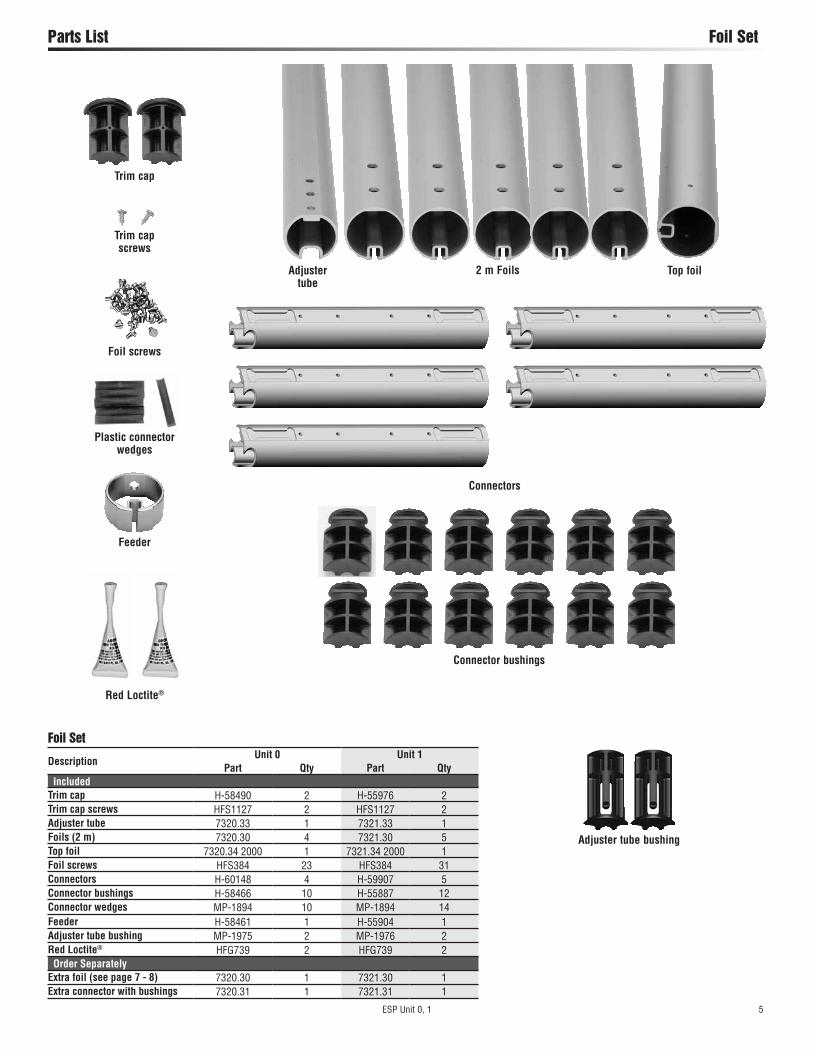
Parts List Foil Set
Adjuster tube
2 m Foils
Connector bushings
Top foil
Connectors
Foil Set
DescriptionUnit 0 Unit 1
Part Qty Part Qty IncludedTrim cap H-58490 2 H-55976 2Trim cap screws HFS1127 2 HFS1127 2Adjuster tube 7320.33 1 7321.33 1Foils (2 m) 7320.30 4 7321.30 5Top foil 7320.34 2000 1 7321.34 2000 1Foil screws HFS384 23 HFS384 31Connectors H-60148 4 H-59907 5Connector bushings H-58466 10 H-55887 12Connector wedges MP-1894 10 MP-1894 14Feeder H-58461 1 H-55904 1Adjuster tube bushing MP-1975 2 MP-1976 2Red Loctite® HFG739 2 HFG739 2 Order SeparatelyExtra foil (see page 7 - 8) 7320.30 1 7321.30 1Extra connector with bushings 7320.31 1 7321.31 1
Adjuster tube bushing
Foil screws
Trim cap screws
Trim cap
Feeder
Red Loctite®
Plastic connector wedges

6 ESP Unit 0, 1
Parts List Parts Sold Separately/Tools
Furling LineUnit Part No. Line Ø Length (ft)
0 HFG594 7 mm 551 HFG233 7 mm 70
7404 Lead Block Kit Includes 3 x 7403; 1 x 7401;
1 x 7402; 1 Horn Cleat
Halyard DeflectorUnit Part No.
0 73011 7302
Optional Parts
Rod Rigging: Harken Rod Adapter Stud Required
Rod SizeThread
Size UNF Part No.
-4 4.37 mm 7/16" 7420 -4 -6 5.03 mm 7/16" 7421 -6 -8 5.72 mm 1/2" 7422 -8 -10 6.35 mm 1/2" 7423 -10
Short Leg Kit with Toggle Do not use with turnbuckle
Medium Leg Kit with Toggle Required for turnbuckle
Long Leg Kit with Toggle Required for turnbuckle
Unit Part No.Clevis
Pin Part No.Clevis
Pin Part No.Clevis
Pin0 7320.20 5/16, 3/8 — — 7320.21 5/16, 3/8
1 7321.20 7/16, 1/2 7321.22 7/16, 1/2 7321.21 7/16, 1/2
Required Parts
Required parts sold separately by Harken:• Extra foil and connector if required. See pages 7 - 8. • Harken Short Leg Kit with toggle. Do not use with turnbuckle. • Harken Medium or Long Leg Kit with toggle. Required for turnbuckle. • Rod rigging requires Harken rod adapter stud. • Furling line. To purchase elsewhere, figure length required: Boat length + foot length of largest sail + 6' (1.8 m). Optional parts, sold separately by Harken:• Halyard Deflector. Use when halyard exits very close to stay attachment point. • 7404 Lead Block Kit and one additional 7403 if necessary. Fits 1" (25 mm) stanchions.
WARNING! Wire that is old or damaged may break sud-denly, causing an accident. Headstay condition should be checked by a professional rigger before reusing.
Preassembly Tools Required
2
17
15
1
9
8
76
4
16
5
10
12
3. Long tape measure 11. Phillips screwdriver
4. Short tape measure 12. Slotted screwdriver
5. Drill bit – 1/8" (3 mm) 13. Needle-nose pliers
6. Power drill 14. Locking Pliers
7. Hacksaw 15. Center punch
8. Side cutters 16. Hammer
9. Rat-tail file 17. Electric Tape (Use to Mark Foil)
10. Straight edge 18. Vise ( Tape Jaws to Protect Foil)
3
11
13
1. Hex keys
Unit Size
0, 1 5 mm, 6 mm
2. Socket or open end wrench
Unit Size
0 10 mm
1 16 mm
12
14
18
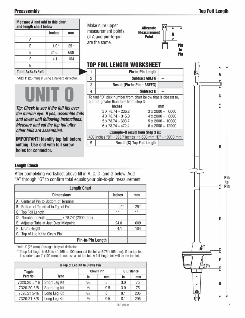
ESP Unit 0 7
Preassembly Top Foil Length
Length Chart
Dimensions Inches mm
A Center of Pin to Bottom of TerminalB Bottom of Terminal to Top of Foil 1.0* 25*C Top Foil Length ** **D Number of Foils ________ x 78.74" (2000 mm)E Adjuster Tube at Just Over Midpoint 24.0 609F Drum Height 4.1 104G Top of Leg Kit to Clevis Pin
Pin-to-Pin Length*Add 1" (25 mm) if using a halyard deflector.**If top foil length is 6.5" to 4" (165 to 100 mm) cut the foil at 6.75" (165 mm). If the top foil is shorter than 4" (100 mm) do not use a cut top foil. A full length foil will be the top foil.
Measure A and add to this chart and length chart below
Inches mm
A
B 1.0* 25*
E 24.0 609
F 4.1 104
G
Total A+B+E+F+G
*Add 1" (25 mm) if using a halyard deflector.
Make sure upper measurement points of A and pin-to-pin are the same.
1 Pin-to-Pin Length
2 Subtract ABEFG –
3 Result (Pin-to-Pin – ABEFG)
4 Subtract D –To find “D” pick number from chart below that is closest to, but not greater than total from step 3.
Inches mm3 X 78.74 = 236.2 4 X 78.74 = 315.0 5 x 78.74 = 393.7 6 x 78.74 = 472.4
3 x 2000 = 6000 4 x 2000 = 8000 5 x 2000 = 10000 6 x 2000 = 12000
Example–If result from Step 3 is:400 inches “D” = 393.7 inches 11,500 mm “D” = 10000 mm5 Result (C) Top Foil Length
After completing worksheet above fill in A, C, D, and G below. Add “A” through “G” to confirm total equals your pin-to-pin measurement.
Length Check
Alternate Measurement
PointA
TOP FOIL LENGTH WORKSHEETA
C
D
E
F
Pin to
Pin
B
G
Pin to
Pin
UNIT 0Tip: Check to see if the foil fits over the marine eye. If yes, assemble foils and lower unit following instructions. Measure and cut the top foil after other foils are assembled.
IMPORTANT! Identify top foil before cutting. Use end with foil screw holes for connector.
G Top of Leg Kit to Clevis Pin
Toggle Part No.
Type
Clevis Pin G Distance
in mm in mm
7320.20 5/16 Short Leg Kit 5/16 8 3.0 757320.20 3/8 Short Leg Kit 3/8 9.5 3.0 757320.21 5/16 Long Leg Kit 5/16 8 8.1 2067320.21 3/8 Long Leg Kit 3/8 9.5 8.1 206
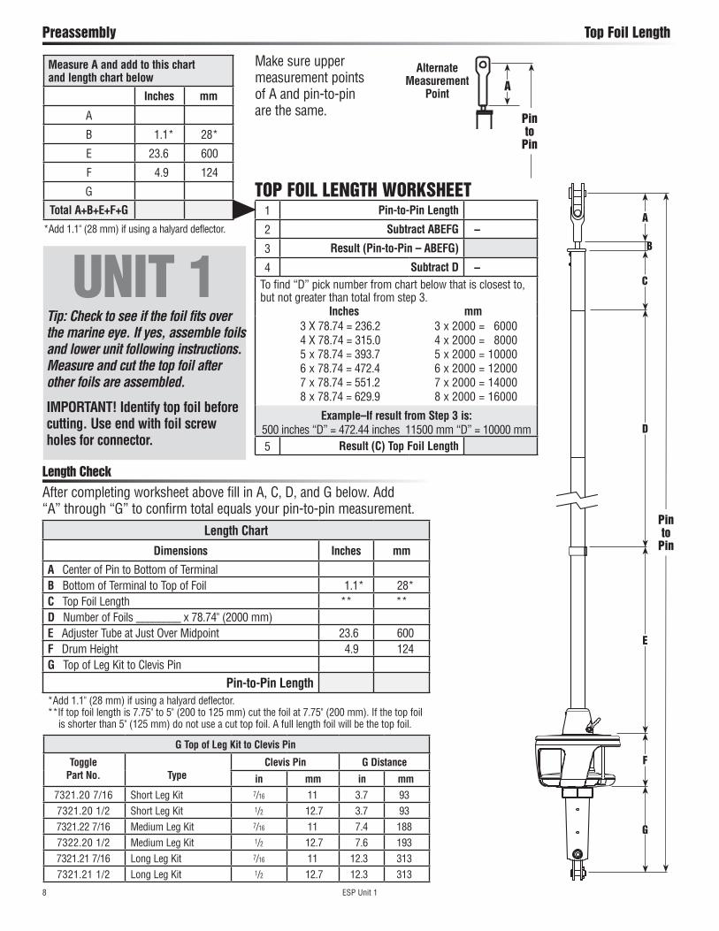
8 ESP Unit 1
Preassembly Top Foil Length
Length Chart
Dimensions Inches mm
A Center of Pin to Bottom of TerminalB Bottom of Terminal to Top of Foil 1.1* 28*C Top Foil Length ** **D Number of Foils ________ x 78.74" (2000 mm)E Adjuster Tube at Just Over Midpoint 23.6 600F Drum Height 4.9 124G Top of Leg Kit to Clevis Pin
Pin-to-Pin Length*Add 1.1" (28 mm) if using a halyard deflector.**If top foil length is 7.75" to 5" (200 to 125 mm) cut the foil at 7.75" (200 mm). If the top foil is shorter than 5" (125 mm) do not use a cut top foil. A full length foil will be the top foil.
Measure A and add to this chart and length chart below
Inches mm
A
B 1.1* 28*
E 23.6 600
F 4.9 124
G
Total A+B+E+F+G
*Add 1.1" (28 mm) if using a halyard deflector.
Make sure upper measurement points of A and pin-to-pin are the same.
1 Pin-to-Pin Length
2 Subtract ABEFG –
3 Result (Pin-to-Pin – ABEFG)
4 Subtract D –To find “D” pick number from chart below that is closest to, but not greater than total from step 3.
Inches mm3 X 78.74 = 236.2 4 X 78.74 = 315.0 5 x 78.74 = 393.7 6 x 78.74 = 472.4 7 x 78.74 = 551.2 8 x 78.74 = 629.9
3 x 2000 = 6000 4 x 2000 = 8000 5 x 2000 = 10000 6 x 2000 = 12000 7 x 2000 = 14000 8 x 2000 = 16000
Example–If result from Step 3 is:500 inches “D” = 472.44 inches 11500 mm “D” = 10000 mm5 Result (C) Top Foil Length
After completing worksheet above fill in A, C, D, and G below. Add “A” through “G” to confirm total equals your pin-to-pin measurement.
Length Check
Alternate Measurement
PointA
TOP FOIL LENGTH WORKSHEET
Pin to
Pin
G Top of Leg Kit to Clevis Pin
Toggle Part No.
Type
Clevis Pin G Distance
in mm in mm
7321.20 7/16 Short Leg Kit 7/16 11 3.7 937321.20 1/2 Short Leg Kit 1/2 12.7 3.7 937321.22 7/16 Medium Leg Kit 7/16 11 7.4 1887322.20 1/2 Medium Leg Kit 1/2 12.7 7.6 1937321.21 7/16 Long Leg Kit 7/16 11 12.3 3137321.21 1/2 Long Leg Kit 1/2 12.7 12.3 313
UNIT 1Tip: Check to see if the foil fits over the marine eye. If yes, assemble foils and lower unit following instructions. Measure and cut the top foil after other foils are assembled.
IMPORTANT! Identify top foil before cutting. Use end with foil screw holes for connector.
A
C
D
E
F
Pin to
Pin
B
G
ESP Unit 0, 1 9
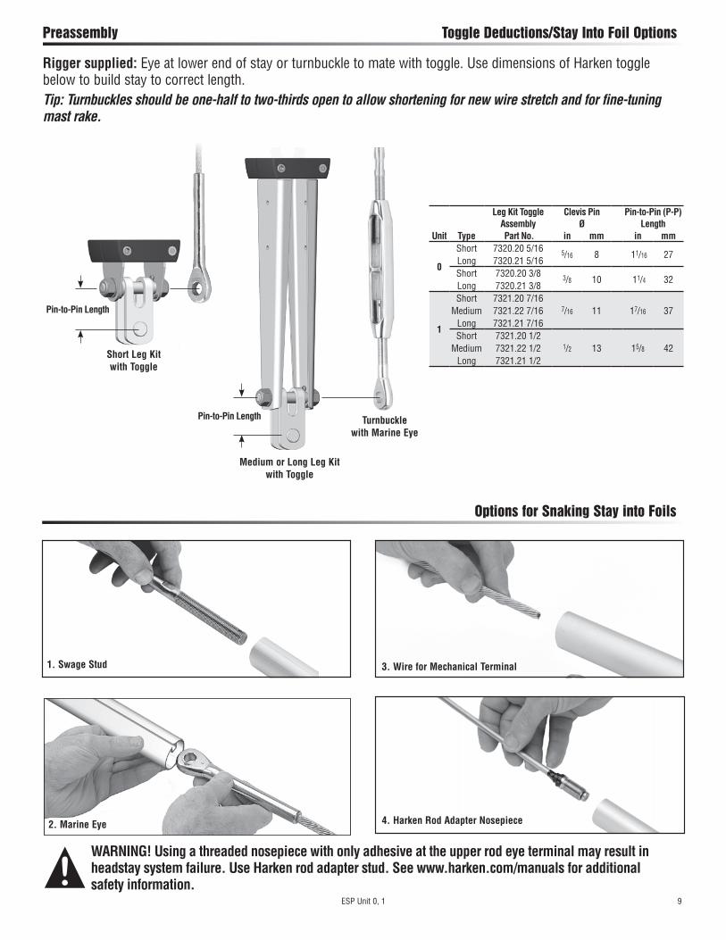
Preassembly Toggle Deductions/Stay Into Foil Options
Options for Snaking Stay into Foils
WARNING! Using a threaded nosepiece with only adhesive at the upper rod eye terminal may result in headstay system failure. Use Harken rod adapter stud. See www.harken.com/manuals for additional safety information.
Unit
Leg Kit Toggle Assembly
Clevis Pin Ø
Pin-to-Pin (P-P) Length
Type Part No. in mm in mm
0
Short 7320.20 5/16 5/16 8 11/16 27Long 7320.21 5/16Short 7320.20 3/8 3/8 10 11/4 32Long 7320.21 3/8
1
Short 7321.20 7/167/16 11 17/16 37Medium 7321.22 7/16
Long 7321.21 7/16Short 7321.20 1/2
1/2 13 15/8 42Medium 7321.22 1/2Long 7321.21 1/2
Medium or Long Leg Kit with Toggle
Pin-to-Pin Length
Short Leg Kit with Toggle
Pin-to-Pin Length
Turnbuckle with Marine Eye
1. Swage Stud
2. Marine Eye
3. Wire for Mechanical Terminal
4. Harken Rod Adapter Nosepiece
Rigger supplied: Eye at lower end of stay or turnbuckle to mate with toggle. Use dimensions of Harken toggle below to build stay to correct length.Tip: Turnbuckles should be one-half to two-thirds open to allow shortening for new wire stretch and for fine-tuning mast rake.
10 ESP Unit 0, 1
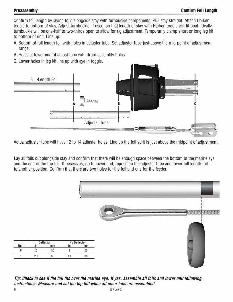
Preassembly Confirm Foil Length
Confirm foil length by laying foils alongside stay with turnbuckle components. Pull stay straight. Attach Harken toggle to bottom of stay. Adjust turnbuckle, if used, so that length of stay with Harken toggle will fit boat. Ideally, turnbuckle will be one-half to two-thirds open to allow for rig adjustment. Temporarily clamp short or long leg kit to bottom of unit. Line up:A. Bottom of full length foil with holes in adjuster tube. Set adjuster tube just above the mid-point of adjustment range.B. Holes at lower end of adjust tube with drum assembly holes.C. Lower holes in leg kit line up with eye in toggle.
Lay all foils out alongside stay and confirm that there will be enough space between the bottom of the marine eye and the end of the top foil. If necessary, go to lower end, reposition the adjuster tube and lower full length foil to another position. Confirm that there are two holes for the foil and one for the feeder.
CBA
Adjuster Tube
Full-Length Foil
Actual adjuster tube will have 12 to 14 adjuster holes. Line up the foil so it is just above the midpoint of adjustment.
Tip: Check to see if the foil fits over the marine eye. If yes, assemble all foils and lower unit following instructions. Measure and cut the top foil when all other foils are assembled.
Feeder
UnitDeflector No Deflector
in mm in mm
0 2 50 1 25
1 2.1 53 1.1 28
ESP Unit 0, 1 11
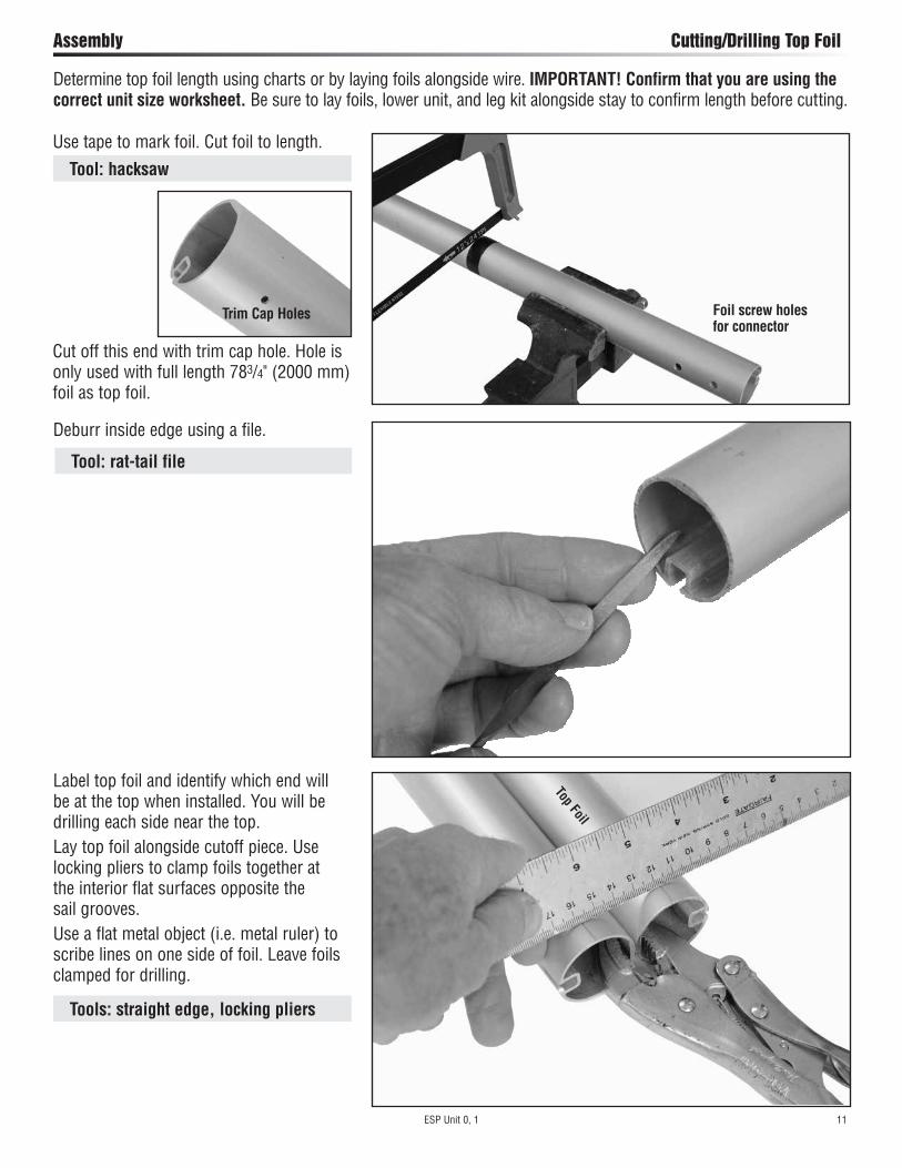
Assembly Cutting/Drilling Top Foil
Deburr inside edge using a file.
Use tape to mark foil. Cut foil to length.
Label top foil and identify which end will be at the top when installed. You will be drilling each side near the top. Lay top foil alongside cutoff piece. Use locking pliers to clamp foils together at the interior flat surfaces opposite the sail grooves. Use a flat metal object (i.e. metal ruler) to scribe lines on one side of foil. Leave foils clamped for drilling.
Determine top foil length using charts or by laying foils alongside wire. IMPORTANT! Confirm that you are using the correct unit size worksheet. Be sure to lay foils, lower unit, and leg kit alongside stay to confirm length before cutting.
Top FoilFoil screw holes for connector
Trim Cap Holes
Cut off this end with trim cap hole. Hole is only used with full length 783/4" (2000 mm) foil as top foil.
Tool: hacksaw
Tool: rat-tail file
Tools: straight edge, locking pliers

12 ESP Unit 0, 1
Assembly Cutting/Drilling Top Foil
Use center punch to start hole. Drill one of two holes for trim cap. Drill Size: 1/8" (3.2 mm)Keeping foils clamped together, flip them to the other side and repeat the procedure so there is a hole on each side.
Measure from the end of the foil and put a mark showing hole distance from top of foil.
Unit
Decimal in
Fraction in
mm
0 .59" 19/32" 151 .98" 1" 25
Top Foil
Top Foil Tool: short tape measure
Tools: electric drill, drill bit, center punch
ESP Unit 0, 1 13
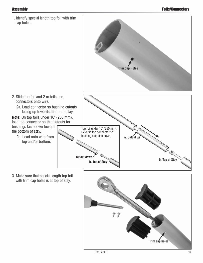
Assembly Foils/Connectors
1. Identify special length top foil with trim cap holes.
2. Slide top foil and 2 m foils and connectors onto wire.
2a. Load connector so bushing cutouts facing up towards the top of stay.
Note: On top foils under 10" (250 mm), load top connector so that cutouts for bushings face down toward the bottom of stay.
2b. Load onto wire from top and/or bottom.
3. Make sure that special length top foil with trim cap holes is at top of stay.
Trim Cap Holes
Trim cap holes
a. Cutout up
b. Top of StayCutout down
Top foil under 10" (250 mm): Reverse top connector so bushing cutout is down.
b. Top of Stay
14 ESP Unit 0, 1
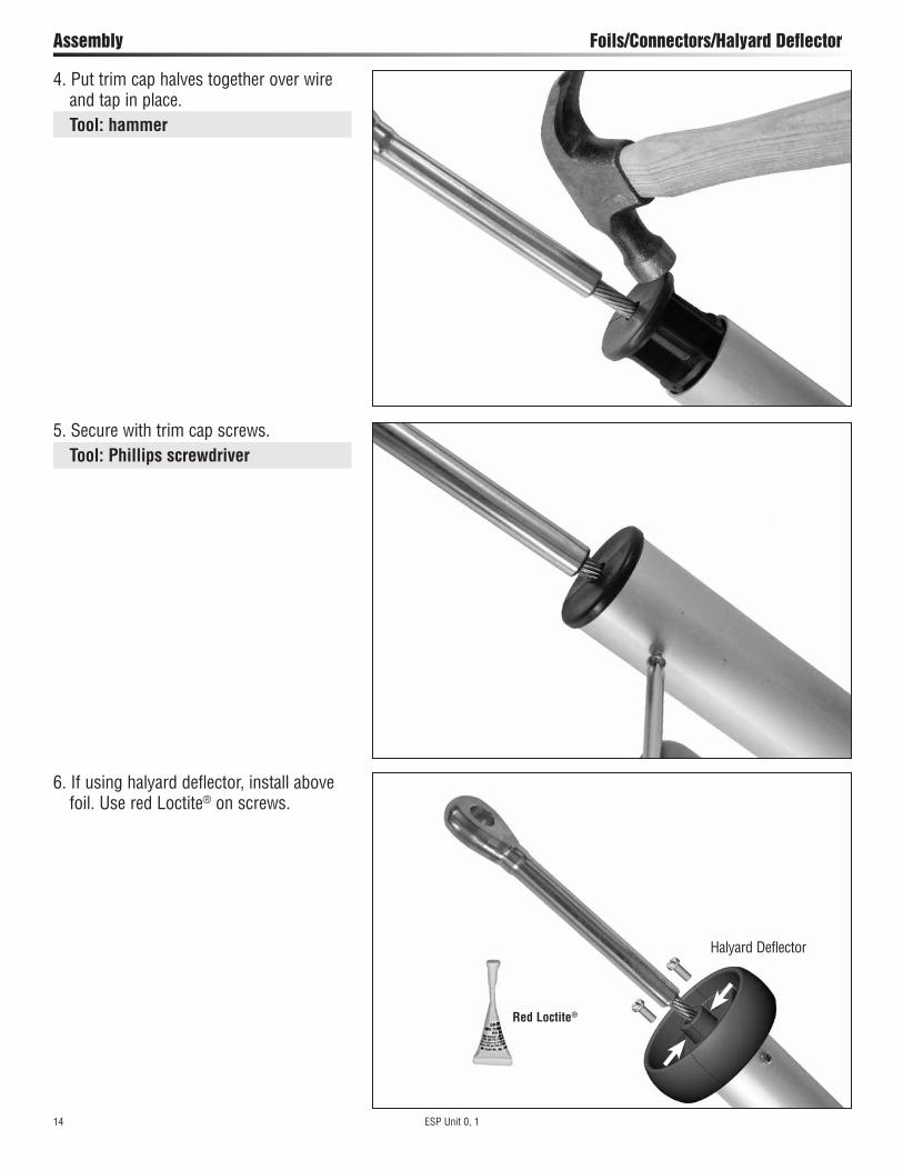
Assembly Foils/Connectors/Halyard Deflector
4. Put trim cap halves together over wire and tap in place. Tool: hammer
5. Secure with trim cap screws. Tool: Phillips screwdriver
6. If using halyard deflector, install above foil. Use red Loctite® on screws.
Halyard Deflector
Red Loctite®
ESP Unit 0, 1 15
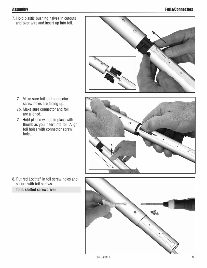
Assembly Foils/Connectors
8. Put red Loctite® in foil screw holes and secure with foil screws. Tool: slotted screwdriver
7. Hold plastic bushing halves in cutouts and over wire and insert up into foil.
7a. Make sure foil and connector screw holes are facing up.7b. Make sure connector and foil are aligned.7c. Hold plastic wedge in place with thumb as you insert into foil. Align foil holes with connector screw holes.
a.
b.
c.
16 ESP Unit 0, 1
Assembly Foils/Connectors
10. Install connector bushings in top of adjuster tube and insert into 2 m foil.
10a. Make sure foil and adjuster tube screw holes are facing up.10b. Make sure adjuster tube and foil are aligned.10c. Do not fasten with foil screws at this time.
b.
a.
9. Join lower part of connector to next foil. Put red Loctite® on screw holes. Secure with foil screws.
Adjuster Tube
ESP Unit 0, 1 17
Assembly Foils/Connectors/Halyard Swivel/Feeder/Drum Assembly
13. Slide feeder onto adjuster tube. Do not secure with screw until later.
12. Slide halyard swivel onto foil so longer part is toward top of stay.
Top
11. Place adjuster tube bushings over wire and insert into foils until tab snaps into holes on either side of adjuster tube. Tap in place.
Top
Tool: hammer
18 ESP Unit 0, 1
Assembly Drum Assembly
15. Put blue Loctite® on screw holes. Secure with adjuster tube clamp screws.
16. Capture jaw/jaw toggle on eye using threaded crosspin.
When using Harken rod adapter stud, be sure to use red Loctite® and cotter pins to lock nosepiece into stud.
14. Slide drum assembly onto adjuster tube.
ESP Unit 0, 1 19
Assembly Leg Kit with Toggle Assembly
18. Secure using cotter pins. Tools: slotted screwdriver, side cutters
17. Slide one spacer on either side of jaw/jaw toggle.
19. Slip leg and washers onto threaded crosspin.
20 ESP Unit 0, 1
Assembly Leg Kit with Toggle Assembly
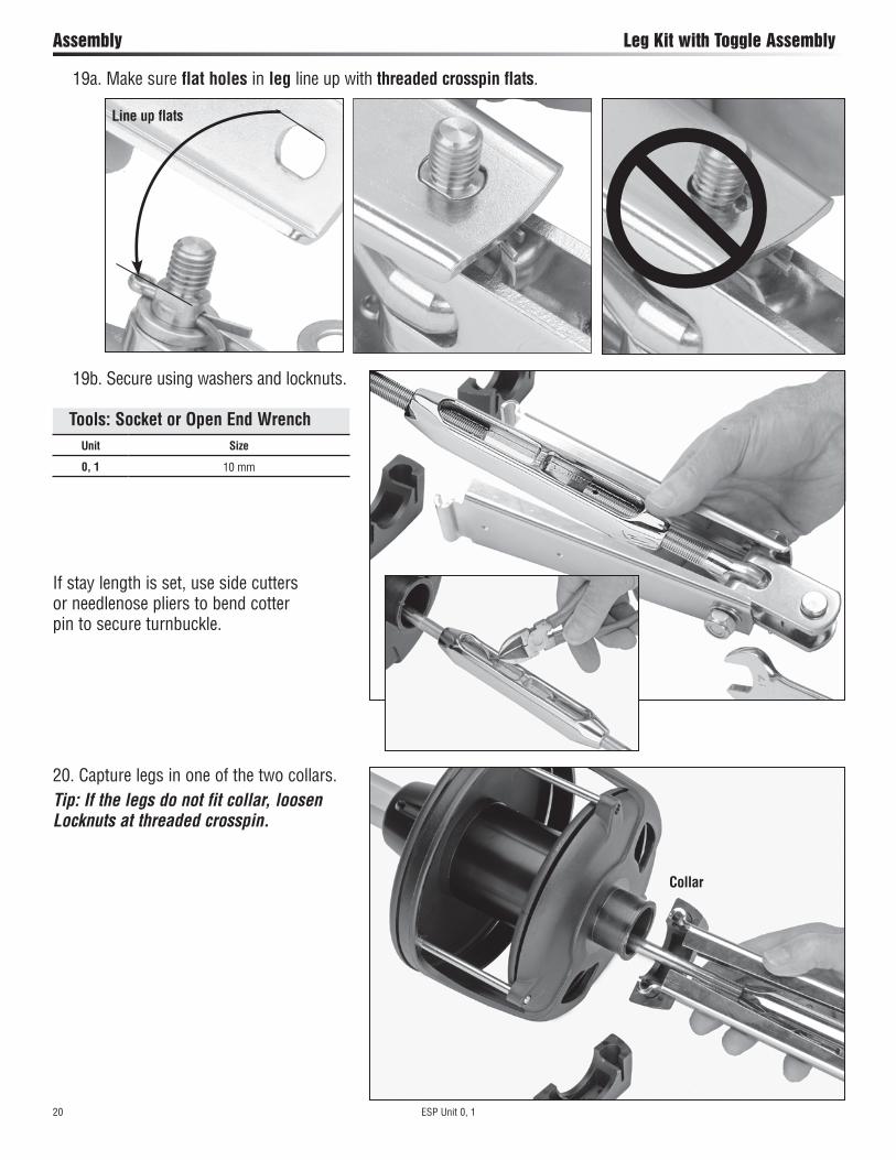
20. Capture legs in one of the two collars.Tip: If the legs do not fit collar, loosen Locknuts at threaded crosspin.
19a. Make sure flat holes in leg line up with threaded crosspin flats.
19b. Secure using washers and locknuts.
If stay length is set, use side cutters or needlenose pliers to bend cotter pin to secure turnbuckle.
Line up flats
Unit Size
0, 1 10 mm
Tools: Socket or Open End Wrench
Collar
ESP Unit 0, 1 21
Assembly Leg Kit with Toggle Assembly
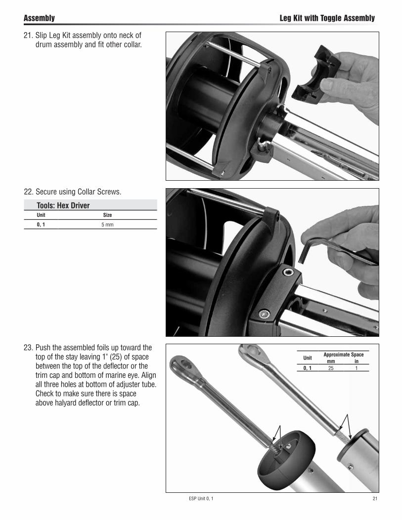
22. Secure using Collar Screws.
Tools: Hex DriverUnit Size
0, 1 5 mm
23. Push the assembled foils up toward the top of the stay leaving 1" (25) of space between the top of the deflector or the trim cap and bottom of marine eye. Align all three holes at bottom of adjuster tube. Check to make sure there is space above halyard deflector or trim cap.
21. Slip Leg Kit assembly onto neck of drum assembly and fit other collar.
UnitApproximate Space
mm in0, 1 25 1

22 ESP Unit 0, 1
Assembly Final
26. Once on boat, loosen collar screws enough to rotate opening in drum assembly towards lead blocks. Put blue Loctite® on screws and tighten.
25. Slide feeder to third hole and secure using foil screw and blue Loctite®. Tool: slotted screwdriver
Tools: Hex DriverUnit Size
0, 1 5 mm
24. Locate nearest group of three screw holes in adjuster tube, two for the foil and one for the feeder. Put blue Loctite® in screw holes. Secure adjuster tube with foil screws. Tool: slotted screwdriver
Blue Loctite®
ESP Unit 0, 1 23
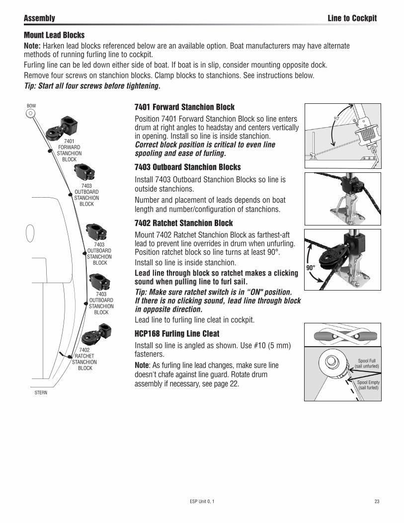
Mount Lead BlocksNote: Harken lead blocks referenced below are an available option. Boat manufacturers may have alternate methods of running furling line to cockpit.Furling line can be led down either side of boat. If boat is in slip, consider mounting opposite dock.Remove four screws on stanchion blocks. Clamp blocks to stanchions. See instructions below.Tip: Start all four screws before tightening.
7403OUTBOARDSTANCHION
BLOCK
7403OUTBOARDSTANCHION
BLOCK
7402RATCHET
STANCHION BLOCK
STERN
BOW
7401FORWARD
STANCHIONBLOCK
7403OUTBOARDSTANCHION
BLOCK
Spool Empty (sail furled)
Spool Full (sail unfurled)
7401 Forward Stanchion BlockPosition 7401 Forward Stanchion Block so line enters drum at right angles to headstay and centers vertically in opening. Install so line is inside stanchion.Correct block position is critical to even line spooling and ease of furling.
7403 Outboard Stanchion BlocksInstall 7403 Outboard Stanchion Blocks so line is outside stanchions.Number and placement of leads depends on boat length and number/configuration of stanchions.
7402 Ratchet Stanchion BlockMount 7402 Ratchet Stanchion Block as farthest-aft lead to prevent line overrides in drum when unfurling.Position ratchet block so line turns at least 90°.Install so line is inside stanchion.Lead line through block so ratchet makes a clicking sound when pulling line to furl sail. Tip: Make sure ratchet switch is in “ON" position. If there is no clicking sound, lead line through block in opposite direction.Lead line to furling line cleat in cockpit.
HCP168 Furling Line CleatInstall so line is angled as shown. Use #10 (5 mm) fasteners.Note: As furling line lead changes, make sure line doesn't chafe against line guard. Rotate drum assembly if necessary, see page 22.
Assembly Line to Cockpit
90°
24 ESP Unit 0, 1
Commissioning Line on Drum Assembly/Storm Sails
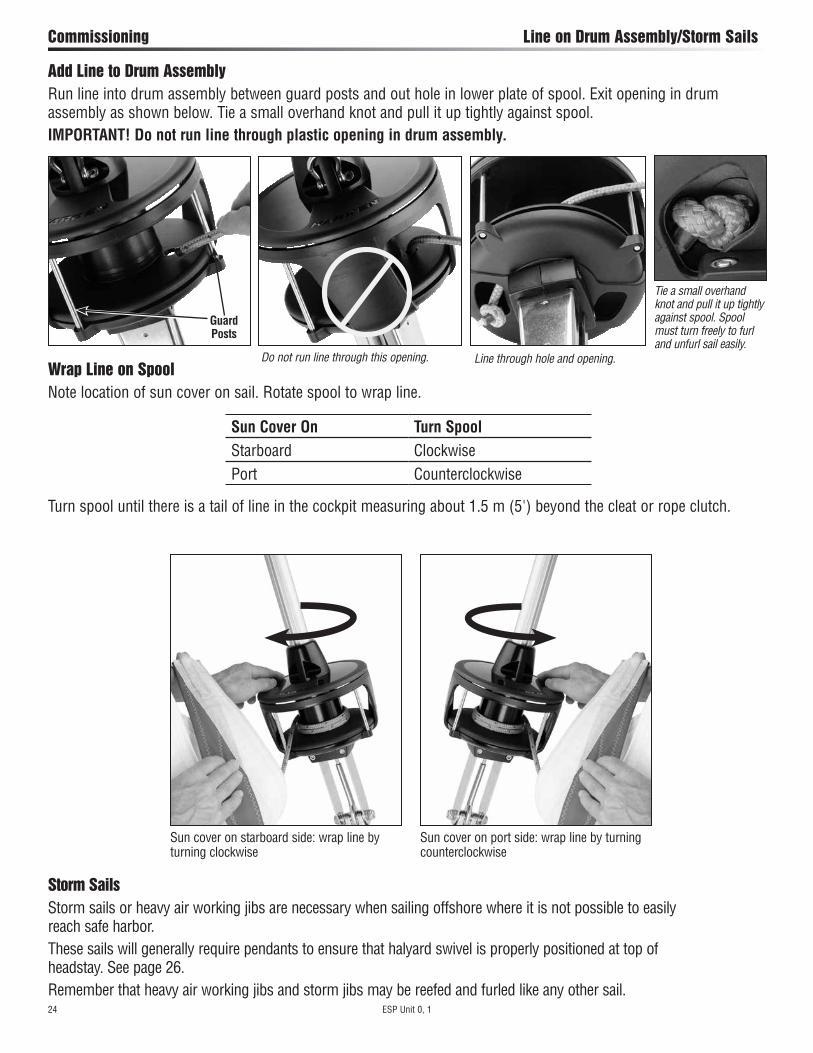
Sun cover on starboard side: wrap line by turning clockwise
Sun cover on port side: wrap line by turning counterclockwise
Storm SailsStorm sails or heavy air working jibs are necessary when sailing offshore where it is not possible to easily reach safe harbor.These sails will generally require pendants to ensure that halyard swivel is properly positioned at top of headstay. See page 26.Remember that heavy air working jibs and storm jibs may be reefed and furled like any other sail.
Add Line to Drum AssemblyRun line into drum assembly between guard posts and out hole in lower plate of spool. Exit opening in drum assembly as shown below. Tie a small overhand knot and pull it up tightly against spool.IMPORTANT! Do not run line through plastic opening in drum assembly.
Sun Cover On Turn SpoolStarboard ClockwisePort Counterclockwise
Turn spool until there is a tail of line in the cockpit measuring about 1.5 m (5') beyond the cleat or rope clutch.
Wrap Line on SpoolNote location of sun cover on sail. Rotate spool to wrap line.
Do not run line through this opening. Line through hole and opening.
Tie a small overhand knot and pull it up tightly against spool. Spool must turn freely to furl and unfurl sail easily.
Guard Posts
ESP Unit 0, 1 25
Commissioning Raise Sail
Raise Sail
Choose conditions with little or no wind when raising sail at the dock. Have bow of boat pointing into the wind. 1) Note: Make sure drum assembly is wrapped with line. Shackle tack of sail to drum. Install shackle so screw pin head is on same side as sun cover. 2) Secure genoa sheets to clew of sail using bowline knot. See www.harken.com/knots or consult a knot-tying book. IMPORTANT! If you are not comfortable tying this or other secure knots, get help from professional rigger. 3) Attach genoa halyard to halyard swivel. 4) Carefully guide sail into feeder and then into foil groove. 5) Attach head or pendant at head of sail to halyard swivel. 6) Hoist sail slowly, making sure luff tape does not jam in foil. IMPORTANT! Forcing sail can cause luff tape to rip.
Tip: New sails are often stiff and may hang up at feeder during raising. Do not force sail when it hangs up—lower and remove twist. Sails "break in" with use and will become easier to raise. 7) Line up front of sail so it is parallel to foil and feeds smoothly when sail is hoisted. 8) Put moderate tension on the halyard and secure. 9) Check the top area of the furler for interference from halyards. See “Check Halyards."10) Practice rolling sail in and out at the dock. See “Furl" and “Unroll Sail."11) If not sailing right away, make sure sail is furled carefully. See “Secure Sail."IMPORTANT! Pay careful attention to “Secure Sail." If leaving the boat, you must secure sail to prevent damage if wind increases while you are away.
WARNING! Sail can become uncontrollable when raising in windy conditions, resulting in loss of footing. Choose wind conditions to match your experience and ability. If changing sails underway, take all safety precautions when working on the foredeck. See www.harken.com/manuals General Warnings and Instructions.
Feeder
Tack
Head
26 ESP Unit 0, 1
Commissioning Check Halyards
Short Luff Length SailIf sail luff is too short to position the halyard swivel 40–100 mm from top of foil assembly, you must add a pendant to the head of sail.Determine Pendant Length1. Raise sail, but do not attach tack to drum assembly.2. Position halyard swivel 40–150 mm from top of foil.3. Secure halyard.4. Tie a piece of rope between sail tack and tack shackle.6. Tension sail.7. Measure distance from tack shackle to sail tack.Have a rigger make a pendant to this length using plastic- coated wire It should be permanently attached to head of sail.
Check HalyardsOnce sail is raised, stand back from boat and use binoculars to make sure there is no interference from halyards. The jib halyard must exert a slight pull to the rear. This allows the foil to turn while halyard remains stationary.1. Halyard swivel must be 40 mm (11/2") –150 mm (6") from top of foil.2. Halyard must pull slightly to rear (8°–10°). Halyard DeflectorIf the stay attachment is close to the halyard exit the halyard will not pull to the rear 8° or more and can catch on the top of the foil. Use halyard deflector to move the halyard away. Check to make sure there is enough space between the trim cap and the bottom of the terminal. Halyard deflector thickness: Unit Part Thickness 0 7301 25.5 mm (1") 1 7302 29 mm (11/8")
WARNING! In severe cases, a halyard wrap can cause loss of control of boat and/or headstay can break suddenly. Make sure halyard is clear of top foil before using system.
8–10°
40–150 mm
Pendant
Head of Sail
40–150 mm
Halyard swivel is too low
The most serious problem with furling systems occurs when the jib halyard wraps around the headstay foil. A halyard wrap will keep you from furling/unfurling and may cause serious damage to the unit and halyard.IMPORTANT! A furler with a low halyard swivel may furl correctly in smooth water/calm conditions, but the halyard will be likely to wrap in a rough sea.
Halyard swivel is too low
If halyard wraps, do not force unit to turn. Attempt to open sail by carefully furling in and out a little at a time. If sail will unfurl, lower it by releasing jib halyard. If sail will not furl, try to remove one sheet and run the tied sheet around foil. Use sheet to pull sail around foil and repeat. This should only be attempted by expert users observing all safety requirements for going forward.

ESP Unit 0, 1 27
Operation Check Halyards
Backstay Adjusters and Halyard TensionBackstay adjusters allow headstay tension to be varied to change sail shape to match conditions. They permit a very tight headstay to be eased when boat is not in use. For best performance, consider adding a backstay adjuster: either a block and tackle, a mechanical adjuster, or hydraulic adjuster like those offered by Harken.Remember to keep headstay tight for best performance when furling or reefing.IMPORTANT! Ease halyard before tensioning backstay adjuster. If not, backstay adjuster will increase halyard tension and could damage the sail or furling system.Racing boats often slack the headstay completely when sailing downwind. Check to be sure that foil does not jam against upper headstay terminal when backstay is released. It may be necessary to shorten foil slightly to prevent this.
Halyard TensionThe jib halyard should be firm, but not too tight.Tip: The foil supports sail along its length so halyard tension is used only to shape sails, not to support them. Use enough halyard tension to remove some wrinkles along luff of sail. Do not tension halyard enough to cause vertical wrinkles in luff of sail. Tension to adjust position of draft in sail to suit sailing conditions. Halyard should be firm but not tight. If in doubt ease halyard tension. To protect sail, ease halyard when boat is not in use.
On many boats it will not be possible to attach the spinnaker halyard to the bow pulpit or it may be "sucked" into jib when furling.On some boats the spinnaker halyard lays across the headstay and will catch on halyard swivel, foils, or jib halyard. Boats with external halyards may find it necessary to flip both ends of spinnaker halyard behind spreaders to prevent fouling with furling system.
Spinnaker HalyardsMake sure spinnaker halyards are clear of furler.
WARNING! In severe cases, spinnaker halyards can jam furler causing loss of control of boat. Make sure all halyards are clear of top of top foil.
Jib Halyard
28 ESP Unit 0, 1
Operation Furl
Unroll SailUncleat furling line. Pull sheets to unfurl sail.IMPORTANT! Keep tension on furling line when unrolling sail so line spools tightly on drum. Use a Harken ratchet block or keep tension on the line by putting a single wrap of the furling line around a spare winch to provide drag on the line. This is very important when wind is blowing over 10 knots. When line is tightly spooled on drum it furls in much easier.
FurlTo furl or reef, ease the jib sheets and pull furling line.In very light breeze, place some tension on jib sheet to insure a tight furl.In a stronger breeze, you must completely luff sail by totally slacking jib sheets before furling.The furling line should pull readily. The amount of force required is related to amount of wind, but a unit should never require use of a winch to furl. If the sail will not furl, or if furling requires a great deal of effort, there is a problem with system. Consult Troubleshoot on page 32. Do not use a winch to force a system to turn. If you are certain that system is operating properly you may use a winch to make furling easier.
ESP Unit 0, 1 29
Operation Reef/Secure Sail
a. 2–3 wraps
b. 2–3 wraps
Secure SailWhen furling the sail completely, make sure sheets and furling line are secured. Check amount of line on the spool compared to the furled sail before using the system.A furled sail must have:
a. Two to three wraps of jib sheet wrapped around sail.b. Two wraps minimum of line wound on spool.c. Furling line securely cleated.d. Jibsheets securely wrapped on winch and held in self-tailing jaws.
Furl at dock with tension on sheets to duplicate furling in high wind.Remember sails furled in light wind and left loosely secured can be a problem if wind increases. IMPORTANT! Remove sail from furler if extreme winds are predicted, especially if boat is left unattended.IMPORTANT! Check all points above—a, b, c, and d—when leaving boat to avoid damage to furler or boat. A loosely rolled sail can catch wind in a storm. Sheets or furling lines can loosen as winds increase and allow furler to unroll. Be sure mooring lines are not placed across furling line where they may cause chafe.IMPORTANT! If no wraps of line are on spool, the line deadend can break the spool when the boat motors through waves.
If you want to:Add more wraps of jibsheet on furled sail. Untie jib sheets and keep sail
completely rolled. Secure with sail tie.
Turn spool to unroll a couple of wraps of line.
Retie sheets.Add more wraps of line on spool.
Turn spool to add a couple of wraps of line.
ReefA sail may be partially furled before you resume sailing. This is known as reefing.Tip: Place marks on foot of sail for a variety of reefed jib sizes. Place marks on jib lead track so lead block position matches reefed jib.Reef sails to balance boat and reduce heel.Tip: Reef sails to improve visibility or to slow boat while sailing in congested areas, or while entering or leaving harbors.
30 ESP Unit 0, 1
Operation Adjust Turnbuckle
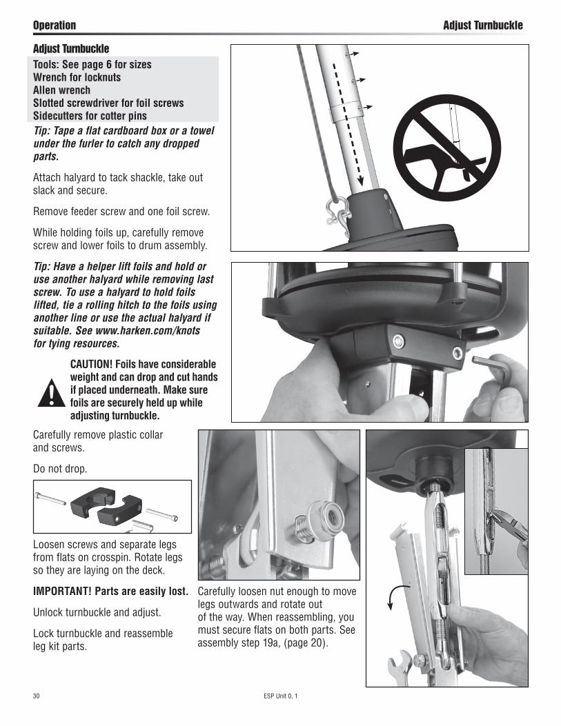
Adjust TurnbuckleTools: See page 6 for sizes Wrench for locknuts Allen wrench Slotted screwdriver for foil screws Sidecutters for cotter pinsTip: Tape a flat cardboard box or a towel under the furler to catch any dropped parts.
Attach halyard to tack shackle, take out slack and secure.
Remove feeder screw and one foil screw.
While holding foils up, carefully remove screw and lower foils to drum assembly.
Tip: Have a helper lift foils and hold or use another halyard while removing last screw. To use a halyard to hold foils lifted, tie a rolling hitch to the foils using another line or use the actual halyard if suitable. See www.harken.com/knots for tying resources.
CAUTION! Foils have considerable weight and can drop and cut hands if placed underneath. Make sure foils are securely held up while adjusting turnbuckle.
Carefully loosen nut enough to move legs outwards and rotate out of the way. When reassembling, you must secure flats on both parts. See assembly step 19a, (page 20).
Carefully remove plastic collar and screws.
Do not drop.
Loosen screws and separate legs from flats on crosspin. Rotate legs so they are laying on the deck.
IMPORTANT! Parts are easily lost.
Unlock turnbuckle and adjust.
Lock turnbuckle and reassemble leg kit parts.
ESP Unit 0, 1 31
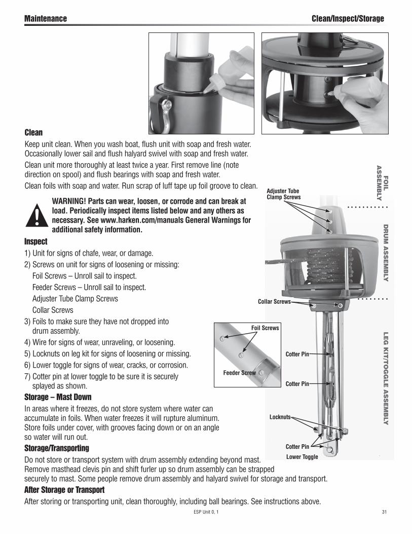
Maintenance Clean/Inspect/Storage
CleanKeep unit clean. When you wash boat, flush unit with soap and fresh water. Occasionally lower sail and flush halyard swivel with soap and fresh water.Clean unit more thoroughly at least twice a year. First remove line (note direction on spool) and flush bearings with soap and fresh water.Clean foils with soap and water. Run scrap of luff tape up foil groove to clean.
WARNING! Parts can wear, loosen, or corrode and can break at load. Periodically inspect items listed below and any others as necessary. See www.harken.com/manuals General Warnings for additional safety information.
Inspect 1) Unit for signs of chafe, wear, or damage.2) Screws on unit for signs of loosening or missing: Foil Screws – Unroll sail to inspect. Feeder Screws – Unroll sail to inspect. Adjuster Tube Clamp Screws Collar Screws3) Foils to make sure they have not dropped into drum assembly.4) Wire for signs of wear, unraveling, or loosening.5) Locknuts on leg kit for signs of loosening or missing.6) Lower toggle for signs of wear, cracks, or corrosion.7) Cotter pin at lower toggle to be sure it is securely splayed as shown.Storage – Mast DownIn areas where it freezes, do not store system where water can accumulate in foils. When water freezes it will rupture aluminum. Store foils under cover, with grooves facing down or on an angle so water will run out.Storage/TransportingDo not store or transport system with drum assembly extending beyond mast. Remove masthead clevis pin and shift furler up so drum assembly can be strapped securely to mast. Some people remove drum assembly and halyard swivel for storage and transport.After Storage or TransportAfter storing or transporting unit, clean thoroughly, including ball bearings. See instructions above.
Adjuster Tube Clamp Screws
Lower Toggle
Collar Screws
Locknuts
Cotter Pin
Feeder Screw
Foil Screws
FO
IL
AS
SE
MB
LYD
RU
M A
SS
EM
BLY
LE
G K
IT/T
OG
GLE
AS
SE
MB
LY
Cotter Pin
Cotter Pin

32 ESP Unit 0, 1
Problem Probable Cause SolutionSail will not furl or unfurl.
Jib halyard is wrapping around the headstay because halyard swivel is too low.
See “Check Halyards" regarding optimal halyard swivel height. A wire pendant may be needed at head of sail to raise halyard swivel to proper height. Use a Halyard Deflector.
Jib halyard is too tight. Ease jib halyard.
Spare halyard is wrapping in sail as it furls. Secure spare halyards away from furling headstay by flipping them behind spreaders. Use a Halyard Deflector.
Salt or dirt in bearings. Flush bearings with fresh water.
Furling line tangled in drum. Overrides are best prevented by using a 7402 ratchet block as the last furling line lead to maintain proper drag on line while unfurling.
Stop knot catching. Make sure knot is a single overhand and is pushed up inside spool.
Sail full of wind. Luff completely before furling or reefing.
Sail flogging too much. Release a short length of sheet, pull some furling line and repeat.
Jib sheets are not free. Free jib sheets.
Foil out of drum assembly. Reinstall foil in drum assembly and tighten adjuster clamp screws into holes.
No wraps of furling line on spool. Remove sheets from furled sail. Rotate spool to wrap correct amount of line.
Line led through ratchet block backwards. Rerun line.
Halyard swivel installed upside down. Remount swivel correctly.
Sail will not furl completely.
Insufficient furling line on drum. Remove sheets. Rotate stay, wrapping as much furling line on drum as possible.
Too much line on drum. Adjust amount of line on drum or change position of forward lead block to allow line to roll evenly on drum.
Spare halyard catching in sail as it furls. Move halyards away from furling headsail as above.
Headstay rotates in jerks or elliptically.
Insufficient tension on headstay. Tighten headstay and/or backstay to eliminate sag in headstay.
Sail does not stay furled.
Sail not furled tightly on stay. Maintain drag on sheets while furling.
Furling line not secure. Secure furling line.
Sail will not go up. Luff tape will not go into groove. Check luff tape for fraying.
Check luff tape size.
Sail catching at feeder. Have someone guide sail into feeder. Purchase prefeeder part no. 947.
Dirt in groove. Clean groove.
Sail will not raise completely or luff will not tension.
Halyard swivel is hitting end stop or trim cap screws.
Luff of sail is too long and must be recut. Consult sailmaker.
Angle between halyard and mast is too sharp and halyard is pulling too much to the rear.
Luff of sail may be too long. Consult sailmaker.
Sail will not come down.
Halyard is wrapping on headstay. Angle between headstay and halyard is too shallow and must be optimized. See commissioning "Halyard Wraps."
Sun cover rolls up inside of sail.
Furling line is wrapped on spool in wrong direction. Unfurl sail and lower it. Disconnect from furler. Note direction of line wrap on spool. Pull line from spool and rewind in opposite direction. Connect sail and hoist. See commissioning section of manual.
Line is wearing on plastic drum assembly
Line is not led through guide posts. Lead line into drum between guide posts.
Troubleshoot Warranty
Loctite® is a trademark of Henkel AG & Company KGaA
Warranty www.harken.com/manuals
or call, write, email or fax Harken, Inc., Pewaukee, WI USA
ESP Unit 0, 1 33
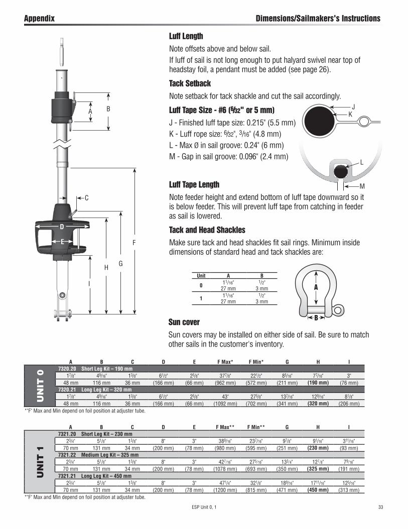
Appendix Dimensions/Sailmakers's Instructions
Luff LengthNote offsets above and below sail.If luff of sail is not long enough to put halyard swivel near top of headstay foil, a pendant must be added (see page 26).
Tack SetbackNote setback for tack shackle and cut the sail accordingly.
Luff Tape Size - #6 (6/32" or 5 mm)J - Finished luff tape size: 0.215" (5.5 mm)K - Luff rope size: 6/32", 3/16" (4.8 mm)L - Max Ø in sail groove: 0.24" (6 mm)M - Gap in sail groove: 0.096" (2.4 mm)
Luff Tape LengthNote feeder height and extend bottom of luff tape downward so it is below feeder. This will prevent luff tape from catching in feeder as sail is lowered.
Tack and Head ShacklesMake sure tack and head shackles fit sail rings. Minimum inside dimensions of standard head and tack shackles are:
A
B
Unit A B
0 11/16" 27 mm
1/2" 3 mm
1 11/16" 27 mm
1/2" 3 mm
Sun coverSun covers may be installed on either side of sail. Be sure to match other sails in the customer's inventory.
A B C D E F Max* F Min* G H I
UN
IT 0
7320.20 Short Leg Kit – 190 mm17/8" 49/16" 13/8" 61/2" 25/8" 377/8" 221/2" 85/16" 77/16" 3"
48 mm 116 mm 36 mm (166 mm) (66 mm) (962 mm) (572 mm) (211 mm) (190 mm) (76 mm)7320.21 Long Leg Kit – 320 mm
17/8" 49/16" 13/8" 61/2" 25/8" 43" 275/8" 137/16" 129/16" 81/8"48 mm 116 mm 36 mm (166 mm) (66 mm) (1092 mm) (702 mm) (341 mm) (320 mm) (206 mm)
*"F" Max and Min depend on foil position at adjuster tube.
A B C D E F Max** F Min** G H I
UN
IT 1
7321.20 Short Leg Kit – 230 mm 23/4" 51/8" 13/8" 8" 3" 389/16" 237/16" 97/8" 91/16" 311/16"
70 mm 131 mm 34 mm (200 mm) (78 mm) (980 mm) (595 mm) (251 mm) (230 mm) (93 mm)7321.22 Medium Leg Kit – 325 mm
23/4" 51/8" 13/8" 8" 3" 427/16" 275/16" 133/4" 127/8" 79/16"70 mm 131 mm 34 mm (200 mm) (78 mm) (1078 mm) (693 mm) (350 mm) (325 mm) (191 mm)
7321.21 Long Leg Kit – 450 mm 23/4" 51/8" 13/8" 8" 3" 471/4" 321/8" 189/16" 1711/16" 125/16"
70 mm 131 mm 34 mm (200 mm) (78 mm) (1200 mm) (815 mm) (471 mm) (450 mm) (313 mm)*"F" Max and Min depend on foil position at adjuster tube.
D
F
G
I
C
H
E
BAJ
K
L
M
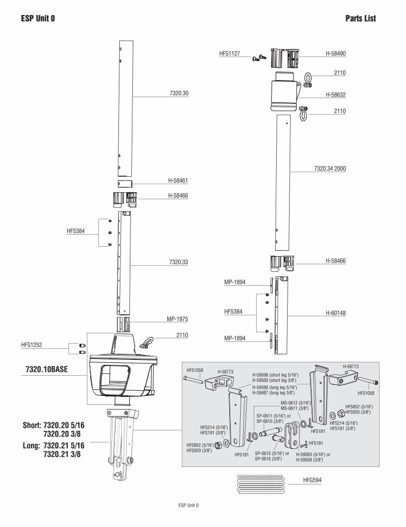
ESP Unit 0
ESP Unit 0 Parts List
HFG594
7320.10BASE
2110
2110
2110
H-58632
H-58490HFS1127
HFS384
7320.34 2000
H-58466
H-58466
H-58461
HFS1252
MP-1894
HFS384
MP-1894
H-60148
Short: 7320.20 5/16 7320.20 3/8Long: 7320.21 5/16 7320.21 3/8
7320.33
MP-1975
HFS1058 H-58773H-59598 (short leg 5/16") H-59500 (short leg 3/8")
HFS852 (5/16") HFS920 (3/8")
HFS214 (5/16") HFS191 (3/8")
HFS181
SP-0611 (5/16") or SP-0610 (3/8")
SP-0615 (5/16") orSP-0616 (3/8")
H-59583 (5/16") or H-59508 (3/8")
HFS1058
H-58773
HFS852 (5/16") HFS920 (3/8")
HFS214 (5/16") HFS191 (3/8")HFS181
HFS181
MS-0612 (5/16") MS-0611 (3/8")
H-59590 (long leg 5/16")H-59487 (long leg 3/8")
7320.30
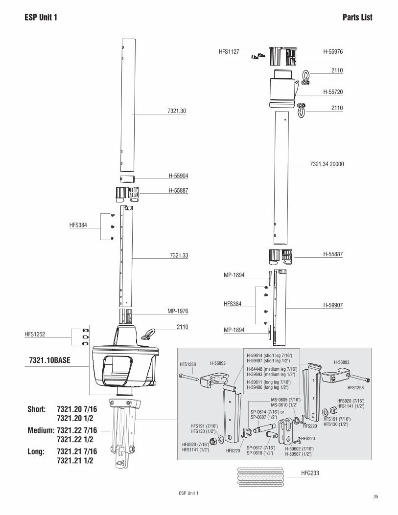
35 ESP Unit 1
ESP Unit 1 Parts List
HFG233
2110
2110
2110
H-55720
H-55976HFS1127
HFS384
7321.34 20000
H-55887
H-55887
H-55904
MP-1894
HFS384
MP-1894
H-59907
Short: 7321.20 7/16 7321.20 1/2
Medium: 7321.22 7/16 7321.22 1/2
Long: 7321.21 7/16 7321.21 1/2
7321.33
MP-1976
7321.10BASE
HFS1252
HFS1258 H-56893
HFS920 (7/16") HFS1141 (1/2")
HFS191 (7/16")HFS130 (1/2")
HFS220
SP-0614 (7/16") or SP-0607 (1/2")
SP-0617 (7/16") SP-0618 (1/2")
H-59602 (7/16") H-59507 (1/2")
HFS1258
H-56893
HFS920 (7/16") HFS1141 (1/2")
HFS191 (7/16") HFS130 (1/2")
H-59614 (short leg 7/16")H-59497 (short leg 1/2")
H-64448 (medium leg 7/16")H-59693 (medium leg 1/2")
H-59611 (long leg 7/16")H-59486 (long leg 1/2")
HFS220
HFS220
MS-0605 (7/16") MS-0610 (1/2"
7321.30
Corporate HeadquartersN15W24983 Bluemound Rd, Pewaukee, WI 53072 USA
Telephone: (262) 691-3320 • Fax: (262) 701-5780Web: www.harken.com • Email: [email protected]
Harken Australia Pty, Ltd.1B Green Street, Brookvale, N.S.W. 2100, Australia
Telephone: (61) 2-8978-8666 • Fax: (61) 2-8978-8667Web: harken.com.au • Email: [email protected]
Harken FranceZA Port des Minimes, BP 3064, 17032 La Rochelle Cedex 1, France
Telephone: (33) 05.46.44.51.20 • Fax: (33) 05.46.44.25.70Web: harken.fr • Email: [email protected]
Harken Italy S.p.A.Via Marco Biagi, 14, 22070 Limido Comasco (CO) Italy Telephone: (39) 031.3523511 • Fax: (39) 031.3520031
Web: harken.it • Email: [email protected]
Harken New Zealand, Ltd.158 Beaumont Street
Unit 11, Orams Marine CentreWesthaven, Aukland, 1010, New Zealand
Telephone: (64) 9-303-3744 • Fax: (64) 9-307-7987Web: harken.co.nz • Email: [email protected]
Harken Polska Sp. z o.o.ul. Przasnyska 6A, 01-756, Warszawa, PolandTel: +48 22 561 93 93 • Fax: +48 22 839 22 75
Web: harken.pl • Email: [email protected]
Harken Sweden ABMain Office and Harken Brandstore: Västmannagatan 81B
SE-113 26 Stockholm SwedenTelephone: (46) 0303 61875 • Fax: (46) 0303 61876
Mailing address: Harken Sweden AB, Box 64, SE -440 30 MarstrandWeb: harken.se • Email: [email protected]
Harken UK, Ltd.Bearing House, Ampress Lane, Lymington, Hampshire S041 8LW, England
Telephone: (44) 01590-689122 • Fax: (44) 01590-610274Web: harken.co.uk • Email: [email protected]
Please visit: http://www.harken.com/locator.aspx to locate Harken dealers and distributors
Printed in USA 5002 01/20