
ESIS TC24, Politecnico di Milano, 1 - 2 October...
26
© Fraunhofer ESIS TC24, Politecnico di Milano, 1 st -2 nd October 2014 Potential improvements of the presently applied in-service inspection of wheelset axles Wolfgang Kappes, Fraunhofer IZFP
-
Upload
nguyenkhue -
Category
Documents
-
view
217 -
download
4
Transcript of ESIS TC24, Politecnico di Milano, 1 - 2 October...

© Fraunhofer
ESIS TC24, Politecnico di Milano, 1st - 2nd October 2014
Potential improvements of the presently applied
in-service inspection of wheelset axles
Wolfgang Kappes, Fraunhofer IZFP
© Fraunhofer
State of the art of the presently applied inspection technology for
hollow axles and solid axles
Conclusion from the Gap Analysis related to in-service inspection
Identification of possible improvements
o Ultrasonic Phased Array technique
o Synthetic Aperture Focusing Technique - SAFT
o POD Simulation for axle testing
o Induction Thermography for surface crack detection
o Condition Monitoring
Outline of the Presentation

© Fraunhofer
Hollow Axle Testing - Relevant Areas and Defect Types
Wheel seat Brake disk seatShaft
Axle journal
Dust guard seat Transversal and longitudinal
defects in outer surface
Internal defects
State-of-the-art for the Inspection of Axles in Service
© Fraunhofer
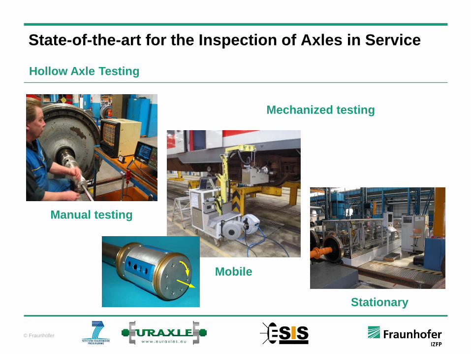
State-of-the-art for the Inspection of Axles in Service
Manual testing
Mechanized testing
Mobile
Stationary
Hollow Axle Testing
© Fraunhofer
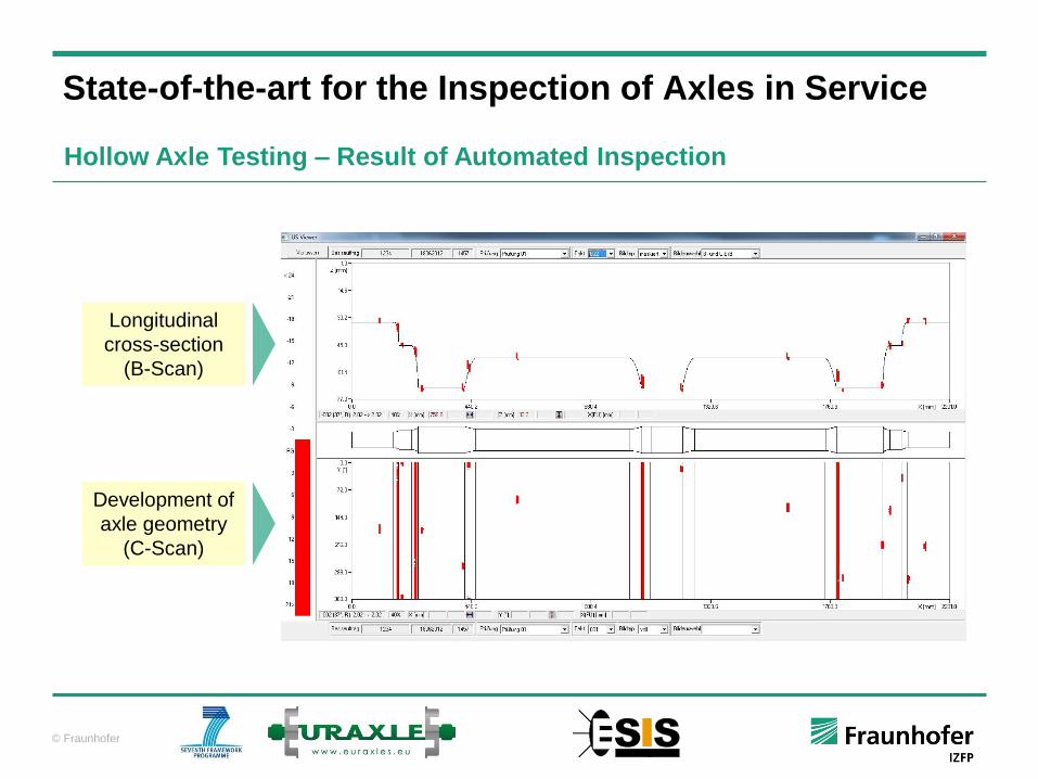
Development of
axle geometry
(C-Scan)
Longitudinal
cross-section
(B-Scan)
State-of-the-art for the Inspection of Axles in Service
Hollow Axle Testing – Result of Automated Inspection

© Fraunhofer
State-of-the-art for the Inspection of Axles in Service
Solid Axle Testing – Scanning Techniques
Axial scanning using normal beam probes
Detection of transversal
cracks in axle journal and in
the rear bearing inner ring
Axle inspection with various fixed
angle beam probes
Scanning pattern for the inspection with
conventional fixed angle beam probes
Axle inspection with various fixed angle beam probes
at the same time without longitudinal scanning
Axial scanning using
phased array probes

© Fraunhofer
State-of-the-art for the Inspection of Axles in Service
Solid Axle Testing
Manual testing
Mechanized testing
Fully automatic testing
© Fraunhofer
Conclusions from the EURAXLES Gap Analysis
Replacement of manual testing by automated testing to ensure reliability and
repeatability, reduce human errors, improve throughput, allow for automatic
documentation and data storage
Improvement of sensitivity without increasing the false calls rate
Differentiation between critical and non-critical surface imperfections
Differentiation between geometrical echoes and defect echoes
Improvement of the spatial resolution especially in the cross-sectional transition areas
where the probability of crack initiation is high
Defect characterization with respect to size, orientation and type in order to evaluate
the consequences on the axle’s remaining life time (NDE)
Establishing methods for condition monitoring of axles as a basis for safety increase
and condition-based maintenance
© Fraunhofer
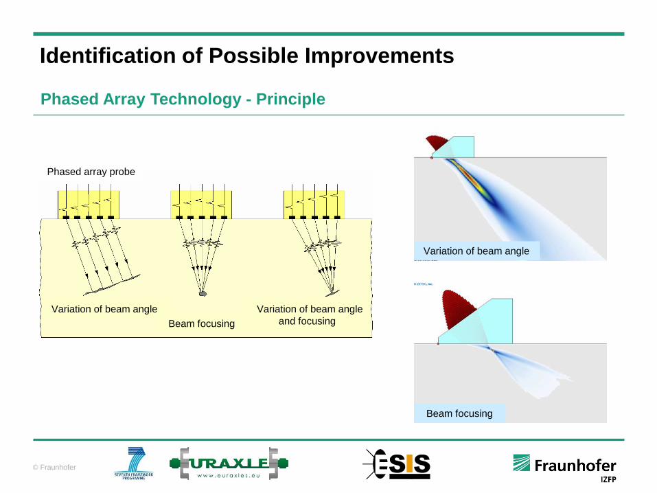
Identification of Possible Improvements
Phased Array Technology - Principle
Beam focusing
Variation of beam angle
and focusing
Phased array probe
Variation of beam angle
Variation of beam angle
Beam focusing

© Fraunhofer
Identification of Possible Improvements
Phased Array Technology – End face Solid Axle Testing System
Solid axle ultrasonic inspection from the
axle’s end face
Fully-automatic mobile inspection system
using phased arrays
Application in light and heavy maintenance
Suitable for all types of solid axles for
rolling stock and metro vehicles
2 minutes inspection time excluding
bearing cap disassembly
© Fraunhofer
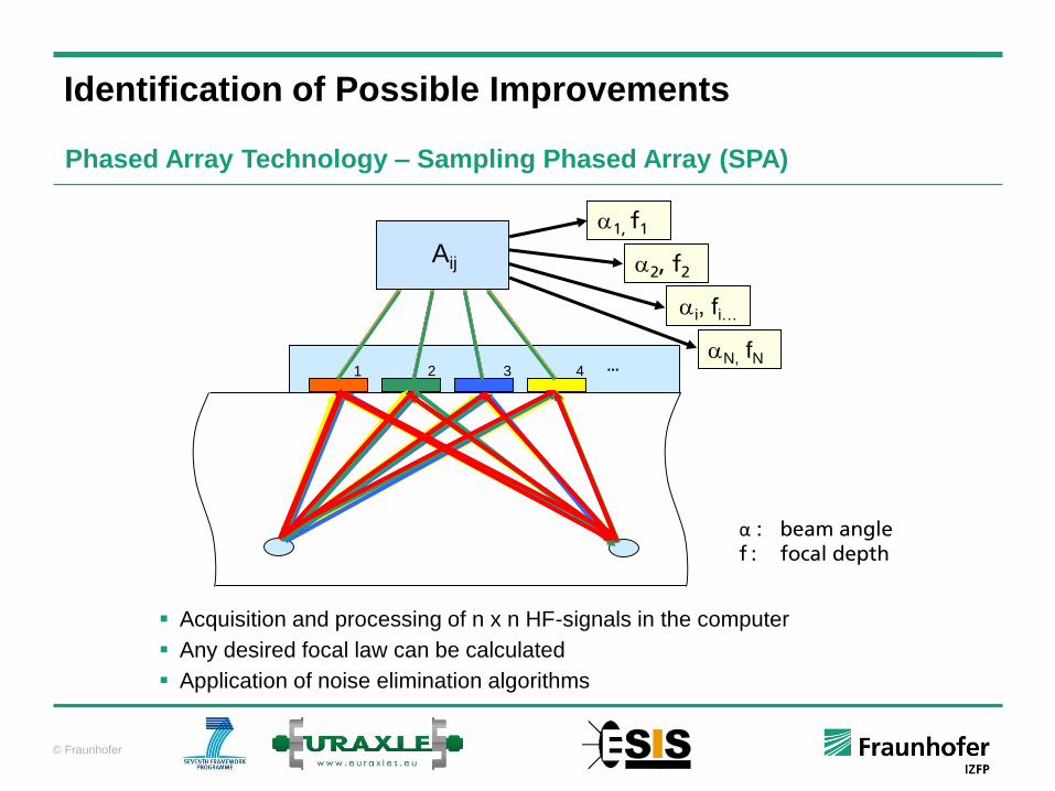
... 2 3 41
1, f1
2, f2
i, fi…
N, fN
Aij
α : beam angle
f : focal depth
Acquisition and processing of n x n HF-signals in the computer
Any desired focal law can be calculated
Application of noise elimination algorithms
Identification of Possible Improvements
Phased Array Technology – Sampling Phased Array (SPA)
© Fraunhofer
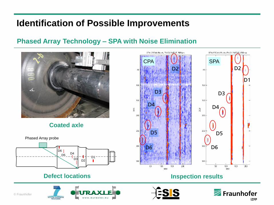
Identification of Possible Improvements
Phased Array Technology – SPA with Noise Elimination
D1D2
D3
D4D5
D6
Phased Array probe
Coated axle
Defect locations Inspection results
D2
D3
D4
D5
D6
D1
D2
D3
D4
D5
D6
CPA SPA

© Fraunhofer
Identification of Possible Improvements
Phased Array Technology – SPA for the Inspection of Coated Axles
Coating with RELEST® Protect Wheel
by BASF
Coating thickness ~ 2 mm
No removal of coating for UT inspection
Sensitivity should not be influenced by
the coating
High-angle scanning on the train with a
mobile SPA-based system in
combination with visual testing according
to EVIC
© Fraunhofer
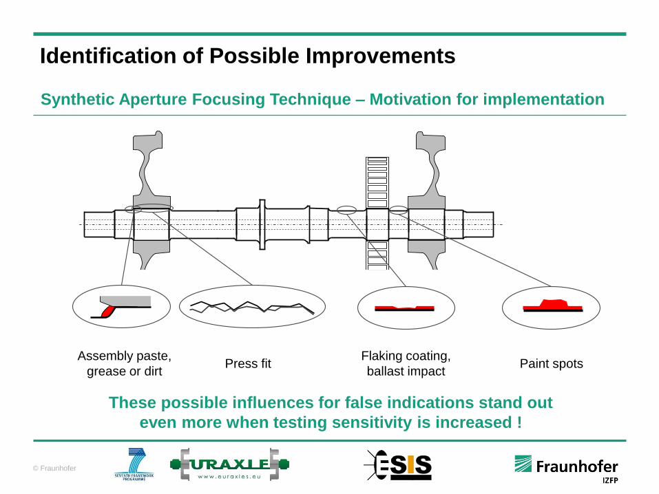
These possible influences for false indications stand out
even more when testing sensitivity is increased !
Assembly paste,
grease or dirtPress fit
Flaking coating,
ballast impactPaint spots
Identification of Possible Improvements
Synthetic Aperture Focusing Technique – Motivation for implementation
© Fraunhofer
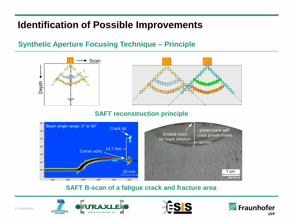
Identification of Possible Improvements
Synthetic Aperture Focusing Technique – Principle
Corner echo14,7 mm
Eroded notch
for crack initiation
grown crack with
crack growth marks
15 mm
10 mm
Crack tipBeam angle range: 0° to 60°
Scan
Dep
th
SAFT B-scan of a fatigue crack and fracture area
SAFT reconstruction principle
© Fraunhofer
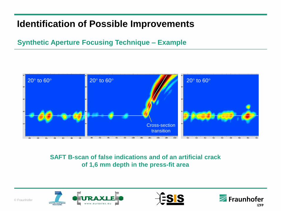
a)20° to 60° 20° to 60°
Cross-section
transition
20° to 60°
Identification of Possible Improvements
Synthetic Aperture Focusing Technique – Example
SAFT B-scan of false indications and of an artificial crack
of 1,6 mm depth in the press-fit area

© Fraunhofer
Identification of Possible Improvements
POD Simulation for Axle Testing – Replacing Experiments by Simulation
Definition of inspection intervals
POD for various testing procedure
applied at solid axles
© Fraunhofer
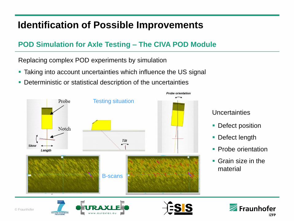
Replacing complex POD experiments by simulation
Taking into account uncertainties which influence the US signal
Deterministic or statistical description of the uncertainties
Defect position
Defect length
Probe orientation
Grain size in the
material
Uncertainties
Testing situation
B-scans
Identification of Possible Improvements
POD Simulation for Axle Testing – The CIVA POD Module
© Fraunhofer
Identification of Possible Improvements
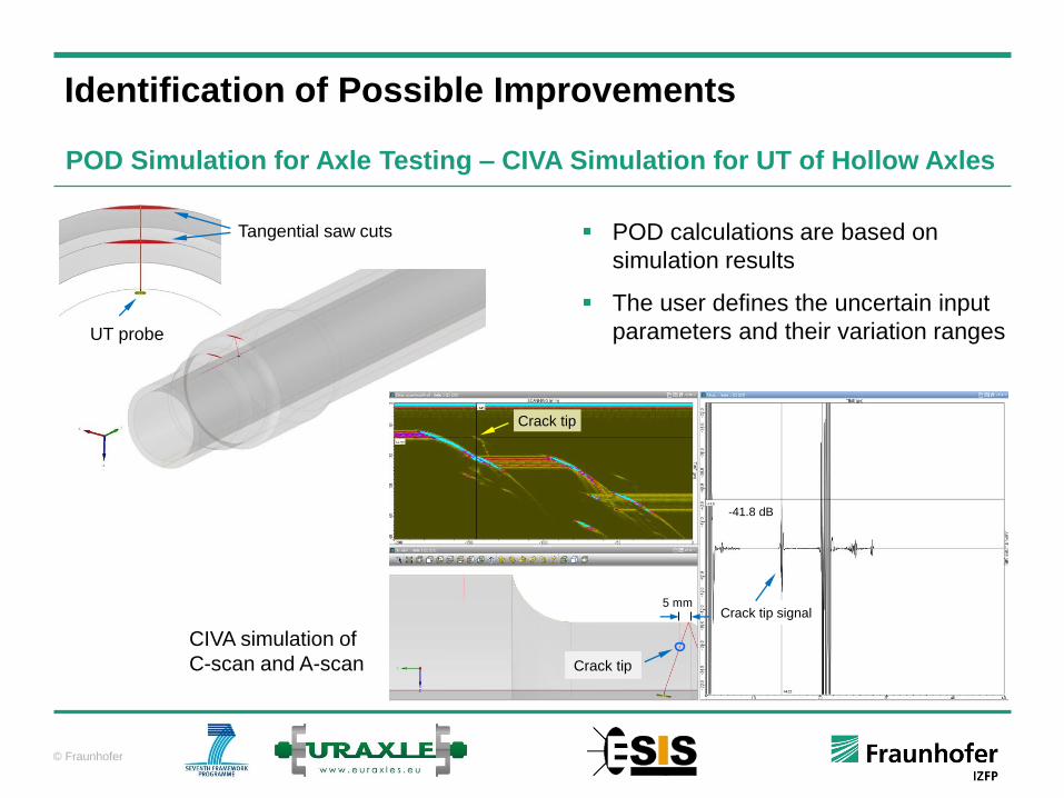
POD Simulation for Axle Testing – CIVA Simulation for UT of Hollow Axles
UT probe
Tangential saw cuts
Crack tip
-41.8 dB
5 mmCrack tip signal
Crack tip
POD calculations are based on
simulation results
The user defines the uncertain input
parameters and their variation ranges
CIVA simulation of
C-scan and A-scan
© Fraunhofer
Identification of Possible Improvements
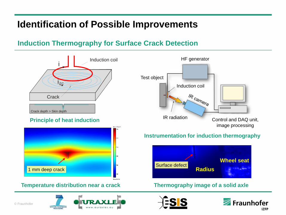
Induction Thermography for Surface Crack Detection
Crack
iInduction coil
iEC
Radius
Wheel seat
1 mm deep crack
Thermography image of a solid axle
Surface defect
Principle of heat induction
Temperature distribution near a crack
Instrumentation for induction thermography
Test object
Induction coil
IR radiation Control and DAQ unit,
image processing
HF generator
Crack depth > Skin depth
© Fraunhofer
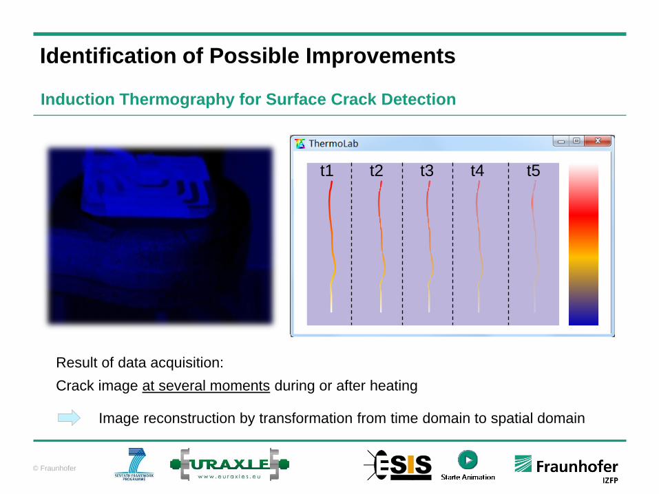
Identification of Possible Improvements
Induction Thermography for Surface Crack Detection
t1 t2 t3 t4 t5
Result of data acquisition:
Crack image at several moments during or after heating
Image reconstruction by transformation from time domain to spatial domain
© Fraunhofer
Calculation of the failure probability of an axle cannot consider real loads which act
on the axle during its operational life
Consideration of specific dynamic loads dependent on axle application, railway line
characteristics, environmental conditions is only partly possible
Non-predictable events like impacts from ballast, corrosion, obstacles on the rail, etc.
cannot be considered in the life-time calculation models
Identification of Possible Improvements
Condition Monitoring – Motivation for its Implementation
Condition Monitoring can be an important tool for
condition-based maintenance and increase of safety!
© Fraunhofer
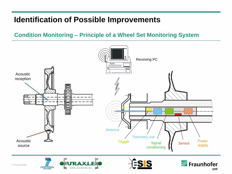
Identification of Possible Improvements
Condition Monitoring – Principle of a Wheel Set Monitoring System
Receiving PC
Power
supplySensorSignal
conditioning
Telemetry unit
Trigger
Antenna
Acoustic
source
Acoustic
reception

© Fraunhofer
Monitoring system in test vehicle
Hollow axle sensor system
Sensor system inside the hollow shaft
with removed bearing cap
Condition Monitoring of Wheel Sets
signal processing unit
and data memory
sensor module
TX/RX radio interface

© Fraunhofer
UT probe
UT probe
Cracks
Identification of Possible Improvements
Condition Monitoring – Detection of Transversal Cracks
Detection sensitivity for periodic inspection ~ 2 mm deep crack
Requirements regarding detection sensitivity for a condition monitoring system?
© Fraunhofer
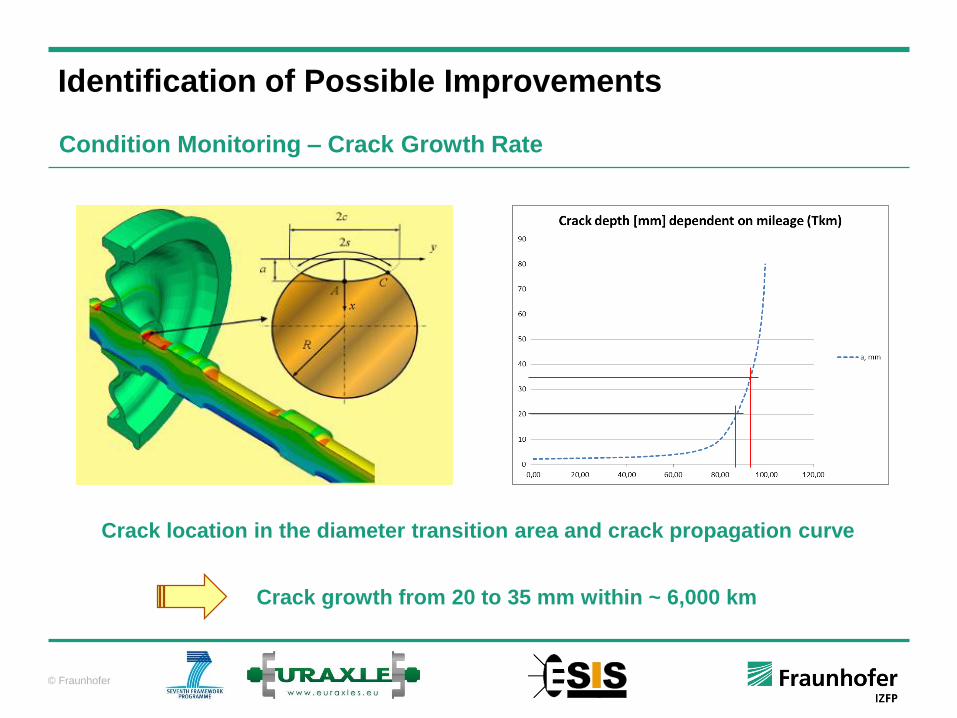
Identification of Possible Improvements
Condition Monitoring – Crack Growth Rate
Crack location in the diameter transition area and crack propagation curve
Crack growth from 20 to 35 mm within ~ 6,000 km


![AN EMIS GUIDE FOR ESIS - eSMOC - eSIS …esmoc.oecn.k12.oh.us/restricted/documentation/eSMOC/... · Web viewELA Levels [GI] English Language Assessment (OCT) – (speaking, listening,](https://static.fdocuments.in/doc/165x107/5ab651787f8b9ab7638d96ee/an-emis-guide-for-esis-esmoc-esis-esmocoecnk12ohusrestricteddocumentationesmocweb.jpg)
