ESCON-A® FERRO-SHIELD™ _Brochure
4
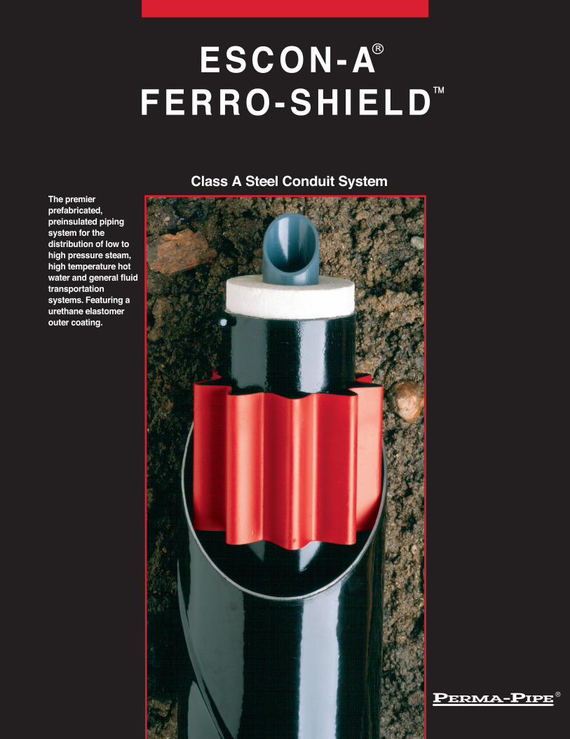
The premier prefabricated, preinsulated piping system for the distribution of low to high pressure steam, high temperature hot water and general fluid transportation systems. Featuring a urethane elastomer outer coating. Class A Steel Conduit System ESCON-A FERRO-SHIELD R TM
-
Upload
avin-gidwani -
Category
Documents
-
view
13 -
download
0
description
The premier prefabricated, preinsulated piping system for the distribution of low to high pressure steam,high temperature hot water and general fluid transportation systems. Featuring a urethane elastomer outer coating.
Transcript of ESCON-A® FERRO-SHIELD™ _Brochure
The premier prefabricated, preinsulated piping system for the distribution of low to high pressure steam, high temperature hot water and general fluid transportation systems. Featuring a urethane elastomer outer coating.
Class A Steel Conduit System
ESCON-AFERRO-SHIELD
R
TM
ESCON-A/FERRO-SHIELDWhy? There is not a more cost effective means of conveying fl uids and gases below grade, at temperatures above 250°F, than a DDT (Drainable, Dryable and Testable) air gap piping system.
Why are these features important to an engineer or system owner?A system that is drainable speeds the recovery of fl uids in the event of moisture entering the system during installation or in the event of a leak. The dryable feature allows for the entire system, including the insulation, to be dried in place in the trench. The testable feature insures that the entire system is airtight right from the start. This testable feature applies to all fi ttings, anchors, end terminations and fi eld joints. No other system supplied for fl uids above 250°F can provide this type of integrity.
What else is important in a DDT system? The thermal movement of the service pipe is critical. The system has to be designed so that no undue stresses are caused to the service pipe. The design of a DDT system allows the service pipe to expand within the outer conduit, thus eliminating stress to the outer conduit. There is no damage to the service pipe insulation. This cannot be said for non-air gap systems.
The DDT system outer coating is another important area in the design of a DDT system. The conduit coating should be designed to operate effectively in wet environments. The coating should provide the same protection at the fi tting assemblies as for the straight sections of the piping system. Any coating that cannot handle the temperature in wet environments should be avoided. No cathodic protection system can be designed to protect a bad coating choice. PERMA-PIPE’s elastomer coating provides the protection needed to perform in these critical environments.
Urethane Elastomer CoatingThis state-of-the-art coating provides an outstanding corrosion resistant covering for the underground steel conduit system. (Contact PERMA-PIPE for the appropri-ate coating system for aboveground applications.) The coating is applied hot over the shot-blasted steel casing at PERMA-PIPE’s factory to meet rigid quality standards.
Fully Insulated Pipe Supports The piping system is supported utilizing insulated supports at 10-foot intervals that maintain and guide the service pipe in the center of the conduit casing. PERMA-PIPE’s support design permits full insulation o f the service pipe f o r optimum thermal effi ciency, whi le maximizing drainabi l i ty and dryabi l i ty of the piping system. The support design also permits the in-stallation of a cable type leak detection/location system.
SYSTEM FEATURES
Electric or Steam Heat Trace (Optional)
Cathodic Protection System (Optional)
Dryable Insulation The service pipe is insulated with your choice of today’s thermally effi cient dryable insulations.
Computer Aided Engineering and Design Over forty years of experience has made PERMA-PIPE the leader in the design of prefabricated systems. PER-MA-PIPE’s proprietary CAD programs encompass the major design parameters of the piping systems, including service pipe stress, heat transfer and soil loading. Be as-sured that the engineering behind your distribution system is state-of-the-art.
Industrial & Municipal Steam Transmission Geothermal Collection & Distribution District Heating Cogeneration Process Fluid Transport Transportation of Fuel & Heavy Oil Solar Collection & Distribution
ESCON-A / FERRO-SHIELDAPPLICATIONS
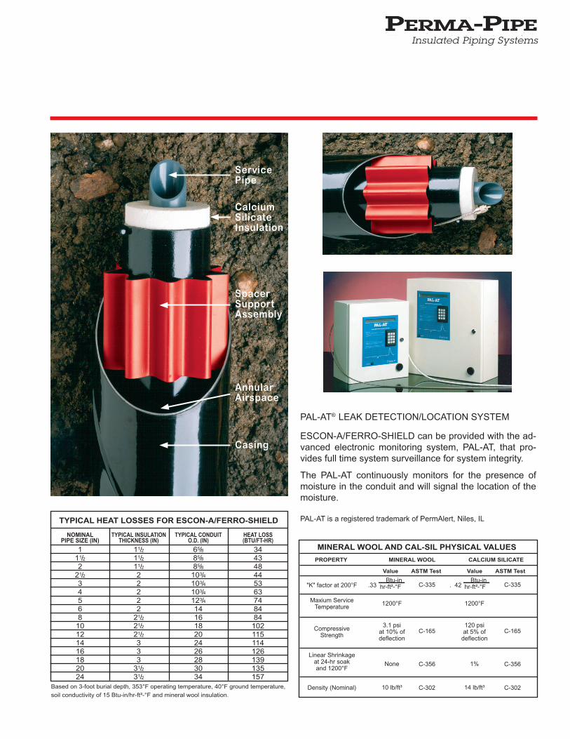
PAL-AT® LEAK DETECTION/LOCATION SYSTEM
ESCON-A/FERRO-SHIELD can be provided with the ad-vanced electronic monitoring system, PAL-AT, that pro-vides full time system surveillance for system integrity.
The PAL-AT continuously monitors for the presence of moisture in the conduit and will signal the location of the moisture. PAL-AT is a registered trademark of PermAlert, Niles, IL
NOMINALPIPE SIZE (IN)
111/22
21/23456810121416182024
TYPICAL INSULATIONTHICKNESS (IN)
11/211/211/222222
21/221/221/2333
31/231/2
TYPICAL CONDUITO.D. (IN)
65/885/885/8
103/4103/4103/4123/4141618202426283034
HEAT LOSS(BTU/FT-HR)
344348445363748484102115114126139135157
TYPICAL HEAT LOSSES FOR ESCON-A/FERRO-SHIELD
Based on 3-foot burial depth, 353°F operating temperature, 40°F ground temperature,
soil conductivity of 15 Btu-in/hr-ft²-°F and mineral wool insulation.
Insulated Piping Systems
PROPERTY
"K" factor at 200°F
Maxium ServiceTemperature
CompressiveStrength
Linear Shrinkageat 24-hr soakand 1200°F
Density (Nominal)
MINERAL WOOL AND CAL-SIL PHYSICAL VALUESCALCIUM SILICATE
Value ASTM Test
MINERAL WOOL
Value ASTM Test
.33
1200°F
3.1 psiat 10% ofdeflection
None
10 lb/ft³
C-335
C-165
C-356
C-302
C-335
C-165
C-356
C-302
. 42
1200°F
120 psiat 5% of
deflection
1%
14 lb/ft³
Btu-in hr-ft²-°F
Btu-in hr-ft²-°F
ServicePipe
CalciumSilicateInsulation
Annular Airspace
SpacerSupportAssembly
Casing
GENERALAll underground fl uid, steam, hot water, oil and condensate lines, as indicated on contract drawings, shall be drainable and dryable ESCON-A/FERRO-SHIELD type as manufactured by PERMA-PIPE. All straight sections, fi ttings, anchors and other accessories shall be factory prefab-ricated to job dimensions and designed to minimize the number of fi eld welds. Each system layout shall be computer analyzed by the piping system manufacturer to determine stresses on the service pipe and anticipated thermal movement of the service pipe. The system design shall be in strict conformance with ANSI B31.1, latest edition. Factory trained field technical assistance shall be provided for the critical periods of installation, i.e., unloading, fi eld joint instruction and testing.
SERVICE PIPEInternal pipe shall be standard weight carbon steel, except for condensate piping, which shall be Schedule 80 carbon steel. All joints shall be butt-welded for sizes 2.5 inches and greater and socket welded for 2 inches and below. Where possible, straight sections shall be supplied in 40-foot random lengths with 6 inches of piping exposed at each end for field joint fabrication. Socket weld couplings shall be furnished by the installing contractor.
SUB-ASSEMBLIESEnd seals, gland seals and anchors shall be designed and factory prefabricated to prevent the ingress of moisture into the system. All sub-assemblies shall be designed to allow for complete draining and drying of the conduit system.
intervals. These supports shall be designed to allow for continuous airfl ow and drainage of the conduit in place. The straight supports shall be designed to occupy not more than 10% of the an-nular air space. Supports shall be of the t ype where ca lc ium s i l i ca te p ipe insulation thermally and electrically isolates the service pipe from the outer conduit. Supports which directly contact both the service pipe and the outer casing shall not be allowed. The surface of the insulation shall be protected at the support by a metal sleeve not less than 12 inches long, fi tted with traverse and where required, rotational arresters.
INSTALLATIONThe installing contractor shall handle the system in accordance with the directions furnished by the manufacturer and as approved by the architect and engineer. The cas ing sha l l be a i r tes ted a t 15 psig and the service piping shall be hydrostatically tested at 150 psig, or 1.5 times the operating pressure or as specifi ed in the contract documents. The test pressure shall be held for not less than one hour. The contractor shall holiday test the entire conduit system at 5,000 volts. All holidays shall be repaired and tested.
BACKFILLA 4-inch layer of sand or fi ne gravel shall be placed and tamped in the trench to provide a uniform bedding for the conduit. The entire trench shall be evenly backfi lled with a similar material as the bedding in 6-inch compacted layers to a minimum height of 6 inches above the top of the insulated piping system. The remaining trench shall be evenly and continuously backfi lled in uniform layers with suitable excavated soil.
ESCON-A / FERRO-SHIELD
SPECIFICATION GUIDE
The information contained in this document is subject to change without notice. PERMA-PIPE believes the information contained herein to be reliable, but makes no representations as to its accuracy or completeness. PERMA-PIPE, Inc., a subsidiary of MFRI, Inc., sole and exclusive warranty is as stated in the Standard Terms and Conditions of Sale for these products. In no event will PERMA-PIPE be liable for any indirect, incidental or consequential damages.
PERMA-PIPE, Inc.
A Subsidiary of MFRI, Inc.7720 North Lehigh AvenueNiles, Illinois 60714-3491Phone (847) 966-2235Fax (847) 470-1204http://www.permapipe.com
INSULATIONService pipe insulation shall be customer choice. Split insulation shall be held in place by stainless steel bands installed on 18 inch centers. The insulation shall have passed the most recent boiling test and other requirements specifi ed in the Federal Agency Guidelines. The insulation shall be applied to a thickness of ___ inches.
OUTER CONDUITThe steel conduit casing shall be smooth wall, welded steel conduit of the thickness specifi ed below:
Conduit Size Conduit Thickness 6” - 26” 10 gauge 28” - 36” 6 gauge 38” - 42” 4 gauge
Changes in casing size required to allow for service pipe expansion, shall be accomplished by oversized casing and by eccentric and/or concentric fi ttings to provide for continuous drainage. CONDUIT COATINGThe conduit system sections shall be covered with urethane elastomer coating. Quality control at the manufacturing facility shall ensure that all coatings are able to pass a 5,000 volt holiday test. The coating shall be spray applied onto a shot-blasted steel conduit to a thickness of 30 mils. All fi eld joints shall be covered with a heat shrinkable, adhesive backed sleeve. The factory applied coating on the conduit fi ttings shall be spray applied urethane to the same requirements as the straights.
PIPE SUPPORTSAll pipes within the outer casing shall be supported at not more than 10-foot
ESCON-A (04/11 4M PG) Printed in the U.S.A. ©1999 PERMA-PIPE, Inc.