Escola de Engenharia - Departamento de Sistemas de ... · Abril de 2014 Escola de Engenharia ......
192
Abril de 2014 Escola de Engenharia Sofia Manuela Fevereiro de Azevedo Refinement and Variability Techniques in Model Transformation of Software Requirements
Transcript of Escola de Engenharia - Departamento de Sistemas de ... · Abril de 2014 Escola de Engenharia ......

Abril de 2014
Escola de Engenharia
Sofia Manuela Fevereiro de Azevedo
Refinement and Variability Techniques in Model Transformation of Software Requirements


Abril de 2014
Escola de Engenharia
Sofia Manuela Fevereiro de Azevedo
Refinement and Variability Techniques in Model Transformation of Software Requirements
Tese de Doutoramento em
Tecnologias e Sistemas de Informação
Trabalho efectuado sob a orientação do
Professor Doutor Ricardo J. Machado
Departamento de Sistemas de Informação
e do
Professor Doutor Alexandre Bragança
Instituto Superior de Engenharia do Porto

DECLARAÇÃO
Nome: SOFIA MANUELA FEVEREIRO DE AZEVEDO
Endereço Electrónico: [email protected] Telefone: +351 912 959 244
Bilhete de Identidade: 12450574
Título da Tese de Doutoramento: Refinement and Variability Techniques in Model Transformation of Software Requirements
Orientadores: Professor Doutor Ricardo J. Machado e Professor Doutor Alexandre Bragança
Data de Conclusão: Março de 2014
Designação do Programa Doutoral: Programa Doutoral em Tecnologias e Sistemas de Informação
É AUTORIZADA A REPRODUÇÃO INTEGRAL DESTA TESE, APENAS PARA EFEITOS DE INVESTIGAÇÃO, MEDIANTE DECLARAÇÃO ESCRITA DO INTERESSADO, QUE A TAL SE COMPROMETE.
Universidade do Minho, ____ / ____ / ________
Assinatura: ___________________________________________________________

A todos os que estavam ao meu lado à
chegada desta expedição.


v
Abstract
This thesis begins with analyzing user functional requirements (as use cases) from the
perspective of detail. In that sense, it investigates the applicability of the UML (Unified
Modeling Language) «include» relationship to the representation of use case refinement and
proposes another relationship for that purpose. It also clarifies the process of modeling use
cases with UML when refinement is involved and provides for some guidelines in order to
conduct that process. Afterwards, the work of this thesis on use case modeling is expanded to
the field of SPLs (Software Product Lines) by means of exploring the UML «extend»
relationship. It talks about alternative, specialization and option use cases as the
representation of the three variability types this thesis proposes to be translated into
stereotypes to mark use cases. Then, this thesis incorporates the refinement of logical
architectures with variability support from use cases also with variability support in the 4SRS
(Four Step Rule Set) transition method for model transformation of analysis artifacts (use
cases) into design artifacts (logical architectures represented as UML component diagrams).
The model transformation the 4SRS guides in a stepwise way, from use cases into
logical architectures, is based on a software development pattern that addresses architecture.
This thesis yields a multilevel and multistage pattern classification that grounds the use of
that pattern to generate system functional requirements (as logical architectures).
Lastly, the 4SRS transition method is modeled with the SPEM (Software & Systems
Process Engineering Metamodel) and formalized as a small software development process
dedicated at transitioning from the analysis to the design of software. After that, this thesis
presents a case study on the automation of the 4SRS and thoroughly elaborates on the
transformation rules that support the model transformations of the 4SRS.


vii
Resumo
Esta tese começa por analisar requisitos funcionais de utilizador (enquanto casos de
utilização) sob a perspectiva do detalhe. Nesse sentido, esta tese investiga a aplicabilidade da
relação UML (Unified Modeling Language) «include» para a representação do refinamento
de casos de utilização e propõe outra relação para esse fim. Esta tese também clarifica o
processo de modelação de casos de utilização com a UML quando esse processo envolve
refinamento e fornece algumas diretrizes para a condução desse processo. De seguida, o
trabalho desta tese em modelação de casos de utilização é expandido para o campo das linhas
de produtos de software através da exploração da relação UML «extend». Esse trabalho fala
de casos de utilização alternativos, de especialização e opcionais como a representação dos
três tipos de variabilidade que esta tese propõe que sejam traduzidos em estereótipos para a
marcação de casos de utilização. Depois, esta tese incorpora o refinamento de arquitecturas
lógicas com suporte à variabilidade a partir de casos de utilização também com suporte à
variabilidade no método de transição 4SRS (Four Step Rule Set) para a tranformação de
modelos de artefatos de análise (casos de utilização) em modelos de artefatos de design
(arquitecturas lógicas representadas como diagramas de components UML).
A transformação de modelos que o 4SRS guia por passos, de casos de utilização em
arquitecturas lógicas, baseia-se num padrão de desenvolvimento de software que visa
arquitetura. Esta tese produz uma classificação multinível e multietapa de padrões, que
sustenta a utilização desse padrão na geração de requisitos funcionais de sistema (enquanto
arquitecturas lógicas).
Por fim, o método de transição 4SRS é modelado com o SPEM (Software & Systems
Process Engineering Metamodel) e formalizado como um pequeno processo de
desenvolvimento de software dedicado a transitar da análise para o design the software.
Depois disso, esta tese apresenta um estudo de caso sobre a automatização do 4SRS e elabora
minuciosamente acerca das regras de transformação que apoiam as transformações de
modelos do 4SRS.


ix
Acknowledgements
Einstein said we cannot solve our problems at the same level of thinking we were
when we created them. This means this thesis is the proof of a journey of growth from a
lower level of thinking to a higher level of thinking with regards to the problems it solved.
However, this thesis also proclaims the beginning of a new journey of knowledge
development caused by new problems to solve.
I would like to express special gratitude to my (not supervisor but) mentor, Professor
Doutor Ricardo J. Machado. Thank you, Ricardo, for allowing me to work with you. I
strongly hope our enthusiastic research discussions with white boards last a long time from
now. Thank you for involving me in applications to research project funding, paper
reviewing, conference organization and conducting this thesis with a paper-oriented
approach. Thank you for choosing me to work with Professora Doutora Rita Maciel, from the
Federal University of Bahia (Brazil).
I would like to address gratitude to my co-supervisor Professor Doutor Alexandre
Bragança, whose Ph.D. work inspired and set the context for this thesis. I would also like to
address gratitude to my former co-supervisor Dr. Dirk Muthig for the experienced revisions
of this thesis’ work.
I would like to express kind gratitude to Professora Doutora Rita Maciel, who
contributed with rich knowledge and resources for the elaboration of a chapter. I would also
like to express gratitude to my colleagues from the Distributed Systems Laboratory of
Computer Science Department at Federal University of Bahia for the kind reception and work
developed in the context of this thesis.
I would like to thank the conference and workshop programme committees and
reviewers, as well as the book and journal editors for the publication of this thesis’ work.

x
I would also like to thank Algoritmi Research Center from the University of Minho
for supporting my research in Brazil and the conferences where I presented the work of this
thesis.
I am deeply grateful to my father for wishing the best of the best for me, for
supporting me and for walking alongside me throughout all my scholar drive. I am as deeply
grateful to my grandmother for teaching me to read, write and count. I am also deeply
grateful to my uncle and my aunt for all the guidance, incentive and demand throughout the
years since my first grade.
At last I would like to express my appreciation to all those who contributed somehow
to the execution of this thesis, whose names I do not mention above.

xi
Contents
Abstract ...................................................................................................................................... v
Resumo .................................................................................................................................... vii
Acknowledgements ................................................................................................................... ix
1. Introduction ............................................................................................................................ 1
1.1. Research Problem ....................................................................................................................................... 1 1.2. Research Goals ........................................................................................................................................... 4 1.3. Research Method ........................................................................................................................................ 4 1.4. Thesis Roadmap .......................................................................................................................................... 5
2. Related Work ......................................................................................................................... 7
2.1. Refinement and Variability Modeling in Requirements ............................................................................. 7 2.2. Software Development Patterns ................................................................................................................ 16 2.3. Transformation of Requirements .............................................................................................................. 22 2.4. Conclusions ............................................................................................................................................... 31
3. Transforming Use Case Models into Logical Architectures ................................................ 33
3.1. Introduction ............................................................................................................................................... 33 3.2. Refining Use Cases with the Include Relationship ................................................................................... 37 3.3. Modeling Variability with the Extend Relationship .................................................................................. 46 3.4. The 4SRS Method with Variability Support ............................................................................................. 60 3.5. Conclusions ............................................................................................................................................... 73
4. Pattern Classification for Model Transformation ................................................................ 77
4.1. Introduction ............................................................................................................................................... 77 4.2. Multilevel and Multistage Classification .................................................................................................. 83 4.3. Pattern Classification Types...................................................................................................................... 90 4.4. Conclusions ............................................................................................................................................. 105
5. Automating Model Transformations.................................................................................. 109
5.1. Introduction ............................................................................................................................................. 109 5.2. Extending the SPEM Metamodel ............................................................................................................ 112 5.3. Automating the 4SRS Transition Method ............................................................................................... 123 5.4. Variability Support with ATL Rules ....................................................................................................... 129 5.5. Conclusions ............................................................................................................................................. 138
6. Conclusions ........................................................................................................................ 141
6.1. Discussion ............................................................................................................................................... 141 6.2. Future Work ............................................................................................................................................ 145
References .............................................................................................................................. 147
Appendix I. Tabular Transformations over the GoPhone Messaging Domain ................ 155


xiii
List of Figures
Figure 1 – Refinement by decomposition according to criterion A and by decomposition
according to criterion B. .................................................................................................. 39 Figure 2 – The proposed extension to the UML metamodel for representing the refinement of
use cases. .......................................................................................................................... 41 Figure 3 – The multiple refines constraint. .............................................................................. 41
Figure 4 – The coexistence constraint. .................................................................................... 41 Figure 5 – The refinement process........................................................................................... 42 Figure 6 – Possibilities for the refinement of both an including use case and an included use
case. .................................................................................................................................. 43 Figure 7 – Non-stepwise textual description of the use case Send Message. .......................... 44
Figure 8 – Non-stepwise textual description of the use case Compose Message. ................... 44
Figure 9 – Non-detailed non-stepwise textual description of the use case Insert Object. ....... 44
Figure 10 – Detailed non-stepwise textual description of the use case Insert Object. ............. 44 Figure 11 – Non-stepwise textual description of the use case Browse Directory. .................. 44 Figure 12 – Non-stepwise textual description of the use case Display Object in Message
Area. ................................................................................................................................. 44
Figure 13 – The use case diagrams of the Send Message functionality from the GoPhone. ... 45 Figure 14 – The use case variability types. .............................................................................. 46
Figure 15 – Use case diagram from the GoPhone case study (highest abstraction level). ...... 48 Figure 16 – The specialization of the variant use case Borrow Book with a single actor. ...... 51 Figure 17 – The specialization of the use case Borrow Book with two different actors. ........ 51
Figure 18 – The specialization of the variant use case Borrow Book with two different actors.
.......................................................................................................................................... 51
Figure 19 – The specialization of the variant use case Borrow Object. .................................. 51
Figure 20 – The proposed extension to the UML metamodel (figure 16.2 from [1]) for
modeling variability in use case diagrams. ...................................................................... 52 Figure 21 – The specialization of Insert Picture and Insert Picture or Draft Text. .................. 54 Figure 22 – Use cases positioned according to the perspectives of detail*variability............. 55
Figure 23 – Non-stepwise textual descriptions from the GoPhone use case Send Message and
some of its related use cases. ........................................................................................... 56
Figure 24 – Use case diagram from the GoPhone case study (two detail levels). ................... 58 Figure 25 – An example of refinement of the specialization type of variability from the
GoPhone. .......................................................................................................................... 59
Figure 26 – An example of refinement of alternative variability from the GoPhone. ............. 60 Figure 27 – Schematic representation of the recursive execution of the 4SRS method. ......... 62 Figure 28 – Component diagram that resulted from the first execution of the 4SRS method
over the use cases from the messaging domain of the GoPhone case study, while being
filtered. ............................................................................................................................. 67
Figure 29 – Filtered component diagram with regards to the object insertion and object
attaching functionalities of the Send Message use case from the GoPhone case study. . 69
Figure 30 – Filtered and collapsed diagram for object insertion and attaching functionalities
from the GoPhone’s messaging domain. ......................................................................... 69
Figure 31 – Use case diagram for the first recursive execution of the 4SRS method over the
GoPhone’s messaging domain. ........................................................................................ 70 Figure 32 – Some descriptions of components that will be refined with the first recursive
execution of the 4SRS method over the GoPhone’s messaging domain. ........................ 71

xiv
Figure 33 – Non-stepwise textual descriptions of the use cases Insert Picture and Attach
Business Card or Calendar Entry for the first recursive execution of the 4SRS method
over the GoPhone’s messaging domain. .......................................................................... 72 Figure 34 – Detailed non-stepwise textual descriptions of the use cases Insert Picture and
Attach Business Card or Calendar Entry for the first recursive execution of the 4SRS
method over the GoPhone’s messaging domain. ............................................................. 72 Figure 35 – Component diagram resulting from the first recursive execution of the 4SRS
method over the GoPhone’s messaging domain. ............................................................. 74 Figure 36 – The OMG modeling infrastructure or Four-Layer Architecture. ......................... 78 Figure 37 – Orthonormal referential with the dimensions of the multilevel and multistage
classification on the axes plus the pattern categorization three-dimensional space (on the
left). The projections of a pattern’s positioning in a two-dimensional area (on the right).
.......................................................................................................................................... 85 Figure 38 – The business patterns’ positioning according to the Stage and the Discipline
dimensions (on the left). The Domain Model pattern modeled at both the M2 and the M1
levels of the OMG modeling infrastructure (on the right). .............................................. 92 Figure 39 – The analysis patterns’ positioning according to the Stage and the Discipline
dimensions (on the left). The Posting pattern modeled at both the M2 and the M1 levels
of the OMG modeling infrastructure (on the right). ........................................................ 94
Figure 40 – The enterprise patterns’ positioning according to the Stage and the Discipline
dimensions (on the left). The Service Layer pattern modeled at both the M2 and the M1
levels of the OMG modeling infrastructure (on the right). .............................................. 97 Figure 41 – The architectural patterns’ positioning according to the Stage and the Discipline
dimensions (on the left). The MVC pattern modeled at both the M2 and the M1 levels of
the OMG modeling infrastructure (on the right).............................................................. 99
Figure 42 – The positioning of design patterns according to the Stage and the Discipline
dimensions (on the top left). The difference between the design patterns of the
classification this thesis presents and the GoF’s according to the Stage and the
Discipline dimensions (on the bottom left). The Adapter pattern modeled at both the M2
and the M1 levels of the OMG modeling infrastructure (on the right). ......................... 102 Figure 43 – The implementation patterns’ positioning according to the stage and the
discipline dimensions. .................................................................................................... 104
Figure 44 – Metamodel that defines the visual language for modeling transition methods and
formalizing them as microprocesses. ............................................................................. 116 Figure 45 – The use of method content elements represented in the SPEM. ........................ 119
Figure 46 – The extension of the UML metamodel for modeling the method content of
transition methods. ......................................................................................................... 120
Figure 47 – The method content model for the 4SRS. .......................................................... 121 Figure 48 – The process model for the 4SRS. ....................................................................... 121 Figure 49 – An activity detail model of the 4SRS (micro)process. ....................................... 122
Figure 50 – A workflow model of the 4SRS (micro)process. ............................................... 123 Figure 51 – The 4SRS transition method modeled with the SPEM for automation purposes.
........................................................................................................................................ 124 Figure 52 – A use case diagram from the GoPhone. ............................................................. 125
Figure 53 – Part of the ATL rule that determines the leaf use cases of a use case diagram. . 127 Figure 54 – The component diagram automatically generated from the use case diagram in
Figure 52. ....................................................................................................................... 127 Figure 55 – The OCL code for constraints on the relation between transition tasks and work
products. ......................................................................................................................... 128 Figure 56 – An example of a validation error in the constraints on the relation between
transition tasks and work products. ................................................................................ 128

xv
Figure 57 – The OCL code for constraint on the relation between intermediate tasks and work
products. ......................................................................................................................... 128
Figure 58 – An example of a validation error in the constraint on the relation between
intermediate tasks and work products. ........................................................................... 128 Figure 59 – The OCL code for constraints on the relation between tasks and steps. ............ 129 Figure 60 – An example of the impossibility of a composition between a transition task and
an intermediate step. ...................................................................................................... 129
Figure 61 – Part of the ATL rule that applies to a use case diagram: definition of the subset of
source use cases in contexts of variability. .................................................................... 130 Figure 62 – Part of the ATL rule that applies to a use case diagram: definition of leaf use
cases regardless of variability. ....................................................................................... 130 Figure 63 – Part of the ATL rule that applies to a use case diagram: generation of components
from leaf use cases regardless of variability. ................................................................. 131 Figure 64 – Part of the ATL rule that applies to a use case diagram. .................................... 133
Figure 65 – Part of the ATL rule that applies to a use case diagram: the hasExtend()
function. ......................................................................................................................... 134
Figure 66 – Part of the ATL rule that applies to a use case diagram: the getExtends()
function. ......................................................................................................................... 134
Figure 67 – Part of the ATL rule that applies to a use case diagram: the associations()
function. ......................................................................................................................... 135
Figure 68 – Part of the ATL rule that applies to a use case diagram: generation of associations
between interface components and actors in contexts of alternative variability
(variability related to alternative relationships, which are stereotyped as «alternative»).
........................................................................................................................................ 135 Figure 69 – Part of the ATL rule that applies to a use case diagram: generation of associations
between actors and interface components generated from leaf use cases not involved in
Extend relationships, and option use cases simultaneously not extending and extended.
........................................................................................................................................ 136
Figure 70 – Part of the ATL rule that applies to the component diagram resulting from
microstep 2.v of the 4SRS. ............................................................................................ 137


xvii
List of Tables
Table 1 – Some use case stereotypes concerned with variability. ........................................... 16 Table 2 – Analysis of the automation capability of the steps from the 4SRS. ...................... 126 Table 3 – Tabular transformations over the GoPhone’s Send Message use case. ................. 155 Table 4 – Tabular transformations over the GoPhone’s object insertion and object attaching
functionalities. ................................................................................................................ 163


xix
Acronyms
4SRS Four Step Rule Set
ADL Architecture Description Language
API Application Programming Interfaces
ATL ATLAS Transformation Language
GoF Gang of Four
GRAS General Responsibility Assignment Software
MDD Model-Driven Development
MOF Meta-Object Facility
MVC Model-View-Controller
OCL Object Constraint Language
OMG Object Management Group
OO Object-Oriented
PML Process Modeling Language
POSA Pattern-Oriented Software Architecture
QVT Query/View/Transformation
RSEB Reuse-Driven Software Engineering Business
RUP Rational Unified Process
RUP SE RUP for Systems Engineering
SPEM Software & Systems Process Engineering Metamodel
SPL Software Product Line
UML Unified Modeling Language

1
This chapter is targeted at introducing the three main research contribution topics of this thesis: UML
modeling of functional requirements and logical architectures with support for software variability and
functional refinement, software development patterns and the automation of SPEM process models
dedicated at transitioning from software analysis to software design. This chapter also presents the goals of
this thesis, the demonstration case and the roadmap of the document.
1. Introduction
1.1. Research Problem
This thesis is targetd at solving some problems related to the following topics:
(1) UML (Unified Modeling Language) [1] modeling of functional requirements and logical
architectures with support for functional refinement and software variability; (2) software
development pattern classification for model transformation; and (3) automation of SPEM
process models dedicated at transitioning from software analysis to software design.
Developing software with model-driven approaches involves dealing with diverse
modeling artifacts such as use case diagrams, component diagrams, class diagrams, activity
diagrams, sequence diagrams and others. This thesis focuses on use cases for software
development and analyzes them from the perspective of detail. In that context, the UML
«include» relationship was explored. This thesis allows understanding the use case modeling
activity with support for refinement and provides for specific guidelines on how to conduct
such activity.

Chapter 1: Introduction
2
Modeling SPLs (Software Product Lines) [2, 3] shall imply modeling from different
perspectives with different modeling artifacts such as those previously enumerated. This
thesis elaborates on use cases for modeling product lines and explores them from the
perspective of variability by working with the UML «extend» relationship. It also explores
use cases for modeling product lines from the perspective of detail by (functionally) refining
use cases with «extend» relationships between them. One of the intents of this thesis is to
provide for comprehension about use case modeling with support for variability and with
functional refinement when variability is present.
Modeling by means of specific methods is still a relevant concern in engineering
software product lines. From user requirements to logical software architectures there is a
long way to go. Currently modeling methods applicable for modeling logical architectures
with variability support do not comprise refinement at the user requirements level (the use
cases level) and in a stepwise, therefore guided way. Likewise approaches to functional
decomposition of software systems do not contemplate a method for handling use cases to get
to the design of those systems or a technique for refining use cases. These lacks imply
dealing with a lot of complexity during the application of such methods to a high number of
functional requirements. The detail degree of logical software architectures can be increased
with the technique of refinement. To support the refinement of logical software architectures
with variability support, this thesis suggests the extension of a modeling method applicable
for modeling those architectures, which is the 4SRS (Four Step Rule Set) UML modeling
method [4-6]. The GoPhone [7] was used as the case study to illustrate the approach and the
recursion capability of the method has ben used as the solution to the challenges of modeling
such architectures. A cohesive logical software architecture with variability support, without
redundant requirements and without missed requirements was generated for a part of the
GoPhone’s messaging domain and refined with the 4SRS method. The strength of this thesis’
approach resides in its stepwise nature and in allowing the modeler to work at the user
requirements level without delving into lower-abstraction-level concerns. The 4SRS allows
the methodic transition from user requirements to system requirements. In other words, the
transformation of use cases (dealt with during the analysis of software) into logical
architectures (dealt with during in the beginning of the design of software) is conducted with
a method specifically elaborated for the purpose.
Software patterns are reusable solutions to problems that occur often throughout the
software development process. This thesis formally states which sort of software patterns

1.1. Introduction
3
shall be used in which particular moment of the software development process and in the
context of which Software Engineering professionals, technologies and methodologies. The
way to do that is to classify those patterns according to the proposed multilevel and
multistage pattern classification based on the software development process. The pattern
classification fundaments the (architectural) pattern 4SRS uses to transform user functional
requirements (in the shape of use cases) into system functional refinements (in the shape of a
logical architecture represented with a component diagram): the MVC (Model-View-
Controller) pattern [8]. The classification is based on the OMG modeling infrastructure or
Four-Layer Architecture and also on the RUP (Rational Unified Process) [9]. It considers that
patterns can be represented at different levels of the OMG modeling infrastructure and that
representing patterns as metamodels is a way of turning the decisions on their application
more objective. Classifying patterns according to the proposed pattern classification allows
for the preservation of the original advantages of those patterns and avoids that the patterns
from a specific category are handled by the inadequate professionals, technologies and
methodologies. This thesis illustrates the proposed approach with the classification of some
patterns.
Software process modeling is a model-driven approach for defining new or
formalizing existing software development processes. It benefits from the advantages of
MDD (Model-Driven Development) [10, 11]. The SPEM (Software & Systems Process
Engineering Metamodel) [12] is a process modeling language for the domain of software and
systems. This thesis elaborates on the formalization of the 4SRS method as a small software
development process that can be plugged into larger software development processes. It is a
transition method because it is dedicated at transitioning from the analysis to the design of
software. This thesis explores the particularities of formalizing a transition method as a small
dedicated software development process. The formalization is conducted with the SPEM.
Automation is the essence of MDD. Transforming models into models following a set
of rules is at the core of automation. It allows using tools to enliven previously defined
processes. Transition methods are most likely the most important player in the engineering of
software. This thesis exemplifies how a transition method like the 4SRS can be modeled with
the SPEM as a way to study the benefits of the automatic execution of a transition method as
a small dedicated software development process.

Chapter 1: Introduction
4
Various methods have been proposed over time to model variability in software
product lines. The 4SRS is a transition method that generates design artifacts out of analysis
artifacts. It is applicable for modeling both design models and analysis models with support
for variability. Besides the formalization of the 4SRS with the SPEM as a small software
development process dedicated at transitioning from the analysis to the design of software,
this thesis presents the transformation rules specified to automate that transition and provide
tool support for the execution of the 4SRS over models with variability.
1.2. Research Goals
The goals of this thesis are the following: (1) providing specific guidelines on how to
conduct the activity of use case modeling with support for functional refinement; (2) providing
specific guidelines on how to conduct the activity of use case modeling with support for both
functional refinement and software variability; (3) supporting the refinement of logical
software architectures with variability support by extending a UML modeling method
applicable for modeling those architectures (the 4SRS); (4) classifying software patterns
according to a multilevel and multistage pattern classification based on the software
development process to justify the pattern used for the model transformation the 4SRS
guides; (5) exploring the particularities of modeling transition methods (like the 4SRS) to
formalize them as small dedicated software development processes; (6) exemplifying the
SPEM modeling of a transition method like the 4SRS as a way to study the benefits of the
automatic execution of transition methods as small dedicated software development
processes; and (7) reflecting on the impact of variability over the automation of transition
methods (like the 4SRS) modeled with SPEM.
1.3. Research Method
This thesis adopted two research approaches: the proof of concept, or concept
implementation, and the formulative research approach [13].
The proof of concept research approach is about developing a system to demonstrate
the feasibility of a solution to a problem. The question with feasibility in this thesis is
whether it is possible to formalize the 4SRS as a transition method and benefit from the
automatic execution of a transition method as a small dedicated software development
process by modeling a transition method (like the 4SRS) with SPEM. The Moderne tool [14],
which is a tool developed at the Federal University of Bahia (Brazil), was adapted to support
the automated execution of the 4SRS.

1.4. Thesis Roadmap
5
The formulative research approach is concerned with the formulation of methods,
among other kind of artifacts. This thesis extends a UML modeling method (the 4SRS)
applicable for transforming user functional requirements into logical architectures, both with
variability support, in order for the method to support the refinement of such architectures.
The pattern classification can also be considered as a method for classifying patterns to be
used in model transformation, from use cases to component diagrams, in the case of the
4SRS. The Fraunhofer IESE’s GoPhone case study [7] (that presents a series of use cases for
a part of a mobile phone product line particularly concerning the interaction between the user
and the mobile phone software for the sending of messages) is used in order to demonstrate
the feasibility of the proposed solution to the addressed problem, therefore the GoPhone is
used as a means of validation of that solution.
1.4. Thesis Roadmap
The remainder of this thesis is organized as follows. Chapter 2 presents the work of
other authors on the refinement of use cases, the refinement of logical architectures and
variability modeling with the UML «extend» relationship. Chapter 2 also affords a state-of-
the-art that suits the purpose of substantiating the strength of this thesis’ approach on the use
of software development patterns, including the one 4SRS uses. Chapter 2 also concentrates
on the transition from software development analysis to design as a process and its modeling.
At last, it concentrates on process automation and execution.
Chapter 3 introduces the process of refining use cases. It defines the «refine»
relationship, and discusses the difference between the «include» and the «refine»
relationships. Chapter 3 also elaborates on the different types of variability this thesis
proposes. It provides for the analysis of the UML «extend» relationship in contexts of
variability and also for the extension this thesis proposes to the UML metamodel. It also
analyzes the process of handling variability in use cases in contexts of functional refinement.
Lastly it elaborates on the refinement of logical architectures with variability support
according to both the formalization of use case refinement and the systematization of use case
variability modeling this thesis proposes.
Chapter 4 is devoted to exhibiting the proposed pattern classification in abstract terms
before formalizing categories and positioning patterns at those categories. Chapter 4 is also
targeted at demonstrating the feasibility of the proposed solution to the systematic use of
software development patterns by using some concrete examples of patterns positioned at

Chapter 1: Introduction
6
distinct categories of the proposed classification to illustrate the different types of patterns
formalized, including the pattern used by the 4SRS in the transformation it guides.
Finally, chapter 5 shows the extension of the SPEM this thesis proposes for defining a
visual language to model transition (from the analysis to the design of software) methods and
formalize small dedicated software development processes like the 4SRS. Chapter 5 also
shows the preparation necessary for the automation of transition methods modeled with the
SPEM, particularly the work undertaken to prepare the automation of the 4SRS. Chapter 5
also provides for an insight over the impact of automating transitions methods (like the
4SRS) in contexts of variability.

7
Section 2.1 presents the work of other authors on the refinement of use cases, the refinement of logical
architectures and variability modeling with the UML «extend» relationship.
Section 2.2 affords a state-of-the-art that suits the purpose of substantiating the strength of this thesis’
approach on the use of software development patterns, including the one 4SRS uses.
Section 2.3 concentrates on the transition from software development analysis to design as a process and its
modeling. It also concentrates on process automation and execution.
2. Related Work
2.1. Refinement and Variability Modeling in Requirements
Functional Refinement
Refinement has been treated over the years. Paech and Rumpe provide in [15] for a
formal approach to incrementally design types through refinement. Types represent the static
part of a system captured through software models, and consist of attributes and operations.
The approach in this thesis is not formal and relates to the refinement of external
functionalities of software systems, which shall be taken into account before the static part of
those systems. Quartel, et al. propose in [16] an approach for the refinement of actions. It
consists of replacing an abstract action with a concrete activity (composition of actions)
based on the application of rules to determine the conformance of the concrete activity to the
abstract action. Again the approach in this thesis relates to a perspective that shall be taken
into account before behavior is. Darimont and van Lamsweerde talk in [17] about goal

Chapter 2: Related Work
8
refinement. In their approach the refinement process is guided by refinement patterns used for
pointing out missing elements in refinements. This time the approach of this thesis to
refinement relates to a perspective that shall be taken into account after goals. Schrefl and
Stumptner face in [18] refinement as the decomposition of states and activites into substates
and subactivities though inheritance. The approach of this thesis to refinement considers that
refinement shall not be treated through generalization as it will be stated later on in this
thesis. Mikolajczak and Wang present in [19] an approach to vertical conceptual modeling of
concurrent systems through stepwise refinement using Petri net morphisms. The approach of
this thesis to refinement is not formal. Batory created a model (the AHEAD model [20]) for
expressing the refinement of system representations as equations. Despite his approach being
based on stepwise refinement he worked at a code-oriented level. The work this thesis reports
allows refining (also in a stepwise manner) software models that shall be handled before code
is handled during the software construction phase.
Cherfi, et al. [21] (in their work on quality-based use case modeling with refinement)
describe the refinement process as the application of a set of decomposition and restructuring
rules to the initial use case diagram. Their approach is iterative and incremental. It consists of
decomposing the initial use case diagram into smaller and more cohesive ones to decrease the
complexity of the diagram and increase its cohesion. In their approach a use case is a set of
activities that varies according to scenarios, which are flows of actions belonging to those
activities. In the first phase of the refinement process a use case is decomposed into other use
cases according to one or more scenarios. The second phase of the refinement process is
about eliminating the redundant activities that compose the use cases obtained from the first
phase, which generates «include» relationships. Their approach allows defining «include»
relationships based on the commonality among the system’s activities performed for different
scenarios. The approach in this thesis considers that the «include» relationship is defined
based on the non-stepwise textual descriptions of use cases and that stepwise descriptions
(like those considered by Cherfi, et al.) shall be treated separately (stepwise textual
descriptions are structured textual descriptions in natural language that provide for a stepwise
view of the use case as a sequence of steps, alert for the decisions that have to be made by the
user and evidence the notion of use case actions temporarily dependent on each other;
Cockburn presents in [22] different forms of writing textual descriptions for use cases). Also
in the approach of Cherfi, et al. to refinement, use cases are not actually detailed (like in the
approach of this thesis), rather they are decomposed without detail being added to the
description of those use cases.

2.1. Refinement and Variability Modeling in Requirements
9
Pons and Kutsche [23] present the refinement activity as a way to trace code back to
system requirements and system requirements back to business goals, which allows verifying
whether the code meets the business goals and the system requirements as expected in the
specification of the system. Although these authors do not formally extend the UML
metamodel to incorporate a new kind of relationship between use cases, they use this new
kind of relationship between diagrams. But Pons and Kutsche use the relationship to connect
two use cases belonging to two different diagrams, whereas the vision in this thesis is that the
refinement relationship shall be established between one use case (a diagram) and two or
more use cases (another diagram) to distinguish the different levels of abstraction both
diagrams are situated at. Despite that Pons and Kutsche distinguish between refinement by
decomposition and refinement by specialization, they achieve refinement by specialization
through a generalization relationship between use cases that belong to the same diagram. The
position of this thesis towards refinement is that the refinement relationship may be defined
by decomposition but it is established between different diagrams as the use cases connected
through the refinement relationship are situated at different levels of abstraction. Besides this,
the approach in this thesis considers that generalization is different from refinement, which
implies that refinement cannot be represented through a generalization relationship (e.g. the
use case Borrow Book can be specialized into Borrow Book to Student and Borrow Book to
Teacher; the use case Borrow Book can be refined into Request Book Borrowing and Return
Borrowed Book; despite the request and the return happening in different points in time, both
are needed in order to fulfill a book borrowing, which means that a book cannot be borrowed
without requesting it and without returning it).
Eriksson, et al. [24] treat refinement as a relation between features that are obtained
from decomposing other features. Features at different levels of decomposition maintain
relationships with use cases or parts of their textual descriptions. This thesis considers that
refining use cases includes their decomposition as well as features do. It also considers that
use cases can be decomposed without being refined: in the approach of this thesis, refining
use cases includes their detailing (adding detail to the description of use cases) besides their
decomposition. In order for the relationship between features and use cases to be considered
at different levels of abstraction, those different levels of abstraction shall be defined based
on both decomposition and detailing.
Working at the level of user requirements is the strength of this thesis when
comparing its perception of refinement to the perception of refinement that also Greenfield

Chapter 2: Related Work
10
and Short [2], and Egyed, et al. [25] have. Greenfield and Short [2] refer to refinement as the
inverse of abstraction or the process of turning a description more complex by adding
information to it. They refer to the process of developing software through refinement as
progressive refinement. The process starts with requirements and ends up with the more
concrete description of the software (the executable). They consider refinement as a
concatenation of interrelated transformations mapping a problem to a solution. The goal of
refinement is to smoothly decrease the abstraction levels that separate the problem from the
solution. In general terms, Greenfield and Short talk about refinement as the stepwise
decomposition of features’ granularity. In the context of use cases, refinement is their
detailing. However this thesis defends that use cases can themselves be refined in order to
facilitate the transformation of a problem (which can be modeled with use cases) to a solution
(which shall be modeled with design artifacts e.g. logical architectures).
Gomaa [26] explored refinement in the context of feature modeling, where a feature
can be a refinement of another. But in order to get to the features, use cases have to be
modeled and mapped to features. The approach in this thesis eliminates this mapping activity.
To Gomaa the refinement is expressed through «extend» relationships in the context of use
cases. This thesis considers that the refinement shall be expressed through the «refine»
relationship it proposes. Eriksson et al. [24] have an understanding of refinement similar to
the Gomaa’s.
Fowler made the following advice in his book “UML Distilled” [27]: “don’t try to
break down use cases into sub-use cases and subsub-use cases using functional
decomposition. Such decomposition is a good way to waste a lot of time”. The work in this
thesis is not in agreement with Fowler’s opinion at a certain extent. The pertinence of
functional decomposition lies in the scale of the software system under development. The
development of large software systems benefits from decomposing the functionality of those
systems to a level that allows delivering less complex modeling artifacts to the teams
implementing the software system. All the more, large software systems are frequently built
from a series of components developed by different teams. A single team is not expected to
develop the whole system, therefore it shall not be delivered the modeling artifacts
concerning the whole system in order to guide the ellaboration of the component that is
required to be developed by that team [5]. Fowler made another suggestion in his book: “The
UML includes other relationships between use cases beyond the simple includes, such as
«extend». I strongly suggest that you ignore them. I’ve seen too many situations in which
2.1. Refinement and Variability Modeling in Requirements
11
teams can get terribly hung up on when to use different use case relationships, and such
energy is wasted. Instead, concentrate on the textual description of a use case; that’s where
the real value of the technique lies”. The work in this thesis is in complete agreement with
Fowler when he says that the value of use case modeling lies in the textual descriptions of use
cases. The approach of this thesis to use case refinement is based on those descriptions. But
the work in this thesis is not in agreement with Fowler when he says that the relationships
besides the «include» relationship shall be ignored when modeling use cases. The the
«refine» relationship this thesis proposes cannot be ignored. It is needed in order to formalize
at an early time (the use case modeling) where functional decomposition shall happen in
order to decrease the complexity of the modeling artifacts delivered to the different
development teams.
Variability Modeling
Despite use cases being sometimes used as drafts during the process of developing
software and not as modeling artifacts that actively contribute to the development of
software, use cases shall have mechanisms to deal with variability in order for them to have
the ability to actively contribute to the process of developing product lines. Consider that the
variability types this thesis proposes in the context of use cases can be represented by option,
alternative and specialization use cases. For instance, modeling variability in use case
diagrams is important to later model variability in activity diagrams [28]: option use cases
map to alternative insertions in activity diagrams (alternative insertion is a type of sequences
of actions in the context of activity diagrams), and both alternative and specialization use
cases map to alternative fragments in activity diagrams (alternative fragment is another type
of sequences of actions in the context of activity diagrams). This thesis does not elaborate
further in this topic since it is out of its scope. This thesis talks thoroughly about option,
alternative and specialization use cases as the representation of the three different types of
variability in use cases it considers.
The work in this thesis is inspired on the approach of Bragança and Machado to
variability modeling in use case diagrams [29]. Bragança and Machado represent variation
points explicitly in use case diagrams through extension points. Their approach consists of
commenting «extend» relationships with the name of the products from the product line on
which the extension point shall be present. Their approach to product line modeling is
bottom-up (rather than top-down), which means that all the product line’s products are known
a priori. A top-down approach would consider that the product line would support as many

Chapter 2: Related Work
12
products as possible within the given domain. In [30] Bayer, et al. refer that all variants do
not have to be anticipated when modeling the product line. In [31, 32] John and Muthig refer
to required and anticipated variations as well as to a planned set of products for the product
line, which indicates that their approach to product line modeling is bottom-up. The approach
in this thesis adopts the top-down approach for product line modeling, therefore discarding
the comments to the «extend» relationships.
In [32] John and Muthig refer the benefits of representing variability in use cases,
namely establishing a variability and product line mindset among all involved roles in a
product line’s engineering, supporting the derivation of models and instantiation in
application engineering, and communicating the possible products to different stakeholders.
Although this thesis is in total agreement with the position of these authors towards the
benefits of representing variability in use cases, it is not in agreement when they state that
information on whether certain use cases are optional or alternatives to other use cases shall
only be in decision models as it would overload use case diagrams and make them less
readable (decision models in this context are feature models [33]). John and Muthig use one
variability stereotype in use cases (the «variant» stereotype) applicable for variant use cases
(use cases that are not supported by some products of the product line, whether optional or
alternative). The position in this thesis is that features as well as use cases shall be suited for
treating variability in its different types. If a use case is an alternative to another use case then
both use cases shall be modeled in the use case diagram, otherwise the use case diagram will
only show a part of the possible products John and Muthig mention in [32]. Bachmann, et al.
mention in [34] that variability shall be introduced at different phases of the development of
product families. Bühne, et al. propose in [35] a metamodel for representing variability in
product lines based on the metamodel of Bachmann, et al for representing variability in
product lines [34].
Coplien, et al. defend in [36] the analysis of commonality and variability during the
requirements analysis in order for the analysis decisions not to be taken during the
implementation phase by the professionals who are not familiar with the implications and
impact of decisions that shall be made much earlier during the development cycle. They refer
that early decisions on commonality and variability contribute to large-scale reuse and the
automated generation of family members.

2.1. Refinement and Variability Modeling in Requirements
13
Maßen and Lichter talk about three types of variability in [37]: optional, alternative
and optional alternative (as opposite to alternatives that represent a “1 from n choice”,
optional alternatives represent a “0 or 1 from n choice”). In this context they propose to
extend the UML metamodel to incorporate two new relationships for connecting use cases.
The approach in this thesis considers options and alternatives as well but it introduces these
concepts into the UML metamodel through stereotypes (it considers that the «extend»
relationship is adequate for modeling alternatives and a stereotype applicable to use cases for
modeling options).
Gomaa and Shin [38, 39] analyze variability in different modeling views of product
lines. They mention the «extend» relationship models a variation of requirements through
alternatives. They also model options in use case diagrams by using the stereotype «optional»
in use cases. This thesis adopts these approaches to alternatives and options but it elaborates
on another form of variability (specializations, which this thesis considers a special kind of
alternatives; Gomaa and Shin refer specialization as a means to express variability in [38,
39]). Besides alternative and optional use cases, Gomaa and Shin consider kernel use cases
(use cases common to all product line members). Gomaa, together with Olimpiew, talks again
about kernel, optional and alternative use cases in [40]. Gomaa models in [26] kernel and
optional use cases both with the «extend» as well as with the «include» relationships (the
approach in this thesis is towards modeling kernel and optional use cases independently of
their involvement in either «extend» or «include» relationships and with a stereotype in use
cases). In [41] Webber and Gomaa propose the Variation Point Model to model variation
points. In that context the variation point shall be treated from four different views, one of
which is the requirements variation point view. This view captures requirements together
with variation points during the product line’s domain analysis phase. Variation points are
considered to be mandatory or optional (the difference between both is that mandatory
variation points do not supply a default variant, whether optional ones do). In the approach of
this thesis to variability modeling more types of variability besides the optional one
(alternative and specialization) are considered.
Halmans and Pohl propose in [42] use cases as the means to communicate variability
relevant to the customer and they also propose extensions to use case diagrams to represent
variability relevant to the customer. Halmans and Pohl consider that generalizations between
use cases are adequate to represent use cases’ variants. This is not the position expressed in
this thesis. This thesis recommends using the «extend» relationship instead of the

Chapter 2: Related Work
14
generalization relationship. Although Halmans and Pohl consider that the «extend»
relationship is suitable for modeling options to parts of the use cases to which those options
refer, they do not recommend it because of not explicitly representing variation points
(Halmans and Pohl consider that by not having the variation points explicitly represented in
use case diagrams, it is not documented if the customer can or must select one or more
variants or if all of them are already present in the system, which violates the principle of
communicating variability). They consider that modeling mandatory and optional use cases
with stereotypes in use cases is not adequate because the same use case can be mandatory for
one use case and optional for another. Again this is not the position of this thesis. This thesis
considers that a mandatory use case is not mandatory with regards to another use case, rather
it is mandatory for all product line members. This thesis also considers that an optional use
case is optional with regards to one or more product line members. Halmans and Pohl end up
by introducing additional graphical elements to use case diagrams to represent variation
points and variability cardinality explicitly in use case diagrams. The work reported in this
thesis is not in agreement with this approach since it introduces more complexity to use case
diagrams than modeling variability with stereotypes and use case relationships as well as it
introduces a reasoning about variability that should be present in decision models (the
selection of the variants to be present in the system and the system/product to which that
selection applies according to the features). Pohl uses in [43] the graphical notation used by
Halmans and himself in [42] to represent variability in use case diagrams. Salicki and Farcet
talk about variation points and additionally in decision models in [44].
Fowler suggests in his book “UML Distilled” [27] that the UML relationships
between use cases besides the «include» shall be ignored and the focus shall be on the textual
descriptions of use cases. This thesis is in complete agreement with Fowler on the textual
descriptions but it is not in agreement with the rest. The «extend» relationship is needed in
order to formalize at an early time (the use case modeling) where variation will occur when
instantiating the product line. Bosch, et al. mention in [45] the need for describing variability
within different modeling levels such as the requirements one.
Bayer, et al. present in [30] the Consolidated Variability Metamodel. In that context
they systematize different kinds of variability recurrently present in product line models. The
work this thesis addresses is related to that systematization since it addresses some of those
kinds of variability and realizes it in annotations to the UML, applicable to some model
elements to which the selected variability kinds apply. Ziadi, et al. expose a UML profile for

2.1. Refinement and Variability Modeling in Requirements
15
software product lines in [46], however they do not talk about stereotypes to be applied to
models of requirements.
Regarding use case semantics and notation, the position of Simons [47] and of Heldal
[48] on the topic was analyzed. Simons argues that the insertion semantics of the «extend»
relationship is inadequate to model alternatives. That is not the position of this thesis (as it is
explained later on) since the UML semantics supports this thesis’ notion of variability
(alternative is one type of variability that the «extend» relationship supports). Heldal worked
on the extraction of system operations (calls into the system or communication between
actors and the system) by structuring use cases through the grouping of action steps (e.g.
sentences with the structure subject+verb+object) from use cases into action blocks. These
action blocks allow writing contracts for the system operations (contracts are system
operations with pre and post conditions). Heldal refers to event-driven systems where system
operations make more sense than use cases. For every action block a contract can be written.
A use case has more than one action block. Input and output data shall be related to single
action blocks and not to a single use case because a use case has more than one action block
and a contract is written for a single action block. An incomplete use case contains only one
action block. A complete use case has more than one action block and fulfills a goal for the
actor(s). Heldal mentions that «include» and «extend» relationships do not refer to complete
use cases on both ends of the relationship, therefore in his approach these use cases are
contracts rather than a group of action blocks, which does not allow fulfilling (a) goal(s) for
(an) actor(s). That is not the position of this thesis. In the approach of this thesis, use cases
involved in «include» and «extend» relationships are still use cases that fulfill (a) goal(s) for
(an) actor(s), representing external functionality of the system that can be performed by the
actors (a use case still represents observable value to an actor, despite being more or less
detailed, despite decomposing another use case or despite being an extension to another use
case).
According to Gomaa [26], and John and Muthig [31, 32], use cases can be tagged
with some stereotypes concerning variability. Table 1 shows the applicability of those
stereotypes in the approach of this thesis.

Chapter 2: Related Work
16
Table 1 – Some use case stereotypes concerned with variability.
Stereotype Applicability
«kernel» Use cases
«alternative» «extend» relationships
«optional» Use cases
«variant» Use cases
2.2. Software Development Patterns
Typically patterns are adopted at later stages of the software development process.
The analysis and design stages of software development are disregarded. Most of the times
analysis and design decisions are not documented and that originates missing knowledge on
how the transition from previous stages to the implementation stage was performed. Knowing
design decisions without design documentation as a helper of this activity is only possible if
those decisions can be transmitted by the people who know them. When talking about
patterns, design decisions have to be perfectly known so that an activity of pattern discovery
can be applied to a software solution with the purpose of discovering the original pattern (the
pattern in the catalogue) from the implementation. If the original pattern is successfully
reengineered from the implementation, then it means that most likely the advantages of the
original pattern are present in that software solution. It is pertinent to understand how patterns
from catalogues, after being interpreted, adapted and applied, can be constrained in such a
way that the advantages enclosed in the solution each of those patterns proposes cannot be
observed. Buschmann, et al. [49] referred that patterns may be implemented in many
different ways; still patterns are not vague in the solution structure they propose. The
diversity in the instantiations of a pattern is due to the specificity of the concrete problems
being addressed. What must be assured is the “spirit of the pattern’s message” as Buschmann,
et al. called it. In the development of software it must be assured that not only the advantages
of the original pattern are visible (directly or indirectly) in the software solution but also that
patterns are adopted throughout all the process phases since patterns address all of them as it
will be seen in chapter 4. Besides these two considerations it must be noted that the
development of software is not performed exclusively based on patterns but it is a
microprocess or nanoprocess when compared to the whole software development process as
Buschmann, et al. stated.

2.2. Software Development Patterns
17
Pattern classifications are useful for understanding pattern catalogues better and
providing input for the discovery of new patterns that fit into the already existing pattern
categories [50]. Patterns are classified into categories according to different classification
criteria and are organized in pattern catalogues according to classification schemas that
support the different classification criteria each particular schema contemplates.
Classification schemas can be unidimensional or multidimensional depending on whether
they obey to a single or more than one criterion. In this thesis the term pattern classification is
used instead of the complete term pattern classification schema.
The pattern classifications of [50-55] were not explicitly defined within a procedural
referential, thus it is not possible to know beforehand which software pattern shall be used at
what moment during the process of developing software in general as well as in the context
of which Software Engineering professionals, technologies and methodologies. These
procedural concerns include also the adoption of a modeling infrastructure to prevent
subjective pattern application decisions, and situations of misinterpretation and corruption of
patterns from catalogues while interpreting and adapting the patterns respectively. At last the
classifications that will be presented next have not elaborated on the nature of the domain to
which patterns are most adequately applicable. Considering that nowadays families of
software products are commonly developed with domain-specific artifacts, taking the
adequacy of patterns to particular domain natures into account is relevant in order to choose
between the patterns that are most applicable to a domain-specific software product or family
of products.
The first pattern classification mentioned in this thesis is from the GoF (Gang of Four)
[50]. They classified design patterns according to two criteria: purpose and scope. The
purpose of a pattern states that pattern’s function. According to the purpose, patterns can be
creational, structural or behavioral. Creational patterns are concerned with the creation of
objects. Structural patterns are targeted at the composition of classes or objects. Behavioral
patterns have to do with the interaction between classes or objects and their responsibility’s
distribution. The scope of a pattern is its applicability either to classes or to objects. Class
patterns are related to the relationships between classes. Object patterns are related to the
relationships between objects. Despite the GoF’s classification considering more than one
criterion, it is not multidimensional as the criteria were not combined to determine pattern
categories. The GoF’s classification is concerned with the function of the pattern (what the
pattern does) and its applicability to low level implementation elements (how the pattern will

Chapter 2: Related Work
18
be handled in the software construction). The classification does not refer to explicit
procedural questions on the development of software with the use of patterns (when patterns
shall be used, by whom, with what technologies and methodologies, and at which levels of
abstraction) or to questions with the applicability of patterns to specific domain natures. The
same is true for the classification about to be mentioned.
A classification of patterns according to their relationships was proposed by Zimmer
[55]. Zimmer classified the relationships into three categories: X uses Y in its solution (the
solution of X contains the solution of Y), X is similar to Y (both patterns address a similar
type of problem) and X can be combined with Y (both patterns can be combined, in spite of
the solution of X not containing the solution of Y). This classification may give hints on the
selection and composition of patterns, nevertheless it does not provide for directives on the
nature of the domain the patterns are more adequate to, on the right moment to adopt the
patterns, within which Software Engineering discipline’s context and on how to respect a
modeling infrastructure when adopting the patterns.
A classification of general-purpose design patterns (patterns traversal to all
application domains) was proposed by Tichy in [53]. Tichy proposed nine categories to
organize design patterns. The categories were determined based on the problems solved by
the patterns. The proposed categories were decoupling (which has to do with the division of a
software system into independent parts), variant management (which is associated with the
management of commonalities among objects), state handling (which is the handling of
objects’ states) and others. Again neither procedural concerns, nor concerns with the
applicability of patterns to particular domain nature types were evidenced by this
classification that relies on the types of problems patterns propose to solve.
The Pree’s and the Beck’s classifications that are going to be exposed next do not also
evidence hints on which moments of the software development process to adopt patterns, in
the context of which Software Engineering discipline, respecting a modeling infrastructure
and the applicability of patterns to domain natures in particular.
Wolfgang Pree [54] categorized design patterns by distinguishing between the
purpose of the design pattern approach and its notation. Notation can be informal textual
notation (plain text description in a natural language), formal textual notation (like a
programming language) or graphical notation (like class diagrams). Purpose expresses the
goal a design pattern pursues. The Components category indicates that design patterns are

2.2. Software Development Patterns
19
concerned with the design of components rather than frameworks. The Frameworks I
category indicates that design patterns are concerned with describing how to use a
framework. The Frameworks II category indicates that design patterns represent reusable
framework designs. Pree’s classification scratches very superficially the question of modeling
as it distinguishes between patterns represented with code (formal textual notation in the
Pree’s classification) and those represented with models (graphical notation in the Pree’s
classification) but it does not elaborate on how to work respecting different levels of
abstraction throughout the process of developing software.
Kent Beck’s [51] implementation patterns translate good Java programming practices
whose adoption produces readable code. He claims these are patterns because they represent
repeated decisions under repeated decision’s constraints. Kent Beck’s implementation
patterns are divided into five categories: (1) class, with patterns describing how to create
classes and how classes encode logic; (2) state, with patterns for storing and retrieving state;
(3) behavior, with patterns for representing logic; (4) method, with patterns for writing methods
(like method decomposition, method naming); and (5) collections, with patterns for using
collections. Kent Beck claims his implementation patterns describe a style of programming.
These implementation patterns address common problems of programming. For instance
Kent Beck advises to use the pattern Value Object if the intention is to have an object that
acts like a mathematical value, or the pattern Initialization for the proper initialization of
variables, or the pattern Exception to appropriately express non-local exceptional flows, or
the pattern Method Visibility to determine the visibility of methods while programming, or
the pattern Array as the simplest and less flexible form of collection. Kent Beck uses Java in
order to exemplify the pattern (as a different presentation of it) instead of a model or a
structured text. Despite the programming practices having to be considered by the software
development process, this classification does not care about the process of adopting patterns
within the whole software development process.
Not only design patterns and implementation patterns are used when developing
software. The classification of Eriksson and Penker [52] addresses business-level patterns
like those going to be mentioned just now. The Core-Representation pattern dictates how to
model the core objects of a business (the business objects e.g. customer, product, order) and
their representations (e.g. the representation of a business object within the information
system may be a window or another graphical user interface element as the representation of
a debt is an invoice and the representation of a country may be the country code). The

Chapter 2: Related Work
20
Document pattern shows how to model documents (e.g. how to handle different versions and
copies of a document). The Geographic Location pattern illustrates how to model addresses
(which is of interest to mail-order companies, post offices, shipping companies). The
Organization and Party pattern demonstrates how to model organizational charts. The
Product Data Management pattern indicates the way to model the structure of the
relationship between documents and products (the structure varies from one business to
another). The Thing Information pattern (used in e-business systems) models the thing
(resource in the business model) and the information about the thing (the information in the
information system about that resource). The Title-Item pattern (used by stores and retail
outlets) is to model items (e.g. a loan item) and their titles (e.g. a book title). The Type-
Object-Value pattern (used by geographical systems) depicts how to model the relationship
between a type (e.g. country), an object (e.g. Portugal) and a value (e.g. +351). Eriksson and
Penker classified business-level patterns into three categories: resource and rule patterns,
goal patterns and process patterns. The resource and rule patterns provide for guidelines on
how to model the rules (used to define the structure of the resources and the relationships
between them) and resources (people, material/information and products) from a business
domain. The goal patterns are intimately related to goal modeling. The main idea is that the
design and implementation of a system depends on the goals of the system (how it is used
once built). At last the process patterns are related to process-oriented models (such as
workflow diagrams). Process patterns prescribe ways to achieve specific goals for a set of
resources, obeying to specific rules that express possible resource states.
The classification mentioned next is elaborated on the software development phases.
Siemens’ [8] two-dimensional pattern classification (from the book POSA (“Pattern-Oriented
Software Architecture”), volume 1, or just POSA 1) was defined with two classification
criteria (pattern categories and problem categories). Every pattern is classified according to
both criteria. The pattern categories determined were architectural patterns, design patterns
and idioms. They are related to phases and activities in the software development process.
Architectural patterns are used at early stages of software design, particularly in the structure
definition of software solutions. Design patterns are applicable to former stages of software
design, particularly to the refinement or detailing of what Buschmann, et al. call the
fundamental architecture of a software system. Idioms are adequate to implementation stages,
during which software programs are written in specific languages. The problem categories
determined were from mud to structure, distributed systems, interactive systems, adaptable
systems, structural decomposition, organization of work, access control, management,

2.2. Software Development Patterns
21
communication and resource handling. As an example Structural Decomposition patterns
support the decomposition of subsystems into cooperating parts and Organization of Work
patterns support the definition of collaborations for the purpose of providing complex
services. These categories express typical problems that arise in the development of software.
Placing some patterns in a specific category is a useful activity since it allows eliciting related
problems in software development. However this pattern classification does not address the
analysis phases (business modeling and requirements) of the software development process
as the multilevel and multistage pattern classification does.
POSA 1 and POSA5 [49] are the most general POSA references. POSA 2 [56]
contains a pattern language for concurrent and networked software systems. POSA 3 [57]
contains a pattern language for resource management. POSA 4 [58] contains a pattern
language for distributed computing. As referred in POSA 5 by its authors, the classifications
in POSAs 2, 3 and 4 are intention-based, which is why they were not included in the
literature review of this thesis. Chapter 4 is targeted at software development patterns in
general, not intention-based software development patterns.
In POSA 5 Buschmann, et al. reflect on the terminology used in the pattern
classification from POSA 1 and conclude that the pattern classification from POSA 1 has
terminology problems. The terms used to distinguish disjoint categories (architectural
patterns, design patterns and idioms) actually do not refer to pretty disjoint categories. These
authors refer that architectural activities and the application of idioms can also be considered
design activities. They also refer that since POSA 1 they have concluded that the term design
pattern is to designate software development patterns in general and to distinguish them from
patterns that have nothing to do with software. It does not mean that they have to do with
design activities. For this reason they conclude that the term design pattern used in the
pattern classification from POSA 1 should have been replaced with some other name to refer
to the GoF patterns. Concerning the architectural patterns Buschmann, et al. conclude that
all patterns are architectural in nature, so there cannot be a category called architectural
patterns. To Buschmann, et al. design is the activity of making decisions on the structure or
behavior of a software system and architecture is about the most significant design decisions
for a system (and not all design decisions). Therefore although all patterns are intrinsically
architectural, not all of them are applicable to architectural activities. Concerning the idioms,
Buschmann, et al. conclude that the term idiom has some ambiguity since sometimes it refers
to a solution for a problem specific to a given programming language and some other times it

Chapter 2: Related Work
22
refers to conventions for the use of a programming language. An idiom can even refer to both
situations. Buschmann, et al. also conclude that idioms can refer to patterns used within the
context of a specific domain, architectural partition or technology, thus they conclude that the
term idiom should have been programming language idiom as a programming language is a
specific solution domain. For instance the pattern Iterator is an idiom specific to C++ and
Java, although it differs between these two specific languages.
The matter with idioms that Buschmann, et al. mention in POSA 5 was solved by
Kent Beck in [51]. Kent Beck’s implementation patterns express good programming practices
(or the conventions for the use of programming languages). Kent Beck uses Java in order to
exemplify his implementation patterns, which shall be applicable to other programming
languages. Kent Beck’s implementation patterns are not Java or other language-specific
patterns that are just a different representation of design patterns [59, 60].
Since all architecture is design [61], the consideration of Buschmann, et al. that there
cannot be a pattern category for architectural patterns makes sense (they are patterns of
design). However not all design is architecture [61], which means that a distinction between
patterns that address architecture and patterns that address design has to be made.
Architectures do not define implementations. They rather constrain downstream activities of
design and implementation. The architecture defines the system structure. The architect is
more interested on the system structure than on the design decisions about architectural
elements, or the structure of the subsystems of the system being designed. The software
architect shall leave the implementation details veiled, as well as he/she shall not delve into
design decisions about the structure of a system’s subsystem. A good architect has to know
when to stop making architectural decisions [61]. The approach of this thesis is
contextualized within this distinction between architecture and design as the product line
logical architecture originated from the execution of the 4SRS does not delve into structure or
implementation details about the product line’s architectural components, as well as the 4SRS
uses a pattern that addresses architecture: the MVC. Design patterns shall address details of
implementation (like the GoF patterns do).
2.3. Transformation of Requirements
Kruchten [62] defines development architecture in his “4+1” View Model of Software
Architecture. The software system is structured in subsystems that shall be developed by one
or a small number of developers (a team). That structure of subsystems is the development

2.3. Transformation of Requirements
23
architecture, which can be used to allocate work to teams. The development architecture is in
fact a logical architecture. A logical software architecture can be faced as a view of a
software system composed of a set of problem-specific abstractions from the system’s
functional requirements and it is represented as objects or object classes. Kruchten also
referred that logical architectures suite the purpose of identifying common design elements
across the different parts of a system [62]. Another definition of logical software architecture
is a module view representing the static structure of the software system (the system’s
functional blocks, including traceability back to the use cases that express the system’s
functional requirements) [61]. The logical software architecture represents the functional
decomposition of the software system. In the context of this thesis, a logical software
architecture (represented as a component diagram) is a design artifact representing a
functionality-based structure of the system being designed
As Sendall and Kozaczynski [63] state, transformations are “the heart and soul of
model-driven software development”. They refer to model transformation as being the
process of transforming one or more source models into one or more target models following
a set of transformation rules. Activities like reverse engineering, application of patterns or
refactoring use model transformations. Transformations can be classified in some ways.
Metzger [64] classifies transformations into endogenous and exogenous. On one hand an
endogenous transformation takes place if the language of both the source and the target
models is the same. On the other hand an exogenous transformation occurs if the language of
the source model is not the same as the language of the target model. Brown, et al. [65]
classify transformations into three possible kinds: refactoring transformations (which
correspond to the reorganization of model elements), model-to-model transformations (if
both the source(s) and the target of the transformation are models) and model-to-code
transformations (if the source(s) of the transformation is(are) a model(s) and the target is
code). Transformations are useful when transforming views between different levels of
abstraction, but they are useful as well when transforming models at the same level of
abstraction [65]. In the process of mapping a model (or more than one model) into another
model, a mapping function is involved [66]. This function specifies the mapping rules that
allow the transformations between source model(s) and target model to occur. The main
characteristics of model mappings are construction and synchronization [66]. Mappings are
used to construct models from other models (model derivation). This way, synchronization
between models is assured. Mapping functions represent repeated design decisions which
conduct to the reuse of those functions in models of similar design. The transformation of an

Chapter 2: Related Work
24
analysis model (model at the problem domain level, like a use case diagram targeted at the
execution of the 4SRS) into a design model (model at the solution domain level, like a
component diagram targeted at the execution of the 4SRS) is made by means of mapping
functions [66].
The 4SRS is a method that allows the iterative and incremental model-based
transformation of user functional requirements in the shape of use case diagrams into logical
architectures in the shape of component diagrams. The method supports the modeling of
logical architectures with variability support by considering the notion of variability [29]. The
method also supports the functional refinement of those architectures. There are other
approaches to functional decomposition of software systems besides the 4SRS method, such
as KobrA or RSEB (Reuse-Driven Software Engineering Business) [67, 68]. However neither
KobrA nor RSEB clearly contemplate a method for handling use cases to get to the design of
software systems or a technique for refining logical architectures. These are the main
strengths of the 4SRS method: an instrument to get to the design of software systems from
their analysis and to refine design artifacts.
Smaragdakis and Batory [69] mention refinement in their work on collaboration-
based design of large-scale software applications, which is applicable to the design of logical
architectures with variability support. In their approach refinement is achieved through
collaborations. The approach of this thesis uses a method that considers user requirements in
the first place, before dealing with artifacts that would reside in product line design posterior
to the logical architecture definition and refinement (artifacts like collaborations).
PuLSE comprises the refinement of already existing logical architectures with
variability support [70], however the refinement is not conducted in a stepwise manner. The
approach of PuLSE approach includes testing steps to assure that the architecture supports the
requirements from which it was ellaborated. The approach of this thesis does not include such
kind of steps, yet. Despite that, the approach of this thesis is stronger than the approach of
PuLSE by allowing the refinement in a stepwise, thus guided mode.
Englebert and Vermaut present in [71] an ADL (Architecture Description Language)
or software architecture modeling language, capable of handling multiple levels of
abstraction. The levels of abstraction they consider are based on Kruchten’s “4+1” View
Model of Software Architecture [62] and are faced as the phases of an architecture refinement
methodology. In [71] they propose transformations on the architecture to progressively fulfill

2.3. Transformation of Requirements
25
non-functional requirements (the refinement of a high-level architecture into a more concrete
architecture). The methodology indicates how to transform requirements into design
structures that consider those requirements. The approach of this thesis to the refinement of
architectures is based on functional requirements. This thesis considers that non-functional
ones shall be considered after designing the logical architecture and through pattern
application.
According to Kaindl [72], 4SRS can be classified as a transition method. Kaindl
argued that it is difficult to move from the analysis to the design of software. From the
perspective of object-oriented software development the main reason is that analysis objects
and design objects represent different kinds of concepts. Analysis objects are from the
problem domain and represent objects from the real world. Design objects are from a solution
domain and shall indicate how the system shall be developed. Design objects are abstractions
of code or the implementation details needed in order to build a system with a solution to a
problem. Design objects are both an abstraction of concepts from the problem domain and an
abstraction of the implementation of the system to be built. When analyzing or designing a
software system the focus is on drawing models. An analysis model is targeted at helping
requirements engineers understand the problem domain. Implementation decisions shall not
be expressed in analysis models. A design model models the system with objects that shall l
on during the programming of the system implement that system’s external behavior. The
requirements modeled with the analysis objects express the system’s external behavior. An
analysis model can become part of a design model by influencing architectural decisions.
Alternatively a direct mapping between objects from the problem domain and objects from a
solution domain can originate a design model from an analysis model. The only thing left to
do is to add detail and make further design decisions with impact on the design model. An
analysis model cannot be a design model the same way a problem specification that
represents requirements cannot be a solution specification that represents software internals.
The 4SRS is a method that allows moving from the analysis to the design of software. In the
case of the 4SRS, the analysis model (a UML use case diagram) influences architectural
decisions that originate a design model (a UML component diagram).
The 4SRS is an instrument to get to the design artifacts of software systems from their
analysis artifacts. As previously referred, Englebert and Vermaut present in [71] an ADL or
software architecture modeling language that allows to transform requirements into design
structures that consider those requirements. Both the 4SRS and the ADL of Englebert and
Chapter 2: Related Work
26
Vermaut can be considered as transition methods. In this thesis the 4SRS is used as the
example.
From the perspective of the SPEM a process can be considered to be at least a method
content (or shortly method) positioned within a development lifecycle. In the context of
software and systems development, processes also define how to get from one milestone to
the next one by defining sequences of tasks (and steps) that are performed by some roles to
produce some output (work products) for that milestone to be declared. A process can be
represented with workflows or work breakdown structures. Workflows are models of process
behavior whereas work breakdown structures represent process structure. This thesis adopted
workflows to represent process behavior and UML class diagrams to represent process
structure. Processes can be modeled with process modeling languages like the SPEM. A
process modeling language can be defined as the instrument to express software development
processes through process models [73].
A short definition of process is the way activities are organized to reach a goal [74].
In the case of software development, a process (software process) can be defined as the set of
activities (analysis, design, implementation, testing, among others) organized to deliver a
software product (goal). A process model is an artifact that expresses a process to understand,
communicate and automate that process. Process modeling is advantageous because it
facilitates the transfer of know-how on the activities of an organization to newcomers, it
facilitates the repeatability of those activities and is the basis for process improvement. A
software process is targeted at the repeatability of software development activities. Those
activities are performed on artifacts contextualized by the time frame of a software project.
The repeatability of software development activities makes of these activities predictable,
therefore modelable from the process modeling point of view. The goal of a metaprocess is to
support software experts when changing a process model in order to adapt the process model
to new methods and tools (process evolution) or to improve the process model (process
improvement) or even to align the process model with the inconsistency found during the
execution of that process (process instance evolution).
The goal of processes is to assure the quality of products and the productivity in
developing them [75]. Process comprehension and process communication may be negatively
affected by the lack of a standard and unified terminology [76]. In such conditions process
enactment is far away from process definition, thus the quality of products and the

2.3. Transformation of Requirements
27
productivity in developing them may be compromised, and the goal of processes may not be
achieved. Process modeling using a standard and unified terminology suits some purposes
like process comprehension, process design, process training, process simulation, process
support [77]. Tools support the execution of processes to consistently reach the goal
(delivering a software product).
In 1995 Conradi and Liu [78] say that enactable process models are low-level process
models in terms of abstraction. Process modeling languages suit the purpose of detailing
process models to make them enactable. According to Henderson-Sellers [79] a process
enactment is an instance of a process in a particular project with actual people playing roles,
deadlines having real dates and so on. Different enactments have different people playing the
same role and different dates for the same deadline. Bendraou, et al. [80] consider that
process enactment shall contemplate support for automatic task assignments to roles,
automatic routing of artifacts, automatic control on work product states, among others. In
what process enactment is concerned, Feiler and Humphrey [81] define an enactable process
as an instance of a process definition that shall have process inputs, assigned agents (people
or machines that interpret the enactable process), an initial state, a final state and an initiation
role. A process definition is a set of enactable process steps. Process definitions can be a
composition of subprocess definitions as well as process steps can be a composition of
process substeps. A process definition only fits for enactment when fully refined, which
means that it cannot be more decomposed into subprocess definitions and into process
substeps. The act of creating enactable processes from process definitions is defined by Feiler
and Humphrey as process instantiation. They define process enactment as the execution of a
process by a process agent following a process definition. Bendraou, et al. [80] consider that
support for the execution of process models helps coordinating participants, routing artifacts,
ensuring process constraints and process deadlines, simulating processes and testing
processes. The use of machines in process enactment is called process automation and
requires for a process definition to be embodied in a process program [81]. Gruhn [82]
defines automatic activities as those executed without human interaction. He mentions that
the automation of activities is one of the purposes of process modeling. Another purpose is to
govern real processes on the basis of the underlying process models.
A process’ capability can be assessed according to three criteria [83]: task
customization, project customization and maturity customization. According to Henderson-
Sellers, et al. [83], SPEM allows for task customization and for project customization, but not

Chapter 2: Related Work
28
for maturity customization. SPEM allows for task customization because it allows for the
selection of techniques for each task according to the organization and the expertise of the
professionals in those techniques. For instance various techniques can be used to elaborate a
requirements specification depending on the organization and the project: questionnaires,
workshops, storyboards, prototypes and others. SPEM allows for project customization since
it allows for the selection of activities, tasks and techniques according to the project. The
tasks required to be performed and the products to be developed (models and documents)
vary from one project to another. Project customization is a matter of selecting or omitting
portions of a process. SPEM does not allow for the addition/removal of activities and tasks
to/from a process, and consequently work products depending on the capability or maturity
level of the organization. Furthermore Henderson-Sellers, et al. [83] refer that SPEM allows
for the definition of discrete activities and steps, therefore allowing for process fragment
selection.
Software modeling can inspire the modeling of processes so as to communicate about
those processes and help people to collaborate in the execution of those processes [75].
Different types of process models stand for different purposes. Different types of models
concentrate on specific concerns and abstract away from other concerns that shall be
responsibility of other types of models. The same way multiple software models need to be
coordinated, so do multiple process models. In principle a process model is to represent a
process that is considered to be effective in addressing certain process problems described in
process requirements. Processes address both functional and nonfunctional requirements.
Functional requirements are e.g. the software artifacts that shall be produced as the output of
the process.
In the context of this thesis a logical architecture is product-based. In a higher level of
abstraction a logical architecture may be process-based (according to the designation of this
thesis) or a process architecture (according to Kruchten’s designation [62]), consisting of a
functionality-based structure of the process being designed. To this thesis’ concern a product-
based logical architecture or product architecture is an architecture that resides in a lower
level of abstraction comparatively to a process-based or process architecture and consists of a
functionality-based structure of the product being designed. Allocating work to teams
developing subsystems (as the development architecture can be used to) presupposes that
those subsystems can also represent process architecture components that consist of tasks
(ultimately steps) that are performed by some roles to produce some output (work products).

2.3. Transformation of Requirements
29
In fact process architecture components are activities that compose a process structure.
Activities are a (kind of) work breakdown element. It can be concluded that the 4SRS is not
only a method dedicated at transitioning from analysis to design but can also be a method for
defining a development architecture (or process architecture). This thesis focuses on the
formalization of the 4SRS transition method as a small dedicated software development
process that can be plugged into larger software development processes from the product
development point of view (and not from the process architecture point of view). It also
shows how to automate transition methods, particularly those modeled with the SPEM. The
4SRS previously modeled with the SPEM is used as the example of a transition method
modeled with the SPEM. It transforms analysis artifacts into design artifacts (in the case of
the 4SRS, use cases into component diagrams). Automated transition methods modeled with
the SPEM can be automatically executed as small dedicated software development processes.
This thesis focuses on transition methods from the product development point of view and
not from the process architecture point of view.
A process modeling language may be part of an MDD infrastructure. An MDD
infrastructure must provide for visual modeling and the means for defining visual modeling
languages [11]. A visual language shall be composed of abstract syntax (metamodel),
concrete syntax (notation), well-formedness rules (constraints on the abstract syntax) and
semantics [11]. The SPEM is a process modeling language that in conjunction with the UML
and the OCL (Object Constraint Language) [84] provides for the abstract syntax, the concrete
syntax, well-formedness rules and semantics for visual modeling, and the means for defining
visual modeling languages. An approach to extend UML is by using stereotypes, tagged
values and constraints [85]. This thesis presents an extension to the SPEM for defining a
visual language to model transition methods and formalizing small dedicated (at transitioning
from analysis to design) software development processes (such as the 4SRS). Stereotypes are
used as the extension mechanism along with the addition of elements to the metamodel
through subclassing.
The SPEM is a process modeling language to define or formalize software and
systems development processes. Its focus is on the structure of software and systems
development processes. For all this the SPEM can be considered as a broad contribution.
However the literature shows that it has been used in a summarized way. The paper [76]
presents a slice of the SPEM. A metamodel slice is a part of the metamodel that is extended
to ultimately ellaborate a hierarchy of stereotypes applicable to the (meta)classes of that

Chapter 2: Related Work
30
metamodel. The tools that allow modeling instances of the SPEM (for example the tool EPF
[86], which allowed modeling e.g. the OpenUP [87] process) use slices of the SPEM. The
consequences of summarizing the SPEM in slices are the popularization of the SPEM, a strict
use of the language/metamodel and the need for a work of reverse engineering in order to
fully understand the slices.
Software process modeling shall allow the comprehension [76, 77], communication,
reuse, evolution and management [76] of processes. The goal of MDD is to raise the
abstraction level at which software programs are written, which is achieved through the use
of models in the development of those programs. One of the main characteristics of MDD is
to make models accessible and useful (therefore understandable in the first place) by all
stakeholders. This has to do with the easiness of understanding of models and is achieved
through notation. Since a process modeling language is a visual language and may be part of
an MDD infrastructure, it is relatively easy to understand and models drawn with that
language are a good artifact to communicate with the stakeholders. Another main
characteristic of MDD is the storage of models in formats that other tools can use, which is
achieved through interoperability. This allows for the reuse of models (in this case, software
process models) in different process modeling tools. Metamodeling techniques are used in
this thesis to extend the SPEM for defining a visual language to model transition methods and
formalizing small dedicated (at transitioning from analysis to design) software development
processes (such as the 4SRS). The reuse is also achieved through metamodeling since several
models can be derived from a single metamodel.
Processes can be executed through tools. In [75] Osterweil considers coding software
processes (as part of programming them). Process modeling is one of the parts of
programming a software process with a model-driven approach. Software process code is in a
lower abstraction level when compared to software process models and it can be executed by
computers. Software process code specifications require that software process models define
(for new software processes) or formalize (for existing software processes) how software
artifacts shall be input to or output from software process tools and how those artifacts are to
be handled by the right roles at the right time of the process. Software process models can be
analyzed to identify process steps that may be automated. The number of processes being
followed to develop software is high. Some key software development processes like
software requirements specification and software design lack definition (if they’re new ones)
or formalization (if they’re existing ones). Software design for instance is a process that can

2.4. Conclusions
31
be modeled and coded. This thesis shows an approach to code a previously modeled software
development process, which is the 4SRS transition method modeled with the SPEM as a
small dedicated software development process. Software process models were analyzed to
identify process steps that could be automated with the Moderne.
2.4. Conclusions
This chapter addressed the core concepts of this thesis’ contribution: functional
refinement of requirements represented as use case diagrams and of logical architectures
represented as component diagamas, variability modeling in use case diagrams, software
development patterns and transformation of user functional requirements (use cases) into
system functional requirements (component diagrams).
Some authors produced previous contribution that differs from this thesis’ in some
senses. Regarding functional refinement, the approach of this thesis is not formal and does
not deal with artifacts that shall be dealt with before or after use cases. It also considers that
refining means decomposing as well as adding detail to the use cases, that a refinement
relationship shall connect different abstraction levels and that refinement is not the same as
specialization. The refinement of use cases was previously represented with the Extend
relationship, whereas this thesis uses the Refine relationship it proposes for that purpose. This
thesis considers functional decomposition, which is an advantage when developing large
software systems. It also adopts a top-down approach for product line modeling, which
allows the support for as many products as possible within a given domain at the level os use
cases (as opposite to the bottom-up approach). This thesis is not in agreement with the
authors that do not recommend modeling variability in use case diagrams as they would not
represent all possible products of a product line. This thesis also considers the Extend
relationship adequate for modeling variability and needed in order to perform that activity,
and both the Extend and the Include relationships inadequate for modeling optional use cases.
It considers as well the alternative and specialization variability types some authors do not
consider. In opposition to other authors, this thesis does not adopt the generalization
relationship to model variability, it does not model optional use cases in relation to other use
caes, as well as it does not represent variability cardinality from decision models in use case
diagrams and does not abandon the representation of system external functionality that can be
performed by actors.

Chapter 2: Related Work
32
Some authors organized patterns into pattern classifications not explicitly defined
with procedural concerns. Those who classified patterns according to software development
phases, did not address the analysis phases (business modeling and requirements) of the
software development process as the pattern classification proposed by this thesis does. This
thesis also considers a pattern that addresses architecture in the model transformation from
user functional requirements to systems functional requirements the 4SRS habilitates in a
stepwise way, which is a kind of pattern some authors do not consider to address architecture,
rather design.
When compared to other author’s approach, the approach of this thesis to the
refinement of logical architectures with variability support is more advantageous as it is
stepwise. It is not focused on non-functional requirements as the approach of other authors is.

33
Section 3.2 introduces the process of refining use cases. It defines the «refine» relationship, and discusses
the difference between the «include» and the «refine» relationships.
Section 3.3 elaborates on the different types of variability this thesis proposes. It provides for the analysis of
the UML «extend» relationship in contexts of variability and also for the extension this thesis proposes to
the UML metamodel. It also analyzes the process of handling variability in use cases in contexts of
functional refinement.
Section 3.4 elaborates on the refinement of logical architectures with variability support according to both
the formalization of use case refinement and the systematization of use case variability modeling this thesis
proposes.
3. Transforming Use Case
Models into Logical
Architectures
3.1. Introduction
Use case diagrams are one of the modeling artifacts modelers have to deal with when
developing software with a model-driven approach. This chapter envisions use cases
according to the perspective of detail (which has to do with the abstraction level use cases
may be situated at and implies refinement as it will be exposed).
Use cases can be more or less detailed, which means that they can be refined. The
refinement of a use case results in lower-abstraction-level use cases. The lowering of the

Chapter 3: Transforming Use Case Models into Logical Architectures
34
abstraction level shall be represented in the diagrams with a new kind of relationship that will
be presented ahead in this chapter: the «refine» relationship. In this chapter, refinement is
considered from the functional perspective. It is explained why the «include» relationship is
considered not adequate to support the refinement in use case diagrams. It shall be noted that
in the approach of this thesis, use cases are still use cases, representing external functionality
of the system that can be performed by the actors (a use case still represents observable value
to an actor, despite being more or less detailed). Refining use cases is important to
incrementally introduce user requirements in the design of the software system.
The «refine» relationship represents the refinement of use cases. The refinement of
use cases is an approach to deal with the problem of complexity in the modeling activity. One
of the chapter’s contribution is on the understanding of the use case modeling activity with
support for refinement, providing specific directives on how to conduct such activity in a
systematic way. The approach of this thesis is illustrated with the GoPhone case study [7].
This thesis considers use cases in different abstraction levels according to the «refine»
relationship. It also proposes an extension to the UML metamodel [1] in order to support both
the concrete and abstract syntaxes of the refinement of use cases. In this chapter the focus is
on the refinement support as well as on the process point of view with regards to the use case
modeling activity.
A software product line can be faced as a family of software products developed with
explicit concern about variability (and consequently commonality) during the development
process. Use case diagrams are also one of the modeling artifacts modelers have to deal with
when developing product lines with model-driven approaches. This chapter also envisions
use cases according to the perspective of variability. The «extend» relationship plays a vital
role in variability modeling in the context of use cases and allows for the use case modeling
activity to be applicable to the product line software development approach. That is possible
by determining the locations in use case diagrams where variation will occur when
instantiating the product line. Another contribution of this chapter’s is on the formalization
and understanding of the use case modeling activity with support for variability. The
approach of this thesis is illustrated with the GoPhone case study, which presents a series of
use cases for a part of a mobile phone product line particularly concerning the interaction
between the user and the mobile phone software. This thesis proposes an extension to the
UML metamodel in order to formally provide for both the concrete and abstract syntaxes to
represent different types of variability in use case diagrams. This thesis considers use cases in

3.1. Introduction
35
different abstraction levels to elaborate on the (functional) refinement of use cases with
«extend» relationships between them. The focus of this chapter is on the variability support as
well as on the process point of view with regards to the use case modeling activity.
Another contribution of this chapter is on the formalization and understanding of the
use case modeling activity with support for variability and functional refinement when
variability is present. The approach of this thesis is again illustrated with the GoPhone case
study. Throughout the chapter six different relationships are referred. Some are from the
UML, which explicitly uses the terminology “relationship”: the UML «extend» relationship,
the UML «include» relationship and the UML generalization relationship. Some are
introduced by this thesis to the UML metamodel by extending it according to an extensive
related work analysis: the (UML) «refine» relationship, the (UML) «alternative» relationship
and the (UML) «specialization» relationship.
Modeling variability in use case diagrams with the resources from the UML is a
benefit of the approach in this thesis, since the UML is extensively used in the community
(both academic and industrial) and a widely recognized standard. This thesis systematized
variability modeling for use cases according to a model with explicit decisions modelers may
follow to apply the approach (Figure 14 shows those decisions, which will be analyzed in
section 3.3). This thesis considers the refinement of use cases connected through «extend»
relationships, which is pertinent in the context of large-scale product lines. Both the
variability modeling in use cases and the refinement of use cases are required at the time of
requirements modeling to prepare the modeling artifacts for further handling in the product
line development process. The complexity of a use case diagram with variability and
refinement (an example of such use case diagram is in Figure 24, which will be analized in
section 3.3) may be considered a limitation of the proposed approach but this thesis presents
in section 3.3 some ways of decreasing that complexity.
This thesis defines the functional decomposition of a use case as the decomposition of
an initial use case diagram into smaller and more cohesive ones. Its goal is to decrease the
complexity of the use case diagram and increase its cohesion. The advantage of functional
decomposition of use cases from the process point of view when developing large software
systems is allowing the delivery of less complex modeling artifacts to the teams
implementing the software system. The advantage of functional decomposition of use cases
from the process point of view when developing software systems with variability is the

Chapter 3: Transforming Use Case Models into Logical Architectures
36
possibility of modeling later on an alternative to a part of the decomposed use case or
modeling a part of the decomposed use case that is an optional part.
A lot of literature exists on variability modeling (some of it particularly related to
requirements modeling). This thesis analyzed an extensive and significant set of references
on the subject, and the need to systematize the modeling of variability according to the
position of this thesis on the subject was found. A set of stereotypes are the solution
concluded to be more adequate, efficient and effective for modeling variability in use case
diagrams. This thesis also provides for comprehension on use case modeling with functional
refinement when variability is present considering the variability modeling systematized with
basis on that set of references and the position of this thesis on the subject (refer to the
definition of functional decomposition in the paragraph above together with the notion of
detailing the textual descriptions of use cases as the functional refinement of use cases).
In the context of this thesis, a logical software architecture (represented as a
component diagram) provides for variability support and is a design artifact representing a
functionality-based structure that embraces both a software product line’s reusable
components and its member-specific components. The non-functional requirements are out of
the scope of this thesis, although they will have to be considered (most likely through the
application of patterns) in moments following the logical architecture’s design.
Logical software architectures with variability support can be obtained from
functional requirements expressed in use cases with variability exposure [28, 29]. Since use
cases can be more or less detailed, architectural components from logical software
architectures can also be more or less detailed because in the approach of this thesis these
components originate from use cases. Architectural components can be refined according to
the detail level of the use cases they originate from. But the relation between use case and
component is not one-to-one. A use case can originate more than one component. The
refinement of architectural components is based on the stepwise refinement from old
functional approaches like Cleanroom [88]. Cleanroom defines stepwise refinement as the
expansion of the specification into the implementation via small steps (which includes the
design of data and control constructs before implementing the details). Although this process’
activities are different from the 4SRS method’s, the principle of refinement is the same.
The refinement of logical software architectures with variability support may be due
to two reasons: (1) the definition of subprojects for the product line development; and (2) the

3.2. Refining Use Cases with the Include Relationship
37
partitioning of the product line into subsystems. The refinement is triggered by the identified
need of detailing the architecture (although a subsystem is only confirmed as a subsystem that
can be refined when the more detailed logical architecture generated from it is concluded to
be cohesive).
Currently the modeling approaches that support the design of logical software
architectures with variability support do not take refinement into consideration at the user
requirements level (the use cases level) and in a stepwise way.
In order to motivate the product line modelers to the importance of refinement when
modeling logical software architectures with variability support, this thesis argues that not
considering refinement when modeling those architectures using a specific modeling method
(in the case of this thesis, the 4SRS method) constitutes a problem of complexity in the
modeling activity. The pertinence of refinement resides in large-scale contexts, even though
the approach of this thesis to refinement is going to be demonstrated with the GoPhone [7],
which is of small-scale. Nevertheless the GoPhone could end up as a subset of a bigger
problem after refining that bigger problem. In order to circumvent the scale problem this
thesis proposes to extend the 4SRS method to support the refinement of logical software
architectures with variability support. The motivation for the extension of the 4SRS method is
not restricted to addressing a limitation or weakness of the method, rather it is based on an
unsolved problem or need in product line engineering as evidenced by the related work
analysis presented earlier. This thesis will address the recursive character of the 4SRS method
as the solution for refinement.
3.2. Refining Use Cases with the Include Relationship
Use Case Refinement
Detail in the context of this approach is intimately related to the activity of use case
refinement. In this sense use cases can be more detailed if they are refined. This thesis
considers that refining means decomposing and simultaneously detailing use cases. By
refining use cases the artifacts resulting from the refinement process (the refining use cases)
are situated in lower abstraction levels comparatively to the refined use cases (the use cases
submitted to the refinement process). In order to represent in the use case diagram this
decrease in the abstraction level when refining use cases the «refine» relationship is used (as
a sort of traceability between use cases at different levels of detail). The refinement process
of use cases can be represented by a tree-like form that in terms of detail presents use cases

Chapter 3: Transforming Use Case Models into Logical Architectures
38
hierarchically, being the more abstract ones at the top and the more concrete ones at the
bottom.
Although use case diagrams are part of the UML (which follows the object-oriented
paradigm) there is no restriction for the applicability of the approach of this thesis to the
development of software according to other software development paradigms (e.g. the
functional paradigm). For instance, data-flow diagrams can also be refined [89].
The «include» and the «refine» Relationships
The «include» relationship involves two types of use cases: the including use case (the use
case that includes other use cases) and the included use case (the use case that is included by
other use cases). In the context of the «include» relationship the UML Superstructure states
that the including use case depends on the addition of the included use cases to be complete.
Nevertheless, according to the position of this thesis, the functionality of the included use
cases shall be described in the including use case. Since this thesis relies on non-stepwise
textual descriptions of use cases to determine the «include» relationships, the including use
case has to contain the description of the included use cases so that the modeler is able to
define the parts that compose the including use case in order to decompose that use case (e.g.
as can be seen from Figure 23, which will be analyzed in section 3.3, the functionality of the
Compose Message use case is described in the Send Message use case). The included use
case represents functionality common to various (including) use cases. But the «include»
relationship may be used to partition the including use case into two or more use cases at the
same level of abstraction instead of being used to evidence functionality common to various
use cases. In that case the «include» relationship is used to decompose the including use case
without detailing it, so the sum of the functionality represented by the non-stepwise textual
descriptions of the included use cases shall be equal to the functionality represented by the
non-stepwise textual description of the including use case (excluding glue logic), which
implies having two or more included use cases for a single including use case.
Refinement can be defined by decomposition according to criterion A or by
decomposition according to criterion B. Refining a use case by decomposition according to
criterion A produces lower-abstraction-level use cases by detailing the use case and splitting
it according to the parts that compose the object of that use case. In the example shown in
Figure 1 the object (chair) is the whole and the objects top, back and legs are the parts of that
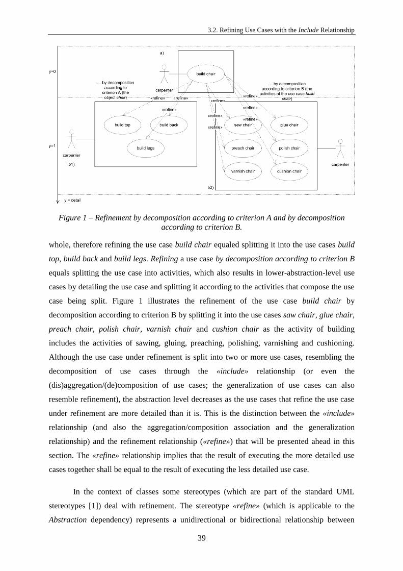
3.2. Refining Use Cases with the Include Relationship
39
Figure 1 – Refinement by decomposition according to criterion A and by decomposition
according to criterion B.
whole, therefore refining the use case build chair equaled splitting it into the use cases build
top, build back and build legs. Refining a use case by decomposition according to criterion B
equals splitting the use case into activities, which also results in lower-abstraction-level use
cases by detailing the use case and splitting it according to the activities that compose the use
case being split. Figure 1 illustrates the refinement of the use case build chair by
decomposition according to criterion B by splitting it into the use cases saw chair, glue chair,
preach chair, polish chair, varnish chair and cushion chair as the activity of building
includes the activities of sawing, gluing, preaching, polishing, varnishing and cushioning.
Although the use case under refinement is split into two or more use cases, resembling the
decomposition of use cases through the «include» relationship (or even the
(dis)aggregation/(de)composition of use cases; the generalization of use cases can also
resemble refinement), the abstraction level decreases as the use cases that refine the use case
under refinement are more detailed than it is. This is the distinction between the «include»
relationship (and also the aggregation/composition association and the generalization
relationship) and the refinement relationship («refine») that will be presented ahead in this
section. The «refine» relationship implies that the result of executing the more detailed use
cases together shall be equal to the result of executing the less detailed use case.
In the context of classes some stereotypes (which are part of the standard UML
stereotypes [1]) deal with refinement. The stereotype «refine» (which is applicable to the
Abstraction dependency) represents a unidirectional or bidirectional relationship between

Chapter 3: Transforming Use Case Models into Logical Architectures
40
diagram elements at different levels of abstraction (e.g. analysis and design levels). The
Abstraction dependency represents a relationship that relates two elements representing the
same concept at different levels of abstraction or from different viewpoints. It also represents
a dependency in which there is a mapping between the supplier and the client. A class at the
analysis level may map to more than one class at the design level, which means that a single
supplier element can have a set of client elements. This thesis does not recommend using the
Abstraction dependency to represent refinement of use cases because it can be bidirectional
(and refinement is unidirectional).
In the UML Superstucture [1] (in the context of use cases, particularly in the
description of the semantics) the «include» relationship is stated to be used for the purpose of
extracting the common part of the functionality of two or more use cases to a separate use
case to be included (or reused) by those two or more use cases. It may be the case that the
modeler wants to replace (in a lower abstraction level) a use case by two or more detailed use
cases. Figure 1 depicts such situation (1a is less detailed than 1b1 and than 1b2). In this case,
the result will be two use case diagrams, the later more detailed than the previous one. For
this argument this thesis considers that the use of the system represented by the use case in
Figure 1a represents the uses of the system that the use cases in Figure 1b1 and that those in
Figure 1b2 represent as well. The difference is that the use case in Figure 1a is less detailed
than the use cases in Figure 1b1 together and the use cases in Figure 1b2 together as well.
This thesis does not recommend using the «include» relationship to represent the lowering of
use cases’ abstraction level since it is not according to its semantics in the UML metamodel.
This thesis proposes an extension to the UML metamodel to make available a UML
relationship to be used in the context of use cases for representing their refinement. Figure 2
illustrates a new UML metaclass (the Refine metaclass) created to satisfy the need for
extension of the UML metamodel this thesis identified. As far as the unidirectional
association is concerned, the end named detail references the more detailed use case (the
refining use case) and the association means that one or more Refine relationships refer to one
(more detailed) use case. Regarding the aggregation, the end named refine references the
Refine relationships owned by the use case and the end named refinedCase references the use
case that was detailed (the refined use case) and owns the Refine relationship. The metamodel
shows that two or more Refine relationships are owned by one (refined) use case, and one
(refined) use case may be detailed and own two or more Refine relationships. Summarily a
refined use case shall be refined by more than one refining use case and a refining use case

3.2. Refining Use Cases with the Include Relationship
41
Figure 2 – The proposed extension to the UML metamodel for representing the refinement of
use cases.
context UseCase inv:
let refines : Set(Refine) = self.incomingRefine in
if refines->size() >= 2
then let includes : Integer = refines->iterate(nextElement : Refine; accumulator :
Integer = 0 | accumulator->nextElement.refinedCase.include->size()) in
refines->size() – 1 = includes
endif
Figure 3 – The multiple refines constraint.
context UseCase inv:
if UseCase.include->size() >= 1
and UseCase.refine->size() >= 1
then UseCase.include->excludesAll(UseCase.refine)
endif
Figure 4 – The coexistence constraint.
shall refine one or more refined use cases (more than one refined use case if the refined use
cases are connected through «include» relationships; see Figure 3 for an OCL constraint on
this). An OCL constraint (in Figure 4) was written for expressing the impossibility of having
two use cases connected by both an «include» relationship and a «refine» relationship since
the first does not imply increasing the detail level and the second does.
Figure 1 exemplifies the notation of the «refine» relationship. It is evident by the
figure that two use cases connected through a «refine» relationship are situated at different
levels of abstraction. For instance the use cases build top, build back and build legs (situated
at the detail level 1) are more detailed than the use case build chair (situated at the detail level
0). A «refine» relationship is represented the same way the «include» relationship is and from
the less detailed use case to the more detailed use case in order to evidence the lowering of
the abstraction level. The only difference is that the arrow is labeled with the keyword
«refine».

Chapter 3: Transforming Use Case Models into Logical Architectures
42
Figure 5 – The refinement process.
The Refinement Process
Figure 5 illustrates how the modeler shall go from the initial use case diagram (5a) to
the detailed use case diagrams (5c and 5d). It is possible to consider more than three detail
levels despite this thesis is exemplifying with three of them. The initial use case diagram (the
more abstract one or less detailed one) must be analyzed independently for each of its use
cases for simplicity reasons. Figure 5b shows how the partial use case diagram is elaborated
from the use case 1 of the use case diagram in Figure 5a. Two «include» relationships were
defined for that use case, which resulted in the use cases 4 and 5. The use cases 6 and 7 are a
refinement of the use case 5. That is why the use case 5 is connected to the use cases 6 and 7
through a «refine» relationship. The use case 4 may be refined by use cases situated at the
same level of abstraction as those in the use case diagram in Figure 5c but in a distinct
diagram. The «refine» relationship is established between elements from two use case

3.2. Refining Use Cases with the Include Relationship
43
Figure 6 – Possibilities for the refinement of both an including use case and an included use
case.
diagrams at different levels of detail (the partial use case diagram, the more abstract one, and
the 5c use case diagram, the more detailed one). At this point it can be concluded that the
«refine» relationship implies lowering the abstraction level (or increasing the detail level) as
well as when the abstraction level decreases a new use case diagram has to be ellaborated.
The refinement of the use case 7 (which gave origin to the use case diagram in Figure 5d) is
used to show that not only included use cases or use cases that do not own any «include»
relationship can be refined as exemplified in Figure 5. Including use cases can also be
refined. When refining an including use case the included use cases are likely to be refined as
well since their functionality is represented by the including use case as already explained in
this chapter. Figure 5 is also to depict the impossibility of having two use cases connected by
both an «include» relationship and a «refine» relationship.
Figure 6 depicts two possible cases for the refinement of both an including use case
and an included use case connected through an «include» relationship. The most adequate
modeling is the one in Figure 6a where the use case 3 refines two use cases (1 and 2) and is
not repeated as it is in Figure 6b. That is possible because the refined use cases are connected
through an «include» relationship, which implies that a complete use case is repeated in two
use case diagrams at the same level of abstraction (the use case diagram that refines the
including use case and the use case diagram that refines the included use case).

Chapter 3: Transforming Use Case Models into Logical Architectures
44
Use case name: Send Message Use case description: The mobile user writes the message in a text editor. The mobile user sends some different kinds of messages through the GoPhone. When writing the message, the mobile user activates letter combination (T9). The mobile user inserts objects into a message. The mobile user attaches objects to a message. The GoPhone connects to the network to send the message. In order for the GoPhone to show an acknowledgement to the mobile user (stating that the message was successfully sent), it receives an acknowledgement from the network. Upon request from the GoPhone, the mobile user chooses to save the
message into the sent messages folder.
Figure 7 – Non-stepwise textual description of the use case Send Message.
Use case name: Compose Message Use case description: The mobile user writes the message in a text editor. The mobile user sends some different kinds of messages through the GoPhone. When writing the message, the mobile user activates letter combination (T9). The mobile user
inserts objects into a message. The mobile user attaches objects to a message.
Figure 8 – Non-stepwise textual description of the use case Compose Message.
Use case name: Insert Object Use case description: The mobile user inserts objects into a message. The mobile user may receive notifications on the violation
of validation rules over the objects to be inserted into a message.
Figure 9 – Non-detailed non-stepwise textual description of the use case Insert Object.
Use case name: Insert Object Use case description: The mobile user selects the objects from a repository of objects (eventually with folders), which he can browse. Upon selection of the objects from the repository, they are displayed to the mobile user in the message area of the message editor. The mobile user may receive notifications on the violation of validation rules over the objects to be inserted into
a message. The violation of those rules prevents the display of the invalid objects to the mobile user.
Figure 10 – Detailed non-stepwise textual description of the use case Insert Object.
Use case name: Browse Repository Use case description: The mobile user selects the objects from a repository of objects (eventually with folders), which he can
browse.
Figure 11 – Non-stepwise textual description of the use case Browse Directory.
Use case name: Display Object in Message Area Use case description: Upon selection of the objects from the repository, they are displayed to the mobile user in the message area of the message editor. The mobile user may receive notifications on the violation of validation rules over the objects to be
inserted into a message. The violation of those rules prevents the display of the invalid objects to the mobile user.
Figure 12 – Non-stepwise textual description of the use case Display Object in Message
Area.
The GoPhone Case Study
The non-stepwise textual descriptions in figures 7 through 12 were elaborated based
on the functional requirements from the GoPhone. As previously stated in this chapter the
«include» relationships are defined based on the non-stepwise textual descriptions of use
cases. Figure 13 shows the graphical representation of the use cases textually described in
figures 7 through 12. It can be seen that the textual descriptions of the included use cases are
contained by the textual descriptions of the including use cases (e.g. the textual description of
the Compose Message use case is contained by the textual description of the Send Message
use case and the non-detailed textual description of the Insert Object use case is contained by
the textual description of the Compose Message use case). This is an evidence of how
«include» relationships imply decomposition but no detailing (of the including use cases’
textual descriptions). The «refine» relationships imply that the textual descriptions of the
refining use cases are more detailed than the textual descriptions of the refined use cases and

3.2. Refining Use Cases with the Include Relationship
45
Figure 13 – The use case diagrams of the Send Message functionality from the GoPhone.
also that for a single refined use case there is more than one refining use case (which means
that «refine» relationships imply decomposition besides detailing). For instance the textual
description of the Browse Directory use case is contained by the detailed textual description
of the Insert Object use case (note that this detailed textual description is not the description
corresponding to the Insert Object use case in the use case diagram, rather the non-detailed
textual description of the Insert Object use case is; the more detailed textual description was
only used as an intermediary/auxiliary means to get to the descriptions of the refining use
cases Browse Directory and Display Object in Message Area). This is evidence that the use
cases at the detail level 1 in the figure are more detailed than the use cases at the detail level 0
in the figure.
The sum of the functionality represented by the non-stepwise textual descriptions of
the included use cases shall be equal to the functionality represented by the non-stepwise
textual description of the including use case. In the use case diagram at the detail level 0 in
Figure 13 although the sum of the functionality represented by the non-stepwise textual
descriptions of the use cases included by the Send Message use case is equal to the
functionality represented by the non-stepwise textual description of the Send Message use
case, the actor Mobile User was not associated with the Send Message use case but it could
have been. This thesis did not associate the Mobile User with the Send Message use case

Chapter 3: Transforming Use Case Models into Logical Architectures
46
Figure 14 – The use case variability types.
because the purpose was to explicitly evidence the actor of each one of the included use cases
in particular since there are two actors involved in the Send Message use case (the Mobile
User and the Network). That is not what happens with the Compose Message use case as
there is only one actor involved in the use case.
Regarding the use case diagram at the detail level 1 in Figure 13 the refining use cases
are associated with an actor, which means that refining use cases have to be utilizations of the
system by themselves (all use cases shall have an association with the exterior of the system
they belong to whether they are including, included, refined or refining use cases, otherwise
this thesis would not be talking about use cases).
3.3. Modeling Variability with the Extend Relationship
Variability in Use Case Modeling
Figure 14 illustrates the variability types this thesis considers and proposes to be
applicable in the context of use cases. Use cases can be non-option or option. Non-option use
cases are present in all product line members. Option use cases can be present in one product
of the product line and not in another. It is not mandatory that option use cases are present in
all products of the product line. Non-variant use cases are use cases that are present in all
product line members but do not support variability. Variant use cases are use cases that are
present in all product line members as well as they are use cases that support variability. This
means that different products will support different alternatives for performing the same
functionality or that different products will support different specializations of the same
functionality. Later on during the modeling activity variant use cases are realized into
3.3. Modeling Variability with the Extend Relationship
47
alternatives or specializations respectively. Alternative use cases represent alternatives for
performing the same system’s use in mutually exclusive products or sets of products from the
product line. Specialization use cases represent a special kind of alternatives. A specialization
use case is a use case that represents the specialization of another use case. Specialization use
cases that specialize the same use case represent alternatives for performing the same
system’s use in mutually exclusive products or sets of products from the product line.
Specialization use cases that specialize the same use case indeed represent alternatives to
each other but they specialize a use case, which is not the case of alternative use cases.
Option, alternative and specialization use cases are the representation of the three variability
types that will be translated into stereotypes to be applicable to use cases. The use cases that
do not represent options and are not variant (neither later alternatives nor specializations) are
non-option and non-variant, and shall not be marked with any stereotype. Non-option and
option use cases are mutually exclusive as well as non-variant and variant use cases. Figure
14 represents the activity of classifying use cases with variability types: either non-option and
non-variant or option and non-variant or non-option and variant or option and variant. These
last two variability types can be realized into the alternative or the specialization variability
types (as already explained). The activity of classifying use cases with the variability types is
important for applying the corresponding stereotypes to the use cases (except for the non-
option and non-variant use cases, which shall not be marked with any stereotype). The
conditions of the decision nodes express the semantics of each one of the variability types.
This thesis would like to give emphasis to a particular variability type: the option and variant
variability type. This variability type is applicable to a use case that is not present in all
product line members but the different members in which it is present support different
alternatives for performing that use case’s functionality or different specializations of that use
case’s functionality. Option and non-variant use cases shall be marked as option use cases;
non-option and variant as variant use cases; and option and variant use cases as both option
and variant use cases.
Figure 15 depicts the use case diagram elaborated from the GoPhone concerning the
messaging domain and the highest abstraction level (these use cases are the less detailed this
chapter is presenting).
This thesis proposes an extension to the UML metamodel in order to formally provide
for both the concrete and abstract syntaxes to represent the three variability types that are to
be translated into stereotypes to be applicable to use cases. From now on this thesis either

Chapter 3: Transforming Use Case Models into Logical Architectures
48
Figure 15 – Use case diagram from the GoPhone case study (highest abstraction level).
uses the «extend» relationship without stereotypes or with one of the two stereotypes
applicable to this relationship from the proposed extension to the UML metamodel
(depending on whether this thesis is modeling alternatives or specializations). Using no
stereotypes on the «extend» relationship means that no variability is being modeled,
otherwise the stereotypes applicable to the «extend» relationship from the proposed extension
to the UML metamodel shall be used.
The «extend» Relationship
In order for use cases to be appropriate for product line modeling, they have to be
equipped with variability mechanisms. These variability mechanisms must allow determining
the locations in diagrams (in this case, use case diagrams) where variation will occur when
instantiating the product line.
The «extend» relationship allows modeling alternative and specialization use cases in
use case diagrams. Consider that an extending use case is a use case that extends another use
case and that an extended use case is a use case that is extended by other use cases. As any
other use case, an extending use case represents a given use of the system by a given actor or
actors.

3.3. Modeling Variability with the Extend Relationship
49
In the UML metamodel the extending use cases are considered to represent
supplementary behavioral increments that have to be inserted into the appropriate insertion
points between the extended use case’s fragments. These fragments refer to parts of the
textual descriptions of use cases. The position of this thesis is that both extending and
extended use cases represent supplementary behavioral increments since in the context of
product lines they represent functionality that is only essential for developing product lines
(both represent alternatives). In principle the functionality represented by the extended use
cases will be available for more advanced products in terms of functionality.
In the context of alternatives both extending and extended use cases represent
supplementary functionality (or supplementary behavioral increments) since both represent
alternatives, which are not essential for a product without variability to function. It shall be
noted that alternatives are no longer supplementary when product line members are
instantiated from the product line. Alternatives can be modeled with the generalization
relationship in use case diagrams, but this thesis recommends to model alternatives with the
«extend» relationship in order to evidence their supplementary character according to the
UML semantics (when supplementary is mentioned in this thesis, supplementary behavioral
increments from the UML semantics associated with the «extend» relationship are referred).
Therefore the concept of alternative is semantically supported by the «extend» relationship.
The «extend» relationship implies that alternatives are represented as binary and
unidirectional dependencies. The alternative relationship is binary and unidirectional because
the extending use case (just one or one from many) is an alternative to the extended use case.
The extended use case is modeled as the extended one in order to evidence that it shall be
present in products less robust in terms of functionality as opposite to all the others. A
situation in which there is more than one alternative to a specific use case shall be represented
with that specific use case as the extended use case and the other use cases as the extending
ones relatively to that specific use case (the «extend» relationships shall be marked with the
stereotype «alternative»). Situations with a high number of alternatives shall be modeled with
different diagrams that shall have the extended use case in common.
If the intention is to use differential specification, specializations shall be modeled
with the «extend» relationship in order to evidence their supplementary character according
to the UML semantics, otherwise they shall be modeled with the generalization relationship.
Differential specification of specializations means that specialization use cases represent
supplementary functionality regarding the use case they specialize, therefore a product

Chapter 3: Transforming Use Case Models into Logical Architectures
50
without variability does not require the specialization use cases to function. Not requiring the
specialization use cases implies the respective use case that is specialized is not required for a
product without variability to function as well. Besides that, a specialization use case is an
extending use case and the respective use case that is specialized is an extended use case,
which according to the position of this thesis means both represent supplementary
functionality as previously explained. It can be concluded that differential specification is
related to supplementary functionality from the UML «extend» relationship’s semantics. In
the approach of this thesis, differential specification is used, therefore a specialization is
represented as a relationship through a stereotype applicable to the «extend» relationship. A
«specialization» relationship is an «extend» relationship marked with the stereotype
«specialization».
Options represent functionality that is only essential for a product with variability to
function (when developing product lines), therefore options represent supplementary
behavioral increments. However this thesis does not recommend modeling options with the
«extend» relationship because if the stereotype was on the relationship, the relationship itself
would be optional and that is not the case (the use case is not optional with regards to any
other use case, rather it is optional by itself).
Options shall be modeled with a stereotype in use cases. The involvement of an
option use case (classified with the option and variant variability type) in either «extend» or
«include» relationships, or even in none of those does not imply the presence of that use case
in all product line members (which makes of it optional).
In principle an extending use case is a use case that extends another use case both in
the case of alternatives and in the case of specializations. In the case of specializations, this
thesis considers that there is no multiple inheritance, therefore it is impossible for an
extending use case to extend more than one use case. If there is more than one alternative use
case for the same functionality, one of those use cases shall be the alternative to all the others
and extended by them. That use case is the one to be present in the products less robust in
terms of functionality. The extended use case is not aware of the functionality described in
the extending use case.
As previously mentioned if the intention is not to use differential specification,
generalization relationships shall be used because specializations are complementary under
those circumstances. However it may be argued in a different way that the generalization

3.3. Modeling Variability with the Extend Relationship
51
Figure 16 – The specialization of the
variant use case Borrow Book with a
single actor.
Figure 17 – The specialization of the use
case Borrow Book with two different
actors.
Figure 18 – The specialization of the
variant use case Borrow Book with two
different actors.
Figure 19 – The specialization of the
variant use case Borrow Object.
relationship shall not be used to represent specializations in contexts of variability. Consider
the examples depicted in figures 16 through 19. The examples are an exception in terms of
the (GoPhone) case study that is used in this chapter. The figure shows that the use case
Borrow Book can be specialized into Borrow Book to Student and Borrow Book to Teacher. If
the actor is the same (the Librarian, who registers the borrowing), then the use cases that
specialize the Borrow Book use case are alternatives to borrowing a book as both can be
performed by the same actor. If the actor is not the same (the Student, in the case of the
Borrow Book to Student, and the Teacher, in the case of the Borrow Book to Teacher), then
the use cases that specialize the Borrow Book use case are not alternatives to borrowing a
book as both cannot be performed by the same actor (the same actor does not have an
alternative way of borrowing a book). Although the use case Borrow Book is connected to no
actor, it is a use case that is in fact connected to the actors of the use cases that specialize it
(Student and Teacher). If both of these actors were connected to the use case Borrow Book, it
would not be explicit which part of the use case they would perform (either the one related to
the book borrowing to student or the other related to the book borrowing to teacher). In this
case, in order for the generalization to be considered as variability, the actor of Borrow Book
has to be the Library User (connected to Borrow Book) specialized into the Student
(connected to Borrow Book to Student) and into the Teacher (connected to Borrow Book to
Teacher). Following the semantics of generalization in what actors in use case diagrams are

Chapter 3: Transforming Use Case Models into Logical Architectures
52
Figure 20 – The proposed extension to the UML metamodel (figure 16.2 from [1]) for
modeling variability in use case diagrams.
concerned, being Student and Teacher subtypes of Library User, they both interact with the
specific subuse case they are associated with as well as with the superuse case they are
associated with via the superactor. Contrarily to the case of Figure 17, in Figure 18 it is
explicitly known which part of the superuse case Borrow Book they perform (the Student
performs the one related to the book borrowing to student and the Teacher performs the other
related to the book borrowing to teacher). Another example: the use case Borrow Object can
be specialized into Borrow Book and Borrow CD. In this case, the actor can be the same for
all the use cases (the Student OR the Teacher). In order to support all the actors at the same
time (the Student AND the Teacher), the Library User has to be specialized into them (the
Student and the Teacher) and connected to the Borrow Object use case. This way the same
actor (the Library User) can borrow an object (a Book) or alternatively another (a CD).
Figure 20 depicts the extension this thesis proposes to the UML metamodel
concerning the «extend» relationship and use cases. This thesis adds the stereotypes
«alternative», «specialization» and «option» to the standard UML stereotypes in order to
distinguish the three variability types that were to be translated into stereotypes to be
applicable to use cases. This thesis has also added the stereotype «variant» to the standard
UML stereotypes in order to mark use cases at higher levels of abstraction before they are
realized into alternatives or specializations. A use case can include some use cases that are
not marked with «variant» since they are alternatives (involved in «alternative»
relationships), they are involved in «specialization» relationships or they are non-option and
non-variant (if not marked with any stereotype and not involved in «alternative» or
«specialization» relationships). For instance Send Message (Figure 15) is at the highest detail
level and it is marked with «variant». Some of the use cases it includes are not marked with
«variant» since they were realized as alternatives (involved in «alternative» relationships), or
3.3. Modeling Variability with the Extend Relationship
53
they are non-option and non-variant (if not marked with any stereotype and not involved in
«alternative» relationships). Use cases could have been marked with «variant» in the
approach of this thesis and related to variation points. Usually a variation point is associated
with one or more variants (from [42]). This thesis did not adopt variation points to avoid
additional graphical elements in use case diagrams, to avoid more complexity in use case
diagrams and to avoid reasoning about variability that shall be present in decision models.
This thesis proposes the stereotype «option» to be applicable to use cases that represent
options. «option» is for marking use cases that are not mandatory for all product line
members. It also proposes the stereotypes «alternative» and «specialization» to be applicable
to the «extend» relationship for modeling alternatives and specializations respectively.
Extending use cases involved in «alternative» relationships do not need to be marked with
the stereotype «alternative» to evidence them as alternatives since they do not make sense
without being involved in that kind of relationships (an alternative use case is always
alternative to another use case). The same happens with the stereotype «specialization» (a use
case involved in a specialization relationship always specializes another use case).
Regarding Figure 20 and the Extend metamodel element, as far as the unidirectional
association is concerned, the end named extendedCase references the use case that is being
extended (the extended use case) and the association means that many (zero or more)
«extend» relationships refer to one extended use case. Regarding the aggregation, the end
named extend references the «extend» relationships owned by the use case, and the end
named extension references the use case that represents the extension (the extending use case)
and owns the «extend» relationship. The metamodel means that one «extend» relationship is
owned by one extending use case. Summarily a use case can be extended by many use cases
and a use case can extend another use case. There can be zero or more alternatives
(«alternative» relationships) to a use case. There can also be zero or more specializations
(«specialization» relationships) for a use case. Although it can be argued that specializations
are only worth the effort when there are two or more specialization use cases, this thesis does
not want to take freedom away from the modeler.
It is important to distinguish alternatives from specializations in contexts of
variability. In the case of alternatives, the extending use case is an alternative to the extended
use case. In the case of specializations, the extending use cases are alternatives to each other.
Figure 21 shows the specialization of two alternative use cases from Figure 15: Insert Picture

Chapter 3: Transforming Use Case Models into Logical Architectures
54
Figure 21 – The specialization of Insert Picture and Insert Picture or Draft Text.
and Insert Picture or Draft Text. It is possible to transform alternatives into specializations
and the other way around. Again this thesis is not restrictive on this since it does not want to
take freedom away from the modeler. Insert Picture or Draft Text is an alternative to Insert
Picture because it extends the functionality represented by Insert Picture (which means that
in this case and in the context of product lines, it is an alternative to Insert Picture).
Variability in Use Case Modeling with Refinement
Use cases can be decomposed with or without detailing their non-stepwise textual
descriptions. Without detailing those descriptions this thesis proposes to represent the
decomposition of use cases in use case diagrams with the «include» relationship (e.g. the
decomposition of the Send Message use case from Figure 15). This decomposition suits the
purpose of e.g. (1) modeling later on an alternative to a part of the decomposed use case;
or (2) modeling a part of the decomposed use case that is an optional part (e.g. in Figure 15
Insert Picture is a part of Compose Message and has an alternative, which is Insert Picture or
Draft Text; in Figure 15 Activate Letter Combination is a part of Compose Message and
represents an option).
Figure 22 depicts use cases according to the perspectives of detail*variability to
illustrate in abstract terms the approach of this thesis to use case modeling with support for
variability. The detail perspective is intimately related to the activity of use case refinement.
In this sense use cases can be more detailed if they are refined. The variability perspective is
associated with the modeling of variability for product line support. The two perspectives
(detail and variability) were converted into axes of the illustrated space: y=detail and
z=variability. Each level of the z axis corresponds to a (parallel) plan, which means that this
thesis positions use cases in variability plans. Thus variability plans are plans that contain use

3.3. Modeling Variability with the Extend Relationship
55
Figure 22 – Use cases positioned according to the perspectives of detail*variability.
cases representing variability in the three different types translated into stereotypes to be
applicable to use cases. The plan z=0 contains none of these use cases that represent
variability.
The figure clarifies that the «refine» relationships imply increasing the detail level,
whereas the «extend» relationships do not imply increasing the detail level but rather
changing from one variability plan (z plan) to another. Extending use cases represent
alternative or specialization use cases, therefore they must be situated at the same level of
detail but in different variability plans (z plans). Variabilities do not imply adding detail to
the non-stepwise textual descriptions of the use cases like refinements do.
The figure shows the general case of the refinement of two use cases connected
through an «extend» relationship. The refinement of a use case stereotyped as «option» is not
relevant here, since it is not the case of an «extend» relationship connecting two use cases.
The figure evidences that the refinement of two use cases connected through an «extend»
relationship originates more detailed use cases organized in two packages that have also an
«extend» relationship connecting them. That is not always the case. It is possible to have two
use cases connected through a «specialization» relationship, which produces «specialization»
relationships connecting more detailed individual use cases (and not packages) in different
variability plans (an example of such case is in the next subsection).
The GoPhone Case Study
The non-stepwise textual descriptions in Figure 23 were elaborated based on the
functional requirements for the GoPhone. This thesis relies on non-stepwise textual
descriptions of use cases (the opposite of stepwise textual descriptions of use cases) to model

Chapter 3: Transforming Use Case Models into Logical Architectures
56
Use case name: {U 0.1} Send Message Use case description: The mobile user writes the message in a text editor. The GoPhone connects to the network to send the message. In order for the GoPhone to show an acknowledgement to the mobile user (stating that the message was successfully sent), it receives an acknowledgement from the network. Upon request from the GoPhone, the mobile user chooses to save the message into the sent messages folder. Alternatives:
The mobile user chooses the recipient’s contact. [Use cases’ name: {U 0.1.1e1} Choose Recipient’s Phone Number / {U 0.1.1e2} Choose Recipient’s Phone Number or E-mail Address]
The mobile user sends some different kinds of messages through the GoPhone. [Use cases’ name: {U 0.1.2.1e1} Select Basic or Extended Kind of Message / {U 0.1.2.1e2} Select Basic, Extended or E-mail Kind of Message]
The mobile user inserts objects into a message. [Use cases’ name: {U 0.1.2.3e1} Insert Picture / {U 0.1.2.3e2} Insert Picture or Draft Text]
The mobile user attaches objects to a message. [Use cases’ name: {U 0.1.2.4e1} Attach Business Card or Calendar Entry / {U 0.1.2.4e2} Attach File, Business Card, Calendar Entry or Sound]
The message is saved into the sent messages folder. [Use cases’ name: {U 0.1.4e1} Archive Message by Request / {U 0.1.4e2} Automatically Archive Message]
Specializations: - Options: When writing the message, the mobile user activates letter combination (T9). [Use case’s name: {U 0.1.2.2e1} Activate Letter Combination]
Use case name: {U 0.1.2} Compose Message Use case description: The mobile user writes the message in a text editor. Alternatives:
The mobile user sends some different kinds of messages through the GoPhone. [Use cases’ name: {U 0.1.2.1e1} Select Basic or Extended Kind of Message / {U 0.1.2.1e2} Select Basic, Extended or E-mail Kind of Message]
The mobile user inserts objects into a message. [Use cases’ name: {U 0.1.2.3e1} Insert Picture / {U 0.1.2.3e2} Insert Picture or Draft Text]
The mobile user attaches objects to a message. [Use cases’ name: {U 0.1.2.4e1} Attach Business Card or Calendar Entry / {U 0.1.2.4e2} Attach File, Business Card, Calendar Entry or Sound]
Specializations: - Options: When writing the message, the mobile user activates letter combination (T9). [Use case’s name: {U 0.1.2.2e1} Activate Letter Combination]
Use case name: {U 0.1.4e1} Archive Message by Request Use case description: Upon request from the GoPhone, the mobile user chooses to save the message into the sent messages folder. Alternatives: The GoPhone automatically archives the message [Use cases’ name: {U 0.1.4e2} Automatically Archive Message] Specializations: -
Options: -
Use case name: {U 0.1.4e2} Automatically Archive Message Use case description: The GoPhone saves the message into the sent messages folder and notifies the mobile user on the successful message saving into that folder. Alternatives: - Specializations: -
Options: -
Use case name: {U 0.1.2.3e1} Insert Picture Use case description: The mobile user inserts pictures into the message. The mobile user may receive notifications on the violation of validation rules over the pictures to be inserted into the message. Alternatives: The mobile user inserts pictures or draft texts into the message. [Use cases’ name: {U 0.1.2.3e2} Insert Picture or Draft Text] Specializations: -
Options: -
Use case name: {U 0.1.2.3e2} Insert Picture or Draft Text Use case description: The mobile user inserts pictures and/or draft texts into the message. The mobile user may receive notifications on the violation of validation rules over the pictures and/or the draft texts to be inserted into the message. Alternatives: - Specializations: -
Options: -
Figure 23 – Non-stepwise textual descriptions from the GoPhone use case Send Message and
some of its related use cases.
variability in use case diagrams. Stepwise textual descriptions are structured textual
descriptions in natural language that provide for a stepwise view of the use case as a sequence
of steps, alert for the decisions that have to be made by the user and evidence the notion of
use case actions temporarily dependent on each other. Stepwise descriptions shall be treated
after modeling the use cases. (Cockburn presents in [22] different forms of writing textual
descriptions for use cases.)
In the context of the «extend» relationship the UML Superstructure states that an
extending use case consists of one or more behavior fragment descriptions to be inserted into

3.3. Modeling Variability with the Extend Relationship
57
the appropriate spots of the extended use case. This means that the functionality of the
extending use case is not described in the extended use case. The extended use case is not
aware of the functionality described in the extending use case (e.g. as can be seen from
Figure 23 the functionality of the Automatically Archive Message use case is not described in
the Archive Message by Request use case, as well as the functionality of Insert Picture or
Draft Text is not described in Insert Picture, although they are very similar). This thesis
would like to note that the statement of the UML Superstructure mentioning that the
execution of an extended use case and its extending use cases is only one is not valid in the
context of product lines, particularly for alternatives. As Figure 24 depicts, the use case
Automatically Archive Message is an alternative to the use case Archive Message by Request
(they are connected through a kind of «extend» relationship, tagged with the stereotype
«alternative» in order to evidence that the use case Automatically Archive Message is an
alternative to the use case Archive Message by Request). It must be noticed that Archive
Message by Request is an (included) use case included by the including use case Send
Message, which means that the functionality of the use case Archive Message by Request is
described in the Send Message use case. For this reason this thesis could have extended the
Send Message use case with the use case Automatically Archive Message, but then it would
not be evidencing to which part of the functionality of the Send Message use case the use
case Automatically Archive Message is an alternative to. Figure 24 also depicts that the
Browse Directory of Pictures use case is a specialization of the use case Browse Repository
(they are connected through another kind of «extend» relationship, tagged with the stereotype
«specialization» in order to evidence that the use case Browse Directory of Pictures is a
specialization of the use case Browse Repository). Option use cases shall be marked with the
stereotype «option» (e.g. as Figure 24 evidences for the Activate Letter Combination use
case).
Figure 24 shows some examples of variability modeled in use cases. The use cases in
grey are those that do not represent variability. No borders containing use cases in the
variability plans with z>0 were drawn because those borders are going to be needed during
product derivation (or the generation of product models from the product line model, which is
out of the scope of this thesis). All the use cases in the diagrams in this section have the
values they take for both the perspectives of variability (z) and detail (y). These are not
tagged values, rather just a help for the reader to visualize the use cases in the right place.
Figure 24 seems complex but it ought to be noticed that the figure contains two diagrams and
that the extensions to the use cases in the diagrams could have been modeled in different

Chapter 3: Transforming Use Case Models into Logical Architectures
58
Figure 24 – Use case diagram from the GoPhone case study (two detail levels).

3.3. Modeling Variability with the Extend Relationship
59
Figure 25 – An example of refinement of the specialization type of variability from the
GoPhone.
artifacts. By stating this this thesis states that the diagram in Figure 24 could have been
separated in some diagrams. Nevertheless this thesis cannot escape variability in its different
types for the reasons already explained.
Figure 25 shows the refinement of the specialization type of variability. The figure
shows that both the use case that is specialized (the Browse Repository use case) and the
specialization use cases (the Browse Directory and Browse List use cases) were refined.
Some use cases that refine the specialization use cases are specializations of the use cases that
refine the use case that is specialized (e.g. the View Picture use case is a specialization of the
View Object use case). The use case Open Folder represents functionality that is not common
to both specialization use cases since it is only applicable to one of the objects the
specialization use cases refer to (the Directory of Pictures). Having in mind that
specializations are a special kind of alternatives, specialization use cases are alternatives to
each other. Figure 25 illustrates that the use cases that refine the specialization use cases are
alternatives to each other as packages.
Figure 26 depicts that the use cases that refine two use cases connected through an
«alternative» relationship are alternatives to each other as packages.

Chapter 3: Transforming Use Case Models into Logical Architectures
60
Figure 26 – An example of refinement of alternative variability from the GoPhone.
3.4. The 4SRS Method with Variability Support
Synopsis of the 4SRS Method
The 4SRS is a UML modeling method for obtaining system functional requirements from
user functional requirements. Use cases model user functional requirements and logical
architectures model system functional requirements. Use cases are problem-related,
technology-independent and dealt with during the analysis of software. Logical architectures
are solution-related, technology-independent and dealt with in the beginning of the design of
software. The 4SRS is a transition method according to previous statements in this thesis.
Shortly the 4SRS method is composed of the following steps: (1) Component Creation,
to create three kinds of components for each use case, based on the MVC (an interface
component, a control component and a data component; other kinds of components could be
created, so this is not a limitation of the method, rather an architectural decision);
(2) Component Elimination, to remove redundant requirements and to find missing
requirements (this step is vital in order to validate the components blindly created in the
previous step and it includes eliminating the components whose requirements are already
represented by other components; the finding of missing requirements means that
components were inadequately eliminated or use cases are missing); (3) Component
Packaging and Aggregation, to semantically group components in packages;
and (4) Component Association, to define associations of components with each other in the
component diagram.

3.4. The 4SRS Method with Variability Support
61
In the past the 4SRS method was extended to support tabular transformations in the
execution of its steps as well as some filtering and collapsing techniques to enable the
refinement of logical architectures. After that the method was extended to support the
modeling of logical architectures with variability support, which added the notion of
variability to it [29]. The work in this section is both the conjunction and the prosecution of
these previous works since it formalizes the filtering and collapsing as an intermediate step as
well as it formalizes the transformation from components to use cases in order to finish
preparing the recursive execution of the 4SRS method. The work of this thesis also
contemplates the formalization of use case refinement and the systematization of use case
variability modeling undertaken in this thesis. The formalization of use case refinement is
relevant for the preparation of the recursive execution of the 4SRS method. The
systematization of use case variability modeling is relevant for modeling use cases with
variability support, for determining the use cases that will be the input for the method’s
execution (recursive or not) and has implications when executing the method itself.
The scale problem mentioned in section 2.1 is the reason for the 4SRS method to have
included a technique to refine logical architectures. Handling a high number of use cases with
the method implies a high number of resulting components and a consequent high number of
possibilities for partitioning functionality into logical clusters. A high number of components
in the component diagram that comes out of executing the 4SRS method imposes a greater
amount of effort into some of method’s steps. Step 2 involves eliminating the semantical
redundancy of components. The more components, the more the probability of having
components representing the same functionality as others, which complicates the task of
comparing one to another. Step 4 becomes complex when there is a high number of
components to compare with each other in order to guarantee that they can or cannot be
connected since the possibility of associations to be established between components
increases. The high number of possibilities to partition functionality implies a greater amount
of effort into the execution of step 3. Comparing components to form packages of
components becomes hard.
The modeling of logical architectures with variability support (see [62] for an
example of a logical architecture’s representation through models) may be conducted with
specific instruments tailored to explicitly expose the variability of the product line like the
4SRS method with its extension to variability support. Architectural refinement is the
approach the 4SRS method takes to increment a primary logical architecture with detail (by

Chapter 3: Transforming Use Case Models into Logical Architectures
62
Figure 27 – Schematic representation of the recursive execution of the 4SRS method.
primary it is meant the architecture that is going to be detailed). In the context of this thesis,
recursion is the ability of the modeling method to be executed over parts of the output artifact
of a preceding execution after transformed into the input artifact for the current execution.
As depicted in Figure 27 the 4SRS method may be applied recursively, in several executions.
In the context of each one of those executions various iterations can be performed. Although
there is no stopping rule for iterating over the same use case diagram, it shall be performed
until the results obtained generate a logical architecture that does not benefit from additional
iterations in terms of the elimination of redundant requirements, the finding of missing
requirements and the increasing of the logical architecture’s cohesion. There cannot be
components isolated from the rest of the architecture when the global architecture is
composed from the various logical architectures generated by the different executions. In the
case of refinement (by recursion), when one of the executions is considered to be finished by
the modeler, the output of that execution’s last iteration (a component diagram) is going to
originate the input of a subsequent execution’s first iteration (a use case diagram). The task
flow of the new execution is exactly the same as the task flow of the preceding one. Again, in
the case of refinement (by recursion), the logical architectures produced by the various
executions are situated in lower levels of abstraction and cover less functionality than the
logical architectures they refined.
Considering architectural refinement, the sequence of steps for the 4SRS method is
the following: (1) Component Creation; (2) Component Elimination; (3) Component Packaging
and Nesting; (4) Component Association; (4+1) Filtering and Collapsing; and (4+2) From

3.4. The 4SRS Method with Variability Support
63
Components to Use Cases. The first four steps are the original steps and the other ones are
what this thesis calls the intermediate steps, which are performed in between executions of
the 4SRS method.
Step 2 is composed of seven microsteps. Microstep 2.i (Use Case Classification) is
about determining the kinds of components that will originate from each use case according
to the eight possible combinations. According to this classification, microstep 2.ii (Local
Elimination) is about eliminating the components blindly created in step 1 by analyzing the
textual description of the use cases and deciding on whether those components make sense in
the problem domain. Microstep 2.iii (Component Naming) is about naming the components
that were not eliminated in the previous microstep. Microstep 2.iv (Component Description)
is about textually describing the components named in the previous microstep, based on the
textual descriptions of the use cases they originated from, on nonfunctional requirements and
on design decisions. Microstep 2.v (Component Representation) is about determining
whether some components represent both their own system requirements and others’.
Microstep 2.vi (Global Elimination) is about eliminating the components whose requirements
are already represented by other components (elimination of functional redundancy). Finally,
microstep 2.vii (Component Renaming) is about renaming the components that were not
eliminated in the previous microstep and that represent additional components.
Generation of Logical Architectures with Variability Support
As already mentioned in this chapter, this thesis formalizes the techniques of filtering
and collapsing as well as the transformation from components to use cases as intermediate
steps of the 4SRS method to support the refinement of logical architectures. The following is
the new sequence of steps for the 4SRS method: (1) Component Creation; (2) Component
Elimination; (3) Component Packaging and Aggregation; (4) Component Association;
(4+1) Filtering and Collapsing; and (4+2) From Components to Use Cases. The first four steps
are the original steps and the other ones are what this thesis calls the intermediate steps,
which are performed in between executions of the 4SRS method.
As also already mentioned in this chapter, the systematization of use case variability
modeling is relevant for modeling use cases with variability support, for determining the use
cases that will be the input for the method’s execution and has implications when executing
the method itself. The remainder of this section discusses these three topics.

Chapter 3: Transforming Use Case Models into Logical Architectures
64
Modeling use cases with variability support implies some considerations related to the
variability types and the extension to the UML metamodel proposed in section 3.3. As any
other use case, use cases involved in alternative relationships, in specialization relationships
and those that stand for options represent a given use of the system by a given actor or actors.
Next the particularities of modeling alternative relationships, specialization relationships and
use cases that stand for options are going to be discussed. Since this thesis considers that the
«extend» relationship is adequate for modeling alternatives and specializations, and a
stereotype applicable to use cases for modeling options, it is important to discuss the
«extend» relationship thoroughly.
In the case of alternatives, a use case can extend another use case that is included by
two other use cases. It could be argued that the extending use case is an alternative to those
two other use cases but this is not the most accurate argument since the extending use case is
only alternative to a part of those two other use cases (a part that they share).
Consider that an extending use case is a use case that extends another use case and
that an extended use case is a use case that is extended by other use cases. In the context of
the «extend» relationship, extending use cases and extended use cases represent
supplementary functionality. In the context of product lines this means that they represent
functionality that is only essential for developing product lines.
Specializations can be modeled with the generalization relationship in use case
diagrams but as specialization use cases represent a special kind of alternatives, this thesis
recommends to model specializations with the «extend» relationship.
The relationship is optional if the use case is optional and not optional if the use case
is not optional (the relationship shall not exist for the products in which the use case shall not
exist as well). Furthermore the use case is not optional with regards to any other use case.
Rather it is optional by itself. Options shall be modeled with a stereotype in the use cases.
The stereotype is applicable to use cases independently of their involvement in either
«extend» or «include» relationships. As previously stated in this chapter, a use case classified
with the option and variant variability type (which corresponds to marking that use case with
the stereotypes «option» and «variant», or just «option» if the use case is an alternative use
case or a specialization use case) is not present in all product line members but the different
members in which it is present support different alternatives for performing that use case’s
functionality or different specializations of that use case’s functionality.

3.4. The 4SRS Method with Variability Support
65
Consider that a use case is shared by two use cases that include it. One of those two
use cases is non-option and the other one is option. The use case that is included is non-
option or option? The answer is non-option. The use case is going to be present in the product
line members in which the non-option use case is going to be present and is also going to be
present in the product line members in which the option use case is going to be present. This
means that the use case is going to be present in all product line members. If the stereotype
«option» is on use cases rather than on relationships, both the situation just described is
solved as well as the situation of a use case that is not included by any other use case.
This thesis approached option use cases from the perspective of the product line but it
could have approached them from the perspective of the members of the product line. This
thesis considers that variability no longer exists when moving from compile-time (during
which the work is around a product line) to runtime (during which the work is around
products from that product line). This thesis considers that after a build the work is around
binaries that are products from the product line that can only be changed during setup or post-
setup (runtime). Therefore at this point in time a use case is in a product and not in another if
it is in the binary of a product and not in the binary of another. However this thesis
acknowledges that variability exists at the level of product line members if use cases are
present in product line members after instantiation from the product line but during setup or
post-setup the use case is no longer available for the respective actor(s).
Determining the use cases that will be the input for the execution of the 4SRS method
depends on the support for variability in use case modeling. The 4SRS method shall only
consider leaf use cases as input. Figure 15 has the leaf use cases for the first execution of the
4SRS method highlighted in grey (in what concerns the messaging domain of the GoPhone
case study). Without variability support leaf use cases are the more detailed ones. With
variability support things change. This thesis proposes the following rules to be applied to the
determination of leaf use cases when variability is supported. Alternative use cases are leaf
use cases (they are involved in «alternative» relationships). Specialization use cases are leaf
use cases as well as the use case they are a specialization of (specialization use cases are
specializations of another use case). Option use cases are leaf use cases. This thesis has
discarded the possibility of using the «include» relationship to turn only a part of the
including use case public to be included by other use cases because that would not guarantee
the coherence of the use case diagram to generate logical architectures. Including use cases
are not leaf use cases (with or without variability support). If this thesis allowed including use

Chapter 3: Transforming Use Case Models into Logical Architectures
66
cases to include only one use case, then the included use cases (in this case, only one) would
not represent the totality of the functionality of the including use case and consequently the
logical architecture would not be coherent with the user requirements (some would be
missing in the architecture).
The execution of the 4SRS method has some implications when use cases are
modeled with variability support. This thesis proposes to extend step 2 of the 4SRS method
with a rule for the representation of alternatives and specializations. It is required that
interface components originated from alternative and specialization use cases (together with
the interface components originated from the use cases they specialize) are not represented by
any other component, otherwise the essence of a logical architecture with variability support
would be lost: the representation of commonalities (shared, reusable components) and
variabilities (instance-specific components) among the product members [70]. This thesis
also proposes to extend step 4 of the 4SRS method with a rule for the association of
components originated from specialization use cases and the use cases they specialize. The
components originated from specialization use cases shall be associated with those originated
from the use cases they specialize.
The presence of alternatives and specializations in use case diagrams has some
impacts on the execution of the 4SRS method. Due to the proposed extension of step 2 with a
rule for the representation of alternatives and specializations, the presence of alternatives and
specializations has impacts on that step regarding the global elimination of components. The
global elimination is about eliminating the components whose system requirements are
already represented by other components. It is required that interface components originated
from alternative and specialization use cases (together with the interface components
originated from the use cases they specialize) are not represented by any other component,
which implies they cannot be globally eliminated. Interface components originated from
option use cases cannot be represented by any other component.
Finally by executing the 4SRS method over the leaf use cases from Figure 15, the
component diagram in Figure 28 was obtained (apart from the crosses and the grey area,
which will be explained in the next subsection). The associations between actors and
components are usually defined based on the descriptions of components elaborated during
the execution of the 4SRS method (this thesis always tries to mention the actors in the
description of interface components). But this is not mandatory. The traceability between use
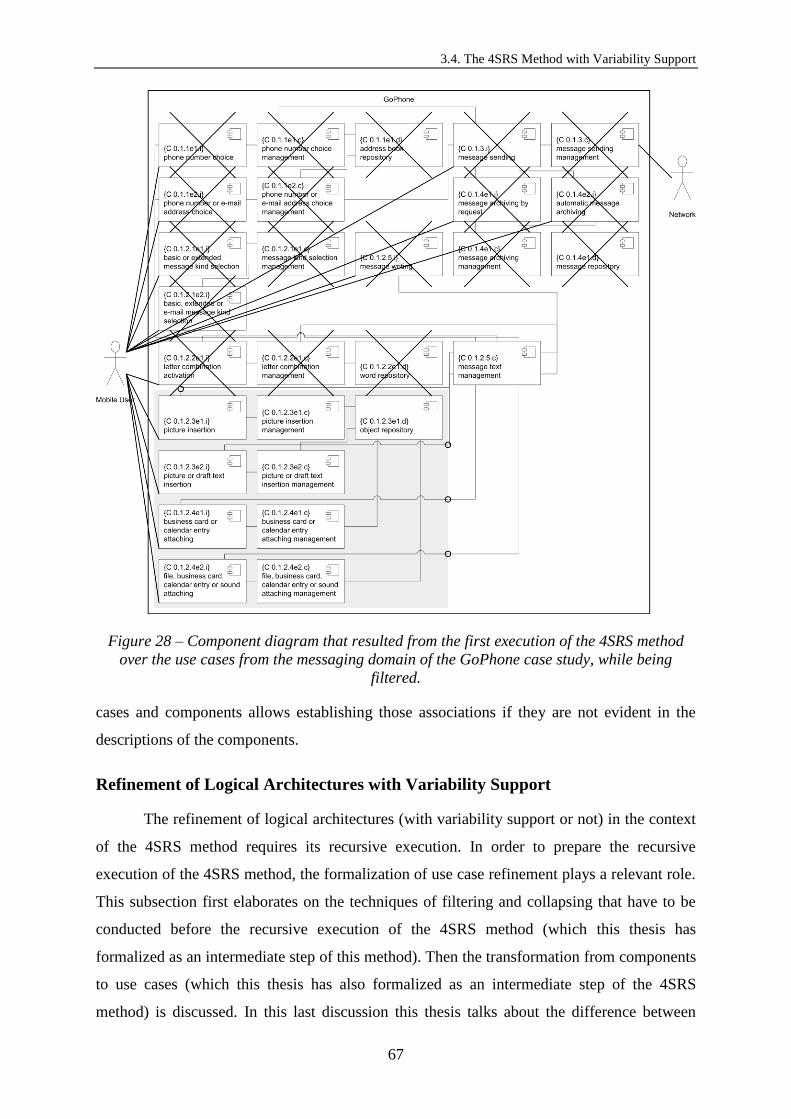
3.4. The 4SRS Method with Variability Support
67
Figure 28 – Component diagram that resulted from the first execution of the 4SRS method
over the use cases from the messaging domain of the GoPhone case study, while being
filtered.
cases and components allows establishing those associations if they are not evident in the
descriptions of the components.
Refinement of Logical Architectures with Variability Support
The refinement of logical architectures (with variability support or not) in the context
of the 4SRS method requires its recursive execution. In order to prepare the recursive
execution of the 4SRS method, the formalization of use case refinement plays a relevant role.
This subsection first elaborates on the techniques of filtering and collapsing that have to be
conducted before the recursive execution of the 4SRS method (which this thesis has
formalized as an intermediate step of this method). Then the transformation from components
to use cases (which this thesis has also formalized as an intermediate step of the 4SRS
method) is discussed. In this last discussion this thesis talks about the difference between

Chapter 3: Transforming Use Case Models into Logical Architectures
68
decomposing use cases with and without detailing them, and it uses the «include» UML
relationship to model the decomposition of use cases without detailing them and a UML
relationship (the «refine» relationship) to model the decomposition of use cases with their
detailing.
Filtering and Collapsing
This thesis uses techniques of filtering and collapsing in between executions of the
4SRS method. The filtering consists of considering some components as the subsystem for
refinement and discarding those that are not associated with them. The collapsing consists of
hiding the details of the subsystem whose components are going to be refined. Later on those
components are replaced inside the limits of the subsystem’s border by others of lower
abstraction level.
This thesis has formalized the filtering and collapsing as an intermediate step of the
4SRS method: 4+1 (Filtering and Collapsing). This step produces three artifacts: (a) a
component diagram while being filtered; (b) a filtered component diagram; and (c) a filtered
and collapsed component diagram.
Figure 28 is the component diagram while being filtered (concerning the GoPhone’s
messaging domain). The components with a cross are those that are not associated with the
components from the subsystem to refine, which are the ones from the grey area in the
diagram. There is only one component left ({C 0.1.2.5.c} message text management) and that
is the only one associated with the subsystem besides the Mobile User actor.
Figure 29 is the filtered component diagram (concerning the object insertion and
object attaching functionalities from the GoPhone’s messaging domain). It only contains the
components from the subsystem to refine, the only component that is associated with them
and the only actor that is also associated with them.
Figure 30 is the filtered and collapsed component diagram (concerning the object
insertion and object attaching functionalities from the GoPhone’s messaging domain). It is an
evolution of the filtered component diagram. It presents a subsystem in place of the
components that will be replaced by refined ones. The associations between the component
{C 0.1.2.5.c} message text management and those components were removed and replaced by
four interfaces, one for each of those associations. The components that will be placed inside

3.4. The 4SRS Method with Variability Support
69
Figure 29 – Filtered component diagram with regards to the object insertion and object
attaching functionalities of the Send Message use case from the GoPhone case study.
Figure 30 – Filtered and collapsed diagram for object insertion and attaching functionalities
from the GoPhone’s messaging domain.
the borders of the subsystem (the more detailed components that will be obtained from the
recursive execution of the 4SRS method) will have to comply with those interfaces.
Deriving Use Cases from Components
The intermediate step 4+2 (From Components to Use Cases) of the 4SRS method is
composed of two intermediate substeps: (4+2.i) Deriving Use Cases from Components and
(4+2.ii) Detailing Use Cases. The goal of intermediate substep 4+2.i (Deriving Use Cases from
Components) is to derive the use cases to hand out as input for the succeeding recursive
execution of the 4SRS method from the components to refine. The goal of intermediate
substep 4+2.ii (Detailing Use Cases) is to refine those use cases. The use case diagram at the
detail level (y) 0 in Figure 31 depicts the use cases based on the descriptions of the
components that will be refined. Those descriptions were elaborated during the execution of

Chapter 3: Transforming Use Case Models into Logical Architectures
70
Figure 31 – Use case diagram for the first recursive execution of the 4SRS method over the
GoPhone’s messaging domain.
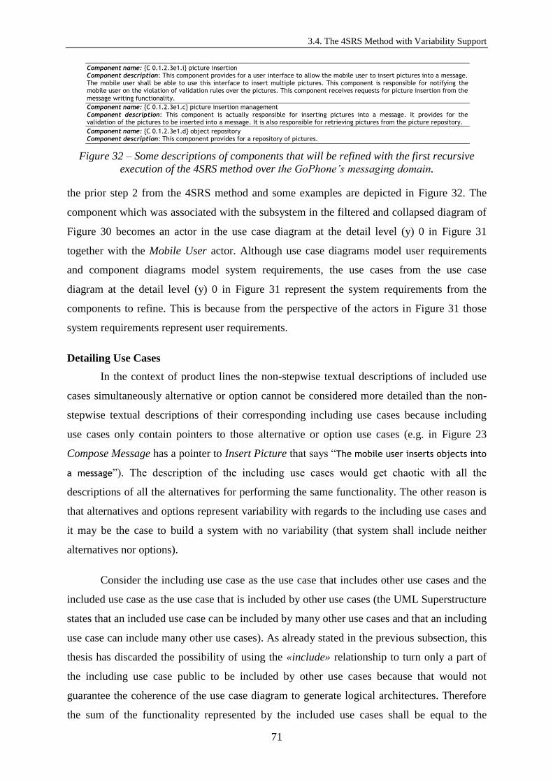
3.4. The 4SRS Method with Variability Support
71
Component name: {C 0.1.2.3e1.i} picture insertion Component description: This component provides for a user interface to allow the mobile user to insert pictures into a message. The mobile user shall be able to use this interface to insert multiple pictures. This component is responsible for notifying the mobile user on the violation of validation rules over the pictures. This component receives requests for picture insertion from the
message writing functionality.
Component name: {C 0.1.2.3e1.c} picture insertion management Component description: This component is actually responsible for inserting pictures into a message. It provides for the validation of the pictures to be inserted into a message. It is also responsible for retrieving pictures from the picture repository.
Component name: {C 0.1.2.3e1.d} object repository Component description: This component provides for a repository of pictures.
Figure 32 – Some descriptions of components that will be refined with the first recursive
execution of the 4SRS method over the GoPhone’s messaging domain.
the prior step 2 from the 4SRS method and some examples are depicted in Figure 32. The
component which was associated with the subsystem in the filtered and collapsed diagram of
Figure 30 becomes an actor in the use case diagram at the detail level (y) 0 in Figure 31
together with the Mobile User actor. Although use case diagrams model user requirements
and component diagrams model system requirements, the use cases from the use case
diagram at the detail level (y) 0 in Figure 31 represent the system requirements from the
components to refine. This is because from the perspective of the actors in Figure 31 those
system requirements represent user requirements.
Detailing Use Cases
In the context of product lines the non-stepwise textual descriptions of included use
cases simultaneously alternative or option cannot be considered more detailed than the non-
stepwise textual descriptions of their corresponding including use cases because including
use cases only contain pointers to those alternative or option use cases (e.g. in Figure 23
Compose Message has a pointer to Insert Picture that says “The mobile user inserts objects into
a message”). The description of the including use cases would get chaotic with all the
descriptions of all the alternatives for performing the same functionality. The other reason is
that alternatives and options represent variability with regards to the including use cases and
it may be the case to build a system with no variability (that system shall include neither
alternatives nor options).
Consider the including use case as the use case that includes other use cases and the
included use case as the use case that is included by other use cases (the UML Superstructure
states that an included use case can be included by many other use cases and that an including
use case can include many other use cases). As already stated in the previous subsection, this
thesis has discarded the possibility of using the «include» relationship to turn only a part of
the including use case public to be included by other use cases because that would not
guarantee the coherence of the use case diagram to generate logical architectures. Therefore
the sum of the functionality represented by the included use cases shall be equal to the
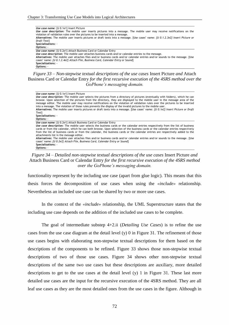
Chapter 3: Transforming Use Case Models into Logical Architectures
72
Use case name: {U 0.1e1} Insert Picture Use case description: The mobile user inserts pictures into a message. The mobile user may receive notifications on the violation of validation rules over the pictures to be inserted into a message. Alternatives: The mobile user inserts pictures or draft texts into a message. [Use cases’ name: {U 0.1.2.3e2} Insert Picture or Draft Text] Specializations: -
Options: -
Use case name: {U 0.2e1} Attach Business Card or Calendar Entry Use case description: The mobile user attaches business cards and/or calendar entries to the message. Alternatives: The mobile user attaches files and/or business cards and/or calendar entries and/or sounds to the message. [Use cases’ name: {U 0.1.2.4e2} Attach File, Business Card, Calendar Entry or Sound] Specializations: -
Options: -
Figure 33 – Non-stepwise textual descriptions of the use cases Insert Picture and Attach
Business Card or Calendar Entry for the first recursive execution of the 4SRS method over the
GoPhone’s messaging domain.
Use case name: {U 0.1e1} Insert Picture Use case description: The mobile user selects the pictures from a directory of pictures (eventually with folders), which he can browse. Upon selection of the pictures from the directory, they are displayed to the mobile user in the message area of the message editor. The mobile user may receive notifications on the violation of validation rules over the pictures to be inserted into a message. The violation of those rules prevents the display of the invalid pictures to the mobile user. Alternatives: The mobile user inserts pictures or draft texts into a message. [Use cases’ name: {U 0.1e2} Insert Picture or Draft Text] Specializations: -
Options: -
Use case name: {U 0.2e1} Attach Business Card or Calendar Entry Use case description: The mobile user selects the business cards or the calendar entries respectively from the list of business cards or from the calendar, which he can both browse. Upon selection of the business cards or the calendar entries respectively from the list of business cards or from the calendar, the business cards or the calendar entries are respectively added to the attachments list in the message editor. Alternatives: The mobile user attaches files and/or business cards and/or calendar entries and/or sounds to the message. [Use cases’ name: {U 0.2e2} Attach File, Business Card, Calendar Entry or Sound] Specializations: -
Options: -
Figure 34 – Detailed non-stepwise textual descriptions of the use cases Insert Picture and
Attach Business Card or Calendar Entry for the first recursive execution of the 4SRS method
over the GoPhone’s messaging domain.
functionality represent by the including use case (apart from glue logic). This means that this
thesis forces the decomposition of use cases when using the «include» relationship.
Nevertheless an included use case can be shared by two or more use cases.
In the context of the «include» relationship, the UML Superstructure states that the
including use case depends on the addition of the included use cases to be complete.
The goal of intermediate substep 4+2.ii (Detailing Use Cases) is to refine the use
cases from the use case diagram at the detail level (y) 0 in Figure 31. The refinement of those
use cases begins with elaborating non-stepwise textual descriptions for them based on the
descriptions of the components to be refined. Figure 33 shows those non-stepwise textual
descriptions of two of those use cases. Figure 34 shows other non-stepwise textual
descriptions of the same two use cases but these descriptions are auxiliary, more detailed
descriptions to get to the use cases at the detail level (y) 1 in Figure 31. These last more
detailed use cases are the input for the recursive execution of the 4SRS method. They are all
leaf use cases as they are the most detailed ones from the use cases in the figure. Although in

3.5. Conclusions
73
Figure 31 only two detail levels were considered, that is not a rule (this thesis could have
considered more detail levels if more detailing was concluded to be needed).
The Recursive Execution of the 4SRS Method
The goal of the recursive execution of the 4SRS method is to apply the method after
one or more of its executions have occurred beforehand. This process is about applying the
tabular transformations the 4SRS method is composed of to the target use cases (as already
explained in [6]). The result will be a list of components that shall be associated with each
other. The associations of components with each other are determined during the execution of
the 4SRS method. The definition of these associations is not necessarily based on the
descriptions of the components. This thesis tries always mentioning the interaction of
components with each other in their descriptions.
The resulting artifact from the recursive execution of the 4SRS method to a subsystem
of the GoPhone case study (concerning the object insertion and attaching functionalities from
the messaging domain) is the component diagram in Figure 35. This diagram has then to be
integrated into the logical architecture the preceding execution of the 4SRS method
originated to provide for a global logical architecture.
The integration is possible because the components in Figure 35 provide for the
interfaces required by the component from Figure 30.
3.5. Conclusions
This chapter elaborated on how the UML does not support refinement of use cases at
the moment and how it can be extended in order to support that formally. As a result this
thesis proposed to extend the UML metamodel with a new kind of relationship in the context
of use cases (the «refine» relationship). The support of use case refinement is pertinent in
large software systems development in order to deliver less complex modeling artifacts to the
teams implementing those systems. Use cases shall be delivered to the different teams with
responsibility for further designing and implementing the different sets of functionalities (a
single team is not expected to develop the whole system). According to what was clarified in
this chapter, the «include» relationship is not appropriate to model the refinement of use
cases since the refinement activity implies lowering the abstraction level of use cases
(particularly of their non-stepwise textual descriptions). Despite this, the «include»
relationship shall not be discarded and shall live along with the «refine» relationship as this

Chapter 3: Transforming Use Case Models into Logical Architectures
74
Figure 35 – Component diagram resulting from the first recursive execution of the 4SRS
method over the GoPhone’s messaging domain.
chapter elucidated.
This chapter has elaborated on the representation of variability in use case diagrams
and the implications of functionally refining use cases when variability is represented in this
kind of diagrams. It began by providing an in depth analysis of the state-of-the-art concerned
with both of these topics. Based on the position of this thesis towards the related work, an
extension to the UML metamodel to represent the three types of variability that were
synthesized was proposed: alternatives, specializations and options. This thesis concluded
that alternatives and specializations shall be adequately modeled with the «extend»
relationship, and that options shall be adequately modeled with a stereotype on use cases.
This conclusion was based on the UML metamodel’s semantics associated with the
relationships for connecting use cases in use case diagrams: alternatives, specializations and
options represent supplementary functionality. This thesis has also introduced the functional

3.5. Conclusions
75
refinement of use cases connected through «extend» relationships due to its pertinence in
large-scale product line contexts.
This chapter presented the capabilities of the 4SRS method for refining logical
software architectures with variability support. This approach to the functional decomposition
of families of software systems is an important instrument for moving from the analysis to
the design of software in a guided way. The stepwise transformation of use cases into logical
software architectures provides for that guidance.
The model-based transformation of user functional requirements in the shape of use
cases (from the analysis of software) into system functional requirements in the shape of
component diagrams (logical software architectures, which are from the design of software)
is the most valuable contribution of the 4SRS method. This method is an instrument to get to
the design of families of software systems from their analysis, which shall be the most
important value for Software Engineering to bring into the software development process.
The second most valuable contribution of the 4SRS method is its ability to refine
design artifacts (logical software architectures). The refinement of logical software
architectures is relevant for defining subprojects for the software systems development and
for partitioning software systems into subsystems. Hence the 4SRS method is appropriate for
multiproject and/or multiteam contexts. The refinement of logical software architectures is
also relevant for reducing the complexity in the modeling activity of large-scale software
systems. The notion of variability allows for the method to be applicable for the modeling of
software product lines.
Another important contribution of the 4SRS method to Software Engineering is the
ability to demand for the removal of redundant requirements and the finding of missing
requirements (this last one both at the level of logical architectural components and also at
the level of use cases).
The 4SRS method was not automated with a tool for that purpose prior to this thesis.
Some steps can be perfectly automated with tool-support. Some other steps rely on the
Software Engineer to be executed. This means that some subjectiveness is in the process of
modeling logical software architectures with the 4SRS method but it does not mean that the
steps that rely on the Software Engineer to be executed cannot be executed with tool-support

Chapter 3: Transforming Use Case Models into Logical Architectures
76
in order to prevent unnecessary subjectiveness. Although the 4SRS method is subjective to
some extent, that can be reduced with tool-support.
The 4SRS method considered refinement in past works, yet so far there was not any
formalization of use case refinement, which is relevant for the preparation of the recursive
method’s execution. Besides that formalization this thesis has systematized use case
variability modeling, which is relevant for modeling use cases with variability support, for
determining the use cases that will be the input for the method’s execution (recursive or not)
and has implications when executing the method itself. The relevance of the exercise this
thesis presented in this chapter resides on the demonstration that a modeling method is
capable of dealing with the refinement of logical architectures with variability support, which
gains acute significance in the context of a high number of user functional requirements. The
GoPhone case study and its message sending functionality were used to demonstrate the
approach of this thesis. The extension of the 4SRS method this thesis proposes in this chapter
includes the formalization of filtering and collapsing techniques applicable to the artifacts
delivered by the method’s execution (recursive or not) and the formalization of the
transformation from components to use cases in order to prepare the recursive execution of
the method. Taking refinement into account in stepwise methods for the modeling of logical
architectures has a noteworthy impact on the execution effort of some of their steps.
Chapter 4 will address the classification of patterns that supports the use of the MVC
by the 4SRS. Chapter 5 will present the work undertaken to automate the model
transformation the 4SRS allows modelers to conduct.

77
Section 4.2 is devoted to exhibiting the proposed pattern classification in abstract terms before formalizing
categories and positioning patterns at those categories.
Section 4.3 is targeted at demonstrating the feasibility of the proposed solution to the systematic use of
software development patterns by using some concrete examples of patterns positioned at distinct categories
of the proposed classification to illustrate the different types of patterns formalized, including the pattern
used by the 4SRS in the transformation it guides.
4. Pattern Classification
for Model Transformation
4.1. Introduction
In the context of software development, patterns are provided as reusable solutions to
recurrent problems. In other words, software patterns are reusable solutions to problems that
occur often throughout the software development process. Pattern classifications emerged as
a way to organize the many patterns that have been synthesized. Pattern classification is the
activity of organizing patterns into groups of patterns that share a common set of
characteristics. The simple fact of organizing patterns into classifications is a way of building
a stronger knowledge on patterns, which allows understanding their purpose, the relations
between them and the best moments for their adoption [50].
Despite their use within the software development process, the use of patterns may
not be systematic. In the context of this chapter, the systematic use of software development

Chapter 4: Pattern Classification for Model Transformation
78
Figure 36 – The OMG modeling infrastructure or Four-Layer Architecture.
patterns means that decisions on the application of patterns are less subjective and more
objective. Besides that, a lot of pattern classifications were ellaborated until the present day,
yet none of them formally stated which sort of patterns shall be used in which particular
moment of the software development process. This chapter will provide for specific
directives on how to systematically adopt patterns within a multilevel and multistage software
development process. A multilevel and multistage classification of patterns will be the
foundation of such systematic use of patterns. It will also justify the pattern used by the 4SRS
to transform analysis artifacts into design artifacts.
A multistage software development process can be defined as a software development process
composed of some stages organized in a consecutive temporal order. Each stage is separated from the
contiguous ones by well defined borders. Moreover each particular stage is composed of a flow of
well defined activities. Each stage’s activities are conducted by specific professionals, using specific
technologies (frameworks, languages, tools), under the directives of specific methodologies
(processes, notations and methods) to achieve specific goals. Borders are well defined if the shift in
the professionals, technologies, methodologies and goals that takes place when moving from one
stage to another is identified in terms of the development process. A multilevel software development
process can be defined as a software development process concerned with the levels of abstraction in
which the different artifacts involved in the development of software are handled. In the context of
this chapter, those levels are the levels of the OMG (Object Management Group) [90] modeling
infrastructure or Four-Layer Architecture [11], depicted in Figure 36. The OMG modeling
infrastructure comprises a hierarchy of model levels just in compliance with the foundations
of MDD [11]. Each model in the Four-Layer Architecture (except for the one at the highest
level) is an instance of the one at the higher level. The first level (user data) refers to the data
manipulated by software. Models of user data are called user concepts models and are one

4.1. Introduction
79
level above the user data level. Models of user concepts models are language concepts
models. These are models of models and so are called metamodels. A metamodel is a model
of a modeling language. It is also a model whose elements are types in another model. An
example of a metamodel is the UML metamodel. It describes the structure of the different
models that are part of it, the elements that are part of those models and their respective
properties. The language concepts metamodels are at the highest level of the modeling
infrastructure. The objects at the user concepts level are the model elements that represent
objects residing at the user data level. At the user data level, data objects may be the
representation of real-world items.
Patterns are provided by pattern catalogues such as [8, 50-52, 54, 91-94]. Pattern
languages are more than pattern catalogues (collections of patterns). A pattern language is
composed of patterns for a particular (small and well-known) domain. Those patterns must
cover the development of software systems down to their implementation. A pattern language
must also determine the relationships between the patterns the language is composed of. The
language’s patterns are its vocabulary, and the rules for their implementation and
combination are its grammar [8].
The adoption of a pattern (pattern adoption) is composed by the set of activities that
consist of using the pattern somehow when producing software artifacts. Namely those
activities are: (1) pattern interpretation; (2) pattern adaptation; and (3) pattern application.
Patterns have to be interpreted in order to be applied. For the reason that usually patterns are
not documented by those who apply them, they have to be interpreted prior to their
application. The interpretation of a pattern is the activity that consists of reading the pattern
from the pattern catalogue and reasoning about the solution the pattern is proposing for that
problem in that given context. Following the interpretation activity, the adoption process may
require the patterns to be adapted somehow [51, 95]. The adaptation of a pattern is the
activity of modifying the pattern from the catalogue without corrupting it (corrupting the
pattern includes corrupting the pattern’s semantics and the pattern’s abstract syntax). Finally
the application of a pattern is its actual use in the development of software, whether to
develop software products or families of software products, or to inspire the ellaboration of
design artifacts since some patterns are not identifiable in the source code as they are not
meant to give origin to code directly [96].

Chapter 4: Pattern Classification for Model Transformation
80
Habitually pattern catalogues represent patterns at the M1-level of the OMG modeling
infrastructure or Four-Layer Architecture. This thesis considers that leveraging patterns to the
M2-level is a way of turning the decisions on their application more objective as well as of
reducing the misinterpretation of patterns from catalogues and the corruption of patterns
during the pattern adaptation process. Misinterpretation and corruption of patterns can lead to
the irremediable loss of the advantages of adopting those patterns. Considering the OMG
modeling infrastructure as a multilevel architecture, multilevel instantiation (or the
instantiation of M2-level patterns at the M1-level) shall occur during the adoption of patterns.
This chapter is an original contribution to the improvement of the software products’
quality given that it provides for some directives on how to adopt software patterns in such a
way that the original advantages of the adopted pattern are preserved. The originality of the
contribution is due to the novelty character of the pattern classification, which relies on the
fact that it is based on the software development process. The classification this thesis
proposes represents a benefit in terms of the process of developing software as it allows
knowing (by classifying the patterns according to it) in which moment of the software
development process to use the patterns and in the context of which Software Engineering
professionals, technologies and methodologies. This chapter contributes for MDD since it
addresses the OMG modeling infrastructure through the multilevel character of the proposed
classification. The classification considers that patterns can be represented at different levels
of the OMG modeling infrastructure, which influences their interpretation. The usefulness of
a multilevel and multistage pattern classification resides in avoiding that the patterns from a
specific category are handled by the inadequate professionals, technologies and
methodologies. By classifying the patterns (in this case, the software development patterns)
this thesis assures that the professionals with the right skills (who use the technologies and
methodologies adequate to their profile) use the right pattern categories. For instance it would
be inadequate for a product manager to use a pattern from the GoF book. That would not
produce the desired effects of using such kind of pattern.
Atkinson and Kühne discuss the foundations of MDD in [11]. The goal of MDD is to
raise the abstraction level at which software programs are written by reducing the software
development effort needed to produce a software product or set of software products. That
effort is reduced by allowing modeling artifacts to actually deliver more to the software
product or set of software products under development than they do when used just for
documentation purposes. Automated code generation from visual models is one of the main

4.1. Introduction
81
characteristics of MDD and the ultimate goal of the model transformation cycle. The other
main characteristic of MDD is the reduction of models’ sensitivity to change by (1) making
them accessible and useful (therefore understandable in the first place) by all stakeholders;
(2) changing models while the systems that rely on them are running; (3) storing the models in
formats that other tools can use; and (4) automating the process of translating
platform-independent models to platform-specific models and the former to code. Point 1 is
achieved through notation, point 2 through dynamic language extension (through the runtime
extension of the set of types available for modeling, which are the language concepts
previously mentioned in this chapter), point 3 through interoperability and point 4 through
user-definable mappings. An MDD infrastructure must provide for visual modeling and the
means for defining visual modeling languages, which are abstract syntax, concrete syntax,
well-formedness rules (constraints on the abstract syntax) and semantics. Such infrastructure
must also provide for the use of OO (Object-Oriented) languages that allow extending the set
of types available by those languages’ APIs (Application Programming Interfaces) despite in
a static way (not at runtime as MDD actually requires). Describing the previously mentioned
concepts from the language concepts metamodel level, the concepts from the language
concepts level and the also previously mentioned user concepts in a metalevel way (e.g. with
the OMG modeling infrastructure) allows adding new language concepts dynamically at
runtime. Finally an MDD infrastructure must provide for the means to define model
transformations by the user in order to translate models ultimately into code of a specific
implementation platform. A means to define model transformations is to use the model
transformation languages QVT (Query/View/Transformation) [97] or ATL (ATLAS
Transformation Language) [98].
MDD relies on models that can be used as input to automated transformations [99]. In
[100] it is stated that the transformation of models into code can be facilitated by using
software development patterns. The means to obtain that is to pack patterns as reusable assets
with encapsulated implementation. This thesis considers that a packed pattern can contain
either the (pattern’s) model and the code or just the model since not all patterns are to be
directly converted into programming code. Depending on the type of pattern, it can be
translated into code that can be directly included in the software solution under development
in the programming environment for further manipulation or it can be imported in the
modeling environment to be used in the modeling of the software solution by customizing the
pattern’s model elements and relating them with the remaining model elements. If the packed
pattern contains the model and the code, then both the inclusion of the code in the software

Chapter 4: Pattern Classification for Model Transformation
82
solution in the programming environment and the import of the model in the modeling
environment can be performed. These ways patterns can be involved in the visual modeling
of software systems and/or the automated code generation from visual models used in the
development of those software systems just like MDD requires. According to [2] a code
template can be attached to the pattern to generate code from the model to which the pattern
was applied. Finally this thesis considers that there is no point in using implementation
patterns as packed patterns that can be imported in the programming environment as most of
the times they depend on modeled elements parameters to be instantiated. In fact some of
those patterns are already available in the programming environment through context menus
of source code elements generated from models.
The models used to develop a software product or family of products evolve along the
software development lifecycle and according to MDD end up in code. Pattern classifications
help the actors involved in MDD software development processes to choose the most
convenient patterns (in the form of models) to be incorporated into the models that are later
transformed into code. By dividing patterns into categories all pattern classifications
contribute to the use of patterns to develop software according to the MDD directives as the
effort to select patterns without them would be higher, which would not contribute to the goal
of MDD (raising the abstraction level at which software programs are written by reducing the
software development effort). Patterns in the form of models also help raising the abstraction
level at which software programs are written. Those that are not represented as models
because they are to be only in code contribute to MDD by being considered in the process of
automating code generation from visual models, during which the structure of code is
thoroughly defined for the code that is generated from the visual models. For instance if the
model from which to generate code incorporates the Getter/Setter pattern, the implementation
patterns like those in [51] applicable to the target platform have to be considered in order to
generate source code for the getters/setters (operations) [99].
Especially the pattern classifications that reveal some kind of software development
procedural notion contribute to MDD given that it is more likely that the most adequate
patterns are selected. That is because those classifications avoid the wrong patterns to be
handled by the wrong professionals, technologies and methodologies that make more sense in
the context of a specific process’ phase(s). Specific professionals, technologies and
methodologies are more skilled to handle specific kinds of models that address specific kinds
of problems in specific moments of MDD software development processes. This means that

4.2. Multilevel and Multistage Classification
83
specific professionals, technologies and methodologies are more skilled to handle specific
kinds of patterns (in the form of models) to be applied to the specific kinds of models they
handle as input to the automatic generation of code. Those patterns address specific kinds of
problems, which can be better understood by those professionals due to their skills and
profile. The pattern classification this thesis proposes in this chapter is particularly based on a
software development process, which is the RUP. The proposed pattern classification is also
related to the OMG modeling infrastructure in the sense that it demands for the patterns to be
classified according to the abstraction level at which they are represented (the OMG
modeling infrastructure’s levels M2, M1 or M0) for the reasons this thesis will expose later
on in this chapter.
4.2. Multilevel and Multistage Classification
The multilevel and multistage pattern classification in this thesis has three
dimensions: the level (from the OMG modeling infrastructure), the Software Engineering
discipline (based on the RUP) and the stage of the software development process (also based
on the RUP). The classification includes an attribute, besides the three dimensions: the nature
of the domain.
The Classification Explained
Domains can be of horizontal nature or of vertical nature. The vertical domains
represent particular business domains and correspond to activity sectors (e.g. banking,
insurance, trading, industry). The horizontal domains are traversal to the vertical domains,
which means that they represent areas of knowledge common to every business domain (e.g.
accounting, human resources, stock, project management). This does not mean that business
applications (banking applications for example) shall contemplate all horizontal domains but
it means that horizontal applications (for instance accounting applications) shall be usable by
all the businesses possible, although there is a part of each horizontal domain that is only
applicable to each business domain (e.g. there are accounting rules specific to the banking
sector).
The multilevel character of the classification in this chapter lies on the different levels
of the OMG modeling infrastructure, which provides for a multilevel, four-layer modeling
architecture. The classification’s RUP-based Software Engineering discipline dimension
provides for clear hints on the professionals who shall handle specific types of patterns, with
particular technologies and methodologies. At last the classification’s multistage character is

Chapter 4: Pattern Classification for Model Transformation
84
given by the dimension associated with the RUP-based phases of the software development
process. The hypothesis of this thesis is that the development of software can take more
advantage of patterns and their proposed solutions if their adoption occurs at the right
moment of the process of developing a software solution and within the context of the right
Software Engineering professionals, technologies and methodologies, respecting the levels
patterns shall follow throughout the adoption process, which involves dealing with models at
different levels of abstraction as well. This thesis considers that the positioning of patterns at
the wrong category of any process-based classification leads to a misinterpretation of those
same patterns, resulting in an unsuccessful adoption. By unsuccessful adoption it is meant a
constriction of the original patterns’ advantages. Although the effort of this thesis is towards
minimizing the effects of pattern misinterpretation, pattern adaptation can still and will most
likely occur over the pattern models going to be exposed in this chapter. The classification in
this thesis (especially due to its multilevel character) reduces the chances of pattern
misinterpretation since it reaches the metamodeling level (M2-level from the OMG modeling
infrastructure). Unsuccessful pattern adoptions can lead to software solutions where the
adopted patterns are unrecognizable.
Patterns vary in their abstraction level. Actually the same pattern may be positioned at
different abstraction levels according to its representation. Normally the interpretation of a
pattern is performed directly from the catalogue to the particular context of the product or the
family of products. This way both the representation of the pattern in the catalogue and the
interpretation of that same pattern are situated at the M1-level, which may not be adequate if
the goal is to systematically use patterns and reduce the unsuccessful pattern adoptions during
software production. Thinking about software families the matter with software product lines
and software patterns may lie on the instantiation of M2 artifacts at the M1 layer, which again
indicates the relevance of the abstraction level concerning the adoption of software patterns.
This thesis adopted the geometrical terminology to represent the pattern classification.
Patterns can be positioned at the pattern positioning geometrical space placed in the first
octant of the orthonormal referential like Figure 37 (on the left) shows. Actually that space
may be partitioned into cubes. As patterns can be classified with three possible values
according to two of the three axes of the referential and with four possible values according
to the other axis, the pattern positioning geometrical space can be divided into 3×3×4 cubes
as can also be seen from Figure 37 (on the left). The fourth criterion is the domain nature and,
in the case of the pattern positioned at the pattern positioning geometrical space in the figure,

4.2. Multilevel and Multistage Classification
85
Figure 37 – Orthonormal referential with the dimensions of the multilevel and multistage
classification on the axes plus the pattern categorization three-dimensional space (on the left). The
projections of a pattern’s positioning in a two-dimensional area (on the right).
it takes the value vertical (V). That is why the grey cube representing the pattern is tagged
with a V (the domain nature is not a dimension, it is an attribute so it does not correspond to
an axis). Figure 37 (on the right) presents the projections of the pattern’s positioning
represented in a three-dimensional space on the left of the figure, this time in a two-
dimensional area. The possible values of each dimension are attached to the axes. They will
be detailed later on in this section of the chapter.
As this thesis already argued, leveraging patterns to the M2-level is a way of turning
the decisions on the application of patterns more objective as well as of reducing the
misinterpretation of patterns at the M1-level with all the disadvantages that subjective
decisions and misinterpretation bring into the software development process and the quality
of the software product itself. Multilevel instantiation shall occur during the adoption of
patterns in order to systematize their use. Patterns are positioned at the pattern positioning
geometrical space (according to the axes representing the Software Engineering disciplines
and the OMG modeling infrastructure levels) with regards to their representations: the M2
model (pattern M2), the M1 model (pattern M1) and the M1 code. As it will be seen later on
in this chapter, the pattern in the M1 representation is an instance of the pattern in the M2
representation, whereas the code is a transformation of the pattern’s M1 model into a specific
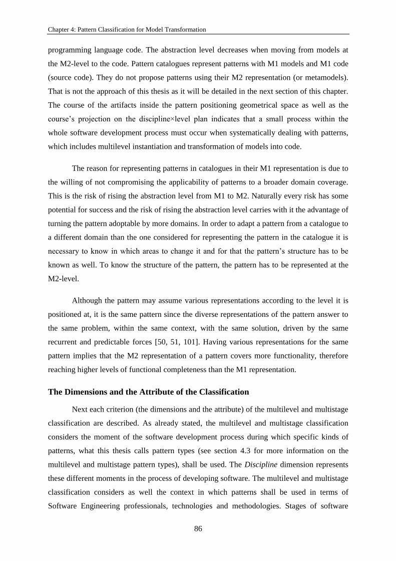
Chapter 4: Pattern Classification for Model Transformation
86
programming language code. The abstraction level decreases when moving from models at
the M2-level to the code. Pattern catalogues represent patterns with M1 models and M1 code
(source code). They do not propose patterns using their M2 representation (or metamodels).
That is not the approach of this thesis as it will be detailed in the next section of this chapter.
The course of the artifacts inside the pattern positioning geometrical space as well as the
course’s projection on the discipline×level plan indicates that a small process within the
whole software development process must occur when systematically dealing with patterns,
which includes multilevel instantiation and transformation of models into code.
The reason for representing patterns in catalogues in their M1 representation is due to
the willing of not compromising the applicability of patterns to a broader domain coverage.
This is the risk of rising the abstraction level from M1 to M2. Naturally every risk has some
potential for success and the risk of rising the abstraction level carries with it the advantage of
turning the pattern adoptable by more domains. In order to adapt a pattern from a catalogue to
a different domain than the one considered for representing the pattern in the catalogue it is
necessary to know in which areas to change it and for that the pattern’s structure has to be
known as well. To know the structure of the pattern, the pattern has to be represented at the
M2-level.
Although the pattern may assume various representations according to the level it is
positioned at, it is the same pattern since the diverse representations of the pattern answer to
the same problem, within the same context, with the same solution, driven by the same
recurrent and predictable forces [50, 51, 101]. Having various representations for the same
pattern implies that the M2 representation of a pattern covers more functionality, therefore
reaching higher levels of functional completeness than the M1 representation.
The Dimensions and the Attribute of the Classification
Next each criterion (the dimensions and the attribute) of the multilevel and multistage
classification are described. As already stated, the multilevel and multistage classification
considers the moment of the software development process during which specific kinds of
patterns, what this thesis calls pattern types (see section 4.3 for more information on the
multilevel and multistage pattern types), shall be used. The Discipline dimension represents
these different moments in the process of developing software. The multilevel and multistage
classification considers as well the context in which patterns shall be used in terms of
Software Engineering professionals, technologies and methodologies. Stages of software

4.2. Multilevel and Multistage Classification
87
development are defined by different profiles of Software Engineering professionals who
work with different kinds of technologies and methodologies tailored to their profiles. The
Stage dimension represents these different stage-related professionals, technologies and
methodologies in the process of developing software. The classification in this thesis also
considers a modeling infrastructure that was adopted to avoid subjective decisions on the
application of patterns, and situations of misinterpretation and corruption of patterns from
catalogues while interpreting and adapting them respectively. The modeling infrastructure
considered is the OMG modeling infrastructure. The Level dimension represents the different
levels of the OMG modeling infrastructure. Finally the multilevel and multistage
classification takes into account that domain-specific artifacts for the development of families
of software products are common these days, which means that the applicability of patterns to
particular domain natures allows to choose between the patterns that are most adequate to a
domain of a software product or family of products. The Domain Nature attribute represents
the different (both) domain natures to which patterns are most applicable (or the applicability
of patterns to both domain natures).
As the subtitles indicate, the Discipline dimension can take the values {business
modeling, requirements, analysis & design, implementation} and the Stage dimension can
take the values {inception, elaboration, construction}. The Level dimension corresponds to
the levels of the OMG modeling infrastructure {M1, M2}. For now M3 is not being
considered. M3 is not being represented in the figures because M3 can be represented with
(UML) models and the classification in this chapter was not yet worked at that level. Despite
that, M0 is represented in the figures to remember that after M1 code (compile-time code)
there is M0 code (runtime code) but runtime code is not relevant to the classification in this
chapter. The Domain Nature attribute which was already explained earlier in this section of
the chapter can take the values {vertical, horizontal, agnostic}.
In order to use this classification do the following: (1) analyze the pattern you want to
classify according to the dimensions Discipline and Stage, and give a value to each of those
dimensions for that pattern you are classifying; (2) conclude on the pattern type (see section
4.3 for more information on the multilevel and multistage pattern types and how the
dimensions Discipline and Stage determine the pattern type); (3) determine the pattern’s level,
which corresponds to giving a value to the Level dimension; (4) if the pattern is not
represented in its M2 representation, draw an M2 model of the pattern; (5) by looking at the
M2 representation of the pattern describe its semantics in textual form; and finally (6) by

Chapter 4: Pattern Classification for Model Transformation
88
looking at the pattern’s M2-level textual description and at the pattern’s description in the
catalogue classify the pattern in what its domain nature is concerned, which is equivalent to
tagging the pattern with one of the three possible values for the Domain Nature attribute.
The assignment of patterns to particular chunks of the classification is dependent on
the pattern type, therefore on the RUP’s textual descriptions of its disciplines and phases (to
conduct step 1). In order to determine the pattern’s level the classifier (the subject who
classifies) must be familiarized with the Four-Layer Architecture since he has to understand
if the concepts the pattern presents are situated at the M2 or at the M1 levels. The classifier
has to know the notion of multilevel instantiation. The classification process is dependent on
the subject who conducts the process. Determining the pattern type is subjective as it implies
looking at the textual descriptions of the RUP’s disciplines and phases. Analyzing textual
descriptions is subjective (at least in this approach). Determining the pattern’s level is also
subjective (at least in this approach) because it depends on the classifier’s knowledge.
The Discipline Dimension
The RUP’s Business Modeling Software Engineering Discipline
The RUP’s Business Modeling discipline shall comprise activities of derivation of the
software requirements the system to be developed must support in order to be adequate to the
target organization and of analyzing how that system fits into the organization. The goal of
the Business Modeling discipline is to model an organizational context for the system.
The RUP’s Requirements Software Engineering Discipline
The RUP’s Requirements discipline shall comprise activities of stakeholder request
elicitation and of transformation of those requests into requirements on the system to be
developed. Those requirements shall span the complete scope of the system. The
requirements on what the system shall do have to be agreed with the stakeholders (customer
and others). The goal of the Requirements discipline is to provide developers with a better
understanding of the requirements the system must fulfill based on the customer’s (or other
stakeholder’s) requests. It is also the goal of this discipline to delimit the boundaries of the
system to be developed.
The RUP’s Analysis & Design Software Engineering Discipline
The RUP’s Analysis & Design discipline shall comprise activities of transformation of
the requirements elicited with the stakeholders into a design of the system to be deployed.

4.2. Multilevel and Multistage Classification
89
The design of the system shall contemplate an architecture for the system. The goal of this
discipline is to specify the design of the system to be developed.
The RUP’s Implementation Software Engineering Discipline
The RUP’s Implementation discipline shall comprise activities of development, unit
testing of the developed components and integration of the software components that will
allow the system requested by the stakeholders to be deployed based on the design
specifications elaborated in the context of the Analysis & Design discipline. When
developing the system, the organization of the code shall be defined according to the layers of
the subsystems to implement. Developing the system through components implies that all the
components produced by different teams are integrated into an executable system. The goal
of this discipline is to translate the design elements that came up in the context of the
Analysis & Design discipline into implementation elements (source files, binaries, executable
programs and others).
The Stage Dimension
The RUP’s Inception Software Development Stage
The RUP’s Inception stage shall comprise activities of discrimination of the critical
use cases of the system and the primary operation scenarios vital to the design tradeoffs that
will have to be made later on during the process. At least one candidate architecture shall be
exhibited (and maybe demonstrated) and shall support the primary scenarios (or at least some
of them) in order for the stakeholders to agree upon the fulfillment of the requests they
exposed to the Software Engineers responsible for the requirements elicitation. The goal of
this stage is to ensure that the software development project is both worth doing and possible
to execute.
The RUP’s Elaboration Software Development Stage
The RUP’s Elaboration stage shall comprise activities of architecture handling like
ellaborating a baseline architecture of the system, thus providing a stable basis for further
design and implementation work which will take place during the Construction stage. This
architecture shall contemplate and reflect the most significant requirements for the
architecture of the system. Architectural prototypes shall be used to evaluate the stability of
the architecture. The goal of this stage is to elaborate an architectural foundation for the
upcoming detailed design and implementation efforts.

Chapter 4: Pattern Classification for Model Transformation
90
The RUP’s Construction Software Development Stage
The RUP’s Construction stage shall comprise activities of development of deployable
software products from the baseline architecture of the system elaborated during the prior
stage. The design, development and testing of all the requested functionality for the system
shall be completed during this stage. The construction of the software system shall be
conducted in an iterative and incremental way. It is during the construction of that software
system that remaining use cases and other requirements are described, others are further
detailed, the design built during the previous stage is enlivened and the implemented software
is tested. The goal of this stage is to develop a complete software product ready to transition
to the users.
The Level Dimension
The Level dimension of the classification corresponds to the abstraction levels of the
Four-Layer Architecture. Each model in the Four-Layer Architecture except for the one at the
highest level is an instance of the one at the higher level. The M0-level refers to the data
manipulated by software. The M1-level refers to models of user concepts. The M2-level
refers to UML concepts models. These are models of models and so are called metamodels.
A metamodel is a model whose elements are types in another model (an example of a
metamodel is the UML metamodel). It describes the structure of the models, the elements that
are part of those models and their properties. The meta-metamodels are at the highest level of
the modeling infrastructure, the MOF (Meta-Object Facility) [102] or M3-level.
The Domain Nature Attribute
The Domain Nature attribute indicates whether the pattern is more adequate to
vertical domains (industry, commerce, services and others) or to horizontal domains
(accounting, stock, project management and others). Some patterns as it will be evidenced
later in this chapter are domain nature agnostic, which means that they are applicable both to
vertical and to horizontal domains.
4.3. Pattern Classification Types
Following are the pattern types from the multilevel and multistage classification. A
pattern type represents a kind of pattern that is classified with the same Discipline
dimension’s value and the same Stage dimension’s value. A description is provided for each
of the pattern types as well as the classification according to the Discipline and Stage
dimensions. The classification of pattern types according to the Level dimension does not

4.3. Pattern Classification Types
91
make sense as it depends on the representation of the pattern and has no influence on the
definition of the pattern types themselves. The pattern types are: business patterns, analysis
patterns, enterprise patterns, architectural patterns, design patterns and implementation
patterns. These names were chosen because they are the most common pattern names in the
literature and make the most sense in this thesis’ definitions of the pattern types.
This section will expose some examples of patterns that were classified with different
pattern types. The patterns in this section suit the purpose of demonstrating how this thesis
has applied the multilevel and multistage classification of patterns. This thesis provides for a
representation of the patterns as M2-level (meta)models and as M1-level models (when
applicable).
Be aware that some of the patterns that are going to be analyzed in this section were
not classified with the same pattern type name they were classified with using the
classification in this chapter. For instance the Posting pattern was classified as a business
pattern by Pavel Hruby in [103] but this thesis classifies it as an analysis pattern.
Business Patterns
The term business pattern is inspired on IBM’s definition of business pattern [92].
Business patterns are more pertinent in the context of vertical domains. They make
the most sense to be handled during the Inception stage by professionals, technologies and
methodologies from the Business Modeling and Requirements disciplines.
Business patterns are used to describe a solution to accomplishing a business
objective. They shall address the users of the solution, the organization’s software systems
the users interact with (or the organization itself) and the organization’s information
(available through those systems or the organization itself). Business patterns may refer to e-
business solutions that convey an organizational framing, validity and conformance of the
solution to the business problem the solution is trying to solve. Software solutions shall be
sustained by the business and this is achieved with the adoption of business patterns.
Examples of business patterns can be seen in [92] and also in [52].
Figure 38 (on the left) illustrates the positioning of business patterns according to the
Stage and the Discipline dimensions.

Chapter 4: Pattern Classification for Model Transformation
92
Figure 38 – The business patterns’ positioning according to the Stage and the Discipline dimensions
(on the left). The Domain Model pattern modeled at both the M2 and the M1 levels of the OMG
modeling infrastructure (on the right).
The Domain Model Pattern
The Domain Model pattern’s goal is to produce an object model of the domain or
business area. A domain model must distinguish between the data the business involves and
the business rules (or the rules used by the business). The behavior expressed by these
business rules shall be placed in the business object that really needs it. Figure 38 (on the
right) shows a model with an example of the Domain Model pattern in the M1 representation
as well as the M2 representation of the pattern. The Domain Model pattern is composed of
two types of concepts: business objects (or domain objects) and business rules. This is
evidenced by the Domain Model M2 model in Figure 38 (on the right).
The Domain Model pattern suits the modeling of every business domain possible as
every business domain has business objects and business rules on those objects. Even though
the pattern is applicable to all business domains it is not appropriate to the modeling of a
horizontal domain or to the modeling of structural business domain commonalities, which
makes of it applicable to domains of vertical nature.
The Domain Model pattern does not show how to model objects or rules for a specific
business domain but the types of concepts the pattern handles are business-related and shall
be instantiated in order to model business domains. Besides and more important than that, the
Domain Model pattern allows to model objects and rules that shall be handled by the solution
to the business problem the solution is trying to solve. The Domain Model pattern is a very
atomic pattern as it does not address the users of the solution or the organization’s software

4.3. Pattern Classification Types
93
systems the users interact with (or the organization itself); nonetheless it is adequate to reach
the business domain model from the candidate architecture that shall be exhibited to the
stakeholders. For all of these reasons this thesis considers that the Domain Model pattern
shall be classified as a business pattern.
By looking at the RUP’s textual descriptions of its disciplines and phases, this thesis
concluded that the Domain Model pattern shall be used during the Inception software
development stage and in the context of the Business Modeling and Requirements Software
Engineering disciplines as seen in the previous section of this chapter. During the Inception
stage a domain model must be built from a candidate architecture that translates the critical
use cases and the primary operation scenarios. That domain model may be achieved with the
application of the Domain Model pattern. The pattern shall help translating the requirements
elicited with the stakeholders. Those requirements have to be adequate to the target
organization, which is a concern of the Requirements discipline.
Analysis Patterns
The term analysis pattern is inspired on Fowler’s definition of analysis pattern [94].
Analysis patterns are more applicable to horizontal domains. They shall be used
during the Inception stage by professionals, technologies and methodologies from the
Business Modeling and Requirements disciplines. In spite of being called analysis patterns it
does not make sense to use them in the context of the Analysis & Design discipline. They
were called so because analysis pattern is a terminology spread out the literature and also
because Fowler’s definition of analysis pattern inspired the definition of analysis pattern in
this thesis. In an older informal terminology, the development of software is composed of
three phases: analysis, design and implementation. With RUP formalizing the dimension of
business modeling in the process of software development, analysis was divided into business
modeling and requirements. The former design discipline corresponds to RUP’s Analysis &
Design.
Analysis patterns are solutions to recurrent problems in many (business) domains.
They are composed of concepts that represent structural commonalities when modeling many
different business domains.
Examples of analysis patterns can be seen in [94].
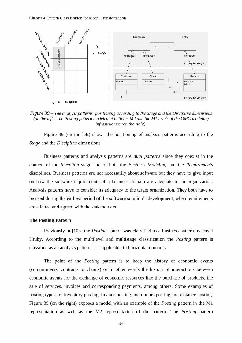
Chapter 4: Pattern Classification for Model Transformation
94
Figure 39 – The analysis patterns’ positioning according to the Stage and the Discipline dimensions
(on the left). The Posting pattern modeled at both the M2 and the M1 levels of the OMG modeling
infrastructure (on the right).
Figure 39 (on the left) shows the positioning of analysis patterns according to the
Stage and the Discipline dimensions.
Business patterns and analysis patterns are dual patterns since they coexist in the
context of the Inception stage and of both the Business Modeling and the Requirements
disciplines. Business patterns are not necessarily about software but they have to give input
on how the software requirements of a business domain are adequate to an organization.
Analysis patterns have to consider its adequacy to the target organization. They both have to
be used during the earliest period of the software solution’s development, when requirements
are elicited and agreed with the stakeholders.
The Posting Pattern
Previously in [103] the Posting pattern was classified as a business pattern by Pavel
Hruby. According to the multilevel and multistage classification the Posting pattern is
classified as an analysis pattern. It is applicable to horizontal domains.
The point of the Posting pattern is to keep the history of economic events
(commitments, contracts or claims) or in other words the history of interactions between
economic agents for the exchange of economic resources like the purchase of products, the
sale of services, invoices and corresponding payments, among others. Some examples of
posting types are inventory posting, finance posting, man-hours posting and distance posting.
Figure 39 (on the right) exposes a model with an example of the Posting pattern in the M1
representation as well as the M2 representation of the pattern. The Posting pattern

4.3. Pattern Classification Types
95
contemplates two types of concepts: dimensions and entries. A posting dimension is either an
economic agent or an economic resource. The purpose of the dimension is to provide
additional information about the economic event or in other words provide descriptive
information about the posting entries. A posting entry is an entry of a commitment, a contract
or a claim. The purpose of the entry is to keep track of the history of economic events. In
Figure 39 (on the right) it can be seen that Customer and Check are two posting
dimensions of the posting entry Receipt. Most probably the Customer class represents
the economic agent involved in the economic event represented by the entry class Receipt
whereas the Check class represents the economic resource.
The Posting pattern is constituted by concepts belonging to a horizontal domain (the
accounting domain). Nevertheless the Posting pattern has only the concept of posting entry in
common with the Accounting pattern (in the Accounting pattern the concept of posting entry
corresponds to the concept of agreement).
The arguments for classifying the Posting pattern as an analysis pattern as well as for
its adequacy to the Inception software development stage, and the Business Modeling and
Requirements Software Engineering disciplines are the same described beforehand for the
Accounting pattern.
Enterprise Patterns
The term enterprise pattern is inspired on Fowler’s considerations about enterprise
patterns and enterprise software in [104].
Enterprise patterns are most adequate to vertical domains. They are more relevant in
the context of the Elaboration stage by professionals, technologies and methodologies from
the Analysis & Design discipline.
Enterprise patterns are used in the development of software systems on which various
businesses rely on and run (the so called enterprise software systems). Normally the
architecture of such systems is a layered architecture. Ellaboration decisions on layered
architectures are design decisions that have to be taken inside a logical layer or between
different logical layers. Often single enterprise applications need to interact so enterprise
patterns have also to propose solutions to the integration of enterprise applications problem.
Validations, calculations and business rules on the data an information system manipulates

Chapter 4: Pattern Classification for Model Transformation
96
vary according to the domain and change as the business conditions change. Enterprise
applications must respond to ever changing business requirements.
Enterprise patterns address architectural concerns as well as the architecture patterns
this thesis will be talking next but whereas enterprise patterns are mainly concerned with
topological architecture, architectural patterns are mainly concerned with logical architecture.
This chapter does not consider the notion of enterprise as the RUP does not consider
it. The RUP is a Software Engineering process framework. IBM has delivered a RUP plug-in
called RUP SE (RUP for Systems Engineering) [105]. The RUP SE has enlarged the RUP
with the consideration that the development of large-scale systems must be concerned with
software, hardware, workers and information. The RUP SE considers different perspectives
on the system (logical, physical, informational, and others). The RUP SE is shortly a
framework for addressing the overall system’s issues. The RUP SE addresses behavioral
requirements (the way the system shall behave in order to fulfill its role in the enterprise).
The RUP does not express such concern with the enterprise in which the system will play its
role. In fact this kind of concern is more from the field of Systems Engineering than from the
field of Software Engineering. System requirements in the context of Software Engineering
are specifically software system requirements. The system requirements are derived from an
understanding of the enterprise, its services and the role that the system (software-based or
not) plays in the enterprise. For instance the RUP SE suggests that the enterprise shall be
partitioned into the system and its actors in order to derive the system requirements. In the
RUP SE an enterprise is faced as a set of collaborating systems that collaborate to realize
enterprise services, mission and others. The system attributes are obtained from an analysis of
the enterprise needs. As this chapter talks about software system development patterns in the
context of RUP (not RUP SE), this chapter is related to Software Engineering, not to Systems
Engineering, which means that this chapter’s enterprise patterns have nothing to do with the
concept of enterprise from the Systems Engineering field. The term enterprise pattern comes
from the term enterprise application architectural pattern from Folwer’s book “Patterns of
Enterprise Application Architecture” [91].
Examples of enterprise patterns can be seen in [91].
Figure 40 (on the left) depicts the positioning of enterprise patterns according to the
Stage and the Discipline dimensions.

4.3. Pattern Classification Types
97
Figure 40 – The enterprise patterns’ positioning according to the Stage and the Discipline
dimensions (on the left). The Service Layer pattern modeled at both the M2 and the M1 levels of the
OMG modeling infrastructure (on the right).
The Service Layer Pattern
In [91] Fowler classified the Service Layer pattern as an enterprise application
architectural pattern. According to the multilevel and multistage classification the Service
Layer pattern is classified as an enterprise pattern.
The purpose of the Service Layer pattern is to provide for operations to access the
enterprise application’s stored data and business logic. The Service Layer pattern can be
implemented with a set of facades over a domain model. The classes implementing the
facades do not implement any business logic, which is implemented by the business object’s
rules from the domain model. The facades gather the operations the application has available
for interaction with client layers. The Service Layer can also be implemented with classes
directly implementing the application logic and delegating on business object classes for
domain logic processing. Application logic is grouped into classes of related application
logic. These classes are application service classes. Figure 40 (on the right) depicts an
example of this second strategy for implementing the Service Layer pattern at the modeling
level. The figure shows a model with an example of the Service Layer pattern in the M1
representation as well as the M2 representation of the pattern. As it may be concluded from

Chapter 4: Pattern Classification for Model Transformation
98
the figure, the Service Layer pattern is composed of two types of concepts: application
services and domain services. Business objects are also represented in the models as the
domain services rely on them for business logic. The domain services act as intermediates
between the application services and the business objects since they provide for calls to
application logic in application services and for calls to business logic residing on business
objects. These last calls are made inside the service operations the domain services provide
for, which correspond to the use cases the actors want to perform with the application.
As the main focus of the Service Layer is the domain service acting as a bridge
between the application logic and the business logic, and not implementing any business
domain logic (just accessing it) this thesis has tagged this particular enterprise pattern as
domain nature agnostic.
The Service Layer pattern is classified in this chapter as an enterprise pattern because
it is used to develop enterprise software systems for specific business domains. When
developing enterprise applications, logical layers are essential and the concern of the Service
Layer pattern (to separate application logic from business logic) proves that it is an enterprise
pattern.
By looking at the RUP’s textual descriptions of its disciplines and phases this thesis
concluded that the Service Layer pattern shall be used during the Elaboration software
development stage and in the context of the Analysis & Design Software Engineering
discipline. Since splitting application logic from business logic is an architectural decision
with impacts at the level of the baseline software system architecture it makes sense to adopt
the Service Layer pattern during the Elaboration stage and by the professionals, technologies
and methodologies responsible for the software design.
Architectural Patterns
The term architectural pattern is inspired on Buschmann, et al. and Zdun [8, 106].
Architectural patterns are more appropriate to horizontal domains. They shall be
picked up from catalogues for usage during the Elaboration stage by professionals,
technologies and methodologies from the Analysis & Design discipline.
Architectural patterns are used in the definition of the structure of software solutions.
The architecture of a system is the design artifact that represents the functionality-based

4.3. Pattern Classification Types
99
Figure 41 – The architectural patterns’ positioning according to the Stage and the Discipline
dimensions (on the left). The MVC pattern modeled at both the M2 and the M1 levels of the OMG
modeling infrastructure (on the right).
structure of that system and shall address quality or non-functional attributes wished-for the
system. Architectural patterns shall help improving both the functional and the quality
attributes of software systems.
Examples of architectural patterns can be seen in [8].
Figure 41 (on the left) shows the positioning of architectural patterns according to the
Stage and the Discipline dimensions.
Enterprise patterns and architectural patterns are dual patterns since they coexist in
the context of the Elaboration stage and of the Analysis & Design discipline.
The Model-View-Controller Pattern
Originally in [8] the MVC pattern was classified by Buschmann, et al. as an
architectural pattern. According to the multilevel and multistage classification the MVC
pattern is classified as an architectural pattern. It is adequate to both horizontal and vertical
domains, so it is agnostic relatively to the domain nature.
The purpose of the MVC pattern is to ensure the consistency between the user
interface and the business information of a software system. The separation of the user
interface from the business information of a software system provides for user interface
flexibility. Figure 41 (on the right) depicts an example of a model of the MVC pattern in the
M1-level and also the MVC pattern represented in the M2-level. The MVC pattern is

Chapter 4: Pattern Classification for Model Transformation
100
composed of three types of classes: a model, a view and a controller. The model contains the
business information that is to be presented to the user. The view obtains the information
from the model and displays it to the user. The controller is responsible for requesting the
business information updating on the model upon user action (event) on the graphical
interface (view). It takes the business information from the view and requests for the model’s
updating with that information.
Although the model component contains business information the MVC pattern is
adequate to both horizontal and vertical domains, which makes of it agnostic in what its
domain nature is concerned. The pattern can either be adopted if the business information is
relative to horizontal business objects or to vertical business objects.
The MVC pattern is classified as an architectural pattern according to the multilevel
and multistage classification since it is used to define the structure of the software system,
namely the structure of the client-side of the system. The pattern allows for the software
system to be flexible concerning its user interface, which is a quality attribute wished-for that
system. Mainly the MVC pattern is responsible for the structure of the client-side of the
software system in order for it to be able to update business information upon events
triggered by the user on the user interface (which allows the system to provide for the update
functionality to the user).
By looking at the RUP’s textual descriptions of its disciplines and phases this thesis
concluded that the MVC pattern shall be used during the Elaboration software development
stage and in the context of the Analysis & Design Software Engineering discipline. As the
MVC pattern is used to define the structure of the client-side of the system, addressing both
the update functionality and the user interface flexibility (non-functional requirement), it shall
be part of the system’s architecture, which shall be part of the system’s design specification.
The system’s baseline architecture shall contemplate the most significant architectural
requirements, and the MVC pattern addresses the consistency between the user interface and
the business information of the software system (which is a requirement vital to interactive
software systems).
Design Patterns
The term design pattern is inspired on the GoF’s patterns.

4.3. Pattern Classification Types
101
Design patterns are domain nature agnostic, which means that they are both
applicable to vertical and to horizontal domains. They shall be manipulated during the
Construction stage by professionals, technologies and methodologies from the Analysis &
Design discipline.
Although the GoF described design patterns as OO software patterns, this thesis
considers design patterns as those that are applicable to the refinement or detailing of the
software system architecture. For instance Larman’s GRAS (General Responsibility
Assignment Software) [93] patterns are design patterns since they have to do with behavioral
aspects that only come up during a mechanistic design of the software solution’s
development (by mechanistic it is meant structural or behavioral mechanisms more refined
than components from logical architectures) [93].
The presence of code in design patterns is only to give examples. Design patterns are
independent of the language, as can be seen from the GoF catalogue (they only talk about OO
concepts, not language features). The sample code section provides for code to illustrate the
example given in the motivation section, where the reader is given a scenario to illustrate a
design problem in order for him to better understand the more abstract description of the
pattern that follows the motivation section. Again the code is an illustration of the pattern’s
applicability.
Figure 42 (on the top left) depicts the positioning of design patterns according to the
Stage and the Discipline dimensions.
Figure 42 (on the bottom left) illustrates the difference between the definition of
design pattern in this thesis and GoF’s. The lighter grey area corresponds to the pattern
positioning space of the GoF catalogue. The darker grey area corresponds to the pattern
categorization area of the classification in this chapter where the design patterns of this
classification are positioned. These areas were drawn taking only the Discipline and the Stage
dimensions into consideration as the Level dimension does not allow demonstrating the
difference between both definitions. This thesis considers that design patterns shall only be
used during the Construction stage of the software development process as the Software
Engineering professionals, technologies and methodologies of the Analysis & Design are the
most adequate to handle these patterns due to their professional profile and adequacy to the
Construction stage’s activities and goals. It also considers that if design patterns are handled
throughout the whole software development stages and by the people and tools (technologies

Chapter 4: Pattern Classification for Model Transformation
102
Figure 42 – The positioning of design patterns according to the Stage and the Discipline dimensions
(on the top left). The difference between the design patterns of the classification this thesis presents
and the GoF’s according to the Stage and the Discipline dimensions (on the bottom left). The Adapter
pattern modeled at both the M2 and the M1 levels of the OMG modeling infrastructure (on the right).
and methodologies) of every Software Engineering discipline, the advantages predicted in
pattern catalogues of the adopted design patterns are not going to be preserved and that the
design patterns in the catalogues are not going to be used in their full potential by the people
most skilled to handle them.
The Adapter Pattern
In the past in [50] the Adapter pattern was classified as a design pattern by the GoF
but in the sense of OO software pattern. According to the multilevel and multistage
classification the Adapter pattern is classified as a design pattern. It is applicable to both
horizontal and vertical domains, which makes of it a domain nature agnostic pattern.
The Adapter pattern (also known as Wrapper) has to do with a class converting the
interface of one class to be what another class expects. Figure 42 (on the right) shows a
model exemplifying the Adapter pattern in its M1 representation as well as the M2
representation of the pattern. This is what the Adapter’s implementation described at the M2-
level should look like: “The Adapter must have an input parameter of the Adapted’s type
in its constructor and extend the Required and call the Adapted’s appropriate operation

4.3. Pattern Classification Types
103
inside the operation required by the Receptacle”. The Adapter’s description at the M2-
level in terms of semantics is the following: “The Receptacle requires the Adapted to
be adapted to the Required through the Adapter (the process is called adaptation). The
goal is for the Receptacle to be able to call the Required’s operation from an instance
of the Adapted”.
The Adapter pattern is independent from any domain (or domain nature agnostic)
because the adapter, the adapted, the required and the receptacle objects can belong to every
domain possible. As long as the semantics or business logic (at the M1-level) specific of a
certain domain complies to the M2 semantics described in the previous paragraph, the
Adapter pattern is applicable to that domain no matter what the business is.
The Adapter pattern deals with classes and their operations that implement the
interface operations those classes are expected to implement. Essentially the contents of those
operations that are of relevance to the Adapter pattern are calls to other operations. As can be
seen, this thesis is not arguing about business logic implemented by the class’ operations,
rather about the structure of the classes targeted by the adaptation, which means this thesis is
discussing structural aspects rather than behavioral. Nevertheless and once again, the Adapter
pattern shall be applied during the mechanistic design of the system’s development when
classes shall be derived from architectural components. The Adapter pattern in its semantics
shall be used to detail the baseline software system architecture and be part of a design
specification containing the interface design of the classes involved in the adaptation process.
For all these reasons this thesis classified the Adapter pattern as a design pattern.
By looking at the RUP’s textual descriptions of its disciplines and phases this thesis
concluded that the Adapter pattern shall be used during the Construction software
development stage and in the context of the Analysis & Design Software Engineering
discipline as already argued in this chapter. The adequacy of such stage and discipline to the
Adapter pattern is intimately related to the reasons that were just exposed for classifying the
Adapter pattern as a design pattern.
Implementation Patterns
The term implementation pattern is inspired on Beck’s definition of implementation
pattern [51].
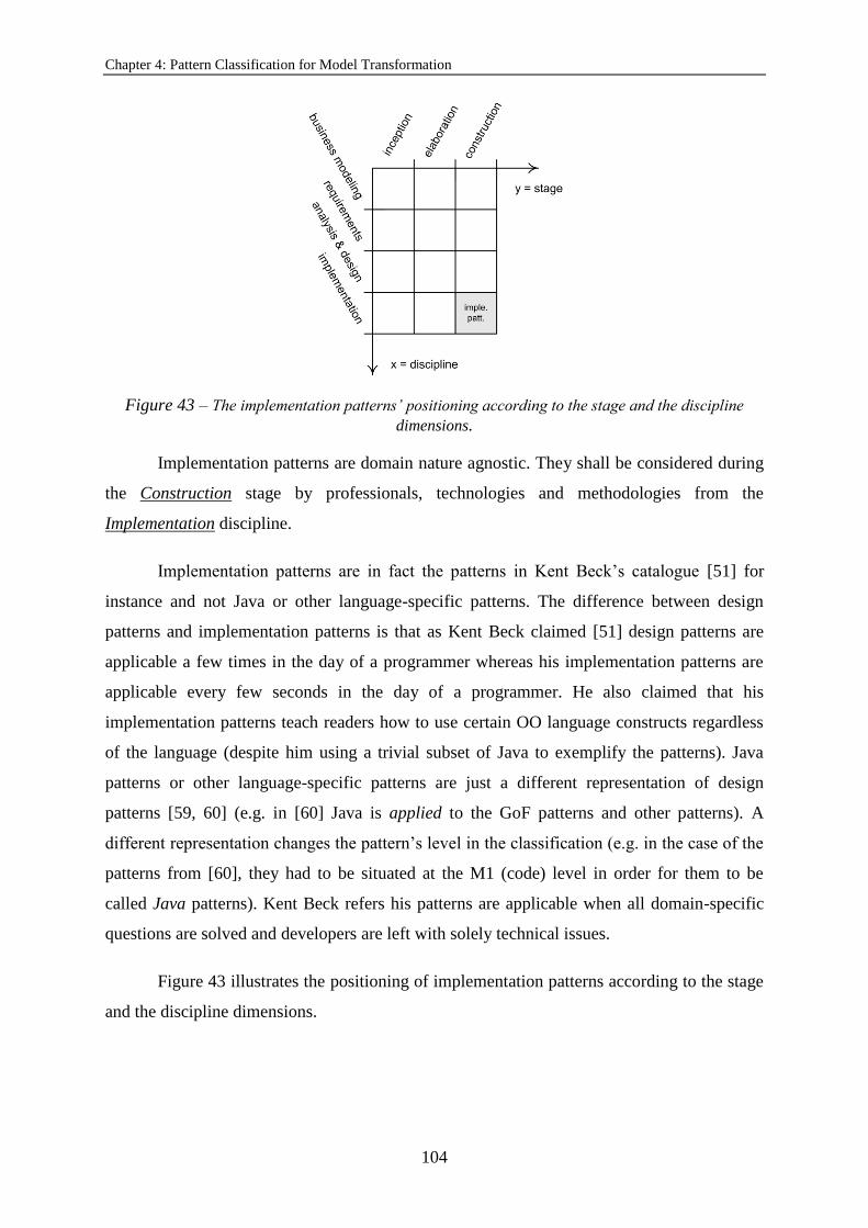
Chapter 4: Pattern Classification for Model Transformation
104
Figure 43 – The implementation patterns’ positioning according to the stage and the discipline
dimensions.
Implementation patterns are domain nature agnostic. They shall be considered during
the Construction stage by professionals, technologies and methodologies from the
Implementation discipline.
Implementation patterns are in fact the patterns in Kent Beck’s catalogue [51] for
instance and not Java or other language-specific patterns. The difference between design
patterns and implementation patterns is that as Kent Beck claimed [51] design patterns are
applicable a few times in the day of a programmer whereas his implementation patterns are
applicable every few seconds in the day of a programmer. He also claimed that his
implementation patterns teach readers how to use certain OO language constructs regardless
of the language (despite him using a trivial subset of Java to exemplify the patterns). Java
patterns or other language-specific patterns are just a different representation of design
patterns [59, 60] (e.g. in [60] Java is applied to the GoF patterns and other patterns). A
different representation changes the pattern’s level in the classification (e.g. in the case of the
patterns from [60], they had to be situated at the M1 (code) level in order for them to be
called Java patterns). Kent Beck refers his patterns are applicable when all domain-specific
questions are solved and developers are left with solely technical issues.
Figure 43 illustrates the positioning of implementation patterns according to the stage
and the discipline dimensions.
4.4. Conclusions
105
The Value Object Pattern
In [51] the Value Object pattern was classified as a class pattern. In the context of the
multilevel and multistage classification the Value Object pattern is classified as an
implementation pattern. It is adequate to both horizontal and vertical domains, which means
that it is domain nature agnostic.
The purpose of the Value Object pattern is to create objects that once created cannot
have the values of the variables they handle changed. The solution is to set the value of those
variables when the object is created through its constructor. No other assignments shall be
made to those variables elsewhere in the object’s class. Operations on the object shall always
return new objects that shall be stored by the requester of the operation. Shortly value objects
are objects representing mathematical values, which are values that do not change over time
(have no state). For instance a transaction (value object) shall not change over time, rather an
account changes over time (a transaction implies a change of state in the account). It does not
make sense to model implementation patterns as they are only to exist in code, not in models,
which implies that they are always represented at the M1-level (compile-time code).
The Value Object pattern shall be involved in the coding of both horizontal and
vertical domain software systems since it is about the construction of objects that shall not
change over time, the assignment of values to those objects’ variables and the operations on
those (value) objects.
The Value Object pattern is classified as an implementation pattern because it is about
the technical details of using classes (an OO language construct), to create objects that shall
have no state (whose variables’ values shall not change over time), in this case.
By looking at the RUP’s textual descriptions of its disciplines and phases this thesis
concluded that the Value Object pattern shall be used during the Implementation software
development stage and in the context of the Construction Software Engineering discipline as
previously mentioned in this chapter. The Value Object is related to the development of
software systems, particularly to the development of implementation elements (source code).
4.4. Conclusions
Some lessons were learned on the application of the multilevel and multistage pattern
classification to some patterns from the literature. After looking at the RUP’s textual
descriptions of its disciplines and phases, some patterns were not classified with the expected

Chapter 4: Pattern Classification for Model Transformation
106
pattern type. This means that a procedural referential such as the RUP is important to classify
patterns, mainly because it gives the classification a notion of software development process.
It also means that the awareness of the adequacy of a pattern in a catalogue to a specific
discipline and stage changed after the multilevel and multistage pattern classification was
elaborated. Initially before an in depth analysis of the RUP’s textual descriptions and the
definitions of the various pattern types it was expected that (1) analysis patterns did not make
sense in the context of the RUP’s Business Modeling discipline; (2) design patterns made
sense in the context of both the RUP’s disciplines of Analysis & Design and Implementation,
and of both the RUP’s Elaboration and Construction stages; and (3) patterns that could be
contextualized in the RUP’s Implementation discipline and in the RUP’s Construction phase
were language-specific patterns. After analyzing RUP’s textual descriptions and the pattern
type definitions, this thesis concluded that (1) analysis patterns do make sense in the context of
the RUP’s Business Modeling discipline; (2) design patterns make only sense in the context of
the RUP’s Analysis & Design discipline and the RUP’s Construction stage;
and (3) language-specific patterns are a translation of design patterns into some language, not
implementation patterns.
One of the reasons in the genesis of the multilevel and multistage classification’s
creation was to provide for some guidance on the adoption of software development patterns
in order to avoid loosing the original advantages of the pattern throughout the adoption
process. For this reason this thesis considered the pattern classification had to rely on the
software development process. The benefits of such an approach to pattern classification are:
(1) the knowledge of the moment from the software development process in which to use
specific kinds of patterns; and (2) the knowledge of who the Software Engineering
professionals most skilled to handle those specific kinds of patterns in each stage of the
software development process are, considering their instruments (technologies and
methodologies).
The systematic character of the multilevel and multistage classification is based on the
objectiveness of the decisions on the application of software development patterns, which
may be assured with the adoption of a modeling infrastructure. A systematic use of software
development patterns is likely to also prevent the misinterpretation and corruption of patterns
from catalogues when interpreting and adapting them, respectively.

4.4. Conclusions
107
Besides being concerned with the stages and the Software Engineering professional’s
skills and the instruments they handle to conduct Software Engineering activities, and besides
translating concerns with the systematic use of software development patterns the multilevel
and multistage classification is also concerned with the nature of the domain, which is one of
the criteria that composes the classification. Therefore the multilevel and multistage
classification is focused on domain-based software development. The classification also
focuses on model-driven software development since it incorporates (through its multilevel
character) the OMG modeling infrastructure by considering that patterns can be represented
at different levels of that infrastructure, which influences their interpretation.
The multilevel and multistage pattern classification is innovative in some ways
relatively to the existing literature. Most pattern classifications do not classify patterns based
on the software development process. The only classification that does, disregarded the
analysis phases (business modeling and requirements) of the software development process.
The multilevel and multistage classification, though, addresses business modeling and
requirements.
The architectural patterns (like the MVC pattern the 4SRS uses to transform user
functional requirements dealt with during the analysis of software into systems functional
requirements dealt with in the beginning of software design) were concluded to be adequate
for the Elaboration software development stage and in the context of the Analysis & Design
Software Engineering discipline. The incorporation of the MVC in the structure of the logical
architectures the 4SRS generates is supported by this conclusion. The formulation of the
method to refine logical architectures with variability support yield by chapter 3 is also
supported by the pattern classification presented in this chapter.

Chapter 4: Pattern Classification for Model Transformation
108

109
Section 5.2 shows the extension of the SPEM this thesis proposes for defining a visual language to model
transition (from the analysis to the design of software) methods and formalize small dedicated software
development processes like the 4SRS.
Section 5.3 shows the preparation necessary for the automation of transition methods modeled with the
SPEM, particularly the work undertaken to prepare the automation of the 4SRS.
Section 5.4 provides for an insight over the impact of automating transitions methods (like the 4SRS) in
contexts of variability.
5. Automating Model
Transformations
5.1. Introduction
A method can be defined as a general description of how to develop software and
systems. Method modeling is also essential when it comes to process modeling. The same
method can be used by many different processes and more than once in the same process.
The definition of a software process may be time-consuming and labor-intensive,
which means that defining a new process for each software development project may be
unfeasible. In order to promote software processes and the reuse of methods, various PMLs
(Process Modeling Languages) such as the SPEM have been proposed. PMLs shall be used to
convey better comprehension [76, 77], communication, reuse, evolution and management

Chapter 5: Automating Model Transformations
110
[76] of processes, besides used to define or formalize methods and processes, and reuse those
definitions or formalizations in several and different process enactments.
The SPEM (2.0) is a standard metamodel based on the MOF that reuses some
concepts from the UML (2.x) Infrastructure (e.g. Classifier and Package). The SPEM is a
modeling language that contains the minimal elements to define or formalize software and
systems development processes. The SPEM is not aimed at being a generic process modeling
language, rather a software and systems development process modeling language.
The 4SRS method allows the iterative and incremental model-based transition from
user functional requirements (represented as use case diagrams) to system functional
requirements (or logical architectures represented as component diagrams). In other words
the transformation of use cases (dealt with during the analysis of software) into logical
architectures (dealt with in the beginning of the design of software) is conducted with a
method specifically elaborated for the purpose. The main concerns of the method are:
(1) guaranteeing that no user requirement is lost when moving from analysis to design;
and (2) assuring that no user requirement that was not elicited with the customer is considered.
The 4SRS method was not formalized with process positioning concerns prior to this
thesis. In order to plug the 4SRS method into larger software development processes it had to
be formalized as a small dedicated software development process. In this sense the method
had to be formalized with a PML. The SPEM is a PML that uses the UML (an OMG standard
with worldwide impact, therefore handled by professionals worldwide to design their
applications and communicate their design decisions), however it does not possess concepts
that sharply express the needs of the 4SRS method with regards to process positioning
concerns. The challenge was to maintain the interoperability the SPEM offers for being a
standard that tools support and simultaneously express the 4SRS transition method in order to
automate it.
Consider a methodology as a composition of methods (composed of techniques),
process and notation. Within an effort to turn the 4SRS a methodology, this chapter shows
how this thesis uses a PML (the SPEM) to model a method (the 4SRS) as a process. UML is
the notation used in the 4SRS method to represent the necessary diagrams. The 4SRS is a
transition method that can be defined as a method that generally describes how to transform
analysis artifacts into design artifacts to develop software (in the case of the 4SRS, use cases
into component diagrams). Therefore this chapter shows how to model transition methods (in
5.1. Introduction
111
this case, the 4SRS) as processes with a process modeling language (the SPEM). Some other
transition methods may for instance describe how to transform design artifacts into
implementation artifacts, or how to generate test artifacts, or how to transform business
modeling artifacts. Since the 4SRS is a method, it can be the basis for formalizing a small
dedicated (at transitioning from analysis to design) software development process that can be
plugged into larger software development processes. One of the goals of this chapter is to
show the extensions that had to be performed to the SPEM in order to habilitate it for the
expression of the 4SRS method’s characteristics.
The general description of how to develop software and systems (a method) shall be
the basis for defining or formalizing software and systems development processes. Software
and systems development processes can be described as sequences of phases and milestones.
The sequence of phases and milestones represents the development lifecycle of the product,
so processes may represent product development lifecycles. In this sense, methods are only
contextualized in a development lifecycle when positioned within a process.
The automation of software processes may be facilitated by process modeling. The
problem this chapter addresses is the automation of transition methods, particularly those
modeled with the SPEM. The 4SRS was modeled with the SPEM in order to formalize it as a
software process. It had to be automated so that it could be enlivened by means of a tool. The
SPEM was chosen because it is standard, in order to benefit from the advantages of using a
standard that is available to every professional of process modeling. Assuming that
disciplines are sets of tasks that can be grouped according to their particular relevance in (a)
specific phase(s) from large software development processes into which small dedicated
software development processes can be plugged, transition methods are methods that describe
how to transform artifacts from one discipline of a large software development process into
artifacts from another discipline of such a process. Transition methods have particularities
regarding other methods. They realize a change in the perspective on the system,
consequently in the artifacts that represent the system from different perspectives, as well as
they mark a change in the discipline of the large software development process. In this
chapter, the 4SRS is used as the example of a transition method modeled with the SPEM to
illustrate the automation of transition methods modeled with the SPEM (in this case, a
transition method that transforms analysis artifacts into design artifacts). The goal of the
automation of transition methods modeled with the SPEM (in this case, the 4SRS) is the
automatic execution of those methods as small dedicated software development processes.

Chapter 5: Automating Model Transformations
112
The intent is to decrease the cost of introducing the method into large software development
processes, facilitating its use. The (semi)automatic execution of the 4SRS transition method
is based on the Moderne. The Moderne is a model-driven tool for process modeling and
execution. The Moderne tool allows the execution of the 4SRS in a model-driven approach,
which implies generating logical architectures through model transformations using a model-
to-model transformation language [65, 98].
Previously this thesis addressed contribution on the representation of variability in use
case diagrams. That contribution is relevant for providing variability support to the 4SRS
transition method. This thesis also addressed contribution on the formalization of the use case
modeling activity with support for variability since it proposed an extension to the UML
metamodel in order to formally provide for both the concrete and abstract syntaxes to
represent the three different types of variability in use case diagrams it has synthesized.
Transformation rules shall be considered as part of process automation tools that
involve model transformations. This chapter presents transformation rules specified with the
ATL model-to-model transformation language [98]. These transformation rules are part of a
process automation tool adapted to perform the model transformations of the 4SRS transition
method: the Moderne [14].
5.2. Extending the SPEM Metamodel
Synopsis of the SPEM
The explicit purpose of the SPEM is to be as simple as to contain the minimal
elements to define or formalize software and systems development processes. Thus it shall
not be considered a generic process modeling language. The SPEM focuses on the structure
of development processes for software and systems. The behavior of those processes is
modeled with UML 2.0 activity diagrams, so the SPEM does not provide elements for
behavior modeling.
The SPEM distinguishes between the concept of process and the concept of method
content. It considers that the concept of process can be divided into process structure and
process behavior. A process structure is a composition of activities. An activity is a (kind of)
work breakdown element. It represents a list of tasks and/or roles and/or work products in use
by a process, and/or even other activities. The breakdown elements that activities may
contain (tasks and/or roles and/or work products in use by the process) can be nested and

5.2. Extending the SPEM Metamodel
113
logically grouped. Activities represent work that can be assigned to roles that intervene on the
process, and require inputs and/or outputs (work products) to be performed. The process
structure is the representation of the process as a static composition of activities that have
temporal dependencies between them. Although temporal dependency is a behavioral
concept, structural diagrams drawn with the icons or stereotypes of the SPEM UML profile
[12] can have tagged values indicating temporal dependency of activities on each other.
Activities are relevant for modeling phases of a development lifecycle (waterfall, iterative
and incremental are three types of development lifecycles). The same role can be used in an
early phase of a development lifecycle and in a later phase of the same development lifecycle,
which may mean that e.g. that role handles different work products in those two different
phases. The process behavior is not the focus of the SPEM, rather of the UML for instance.
A method content can be considered as the set of concepts (tasks, roles and work
products) that allows representing software and systems development methods and
techniques independently of their positioning within a specific software and systems
development lifecycle (consider that a method is composed of many techniques and that a
development lifecycle can be composed of a sequence of phases and milestones for example).
Processes shall use method content elements and organize them into sequences. Ad-hoc
development processes that are not based on reusable methods or techniques can be
formalized with elements from the Process Structure package of the SPEM. Development
processes that are based on reusable methods or techniques shall be formalized with elements
from the Process with Methods package of the SPEM. The same method or technique may
need to be performed in different ways according to the point in the process where it is
positioned. For instance requirements management methods shall be performed differently
depending on whether they are performed early in the development lifecycle or later (e.g.
requirements elicitation in early phases of the development lifecycle requires different
concerns with respect to the management of requirements when compared with requirements
updated in later phases of the development lifecycle). Requirements management methods
may also be performed differently depending on whether the software or system to be
developed is new or an existing one that needs to be maintained, depending on whether it is a
single co-localized team or a global software or systems development process. Hence method
contents are independent from the development lifecycle. In fact method contents are
stepwise definitions of tasks that shall be performed by roles to originate work products.
They may consume work products as well. A task from a method content may have its steps,

Chapter 5: Automating Model Transformations
114
inputs or outputs (work products) changed depending on the development lifecycle they are
positioned.
The main difference between a method content and a process is that a method content
defines methods and techniques for software and systems development processes, whereas a
process defines the positioning of those methods and techniques within a development
lifecycle composed of e.g. a sequence of phases and milestones. When a specific composition
of tasks, roles and work products (a specific method content) is positioned within a
development lifecycle, it means that the method content is applied to that part of the process
where it is positioned. It also means that the method content is used by that process. A
method content use defines which parts of the method or technique will be performed in that
point of the process. Shortly a method content definition (a composition of tasks, roles and
work products) is different from the application of a method content to a software and
systems development process. For instance the difference between a Task Definition (element
from the Method Content package of the SPEM) and a Task Use (element from the Process
with Methods package of the SPEM) is that the first one can be reused in many processes and
the second one allows that reuse. In a task use a task can be customized (e.g. steps can be
selected, inputs can be added, outputs can be added, roles can be related).
Earlier in this section, this thesis discussed activities in the context of process
structure. These activities (which will from now on be referred to as SPEM activities) are not
the activities from the UML. Whereas the UML activities are adequate for modeling behavior
as a sequence of actions that may require decisions to be taken and are temporarily dependent
on each other, the SPEM activities are adequately modeled with UML class diagrams (using
the SPEM UML profile, eventually with its own icons, otherwise with its class-applicable
stereotypes) and tagged values for temporal dependency representation. The SPEM activities
model process structure as well as UML class diagrams model structure. If a process is
represented with a workflow diagram (UML activity diagram with actions and object nodes),
the notion of roles associated to tasks (actions in UML activity diagrams) shall be represented
with swimlanes. A workflow diagram that models a process also represents the notion of
work products (object nodes in UML activity diagrams) associated to tasks. As the SPEM
activities modeled with UML class diagrams suggest, the notion of roles associated to tasks
shall also be represented in diagrams that model structure (such as UML class diagrams). The
process diagrams that model the process structure (the SPEM activities modeled with UML
class diagrams) may also include the association between work products and tasks. In

5.2. Extending the SPEM Metamodel
115
workflow diagrams work products are represented as inputs and outputs for actions. Process
diagrams contain instances of method content elements and those instances represent the use
of tasks, roles and work products within the development lifecycle. As mentioned before in
this chapter, this thesis adopted workflows since UML class diagrams were adopted to
represent the process structure (instead of work breakdown structures, which are not
appropriate for representing process behavior).
Metamodeling Transition Methods
If the goal is to represent software development processes with models drawn with a
process modeling language, those software development processes will have to be
metamodeled. Metamodelling is an approach to model complex systems by using abstraction
as a means that facilitates that task [107]. Metamodels are models of models. A metamodel is
a model of a modeling language. It is also a model whose elements are types in another
model. An example of a metamodel is the UML metamodel. It describes the structure of the
different models that are part of it, the elements that are part of those models and their
respective properties.
As already stated in this chapter, this thesis extended the SPEM for defining a visual
language to model transition methods and formalize small dedicated (at transitioning from
analysis to design) software development processes (such as the 4SRS) that can be plugged
into larger software development processes. According to the SPEM, the 4SRS method
(which is a transition method) can be the basis for formalizing a small dedicated software
development process that can be plugged into larger software development processes. This is
possible by formalizing the 4SRS method as a method content with the SPEM.
Regarding language definition Atkinson and Kühne [11] divided the concept in four
associated concepts: abstract syntax, concrete syntax, well-formedness and semantics.
Abstract syntax is equivalent to metamodels. Concrete syntax is equivalent to UML notation.
Well-formedness is equivalent to constraints on the abstract syntax (in OCL for instance).
Finally semantics is the description of the meaning of a model in natural language. The
abstract syntax of the visual language this thesis defined by extending the SPEM consists of
the SPEM metamodel with some subclassing and profiling. The language’s concrete syntax is
the SPEM’s notation. This thesis subclasses the SPEM because it did not support the
semantics of transition methods both from the method content and from the process point of
view.

Chapter 5: Automating Model Transformations
116
Figure 44 – Metamodel that defines the visual language for modeling transition methods and
formalizing them as microprocesses.
This chapter has already defined a transition method as a method that generally
describes how to transform analysis artifacts into design artifacts to develop software (in the
case of the 4SRS, use cases into component diagrams). However it was not yet defined what
a small dedicated software development process is. It was already stated in this chapter that it
can be plugged into larger software development processes. This kind of process is what this
thesis calls a microprocess. The 4SRS modeled as a method content can be formalized as a
microprocess, or a process from the SPEM’s perspective. The execution of a macroprocess
may call the execution of microprocesses as much times as needed and in the context of the
necessary phases of that macroprocess. For example the 4SRS microprocess can be executed
in the phases of Inception, Elaboration and Construction of the RUP macroprocess, although
with distinct weight in different phases. This distinct weight of the execution of the 4SRS
microprocess in different RUP phases is due to the weight of the execution of the activities or
tasks from the RUP disciplines involved in the transition the 4SRS allows (Requirements and
Analysis & Design) in the context of each one of those phases.
Figure 44 depicts the metamodel that defines the visual language for modeling
transition methods and formalize them as microprocesses. The 4SRS is the example of the
5.2. Extending the SPEM Metamodel
117
method in the source of both this definition and formalization. Although some particularities
of the 4SRS method are metamodeled in the process package called 4SRSProcessMetamodel
(which contains the process structure metamodel for the 4SRS microprocess), in general the
metamodel allows for the modeling of transition methods with the elements from the method
content package (which contains the method content metamodel for transition methods)
called 4SRSMethodContentMetamodel.
The elements in dark grey represent the extension this thesis proposes to the SPEM.
The elements in bright grey represent elements this thesis added to the SPEM that are a
simplification of the SPEM itself. The elements MethodContent and Process are needed for
the automation of the 4SRS microprocess and are represented here to emphasize that the
elements from the 4SRSMethodContentMetamodel define a visual language for modeling
methods and the elements from the 4SRSProcessMetamodel define a visual language for
modeling processes. Those elements are tasks (TaskDefinition; and steps, represented by the
metaclass Step), roles (RoleDefinition) and work products (WorkProductDefinition).
It must be noticed that this thesis simplified the SPEM metamodel, including the
relations between the elements in white background. This thesis eliminated the elements in
between those elements, the navigability, the compositions and aggregations, and explicitly
specified the multiplicity of each association end. This thesis considers that the metamodel
shall be flexible with regards to the multiplicities, therefore the multiplicities shall be 0..*,
0..1 or 0..x, x=ø. The metamodel shall be complemented with OCL constraints in order for
the multiplicities to become more specific. A zero (0) in a multiplicity indicates optionallity.
Also the multiplicity * is equivalent to 0..* [27].
Regarding the 4SRSMethodContentMetamodel the element Discipline is a
simplification of the SPEM metamodel. This thesis added a subtype of Discipline
(DisciplineFromMacroprocess) to the metamodel in order to distinguish between
microprocess and macroprocess. By doing so it is expected that Discipline is from the
microprocess (although this thesis did not model it as DisciplineFromMicroprocess). The
MethodContent shall contain the Discipline from the microprocess since this thesis extends
the SPEM to model transition methods like the 4SRS that allows transitioning from analysis
to design in the context of disciplines from a macroprocess such as the RUP as already
elaborated in this section. In the case of transition methods, the disciplines from the

Chapter 5: Automating Model Transformations
118
microprocess shall be the disciplines from the macroprocess involved in the transition the
method allows.
The 4SRSMethodContentMetamodel also shows that this thesis subclasses
TaskDefinition, Step and WorkProductDefinition. A transition task
(TransitionTaskDefinition) transforms an initial work product (InitialWorkProduct) or an
intermediate work product (IntermediateWorkProduct) into an intermediate work product or
a final work product (FinalWorkProduct). A transition task can transform an initial work
product into an intermediate work product or an intermediate work product into an
intermediate work product or even an intermediate work product into a final work product.
An intermediate task (IntermediateTaskDefinition) transforms a final work product into an
initial work product. The set of transition tasks of an execution of the 4SRS transforms an
initial work product into a final work product. A transition step (TransitionStep) can only be
contained by a transition task, whereas an intermediate step (IntermediateStep) can only be
contained by an intermediate task.
One execution of the 4SRS has always 2..* work products associated with it, despite
this thesis modeled this multiplicity as * in order to turn the metamodel more flexible. This
multiplicity is represented in the metamodel in the composition between MethodContent and
WorkProductDefinition.
Tasks and work products are linked in the metamodel through three associations with
three different orders of reading: in, out and inout. An in work product is an input of a task.
An out work product is an output of a task. An inout work product is both an input and an
output of a task (it can be a version of a work product for instance).
Tasks and roles are also linked in the metamodel via two associations with two
different orders of reading: mandatorilyPerforms and optionallyPerforms, which means that a
role can (respectively) mandatorily perform a task or optionally perform a task.
This thesis already talked about execution, which is the execution of the 4SRS. In the
metamodel that concept is represented through the element Execution. The element Iteration
is a simplification of the SPEM metamodel just like the element Discipline is. This thesis
adds a subtype of Iteration (IterationFromMacroprocess) to the metamodel in order to
distinguish between microprocess and macroprocess. By doing so it is expected that Iteration
is from the microprocess (although this thesis did not model it as

5.2. Extending the SPEM Metamodel
119
Figure 45 – The use of method content elements represented in the SPEM.
IterationFromMicroprocess). The Process shall contain Iteration from the microprocess
since this thesis is extending the SPEM to model transition methods and they can be iterative
like the 4SRS is.
As stated before in this thesis the 4SRS method may be applied recursively, in several
executions, and in the context of each one of those executions various iterations can be
performed. The same task can be performed several times in the same process. Tasks are the
central element in the execution of the 4SRS microprocess since the tasks from the 4SRS are
performed in the context of the executions of the 4SRS and ultimately in the context of the
iterations that can occur for each one of those executions. The association class between
TaskDefinition and Iteration (TaskUse) represents that in the metamodel. The TaskUse
represents an instance of TaskDefinition, therefore the use of a specific task from the method
content within the development lifecycle. Figure 45 shows that the use of method content
elements (like TaskDefinition, Step, RoleDefinition and WorkProductDefinition) is
contextualized within the development lifecycle through instances of TaskUse, RoleUse and
WorkProductUse.
In the context of the 4SRS an execution transforms an initial work product into a final
work product. An iteration (from the microprocess) also transforms an initial work product
into a final work product. More accurately both an execution and an iteration take the same
type of in work product and generate the same type of out work product. The difference
between an execution and an iteration is that the execution ends a set of iterations (from the
microprocess). Since no differences exist between execution and iteration in the context of
the 4SRS in terms of work product manipulation and iterations are contained by executions,
this thesis eliminates the association between execution and work product in the metamodel
and gets to work product via task when necessary. That way the centrality of the task in the

Chapter 5: Automating Model Transformations
120
Figure 46 – The extension of the UML metamodel for modeling the method content of
transition methods.
association between method content and process is maintained for the reasons already
exposed.
The 4SRS microprocess is iterative and incremental but this thesis only models its
iterations because increments have necessarily impact in the functionalities that are visible to
the user and that is not what happens with the refinement in the 4SRS when the use cases are
only visible to components originated by the previous execution of the 4SRS.
This thesis does not also add activity to the metamodel since activity is related to
phases of process and the 4SRS microprocess needs only the concept of discipline for
expressing the transition it allows.
The SPEM presents the metamodel for process modeling along with the profile it
defines for the UML through extensions of the UML metamodel. Figure 46 presents the
extension of the UML metamodel this thesis proposes in this chapter for modeling the
method content of transition methods like the 4SRS. The stereotypes defined in the model in
Figure 46 are all related to the method content of transition methods (except for the
RoleDefinition, which is for methods in general). They are to be used in the method content
model of the 4SRS, in the activity detail model of the 4SRS microprocess structure and in the
workflow model of the 4SRS microprocess behavior. The next subsection of this chapter
elaborates on these diagrams.
Modeling the 4SRS Transition Method
Figure 47 shows the method content model for the 4SRS. It represents a
hierarchy of containments of tasks by the method content itself and of steps by the respective

5.2. Extending the SPEM Metamodel
121
Figure 47 – The method content model for the 4SRS.
Figure 48 – The process model for the 4SRS.
tasks those 4SRSMicroprocessExecutionInEllaborationOfGoPhone. That Execution is
composed of one steps compose. The classes in white background are related to transition
tasks, whereas the ones in grey background are related to intermediate tasks.
At the level of models, the concepts from the 4SRSProcessMetamodel are more relevant
when executing the process with a tool, therefore in the context of process automation. A
process model with instances from a process structure metamodel may be like the one in
Figure 48. The diagram depicts an instance of Process, an instance of Execution and an
instance of Iteration. The diagram shows an instance of the 4SRS (micro)process called
4SRSMicroprocessInRUPForDevelopingGoPhone. That particular instance of Process
contains one Execution of the (micro)process in the context of a macroprocess (the RUP
phase Elaboration) for the development of a software product line (the GoPhone) called
Iteration called FirstIteration4SRSMicroprocessExecutionInElaborationOfGoPhone.

Chapter 5: Automating Model Transformations
122
Figure 49 – An activity detail model of the 4SRS (micro)process.
Figure 49 illustrates what the SPEM calls an activity detail diagram. It is a model of
the 4SRS (micro)process structure. It is called like that because in the context of the SPEM
an activity represents a list of tasks and/or roles and/or work products in use by a process.
The model has instances of tasks, a role and work products. The associations between the
classes are instances of the associations between the metaclasses those classes are an instance
of. Again the classes in white background are related to transition tasks, whereas the ones in
grey background are related to intermediate tasks.
The model in Figure 50 is a workflow model that represents the 4SRS (micro)process
behavior. The model is in fact a UML activity diagram with actions and object nodes. The
actions are instances of tasks, whereas the object nodes are instances of work products. This
thesis does not represent roles associated with tasks in the model because it considers a single
role (the SystemAnalyst from the activity detail model in Figure 49), therefore only one
swimlane would be considered.
As the figure evidences both an execution and an iteration (from the microprocess)
transform an initial work product into a final work product. The figure also evidences that
iterations are contained by executions. This chapter mentioned earlier that an execution ends
a set of iterations (from the microprocess). The model in Figure 50 evidences that after an
iteration is performed two guard constraints are evaluated to decide on the need for a new
execution (or the ending of the current execution).

5.3. Automating the 4SRS Transition Method
123
Figure 50 – A workflow model of the 4SRS (micro)process.
5.3. Automating the 4SRS Transition Method
The core topic of this section is model transformation. Some model-to-model
transformations from one source model (a use case diagram) into a target model (a
component diagram) are presented. Since the 4SRS moves from UML use cases to UML
component diagrams, the Moderne tool allows endogenous transformations to occur in the
context of this section. When generating a component diagram from a use case diagram, the
move is from user functional requirements to system functional requirements and so the
abstraction level decreases. This means the transformations in this chapter are useful to
transform views between different levels of abstraction.
The goal of automated transition methods modeled with the SPEM is to automatically
execute them as small dedicated software development processes. With regards to the 4SRS,
that goal was achieved with the support of a tool. That tool is the Moderne. The Moderne is a
model-driven tool of process modeling and execution. The Moderne tool allows the execution
of the 4SRS in an explicit model-driven approach, which implies generating logical
architectures through model transformations using a model-to-model transformation
language. These model transformations can be executed with any ATL engine that uses
UML, and not only with the Moderne.
This section exposes the way the 4SRS transition method modeled with the SPEM
was automated according to this thesis’ definition of goal for the automation of transition
methods modeled with the SPEM: the automation allows the automatic or semiautomatic
execution of these transition methods as small dedicated software development processes. By
automatic it is meant that models (the artifacts) are transformed using a transformation
language or based on some action the modeler (the tool user) performs with the tool (to which
the tool is programmed to respond) or even based on rules the tool was programmed with to
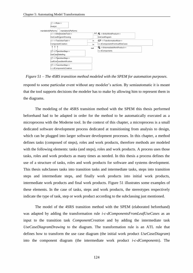
Chapter 5: Automating Model Transformations
124
Figure 51 – The 4SRS transition method modeled with the SPEM for automation purposes.
respond to some particular event without any modeler’s action. By semiautomatic it is meant
that the tool supports decisions the modeler has to make by allowing him to represent them in
the diagrams.
The modeling of the 4SRS transition method with the SPEM this thesis performed
beforehand had to be adapted in order for the method to be automatically executed as a
microprocess with the Moderne tool. In the context of this chapter, a microprocess is a small
dedicated software development process dedicated at transitioning from analysis to design,
which can be plugged into larger software development processes. In this chapter, a method
defines tasks (composed of steps), roles and work products, therefore methods are modeled
with the following elements: tasks (and steps), roles and work products. A process uses those
tasks, roles and work products as many times as needed. In this thesis a process defines the
use of a structure of tasks, roles and work products for software and systems development.
This thesis subclasses tasks into transition tasks and intermediate tasks, steps into transition
steps and intermediate steps, and finally work products into initial work products,
intermediate work products and final work products. Figure 51 illustrates some examples of
these elements. In the case of tasks, steps and work products, the stereotypes respectively
indicate the type of task, step or work product according to the subclassing just mentioned.
The model of the 4SRS transition method with the SPEM (elaborated beforehand)
was adapted by adding the transformation rule i-c-dComponentsFromLeafUseCases as an
input to the transition task ComponentCreation and by adding the intermediate task
UseCaseDiagramDrawing to the diagram. The transformation rule is an ATL rule that
defines how to transform the use case diagram (the initial work product UseCaseDiagram)
into the component diagram (the intermediate work product i-c-dComponents). The

5.3. Automating the 4SRS Transition Method
125
Figure 52 – A use case diagram from the GoPhone.
intermediate task had to be modeled to give the input (initial work product UseCaseDiagram)
to the task that consumes the only initial work product in the model of the 4SRS transition
method with the SPEM, which are the transition task ComponentCreation and the initial work
product UseCaseDiagram. The intermediate task UseCaseDiagramDrawing was needed
since the Moderne tool does not allow creating an input to a task in the context of the task
itself, rather in the context of another task as output of that own task.
This thesis analyzed the model of the 4SRS transition method with the SPEM to
identify the steps that could be automated with the Moderne tool. Table 2 shows that analysis.
Some steps of the 4SRS transition method were concluded to be fully automated with the
Moderne tool whereas others where concluded to be semiautomated or not automated at all.
The automation capability is the ability of a method’s step to be automated with a tool. The
ones concluded to be fully automated with the tool were classified as “Automatic” in terms of
their automation capability, the ones concluded to be semiautomated with the tool were
classified as “Semiautomatic” and the ones concluded to be not automated with the tool
where classified as “Not automatic”. The automatic steps were automated using ATL model-
to-model transformation rules. A semiautomatic step depends on some modeler’s action in
the models by means of the tool before the ATL model-to-model transformation rules
concerning that particular step can be applied. The not automatic steps comprise actions that
are fully performed by the modeler even that they consist of input for the models or for the
information attached to the models, in the tool.
The use case diagram in Figure 52 is used to exemplify the model-to-model
transformations the Moderne tool is able to perform in the context of the 4SRS. The diagram
is based on the GoPhone case study.

Chapter 5: Automating Model Transformations
126
Table 2 – Analysis of the automation capability of the steps from the 4SRS.
4SRS Step/Microstep Automation Capability
Step 1: Component Creation Automatic
Microstep 2.i: Use Case Classification Not automatic (the modeler shall decide each use case’s classification)
Microstep 2.ii: Local Elimination Semiautomatic (the modeler shall tag in the component diagram the components to eliminate or maintain)
Microstep 2.iii: Component Naming Not automatic
Microstep 2.iv: Component Description Not automatic
Microstep 2.v: Component Representation Not automatic (the modeler explicitly relates components in the diagram through Dependency
relationships indicating which component represents others)
Microstep 2.vi: Global Elimination Automatic (based on the Dependency relationships mentioned above in this table)
Microstep 2.vii: Component Renaming Not automatic
Step 3: Component Packaging and Nesting Not automatic
Step 4: Component Association Semiautomatic (partially based on the rules for associating components and partially based on the
modeler’s decision)
Intermediate step 4+1: Filtering and Collapsing Semiautomatic (the collapsing is automatic; the filtering is semiautomatic depending partially on the modeler’s decision to perform refinement and with the automatic exclusion of the components not associated with any
component from the region to refine determined by the modeler)
Intermediate microstep 4+2.i: Deriving Use Cases from Components
Not automatic
Intermediate microstep 4+2.ii: Detailing Use Cases Not automatic
The transformation of the use case diagram in Figure 52 into the corresponding
component diagram was defined in an ATL rule that mostly determines what leaf use cases
are. Leaf use cases are those from which interface components, control components and data
components are generated in step 1 of the 4SRS (Component Creation). The ATL rule
defines that leaf use cases are those that are included by at least one use case and that do not
include any other use case, and those that are not included by any use case and do not include
any use case. The rule also defines some associations between components, and between
components and actors (from the use case diagram). This anticipates part of step 4
(Component Association) to step 1 (Component Creation).
Figure 53 depicts part of the ATL rule that determines the leaf use cases of a use case
diagram. The function srcIncludes() gets all Include relationships whose source is the

5.3. Automating the 4SRS Transition Method
127
helper context UML!UseCase def : isLeaf() : Boolean =
self.srcIncludes()->size() = 0;
Figure 53 – Part of the ATL rule that determines the leaf use cases of a use case diagram.
Figure 54 – The component diagram automatically generated from the use case diagram in
Figure 52.
use case under evaluation. If the use case is not the source of any Include relationship, it
means the use case under evaluation is a leaf use case. The component diagram generated
from the use case diagram in Figure 52 through the ATL rule and the Moderne tool is in
Figure 54.
This thesis defines some well-formedeness rules or constraints in OCL to do what the
following figures illustrate.
A transition task can transform an initial work product into an intermediate work
product or an intermediate work product into an intermediate work product or even an
intermediate work product into a final work product. The OCL code for these constraints is in
Figure 55. Figure 56 shows a validation error signaled with a cross in a transition task that
transforms an intermediate work product into an initial work product.
An intermediate task transforms a final work product into an initial work product. The
OCL code for this constraint is in Figure 57. Figure 58 illustrates a validation error signaled
with a cross in an association between an intermediate task and an initial work product.
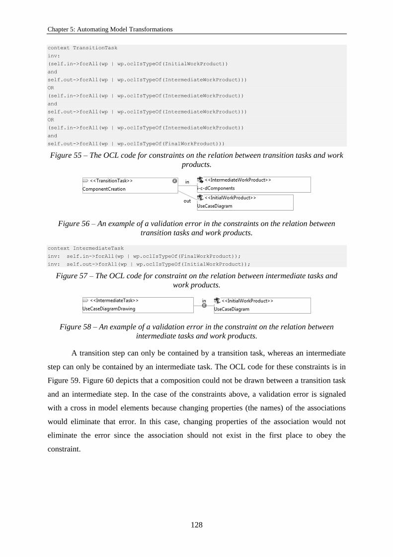
Chapter 5: Automating Model Transformations
128
context TransitionTask
inv:
(self.in->forAll(wp | wp.oclIsTypeOf(InitialWorkProduct))
and
self.out->forAll(wp | wp.oclIsTypeOf(IntermediateWorkProduct)))
OR
(self.in->forAll(wp | wp.oclIsTypeOf(IntermediateWorkProduct))
and
self.out->forAll(wp | wp.oclIsTypeOf(IntermediateWorkProduct)))
OR
(self.in->forAll(wp | wp.oclIsTypeOf(IntermediateWorkProduct))
and
self.out->forAll(wp | wp.oclIsTypeOf(FinalWorkProduct)))
Figure 55 – The OCL code for constraints on the relation between transition tasks and work
products.
Figure 56 – An example of a validation error in the constraints on the relation between
transition tasks and work products.
context IntermediateTask
inv: self.in->forAll(wp | wp.oclIsTypeOf(FinalWorkProduct));
inv: self.out->forAll(wp | wp.oclIsTypeOf(InitialWorkProduct));
Figure 57 – The OCL code for constraint on the relation between intermediate tasks and
work products.
Figure 58 – An example of a validation error in the constraint on the relation between
intermediate tasks and work products.
A transition step can only be contained by a transition task, whereas an intermediate
step can only be contained by an intermediate task. The OCL code for these constraints is in
Figure 59. Figure 60 depicts that a composition could not be drawn between a transition task
and an intermediate step. In the case of the constraints above, a validation error is signaled
with a cross in model elements because changing properties (the names) of the associations
would eliminate that error. In this case, changing properties of the association would not
eliminate the error since the association should not exist in the first place to obey the
constraint.
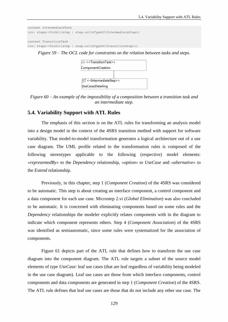
5.4. Variability Support with ATL Rules
129
context IntermediateTask
inv: steps->forAll(step | step.oclIsTypeOf(IntermediateStep))
context TransitionTask
inv: steps->forAll(step | step.oclIsTypeOf(TransitionStep)))
Figure 59 – The OCL code for constraints on the relation between tasks and steps.
Figure 60 – An example of the impossibility of a composition between a transition task and
an intermediate step.
5.4. Variability Support with ATL Rules
The emphasis of this section is on the ATL rules for transforming an analysis model
into a design model in the context of the 4SRS transition method with support for software
variability. That model-to-model transformation generates a logical architecture out of a use
case diagram. The UML profile related to the transformation rules is composed of the
following stereotypes applicable to the following (respective) model elements:
«representedBy» to the Dependency relationship, «option» to UseCase and «alternative» to
the Extend relationship.
Previously, in this chapter, step 1 (Component Creation) of the 4SRS was considered
to be automatic. This step is about creating an interface component, a control component and
a data component for each use case. Microstep 2.vi (Global Elimination) was also concluded
to be automatic. It is concerned with eliminating components based on some rules and the
Dependency relationships the modeler explicitly relates components with in the diagram to
indicate which component represents others. Step 4 (Component Association) of the 4SRS
was identified as semiautomatic, since some rules were systematized for the association of
components.
Figure 61 depicts part of the ATL rule that defines how to transform the use case
diagram into the component diagram. The ATL rule targets a subset of the source model
elements of type UseCase: leaf use cases (that are leaf regardless of variability being modeled
in the use case diagram). Leaf use cases are those from which interface components, control
components and data components are generated in step 1 (Component Creation) of the 4SRS.
The ATL rule defines that leaf use cases are those that do not include any other use case. The

Chapter 5: Automating Model Transformations
130
from u : UML!UseCase (if u.isLeaf() or u.name.startsWith('<<option>>') then u.extend-
>isEmpty() else false endif)
Figure 61 – Part of the ATL rule that applies to a use case diagram: definition of the subset
of source use cases in contexts of variability.
helper context UML!UseCase def : isLeaf() : Boolean =
self.srcIncludes()->size() = 0;
helper context UML!UseCase def : srcIncludes() : Sequence(UML!Include) =
UML!Include.allInstancesFrom('IN')->select(c|c.getSrc()=self);
helper context UML!Include def : getSrc() : UML!UseCase =
self.includingCase;
Figure 62 – Part of the ATL rule that applies to a use case diagram: definition of leaf use
cases regardless of variability.
ATL rule also defines some associations between components, and between components and
actors (from the use case diagram). This anticipates part of step 4 (Component Association) to
step 1 (Component Creation). In the presence of variability, alternative use cases (connected
to each other through Extend relationships stereotyped as «alternative») are considered to be
leaf use cases. Also, «option» use cases are considered to be leaf use cases. The ATL rule
evaluates if a use case owns any Include relationship through the function isLeaf() and
verifies if its name begins with «option». If the use case does not own any Include
relationship or its name begins with «option», then the ATL rule verifies if the use case
does not extend any other use case, which shall be the case. This means the subset of source
use cases the ATL rule considers is composed of the ones returned from the function
isLeaf()simultaneously not owning an Extend relationship (that can be an alternative or a
specialization), as well as those marked with the stereotype «option» simultaneously not
owning an Extend relationship.
Figure 62 shows the implementation of the function isLeaf(). In the context of the
srcIncludes() function, the function allInstancesFrom(‘IN’) gets all instances
of Include relationships from the source model (in this case, the use case diagram). The
function getSrc() gets all including use cases from the use case diagram. If getSrc()
gets no use cases, it means the use case under evaluation is leaf (an including use case cannot
be a leaf use case).
Figure 63 illustrates the part of the ATL rule that creates components, as well as the
associations it defines between those components, both for use cases simultaneously neither
including, nor extending and use cases marked with the stereotype «option» simultaneously
not extending. As previously stated, interface components, control components and data

5.4. Variability Support with ATL Rules
131
ci.name <- u.name.regexReplaceAll('U ', 'C ');
ci.name <- ci.name.regexReplaceAll('}', '.i}');
cc.name <- u.name.regexReplaceAll('U ', 'C ');
cc.name <- cc.name.regexReplaceAll('}', '.c}');
cd.name <- u.name.regexReplaceAll('U ', 'C ');
cd.name <- cd.name.regexReplaceAll('}', '.d}');
ci.package.packagedElement <- ci.package.packagedElement.including(cc);
ci.package.packagedElement <- ci.package.packagedElement.including(cd);
ci.package.packagedElement <- thisModule.createAssociation(ci, cc);
lazy rule createAssociation {
from ClassDst : UML!Component,
ClassSrc : UML!Component
to t : UML!"uml::Association"(
ownedEnd <- dst,
ownedEnd <- src
),
dst : UML!Property
(
name<-'dst',
type<-ClassDst
),
src : UML!Property
(
name<-'src',
type<-ClassSrc
)
}
Figure 63 – Part of the ATL rule that applies to a use case diagram: generation of
components from leaf use cases regardless of variability.
components are generated from leaf use cases and the use cases to which the part of the ATL
rule illustrated in Figure 63 applies are leaf use cases regardless of variability consideration at
the level of use cases. For each of these last mentioned use cases an interface component
(ci), a control component (cc) and a data component (cd) are generated. After that, both the
control component and the data component are packaged in the same package as the interface
component.
This thesis also proposes to extend step 4 of the 4SRS with a rule for the association
of components originated from use cases in general (regardless of variability consideration),
from alternative use cases, and from specialization use cases and the use cases they
specialize. An interface component shall be associated with the corresponding control
component, both originated from the same use case. In presence of variability, components
shall be associated with each other and with actors according to the following rules. An
interface component generated from a specialization use case shall be associated with the
interface component generated from the use case it specializes, as well as a control

Chapter 5: Automating Model Transformations
132
if(u.hasExtend() and u.isLeaf())
{
for(e in u.getExtends())
{
usecase<-e.extension;
if(usecase.isLeaf())
{
compi <- thisModule.createComp(usecase);
compi.name <- compi.name.regexReplaceAll('U ', 'C ');
compi.name <- compi.name.regexReplaceAll('}', '.i}');
ci.package.packagedElement <-
ci.package.packagedElement.including(compi);
compc <- thisModule.createComp(usecase);
compc.name <- compc.name.regexReplaceAll('U ', 'C ');
compc.name <- compc.name.regexReplaceAll('}', '.c}');
ci.package.packagedElement <-
ci.package.packagedElement.including(compc);
if(e.name <> '<<alternative>>')
{
ci.package.packagedElement <-
thisModule.createAssociation(ci, compi);
ci.package.packagedElement <-
thisModule.createAssociation(cc, compc);
}
else
{
for(assoc in u.associations())
{
if(assoc.getSrc().oclIsTypeOf(UML!Actor))
{
actor <- assoc.getSrc();
ci.package.packagedElement <-
thisModule.copyAssociation(actor, compi);
}
if(assoc.getDst().oclIsTypeOf(UML!Actor))
{
actor <- assoc.getDst();
ci.package.packagedElement <-
thisModule.copyAssociation(actor, compi);
}
}
}
ci.package.packagedElement <-
thisModule.createAssociation(compi, compc);
compd <- thisModule.createComp(usecase);
compd.name <- compd.name.regexReplaceAll('U ', 'C ');
compd.name <- compd.name.regexReplaceAll('}', '.d}');
ci.package.packagedElement <-
ci.package.packagedElement.including(compd);
}
}
}

5.4. Variability Support with ATL Rules
133
else
{
for( assoc in u.getParent())
{
if(assoc.getSrc().oclIsTypeOf(UML!Actor))
{
actor <- assoc.getSrc();
ci.package.packagedElement <-
thisModule.copyAssociation(actor, ci);
}
if(assoc.getDst().oclIsTypeOf(UML!Actor))
{
actor <- assoc.getDst();
ci.package.packagedElement <-
thisModule.copyAssociation(actor, ci);
}
}
}
Figure 64 – Part of the ATL rule that applies to a use case diagram.
component generated from a specialization use case shall be associated with the control
component generated from the use case it specializes. An interface component shall be
associated with the actor of the use case that originated the component. An actor associated
with a use case for which there is an alternative shall also be associated with the interface
component generated from the use case that represents the alternative.
The function createAssociation in Figure 63 creates an association between
the interface component and the control component. Considering the possibility of data
components representing each other, the ATL rule does not generates a data component for
every leaf use case regardless of variability being considered.
The part of the ATL rule that defines how to transform the use case diagram into the
component diagram and considers the subset of source use cases simultaneously neither
including, nor extending and source use cases marked with the stereotype «option»
simultaneously not extending starts by evaluating that subset of source use cases with the first
two functions in Figure 64: hasExtend() and isLeaf().
For each of the source use cases in the just mentioned subset, the function
hasExtend() in Figure 65 checks if it is an extended use case.

Chapter 5: Automating Model Transformations
134
helper context UML!UseCase def : hasExtend() : Boolean =
UML!Extend.allInstancesFrom('IN')-> exists(st| st.extendedCase = self);
Figure 65 – Part of the ATL rule that applies to a use case diagram: the hasExtend()
function.
helper context UML!UseCase def : getExtends() : Sequence(UML!Extend) =
UML!Extend.allInstancesFrom('IN')-> select(st| st.extendedCase = self);
Figure 66 – Part of the ATL rule that applies to a use case diagram: the getExtends()
function.
The combination of the hasExtend() function with the isLeaf() function
equals considering use cases simultaneously not including, not extending and extended. This
means these use cases are leaf and have at least one alternative to them.
The ATL rule targets each of the leaf use cases from the use case diagram that have at
least one alternative to them with the function getExtends(). In the context of that
function, in Figure 66, the function allInstancesFrom(‘IN’) gets all instances of
Extend relationships from the use case diagram. The function getExtends() gets all
Extend relationships from the use case diagram of which the targeted use case is the extended
use case.
For every use case in the diagram that is leaf (not an including use case), not an
extending use case and has at least one alternative to it, the ATL rule accesses each of the
Extend relationships targeted at it. For each of those relationships, the ATL rule gets the
extending use case and checks if that is not an including use case. If that is the case, then the
ATL rule creates, from the extending use case, an interface component (compi) and a
control component (compc) and packages them in the same package as the components
previously created for the extended use case.
In the context of each Extend relationship just mentioned, the ATL rule verifies if it is
an «alternative». If that is not the case, it means it is a specialization relationship
(relationship stereotyped as «specialization») and the ATL rule creates an association
between the interface component generated from the extended use case and the interface
component generated from the extending use case, as well as an association between the
control component generated from the extended use case and the control component
generated from the extending use case.

5.4. Variability Support with ATL Rules
135
helper context UML!UseCase def : associations() : Sequence(UML!Association) =
UML!Association.allInstancesFrom('IN')->select(c|c.getSrc()=self or c.getDst()=self);
helper context UML!Association def : getSrc() : UML!Element =
self.ownedEnd->select(c | c.name = 'src')->first();
helper context UML!Association def : getDst() : UML!Element =
self.ownedEnd->select(c | c.name = 'dst')->first();
Figure 67 – Part of the ATL rule that applies to a use case diagram: the associations()
function.
lazy rule copyAssociation {
from ClasseSrc : UML!Element,
ClasseDst : UML!Component
to t : UML!"uml::Association"(
ownedEnd <- dst,
ownedEnd <- src
),
dst : UML!Property
(
name<-'dst',
type<-ClasseDst
),
src : UML!Property
(
name<-'src',
type<-ClasseSrc
)
}
Figure 68 – Part of the ATL rule that applies to a use case diagram: generation of
associations between interface components and actors in contexts of alternative variability
(variability related to alternative relationships, which are stereotyped as «alternative»).
Again in the context of each Extend relationship just mentioned, if it is an
«alternative», the ATL rule gets all associations of which the leaf extended use case is
the source or the destination, as Figure 67 demonstrates.
For each of those associations, the ATL rule checks if the source is an UML element
of type Actor. If it is, then it creates an association between the actor and the interface
component generated from the extending use case. After that, the ATL rule performs the
same for the destination of each of those associations (it creates an association between the
actor and the interface component generated from the extended use case). Figure 68 depicts
the creation of these associations.
Still for every use case in the diagram that is leaf, not an extending use case and has at
least one alternative to it, the ATL rule creates an association between the interface
component generated from the extending use case and the control component generated from
the extending use case. Then the ATL rule creates a data component for the extending use
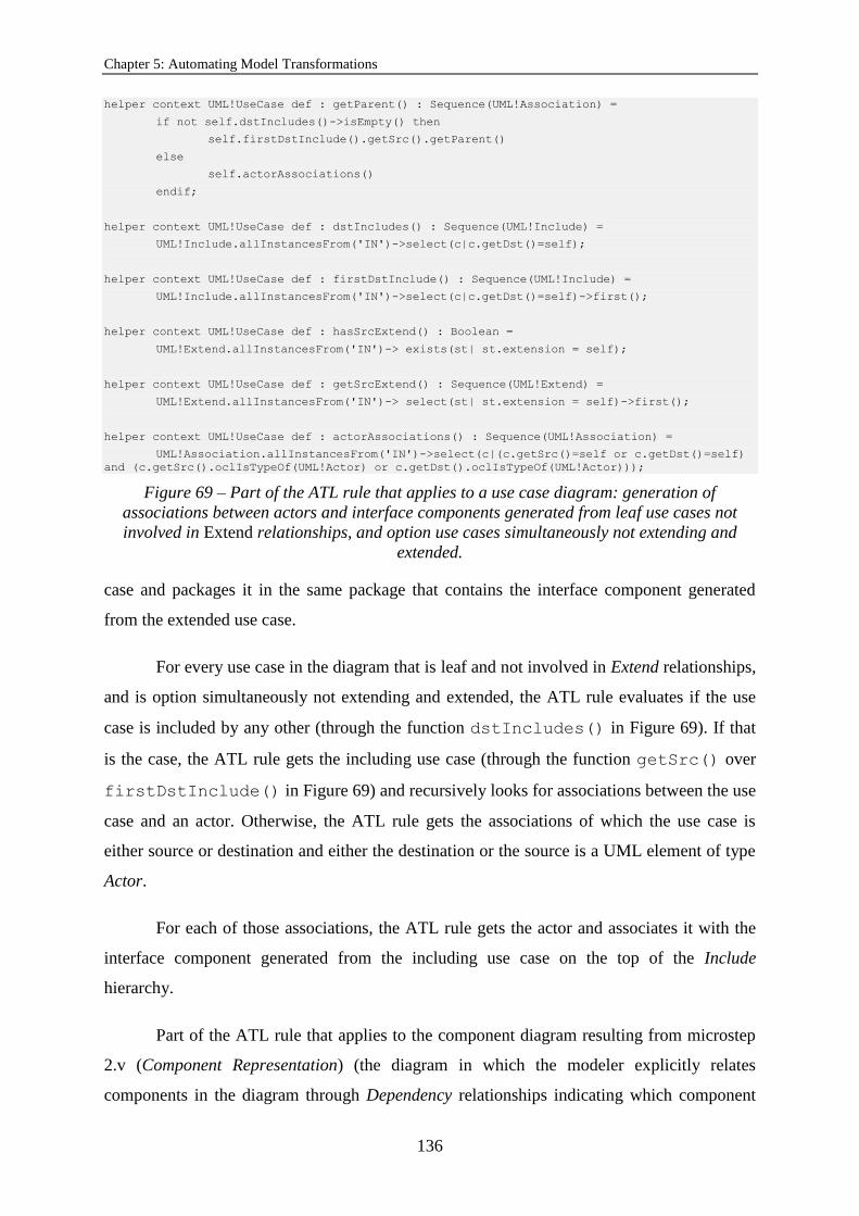
Chapter 5: Automating Model Transformations
136
helper context UML!UseCase def : getParent() : Sequence(UML!Association) =
if not self.dstIncludes()->isEmpty() then
self.firstDstInclude().getSrc().getParent()
else
self.actorAssociations()
endif;
helper context UML!UseCase def : dstIncludes() : Sequence(UML!Include) =
UML!Include.allInstancesFrom('IN')->select(c|c.getDst()=self);
helper context UML!UseCase def : firstDstInclude() : Sequence(UML!Include) =
UML!Include.allInstancesFrom('IN')->select(c|c.getDst()=self)->first();
helper context UML!UseCase def : hasSrcExtend() : Boolean =
UML!Extend.allInstancesFrom('IN')-> exists(st| st.extension = self);
helper context UML!UseCase def : getSrcExtend() : Sequence(UML!Extend) =
UML!Extend.allInstancesFrom('IN')-> select(st| st.extension = self)->first();
helper context UML!UseCase def : actorAssociations() : Sequence(UML!Association) =
UML!Association.allInstancesFrom('IN')->select(c|(c.getSrc()=self or c.getDst()=self)
and (c.getSrc().oclIsTypeOf(UML!Actor) or c.getDst().oclIsTypeOf(UML!Actor)));
Figure 69 – Part of the ATL rule that applies to a use case diagram: generation of
associations between actors and interface components generated from leaf use cases not
involved in Extend relationships, and option use cases simultaneously not extending and
extended.
case and packages it in the same package that contains the interface component generated
from the extended use case.
For every use case in the diagram that is leaf and not involved in Extend relationships,
and is option simultaneously not extending and extended, the ATL rule evaluates if the use
case is included by any other (through the function dstIncludes() in Figure 69). If that
is the case, the ATL rule gets the including use case (through the function getSrc() over
firstDstInclude() in Figure 69) and recursively looks for associations between the use
case and an actor. Otherwise, the ATL rule gets the associations of which the use case is
either source or destination and either the destination or the source is a UML element of type
Actor.
For each of those associations, the ATL rule gets the actor and associates it with the
interface component generated from the including use case on the top of the Include
hierarchy.
Part of the ATL rule that applies to the component diagram resulting from microstep
2.v (Component Representation) (the diagram in which the modeler explicitly relates
components in the diagram through Dependency relationships indicating which component

5.4. Variability Support with ATL Rules
137
from src : UML!Component(if thisModule.allModelElements('IN')->includes(src) then
if
src.name.split('(?s)e(.+)[cd]}').size() = 1 then
src.isRepresented()
else
true
endif
else false endif)
helper context UML!Component def : isRepresented() : Boolean =
self.clientDependency->exists(dep|dep.isStereotyped('«representedBy»'));
helper context UML!UseCase def : isStereotyped(stereotype : String) : Boolean =
self.getAppliedStereotypes()->exists(c|c.name = stereotype);
Figure 70 – Part of the ATL rule that applies to the component diagram resulting from
microstep 2.v of the 4SRS.
represents others) to generate the component diagram resulting from microstep 2.vi (Global
Elimination) is going to be presented next.
Since UML2 Tools [108] (the editor of UML models the Moderne tool uses) does not
allow forbidding the modeler from drawing a «representedBy» Dependency relationship from
a component that cannot be represented by any other, the rules for the global elimination of
components previously mentioned in this section can only be applied when applying the ATL
rule just mentioned.
The next ATL rule automatically performs the transformation of 4SRS’ microstep 2.vi
(Global Elimination). Based on the Dependency relationships the modeler used to explicitly
relate components in the diagram that represent others, this ATL rule (shown partly in Figure
70) takes the name of a component in the source component diagram and evaluates whether
the component shall be copied to the target component diagram or not. If the component’s
name is from a control or data component involved in an Extend relationship, the ATL rule
evaluates if the component is represented by any other (owning at least one Dependency
relationship tagged with the stereotype «representedBy»). If that is the case, the ATL rule
does not maintain the component in the component diagram resulting from this
transformation. The component’s name is evaluated with a split, which is determined by a
regular expression ((?s)e(.+)[cd]}). e represents the character e, (.+) represents one
or more characters (including line terminators, which is determined by the embedded flag
(?s) that enables the DOTALL mode) and [cd]} represents either the characters c} or d}.
If the source component is the client of at least one Dependency relationship stereotyped as
«representedBy», then the ATL rule considers it to be represented by at least another
component (this is achieved through the function isRepresented()). Since UML2 Tools

Chapter 5: Automating Model Transformations
138
does not allow the stereotype «representedBy» on Dependency relationships, the ATL rule
looks for the stereotype in the component’s name (c.name = stereotype).
5.5. Conclusions
The SPEM is a software and systems development process modeling language.
Transition methods describe how to transform artifacts originally produced within a certain
discipline of a large software development process into artifacts from another discipline of
such a process. Some transition methods are targeted at moving from the analysis to the
design of software. The 4SRS is a method that allows moving from the analysis to the design
of software. In the case of the 4SRS, the analysis model (a UML use case diagram) influences
architectural decisions that originate a design model (a UML component diagram, the first
technical artifact to initiate the design of the system).
The work reported in this chapter was to formalize transition methods as small
dedicated software development processes that can be plugged into larger software
development processes. In that sense, the SPEM was extended through metamodeling
techniques for defining a visual language to model transition methods and formalizing small
dedicated (at transitioning from the analysis to the design of) software development processes
(such as the 4SRS). The 4SRS modeled as a method content from the SPEM can be the basis
for formalizing it as a small software development process dedicated at transitioning from the
analysis to the design of software, which can be plugged into larger software development
processes.
This chapter presents some models drawn (in the context of the 4SRS) with the visual
language this thesis defined by extending the SPEM: the method content model for the 4SRS,
a process model with instances from the process structure metamodel, an activity detail
model of the 4SRS microprocess structure and a workflow model of the 4SRS microprocess
behavior.
This chapter describes the automation of a transition method, using the 4SRS method
modeled with the SPEM as the case study. This thesis reports the adaptation of the Moderne
tool to automate the generation of logical architectures through model transformations
defined with the ATL language. This thesis defines some well-formedeness rules or
constraints in OCL to validate the models of the 4SRS transition method with the SPEM.

5.5. Conclusions
139
The SPEM model of the 4SRS transition method elaborated beforehand was adapted
for automation purposes. For instance a transformation rule was added to the diagram.
The OCL constraints on the models of the 4SRS transition method with the SPEM
established the well-formedeness of the relations between transition tasks and work products,
between intermediate tasks and work products, and between tasks and steps (all of these are
elements for the modeling of methods). The violation of the constraints on those relations is
tagged in the model through validation errors.
This chapter also reported the transformation rules to automate some steps of the
transition from use cases to a logical architecture, both diagrams supporting the
representation of variability. The metamodel this thesis extended represents a metamodeling
approach, which means the approach in this thesis is in concordance with the suggestion of
Brown, et al. stating that if a metamodel is ellaborated, transformations between models
using automation tools are facilitated [65].
The method to refine logical architectures with variability support prompted by
chapter 3 has been automated with the work reported in this chapter.

Chapter 5: Automating Model Transformations
140

141
This last chapter is devoted to showing the way the contributions of this thesis addressed the research goals
pointed out in Chapter 1, to presenting the list of publications this thesis produced, and to providing
suggestions to continue developing and applying this research.
6. Conclusions
6.1. Discussion
Research Contributions
Chapter 3 reflected upon the support of the UML metamodel for the functional
refinement of use case diagrams. It concluded that the «include» relationship is not adequate
for that purpose and proposed an extension to the UML metamodel to bridge that gap with a
new relationship: the «refine» relationship. Chapter 3 also proposed a systematization of use
case variability modeling, as well as an extension to the UML metamodel in order to model
variability in use case diagrams according to that systematization. This chapter proposed to
represent variability in use case diagrams through «extend» relationships and stereotypes. It
considered that the «extend» relationship is adequate for modeling alternatives and
specializations, and a stereotype applicable to use cases for modeling options. This chapter
proposed the stereotypes «alternative», «specialization» and «option» to distinguish the three
variability types it proposed. It also proposed the stereotype «variant» to mark use cases at
higher levels of abstraction before they are realized into alternatives or specializations. The
stereotypes «alternative» and «specialization» were recommended to be applicable to the
«extend» relationship for modeling alternatives and specializations, respectively, and the

Chapter 6: Conclusions
142
stereotype «option» to mark use cases that represent options. Chapter 3 also argued about the
implications of functionally refining use cases when variability is represented in use case
diagrams with use cases connected through «extend» relationships. The approach of this
chapter to use case modeling with support for refinement and variability was illustrated with
the GoPhone case study. Chapter 3 provided for the following research contributions:
Research contribution 1: an extension to the UML metamodel for the functional
refinement of use case diagrams.
Research contribution 2: an extension to the UML metamodel for variability
modeling in use case diagrams.
These contributions addressed the following research goals, pointed out in Chapter 1:
Research goal 1: providing specific guidelines on how to conduct the activity of use
case modeling with support for functional refinement.
Research goal 2: providing specific guidelines on how to conduct the activity of use
case modeling with support for both functional refinement and software variability.
By representing variability in use case diagrams, chapter 3 provided for variability
support in the logical architectures generated with the execution of the 4SRS transition
method over those use case diagrams. Chapter 3 formalized use case refinement, which is
relevant for the preparation of the recursive method’s execution, as well as it provided for
guidelines to determine the use cases that will be the input for the method’s execution
(recursive or not) and exposed the implications of executing the method itself when
variability is considered in use cases. The extension of the 4SRS proposed in chapter 3
included the formalization of filtering and collapsing techniques applicable to the logical
architectures delivered by the method’s execution (recursive or not) and the formalization of
the transformation from components to use cases in order to prepare the recursive execution
of the method. Chapter 3 provided for the following research contributions:
Research contribution 3: guidelines to determine the use cases that will be the input
for the 4SRS’ execution (recursive or not) when variability is considered in use cases.

6.1. Discussion
143
Research contribution 4: guidelines for the execution of the 4SRS when variability is
considered in use cases.
Research contribution 5: extension of the 4SRS with filtering and collapsing
techniques applicable to the logical architectures delivered by the method’s execution
(recursive or not).
Research contribution 6: formalization of the transformation from components to
use cases in order to prepare the recursive execution of the 4SRS.
These contributions addressed the following research goal, pointed out in Chapter 1:
Research goal 3: supporting the refinement of logical software architectures with
variability support by extending a method applicable for modeling those architectures (the
4SRS).
Chapter 4 concluded that a procedural referential such as the RUP is important to
classify patterns, mainly because it gives the classification a notion of software development
process, therefore, it proposed a multilevel and multistage pattern classification. That
classification provides for the knowledge of the moment from the software development
process in which to use specific kinds of patterns. The foundation for the model
transformation the 4SRS conducts is given the classification chapter 4 reported of a specific
pattern (the MVC) and its incorporation in the structure of the logical architectures the 4SRS
generates. Chapter 4 provided for the following research contribution:
Research contribution 7: multilevel and multistage software development pattern
classification based on the RUP and the classification of some software development
patterns.
This contribution addressed the following research goal, pointed out in Chapter 1:
Research goal 4: classifying software patterns according to a multilevel and
multistage pattern classification based on the software development process to justify the
pattern used for the model transformation the 4SRS guides.

Chapter 6: Conclusions
144
Chapter 5 formalized a transition method (the 4SRS) as a small dedicated (at
transitioning from the analysis to the design of) software development process that can be
plugged into larger software development processes. For that purpose, chapter 5 extended the
SPEM through metamodeling techniques for defining a visual language to model transition
methods. Then, it modeled the 4SRS as a method content from the SPEM. Chapter 5 also
elaborated on the automation of transition methods by means of a case study with the 4SRS
method modeled with the SPEM and automated with the Moderne tool, which was adapted
for the purpose. In the context of the Moderne tool, the 4SRS model transformations were
defined with the ATL language, as well as some well-formedeness rules or constraints were
defined with OCL to validate the models of the 4SRS transition method with the SPEM.
Finally, chapter 5 addressed the transformation rules the Moderne tool used to automate some
steps of the 4SRS with support for variability. Chapter 5 provided for the following research
contributions:
Research contribution 8: visual language to model transition methods by means of
an extension to the SPEM.
Research contribution 9: model of the 4SRS as a method content from the SPEM.
Research contribution 10: the Moderne tool adapted to automate the 4SRS
transition method modeled with the SPEM, including ATL model transformation rules for the
execution of the 4SRS with support for variability and OCL constraints to validate the models
of the 4SRS with the SPEM.
These contributions addressed the following research goals, pointed out in Chapter 1:
Research goal 5: exploring the particularities of modeling transition methods (like
the 4SRS) to formalize them as small dedicated software development processes.
Research goal 6: exemplifying the SPEM modeling of a transition method like the
4SRS as a way to study the benefits of the automatic execution of transition methods as small
dedicated software development processes.
Research goal 7: reflecting on the impact of variability over the automation of
transition methods (like the 4SRS) modeled with SPEM.

6.2. Future Work
145
Publications
This thesis produced some research publications, namely:
1) S. Azevedo, et al., "On the Refinement of Use Case Models with Variability Support,"
Innovations in Systems and Software Engineering, vol. 8, pp. 51-64, 2012;
2) S. Azevedo, et al., "On the Use of Model Transformations for the Automation of the
4SRS Transition Method " presented at the 10th International Workshop on
System/Software Architectures (IWSSA 2012), Gdańsk, Poland, 2012;
3) S. Azevedo, et al., "Systematic Use of Software Development Patterns through a
Multilevel and Multistage Classification," in Model-Driven Domain Analysis and
Software Development: Architectures and Functions, J. Osis and E. Asnina, Eds., ed
Hershey: IGI Global, 2011, pp. 304-333;
4) S. Azevedo, et al., "Support for Variability in Use Case Modeling with Refinement,"
presented at the 7th International Workshop on Model-Based Methodologies for
Pervasive and Embedded Software (MOMPES 2010), Antwerp, Belgium, 2010;
5) S. Azevedo, et al., "The UML «extend» Relationship as Support for Software
Variability," presented at the 14th International Software Product Line Conference (SPLC
2010), Jeju Island, South Korea, 2010;
6) S. Azevedo, et al., "The UML «include» Relationship and the Functional Refinement of
Use Cases," presented at the 36th Euromicro Conference on Software Engineering and
Advanced Applications (SEAA 2010), Lille, France, 2010;
7) S. Azevedo, et al., "Refinement of Software Product Line Architectures through
Recursive Modeling Techniques," presented at the 8th International Workshop on
System/Software Architectures (IWSSA 2009), Vilamoura, Portugal, 2009;
8) S. Azevedo, et al., "Multistage Model Transformations in Software Product Lines,"
presented at the Simpósio para Estudantes de Doutoramento em Engenharia de Software
(SEDES 2009), Porto, Portugal, 2009.
6.2. Future Work
The most obvious work to conduct in the future as an extension of this thesis is to
define or formalize the support for refinement and variability in other perspectives over
software systems or families of software systems development.
Future work concerning the software patterns in the context of the software
development process involves studying how patterns evolve over the time of that process.
This evolution demands for the comprehension of the relationships between software patterns
(especially those positioned at consecutive stages). It also demands for the analysis of how
time implies that software patterns are associated with each other in a chain. The gap between
patterns used at different stages shall be bridged in order to have a complete multistage

Chapter 6: Conclusions
146
software development process that contemplates different artifacts (software patterns and
other artifacts like use cases, component diagrams and others). In fact software patterns used
at different stages solve the same problem at different levels of abstraction.
Software patterns may be used to detail logical software system architectures
(expressed through component diagrams). As software patterns are normally presented in
class diagrams, the detailing of those architectures requires knowing how to apply the
concept of class to the concept of (logical) component.
The consideration of software patterns within the context of the software development
process claims for the specialization of the actors who intervene in that process with specific
roles during the adoption of those patterns. It is relevant to study the impacts of other
software development processes (besides the RUP) in the proposed pattern classification.
Developing software product lines with software patterns (and other artifacts) may
have some particular implications. Some variability mechanisms may have to be taken into
account in software patterns. The use of those mechanisms may be constrained to a specific
level of the OMG modeling infrastructure (the M2-level) and to specific pattern types. It may
be necessary to define all the possible M2-level concepts (e.g. classes, attributes, operations)
and/or the values of those concepts (e.g. class names, class attributes, class operations) as
well as the application of all of them to all or some of the product line’s members. The whole
matter with software product lines and software patterns may mainly lie on the instantiation
of M2-level artifacts at the M1-level.
Finally it is important to determine which software patterns may and shall be made
available in modeling infrastructures (either through libraries of software pattern metamodels
or models, or through domain-specific languages).
In terms of future work concerned with the automation of transition methods (like the
4SRS), it is planned to assess the efficiency of this thesis’ approach by adopting the Moderne
tool to apply the 4SRS transition method in a real industrial project. It is also planned to
include the approach of this thesis to the refinement of logical architectures with the 4SRS
transition method in the Moderne tool, as well as conducting a broader case study on the use
of the Moderne for the same purpose and validating that approach with software metrics.

147
References [1] OMG. (2009). Unified Modeling Language: Superstructure - version 2.2. Available:
http://www.omg.org
[2] J. Greenfield and K. Short, Software Factories: Assembling Applications with
Patterns, Models, Frameworks, and Tools. Hoboken, New Jersey: Wiley, 2004.
[3] J. Greenfield and K. Short, "Software Factories: Assembling Applications with
Patterns, Models, Frameworks and Tools," presented at the 18th Annual ACM
SIGPLAN Conference on Object-Oriented Programming, Systems, Languages and
Applications (OOPSLA 2003), Anaheim, California, USA, 2003.
[4] J. M. Fernandes, et al., "A Demonstration Case on the Transformation of Software
Architectures for Service Specification," presented at the 5th IFIP Working
Conference on Distributed and Parallel Embedded Systems (DIPES 2006), Braga,
Portugal, 2006.
[5] R. J. Machado, et al., "Refinement of Software Architectures by Recursive Model
Transformations," presented at the 7th International Conference on Product Focused
Software Process Improvement (PROFES 2006), Amsterdam, The Netherlands, 2006.
[6] R. J. Machado, et al., "Transformation of UML Models for Service-Oriented Software
Architectures," presented at the 12th IEEE International Conference and Workshops
on the Engineering of Computer-Based Systems (ECBS 2005), Greenbelt, Maryland,
USA, 2005.
[7] D. Muthig, et al., "GoPhone - A Software Product Line in the Mobile Phone
Domain," Fraunhofer IESE, IESE-Report No. 025.04/EMarch 5 2004.
[8] F. Buschmann, et al., Pattern-Oriented Software Architecture: A System of Patterns.
Hoboken, New Jersey: Wiley, 1996.
[9] P. Kruchten, The Rational Unified Process: An Introduction. Upper Saddle River,
New Jersey: Addison-Wesley, 2000.
[10] L. Balmelli, et al., "Model-Driven Systems Development," IBM Systems Journal, vol.
45, pp. 569-585, 2006.
[11] C. Atkinson and T. Kühne, "Model-Driven Development: A Metamodeling
Foundation," IEEE Software, vol. 20, pp. 36-41, 2003.
[12] OMG. (2008). Software & Systems Process Engineering Meta-Model Specification -
version 2.0. Available: http://www.omg.org
[13] I. Vessey, et al., "Research in Information Systems: An Empirical Study of Diversity
in the Discipline and Its Journals," Journal of Management Information Systems, vol.
9, pp. 129-174, 2002.
[14] R. A. Gomes, et al., "Moderne: Model Driven Process Centered Software Engineering
Environment," presented at the 2nd Congresso Brasileiro de Software: Teoria e
Prática (CBSoft 2011), São Paulo, Brasil, 2011.
[15] B. Paech and B. Rumpe, "A New Concept of Refinement used for Behaviour
Modelling with Automata," presented at the 2nd International Symposium of Formal
Methods Europe (FME 1994), Barcelona, Spain, 1994.

148
[16] D. A. C. Quartel, et al., "An Engineering Approach towards Action Refinement,"
presented at the 5th IEEE Workshop on Future Trends of Distributed Computing
Systems (FTDCS 1995), Chenju, Korea, 1995.
[17] R. Darimont and A. v. Lamsweerde, "Formal Refinement Patterns for Goal-Driven
Requirements Elaboration," presented at the 4th Symposium on the Foundations of
Software Engineering (FSE-4), San Francisco, California, USA, 1996.
[18] M. Schrefl and M. Stumptner, "Behavior Consistent Refinement of Object Life
Cycles," presented at the 16th International Conference on Conceptual Modeling (ER
1997), Los Angeles, California, USA, 1997.
[19] B. Mikolajczak and Z. Wang, "Conceptual Modeling of Concurrent Systems through
Stepwise Abstraction and Refinement Using Petri Net Morphisms," presented at the
22nd International Conference on Conceptual Modeling (ER 2003), Chicago, Illinois,
USA, 2003.
[20] D. Batory, et al., "Scaling Step-Wise Refinement," IEEE Transactions on Software
Engineering, vol. 30, pp. 355-371, June 2004.
[21] S. S.-s. Cherfi, et al., "Use Case Modeling and Refinement: A Quality-Based
Approach," presented at the 25th International Conference on Conceptual Modeling
(ER 2006), Tucson, Arizona, USA, 2006.
[22] A. Cockburn, Writing Effective Use Cases. Upper Saddle River, New Jersey:
Addison-Wesley, 2000.
[23] C. Pons and R.-D. Kutsche, "Traceability Across Refinement Steps in UML
Modeling," presented at the 3rd UML Workshop in Software Model Engineering
(WiSME 2004), Lisbon, Portugal, 2004.
[24] M. Eriksson, et al., "Software Product Line Modeling Made Practical,"
Communications of the ACM, vol. 49, pp. 49-53, 2006.
[25] A. Egyed, et al., "Software Connectors and Refinement in Family Architectures,"
presented at the 3rd International Workshop on Development and Evolution of
Software Architectures for Product Families (IWSAPF-3), Las Palmas de Gran
Canaria, Spain, 2000.
[26] H. Gomaa, Designing Software Product Lines with UML: From Use Cases to Pattern-
Based Software Architectures. Upper Saddle River, New Jersey: Addison-Wesley,
2004.
[27] M. Fowler, UML Distilled: A Brief Guide to the Standard Object Modeling Language.
Upper Saddle River, New Jersey: Addison-Wesley, 2004.
[28] A. Bragança and R. J. Machado, "Extending UML 2.0 Metamodel for
Complementary Usages of the «extend» Relationship within Use Case Variability
Specification," presented at the 10th International Software Product Line Conference
(SPLC 2006), Baltimore, Maryland, USA, 2006.
[29] A. Bragança and R. J. Machado, "Deriving Software Product Line's Architectural
Requirements from Use Cases: An Experimental Approach," presented at the 2nd
International Workshop on Model-Based Methodologies for Pervasive and Embedded
Software (MOMPES 2005), Rennes, France, 2005.
[30] J. Bayer, et al., "Consolidated Product Line Variability Modeling," in Software
Product Lines - Research Issues in Engineering and Management, T. Käköla and J. C.
Duenas, Eds., ed Berlin Heidelberg: Springer-Verlag, 2006, pp. 195-241.
149
[31] I. John and D. Muthig, "Tailoring Use Cases for Product Line Modeling," presented at
the International Workshop on Requirements Engineering for Product Lines (REPL
2002), Essen, Germany, 2002.
[32] I. John and D. Muthig, "Product Line Modeling with Generic Use Cases," presented
at the Workshop on Techniques for Exploiting Commonality Through Variability
Management, San Diego, California, USA, 2002.
[33] K. Kang, et al., "Feature-Oriented Domain Analysis (FODA) Feasibility Study,"
Software Engineering Institute, Carnegie Mellon University, Technical Report1990.
[34] F. Bachmann, et al., "A Meta-model for Representing Variability in Product Family
Development," presented at the 5th International Workshop on Product-Family
Engineering (PFE-5), Siena, Italy, 2004.
[35] S. Bühne, et al., "Modelling Requirements Variability across Product Lines,"
presented at the 13th IEEE International Conference on Requirements Engineering
(RE 2005), Paris, France, 2005.
[36] J. Coplien, et al., "Commonality and Variability in Software Engineering," IEEE
Software, vol. 15, pp. 37-45, 1998.
[37] T. v. d. Maßen and H. Lichter, "Modeling Variability by UML Use Case Diagrams,"
presented at the International Workshop on Requirements Engineering for Product
Lines (REPL 2002), Essen, Germany, 2002.
[38] H. Gomaa and M. E. Shin, "Multiple-View Modelling and Meta-Modelling of
Software Product Lines," Institution of Engineering and Technology Software, vol. 2,
pp. 94-122, 2008.
[39] H. Gomaa and M. E. Shin, "A Multiple-View Meta-modeling Approach for
Variability Management in Software Product Lines," presented at the 8th International
Conference on Software Reuse (ICSR-8), Madrid, Spain, 2004.
[40] H. Gomaa and E. M. Olimpiew, "Managing Variability in Reusable Requirement
Models for Software Product Lines," presented at the 10th International Conference
on Software Reuse (ICSR-10), Beijing, China, 2008.
[41] D. L. Webber and H. Gomaa, "Modeling Variability in Software Product Lines with
the Variation Point Model," Science of Computer Programming, vol. 53, pp. 305-331,
2004.
[42] G. Halmans and K. Pohl, "Communicating the Variability of a Software-Product
Family to Customers," Software and Systems Modeling, vol. 2, pp. 15-36, 2003.
[43] K. Pohl, et al., Software Product Line Engineering: Foundations, Principles, and
Techniques. Berlin Heidelberg: Springer-Verlag, 2005.
[44] S. Salicki and N. Farcet, "Expression and Usage of the Variability in the Software
Product Lines," presented at the 4th International Workshop on Product Family
Engineering (PFE-4), Bilbao, Spain, 2002.
[45] J. Bosch, et al., "Variability Issues in Software Product Lines," presented at the 4th
International Workshop on Product Family Engineering (PFE-4), Bilbao, Spain, 2002.
[46] T. Ziadi, et al., "Towards a UML Profile for Software Product Lines," presented at the
5th International Workshop on Product-Family Engineering (PFE-5), Siena, Italy,
2004.

150
[47] A. J. H. Simons, "Use Cases Considered Harmful," presented at the 29th Conference
on Technology of Object-Oriented Languages and Systems (TOOLS Europe 1999),
Nancy, France, 1999.
[48] R. Heldal, "Use Cases are more than System Operations," presented at the 2nd
International Workshop on Use Case Modeling (WUsCaM 2005), Montego Bay,
Jamaica, 2005.
[49] F. Buschmann, et al., Pattern-Oriented Software Architecture: On Patterns and
Pattern Languages. Hoboken, New Jersey: Wiley, 2007.
[50] E. Gamma, et al., Design Patterns: Elements of Reusable Object-Oriented Software.
Upper Saddle River, New Jersey: Addison-Wesley, 1995.
[51] K. Beck, Implementation Patterns. Upper Saddle River, New Jersey: Addison-
Wesley, 2008.
[52] H.-E. Eriksson and M. Penker, Business Modeling With UML: Business Patterns at
Work. Hoboken, New Jersey: Wiley, 2000.
[53] W. F. Tichy, "A Catalogue of General-Purpose Software Design Patterns," presented
at the 23rd Technology of Object-Oriented Languages and Systems (TOOLS-23),
Santa Barbara, California, USA, 1997.
[54] W. Pree, Design Patterns for Object-Oriented Software Development. Upper Saddle
River, New Jersey: Addison-Wesley, 1995.
[55] W. Zimmer, "Relationships between Design Patterns," in Pattern Languages of
Program Design, J. O. Coplien and D. C. Schmidt, Eds., ed Upper Saddle River, New
Jersey: Addison-Wesley, 1995, pp. 345-364.
[56] D. Schmidt, et al., Pattern-Oriented Software Architecture: Patterns for Concurrent
and Networked Objects. Hoboken, New Jersey: Wiley, 2000.
[57] M. Kircher and P. Jain, Pattern-Oriented Software Architecture: Patterns for
Resource Management. Hoboken, New Jersey: Wiley, 2004.
[58] F. Buschmann, et al., Pattern-Oriented Software Architecture: A Pattern Language
for Distributed Computing. Hoboken, New Jersey: Wiley, 2007.
[59] M. Grand, Patterns in Java: A Catalog of Reusable Design Patterns Illustrated with
UML. Hoboken, New Jersey: Wiley, 2002.
[60] S. Stelting, Applied Java Patterns. Upper Saddle River, New Jersey: Prentice Hall,
2002.
[61] P. Clements, et al., Documenting Software Architectures: Views and Beyond. Upper
Saddle River, New Jersey: Addison-Wesley, 2002.
[62] P. Kruchten, "Architectural Blueprints - The "4+1" View Model of Software
Architecture," IEEE Software, vol. 12, pp. 42-50, November 1995.
[63] S. Sendall and W. Kozaczynski, "Model Transformation: The Heart and Soul of
Model-Driven Software Development," IEEE Software, vol. 20, pp. 42-45,
September/October 2003.
[64] A. Metzger, "A Systematic Look at Model Transformations," in Model-Driven
Software Development, S. Beydeda, et al., Eds., ed New York: Springer-Verlag, 2005,
pp. 19-33.

151
[65] A. W. Brown, et al., "Introduction: Models, Modeling, and Model-Driven
Architecture (MDA)," in Model-Driven Software Development, S. Beydeda, et al.,
Eds., ed New York: Springer-Verlag, 2005, pp. 1-16.
[66] S. J. Mellor, et al., MDA Distilled. Boston: Addison-Wesley, 2004.
[67] C. Atkinson, et al., "Component-Based Product Line Development: The KobrA
Approach," presented at the 1st Software Product Line Conference (SPLC 2000),
Denver, Colorado, USA, 2000.
[68] I. Jacobson, et al., Software Reuse: Architecture, Process and Organization for
Business Success. Upper Saddle River, New Jersey: Addison-Wesley, 1997.
[69] Y. Smaragdakis and D. Batory, "Mixin Layers: An Object-Oriented Implementation
Technique for Refinements and Collaboration-Based Designs," ACM Transactions on
Software Engineering and Methodology, vol. 11, pp. 215-255, 2002.
[70] J. Bayer, et al., "Creating Product Line Architectures," presented at the 3rd
International Workshop on Development and Evolution of Software Architectures for
Product Families (IWSAPF-3), Las Palmas de Gran Canaria, Spain, 2000.
[71] V. Englebert and F. Vermaut, "Attribute-Based Refinement of Software
Architectures," presented at the 4th Working IEEE/IFIP Conference on Software
Architecture (WICSA 2004), Oslo, Norway, 2004.
[72] H. Kaindl, "Difficulties in the Transition from OO Analysis to Design," IEEE
Software, vol. 16, pp. 94-102, 1999.
[73] R. Conradi and M. L. Jaccheri, "Process Modelling Languages," in Software Process:
Principles, Methodology, Technology, J.-C. Derniame, et al., Eds., ed Berlin
Heidelberg: Springer-Verlag, 1999, pp. 27-52.
[74] J. Estublier, "Software Are Processes Too," presented at the International Software
Process Workshop (SPW 2005), Beijing, China, 2005.
[75] L. J. Osterweil, "Software Processes Are Software Too, Revisited: An Invited Talk on
the Most Influential Paper of ICSE 9," presented at the 1997 International Conference
on Software Engineering (ICSE 97), Boston, Massachusetts, USA, 1997.
[76] R. S. P. Maciel, et al., "An Integrated Approach for Model Driven Process Modeling
and Enactment," presented at the XXIII Brazilian Symposium on Software
Engineering (SBES'09), Fortaleza, Brazil, 2009.
[77] A. Fuggetta, "Software Process: A Roadmap," presented at the 22nd International
Conference on on Software Engineering (ICSE 2000), Limerick, Ireland, 2000.
[78] R. Conradi and C. Liu, "Process Modelling Languages: One or Many?," presented at
the 4th European Workshop on Software Process Technology (EWSPT 1995),
Noordwijkerhout, The Netherlands, 1995.
[79] B. Henderson-Sellers, "Process Metamodelling and Process Construction: Examples
Using the OPEN Process Framework (OPF)," Annals of Software Engineering, vol.
14, pp. 341-362, 2002.
[80] R. Bendraou, et al., "A Comparison of Six UML-Based Languages for Software
Process Modeling," IEEE Transactions on Software Engineering, vol. 36, pp. 662-
675, 2010.

152
[81] P. H. Feiler and W. S. Humphrey, "Software Process Development and Enactment:
Concepts and Definitions " presented at the 2nd International Conference on the
Software Process (ICSP 1993), Berlin, Germany, 1993.
[82] V. Gruhn, "Process-Centered Software Engineering Environments, A Brief History
and Future Challenges," Annals of Software Engineering, vol. 14, pp. 363-382, 2002.
[83] B. Henderson-Sellers, et al., "Process Construction and Customization," Journal of
Universal Computer Science, vol. 17, pp. 326-358, 2004.
[84] OMG. (2010). Object Constraint Language: Specification - version 2.2. Available:
http://www.omg.org
[85] M. F. Fontoura, et al., "UML-F: A Modeling Language for Object-Oriented
Frameworks," presented at the 14th European Conference on Object Oriented
Programming (ECOOP 2000), Cannes, France, 2000.
[86] The Eclipse Foundation. (2011). Eclipse Process Framework Project (EPF).
Available: http://www.eclipse.org/epf
[87] The Eclipse Foundation. (2011). OpenUP. Available:
http://epf.eclipse.org/wikis/openup
[88] S. A. Becker and J. A. Whittaker, "An Overview of Cleanroom Software
Engineering," in Cleanroom Software Engineering Practices, S. A. Becker and J. A.
Whittaker, Eds., ed Hershey, Pennsylvania: IGI Global, 1996, p. 198.
[89] J. M. Fernandes, et al., "Integration of DFDs into a UML-Based Model-Driven
Engineering Approach," Software and Systems Modeling, vol. 5, pp. 403-428, 2006.
[90] OMG. (2009). Object Management Group. Available: http://www.omg.org
[91] M. Fowler, Patterns of Enterprise Application Architecture. Upper Saddle River, New
Jersey: Addison-Wesley, 2003.
[92] J. Adams, et al., Patterns for e-Business: A Strategy for Reuse. Indianapolis, Indiana:
IBM Press, 2001.
[93] C. Larman, Applying UML and Patterns: An Introduction to Object-Oriented Analysis
and Design and the Unified Process. Upper Saddle River, New Jersey: Prentice Hall,
2001.
[94] M. Fowler, Analysis Patterns: Reusable Object Models. Upper Saddle River, New
Jersey: Addison-Wesley, 1997.
[95] M. Fowler, "Patterns," IEEE Software, vol. 20, pp. 56-57, 2003.
[96] J. Soukup, "Implementing Patterns," in Pattern Languages of Program Design, J. O.
Coplien and D. C. Schmidt, Eds., ed Upper Saddle River, New Jersey: Addison-
Wesley, 1995, pp. 395-412.
[97] OMG. (2008). Meta Object Facility 2.0 Query/View/Transformation: Specification -
version 1.0. Available: http://www.omg.org
[98] The Eclipse Foundation. (2010). ATL Project. Available:
http://www.eclipse.org/m2m/atl
[99] P. Swithinbank, et al., Patterns: Model-Driven Development Using IBM Rational
Software Architect. Indianapolis, Indiana: IBM Press, 2005.

153
[100] P. Ruben and S. Vjeran, "Framework for Using Patterns in Model-Driven
Development," in Information Systems Development: Towards a Service Provision
Society, G. A. Papadopoulos, et al., Eds., ed Berlin Heidelberg: Springer-Verlag,
2009, pp. 309-317.
[101] G. Meszaros and J. Doble, "A Pattern Language for Pattern Writing," in Pattern
Languages of Program Design 3, R. C. Martin, et al., Eds., ed Upper Saddle River,
New Jersey: Addison-Wesley, 1997, pp. 529-574.
[102] OMG. (2006). Meta-Object Facility: Core Specification - version 2.0. Available:
http://www.omg.org
[103] P. Hruby, Model-Driven Design Using Business Patterns. Berlin Heidelberg:
Springer-Verlag, 2006.
[104] M. Fowler. (2009). Patterns in Enterprise Software. Available:
http://martinfowler.com/articles/enterprisePatterns.html
[105] M. Cantor. (2003). Rational Unified Process for Systems Engineering - Part III:
Requirements Analysis and Design. Available:
http://www.ibm.com/developerworks/rational/rationaledge
[106] U. Zdun and P. Avgeriou, "Modeling Architectural Patterns Using Architectural
Primitives," presented at the 20th Annual ACM SIGPLAN International Conference
on Object-Oriented Programming, Systems, Languages, and Applications (OOPSLA
2005), San Diego, California, USA, 2005.
[107] M.-N. Terrasse, et al., "A UML-based Metamodeling Architecture for Database
Design," presented at the 2001 International Symposium on Database Engineering
and Applications (IDEAS 2001), Grenoble, France, 2001.
[108] The Eclipse Foundation. (2014). MDT-UML2Tools. Available:
http://wiki.eclipse.org/MDT-UML2Tools

154
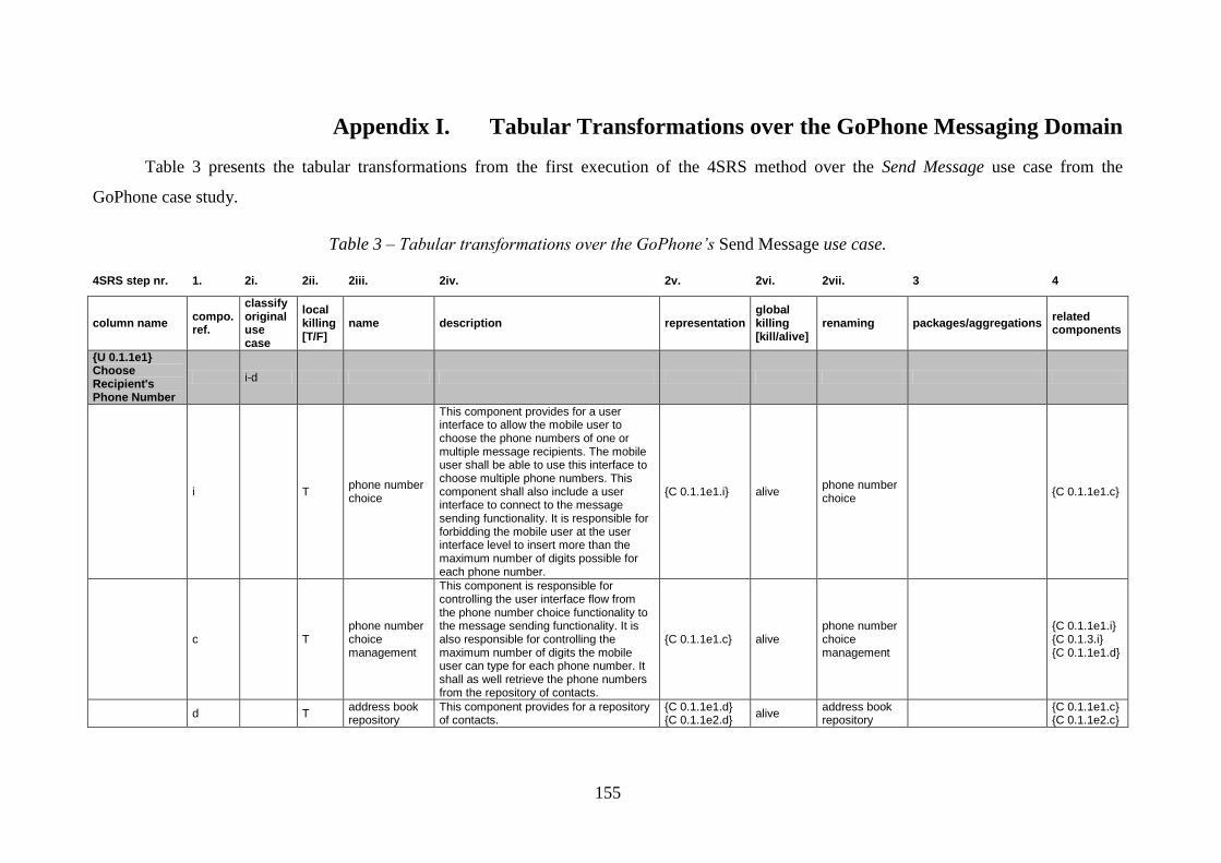
155
Appendix I. Tabular Transformations over the GoPhone Messaging Domain
Table 3 presents the tabular transformations from the first execution of the 4SRS method over the Send Message use case from the
GoPhone case study.
Table 3 – Tabular transformations over the GoPhone’s Send Message use case.
4SRS step nr. 1. 2i. 2ii. 2iii. 2iv. 2v. 2vi. 2vii. 3 4
column name compo. ref.
classify original use case
local killing [T/F]
name description representation global killing [kill/alive]
renaming packages/aggregations related components
{U 0.1.1e1} Choose Recipient's Phone Number
i-d
i T phone number choice
This component provides for a user interface to allow the mobile user to choose the phone numbers of one or multiple message recipients. The mobile user shall be able to use this interface to choose multiple phone numbers. This component shall also include a user interface to connect to the message sending functionality. It is responsible for forbidding the mobile user at the user interface level to insert more than the maximum number of digits possible for each phone number.
{C 0.1.1e1.i} alive phone number choice
{C 0.1.1e1.c}
c T phone number choice management
This component is responsible for controlling the user interface flow from the phone number choice functionality to the message sending functionality. It is also responsible for controlling the maximum number of digits the mobile user can type for each phone number. It shall as well retrieve the phone numbers from the repository of contacts.
{C 0.1.1e1.c} alive phone number choice management
{C 0.1.1e1.i} {C 0.1.3.i} {C 0.1.1e1.d}
d T address book repository
This component provides for a repository of contacts.
{C 0.1.1e1.d} {C 0.1.1e2.d}
alive address book repository
{C 0.1.1e1.c} {C 0.1.1e2.c}

156
{U 0.1.1e2} Choose Recipient's Phone Number or E-mail Address
i-d
i T phone number or e-mail address choice
This component provides for a user interface to allow the mobile user to choose the phone numbers or the e-mail addresses of one or multiple message recipients. The mobile user shall be able to use this interface to choose multiple phone numbers or multiple e-mail addresses. This component shall include a user interface to connect to the message sending functionality. It is responsible for forbidding the mobile user at the user interface level to insert more than the maximum number of digits possible for each phone number or to insert invalid e-mail addresses.
{C 0.1.1e2.i} alive phone number or e-mail address choice
{C 0.1.1e2.c}
c T
phone number or e-mail address choice management
This component is responsible for controlling the user interface flow from the phone number/e-mail address choice functionality to the message sending functionality. It is also responsible for controlling the maximum number of digits the mobile user can type for each phone number or the validity of e-mail addresses. It shall as well retrieve the phone numbers or the e-mail addresses from the repository of contacts.
{C 0.1.1e2.c} alive
phone number or e-mail address choice management
{C 0.1.1e2.i} {C 0.1.3.i} {C 0.1.1e1.d}
d T address book repository
This component provides for a repository of contacts.
{C 0.1.1e2.d} {C 0.1.1e1.d}
kill
{U 0.1.2.1e1} Select Basic or Extended Kind of Message
i
i T
basic or extended message kind selection
This component provides for a user interface to allow the mobile user to choose the kind of message to send (basic SMS or extended SMS). It shall include a user interface to connect to the message writing functionality.
{C 0.1.2.1e1.i} alive
basic or extended message kind selection
{C 0.1.2.1e1.c}
c T message kind selection management
This component is responsible for controlling the user interface flow from the basic/extended kind of message selection functionality to the message
{C 0.1.2.1e1.c} {C 0.1.2.1e2.c}
alive message kind selection management
{C 0.1.2.5.i}

157
writing functionality.
d F
{U 0.1.2.1e2} Select Basic, Extended or E-mail Kind of Message
i
i T
basic, extended or e-mail message kind selection
This component provides for a user interface to allow the mobile user to choose the kind of message to send (basic SMS, extended SMS or e-mail). It shall include a user interface to connect to the message writing functionality.
{C 0.1.2.1e2.i} alive
basic, extended or e-mail message kind selection
{C 0.1.2.1e1.c}
c T message kind selection management
This component is responsible for controlling the user interface flow from the basic/extended/e-mail kind of message selection functionality to the message writing functionality.
{C 0.1.2.1e2.c} {C 0.1.2.1e1.c}
kill
d F
{U 0.1.2.2e1} Activate Letter Combination
c-d
i T letter combination activation
This component provides for a user interface to allow the mobile user to activate the letter combination (into words from the word repository) according to the keys pressed by him when writing the message. It is responsible for notifying the mobile user on the activation/deactivation of the letter combination.
{C 0.1.2.2e1.i} alive letter combination activation
{C 0.1.2.2e1.c}
c T letter combination management
This component is actually responsible for activating/deactivating the letter combination, therefore it shall keep record of letter combination's activation state. It is also responsible for getting the possible combinations of letters (words) from the word repository according to the keys pressed by the mobile user when writing the message. It is responsible as well for composing and sending an alphabetically ordered list with those combinations (words) to the message writing functionality upon request. This component shall notify the message writing functionality on the changes to the letter combination's activation state,
{C 0.1.2.2e1.c} alive letter combination management
{C 0.1.2.2e1.i} {C 0.1.2.2e1.d} {C 0.1.2.5.c}

158
whenever that happens. It can also receive requests for updating the letter combination's activation state from the message writing functionality.
d T word repository
This component provides for a repository of possible combinations of letters (words) for the keys and language availables.
{C 0.1.2.2e1.d} alive word repository {C 0.1.2.2e1.c}
{U 0.1.2.3e1} Insert Picture
i-c-d
i T picture insertion
This component provides for a user interface to allow the mobile user to insert pictures into a message. The mobile user shall be able to use this interface to insert multiple pictures. This component is responsible for notifying the mobile user on the violation of validation rules over the pictures. This component receives requests for picture insertion from the message writing functionality.
{C 0.1.2.3e1.i} alive picture insertion
{C 0.1.2.3e1.c} {C 0.1.2.5.c}
c T picture insertion management
This component is actually responsible for inserting pictures into a message. It provides for the validation of the pictures to be inserted into the message. It is also responsible for retrieving pictures from the picture repository.
{C 0.1.2.3e1.c} alive picture insertion management
{C 0.1.2.3e1.i} {C 0.1.2.3e1.d}
d T picture repository
This component provides for a repository of pictures.
{C 0.1.2.3e1.d} {C 0.1.2.3e2.d} {C 0.1.2.4e1.d} {C 0.1.2.4e2.d}
alive object repository
{C 0.1.2.3e1.c} {C 0.1.2.3e2.c} {C 0.1.2.4e1.c} {C 0.1.2.4e2.c}
{U 0.1.2.3e2} Insert Picture or Draft Text
i-c-d
i T picture or draft text insertion
This component provides for a user interface to allow the mobile user to insert pictures and/or draft texts into a message. The mobile user shall be able to use this interface to insert multiple pictures and/or multiple draft texts. This component is responsible for notifying the
{C 0.1.2.3e2.i} alive picture or draft text insertion
{C 0.1.2.3e2.c} {C 0.1.2.5.c}
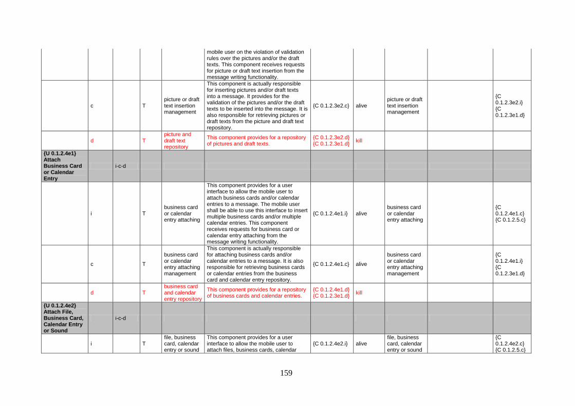
159
mobile user on the violation of validation rules over the pictures and/or the draft texts. This component receives requests for picture or draft text insertion from the message writing functionality.
c T picture or draft text insertion management
This component is actually responsible for inserting pictures and/or draft texts into a message. It provides for the validation of the pictures and/or the draft texts to be inserted into the message. It is also responsible for retrieving pictures or draft texts from the picture and draft text repository.
{C 0.1.2.3e2.c} alive picture or draft text insertion management
{C 0.1.2.3e2.i} {C 0.1.2.3e1.d}
d T picture and draft text repository
This component provides for a repository of pictures and draft texts.
{C 0.1.2.3e2.d} {C 0.1.2.3e1.d}
kill
{U 0.1.2.4e1} Attach Business Card or Calendar Entry
i-c-d
i T business card or calendar entry attaching
This component provides for a user interface to allow the mobile user to attach business cards and/or calendar entries to a message. The mobile user shall be able to use this interface to insert multiple business cards and/or multiple calendar entries. This component receives requests for business card or calendar entry attaching from the message writing functionality.
{C 0.1.2.4e1.i} alive business card or calendar entry attaching
{C 0.1.2.4e1.c} {C 0.1.2.5.c}
c T
business card or calendar entry attaching management
This component is actually responsible for attaching business cards and/or calendar entries to a message. It is also responsible for retrieving business cards or calendar entries from the business card and calendar entry repository.
{C 0.1.2.4e1.c} alive
business card or calendar entry attaching management
{C 0.1.2.4e1.i} {C 0.1.2.3e1.d}
d T business card and calendar entry repository
This component provides for a repository of business cards and calendar entries.
{C 0.1.2.4e1.d} {C 0.1.2.3e1.d}
kill
{U 0.1.2.4e2} Attach File, Business Card, Calendar Entry or Sound
i-c-d
i T file, business card, calendar entry or sound
This component provides for a user interface to allow the mobile user to attach files, business cards, calendar
{C 0.1.2.4e2.i} alive file, business card, calendar entry or sound
{C 0.1.2.4e2.c} {C 0.1.2.5.c}

160
attaching entries and/or sounds to a message. The mobile user shall be able to use this interface to insert multiple files, multiple business cards, multiple calendar entries and/or multiple sounds. This component is responsible for notifying the mobile user on the violation of validation rules over the files, the business cards, the calendar entries and/or the sounds. It receives requests for file, business card, calendar entry or sound attaching from the message writing functionality.
attaching
c T
file, business card, calendar entry or sound attaching management
This component is actually responsible for attaching files, business cards, calendar entries and/or sounds to a message. It is also responsible for the validation of the files and/or the sounds to be introduced to the message. It is responsible as well for retrieving files, business cards, calendar entries or sounds from the file, business card, calendar entry and sound repository.
{C 0.1.2.4e2.c} alive
file, business card, calendar entry or sound attaching management
{C 0.1.2.4e2.i} {C 0.1.2.3e1.d}
d T
file, business card, calendar entry and sound repository
This component provides for a repository of files, business cards, calendar entries and sounds.
{C 0.1.2.4e2.d} {C 0.1.2.3e1.d}
kill
{U 0.1.3} Send Message to Network
i
i T message sending
This component provides for an interface that receives messages for sending through the network. It is responsible for notifying the mobile user on the sending operation's initialization (message being sent) and on the success of the sending operation. It receives requests for message sending from the phone number choice functionality, or from the phone number or e-mail address choice functionality. It is also responsible for calling the message archiving functionality.
{C 0.1.3.i} alive message sending
{C 0.1.3.c} {C 0.1.4e1.i} {C 0.1.4e2.i}
c T message sending management
This component is responsible for actually sending the message through the network and controling the state of the message sending (message successfully sent or message not sent).
{C 0.1.3.c} alive message sending management
{C 0.1.3.i}

161
d F
{U 0.1.4e1} Archive Message by Request
d
i T message archiving by request
This component provides for a user interface to ask the mobile user whether he wants to save the message into the sent messages folder or not. It is reponsible for notifying the mobile user on the success of the archiving operation. It receives requests for message archiving from the message sending functionality.
{C 0.1.4e1.i} alive message archiving by request
{C 0.1.4e1.c}
c T message archiving management
This component is responsible for verifying the memory space for archiving messages into the sent messages folder. It is also responsible for controlling the state of the message archiving (message archived or message not archived). It is responsible as well for saving the sent messages into the message repository.
{C 0.1.4e1.c} {C 0.1.4e2.c}
alive message archiving management
{C 0.1.4e1.i} {C 0.1.4e2.i} {C 0.1.4e1.d}
d T message repository
This component provides for a repository of messages (sent messages folder).
{C 0.1.4e1.d} {C 0.1.4e2.d}
alive message repository
{C 0.1.4e1.c}
{U 0.1.4e2} Automatically Archive Message
d
i T automatic message archiving
This component is responsible for notifying the mobile user on the success of the archiving operation. It receives requests for message archiving from the message sending functionality.
{C 0.1.4e2.i} alive automatic message archiving
{C 0.1.4e1.c}
c T message archiving management
This component is responsible for verifying the memory space for archiving messages into the sent messages folder. It is also responsible for controlling the state of the message archiving (message archived or message not archived). It receives requests for message archiving from the message sending functionality.
{C 0.1.4e2.c} {C 0.1.4e1.c}
kill
d T message repository
This component provides for a repository of messages (sent messages folder).
{C 0.1.4e2.d} {C 0.1.4e1.d}
kill
{U 0.1.2.5} Write Message
d

162
i T message writing
This component provides for a user interface to allow the mobile user to write a message in the message area of the message editor (which is a text editor). If the letter combination is supported and activated, the user interface shall display the first possible combination of letters (words) for the keys pressed by the mobile user and allow him to choose other combinations from the word repository. This component is responsible for displaying to the mobile user the alerts of maximum number of characters reached. It shall include a user interface to connect to the object insertion functionality (either pictures, or pictures or draft texts), to the object attaching functionality (either business cards or calendar entries, or files, business cards, calendar entries or sounds), to the recipient's contact choice functionality (either phone numbers, or phone numbers or e-mail addresses) and to the letter combination activation functionality. This component receives requests for message writing from the basic or extended kind of message selection functionality, or from the basic, extended or e-mail kind of message selection functionality.
{C 0.1.2.5.i} alive message writing
{C 0.1.2.5.c}

163
c T message text management
This component is responsible for keeping a local record of the letter combination's activation state, which is updated upon initialization (by requesting it to the letter combination management) and whenever it changes (by notification from the letter combination management). It is also responsible for getting the list of possible combinations of letters (words) from the letter combination management for the keys pressed by the mobile user. It is responsible as well for controlling the number of characters in the message's text according to the kind of message. It shall generate alerts of maximum number of characters reached to be displayed to the mobile user. This component is responsible as well for controlling the user interface flow from the message writing functionality to the object insertion functionality (either pictures, or pictures or draft texts), to the object attaching functionality (either business cards or calendar entries, or files, business cards, calendar entries or sounds), to the recipient's contact choice functionality and to the letter combination activation functionality.
{C 0.1.2.5.c} alive message text management
{C 0.1.2.5.i} {C 0.1.2.2e1.c} {C 0.1.2.3e1.i} {C 0.1.2.3e2.i} {C 0.1.2.4e1.i} {C 0.1.2.4e2.i} {C 0.1.1e1.i} {C 0.1.1e2.i} {C 0.1.2.2e1.i}
d F
Table 4 shows the tabular transformations from the first recursive execution of the 4SRS method over the object insertion and object
attaching functionalities from the GoPhone’s messaging domain.
Table 4 – Tabular transformations over the GoPhone’s object insertion and object attaching functionalities.
4SRS step nr. 1. 2i. 2ii. 2iii. 2iv. 2v. 2vi. 2vii. 3 4
column name compo. ref.
classify original use case
local killing [T/F]
name description representation global killing [kill/alive]
renaming packages/aggregations related components
{U 1.1.2.3e1.1} Browse
i-c-d

164
Directory of Pictures
i T picture directory browsing
This component provides for a user interface to show the picture files in a directory of picture files (eventually with folders). The directory can be browsed for selection of those picture files. The mobile user shall be able to use this interface to select multiple picture files. This component is responsible for showing the picture files in the directory with a small image of the picture (icon) next to them.
{C 1.1.2.3e1.1.i} {C 1.1.2.3e2.1.i}
alive picture directory browsing
{C 1.1.2.3e1.1.c} {C 1.1.2.3e1.2.i}
c T
picture directory browsing management
This component is responsible for retrieving the picture files from the picture file repository and resizing them to the icon size.
{C 1.1.2.3e1.1.c} {C 1.1.2.3e2.1.c}
alive
picture directory browsing management
{C 1.1.2.3e1.1.i} {C 1.1.2.3e1.1.d}
d T picture file repository
This component provides for a repository of files.
{C 1.1.2.3e1.1.d} {C 1.1.2.3e1.2.d} {C 1.1.2.3e2.1.d} {C 1.1.2.3e2.2.d} {C 1.1.2.3e2.3.d} {C 1.1.2.3e2.4.d} {C 1.1.2.4e2.1.d} {C 1.1.2.4e2.4.d} {C 1.1.2.4e2.7.d}
alive general file repository
{C 1.1.2.3e1.1.c} {C 1.1.2.3e1.2.c} {C 1.1.2.3e2.4.c} {C 1.1.2.4e2.1.c} {C 1.1.2.4e2.8.c} {C 1.1.2.4e2.4.c} {C 1.1.2.4e2.7.c}
{U 1.1.2.3e1.2} Display Picture in Message Area
i-c-d
i T picture displaying
This component is responsible for displaying pictures in the message area of the message editor. It is also responsible for notifying the mobile user on the violation of size constraints over the picture files.
{C 1.1.2.3e1.2.i} {C 1.1.2.3e2.3.i}
alive picture displaying
{C 1.1.2.3e1.2.c}
c T picture displaying management
This component provides for the validation of size constraints over the picture files. It is also responsible for retrieving them from the picture file repository and resizing them to fit the message area.
{C 1.1.2.3e1.2.c} {C 1.1.2.3e2.3.c}
alive picture displaying management
{C 1.1.2.3e1.2.i} {C 1.1.2.3e1.1.d}
d T picture file repository
This component provides for a repository of files.
{C 1.1.2.3e1.2.d} {C 1.1.2.3e1.1.d}
kill
{U 1.1.2.3e2.1} Browse Directory of
i-c-d

165
Pictures
i T picture directory browsing
This component provides for a user interface to show the picture files in a directory of picture files (eventually with folders). The directory can be browsed for selection of those picture files. The mobile user shall be able to use this interface to select multiple picture files. This component is responsible for showing the picture files in the directory with a small image of the picture (icon) next to them.
{C 1.1.2.3e2.1.i} {C 1.1.2.3e1.1.i}
kill
c T
picture directory browsing management
This component is responsible for retrieving the picture files from the picture file repository and resizing them to the icon size.
{C 1.1.2.3e2.1.c} {C 1.1.2.3e1.1.c}
kill
d T picture file repository
This component provides for a repository of files.
{C 1.1.2.3e2.1.d} {C 1.1.2.3e1.1.d}
kill
{U 1.1.2.3e2.2} Browse List of Draft Texts
i-c-d
i T draft text list browsing
This component provides for a user interface to show the draft text files in a list. It can be browsed for selection of those draft text files. The mobile user shall be able to use this interface to select multiple draft text files. This component is responsible for presenting the draft text files in the list by showing the beginning of the text (fitting the user interface's length).
{C 1.1.2.3e2.2.i} alive draft text list browsing
{C 1.1.2.3e2.4.c} {C 1.1.2.3e2.4.i}
c T draft text list browsing management
This component is responsible for retrieving the draft text files from the draft text file repository.
{C 1.1.2.3e2.2.c} {C 1.1.2.3e2.4.c}
kill
d T draft text file repository
This component provides for a repository of files.
{C 1.1.2.3e2.2.d} {C 1.1.2.3e1.1.d}
kill
{U 1.1.2.3e2.3} Display Picture in Message Area
i-c-d
i T picture displaying
This component is responsible for displaying pictures in the message area of the message editor. It is also responsible for notifying the mobile user on the violation of size constraints over the picture files.
{C 1.1.2.3e2.3.i} {C 1.1.2.3e1.2.i}
kill

166
c T picture displaying management
This component provides for the validation of size constraints over the picture files. It is also responsible for retrieving them from the picture file repository and resizing them to fit the message area.
{C 1.1.2.3e2.3.c} {C 1.1.2.3e1.2.c}
kill
d T picture file repository
This component provides for a repository of files.
{C 1.1.2.3e2.3.d} {C 1.1.2.3e1.1.d}
kill
{U 1.1.2.3e2.4} Display Draft Text in Message Area
i-c-d
i T draft text displaying
This component is responsible for displaying draft texts in the message area of the message editor. It is also responsible for notifying the mobile user on the violation of length constraints over the text files.
{C 1.1.2.3e2.4.i} alive draft text displaying
{C 1.1.2.3e2.4.c}
c T draft text displaying management
This component provides for the validation of length constraints (character number) over the text files. It is also responsible for retrieving them from the draft text file repository.
{C 1.1.2.3e2.4.c} {C 1.1.2.3e2.2.c}
alive draft text management
{C 1.1.2.3e2.4.i} {C 1.1.2.3e1.1.d} {C 1.1.2.3e2.2.i}
d T draft text file repository
This component provides for a repository of files.
{C 1.1.2.3e2.4.d} {C 1.1.2.3e1.1.d}
kill
{U 1.1.2.4e1.1} Browse List of Business Cards
i-c-d
i T business card list browsing
This component provides for a user interface to show the business cards in a list. It can be browsed for selection of those business cards. The mobile user shall be able to use this interface to select multiple business cards.
{C 1.1.2.4e1.1.i} {C 1.1.2.4e2.2.i}
alive business card list browsing
{C 1.1.2.4e1.1.c} {C 1.1.2.4e1.3.i}
c T business card list browsing management
This component is responsible for retrieving business cards from the business card repository (by business card holder).
{C 1.1.2.4e1.1.c} {C 1.1.2.4e1.3.c} {C 1.1.2.4e2.2.c} {C 1.1.2.4e2.5.c}
alive business card management
{C 1.1.2.4e1.1.i} {C 1.1.2.4e1.1.d} {C 1.1.2.4e1.3.i}
d T business card repository
This component provides for a repository of business cards.
{C 1.1.2.4e1.1.d} {C 1.1.2.4e1.3.d} {C 1.1.2.4e2.2.d} {C 1.1.2.4e2.5.d}
alive business card repository
{C 1.1.2.4e1.1.c}
{U 1.1.2.4e1.2} Browse Calendar
i-c-d

167
i T calendar browsing
This component provides for a user interface to show the calendar entries in a calendar. It can be browsed for selection of those calendar entries. The mobile user shall be able to use this interface to select multiple calendar entries. This component is responsible for showing the text of the calendar entries concerning each day while the mobile user browses the calendar.
{C 1.1.2.4e1.2.i} {C 1.1.2.4e2.3.i}
alive calendar browsing
{C 1.1.2.4e1.2.c} {C 1.1.2.4e1.3.i}
c T calendar browsing management
This component is responsible for retrieving calendar entries from the calendar (by date).
{C 1.1.2.4e1.2.c} {C 1.1.2.4e1.4.c} {C 1.1.2.4e2.3.c} {C 1.1.2.4e2.6.c}
alive calendar management
{C 1.1.2.4e1.2.i} {C 1.1.2.4e1.2.d} {C 1.1.2.4e1.3.i}
d T calendar This component provides for a repository of calendar entries.
{C 1.1.2.4e1.2.d} {C 1.1.2.4e1.4.d} {C 1.1.2.4e2.3.d} {C 1.1.2.4e2.6.d}
alive calendar {C 1.1.2.4e1.2.c}
{U 1.1.2.4e1.3} Add Business Card to Attachments List
i-c-d
i T business card addition
This component is responsible for adding items to the attachments list in the message editor.
{C 1.1.2.4e1.3.i} {C 1.1.2.4e1.4.i}
alive business card or calendar entry addition
{C 1.1.2.4e1.1.c} {C 1.1.2.4e1.2.c}
c T business card addition management
This component is responsible for retrieving business cards from the business card repository (by business card holder).
{C 1.1.2.4e1.3.c} {C 1.1.2.4e1.1.c}
kill
d T business card repository
This component provides for a repository of business cards.
{C 1.1.2.4e1.3.d} {C 1.1.2.4e1.1.d}
kill
{U 1.1.2.4e1.4} Add Calendar Entry to Attachments List
i-c-d
i T calendar entry addition
This component is responsible for adding items to the attachments list in the message editor.
{C 1.1.2.4e1.4.i} {C 1.1.2.4e1.3.i}
kill
c T calendar entry addition management
This component is responsible for retrieving calendar entries from the calendar (by date).
{C 1.1.2.4e1.4.c} {C 1.1.2.4e1.2.c}
kill
d T calendar This component provides for a repository of calendar entries.
{C 1.1.2.4e1.4.d} {C 1.1.2.4e1.2.d}
kill
{U 1.1.2.4e2.1} Browse
i-c-d
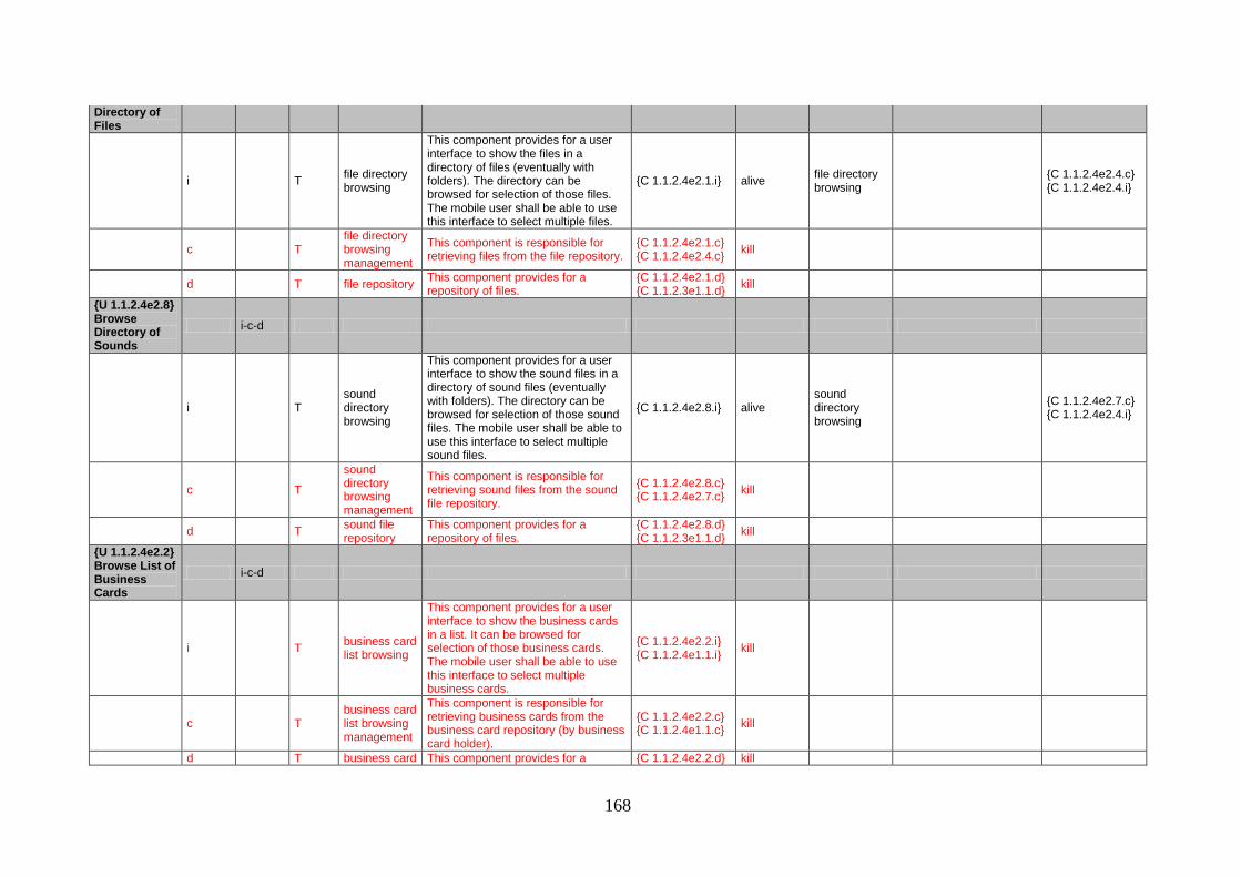
168
Directory of Files
i T file directory browsing
This component provides for a user interface to show the files in a directory of files (eventually with folders). The directory can be browsed for selection of those files. The mobile user shall be able to use this interface to select multiple files.
{C 1.1.2.4e2.1.i} alive file directory browsing
{C 1.1.2.4e2.4.c} {C 1.1.2.4e2.4.i}
c T file directory browsing management
This component is responsible for retrieving files from the file repository.
{C 1.1.2.4e2.1.c} {C 1.1.2.4e2.4.c}
kill
d T file repository This component provides for a repository of files.
{C 1.1.2.4e2.1.d} {C 1.1.2.3e1.1.d}
kill
{U 1.1.2.4e2.8} Browse Directory of Sounds
i-c-d
i T sound directory browsing
This component provides for a user interface to show the sound files in a directory of sound files (eventually with folders). The directory can be browsed for selection of those sound files. The mobile user shall be able to use this interface to select multiple sound files.
{C 1.1.2.4e2.8.i} alive sound directory browsing
{C 1.1.2.4e2.7.c} {C 1.1.2.4e2.4.i}
c T
sound directory browsing management
This component is responsible for retrieving sound files from the sound file repository.
{C 1.1.2.4e2.8.c} {C 1.1.2.4e2.7.c}
kill
d T sound file repository
This component provides for a repository of files.
{C 1.1.2.4e2.8.d} {C 1.1.2.3e1.1.d}
kill
{U 1.1.2.4e2.2} Browse List of Business Cards
i-c-d
i T business card list browsing
This component provides for a user interface to show the business cards in a list. It can be browsed for selection of those business cards. The mobile user shall be able to use this interface to select multiple business cards.
{C 1.1.2.4e2.2.i} {C 1.1.2.4e1.1.i}
kill
c T business card list browsing management
This component is responsible for retrieving business cards from the business card repository (by business card holder).
{C 1.1.2.4e2.2.c} {C 1.1.2.4e1.1.c}
kill
d T business card This component provides for a {C 1.1.2.4e2.2.d} kill

169
repository repository of business cards. {C 1.1.2.4e1.1.d}
{U 1.1.2.4e2.3} Browse Calendar
i-c-d
i T calendar browsing
This component provides for a user interface to show the calendar entries in a calendar. It can be browsed for selection of those calendar entries. The mobile user shall be able to use this interface to select multiple calendar entries. This component is responsible for showing the text of the calendar entries concerning each day while the mobile user browses the calendar.
{C 1.1.2.4e2.3.i} {C 1.1.2.4e1.2.i}
kill
c T calendar browsing management
This component is responsible for retrieving calendar entries from the calendar (by date).
{C 1.1.2.4e2.3.c} {C 1.1.2.4e1.2.c}
kill
d T calendar This component provides for a repository of calendar entries.
{C 1.1.2.4e2.3.d} {C 1.1.2.4e1.2.d}
kill
{U 1.1.2.4e2.4} Add File to Attachments List
i-c-d
i T file addition
This component is responsible for adding files to the attachments list in the message editor. It is also responsible for notifying the mobile user on the violation of size constraints over the files.
{C 1.1.2.4e2.4.i} {C 1.1.2.4e2.7.i}
alive file or sound file addition
{C 1.1.2.4e2.4.c}
c T file addition management
This component provides for the validation of size constraints over the files. It is responsible for retrieving them from the file repository.
{C 1.1.2.4e2.4.c} {C 1.1.2.4e2.1.c}
alive file management
{C 1.1.2.4e2.4.i} {C 1.1.2.3e1.1.d} {C 1.1.2.4e2.1.i}
d T file repository This component provides for a repository of files.
{C 1.1.2.4e2.4.d} {C 1.1.2.3e1.1.d}
kill
{U 1.1.2.4e2.5} Add Business Card to Attachments List
i-c-d
i T business card addition
This component is responsible for adding items to the attachments list in the message editor.
{C 1.1.2.4e2.5.i} {C 1.1.2.4e1.3.i}
kill
c T business card addition management
This component is responsible for retrieving business cards from the business card repository (by business card holder).
{C 1.1.2.4e2.5.c} {C 1.1.2.4e1.1.c}
kill

170
d T business card repository
This component provides for a repository of business cards.
{C 1.1.2.4e2.5.d} {C 1.1.2.4e1.1.d}
kill
{U 1.1.2.4e2.6} Add Calendar Entry to Attachments List
i-c-d
i T calendar entry addition
This component is responsible for adding items to the attachments list in the message editor.
{C 1.1.2.4e2.6.i} {C 1.1.2.4e1.3.i}
kill
c T calendar entry addition management
This component is responsible for retrieving calendar entries from the calendar (by date).
{C 1.1.2.4e2.6.c} {C 1.1.2.4e1.2.c}
kill
d T calendar This component provides for a repository of calendar entries.
{C 1.1.2.4e2.6.d} {C 1.1.2.4e1.2.d}
kill
{U 1.1.2.4e2.7} Add Sound to Attachments List
i-c-d
i T sound file addition
This component is responsible for adding sound files to the attachments list in the message editor. It is also responsible for notifying the mobile user on the violation of size constraints over the sound files.
{C 1.1.2.4e2.7.i} {C 1.1.2.4e2.4.i}
kill
c T sound file addition management
This component provides for the validation of size constraints over the sound files. It is responsible for retrieving them from the sound file repository.
{C 1.1.2.4e2.7.c} {C 1.1.2.4e2.8.c}
alive sound file management
{C 1.1.2.4e2.8.i} {C 1.1.2.3e1.1.d}
d T sound file repository
This component provides for a repository of files.
{C 1.1.2.4e2.7.d} {C 1.1.2.3e1.1.d}
kill