escaner kodak I200 SERVICE MANUAL.pdf
70
i200 Series Scanners User’s Guide A-61167 Part No. 9E3968 CAT No. 850 7543 KODAK iNnovation Series Scanners
-
Upload
fernando-palma-galindo -
Category
Documents
-
view
29 -
download
3
Transcript of escaner kodak I200 SERVICE MANUAL.pdf

i200 Series Scanners
User’sGuide
A-61167
Part No. 9E3968
CAT No. 850 7543
KODAK iNnovation Series Scanners

A-61167 April 2005 i
Contents
Introduction . . . . . . . . . . . . . . . . . . . . . . . . . . . . . . . . . . . . . . . . . . . . . . . . . . . . 1Scanner features . . . . . . . . . . . . . . . . . . . . . . . . . . . . . . . . . . . . . . . . . . . . . . 1Paper transport features . . . . . . . . . . . . . . . . . . . . . . . . . . . . . . . . . . . . . . . . . 2
Speed/capacity (throughput) . . . . . . . . . . . . . . . . . . . . . . . . . . . . . . . . . . . 2Image quality features . . . . . . . . . . . . . . . . . . . . . . . . . . . . . . . . . . . . . . . . . . 2Maintenance . . . . . . . . . . . . . . . . . . . . . . . . . . . . . . . . . . . . . . . . . . . . . . . . . . 2Optional accessories . . . . . . . . . . . . . . . . . . . . . . . . . . . . . . . . . . . . . . . . . . . 3Preparing documents for scanning . . . . . . . . . . . . . . . . . . . . . . . . . . . . . . . . . 3
Recommended documents . . . . . . . . . . . . . . . . . . . . . . . . . . . . . . . . . . . . 4Safety information . . . . . . . . . . . . . . . . . . . . . . . . . . . . . . . . . . . . . . . . . . . . . 5
Warning labels . . . . . . . . . . . . . . . . . . . . . . . . . . . . . . . . . . . . . . . . . . . . . . 5User precautions . . . . . . . . . . . . . . . . . . . . . . . . . . . . . . . . . . . . . . . . . . . . . . 5Safety and regulatory agency approvals . . . . . . . . . . . . . . . . . . . . . . . . . . . . 6Environmental information . . . . . . . . . . . . . . . . . . . . . . . . . . . . . . . . . . . . . . . 7Acoustic emission . . . . . . . . . . . . . . . . . . . . . . . . . . . . . . . . . . . . . . . . . . . . . . 7Power system . . . . . . . . . . . . . . . . . . . . . . . . . . . . . . . . . . . . . . . . . . . . . . . . . 7EMC statements . . . . . . . . . . . . . . . . . . . . . . . . . . . . . . . . . . . . . . . . . . . . . . . 8
United States . . . . . . . . . . . . . . . . . . . . . . . . . . . . . . . . . . . . . . . . . . . . . . . 8Japan . . . . . . . . . . . . . . . . . . . . . . . . . . . . . . . . . . . . . . . . . . . . . . . . . . . . . 8Taiwan . . . . . . . . . . . . . . . . . . . . . . . . . . . . . . . . . . . . . . . . . . . . . . . . . . . . 8People’s Republic of China . . . . . . . . . . . . . . . . . . . . . . . . . . . . . . . . . . . . 8European Union (EU) . . . . . . . . . . . . . . . . . . . . . . . . . . . . . . . . . . . . . . . . . 8
Installing the Scanner . . . . . . . . . . . . . . . . . . . . . . . . . . . . . . . . . . . . . . . . . . . . 9Site specifications . . . . . . . . . . . . . . . . . . . . . . . . . . . . . . . . . . . . . . . . . . . . . . 9System requirements . . . . . . . . . . . . . . . . . . . . . . . . . . . . . . . . . . . . . . . . . . 10
Minimum system configuration . . . . . . . . . . . . . . . . . . . . . . . . . . . . . . . . 10Recommended system configuration . . . . . . . . . . . . . . . . . . . . . . . . . . . . 10
Unpacking the scanner . . . . . . . . . . . . . . . . . . . . . . . . . . . . . . . . . . . . . . . . . 11Registering your scanner . . . . . . . . . . . . . . . . . . . . . . . . . . . . . . . . . . . . . . . 11Scanner components . . . . . . . . . . . . . . . . . . . . . . . . . . . . . . . . . . . . . . . . . . 11
Front . . . . . . . . . . . . . . . . . . . . . . . . . . . . . . . . . . . . . . . . . . . . . . . . . . . . . 11Rear . . . . . . . . . . . . . . . . . . . . . . . . . . . . . . . . . . . . . . . . . . . . . . . . . . . . . 12Side . . . . . . . . . . . . . . . . . . . . . . . . . . . . . . . . . . . . . . . . . . . . . . . . . . . . . 12Internal . . . . . . . . . . . . . . . . . . . . . . . . . . . . . . . . . . . . . . . . . . . . . . . . . . . 12
Making connections . . . . . . . . . . . . . . . . . . . . . . . . . . . . . . . . . . . . . . . . . . . 13Installing the IEEE-1394 (FireWire) card in the host computer . . . . . . . . 13Installing the Kodak Driver Software . . . . . . . . . . . . . . . . . . . . . . . . . . . . 13Installing the IEEE-1394 (FireWire) cable . . . . . . . . . . . . . . . . . . . . . . . . 13Power setup . . . . . . . . . . . . . . . . . . . . . . . . . . . . . . . . . . . . . . . . . . . . . . . 14

ii A-61167 April 2005
Input and output trays . . . . . . . . . . . . . . . . . . . . . . . . . . . . . . . . . . . . . . . . . . 17Attaching the input tray . . . . . . . . . . . . . . . . . . . . . . . . . . . . . . . . . . . . . . 17Attaching the output tray . . . . . . . . . . . . . . . . . . . . . . . . . . . . . . . . . . . . . 17Tray extenders and side guides . . . . . . . . . . . . . . . . . . . . . . . . . . . . . . . . 17Adjusting the output tray . . . . . . . . . . . . . . . . . . . . . . . . . . . . . . . . . . . . . 18Closing the input and output trays . . . . . . . . . . . . . . . . . . . . . . . . . . . . . . 18Installing optional accessories . . . . . . . . . . . . . . . . . . . . . . . . . . . . . . . . . 18
Using the Scanner . . . . . . . . . . . . . . . . . . . . . . . . . . . . . . . . . . . . . . . . . . . . . . 19Starting and stopping scanning . . . . . . . . . . . . . . . . . . . . . . . . . . . . . . . . . . 19Automatic feeding . . . . . . . . . . . . . . . . . . . . . . . . . . . . . . . . . . . . . . . . . . . . . 19
Continuous feeding . . . . . . . . . . . . . . . . . . . . . . . . . . . . . . . . . . . . . . . . . 19Manual feeding . . . . . . . . . . . . . . . . . . . . . . . . . . . . . . . . . . . . . . . . . . . . . . . 20
Damaged documents . . . . . . . . . . . . . . . . . . . . . . . . . . . . . . . . . . . . . . . . 20Additional features . . . . . . . . . . . . . . . . . . . . . . . . . . . . . . . . . . . . . . . . . . . . 21
Long Paper mode . . . . . . . . . . . . . . . . . . . . . . . . . . . . . . . . . . . . . . . . . . 21Special Document mode . . . . . . . . . . . . . . . . . . . . . . . . . . . . . . . . . . . . . 21Perfect Page with iThresholding . . . . . . . . . . . . . . . . . . . . . . . . . . . . . . . . 21Toggle Patch . . . . . . . . . . . . . . . . . . . . . . . . . . . . . . . . . . . . . . . . . . . . . . 22
Maintenance . . . . . . . . . . . . . . . . . . . . . . . . . . . . . . . . . . . . . . . . . . . . . . . . . . 23Cleaning the scanner . . . . . . . . . . . . . . . . . . . . . . . . . . . . . . . . . . . . . . . . . . 23
Cleaning the separator module . . . . . . . . . . . . . . . . . . . . . . . . . . . . . . . . 24Cleaning the feed module . . . . . . . . . . . . . . . . . . . . . . . . . . . . . . . . . . . . 25Cleaning the drive rollers and transport area . . . . . . . . . . . . . . . . . . . . . . 26Cleaning the imaging guides . . . . . . . . . . . . . . . . . . . . . . . . . . . . . . . . . . 27Cleaning the paper path . . . . . . . . . . . . . . . . . . . . . . . . . . . . . . . . . . . . . . 28
Replacing parts . . . . . . . . . . . . . . . . . . . . . . . . . . . . . . . . . . . . . . . . . . . . . . 28Calibrating the scanner . . . . . . . . . . . . . . . . . . . . . . . . . . . . . . . . . . . . . . . . 29
Troubleshooting . . . . . . . . . . . . . . . . . . . . . . . . . . . . . . . . . . . . . . . . . . . . . . . 30Indicator lights . . . . . . . . . . . . . . . . . . . . . . . . . . . . . . . . . . . . . . . . . . . . . . . 30Lamps . . . . . . . . . . . . . . . . . . . . . . . . . . . . . . . . . . . . . . . . . . . . . . . . . . . . . . 30Clearing document jams . . . . . . . . . . . . . . . . . . . . . . . . . . . . . . . . . . . . . . . . 30Adjusting the separator module tension . . . . . . . . . . . . . . . . . . . . . . . . . . . . 31System is not responding . . . . . . . . . . . . . . . . . . . . . . . . . . . . . . . . . . . . . . . 32Color image quality . . . . . . . . . . . . . . . . . . . . . . . . . . . . . . . . . . . . . . . . . . . . 32Problem solving . . . . . . . . . . . . . . . . . . . . . . . . . . . . . . . . . . . . . . . . . . . . . . 33Transporting the scanner . . . . . . . . . . . . . . . . . . . . . . . . . . . . . . . . . . . . . . . 35

A-61167 April 2005 iii
Appendix A Specifications . . . . . . . . . . . . . . . . . . . . . . . . . . . . . . . . . . . . . A-1
Appendix B Supplies and Accessories . . . . . . . . . . . . . . . . . . . . . . . . . . . B-1
Appendix C Kodak i200 Series Imprinter . . . . . . . . . . . . . . . . . . . . . . . . . C-1Contents of the imprinter kit . . . . . . . . . . . . . . . . . . . . . . . . . . . . . . . . . . . . C-1Installing the imprinter . . . . . . . . . . . . . . . . . . . . . . . . . . . . . . . . . . . . . . . . C-2
Removing the circuit board cover . . . . . . . . . . . . . . . . . . . . . . . . . . . . . C-2Attaching the imprinter board and cable . . . . . . . . . . . . . . . . . . . . . . . . C-3Completing the imprinter installation . . . . . . . . . . . . . . . . . . . . . . . . . . . C-8
Installing the ink blotter strips . . . . . . . . . . . . . . . . . . . . . . . . . . . . . . . . . . C-10Installing an ink cartridge . . . . . . . . . . . . . . . . . . . . . . . . . . . . . . . . . . . . . C-12Setting the imprinter position . . . . . . . . . . . . . . . . . . . . . . . . . . . . . . . . . . C-12Imprinter maintenance . . . . . . . . . . . . . . . . . . . . . . . . . . . . . . . . . . . . . . . C-13
Imprinting problems . . . . . . . . . . . . . . . . . . . . . . . . . . . . . . . . . . . . . . . C-13Expected life of imprinter components . . . . . . . . . . . . . . . . . . . . . . . . . C-13When the imprinter is not in use . . . . . . . . . . . . . . . . . . . . . . . . . . . . . C-13Replacing an ink cartridge . . . . . . . . . . . . . . . . . . . . . . . . . . . . . . . . . . C-13Replacing the ink blotter strips . . . . . . . . . . . . . . . . . . . . . . . . . . . . . . . C-14Replacing the ink cartridge carrier . . . . . . . . . . . . . . . . . . . . . . . . . . . . C-15
Imprinting overview . . . . . . . . . . . . . . . . . . . . . . . . . . . . . . . . . . . . . . . . . C-16Print characters . . . . . . . . . . . . . . . . . . . . . . . . . . . . . . . . . . . . . . . . . . C-16
Imprinter specifications . . . . . . . . . . . . . . . . . . . . . . . . . . . . . . . . . . . . . . . C-17
Appendix D Kodak i200 Series Dockable Flatbed . . . . . . . . . . . . . . . . . . D-1Contents of the dockable flatbed kit . . . . . . . . . . . . . . . . . . . . . . . . . . . . . . D-1Flatbed specifications . . . . . . . . . . . . . . . . . . . . . . . . . . . . . . . . . . . . . . . . . D-1Installing the dockable flatbed . . . . . . . . . . . . . . . . . . . . . . . . . . . . . . . . . . D-1Using the flatbed . . . . . . . . . . . . . . . . . . . . . . . . . . . . . . . . . . . . . . . . . . . . D-3
Book scanning . . . . . . . . . . . . . . . . . . . . . . . . . . . . . . . . . . . . . . . . . . . . D-3Calibrating the flatbed . . . . . . . . . . . . . . . . . . . . . . . . . . . . . . . . . . . . . . . . D-4Cleaning the flatbed . . . . . . . . . . . . . . . . . . . . . . . . . . . . . . . . . . . . . . . . . . D-5After a power failure . . . . . . . . . . . . . . . . . . . . . . . . . . . . . . . . . . . . . . . . . . D-5Removing the dockable flatbed . . . . . . . . . . . . . . . . . . . . . . . . . . . . . . . . . D-6
Appendix E Installing Optional Memory . . . . . . . . . . . . . . . . . . . . . . . . . . E-1Installing memory in the scanner . . . . . . . . . . . . . . . . . . . . . . . . . . . . . . . . E-1
A-61167 April 2005 1
Introduction
Before you install and operate your Kodak i200 Series Scanner, take a few minutes to read through this guide. It contains important information about installing, using, and maintaining your scanner.
• Kodak i250 Scanner is a desktop simplex color scanner with an automatic document feeder.
• Kodak i260 Scanner is a desktop duplex color scanner with an automatic document feeder.
• Kodak i280 Scanner is a desktop duplex color scanner with an automatic document feeder.
Scanner features • Excellent paper handling, image quality, and reliability
• Color at the same speed as bi-tonal and grayscale
• Simultaneous color and bi-tonal output
• Long Paper and Special Document scanning modes (i280 Scanner only)
• Perfect Page with iThresholding for better image and text legibility, smoother lines, minimal to no artifacts, and fewer shaded areas
• Toggle patch to enable color on-the-fly processing (i280 Scanner only)
• Aggressive cropping capability to eliminate residual black border on any image edges
• Easy to use and maintain
• Handles a broad range of paper weights and sizes
• Small footprint; fits easily on a desktop or table
• Low noise level
• Easy installation
• ISIS and TWAIN device drivers are included on a CD that is packed with each scanner
• International language support
• Automatic overlap/multifeed detection
• All scanner models support multiple electrical power requirements for use worldwide
• May be user-calibrated at any time
• Electronic red, green, and blue color dropout
2 A-61167 April 2005
Paper transport features
• Automatic and manual feeding
• Multifeed detection by document length and/or document thickness
• Automatic document feeder (ADF) with operator-assisted “infinite” and single-sheet feeding
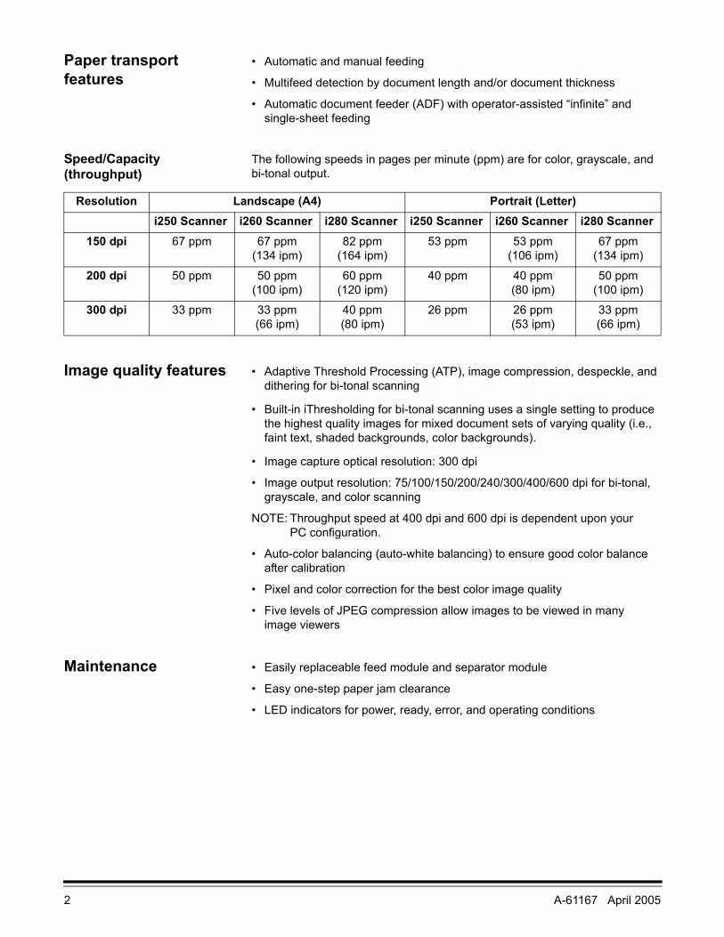
Speed/Capacity (throughput)
The following speeds in pages per minute (ppm) are for color, grayscale, and bi-tonal output.
Image quality features • Adaptive Threshold Processing (ATP), image compression, despeckle, and dithering for bi-tonal scanning
• Built-in iThresholding for bi-tonal scanning uses a single setting to produce the highest quality images for mixed document sets of varying quality (i.e., faint text, shaded backgrounds, color backgrounds).
• Image capture optical resolution: 300 dpi
• Image output resolution: 75/100/150/200/240/300/400/600 dpi for bi-tonal, grayscale, and color scanning
NOTE: Throughput speed at 400 dpi and 600 dpi is dependent upon your PC configuration.
• Auto-color balancing (auto-white balancing) to ensure good color balance after calibration
• Pixel and color correction for the best color image quality
• Five levels of JPEG compression allow images to be viewed in many image viewers
Maintenance • Easily replaceable feed module and separator module
• Easy one-step paper jam clearance
• LED indicators for power, ready, error, and operating conditions
Resolution Landscape (A4) Portrait (Letter)i250 Scanner i260 Scanner i280 Scanner i250 Scanner i260 Scanner i280 Scanner
150 dpi 67 ppm 67 ppm (134 ipm)
82 ppm (164 ipm)
53 ppm 53 ppm (106 ipm)
67 ppm (134 ipm)
200 dpi 50 ppm 50 ppm (100 ipm)
60 ppm (120 ipm)
40 ppm 40 ppm (80 ipm)
50 ppm (100 ipm)
300 dpi 33 ppm 33 ppm (66 ipm)
40 ppm (80 ipm)
26 ppm 26 ppm (53 ipm)
33 ppm (66 ipm)

A-61167 April 2005 3
Optional accessories • Kodak i200 Series Imprinter—prints a date, time, fixed string, and/or sequential number on document backs. For information about this accessory, refer to Appendix C, Kodak i200 Series Imprinter.
• Kodak i200 Series Dockable Flatbed—the A3 flatbed adds scanning capability for exception documents. For information about this accessory, refer to Appendix D, Kodak i200 Series Dockable Flatbed.
NOTE: For information about ordering the above accessories, refer to Appendix B, Supplies and Accessories.
• Additional memory (SODIMM)—purchase a memory card at a computer supply retailer near you. For information about installing a memory card, refer to Appendix E, Installing Optional Memory.
Preparing documents for scanning
• A batch of documents to be fed into the scanner must be arranged so that the leading edges of all documents are aligned and centered under the automatic document feeder. This allows the feeder to introduce documents into the scanner one at a time. Documents must be positioned face down for scanning.
• Staples and paper clips in documents may damage the scanner. Remove all staples and paper clips before scanning.
• Torn, damaged, or crushed pages can be transported successfully through the scanner. However, no scanner can transport every possible type of damaged paper. If in doubt about whether a specific damaged document can be transported through the scanner, place the document in a clear protective sleeve. Sleeves should be manually fed, one at a time, folded edge first, while lifting the gap release lever.
NOTES: You also can use the optional Kodak i200 Series Dockable Flatbed to scan damaged documents.
In addition, the automatic document feeder on the i280 Scanner can scan irregularly shaped documents (e.g., pages with coupons removed or documents with large holes or cutouts in them) when you use Special Document mode. For more information, refer to the section “Additional Features.”
• When scanning documents in a clear protective sleeve, the input tray guides must be adjusted to accommodate the width of the sleeve.
NOTE: Kodak scanners have been tested with a range of documents that represent the broad spectrum of document types found in the most common business applications. Optimal scanner performance is achieved when scanning documents within the recommended document specifications. Scanning documents that are outside of these specifications may lead to undesirable results in terms of scanner reliability, image quality, and/or consumable life.
4 A-61167 April 2005
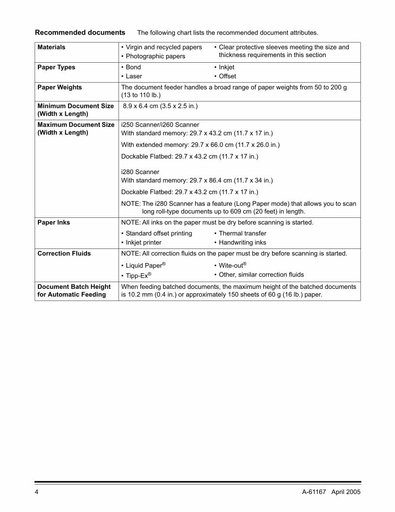
Recommended documents The following chart lists the recommended document attributes.
Materials • Virgin and recycled papers• Photographic papers
• Clear protective sleeves meeting the size and thickness requirements in this section
Paper Types • Bond• Laser
• Inkjet• Offset
Paper Weights The document feeder handles a broad range of paper weights from 50 to 200 g (13 to 110 lb.)
Minimum Document Size (Width x Length)
8.9 x 6.4 cm (3.5 x 2.5 in.)
Maximum Document Size (Width x Length)
i250 Scanner/i260 ScannerWith standard memory: 29.7 x 43.2 cm (11.7 x 17 in.)
With extended memory: 29.7 x 66.0 cm (11.7 x 26.0 in.)
Dockable Flatbed: 29.7 x 43.2 cm (11.7 x 17 in.)
i280 ScannerWith standard memory: 29.7 x 86.4 cm (11.7 x 34 in.)
Dockable Flatbed: 29.7 x 43.2 cm (11.7 x 17 in.)
NOTE: The i280 Scanner has a feature (Long Paper mode) that allows you to scan long roll-type documents up to 609 cm (20 feet) in length.
Paper Inks NOTE: All inks on the paper must be dry before scanning is started.
• Standard offset printing• Inkjet printer
• Thermal transfer• Handwriting inks
Correction Fluids NOTE: All correction fluids on the paper must be dry before scanning is started.
• Liquid Paper®
• Tipp-Ex®
• Wite-out®
• Other, similar correction fluids
Document Batch Height for Automatic Feeding
When feeding batched documents, the maximum height of the batched documents is 10.2 mm (0.4 in.) or approximately 150 sheets of 60 g (16 lb.) paper.

A-61167 April 2005 5
Safety information • When placing the scanner, make sure that the electrical power outlet is located within 1.52 metres (5 feet) of the scanner and is easily accessible.
CAUTION: The scanner and power supply must only be used indoors in a dry location.
• Material Safety Data Sheets (MSDS) for information about chemicals used in Kodak products are available on the Kodak web site at www.kodak.com/go/MSDS. Refer to Appendix B, “Supplies,” for catalog number information.
Warning labels
WARNING: The scanner front panel must be in place and closed during scanner operation.
The imprinter access door must be in place and closed during scanner operation, except when changing the printhead location or replacing the ink cartridge.
When the imprinter access door is removed, DO NOT allow loose clothing, jewelry, hair, or other objects to enter the imprinter area.
User precautions Users and their employer need to observe the common sense precautions applicable to the operation of any machinery. These include, but are not limited to, the following:• Do not wear loose clothing, unbuttoned sleeves, etc.
• Do not wear loose jewelry, bracelets, bulky rings, long necklaces, etc.
• Hair should be kept short, using a hair net if needed or by tying long hair up in a bun.
• Remove all loose objects from the area that could be drawn into the machine.
• Take sufficient breaks to maintain mental alertness.
Supervisors should review their practices and make the compliance with these precautions a part of the job description for the operator of the Kodak i200 Series Scanners and any other mechanical devices.
CAUTION: High voltage. Avoid contact.
CAUTION: Hot surface. Avoid contact.
CAUTION: Moving parts. Avoid contact.
6 A-61167 April 2005
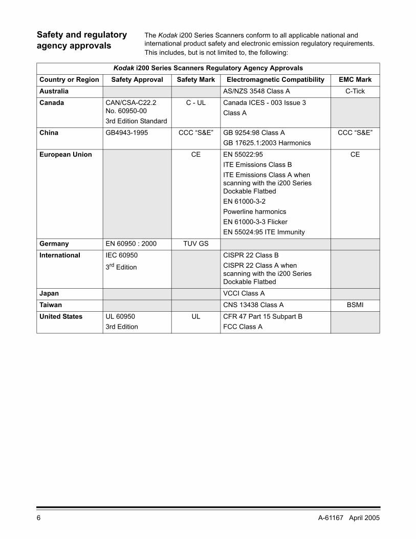
Safety and regulatory agency approvals
The Kodak i200 Series Scanners conform to all applicable national and international product safety and electronic emission regulatory requirements. This includes, but is not limited to, the following:
Kodak i200 Series Scanners Regulatory Agency ApprovalsCountry or Region Safety Approval Safety Mark Electromagnetic Compatibility EMC MarkAustralia AS/NZS 3548 Class A C-Tick
Canada CAN/CSA-C22.2 No. 60950-003rd Edition Standard
C - UL Canada ICES - 003 Issue 3Class A
China GB4943-1995 CCC “S&E” GB 9254:98 Class AGB 17625.1:2003 Harmonics
CCC “S&E”
European Union CE EN 55022:95 ITE Emissions Class BITE Emissions Class A when scanning with the i200 Series Dockable FlatbedEN 61000-3-2 Powerline harmonicsEN 61000-3-3 FlickerEN 55024:95 ITE Immunity
CE
Germany EN 60950 : 2000 TUV GS
International IEC 60950
3rd Edition
CISPR 22 Class BCISPR 22 Class A when scanning with the i200 Series Dockable Flatbed
Japan VCCI Class A
Taiwan CNS 13438 Class A BSMI
United States UL 609503rd Edition
UL CFR 47 Part 15 Subpart BFCC Class A

A-61167 April 2005 7
Environmental information
• The Kodak i200 Series Scanners are designed to meet worldwide environmental requirements.
• The i200 Series Scanners’ power supply cord jacket and the solder on the circuit boards contain lead. Disposal of lead may be regulated due to environmental considerations. For disposal or recycling information, contact your local authorities, or in the U.S.A., visit the Electronics Industry Alliance web site at www.eiae.org.
• Based on a review of the available information, disposal of the ink cartridge would not be regulated under U.S. EPA’s (RCRA), U.S. Clean Water Act (CWA), or both. However, disposal may be subject to state or local landfill, incineration, or recycling requirements.
• Guidelines are available for the disposal of consumable items that are replaced during maintenance or service; follow local regulations or contact Kodak locally for more information.
• The product packaging is recyclable.
• Parts are designed for reuse or recycling.
• The i200 Series Scanners are Energy Star compliant and are shipped from the factory with the default time set to 15 minutes.
Acoustic emission Maschinenlärminformationverordnung — 3, GSGVDer arbeitsplatzbezognene Emissionswert beträgt <70 dB(A).
[Machine Noise Information Ordinance — 3, GSGVThe operator-position noise emission value is <70 dB(A).]
Power system This equipment was designed for connection to IT Power Systems.

8 A-61167 April 2005
EMC statements
United States This equipment has been tested and found to comply with the limits for a Class A digital device pursuant to Part 15 of the FCC rules. These limits are designed to provide reasonable protection against harmful interference when the equipment is operated in a commercial environment. This equipment generates, uses, and can radiate radio frequency energy and, if not installed and used in accordance with the instruction manual, may cause harmful interference to radio communications. Operation of this equipment in a residential area is likely to cause harmful interference in which case the user will be required to correct the interference at his own expense.
Japan This is a Class A product based on the standard of the Voluntary Control Council for interference by information Technology Equipment (VCCI). If this equipment is used in a domestic environment, radio disturbance may arise. When such trouble occurs, the user may be required to take corrective action.
Taiwan WARNING: This is a class A product. In a domestic environment this product may cause radio interference in which case the user may be required to take adequate measures.
People’s Republic of China WARNING: This is a Class A product. In a domestic environment this product may cause radio interference in which case the user may be required to take adequate measures.
European Union (EU) WARNING: This is a Class A product. In a domestic environment this product may cause radio interference in which case the user may be required to take adequate measures.
声明,该产 此为 A 级产品,在生活环境中品可能会造成无线电干扰。在这种情况下,可能需
要用户对其干扰采取切实可行的措施

A-61167 April 2005 9
Installing the Scanner
Site specifications Place the scanner:
• in a clean area with temperature and relative humidity typical of an office environment
CAUTION: The scanner and power supply must only be used indoors in a dry location.
• on a stable, level work surface capable of supporting the following weights:
- i250 Scanner: 12.5 kg (27.5 lb.)
- i260 Scanner: 13.9 kg (30.5 lb.)
- i280 Scanner: 13.9 kg (30.5 lb.)
- i250 Scanner with optional flatbed accessory: 19.8 kg (43.5 lb.)
- i260 Scanner with optional flatbed accessory: 21.2 kg (46.5 lb.)
- i280 Scanner with optional flatbed accessory: 21.2 kg (46.5 lb.)
• within 1.52 metres (5 feet) of an electrical power outlet
NOTE: For more information about the scanner specifications, refer to Appendix A, Specifications.

10 A-61167 April 2005
System requirements
Minimum system configuration
To operate the scanner, the following minimum configuration is required.
NOTES: The actual performance of the system depends upon the scanning application, choice of scanning parameters, and the host computer configuration. If the scanner is not performing at the optimal speed, a faster computer and/or more RAM may be necessary to obtain the rated throughput.
• IBM PC (or compatible) with a Pentium III 1 GHz processor
- i260 Scanner: for scanning at 300 dpi with deskew, you will need at least a 1.8 GHz processor for bi-tonal scanning or a 2.5 GHz processor for color scanning.
- i280 Scanner: for scanning at 300 dpi with deskew, you will need at least a 2.5 GHz processor for bi-tonal scanning or a 3.2 GHz processor for color scanning.
• Microsoft Windows 98SE, Windows Millennium Edition (Me), Windows 2000, or Windows XP
• 100 MB of available hard disk space (200 MB is recommended)
• 128 MB of RAM
• Monitor (VGA)
• Mouse
Recommended system configuration
To operate the scanner at its optimum speed, the following configuration (or better) is recommended.
NOTE: The actual performance of the system depends on the scanning application, choice of scanning parameters, and the host computer configuration.
• IBM PC (or compatible) with a Pentium IV 3.2 GHz processor
• Microsoft Windows 98SE, Windows Millennium Edition (Me), Windows 2000, or Windows XP
• 200 MB of available hard disk space
• 512 MB of RAM
• Additional memory (SODIMM) installed in the scanner
- i250 Scanner: up to 256 MB of memory is allowed
- i260 Scanner: up to 256 MB of memory is allowed
- i280 Scanner: up to 512 MB of memory is allowed
• Monitor (VGA)
• Mouse
A-61167 April 2005 11
Unpacking the scanner The scanner box contains the following items:
• Kodak i200 Series Scanner
• Input tray
• Output tray
• Power supply
• Power cord(s)
• Installation CD
• Kodak Capture Software Lite CD
• Read Me Now sheet
• User’s Guide (printed English version; User’s Guide .pdf files in nine other languages are included on the Installation CD)
• Registration sheet
• Cleaning materials
• Calibration target pack
NOTE: Save all packing materials for possible future use.
Registering your scanner
It is very important that you register your scanner so Kodak can provide you with the best possible service and support. Registering your scanner will help us provide you with firmware and hardware updates as they become available.
NOTE: The scanner must be registered before any service support can be provided.
You can register your scanner’s new equipment warranty online at www.kodak.com/go/DIwarrantyregistration.
For more information about Kodak’s service and support options, contact your reseller of Kodak Document Imaging products or visit us on the web at www.kodak.com/go/DIserviceandsupport.
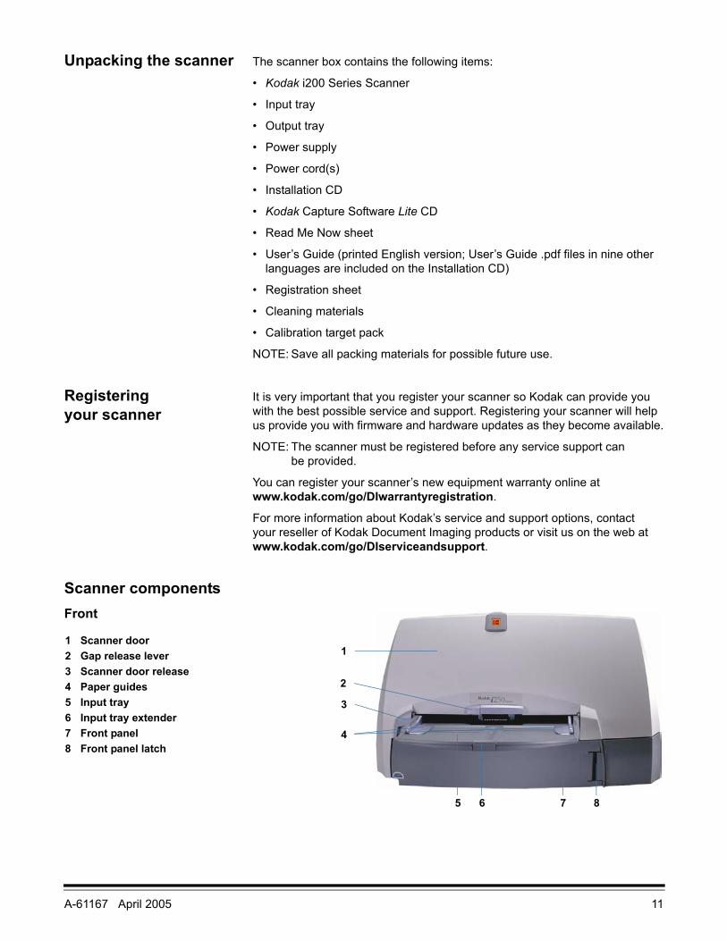
Scanner componentsFront
1 Scanner door2 Gap release lever3 Scanner door release4 Paper guides5 Input tray6 Input tray extender7 Front panel8 Front panel latch
1
4
7 85 6
3
2
12 A-61167 April 2005
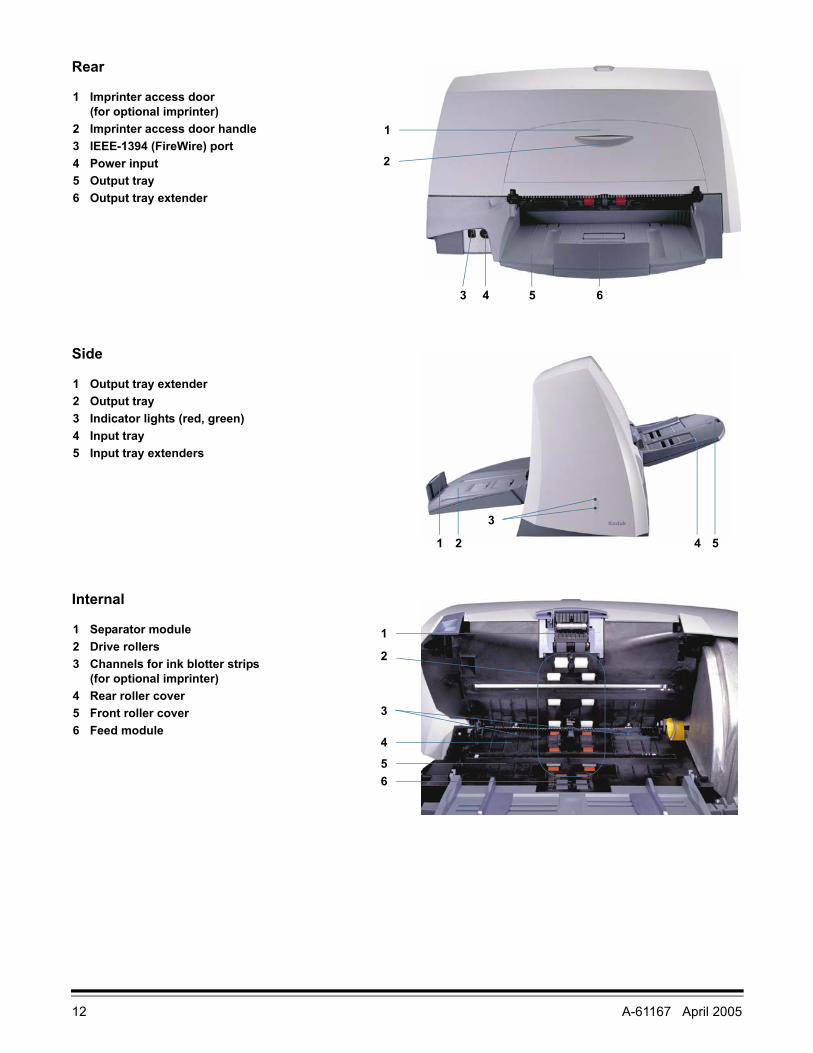
Rear
Side
Internal
1 Imprinter access door (for optional imprinter)
2 Imprinter access door handle3 IEEE-1394 (FireWire) port4 Power input5 Output tray6 Output tray extender
5 63 4
1
2
1 Output tray extender2 Output tray3 Indicator lights (red, green)4 Input tray5 Input tray extenders
1 2 4 5
3
1 Separator module2 Drive rollers3 Channels for ink blotter strips
(for optional imprinter)4 Rear roller cover5 Front roller cover6 Feed module
2
3
4
56
1

A-61167 April 2005 13
Making connections Follow the instructions for installing the IEEE-1394 (FireWire) card and the Kodak Driver Software before you plug the scanner into the host computer.
IMPORTANT: You must install the software on the host computer before you install the scanner.
Installing the IEEE-1394 (FireWire) card in the host computer
An IEEE-1394 six-pin connector is provided on the rear panel of the scanner for IEEE-1394 (FireWire) connectivity.
1. Install the IEEE-1394 (FireWire) card in the host computer as described by the instructions included with the card.
IMPORTANT: Use proper precautions to avoid static when you install the IEEE-1394 (FireWire) card in your computer.
2. Power up the host computer after the IEEE-1394 (FireWire) card installation is complete.
Installing the Kodak Driver software
1. Insert the Kodak i200 Series Installation CD in the CD-ROM drive.
The installation program starts automatically.
2. Follow the onscreen instructions to install the TWAIN and ISIS drivers and the Kodak Scan Validation Tool.
Installing the IEEE-1394 (FireWire) cable
1. Attach the beaded end of the IEEE-1394 (FireWire) cable to the IEEE-1394 port on the back of the scanner.
WARNING: Make sure that the position of the IEEE-1394 (FireWire) cable connector end correlates to the IEEE-1394 port configuration before you plug the cable in. Damage to the scanner will occur if the cable is attached in the wrong position.
IMPORTANT: Only use the IEEE-1394 cable that is supplied with the i200 Series Scanner.
14 A-61167 April 2005
2. Attach the other end of the IEEE-1394 (FireWire) cable to the host computer.
WARNING: Make sure that the position of the IEEE-1394 (FireWire) cable connector end correlates to the IEEE-1394 port configuration before you plug the cable in. Damage to the scanner will occur if the cable is attached in the wrong position.
IMPORTANT: The i200 Series Scanner should be the only item plugged in to the IEEE-1394 (FireWire) card on the host computer.
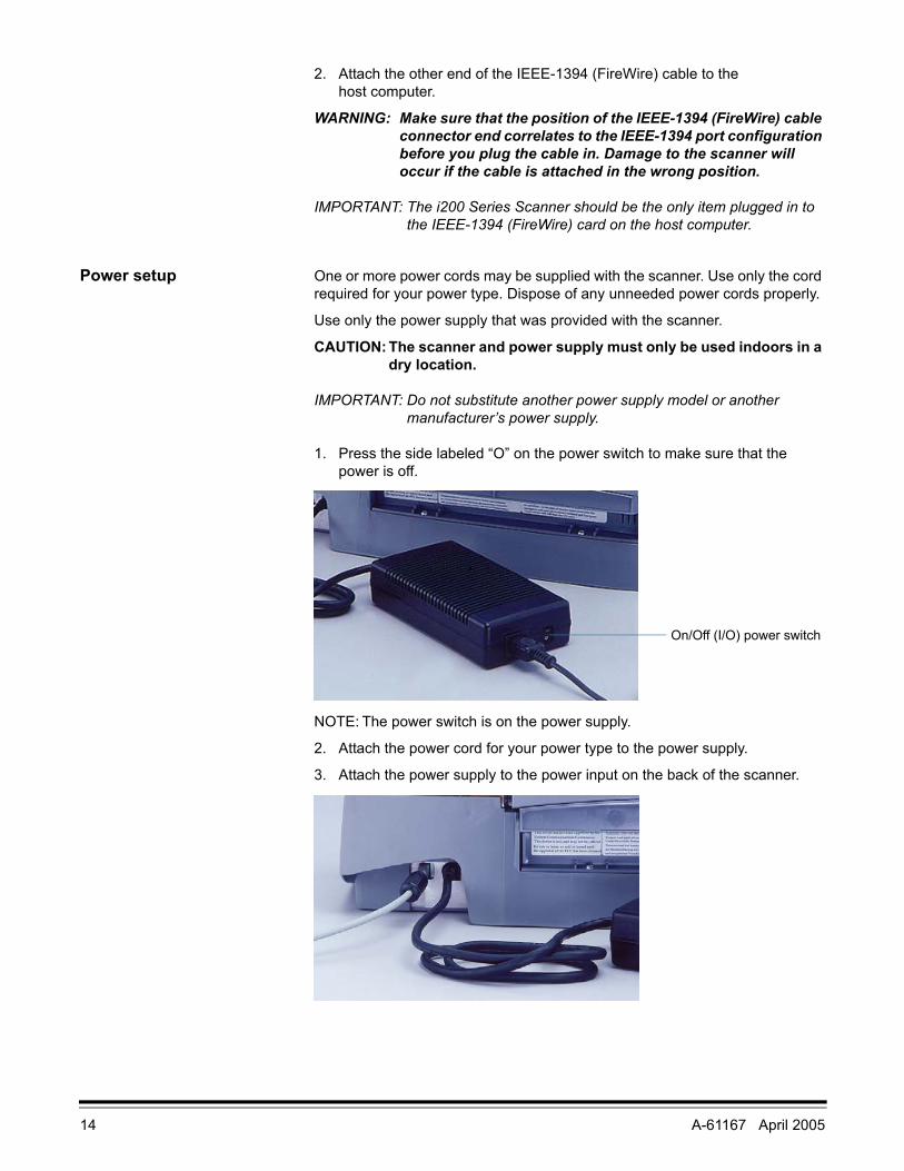
Power setup One or more power cords may be supplied with the scanner. Use only the cord required for your power type. Dispose of any unneeded power cords properly.
Use only the power supply that was provided with the scanner.
CAUTION: The scanner and power supply must only be used indoors in a dry location.
IMPORTANT: Do not substitute another power supply model or another manufacturer’s power supply.
1. Press the side labeled “O” on the power switch to make sure that the power is off.
NOTE: The power switch is on the power supply.
2. Attach the power cord for your power type to the power supply.
3. Attach the power supply to the power input on the back of the scanner.
On/Off (I/O) power switch

A-61167 April 2005 15
4. Plug the power cord into a power outlet.
NOTE: Make sure that the power outlet is located within 1.52 metres (5 feet) of the scanner and is easily accessible.
5. Press the side labeled “I” on the power switch to power up the scanner.
After you power up the scanner, the red and green indicator lights will illuminate. After approximately one minute, both lights go out. When the green indicator light comes back on, the scanner is installed and ready to begin scanning. However, the host computer may require a few more seconds to detect the scanner.
For best calibration and scanning results, allow the scanner lamps to warm up for at least three minutes.
• If you are installing the scanner on a computer that is running Windows 2000, the following screen may appear.
Select Yes. Kodak has successfully tested the i200 Series Scanners with Windows 2000.
Your scanner is now installed.
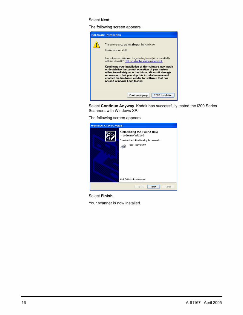
• If you are installing the scanner on a computer that is running Windows XP, the following screen may appear.
16 A-61167 April 2005
Select Next.
The following screen appears.
Select Continue Anyway. Kodak has successfully tested the i200 Series Scanners with Windows XP.
The following screen appears.
Select Finish.
Your scanner is now installed.
A-61167 April 2005 17
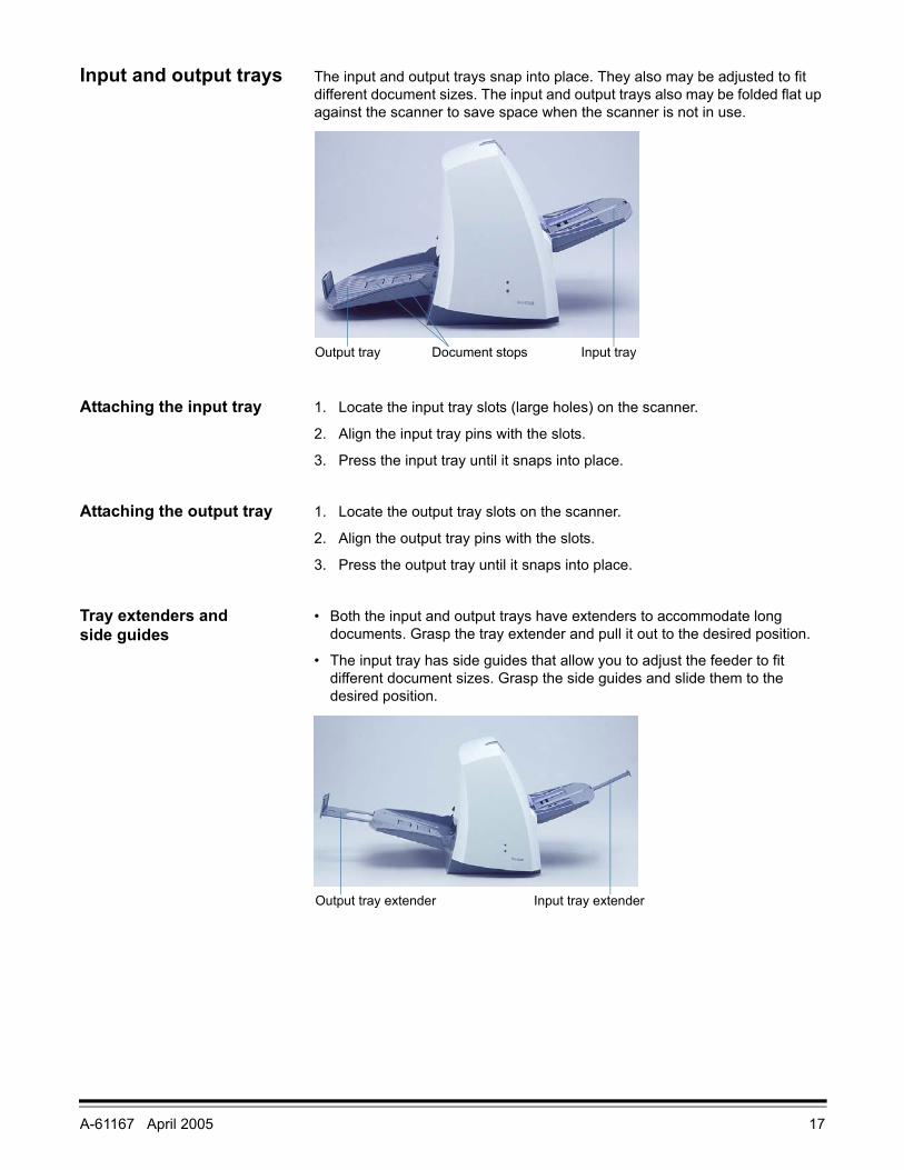
Input and output trays The input and output trays snap into place. They also may be adjusted to fit different document sizes. The input and output trays also may be folded flat up against the scanner to save space when the scanner is not in use.
Attaching the input tray 1. Locate the input tray slots (large holes) on the scanner.
2. Align the input tray pins with the slots.
3. Press the input tray until it snaps into place.
Attaching the output tray 1. Locate the output tray slots on the scanner.
2. Align the output tray pins with the slots.
3. Press the output tray until it snaps into place.
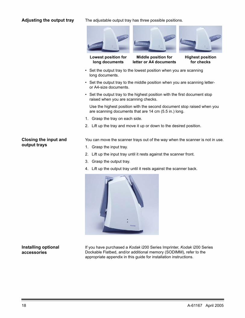
Tray extenders and side guides
• Both the input and output trays have extenders to accommodate long documents. Grasp the tray extender and pull it out to the desired position.
• The input tray has side guides that allow you to adjust the feeder to fit different document sizes. Grasp the side guides and slide them to the desired position.
Input trayOutput tray Document stops
Input tray extenderOutput tray extender
18 A-61167 April 2005
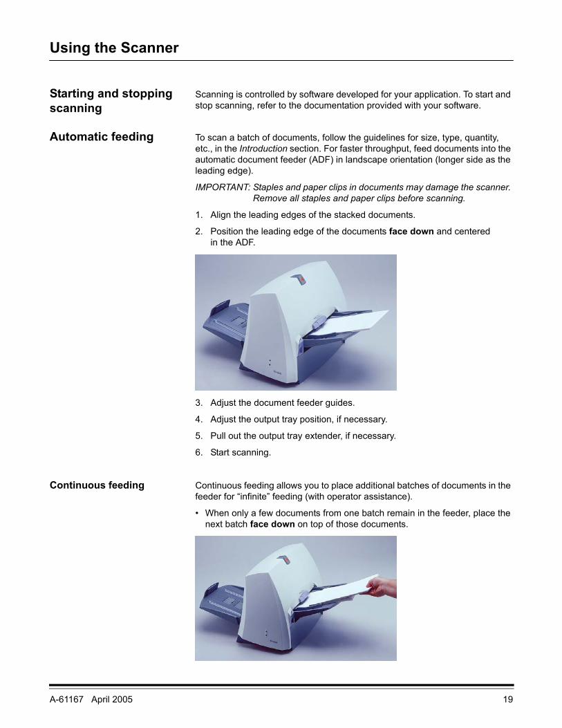
Adjusting the output tray The adjustable output tray has three possible positions.
• Set the output tray to the lowest position when you are scanning long documents.
• Set the output tray to the middle position when you are scanning letter- or A4-size documents.
• Set the output tray to the highest position with the first document stop raised when you are scanning checks.
Use the highest position with the second document stop raised when you are scanning documents that are 14 cm (5.5 in.) long.
1. Grasp the tray on each side.
2. Lift up the tray and move it up or down to the desired position.
Closing the input and output trays
You can move the scanner trays out of the way when the scanner is not in use.
1. Grasp the input tray.
2. Lift up the input tray until it rests against the scanner front.
3. Grasp the output tray.
4. Lift up the output tray until it rests against the scanner back.
Installing optional accessories
If you have purchased a Kodak i200 Series Imprinter, Kodak i200 Series Dockable Flatbed, and/or additional memory (SODIMM), refer to the appropriate appendix in this guide for installation instructions.
Lowest position for long documents
Middle position for letter or A4 documents
Highest position for checks
A-61167 April 2005 19
Using the Scanner
Starting and stopping scanning
Scanning is controlled by software developed for your application. To start and stop scanning, refer to the documentation provided with your software.
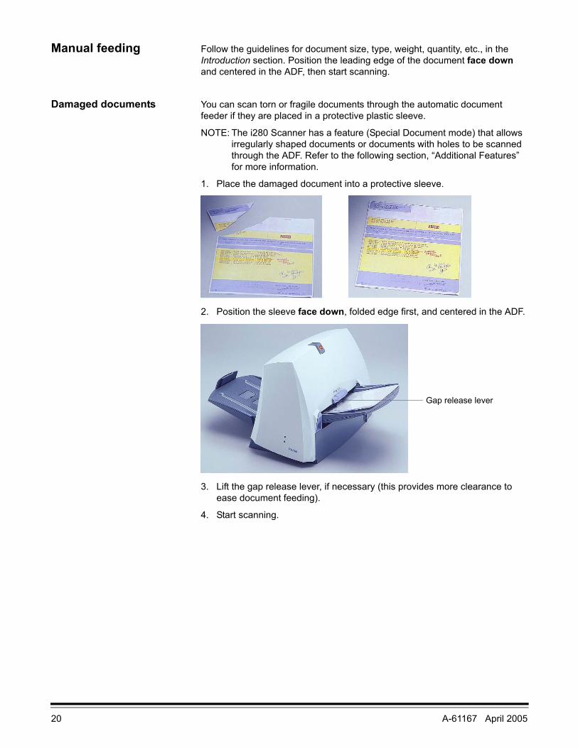
Automatic feeding To scan a batch of documents, follow the guidelines for size, type, quantity, etc., in the Introduction section. For faster throughput, feed documents into the automatic document feeder (ADF) in landscape orientation (longer side as the leading edge).
IMPORTANT: Staples and paper clips in documents may damage the scanner. Remove all staples and paper clips before scanning.
1. Align the leading edges of the stacked documents.
2. Position the leading edge of the documents face down and centered in the ADF.
3. Adjust the document feeder guides.
4. Adjust the output tray position, if necessary.
5. Pull out the output tray extender, if necessary.
6. Start scanning.
Continuous feeding Continuous feeding allows you to place additional batches of documents in the feeder for “infinite” feeding (with operator assistance).
• When only a few documents from one batch remain in the feeder, place the next batch face down on top of those documents.
20 A-61167 April 2005
Manual feeding Follow the guidelines for document size, type, weight, quantity, etc., in the Introduction section. Position the leading edge of the document face down and centered in the ADF, then start scanning.
Damaged documents You can scan torn or fragile documents through the automatic document feeder if they are placed in a protective plastic sleeve.
NOTE: The i280 Scanner has a feature (Special Document mode) that allows irregularly shaped documents or documents with holes to be scanned through the ADF. Refer to the following section, “Additional Features” for more information.
1. Place the damaged document into a protective sleeve.
2. Position the sleeve face down, folded edge first, and centered in the ADF.
3. Lift the gap release lever, if necessary (this provides more clearance to ease document feeding).
4. Start scanning.
Gap release lever
A-61167 April 2005 21
Additional features Following are additional scanning capabilities that allow you to scan more document types faster and with better results. With the exception of Perfect Page with iThresholding, these features are for the i280 Scanner only:
• Long Paper mode
• Special Document mode
• Perfect Page with iThresholding - for all i200 Series Scanners
• Toggle patch
Long Paper mode Long Paper mode allows you to scan documents that exceed the 34-inch maximum length that the scanner normally handles. You can scan documents that are up to 609 cm (20 feet) long at resolutions of up to 300 dpi with Long Paper mode. These document types include document rolls (e.g., EKG charts, chart recorder rolls, and other roll-type documents).
The scanned document is delivered in multiple images. You can specify the length and width of the images in the fixed cropping option in your scanning application. The recommended segment size is 10 to 12 inches.
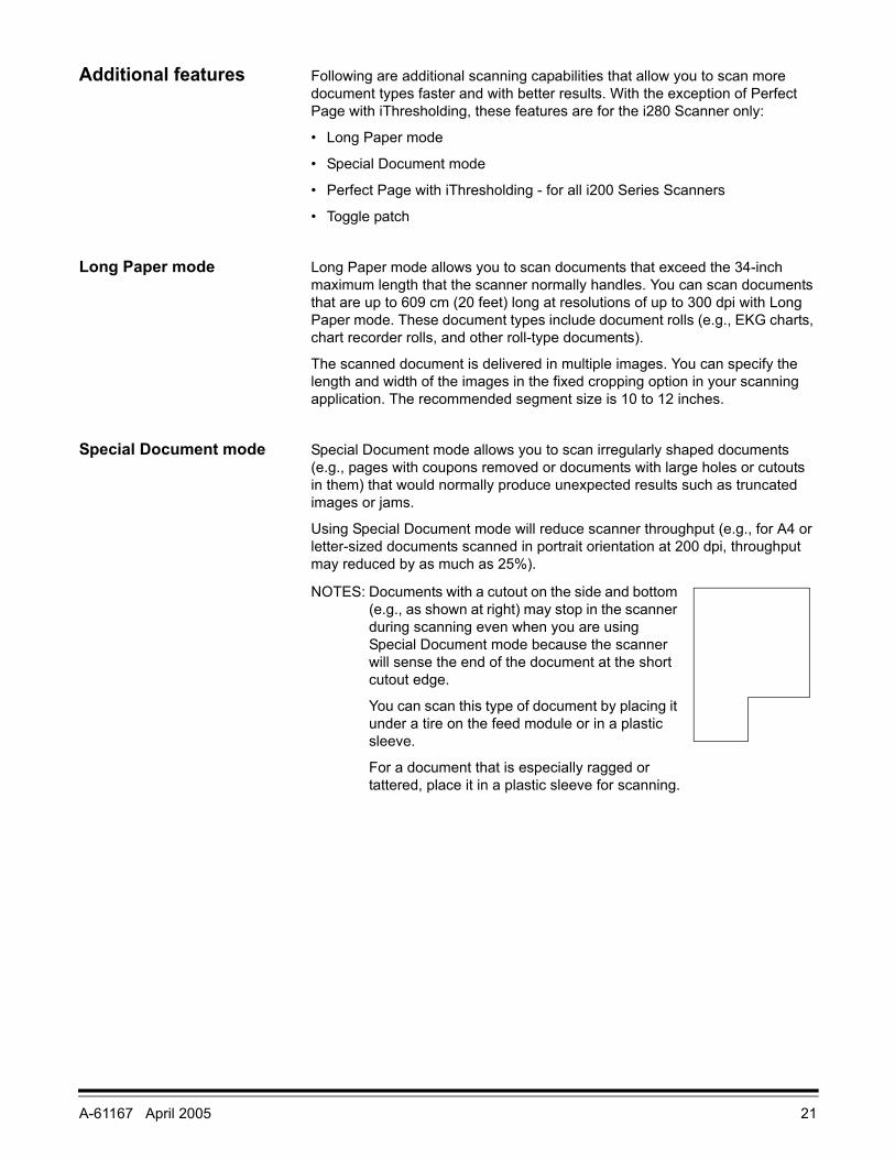
Special Document mode Special Document mode allows you to scan irregularly shaped documents (e.g., pages with coupons removed or documents with large holes or cutouts in them) that would normally produce unexpected results such as truncated images or jams.
Using Special Document mode will reduce scanner throughput (e.g., for A4 or letter-sized documents scanned in portrait orientation at 200 dpi, throughput may reduced by as much as 25%).
NOTES: Documents with a cutout on the side and bottom (e.g., as shown at right) may stop in the scanner during scanning even when you are using Special Document mode because the scanner will sense the end of the document at the short cutout edge.
You can scan this type of document by placing it under a tire on the feed module or in a plastic sleeve.
For a document that is especially ragged or tattered, place it in a plastic sleeve for scanning.
22 A-61167 April 2005
Perfect Page with iThresholding
Perfect Page with iThresholding is essential when you are scanning mixed batches of documents of varied contrast in background and/or text. Brightness is automatically adjusted for each individual document for highlighting, low contrast, and lightweight paper — situations that previously required manual adjustments.
Using the iThresholding feature, the scanner dynamically evaluates each document in the batch to determine the optimal threshold value to produce the highest quality image.
The iThresholding feature delivers high-quality images from a large range of both poor- and high-contrast documents and reduces the need to pre-sort, rescan, and perform post-image processing. You get better image and text legibility, smoother lines, minimal to no artifacts, and fewer shaded areas with minimal or no user intervention.
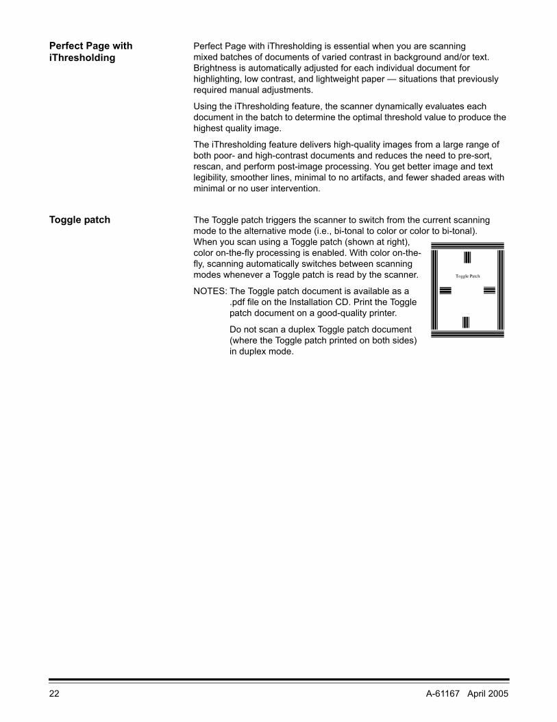
Toggle patch The Toggle patch triggers the scanner to switch from the current scanning mode to the alternative mode (i.e., bi-tonal to color or color to bi-tonal).
When you scan using a Toggle patch (shown at right), color on-the-fly processing is enabled. With color on-the-fly, scanning automatically switches between scanning modes whenever a Toggle patch is read by the scanner.
NOTES: The Toggle patch document is available as a .pdf file on the Installation CD. Print the Toggle patch document on a good-quality printer.
Do not scan a duplex Toggle patch document (where the Toggle patch printed on both sides) in duplex mode.

A-61167 April 2005 23
Maintenance
Cleaning the scanner The scanner will collect dust and other debris during routine scanning. For optimal scanner performance, follow the detailed cleaning instructions in this section and clean the feed module tires, separator module tires, imaging guides, transport area, and paper path at least once per week. Clean the scanner and paper path daily if you are scanning carbonless paper or newsprint, or if you are using the imprinter.
Use only these cleaning materials:
IMPORTANT: Staticide Wipes contain isopropanol which can cause eye irritation and dry skin. Wash your hands with soap and water after performing maintenance procedures. Refer to the Material Data Safety Sheet (MSDS) for more information. The MSDS is available on the Kodak web site at www.kodak.com/go/MSDS.
Allow all tires to dry completely before using the scanner.
NOTES: The use of any other cleaning materials could damage your scanner.
Use fresh cleaning material unless otherwise indicated.
In addition to the recommended cleaning supplies, you may use a vacuum cleaner to remove debris from the scanner.
Some debris from the rubber tires on the feed module and separator module is normal. Tire debris does not always mean that the tires are worn or damaged. After cleaning, inspect the tires for wear and replace the separator module or feed module if necessary.
To order cleaning supplies, refer to Appendix B, Supplies and Accessories.
Item CAT No.Kodak Digital Science Roller Cleaning Pads (24) 853 5981
Staticide Wipes for Kodak Scanners (144) 896 5519
Kodak Digital Science Transport Cleaning Sheets (50) 169 0783
24 A-61167 April 2005
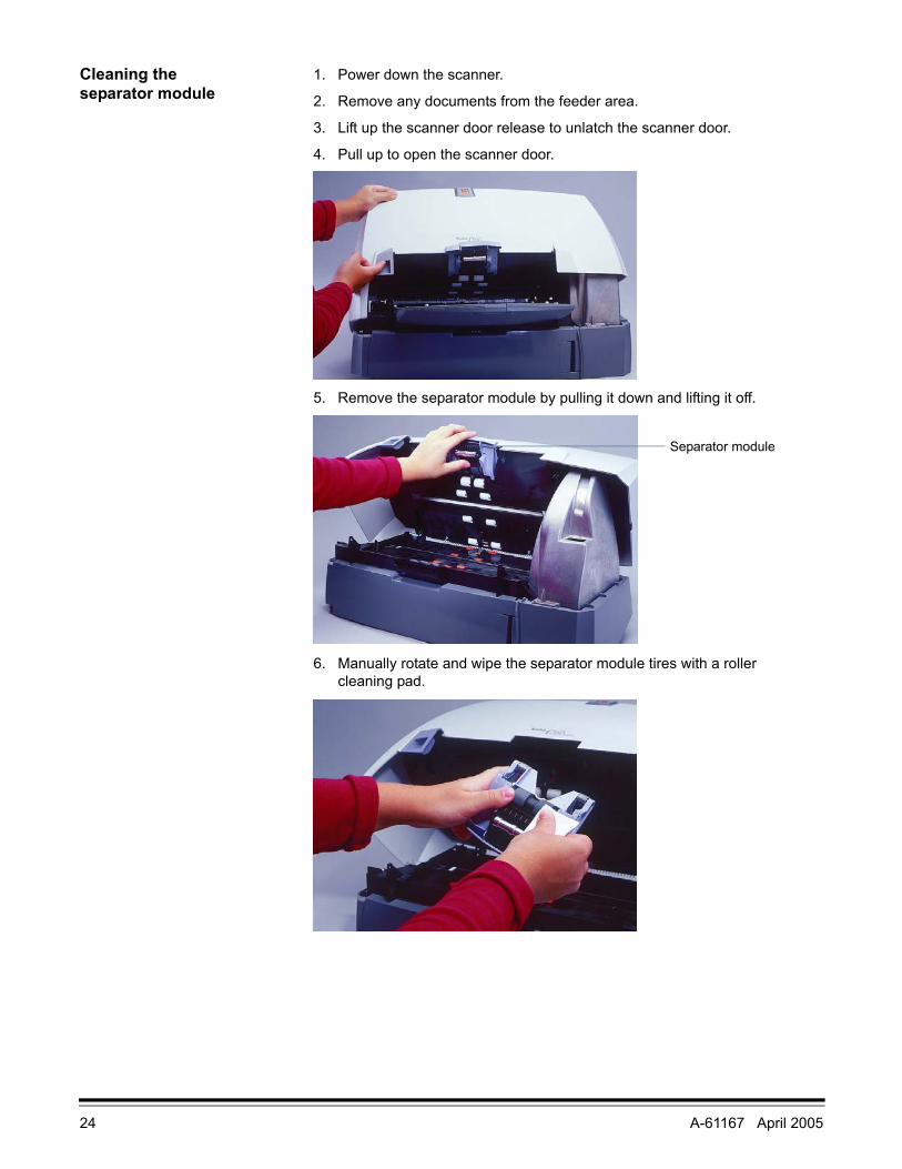
Cleaning the separator module
1. Power down the scanner.
2. Remove any documents from the feeder area.
3. Lift up the scanner door release to unlatch the scanner door.
4. Pull up to open the scanner door.
5. Remove the separator module by pulling it down and lifting it off.
6. Manually rotate and wipe the separator module tires with a roller cleaning pad.
Separator module
A-61167 April 2005 25
7. Inspect the tires.
If the separator module tires show signs of wear or damage, replace the tires or the separator module.
8. Insert the separator module and align the shaft ends.
9. Press until the separator module clicks into place.
10. Go to the next section to clean the feed module.
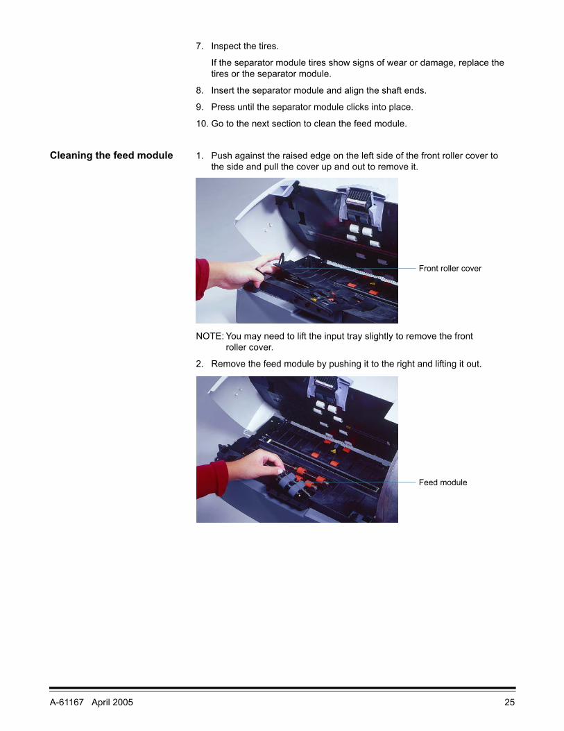
Cleaning the feed module 1. Push against the raised edge on the left side of the front roller cover to the side and pull the cover up and out to remove it.
NOTE: You may need to lift the input tray slightly to remove the front roller cover.
2. Remove the feed module by pushing it to the right and lifting it out.
Front roller cover
Feed module
26 A-61167 April 2005
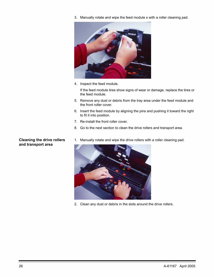
3. Manually rotate and wipe the feed module s with a roller cleaning pad.
4. Inspect the feed module.
If the feed module tires show signs of wear or damage, replace the tires or the feed module.
5. Remove any dust or debris from the tray area under the feed module and the front roller cover.
6. Insert the feed module by aligning the pins and pushing it toward the right to fit it into position.
7. Re-install the front roller cover.
8. Go to the next section to clean the drive rollers and transport area.
Cleaning the drive rollers and transport area
1. Manually rotate and wipe the drive rollers with a roller cleaning pad.
2. Clean any dust or debris in the slots around the drive rollers.
A-61167 April 2005 27
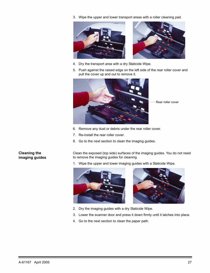
3. Wipe the upper and lower transport areas with a roller cleaning pad.
4. Dry the transport area with a dry Staticide Wipe.
5. Push against the raised edge on the left side of the rear roller cover and pull the cover up and out to remove it.
6. Remove any dust or debris under the rear roller cover.
7. Re-install the rear roller cover.
8. Go to the next section to clean the imaging guides.
Cleaning the imaging guides
Clean the exposed (top side) surfaces of the imaging guides. You do not need to remove the imaging guides for cleaning.
1. Wipe the upper and lower imaging guides with a Staticide Wipe.
2. Dry the imaging guides with a dry Staticide Wipe.
3. Lower the scanner door and press it down firmly until it latches into place.
4. Go to the next section to clean the paper path.
Rear roller cover

28 A-61167 April 2005
Cleaning the paper path 1. Remove the wrapping from the Transport Cleaning Sheet.
2. Adjust the paper feeder guides to fit the cleaning sheet.
3. Feed the cleaning sheet (adhesive side up) through the scanner in portrait orientation until all residue is removed from the drive rollers.
4. Adjust the feeder guides to fit, then feed the cleaning sheet (adhesive side up) through the scanner in landscape orientation until all residue is removed from the drive rollers.
5. Using the same cleaning sheet, repeat Steps 3 and 4, but feed the cleaning sheet through the scanner with the adhesive side down until all residue is removed from the drive rollers.
NOTE: When a cleaning sheet gets very dirty, discard it and use a new one.
Replacing parts Customer-replacement parts (feed module, separator module, pre-separation pad, roller tires, and installation instructions) are available in the following kits:
Use only these replacement parts in your scanner.
The expected life of customer-replaceable parts is shown below.
• Kodak Separator Module for i200 Series Scanners: 200,000 document pages
• Kodak Feed Module for i200 Series Scanners: 500,000 document pages
NOTES: The composition of the tire materials was engineered to provide the ultimate in feeding reliability across the broadest range of document types, sizes, and thicknesses. Expected life figures are offered as guidelines for operations that follow the recommended scanner cleaning procedures in this section and that scan document types within the recommended paper types (refer to “Preparing documents for scanning” in the Introduction section).
Your experience may vary. Certain paper types (such as carbonless paper or newsprint), failure to clean regularly, and/or use of non-recommended cleaning solvents can shorten tire life.
Tire life may be reduced due to a long transport timeout setting.
To order replacement parts, refer to Appendix B, Supplies and Accessories.
Item CAT No.Kodak Feeder Consumables Kit for i200 Series Scanners (1 complete feed module, 1 complete separator module, 2 pre-separation pads, 24 tires)
124 1066
Kodak Extra-Large Feeder Consumables Kit for i200 Series Scanners (5 complete feed modules, 5 complete separator modules, 10 pre-separation pads, 120 tires)
821 5808
Kodak Imaging Guide Set (1 upper, 1 lower) 120 0278
A-61167 April 2005 29
Calibrating the scanner Calibration optimizes the optical system in your scanner in order to achieve the best overall quality of scanned images. Frequent calibration is not needed or recommended.
NOTE: The screens shown in this section are for the TWAIN driver. Your screens may be different.
1. Allow the lamps to warm up for three minutes.
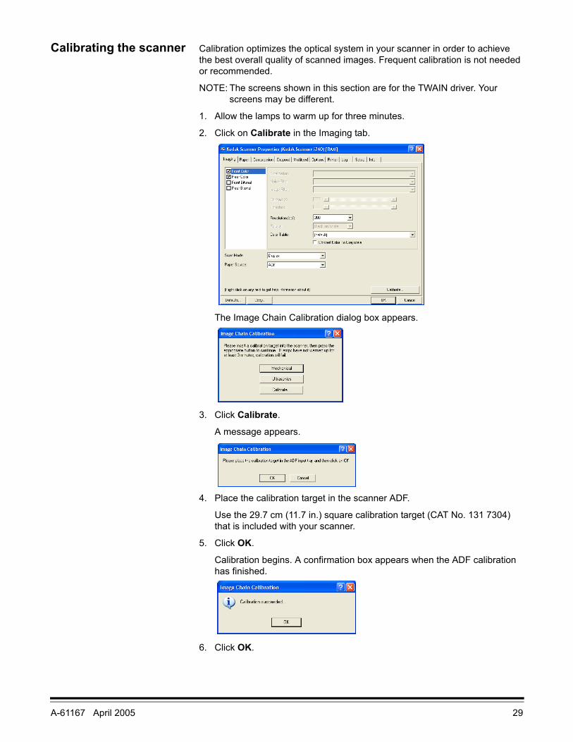
2. Click on Calibrate in the Imaging tab.
The Image Chain Calibration dialog box appears.
3. Click Calibrate.
A message appears.
4. Place the calibration target in the scanner ADF.
Use the 29.7 cm (11.7 in.) square calibration target (CAT No. 131 7304) that is included with your scanner.
5. Click OK.
Calibration begins. A confirmation box appears when the ADF calibration has finished.
6. Click OK.
30 A-61167 April 2005
Troubleshooting
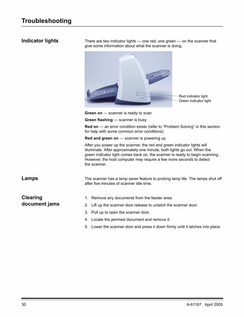
Indicator lights There are two indicator lights — one red, one green — on the scanner that give some information about what the scanner is doing.
Green on — scanner is ready to scan
Green flashing — scanner is busy
Red on — an error condition exists (refer to “Problem Solving” in this section for help with some common error conditions)
Red and green on — scanner is powering up
After you power up the scanner, the red and green indicator lights will illuminate. After approximately one minute, both lights go out. When the green indicator light comes back on, the scanner is ready to begin scanning. However, the host computer may require a few more seconds to detect the scanner.
Lamps The scanner has a lamp saver feature to prolong lamp life. The lamps shut off after five minutes of scanner idle time.
Clearing document jams
1. Remove any documents from the feeder area.
2. Lift up the scanner door release to unlatch the scanner door.
3. Pull up to open the scanner door.
4. Locate the jammed document and remove it.
5. Lower the scanner door and press it down firmly until it latches into place.
Green indicator lightRed indicator light
A-61167 April 2005 31
Adjusting the separator module tension
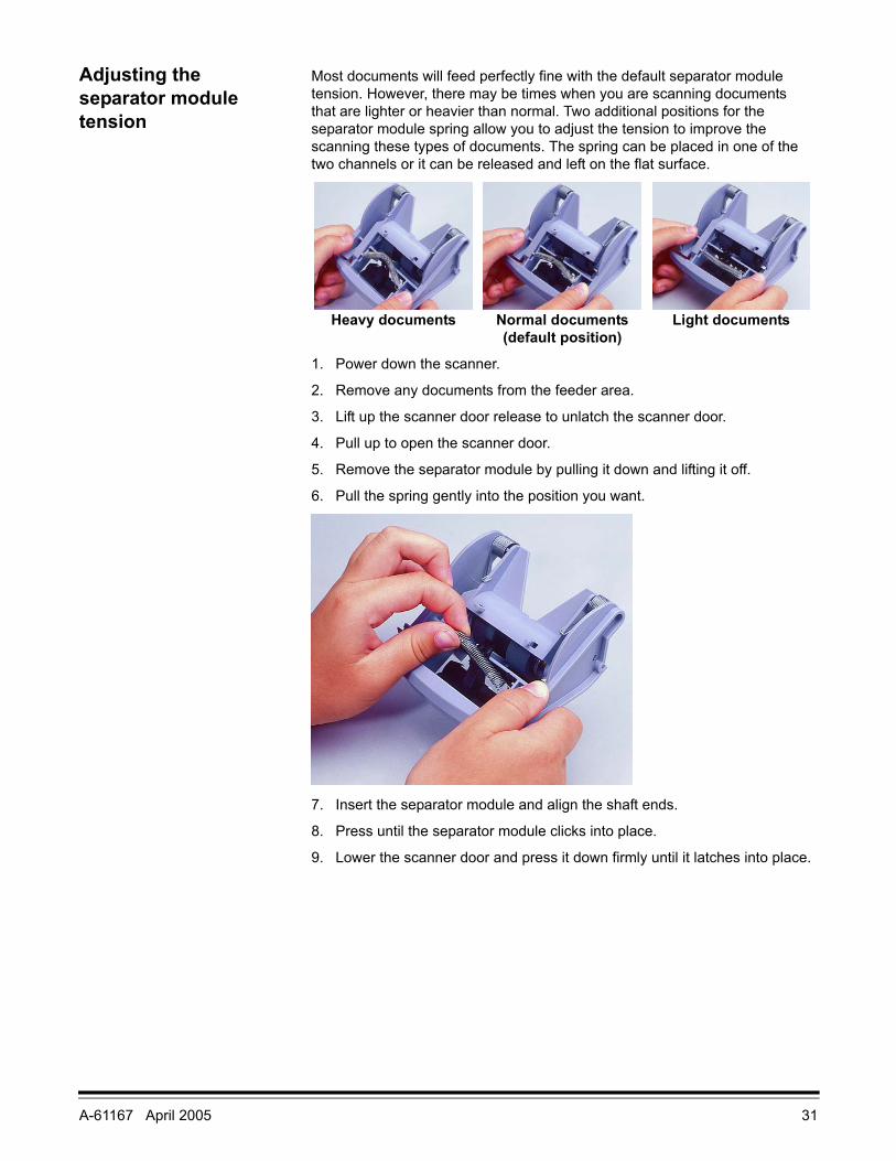
Most documents will feed perfectly fine with the default separator module tension. However, there may be times when you are scanning documents that are lighter or heavier than normal. Two additional positions for the separator module spring allow you to adjust the tension to improve the scanning these types of documents. The spring can be placed in one of the two channels or it can be released and left on the flat surface.
1. Power down the scanner.
2. Remove any documents from the feeder area.
3. Lift up the scanner door release to unlatch the scanner door.
4. Pull up to open the scanner door.
5. Remove the separator module by pulling it down and lifting it off.
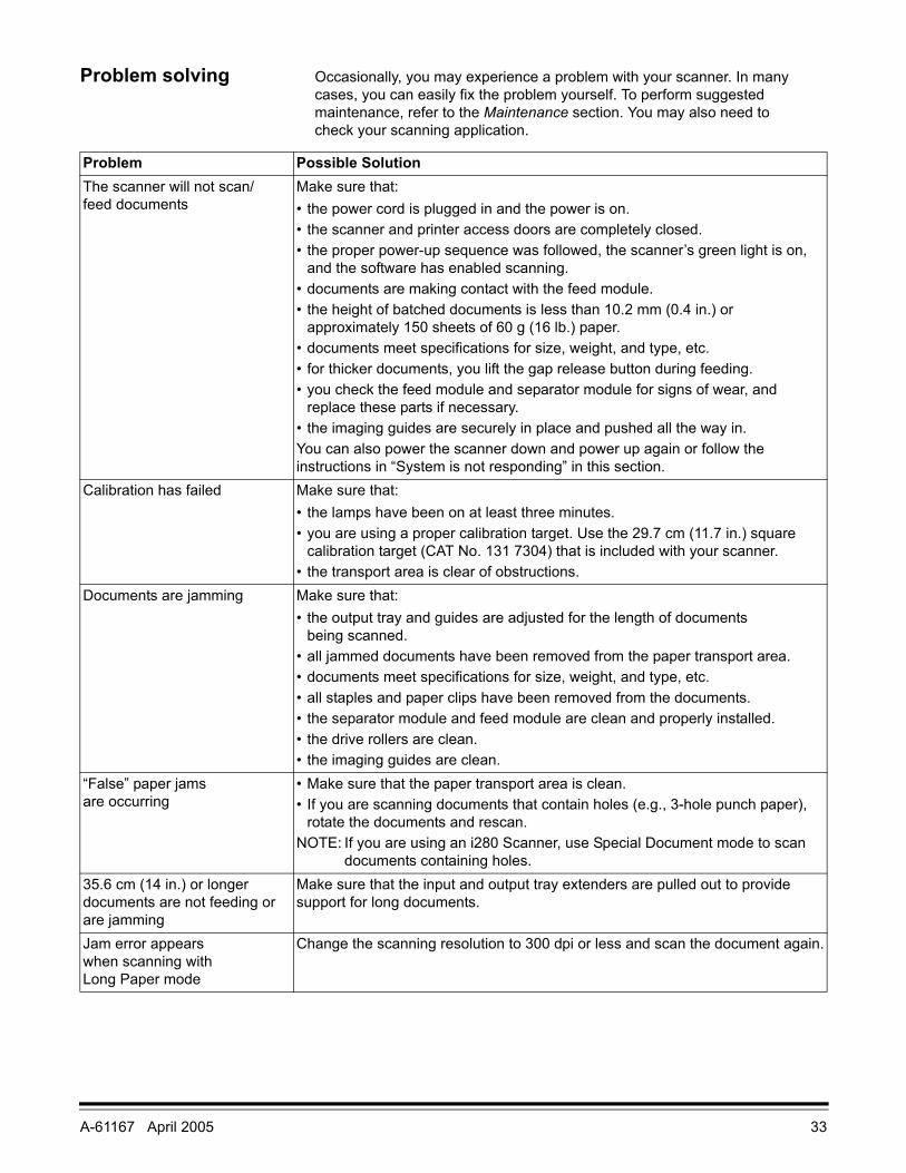
6. Pull the spring gently into the position you want.
7. Insert the separator module and align the shaft ends.
8. Press until the separator module clicks into place.
9. Lower the scanner door and press it down firmly until it latches into place.
Heavy documents Normal documents(default position)
Light documents

32 A-61167 April 2005
System is not responding
If the scanner and/or host computer are not responding, perform the following steps.
1. Power down the computer.
2. Power down the scanner.
3. Disconnect the IEEE-1394 (FireWire) cable from the IEEE-1394 port on the back of the scanner.
4. Power up the computer.
5. Power up the scanner.
After you power up the scanner, the red and green indicator lights will illuminate. After approximately one minute, both lights go out. When the green indicator light comes back on, the scanner is ready to begin scanning. However, the host computer may require a few more seconds to detect the scanner.
6. Wait until the scanner light is green and no longer in the power-up mode.
7. Attach the IEEE-1394 (FireWire) cable to the IEEE-1394 port on the back of the scanner.
8. Wait a few moments for the host computer’s operating system to recognize the scanner.
The scanner is now ready to use.
Color image quality Color image quality is highly subjective. Here are some things to consider when scanning in color:
• The difference in the color outputs of scanners, printers, and monitors can affect the perception of the scanned document.
• Computer displays and printer output can vary from model to model, and from manufacturer to manufacturer. An image may be acceptable on one display and unacceptable on another.
• Area lighting (fluorescent, natural, incandescent) can affect color perception.
• The appearance of a colored area within an image can be perceived differently, based on what surrounds it.
• The characteristics and condition of a document can have an impact on color consistency.
• Color requirements may differ between environments (e.g., in a business document environment, images are generally viewed on a monitor, whereas in a “print on demand” environment, scanned images are printed).
To ensure that your scanner is delivering the best image:
• Clean the scanner. Contamination within the scanner degrades image quality. (Refer to the Maintenance section for cleaning information.)
• Calibrate the scanner occasionally and make sure that the calibration target is clean and unwrinkled.
A-61167 April 2005 33
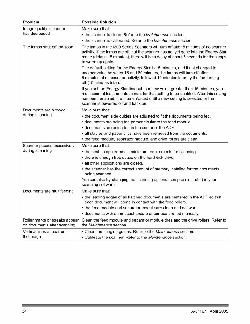
Problem solving Occasionally, you may experience a problem with your scanner. In many cases, you can easily fix the problem yourself. To perform suggested maintenance, refer to the Maintenance section. You may also need to check your scanning application.
Problem Possible SolutionThe scanner will not scan/feed documents
Make sure that:• the power cord is plugged in and the power is on.• the scanner and printer access doors are completely closed.• the proper power-up sequence was followed, the scanner’s green light is on,
and the software has enabled scanning.• documents are making contact with the feed module.• the height of batched documents is less than 10.2 mm (0.4 in.) or
approximately 150 sheets of 60 g (16 lb.) paper.• documents meet specifications for size, weight, and type, etc.• for thicker documents, you lift the gap release button during feeding.• you check the feed module and separator module for signs of wear, and
replace these parts if necessary.• the imaging guides are securely in place and pushed all the way in.You can also power the scanner down and power up again or follow the instructions in “System is not responding” in this section.
Calibration has failed Make sure that:• the lamps have been on at least three minutes.• you are using a proper calibration target. Use the 29.7 cm (11.7 in.) square
calibration target (CAT No. 131 7304) that is included with your scanner.• the transport area is clear of obstructions.
Documents are jamming Make sure that:• the output tray and guides are adjusted for the length of documents
being scanned.• all jammed documents have been removed from the paper transport area.• documents meet specifications for size, weight, and type, etc.• all staples and paper clips have been removed from the documents.• the separator module and feed module are clean and properly installed.• the drive rollers are clean.• the imaging guides are clean.
“False” paper jams are occurring
• Make sure that the paper transport area is clean.• If you are scanning documents that contain holes (e.g., 3-hole punch paper),
rotate the documents and rescan.NOTE: If you are using an i280 Scanner, use Special Document mode to scan
documents containing holes.35.6 cm (14 in.) or longer documents are not feeding or are jamming
Make sure that the input and output tray extenders are pulled out to provide support for long documents.
Jam error appears when scanning with Long Paper mode
Change the scanning resolution to 300 dpi or less and scan the document again.
34 A-61167 April 2005
Problem Possible SolutionImage quality is poor or has decreased
Make sure that:• the scanner is clean. Refer to the Maintenance section.• the scanner is calibrated. Refer to the Maintenance section.
The lamps shut off too soon The lamps in the i200 Series Scanners will turn off after 5 minutes of no scanner activity. If the lamps are off, but the scanner has not yet gone into the Energy Star mode (default 15 minutes), there will be a delay of about 5 seconds for the lamps to warm up again.The default setting for the Energy Star is 15 minutes, and if not changed to another value between 16 and 60 minutes, the lamps will turn off after 5 minutes of no scanner activity, followed 10 minutes later by the fan turning off (15 minutes total).If you set the Energy Star timeout to a new value greater than 15 minutes, you must scan at least one document for that setting to be enabled. After this setting has been enabled, it will be enforced until a new setting is selected or the scanner is powered off and back on.
Documents are skewed during scanning
Make sure that:• the document side guides are adjusted to fit the documents being fed.• documents are being fed perpendicular to the feed module.• documents are being fed in the center of the ADF.• all staples and paper clips have been removed from the documents.• the feed module, separator module, and drive rollers are clean.
Scanner pauses excessively during scanning
Make sure that:• the host computer meets minimum requirements for scanning.• there is enough free space on the hard disk drive.• all other applications are closed.• the scanner has the correct amount of memory installed for the documents
being scanned.You can also try changing the scanning options (compression, etc.) in your scanning software.
Documents are multifeeding Make sure that:• the leading edges of all batched documents are centered in the ADF so that
each document will come in contact with the feed rollers.• the feed module and separator module are clean and not worn.• documents with an unusual texture or surface are fed manually.
Roller marks or streaks appear on documents after scanning
Clean the feed module and separator module tires and the drive rollers. Refer to the Maintenance section.
Vertical lines appear on the image
• Clean the imaging guides. Refer to the Maintenance section.• Calibrate the scanner. Refer to the Maintenance section.

A-61167 April 2005 35
Transporting the scanner
If it becomes necessary to transport the scanner after installation, you must repack the scanner using the original packaging materials. If you do not have the original packaging materials, contact your supplier.
1. Power down the computer.
2. Power down the scanner.
3. Disconnect the power cord from the back of the scanner.
4. Disconnect the IEEE-1394 (FireWire) cable from the IEEE-1394 port on the back of the scanner.
5. Place the foam end caps on each end of the scanner.
6. Place the scanner in the box.
7. Place the power cord and power supply in the box.
8. Tape down the input and output trays to secure them.
9. Close the box.
The scanner is now ready for moving.
A-61167 April 2005 A-1
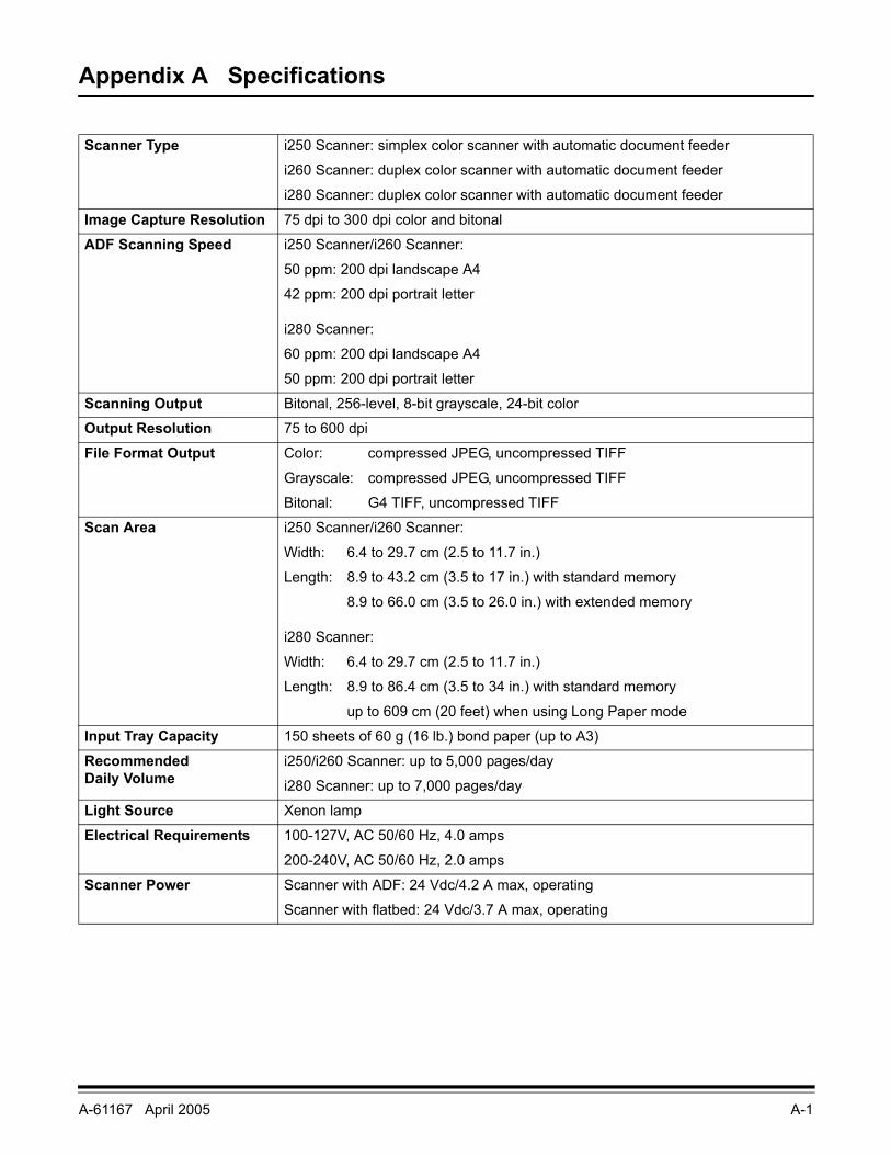
Appendix A Specifications
Scanner Type i250 Scanner: simplex color scanner with automatic document feeder
i260 Scanner: duplex color scanner with automatic document feeder
i280 Scanner: duplex color scanner with automatic document feeder
Image Capture Resolution 75 dpi to 300 dpi color and bitonal
ADF Scanning Speed i250 Scanner/i260 Scanner:
50 ppm: 200 dpi landscape A4
42 ppm: 200 dpi portrait letter
i280 Scanner:
60 ppm: 200 dpi landscape A4
50 ppm: 200 dpi portrait letter
Scanning Output Bitonal, 256-level, 8-bit grayscale, 24-bit color
Output Resolution 75 to 600 dpi
File Format Output Color: compressed JPEG, uncompressed TIFF
Grayscale: compressed JPEG, uncompressed TIFF
Bitonal: G4 TIFF, uncompressed TIFF
Scan Area i250 Scanner/i260 Scanner:
Width: 6.4 to 29.7 cm (2.5 to 11.7 in.)
Length: 8.9 to 43.2 cm (3.5 to 17 in.) with standard memory
8.9 to 66.0 cm (3.5 to 26.0 in.) with extended memory
i280 Scanner:
Width: 6.4 to 29.7 cm (2.5 to 11.7 in.)
Length: 8.9 to 86.4 cm (3.5 to 34 in.) with standard memory
up to 609 cm (20 feet) when using Long Paper mode
Input Tray Capacity 150 sheets of 60 g (16 lb.) bond paper (up to A3)
Recommended Daily Volume
i250/i260 Scanner: up to 5,000 pages/day
i280 Scanner: up to 7,000 pages/day
Light Source Xenon lamp
Electrical Requirements 100-127V, AC 50/60 Hz, 4.0 amps
200-240V, AC 50/60 Hz, 2.0 amps
Scanner Power Scanner with ADF: 24 Vdc/4.2 A max, operating
Scanner with flatbed: 24 Vdc/3.7 A max, operating
A-2 A-61167 April 2005
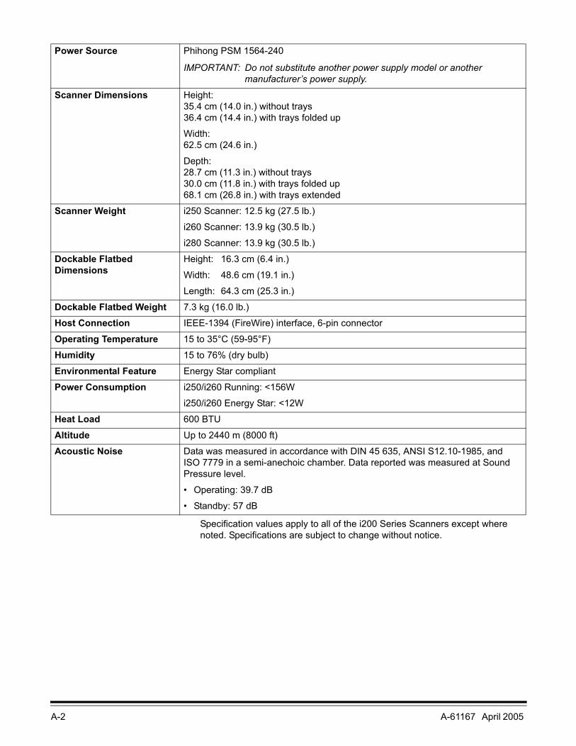
Specification values apply to all of the i200 Series Scanners except where noted. Specifications are subject to change without notice.
Power Source Phihong PSM 1564-240
IMPORTANT: Do not substitute another power supply model or another manufacturer’s power supply.
Scanner Dimensions Height: 35.4 cm (14.0 in.) without trays36.4 cm (14.4 in.) with trays folded up
Width:62.5 cm (24.6 in.)
Depth: 28.7 cm (11.3 in.) without trays30.0 cm (11.8 in.) with trays folded up68.1 cm (26.8 in.) with trays extended
Scanner Weight i250 Scanner: 12.5 kg (27.5 lb.)
i260 Scanner: 13.9 kg (30.5 lb.)
i280 Scanner: 13.9 kg (30.5 lb.)
Dockable Flatbed Dimensions
Height: 16.3 cm (6.4 in.)
Width: 48.6 cm (19.1 in.)
Length: 64.3 cm (25.3 in.)
Dockable Flatbed Weight 7.3 kg (16.0 lb.)
Host Connection IEEE-1394 (FireWire) interface, 6-pin connector
Operating Temperature 15 to 35°C (59-95°F)
Humidity 15 to 76% (dry bulb)
Environmental Feature Energy Star compliant
Power Consumption i250/i260 Running: <156W
i250/i260 Energy Star: <12W
Heat Load 600 BTU
Altitude Up to 2440 m (8000 ft)
Acoustic Noise Data was measured in accordance with DIN 45 635, ANSI S12.10-1985, and ISO 7779 in a semi-anechoic chamber. Data reported was measured at Sound Pressure level.
• Operating: 39.7 dB
• Standby: 57 dB

A-61167 April 2005 B-1
Appendix B Supplies and Accessories
Contact your scanner supplier to order supplies.
Item CAT No.Kodak i200 Series Dockable Flatbed 130 5390
Kodak i200 Series Imprinter 892 7964
Kodak Feeder Consumables Kit for i200 Series Scanners(1 complete feed module, 1 complete separator module, 2 pre-separation pads, 24 tires)
124 1066
Kodak Extra-Large Feeder Consumables Kit for i200 Series Scanners(5 complete feed modules, 5 complete separator modules, 10 pre-separation pads, 120 tires)
821 5808
Kodak Printer Ink Blotters for i200 Series Scanners (60) 840 5425
Kodak Printer Ink Cartridge Carrier for i200/i800/3000/4000/7000/9000 Series Scanners 826 7486
Kodak Printer Ink Cartridges for i200/i800/3000/4000/7000/9000 Series Scanners (10) 135 5155
Kodak Imaging Guide Set 120 0278
Kodak Digital Science Transport Cleaning Sheets (50) 169 0783
Kodak Digital Science Roller Cleaning Pads (24) 853 5981
Staticide Wipes for Kodak Scanners (144) 896 5519
Kodak Calibration Kit for i200 Series Scanners 131 7304

A-61167 April 2005 C-1
Appendix C Kodak i200 Series Imprinter
The Kodak i200 Series Imprinter adds imprinting capability to your Kodak i200 Series Scanner. The imprinter prints a date, time, fixed string, and/or sequential number on document backs. Purchase the imprinter separately (CAT No. 892 7964).
The imprinter operates at full scanner speed, and prints on the document after scanning on the rear side of the document (top side as placed in the input tray). Imprinting is controlled through software.
IMPORTANT: Clean the scanner's internal components daily when you use the imprinter.
WARNING: The imprinter access door must be in place and closed during scanner operation, except when changing the printhead location or replacing the ink cartridge.
When the imprinter access door is removed, DO NOT allow loose clothing, jewelry, hair, or other objects to enter the imprinter area.
Contents of the imprinter kit
The Kodak i200 Series Imprinter kit contains the following items:
• Imprinter board
• Mounting bracket
• Thumbscrews (4)
• Imprinter cable
• Ink cartridge carrier
• Ink cartridge
• Ink blotters (2)
• Installation instructions
C-2 A-61167 April 2005
Installing the imprinter
Removing the circuit board cover
1. Make sure that the scanner is powered down and there are no documents in the feeder area.
2. Disconnect the power cord from the back of the scanner.
3. Disconnect the IEEE-1394 (FireWire) cable from the IEEE-1394 port on the back of the scanner.
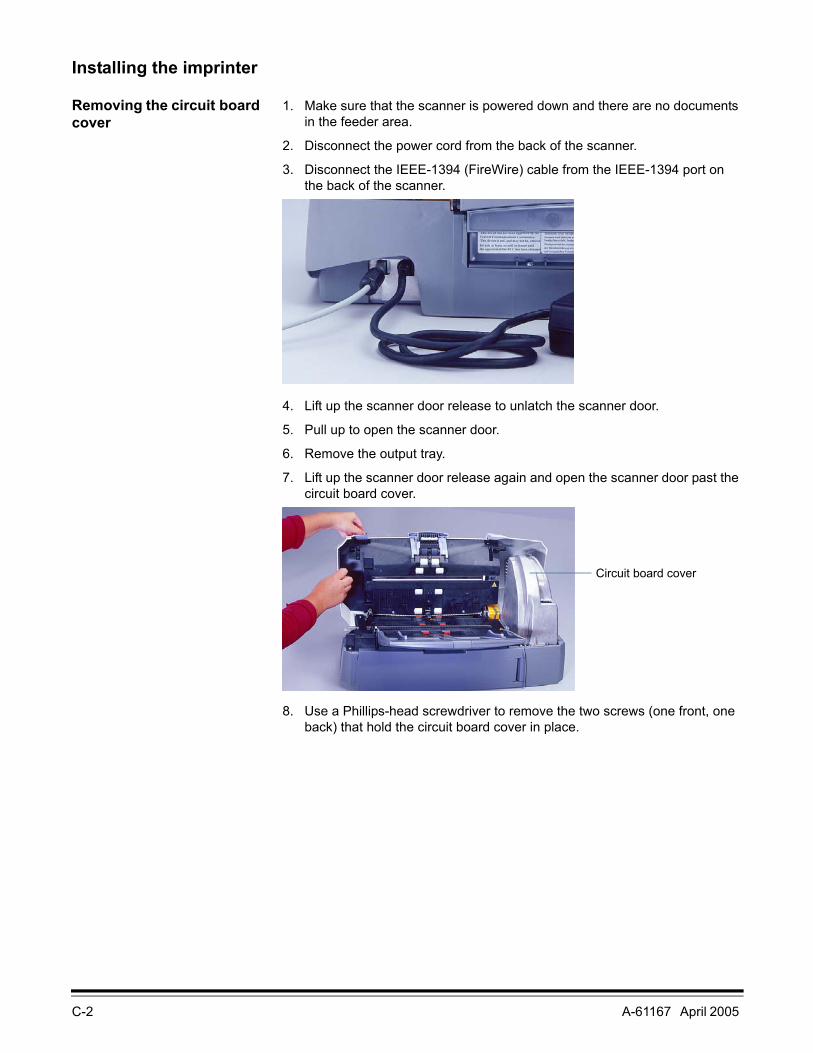
4. Lift up the scanner door release to unlatch the scanner door.
5. Pull up to open the scanner door.
6. Remove the output tray.
7. Lift up the scanner door release again and open the scanner door past the circuit board cover.
8. Use a Phillips-head screwdriver to remove the two screws (one front, one back) that hold the circuit board cover in place.
Circuit board cover

A-61167 April 2005 C-3
9. Lift up the circuit board cover and remove it.
10. Go to the next section to attach the imprinter board and cable.
Attaching the imprinter board and cable
The imprinter board is first attached to a mounting bracket which is connected to the main control board, then the imprinter cable is plugged in.
IMPORTANT: Use proper precautions to avoid static when you install the imprinter card.
1. Place the imprinter board on the circuit board mounting bracket.
C-4 A-61167 April 2005
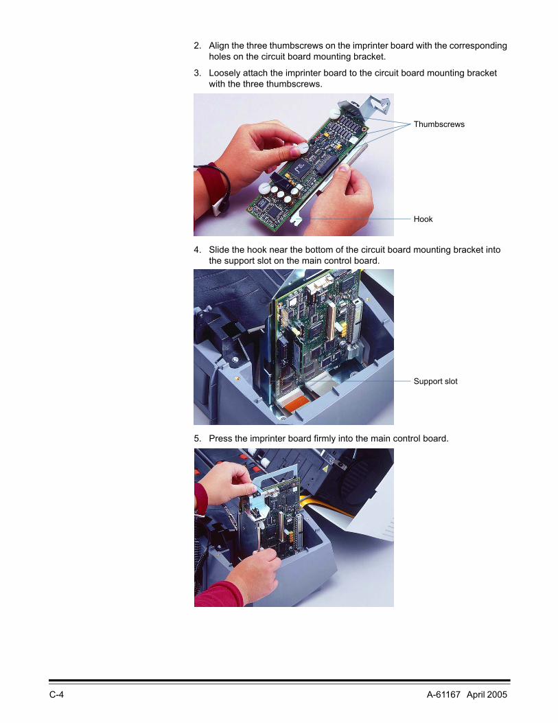
2. Align the three thumbscrews on the imprinter board with the corresponding holes on the circuit board mounting bracket.
3. Loosely attach the imprinter board to the circuit board mounting bracket with the three thumbscrews.
4. Slide the hook near the bottom of the circuit board mounting bracket into the support slot on the main control board.
5. Press the imprinter board firmly into the main control board.
Thumbscrews
Hook
Support slot
A-61167 April 2005 C-5
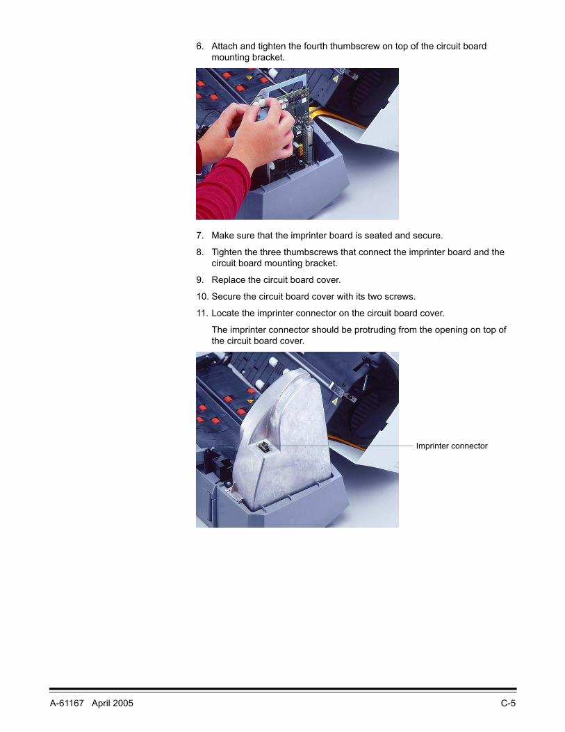
6. Attach and tighten the fourth thumbscrew on top of the circuit board mounting bracket.
7. Make sure that the imprinter board is seated and secure.
8. Tighten the three thumbscrews that connect the imprinter board and the circuit board mounting bracket.
9. Replace the circuit board cover.
10. Secure the circuit board cover with its two screws.
11. Locate the imprinter connector on the circuit board cover.
The imprinter connector should be protruding from the opening on top of the circuit board cover.
Imprinter connector
C-6 A-61167 April 2005
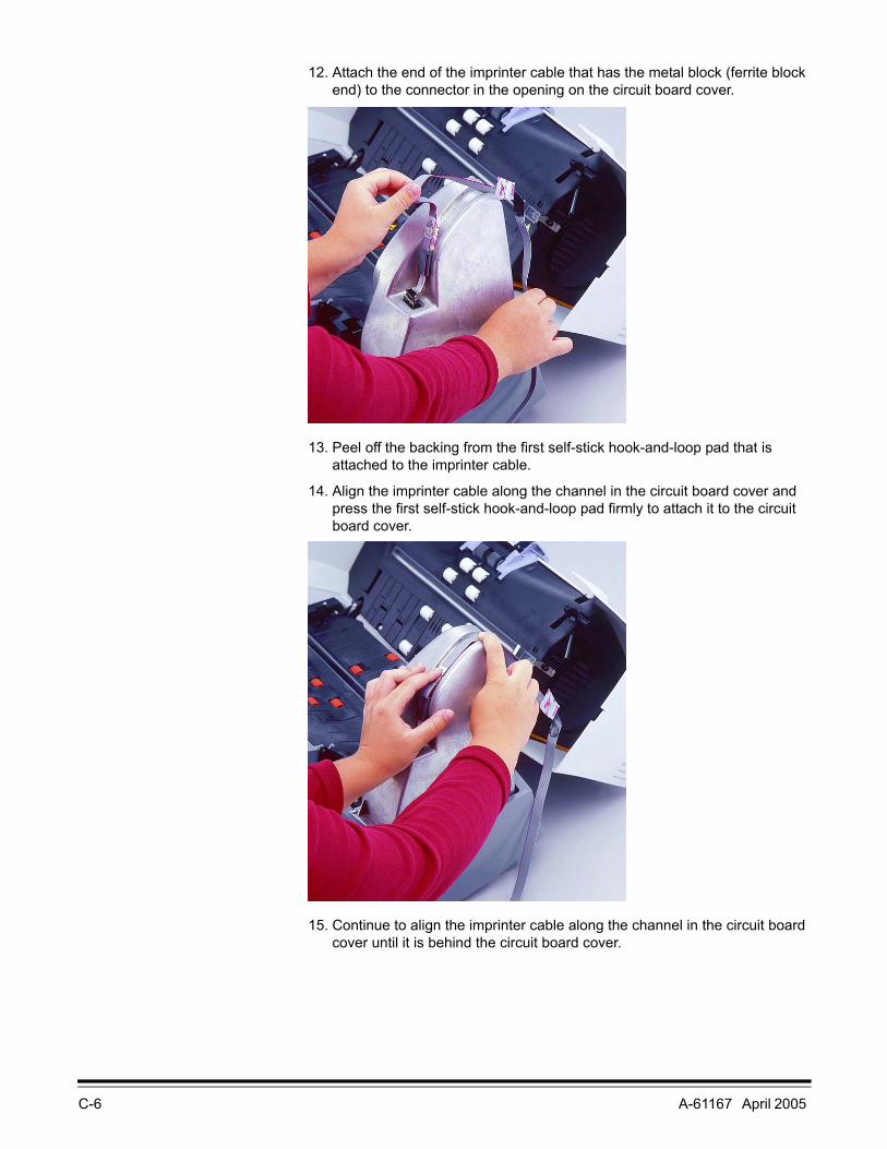
12. Attach the end of the imprinter cable that has the metal block (ferrite block end) to the connector in the opening on the circuit board cover.
13. Peel off the backing from the first self-stick hook-and-loop pad that is attached to the imprinter cable.
14. Align the imprinter cable along the channel in the circuit board cover and press the first self-stick hook-and-loop pad firmly to attach it to the circuit board cover.
15. Continue to align the imprinter cable along the channel in the circuit board cover until it is behind the circuit board cover.
A-61167 April 2005 C-7
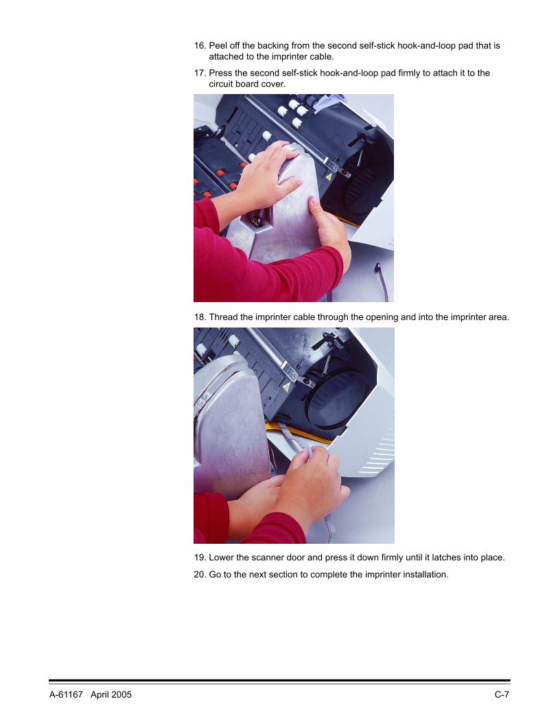
16. Peel off the backing from the second self-stick hook-and-loop pad that is attached to the imprinter cable.
17. Press the second self-stick hook-and-loop pad firmly to attach it to the circuit board cover.
18. Thread the imprinter cable through the opening and into the imprinter area.
19. Lower the scanner door and press it down firmly until it latches into place.
20. Go to the next section to complete the imprinter installation.
C-8 A-61167 April 2005
Completing the imprinter installation
After installing the imprinter board and cable, you must seat the cable in its supports and install the ink cartridge and carrier.
IMPORTANT: An ink cartridge must be in the ink cartridge carrier in order for the imprinter to be recognized.
1. Locate the imprinter access door on the back of the scanner.
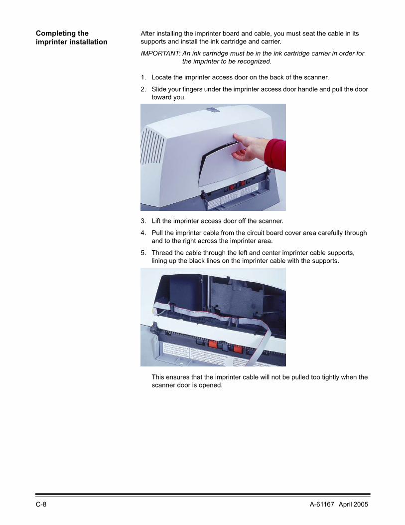
2. Slide your fingers under the imprinter access door handle and pull the door toward you.
3. Lift the imprinter access door off the scanner.
4. Pull the imprinter cable from the circuit board cover area carefully through and to the right across the imprinter area.
5. Thread the cable through the left and center imprinter cable supports, lining up the black lines on the imprinter cable with the supports.
This ensures that the imprinter cable will not be pulled too tightly when the scanner door is opened.
A-61167 April 2005 C-9
6. Remove the ink cartridge from its packaging.
NOTE: Detailed information about installing ink cartridges may be found later in this chapter.
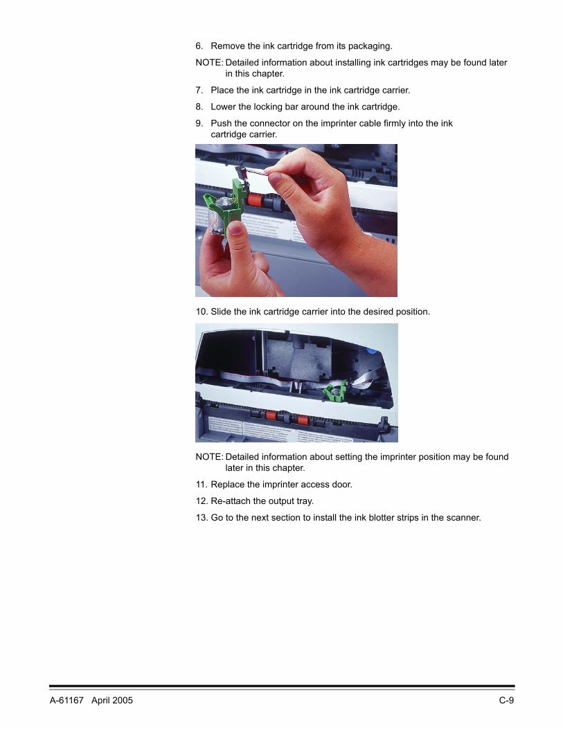
7. Place the ink cartridge in the ink cartridge carrier.
8. Lower the locking bar around the ink cartridge.
9. Push the connector on the imprinter cable firmly into the ink cartridge carrier.
10. Slide the ink cartridge carrier into the desired position.
NOTE: Detailed information about setting the imprinter position may be found later in this chapter.
11. Replace the imprinter access door.
12. Re-attach the output tray.
13. Go to the next section to install the ink blotter strips in the scanner.
C-10 A-61167 April 2005
Installing the ink blotter strips
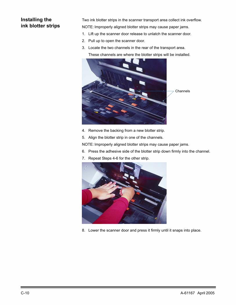
Two ink blotter strips in the scanner transport area collect ink overflow.
NOTE: Improperly aligned blotter strips may cause paper jams.
1. Lift up the scanner door release to unlatch the scanner door.
2. Pull up to open the scanner door.
3. Locate the two channels in the rear of the transport area.
These channels are where the blotter strips will be installed.
4. Remove the backing from a new blotter strip.
5. Align the blotter strip in one of the channels.
NOTE: Improperly aligned blotter strips may cause paper jams.
6. Press the adhesive side of the blotter strip down firmly into the channel.
7. Repeat Steps 4-6 for the other strip.
8. Lower the scanner door and press it firmly until it snaps into place.
Channels
A-61167 April 2005 C-11
Installing an ink cartridge
To install the ink cartridge:
1. Locate the imprinter access door on the back of the scanner.
2. Slide your fingers under the imprinter access door handle and pull the door toward you.
3. Lift the imprinter access door off the scanner.
4. Slide the ink cartridge carrier out of its position.
5. Raise the locking bar.
6. Remove the empty ink cartridge, if one is present.
NOTE: Dispose of empty ink cartridges properly. Do not incinerate ink cartridges.
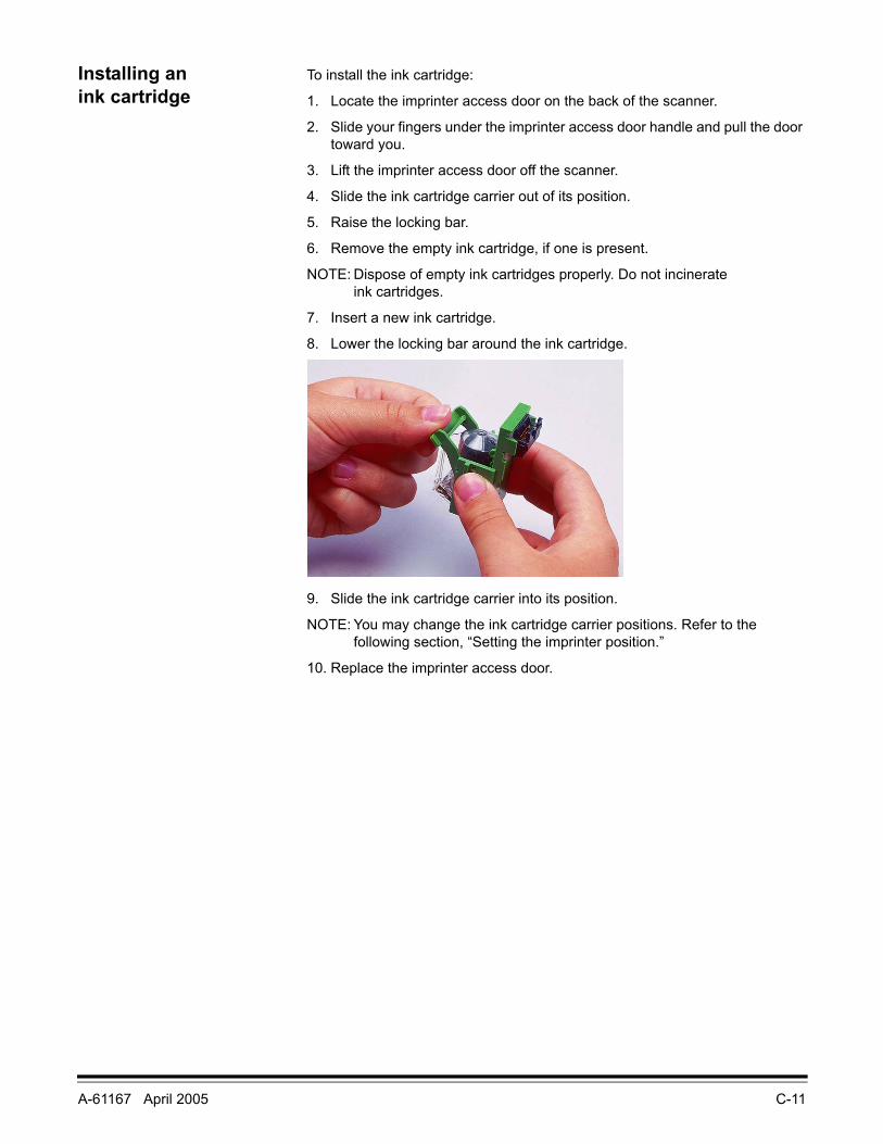
7. Insert a new ink cartridge.
8. Lower the locking bar around the ink cartridge.
9. Slide the ink cartridge carrier into its position.
NOTE: You may change the ink cartridge carrier positions. Refer to the following section, “Setting the imprinter position.”
10. Replace the imprinter access door.
C-12 A-61167 April 2005
Setting the imprinter position
There are 14 possible positions for the imprinter. Make sure that the imprinter is in the correct position for your documents.
1. Locate the imprinter access door on the back of the scanner.
2. Slide your fingers under the imprinter access door handle and pull the door toward you.
3. Lift the imprinter access door off the scanner.
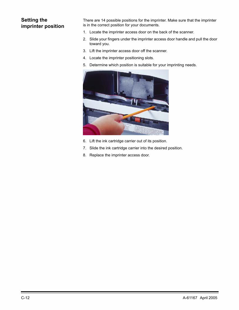
4. Locate the imprinter positioning slots.
5. Determine which position is suitable for your imprinting needs.
6. Lift the ink cartridge carrier out of its position.
7. Slide the ink cartridge carrier into the desired position.
8. Replace the imprinter access door.

A-61167 April 2005 C-13
Imprinter maintenance The ink cartridges, ink blotter strips, and ink cartridge carrier used in the imprinter will need replacing occasionally.
Imprinting problems If you are having problems imprinting on scanned documents:
• Verify that the ink cartridge is not empty. The ink bladder inside the cartridge is flat when it is empty.
• Make sure that the ink cartridge is properly installed in the imprinter.
• Make sure that the ink cartridge is located in the correct position for imprinting.
• Make sure that the ink cartridge carrier is properly seated in its positioning slot.
• Verify that all imprinter connectors are securely fastened and that the imprinter cables are not folded or creased.
Expected life of imprinter components
• Imprinter ink cartridge: approximately 750,000 non-bold characters per cartridge
• Ink blotter strips: replace as necessary when soiled
• Ink cartridge carrier: approximately 500,000 pages
When the imprinter is not in use
When the imprinter is not being used, place the ink cartridge on its side so that ink does not drip down on the blotter strips.
Replacing an ink cartridge Refer to “Installing an ink cartridge” in this chapter for information about replacing an empty ink cartridge.
Purchase ink cartridges from an office supply retailer near you.
C-14 A-61167 April 2005
Replacing the ink blotter strips
Two ink blotter strips in the scanner collect ink overflow. These strips should be replaced as necessary. To order additional ink blotter strips, refer to Appendix B, Supplies and Accessories.
NOTE: Improperly aligned blotter strips may cause paper jams.
1. Power down the scanner.
2. Disconnect the power cord.
3. Remove any documents from the feeder area.
4. Lift up the scanner door release to unlatch the scanner door.
5. Pull up to open the scanner door.
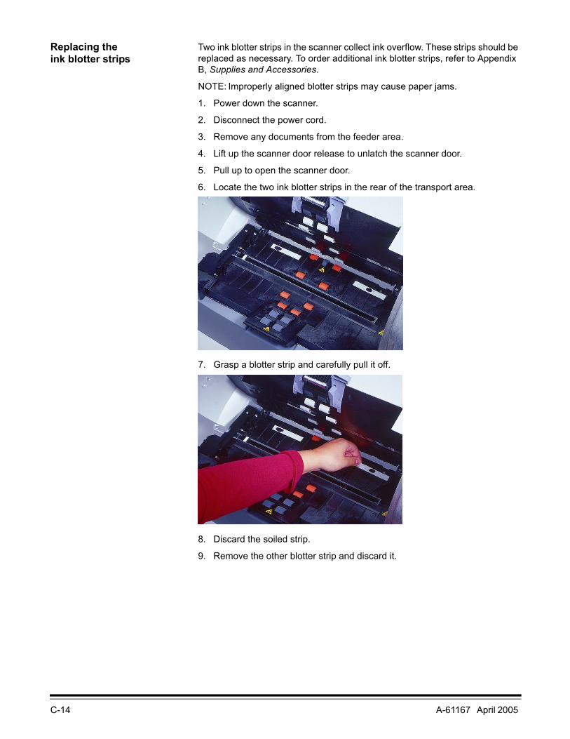
6. Locate the two ink blotter strips in the rear of the transport area.
7. Grasp a blotter strip and carefully pull it off.
8. Discard the soiled strip.
9. Remove the other blotter strip and discard it.

A-61167 April 2005 C-15
10. Remove the backing from a new blotter strip.
11. Align the blotter strip in one of the channels.
12. Press the adhesive side of the blotter strip down firmly into the channel.
13. Repeat Steps 10-12 for the other strip.
14. Lower the scanner door and press it firmly until it snaps into place.
Replacing the ink cartridge carrier
To order ink cartridge carriers, refer to Appendix B, Supplies and Accessories.
1. Locate the imprinter access door on the back of the scanner.
2. Slide your fingers under the imprinter access door handle and pull the door toward you.
3. Lift the imprinter access door off the scanner.
4. Slide the ink cartridge carrier out of its position.
5. Raise the locking bar.
6. Remove the ink cartridge, if one is present.
7. Squeeze the metal strips on the connector and pull the connector away from the ink cartridge carrier.
8. Push the connector firmly into a new ink cartridge carrier.
9. Replace the ink cartridge.
10. Lower the locking bar around the ink cartridge.
11. Slide the ink cartridge carrier back into its position.
12. Replace the imprinter access door.
C-16 A-61167 April 2005
Imprinting overview Many applications with capture needs up to 10,000 pages per day, particularly in the finance, insurance, and public administration industries, require an imprinter. Furthermore, forms processing applications in all areas can benefit from the use of an imprinter.
The Kodak i200 Series Imprinter is unique in that the document print string can be configured to include both literal (static) information (i.e., information that stays the same for each document, such as batch name, scan station, or operator) and dynamic information (i.e., information that may change for each page scanned, such as sequential document number). Software controls static fields; any information that the software allows you to enter can be sent to the imprinter. The imprinter can be manually placed in 14 horizontal positions.
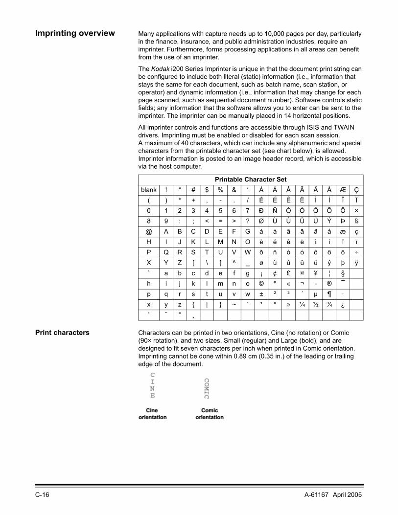
All imprinter controls and functions are accessible through ISIS and TWAIN drivers. Imprinting must be enabled or disabled for each scan session. A maximum of 40 characters, which can include any alphanumeric and special characters from the printable character set (see chart below), is allowed. Imprinter information is posted to an image header record, which is accessible via the host computer.
Print characters Characters can be printed in two orientations, Cine (no rotation) or Comic (90× rotation), and two sizes, Small (regular) and Large (bold), and are designed to fit seven characters per inch when printed in Comic orientation. Imprinting cannot be done within 0.89 cm (0.35 in.) of the leading or trailing edge of the document.
Printable Character Setblank ! “ # $ % & ‘ À Á Â Ã Ä Å Æ Ç
( ) * + , - . / È É Ê Ë Ì Í Î Ï0 1 2 3 4 5 6 7 Ð Ñ Ò Ó Ô Õ Ö ×8 9 : ; < = > ? Ø Ù Ú Û Ü Ý Þ ß@ A B C D E F G à á â ã ä å æ çH I J K L M N O è é ê ë ì í î ïP Q R S T U V W ð ñ ò ó ô õ ö ÷X Y Z [ \ ] ^ _ ø ù ú û ü ý þ ÿ` a b c d e f g ¡ ¢ £ ¤ ¥ ¦ §h i j k l m n o © ª « ¬ - ® ¯p q r s t u v w ± ² ³ ´ µ ¶ ·x y z { | } ~ ‘ ¹ º » ¼ ½ ¾ ¿’ ¨ ° ¸

A-61167 April 2005 C-17
The resolution of the character fonts is 96 dpi across the width of the scanner. However, the font resolution varies with the direction that the paper is fed into the scanner. This variable allows the creation of an easy-to-read character string. The approximate resolution of the printed output is shown below.
Changes to the print string, other than automatic, sequential number advances, require a host command to restart the imprinter. You must initiate a change between documents or batches. Changes cannot be done automatically or between documents “on the fly.”
NOTE: The minimum document width for using the imprinter is 14 cm (5.5 in.).
Imprinter specifications
Maximum lines 1
Print locations (horizontal) 14, manually set
Print locations (vertical) Set by host
Print orientation Cine or Comic
Font size Large or Small
Ink cartridge HP51604A or compatible
Print side Rear (post-scan)
Minimum imprinting distance 0.89 cm (0.35 in.)from document edge
Static fields available User-specified via host
Dynamic fields available Up to nine-digit sequential document number, date, four-digit time
Languages supported Any phonetic language (for example, Danish, Dutch, English, Finnish, French, German, Italian, Norwegian, Portuguese, Spanish, Swedish)
Resolution (dpi)Small Large
Cine 85 dpi 63 dpiComic 115 dpi 85dpi
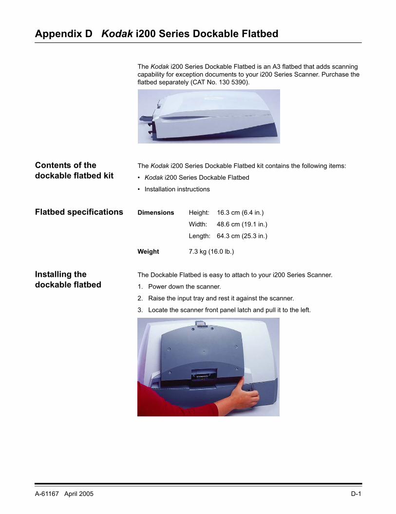
A-61167 April 2005 D-1
Appendix D Kodak i200 Series Dockable Flatbed
The Kodak i200 Series Dockable Flatbed is an A3 flatbed that adds scanning capability for exception documents to your i200 Series Scanner. Purchase the flatbed separately (CAT No. 130 5390).
Contents of the dockable flatbed kit
The Kodak i200 Series Dockable Flatbed kit contains the following items:
• Kodak i200 Series Dockable Flatbed
• Installation instructions
Flatbed specifications Dimensions Height: 16.3 cm (6.4 in.)
Width: 48.6 cm (19.1 in.)
Length: 64.3 cm (25.3 in.)
Weight 7.3 kg (16.0 lb.)
Installing the dockable flatbed
The Dockable Flatbed is easy to attach to your i200 Series Scanner.
1. Power down the scanner.
2. Raise the input tray and rest it against the scanner.
3. Locate the scanner front panel latch and pull it to the left.
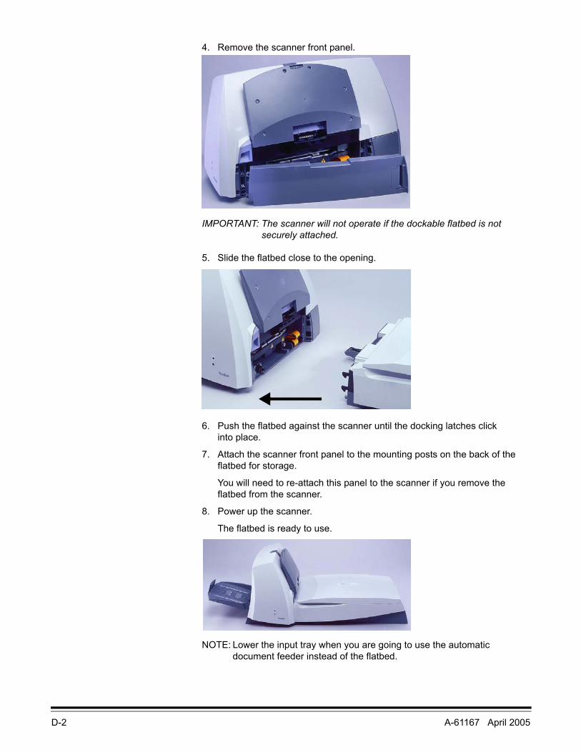
D-2 A-61167 April 2005
4. Remove the scanner front panel.
IMPORTANT: The scanner will not operate if the dockable flatbed is not securely attached.
5. Slide the flatbed close to the opening.
6. Push the flatbed against the scanner until the docking latches click into place.
7. Attach the scanner front panel to the mounting posts on the back of the flatbed for storage.
You will need to re-attach this panel to the scanner if you remove the flatbed from the scanner.
8. Power up the scanner.
The flatbed is ready to use.
NOTE: Lower the input tray when you are going to use the automatic document feeder instead of the flatbed.
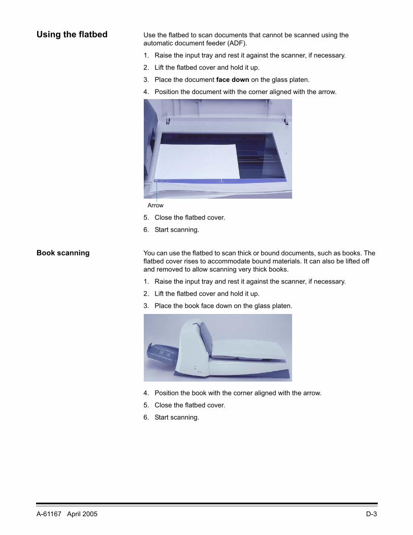
A-61167 April 2005 D-3
Using the flatbed Use the flatbed to scan documents that cannot be scanned using the automatic document feeder (ADF).
1. Raise the input tray and rest it against the scanner, if necessary.
2. Lift the flatbed cover and hold it up.
3. Place the document face down on the glass platen.
4. Position the document with the corner aligned with the arrow.
5. Close the flatbed cover.
6. Start scanning.
Book scanning You can use the flatbed to scan thick or bound documents, such as books. The flatbed cover rises to accommodate bound materials. It can also be lifted off and removed to allow scanning very thick books.
1. Raise the input tray and rest it against the scanner, if necessary.
2. Lift the flatbed cover and hold it up.
3. Place the book face down on the glass platen.
4. Position the book with the corner aligned with the arrow.
5. Close the flatbed cover.
6. Start scanning.
Arrow
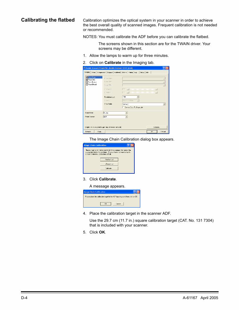
D-4 A-61167 April 2005
Calibrating the flatbed Calibration optimizes the optical system in your scanner in order to achieve the best overall quality of scanned images. Frequent calibration is not needed or recommended.
NOTES: You must calibrate the ADF before you can calibrate the flatbed.
The screens shown in this section are for the TWAIN driver. Your screens may be different.
1. Allow the lamps to warm up for three minutes.
2. Click on Calibrate in the Imaging tab.
The Image Chain Calibration dialog box appears.
3. Click Calibrate.
A message appears.
4. Place the calibration target in the scanner ADF.
Use the 29.7 cm (11.7 in.) square calibration target (CAT. No. 131 7304) that is included with your scanner.
5. Click OK.
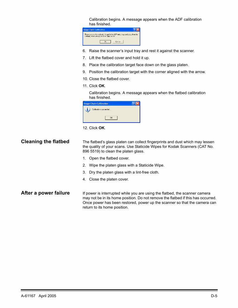
A-61167 April 2005 D-5
Calibration begins. A message appears when the ADF calibration has finished.
6. Raise the scanner’s input tray and rest it against the scanner.
7. Lift the flatbed cover and hold it up.
8. Place the calibration target face down on the glass platen.
9. Position the calibration target with the corner aligned with the arrow.
10. Close the flatbed cover.
11. Click OK.
Calibration begins. A message appears when the flatbed calibration has finished.
12. Click OK.
Cleaning the flatbed The flatbed’s glass platen can collect fingerprints and dust which may lessen the quality of your scans. Use Staticide Wipes for Kodak Scanners (CAT No. 896 5519) to clean the platen glass.
1. Open the flatbed cover.
2. Wipe the platen glass with a Staticide Wipe.
3. Dry the platen glass with a lint-free cloth.
4. Close the platen cover.
After a power failure If power is interrupted while you are using the flatbed, the scanner camera may not be in its home position. Do not remove the flatbed if this has occurred. Once power has been restored, power up the scanner so that the camera can return to its home position.
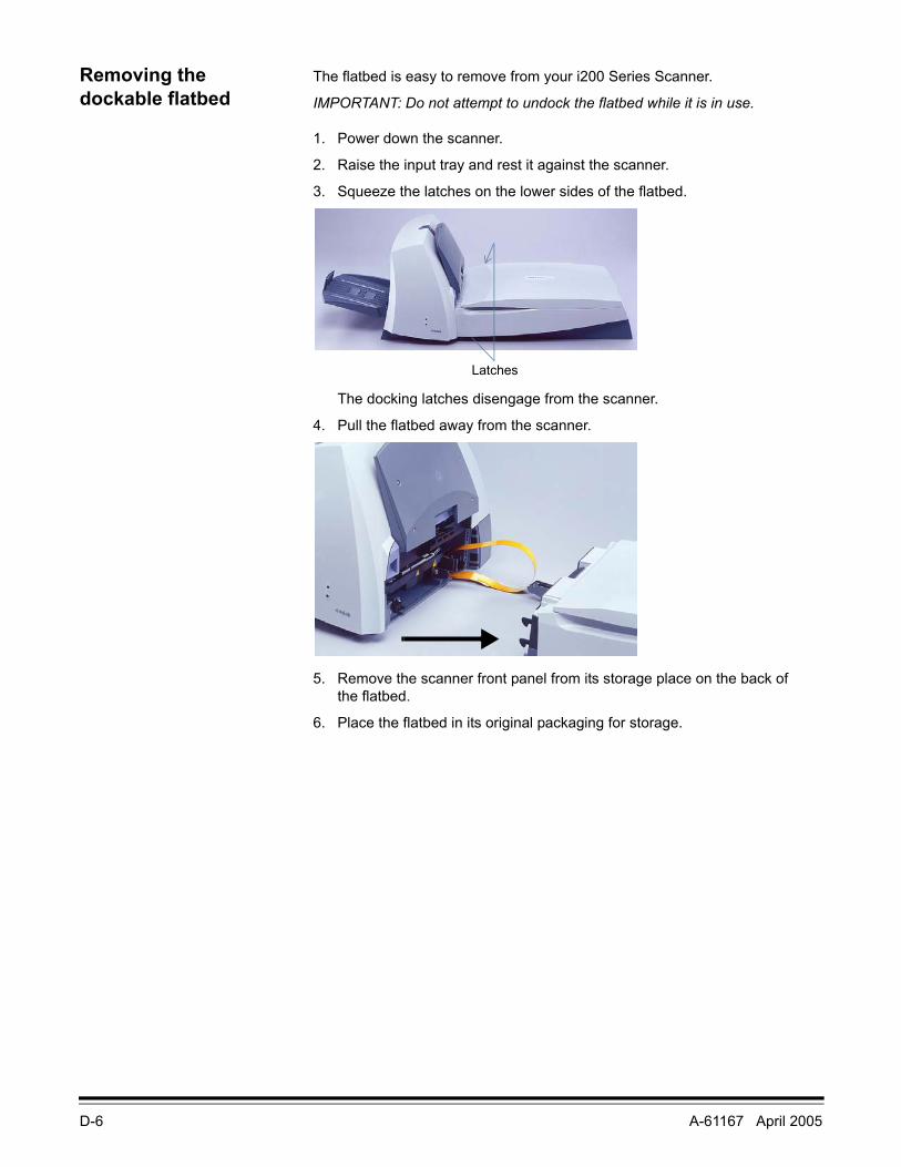
D-6 A-61167 April 2005
Removing the dockable flatbed
The flatbed is easy to remove from your i200 Series Scanner.
IMPORTANT: Do not attempt to undock the flatbed while it is in use.
1. Power down the scanner.
2. Raise the input tray and rest it against the scanner.
3. Squeeze the latches on the lower sides of the flatbed.
The docking latches disengage from the scanner.
4. Pull the flatbed away from the scanner.
5. Remove the scanner front panel from its storage place on the back of the flatbed.
6. Place the flatbed in its original packaging for storage.
Latches
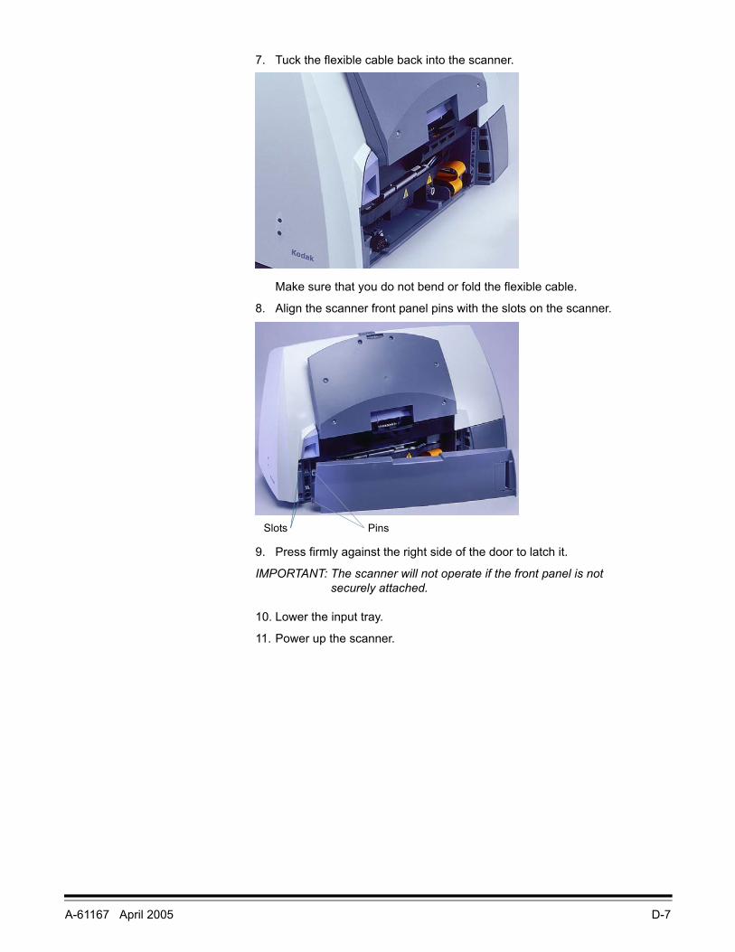
A-61167 April 2005 D-7
7. Tuck the flexible cable back into the scanner.
Make sure that you do not bend or fold the flexible cable.
8. Align the scanner front panel pins with the slots on the scanner.
9. Press firmly against the right side of the door to latch it.
IMPORTANT: The scanner will not operate if the front panel is not securely attached.
10. Lower the input tray.
11. Power up the scanner.
PinsSlots
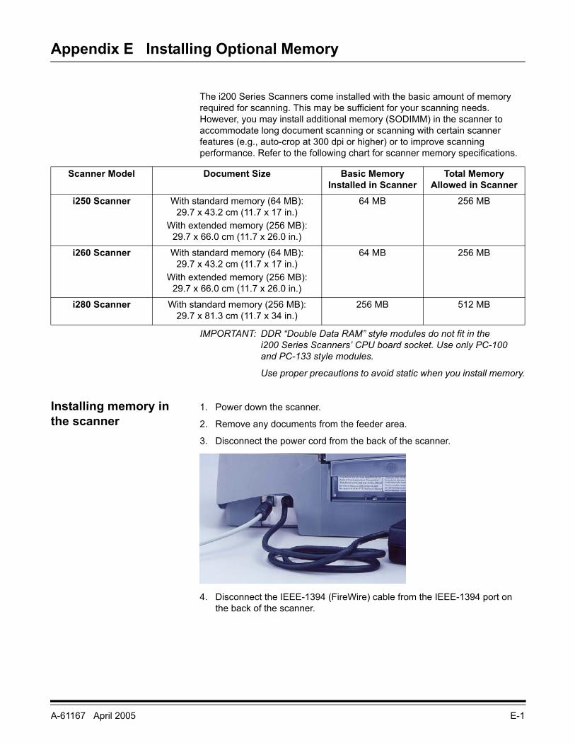
A-61167 April 2005 E-1
Appendix E Installing Optional Memory
The i200 Series Scanners come installed with the basic amount of memory required for scanning. This may be sufficient for your scanning needs. However, you may install additional memory (SODIMM) in the scanner to accommodate long document scanning or scanning with certain scanner features (e.g., auto-crop at 300 dpi or higher) or to improve scanning performance. Refer to the following chart for scanner memory specifications.
IMPORTANT: DDR “Double Data RAM” style modules do not fit in the i200 Series Scanners’ CPU board socket. Use only PC-100 and PC-133 style modules.
Use proper precautions to avoid static when you install memory.
Installing memory in the scanner
1. Power down the scanner.
2. Remove any documents from the feeder area.
3. Disconnect the power cord from the back of the scanner.
4. Disconnect the IEEE-1394 (FireWire) cable from the IEEE-1394 port on the back of the scanner.
Scanner Model Document Size Basic Memory Installed in Scanner
Total Memory Allowed in Scanner
i250 Scanner With standard memory (64 MB): 29.7 x 43.2 cm (11.7 x 17 in.)
With extended memory (256 MB): 29.7 x 66.0 cm (11.7 x 26.0 in.)
64 MB 256 MB
i260 Scanner With standard memory (64 MB): 29.7 x 43.2 cm (11.7 x 17 in.)
With extended memory (256 MB): 29.7 x 66.0 cm (11.7 x 26.0 in.)
64 MB 256 MB
i280 Scanner With standard memory (256 MB): 29.7 x 81.3 cm (11.7 x 34 in.)
256 MB 512 MB
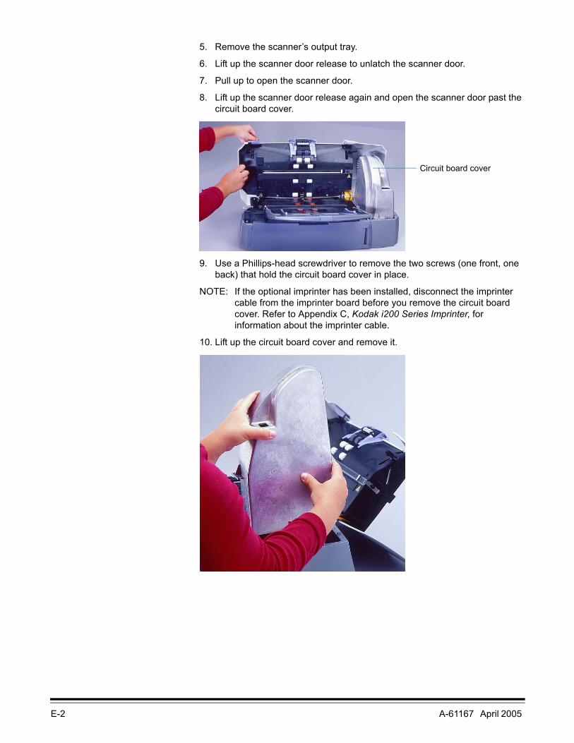
E-2 A-61167 April 2005
5. Remove the scanner’s output tray.
6. Lift up the scanner door release to unlatch the scanner door.
7. Pull up to open the scanner door.
8. Lift up the scanner door release again and open the scanner door past the circuit board cover.
9. Use a Phillips-head screwdriver to remove the two screws (one front, one back) that hold the circuit board cover in place.
NOTE: If the optional imprinter has been installed, disconnect the imprinter cable from the imprinter board before you remove the circuit board cover. Refer to Appendix C, Kodak i200 Series Imprinter, for information about the imprinter cable.
10. Lift up the circuit board cover and remove it.
Circuit board cover
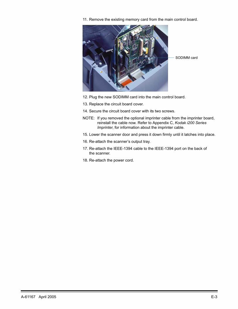
A-61167 April 2005 E-3
11. Remove the existing memory card from the main control board.
12. Plug the new SODIMM card into the main control board.
13. Replace the circuit board cover.
14. Secure the circuit board cover with its two screws.
NOTE: If you removed the optional imprinter cable from the imprinter board, reinstall the cable now. Refer to Appendix C, Kodak i200 Series Imprinter, for information about the imprinter cable.
15. Lower the scanner door and press it down firmly until it latches into place.
16. Re-attach the scanner’s output tray.
17. Re-attach the IEEE-1394 cable to the IEEE-1394 port on the back of the scanner.
18. Re-attach the power cord.
SODIMM card

EASTMAN KODAK COMPANYDocument ImagingRochester, New York 14650
www.kodak.com/go/docimaging
Kodak and Digital Science are trademarks of Eastman Kodak Company.
A-61167 4/2005Cat. No. 850 7543©Eastman Kodak Company, 2004