ES930 Multi-I/O Module EN - etas.com · PDF fileES930 Multi-I/O Module At a Glance ... Modules...
4
ES930 Multi-I/O Module At a Glance Multi-I/O module for prototyping, testing and calibration High performance with numerous functions 16 different input channels: thermo, analog, digital 4 sensor power supplies 10 different output channels 6 half-bridges with current measurement, controlled by digital outputs The ES930 Multi-I/O Module is a power- ful, flexible I/O all-rounder with an excellent price/performance ratio. The ES930 Multi-I/O Module is a compact, rugged, versatile and powerful module with several digital and analog input and output channels for signal recording and output. It can be used for rapid prototyp- ing, testing and calibration. The module also extends the functionality of the ES910 Prototyping and Interface Module, which makes it suitable for con- trolling and analyzing sensors and actua- tors directly from within a given function model, including ASCET, Simulink ® , and C code models. Interconnecting the Prototyping and Interface Modules ES910/ ES920 with the ES930 Multi-I/O Module opens up a broad spectrum of options for systems requiring access to ETK, FETK, XETK, FlexRay, CAN, and LIN, along with simultaneous access to all current analog and digital I/O-signals. The ETAS INTECRIO and ETAS ASCET-RP rapid prototyping software and the widely used ETAS INCA calibration tool support all functions of the ES930 Multi-I/O Module. Altogether, the ES930 Multi-I/O Module features four thermal inputs, eight analog and four digital inputs. On the output side, the module provides four analog and six digital outputs, six half-bridge-switches with current measurement, as well as four sensor power supplies. All channel set- tings can be configured for each channel. The number of channels can be extended by connecting several ES930 Multi-I/O Modules in an ETAS Ethernet daisy chain configuration. Additional signal types, such as lambda measurements, can be added effortlessly by means of the ETAS
Transcript of ES930 Multi-I/O Module EN - etas.com · PDF fileES930 Multi-I/O Module At a Glance ... Modules...

ES930 Multi-I/O Module
At a Glance
Multi-I/O module for
prototyping, testing and
calibration
High performance with
numerous functions
16 different input channels:
thermo, analog, digital
4 sensor power supplies
10 different output
channels
6 half-bridges with current
measurement, controlled by
digital outputs
The ES930 Multi-I/O Module is a power-
ful, flexible I/O all-rounder with
an excellent price/performance ratio.
The ES930 Multi-I/O Module is a compact,
rugged, versatile and powerful module
with several digital and analog input and
output channels for signal recording and
output. It can be used for rapid prototyp-
ing, testing and calibration.
The module also extends the functionality
of the ES910 Prototyping and Interface
Module, which makes it suitable for con-
trolling and analyzing sensors and actua-
tors directly from within a given function
model, including ASCET, Simulink®, and
C code models. Interconnecting the
Prototyping and Interface Modules ES910/
ES920 with the ES930 Multi-I/O Module
opens up a broad spectrum of options for
systems requiring access to ETK, FETK,
XETK, FlexRay, CAN, and LIN, along with
simultaneous access to all current analog
and digital I/O-signals.
The ETAS INTECRIO and ETAS ASCET-RP
rapid prototyping software and the widely
used ETAS INCA calibration tool support
all functions of the ES930 Multi-I/O Module.
Altogether, the ES930 Multi-I/O Module
features four thermal inputs, eight analog
and four digital inputs. On the output
side, the module provides four analog and
six digital outputs, six half-bridge-switches
with current measurement, as well as four
sensor power supplies. All channel set-
tings can be configured for each channel.
The number of channels can be extended
by connecting several ES930 Multi-I/O
Modules in an ETAS Ethernet daisy chain
configuration. Additional signal types,
such as lambda measurements, can be
added effortlessly by means of the ETAS

ES4xx/ES63x measurement modules. The
Ethernet interface allows a performance
connection to the function model which is
created on the ES910 Prototyping and In-
terface Module.
The frequently required half-bridges, e.g.,
for valve or electric motor applications, are
integrated in the module, which dispenses
with external signal conditioning. A full-
bridge (H-bridge) to control electric mo-
tors can be realized with two synchro-
nized half-bridges of the module. To drive
brushless direct-current motors (BLDC) it
is possible to operate three half-bridges
with a three-phase center aligned PWM*
signal.
A current sense in the output path of the
half-bridge sends the current back to the
function model as a direct result of the
control variable.
The inputs can be operated either in a
predefined, equidistant time raster or in
an event triggered mode. In the latter
case, a measured value is transmitted only
when a specific event has occurred on a
digital input. Such an event, e.g., a falling
signal edge, triggers the synchronous
measurement of all inputs coupled to this
event. In the rapid prototyping module,
these event-triggered input signals facili-
tate the synchronization of the model
sequencing to external events.
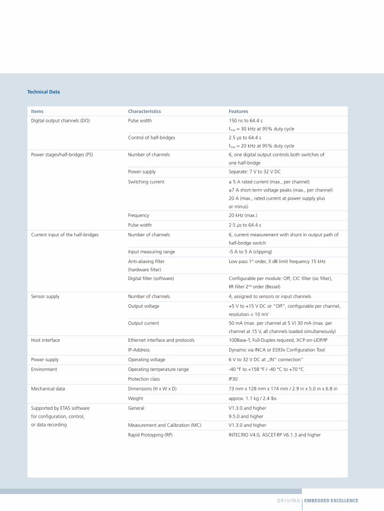
Technical Data
Items Characteristics Features
Thermo channels (TH) Number of channels 4, thermocouples type K
Measuring range -200 °C to +1372 °C / 73 °F to 2501 °F
Analog input channels (AI) Number of channels 8
Measuring range, resolution ±1 V, ±10 V, ±60 V for differential input voltages, 16 bit
Anti-aliasing filter
(hardware filter)
Low-pass, 2nd order (Bessel),
3 dB limit frequency 10 kHz
Digital low-pass filter Digital FIR low-pass 8th order (Butterworth)
with adjustable limit frequency, switched
Digital input channels (DI) Number of channels 4
Input voltage 0 V to 5 V, TTL-compatible
Counter width, resolution 32 bit, 15 ns
Functionality Active time, inactive time, counter, state;
event raster generation
Glitch filter 120 ns to 3000 ns or “Off”, resolution 15 ns
Timeout Configurable per channel: 0.1 s to 64.4 s or “Off”
Events 4 event sources per module can be configured differently
Event functionality Triggering a synchronous data acquisition on the ES930
module; triggering the model trigger in the ES910
Prototyping and Interface Module
Analog output channels (AO) Number of channels 4
Output voltage, resolution 0 V to +10 V, 14 bit
Output current ± 4 mA (max.)
Digital output channels (DO) Number of channels 6
Output voltage TTL-compatible
Counter width, resolution 32 bit, 15 ns
Function PWM Out, Pulse Out, Digital Out;
simultaneously control of the half-bridges (PS);
configurable synchronous channel groups
Technical Data
Items Characteristics Features
Digital output channels (DO) Pulse width 150 ns to 64.4 s
fmax = 30 kHz at 95% duty cycle
Control of half-bridges 2.5 μs to 64.4 s
fmax = 20 kHz at 95% duty cycle
Power stages/half-bridges (PS) Number of channels 6, one digital output controls both switches of
one half-bridge
Power supply Separate: 7 V to 32 V DC
Switching current ± 5 A rated current (max., per channel)
±7 A short-term voltage peaks (max., per channel)
20 A (max., rated current at power supply plus
or minus)
Frequency 20 kHz (max.)
Pulse width 2.5 μs to 64.4 s
Current input of the half-bridges Number of channels 6, current measurement with shunt in output path of
half-bridge switch
Input measuring range -5 A to 5 A (clipping)
Anti-aliasing filter
(hardware filter)
Low pass 1st order, 3 dB limit frequency 15 kHz
Digital filter (software) Configurable per module: Off, CIC filter (sic filter),
IIR filter 2nd order (Bessel)
Sensor supply Number of channels 4, assigned to sensors or input channels
Output voltage +5 V to +15 V DC or “Off”, configurable per channel,
resolution < 10 mV
Output current 50 mA (max. per channel at 5 V) 30 mA (max. per
channel at 15 V, all channels loaded simultaneously)
Host interface Ethernet interface and protocols 100Base-T, Full-Duplex required, XCP-on-UDP/IP
IP-Address Dynamic via INCA or ES93x Configuration Tool
Power supply Operating voltage 6 V to 32 V DC at „IN“ connection“
Environment Operating temperature range -40 °F to +158 °F / -40 °C to +70 °C
Protection class IP30
Mechanical data Dimensions (H x W x D) 73 mm x 128 mm x 174 mm / 2.9 in x 5.0 in x 6.8 in
Weight approx. 1.1 kg / 2.4 lbs
Supported by ETAS software
for configuration, control,
or data recording
General V1.3.0 and higher
9.5.0 and higher
Measurement and Calibration (MC) V1.3.0 and higher
Rapid Protoyping (RP) INTECRIO V4.0, ASCET-RP V6.1.3 and higher

ETA
S-PG
A/M
KC2_
AKO
/05
_201
6
Figure 1: The ES930 Multi-I/O Module in connection with the other ETAS tools for efficient prototyping.
Figure 2: The ES930 Multi-I/O Module works with other ETAS tools for measurement and calibration.
Multi I/O-ModuleES930 Ethernet Measurement Modules
ES4xx
Lambda MeasurementModule
ES63x
Drive RecorderES720
ExperimentEnvironment
INCA + EIP
(X)ETK CAN, LINFlexRay
ECU
16Inputs
14 Outputs
6 Half-Bridges
Voltage,Temperature,Counter,...
Lambda
Rapid Prototyping-System
ES910, ES920, ES921
Integration andConfiguration of
HW and SWINTECRIO, ASCET-RP
CodeASCET,
Simulink®, orC-Code
A1
B
C
Real components, e.g. Vehicle, Testbench, Motor
Real components, e.g. Vehicle, Testbench, Motor
A2B
C
Interface Module ES59x
Multi I/O-ModuleES930 Ethernet Measurement Modules
ES4xx
Lambda MeasurementModule
ES63x
Drive RecorderES720
ExperimentEnvironment
INCA + EIP
(X)ETK CAN, LINFlexRay
ECU
16Inputs
14 Outputs
6 Half-Bridges
Voltage,Temperature,Counter,...
Lambda
More information is available at www.etas.com/ES930.
ETAS Locations Worldwide
Germany
Stuttgart (Headquarter)
Brazil
São Bernardo do Campo
Canada
Kitchener
France
Saint-Ouen
India
Bangalore
Pune
Italy
Turin
Japan
Utsunomiya
Yokohama
Korea
Seongnam-si
P.R. China
Beijing
Changchun
Chongqing
Guangzhou
Shanghai
Wuhan
Sweden
Gothenburg
United Kingdom
Derby
York
USA
Ann Arbor
www.etas.com
1 PWM = Puls width modulation