es s T d ng - Sandvik Coromant · 2012-02-01 · A new generation of steel milling grades, very...
32
Best practice machining of wind power components Tool and method advances for efficient manufacturing
Transcript of es s T d ng - Sandvik Coromant · 2012-02-01 · A new generation of steel milling grades, very...
Best practice machining of wind power components
Tool and method
advances for efficient
manufacturing
48 19
282
Introduction
WIND POWER – EDITORIAL
Manufacturing parts for the wind-power industry is an opportunity area for many suppliers of machined components. The industry is growing, has a bright future and many parts are machining intensive. But as with all potential business areas, competitiveness also becomes a growth factor. Incorporating best practice with continuous improvements in manufac-turing makes one of the most important competitive differences.
There are three determining manufac-turing issues: quality, delivery and produc-tion costs. Many wind power components are machining intensive and as such dependent on the methods and means applied for metal cutting.
For example, how up to date are the milling operations and cutters involved? How long do shafts stay on the lathe? How efficient is the drilling of the large amounts of holes? How up to date is the machining of gear wheels? Is tool holding stability at an optimum to allow competi-tive cutting data for roughing and main-taining quality levels in finishing?
These issues and more are easily reviewed in the machine shop and can be readily transformed with direct improve-ments in manufacturing. This brochure aims at pointing out a number of devel-opments that provide best practice in machining most of the typical wind power components.
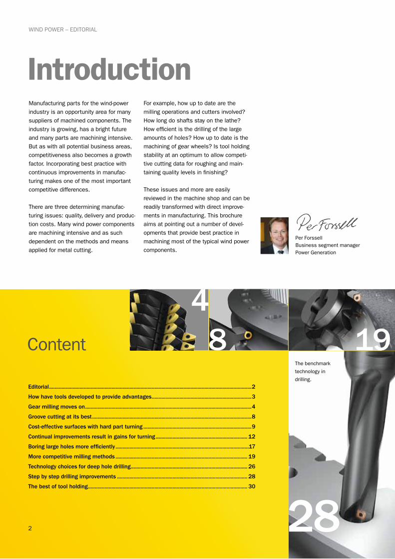
Editorial ..................................................................................................................................................2
How have tools developed to provide advantages ........................................................................3
Gear milling moves on ........................................................................................................................4
Groove cutting at its best ...................................................................................................................8
Cost-effective surfaces with hard part turning ..............................................................................9
Continual improvements result in gains for turning .................................................................. 12
Boring large holes more efficiently ................................................................................................17
More competitive milling methods ............................................................................................... 19
Technology choices for deep hole drilling .................................................................................... 26
Step by step drilling improvements .............................................................................................. 28
The best of tool holding ................................................................................................................... 30
ContentThe benchmark
technology in
drilling.
Per ForssellBusiness segment manager Power Generation
3
How have tools developed to provide advantages?
WIND POWER – TOOLS DEVELOPMENT
Components for wind power equipment are very varied in size, design, material and what needs to be machined. This means that they stand to gain broadly from the regular developments that are made to cutting tools and machining methods. Status quo for too many years, not taking advantage of available new concepts that lead to continuous improvements, means a measurable drop in competitiveness. Here are a couple of examples.
And what does it mean for manufacturing wind power components?
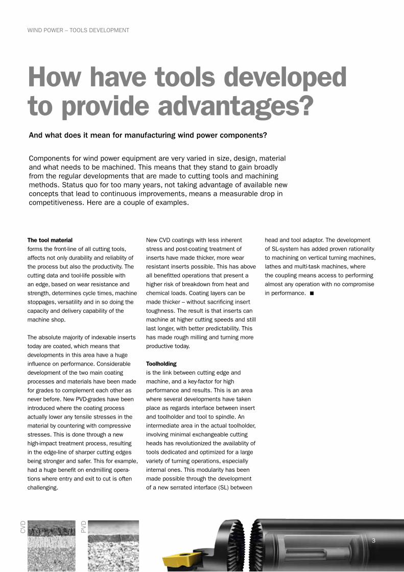
The tool materialforms the front-line of all cutting tools, affects not only durability and reliablity of the process but also the productivity. The cutting data and tool-life possible with an edge, based on wear resistance and strength, determines cycle times, machine stoppages, versatility and in so doing the capacity and delivery capability of the machine shop.
The absolute majority of indexable inserts today are coated, which means that developments in this area have a huge influence on performance. Considerable development of the two main coating processes and materials have been made for grades to complement each other as never before. New PVD-grades have been introduced where the coating process actually lower any tensile stresses in the material by countering with compressive stresses. This is done through a new high-impact treatment process, resulting in the edge-line of sharper cutting edges being stronger and safer. This for example, had a huge benefit on endmilling opera-tions where entry and exit to cut is often challenging.
New CVD coatings with less inherent stress and post-coating treatment of inserts have made thicker, more wear resistant inserts possible. This has above all benefitted operations that present a higher risk of breakdown from heat and chemical loads. Coating layers can be made thicker – without sacrificing insert toughness. The result is that inserts can machine at higher cutting speeds and still last longer, with better predictability. This has made rough milling and turning more productive today.
Toolholdingis the link between cutting edge and machine, and a key-factor for high performance and results. This is an area where several developments have taken place as regards interface between insert and toolholder and tool to spindle. An intermediate area in the actual toolholder, involving minimal exchangeable cutting heads has revolutionized the availablity of tools dedicated and optimized for a large variety of turning operations, especially internal ones. This modularity has been made possible through the development of a new serrated interface (SL) between
head and tool adaptor. The development of SL-system has added proven rationality to machining on vertical turning machines, lathes and multi-task machines, where the coupling means access to performing almost any operation with no compromise in performance. n
CVD PVD
4
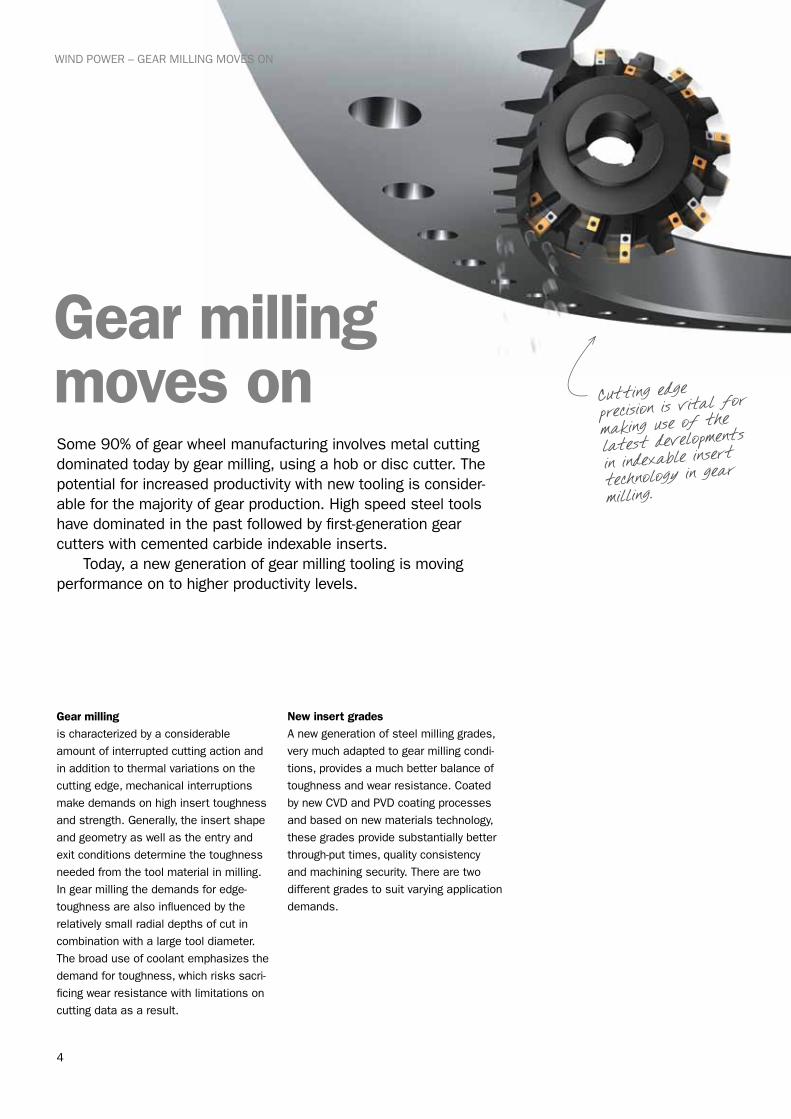
Gear milling moves onSome 90% of gear wheel manufacturing involves metal cutting dominated today by gear milling, using a hob or disc cutter. The potential for increased productivity with new tooling is consider-able for the majority of gear production. High speed steel tools have dominated in the past followed by first-generation gear cutters with cemented carbide indexable inserts. Today, a new generation of gear milling tooling is moving performance on to higher productivity levels.
Cutting edge precision is vital f
or
making use of the latest development
s
in indexable insert technology in gear milling.
WIND POWER – GEAR MILLING MOVES ON
Gear milling
is characterized by a considerable amount of interrupted cutting action and in addition to thermal variations on the cutting edge, mechanical interruptions make demands on high insert toughness and strength. Generally, the insert shape and geometry as well as the entry and exit conditions determine the toughness needed from the tool material in milling. In gear milling the demands for edge-toughness are also influenced by the relatively small radial depths of cut in combination with a large tool diameter. The broad use of coolant emphasizes the demand for toughness, which risks sacri-ficing wear resistance with limitations on cutting data as a result.
New insert gradesA new generation of steel milling grades, very much adapted to gear milling condi-tions, provides a much better balance of toughness and wear resistance. Coated by new CVD and PVD coating processes and based on new materials technology, these grades provide substantially better through-put times, quality consistency and machining security. There are two different grades to suit varying application demands.

5
WIND POWER – GEAR MILLING MOVES ON
Consistent gear quality is achieved with the unique, new
high-productivity hob!
GC4240 is a tough, steel-milling grade, CVD-coated for applications where cutting edge strength is needed to cope with more severe demands both as regards material and machining conditions. Gener-ally, this grade will solve most operations where a combination of high insert tough-ness in combination with resistance to heat and chemical breakdown is neces-sary. It will provide a reliable solution especially for medium to large diameter cutters when other insert grades will not give the insert strength for durability in an operation.
GC1030 is a PVD-coated steel milling grade for applications where a more posi-tive, sharper and tougher cutting-edge line is needed. Generally, this grade is ideal when radial depths of cut are smaller, vibration risks apparent, chip evacua-tion tricky and cutter entry and exit more demanding. This grade also functions better than GC4240 when coolants are applied for the gear milling.
Cutting edge precisionEdge geometry and edge preparation are important factors for achieving the best solution in gear milling and insert-manufacturing quality levels are a critical success factor. Establishing the right micro-geometry in the form of lands, chamfers and edge rounding decisively affect the strength characteristics of the cutting edge as well as tool life. Practi-cally, this has a direct influence on cutting data capability (productivity), production security and the predictabilility of quality consistency.
Gear milling cutters have a high number of relatively large inserts where the posi-tion of one cutting edge affects other edges as regards load during cut. If these loads vary too much, they nega-tively affect machining performance and capability to achieve quality. New insert manufacturing techniques, producing inserts to new geometry and higher accu-racy, play a critical role in achieving higher performance solutions. Sandvik Coromant gear milling cutters and inserts are made to new exacting standards to ensure optimum performance and results.
>>
6
WIND POWER – GEAR MILLING MOVES ON
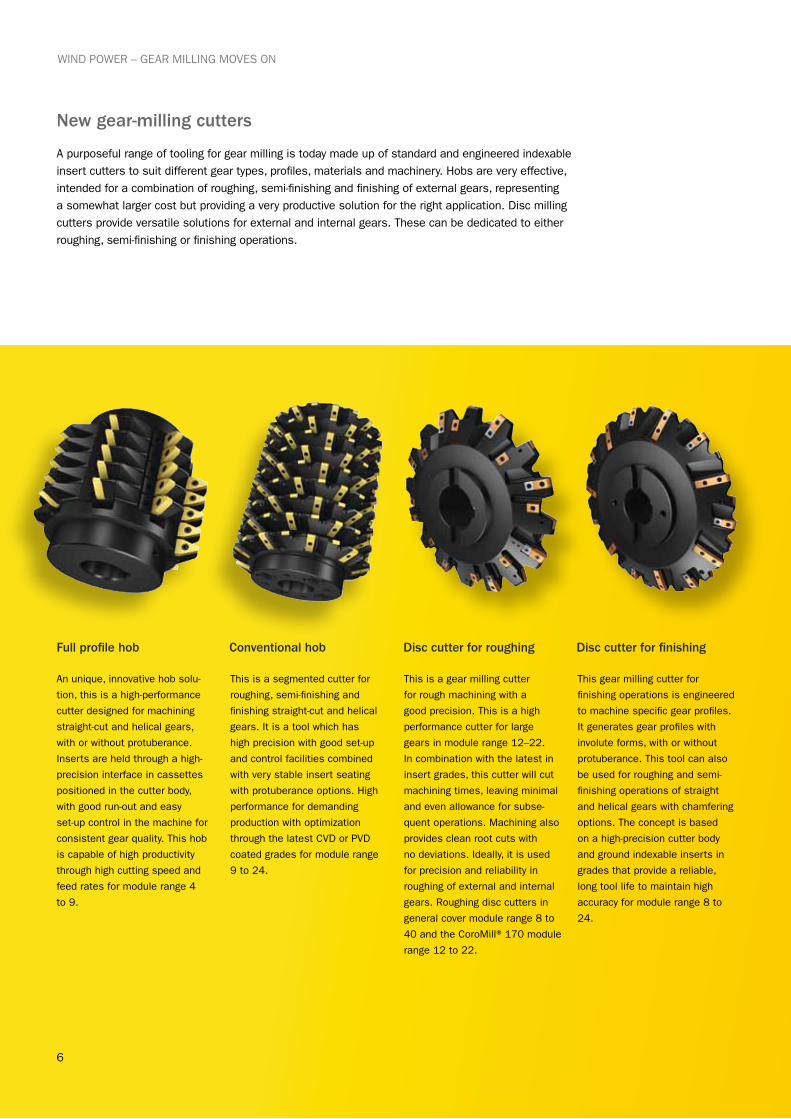
An unique, innovative hob solu-
tion, this is a high-performance
cutter designed for machining
straight-cut and helical gears,
with or without protuberance.
Inserts are held through a high-
precision interface in cassettes
positioned in the cutter body,
with good run-out and easy
set-up control in the machine for
consistent gear quality. This hob
is capable of high productivity
through high cutting speed and
feed rates for module range 4
to 9.
This is a segmented cutter for
roughing, semi-finishing and
finishing straight-cut and helical
gears. It is a tool which has
high precision with good set-up
and control facilities combined
with very stable insert seating
with protuberance options. High
performance for demanding
production with optimization
through the latest CVD or PVD
coated grades for module range
9 to 24.
This is a gear milling cutter
for rough machining with a
good precision. This is a high
performance cutter for large
gears in module range 12–22.
In combination with the latest in
insert grades, this cutter will cut
machining times, leaving minimal
and even allowance for subse-
quent operations. Machining also
provides clean root cuts with
no deviations. Ideally, it is used
for precision and reliability in
roughing of external and internal
gears. Roughing disc cutters in
general cover module range 8 to
40 and the CoroMill® 170 module
range 12 to 22.
This gear milling cutter for
finishing operations is engineered
to machine specific gear profiles.
It generates gear profiles with
involute forms, with or without
protuberance. This tool can also
be used for roughing and semi-
finishing operations of straight
and helical gears with chamfering
options. The concept is based
on a high-precision cutter body
and ground indexable inserts in
grades that provide a reliable,
long tool life to maintain high
accuracy for module range 8 to
24.
Full profile hob Disc cutter for roughingConventional hob Disc cutter for finishing
New gear-milling cutters
A purposeful range of tooling for gear milling is today made up of standard and engineered indexable insert cutters to suit different gear types, profiles, materials and machinery. Hobs are very effective, intended for a combination of roughing, semi-finishing and finishing of external gears, representing a somewhat larger cost but providing a very productive solution for the right application. Disc milling cutters provide versatile solutions for external and internal gears. These can be dedicated to either roughing, semi-finishing or finishing operations.
7
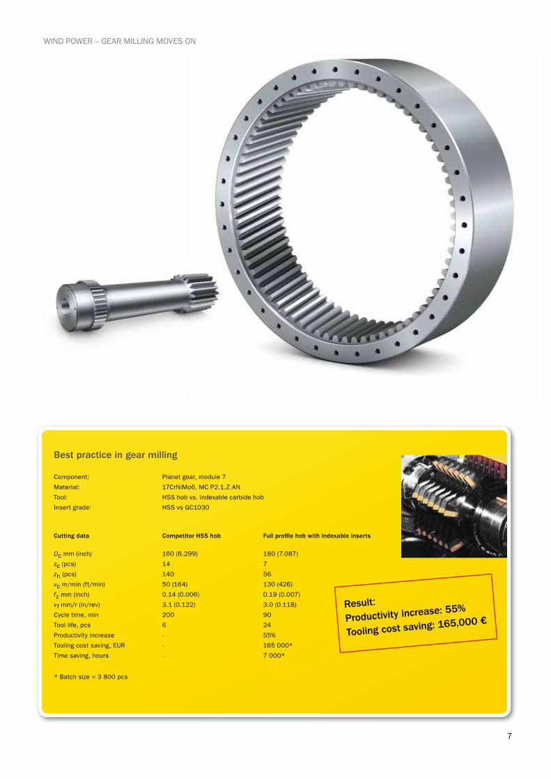
Component: Planet gear, module 7
Material: 17CrNiMo6, MC P2.1.Z.AN
Tool: HSS hob vs. indexable carbide hob
Insert grade: HSS vs GC1030
Cutting data Competitor HSS hob Full profile hob with indexable inserts
Dc mm (inch) 160 (6.299) 180 (7.087)
zc (pcs) 14 7
zn (pcs) 140 56
vc m/min (ft/min) 50 (164) 130 (426)
fz mm (inch) 0.14 (0.006) 0.19 (0.007)
vf mm/r (in/rev) 3.1 (0.122) 3.0 (0.118)
Cycle time, min 200 90
Tool life, pcs 6 24
Productivity increase - 55%
Tooling cost saving, EUR - 165 000*
Time saving, hours - 7 000*
Result:
Productivity increase: 55%
Tooling cost saving: 165,000 €
* Batch size = 3 800 pcs
Best practice in gear milling
WIND POWER – GEAR MILLING MOVES ON
8
WIND POWER – GROOVE CUTTING AT ITS BEST
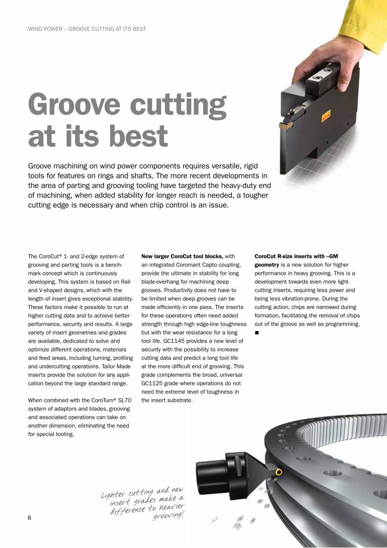
Groove cutting at its bestGroove machining on wind power components requires versatile, rigid tools for features on rings and shafts. The more recent developments in the area of parting and grooving tooling have targeted the heavy-duty end of machining, when added stability for longer reach is needed, a tougher cutting edge is necessary and when chip control is an issue.
Lighter cutting and new
insert grades make a
difference to heavier
grooving!
The CoroCut® 1- and 2-edge system of grooving and parting tools is a bench-mark concept which is continuously developing. This system is based on Rail and V-shaped designs, which with the length of insert gives exceptional stability. These factors make it possible to run at higher cutting data and to achieve better performance, security and results. A large variety of insert geometries and grades are available, dedicated to solve and optimize different operations, materials and feed areas, including turning, profiling and undercutting operations. Tailor Made inserts provide the solution for any appli-cation beyond the large standard range.
When combined with the CoroTurn® SL70 system of adaptors and blades, grooving and associated operations can take on another dimension, eliminating the need for special tooling.
New larger CoroCut tool blocks, with an integrated Coromant Capto coupling, provide the ultimate in stability for long blade-overhang for machining deep grooves. Productivity does not have to be limited when deep grooves can be made efficiently in one pass. The inserts for these operations often need added strength through high edge-line toughness but with the wear resistance for a long tool life. GC1145 provides a new level of security with the possibility to increase cutting data and predict a long tool life at the more difficult end of grooving. This grade complements the broad, universal GC1125 grade where operations do not need the extreme level of toughness in the insert substrate.
CoroCut R-size inserts with –GM geometry is a new solution for higher performance in heavy grooving. This is a development towards even more light-cutting inserts, requiring less power and being less vibration-prone. During the cutting action, chips are narrowed during formation, facilitating the removal of chips out of the groove as well as programming.
n
9
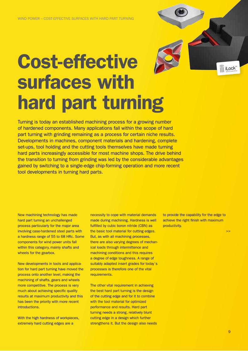
Cost-effective surfaces with hard part turning
WIND POWER – COST-EFFECTIVE SURFACES WITH HARD PART TURNING
Turning is today an established machining process for a growing number of hardened components. Many applications fall within the scope of hard part turning with grinding remaining as a process for certain niche results. Developments in machines, component materials and hardening, complete set-ups, tool holding and the cutting tools themselves have made turning hard parts increasingly accessible for most machine shops. The drive behind the transition to turning from grinding was led by the considerable advantages gained by switching to a single-edge chip-forming operation and more recent tool developments in turning hard parts.
New machining technology has made hard part turning an unchallenged process particularly for the major area involving case-hardened steel parts with a hardness range of 55 to 68 HRc. Some components for wind power units fall within this category, mainly shafts and wheels for the gearbox.
New developments in tools and applica-tion for hard part turning have moved the process onto another level, making the machining of shafts, gears and wheels more competitive. The process is very much about achieving specific quality results at maximum productivity and this has been the priority with more recent introductions.
With the high hardness of workpieces, extremely hard cutting edges are a
necessity to cope with material demands made during machining. Hardness is well fulfilled by cubic boron nitride (CBN) as the basic tool material for cutting edges. But, as with all machining processes, there are also varying degrees of mechan-ical loads through intermittence and machining conditions and this requires a degree of edge toughness. A range of suitably adapted insert grades for today`s processes is therefore one of the vital requirements.
The other vital requirement in achieving the best hard part turning is the design of the cutting edge and for it to combine with the tool material for optimized performance and results. Hard part turning needs a strong, relatively blunt cutting edge in a design which further strengthens it. But the design also needs
to provide the capability for the edge to achieve the right finish with maximum productivity.
>>

10
WIND POWER – COST-EFFECTIVE SURFACES WITH HARD PART TURNING
Grade CB7015 is the best choice for smooth cuts with high stability at the higher cutting speed end. This is an insert grade mainly for continuous turning with some capacity for lightly interrupted cuts, usually dedicated to light, optimized operations.
CB7025 is a better choice for when added toughness is needed and can thereby provide more versatility. Often a higher degree of interrupted cuts and some instability occur in mixed production with varying machinery and a lower level of cutting speeds. Some hard part turning operations need a more extreme level of edge toughness, such as for heavy interruptions or to cope with instability. This is fulfilled by grade CB7525, a complimentary large-tip solu-tion for providing maximum security for the cutting edge. This grade has an edge which can stand up to higher mechanical loads which usually entails shorter times in cut.
A key to maximize productivity in hard part turning is through the feed rate as the cutting speed is limited by the extreme heat generation at the edge. The design of the cutting edge is therefore crucial for combining finishing capability with productivity capability. Only a slight part of the edge is at any time in cut and this part has to leave a smooth surface at a high feed rate. New developments in this area have provided two cutting edge concepts.
The Xcel concept built on an approach led by small entering angle followed by a parallel land. The constant, comparatively small chip thickness means a slower, balanced wear development at a very high feed per revolution. This gives a close surface finish with high productivity. With a good stability set-up, productivity can often be raised considerably in relation to conventional nose-radius inserts. The Wiper technology has been applied to hard part turning with success and has a higher capability for depth of cut than Xcel. This concept builds on the combination and blending of several radii to replace a single nose radius. Produc-tivity levels are next to that of Xcel but with added versatility in turning and not needing as high stability demands. There are two Wiper edges: WH, the most versa-tile with lowest cutting forces and WG, offering the best finishing-to-productivity ratio with slightly higher cutting forces.
Hard part turning is
now optimized through
new combinations of
CBN-grades, cutting edge
designs and an exact,
stable insert location!
11
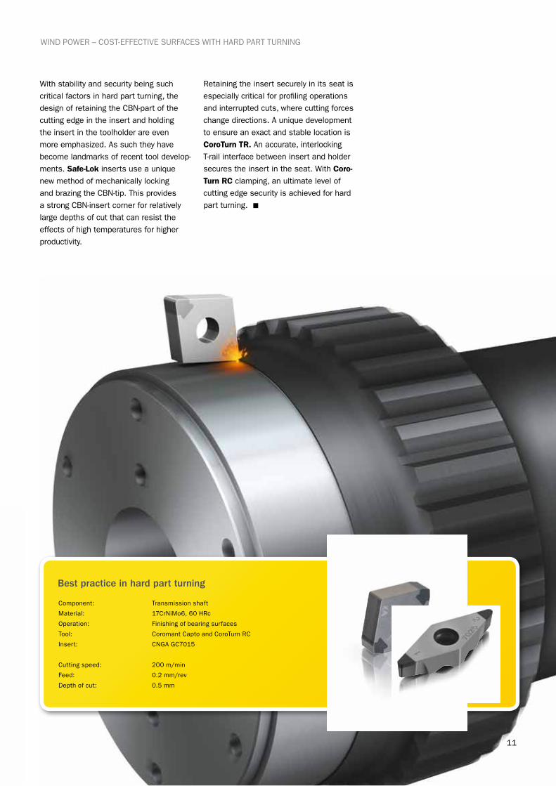
Component: Transmission shaft
Material: 17CrNiMo6, 60 HRc
Operation: Finishing of bearing surfaces
Tool: Coromant Capto and CoroTurn RC
Insert: CNGA GC7015
Cutting speed: 200 m/min
Feed: 0.2 mm/rev
Depth of cut: 0.5 mm
With stability and security being such critical factors in hard part turning, the design of retaining the CBN-part of the cutting edge in the insert and holding the insert in the toolholder are even more emphasized. As such they have become landmarks of recent tool develop-ments. Safe-Lok inserts use a unique new method of mechanically locking and brazing the CBN-tip. This provides a strong CBN-insert corner for relatively large depths of cut that can resist the effects of high temperatures for higher productivity.
Retaining the insert securely in its seat is especially critical for profiling operations and interrupted cuts, where cutting forces change directions. A unique development to ensure an exact and stable location is CoroTurn TR. An accurate, interlocking T-rail interface between insert and holder secures the insert in the seat. With Coro-Turn RC clamping, an ultimate level of cutting edge security is achieved for hard part turning. n
WIND POWER – COST-EFFECTIVE SURFACES WITH HARD PART TURNING
Best practice in hard part turning
12
Continual improvements result in gains for turning
WIND POWER – CONTINUAL IMPROVEMENTS RESULT IN GAINS FOR TURNING
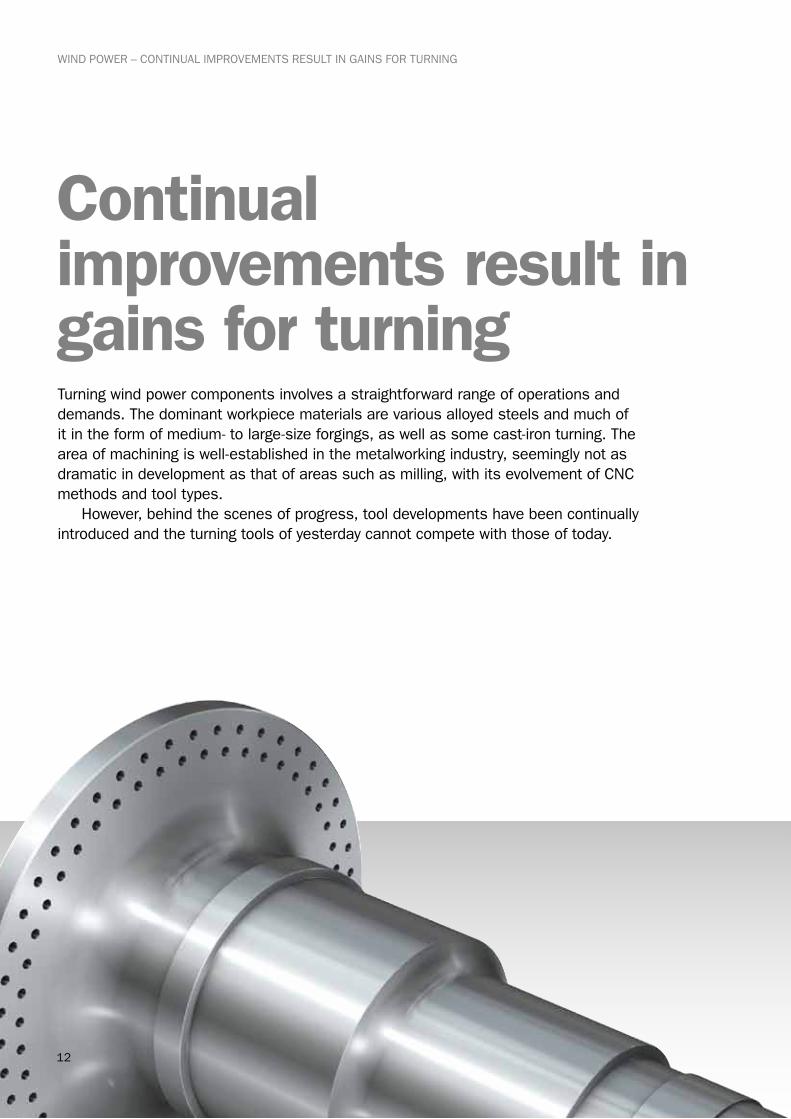
Turning wind power components involves a straightforward range of operations and demands. The dominant workpiece materials are various alloyed steels and much of it in the form of medium- to large-size forgings, as well as some cast-iron turning. The area of machining is well-established in the metalworking industry, seemingly not as dramatic in development as that of areas such as milling, with its evolvement of CNC methods and tool types. However, behind the scenes of progress, tool developments have been continually introduced and the turning tools of yesterday cannot compete with those of today.
13
WIND POWER – CONTINUAL IMPROVEMENTS RESULT IN GAINS FOR TURNING
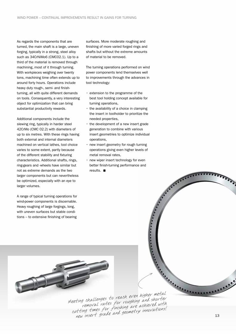
As regards the components that are turned, the main shaft is a large, uneven forging, typically in a strong, steel alloy such as 34CrNiMo6 (CMC02.1). Up to a third of the material is removed through machining, most of it through turning. With workpieces weighing over twenty tons, machining time often extends up to around forty hours. Operations include heavy duty rough-, semi- and finish-turning, all with quite different demands on tools. Consequently, a very interesting object for optimization that can bring substantial productivity rewards.
Additional components include the slewing ring, typically in harder steel 42CrMo (CMC 02.2) with diameters of up to six metres. With these rings having both external and internal diameters machined on vertical lathes, tool choice varies to some extent, partly because of the different stability and fixturing characteristics. Additional shafts, rings, ring-gears and -wheels have similar but not as extreme demands as the two larger components but can nevertheless be optimized, especially with an eye to larger volumes.
A range of typical turning operations for wind-power components is discernable. Heavy roughing of large forgings, long, with uneven surfaces but stable condi-tions – to extensive finishing of bearing
surfaces. More moderate roughing and finishing of more varied forged rings and shafts but without the extreme amounts of material to be removed.
The turning operations performed on wind power components lend themselves well to improvements through the advances in tool technology:
•extension to the programme of the best tool holding concept available for turning operations,
• the availability of a choice in clamping the insert in toolholder to prioritize the needed properties,
• the development of a new insert grade generation to combine with various insert geometries to optimize individual operations,
•new insert geometry for rough turning operations giving even higher levels of metal removal rates,
•new wiper insert technology for even better finish-turning performance and results. n
Meeting challenges to reach even higher
metal
removal rates for roughing and short
er
cutting times for finishing are achieve
d with
new insert grade and geometry innova
tions!

14
WIND POWER – CONTINUAL IMPROVEMENTS RESULT IN GAINS FOR TURNING
In turning, there is an established set of application parameters that make a lot of difference to the success of the opera-tion, be it heavy duty roughing or finishing. The main ones are, from machine to edge: tool holding, insert clamping, insert shape/entering angle and insert geometry/insert grade. All of these – and especially the way these parameters are combined – have undergone considerable development that affects performance, security and results.
Tool holding has improved through the standardization and availability of Coro-mant Capto, from small to large sizes. This strong, accurate, uncompromising coupling is as ideal for turning as it is for rotating tools. (See further under tool holding section).
Insert clamping now has two very secure methods, through the well-proven and refined strong T-Max P lever-clamping with maximized free flow of chips. And the CoroTurn RC very rigid clamping of inserts, especially for large components
and difficult conditions. This method of retaining the insert giving
extremely good stability, through both a lever and
top clamp, provides high operational secu-
rity, good functioning in varying roughing environments and easy, fast indexing and
maintenance.
For the indexable insert, the round RCM-type always provides the strongest cutting edge and as such a substantial basis for roughing wind power components. The large engagement of the edge means relatively large cutting forces, which often have to be countered with a positive cutting edge geometry. Here it is vital to combine one of the newly developed insert grades with the right balance of toughness and wear resistance to achieve the best results. The RCMT-type insert has proved itself successful when used in 20 or 25 mm IC sizes, providing high reliability for very productive machining when combined with a hard but tough grade like GC4215.
GC4215 is one of a range of new genera-tion grades, where high wear resistance has been combined with a strong edge-line. As such ideal for higher cutting data in rough-turning. This is a CVD-coated grade for withstanding high temperatures during long lasting cuts but tough enough to cope with uneven forged surfaces. This grade is a product of new coated insert technology in combining the optimum coating with a suitable insert substrate, advances in material science and newly evolved manufacturing processes. GC4215 is one of a modern family of the steel turning grades in the GC4000 series, covering the ISO P05 to P40 area with new levels of performance in combi-nation with the right insert geometry.
For wind power components, where forged alloy steel workpieces dominate,
coated inserts have been designed to stand up to abrasiveness and high temperatures. This means a harder insert with a good thermal barrier is usually the most suitable where a combination of two coating types is needed to partly prevent plastic deformation and crater wear of the edge but partly also to keep natural flank wear at an acceptable level for a long tool life. This is where the new four GC4000 insert grades provide a unique means to arrive at very competitive machining for rough and finish turning. n
Combining vital parameters in turning
15
WIND POWER – CONTINUAL IMPROVEMENTS RESULT IN GAINS FOR TURNING
The possibility to apply the best insert shape to maximize strength and to apply the most suitable entering angle is dependant on how extensive a turning tool programme is. It is also for the necessary cutting edge to be available in the right insert form and size to both optimize the operation but also provide good tool economy. The choice between round insert and square insert with a specific geometry and nose radius can be decisive in optimizing operations – in both roughing and finishing operations.
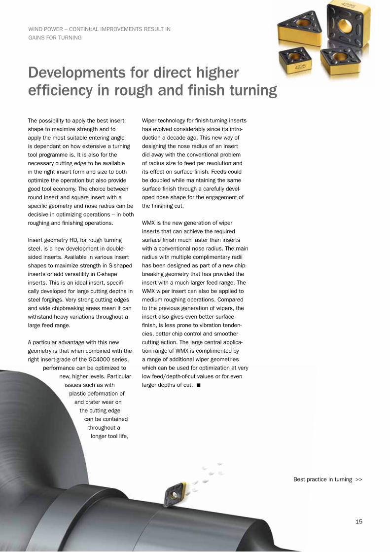
Insert geometry HD, for rough turning steel, is a new development in double-sided inserts. Available in various insert shapes to maximize strength in S-shaped inserts or add versatility in C-shape inserts. This is an ideal insert, specifi-cally developed for large cutting depths in steel forgings. Very strong cutting edges and wide chipbreaking areas mean it can withstand heavy variations throughout a large feed range.
A particular advantage with this new geometry is that when combined with the right insert-grade of the GC4000 series,
performance can be optimized to new, higher levels. Particular
issues such as with plastic deformation of
and crater wear on the cutting edge
can be contained throughout a longer tool life,
Wiper technology for finish-turning inserts has evolved considerably since its intro-duction a decade ago. This new way of designing the nose radius of an insert did away with the conventional problem of radius size to feed per revolution and its effect on surface finish. Feeds could be doubled while maintaining the same surface finish through a carefully devel-oped nose shape for the engagement of the finishing cut.
WMX is the new generation of wiper inserts that can achieve the required surface finish much faster than inserts with a conventional nose radius. The main radius with multiple complimentary radii has been designed as part of a new chip-breaking geometry that has provided the insert with a much larger feed range. The WMX wiper insert can also be applied to medium roughing operations. Compared to the previous generation of wipers, the insert also gives even better surface finish, is less prone to vibration tenden-cies, better chip control and smoother cutting action. The large central applica-tion range of WMX is complimented by a range of additional wiper geometries which can be used for optimization at very low feed/depth-of-cut values or for even larger depths of cut. n
Developments for direct higher efficiency in rough and finish turning
Best practice in turning >>

16
WIND POWER – CONTINUAL IMPROVEMENTS RESULT IN GAINS FOR TURNING
Component: Main shaft
Material: 34CrNiMo6
Operation: Turning length of shaft
Tool: Coromant Capto and T-Max P
Insert: RCMT25 GC4215
Cutting speed: 160 m/min
Feed: 1.7 mm/rev
Depth of cut: 3-6 mm
Component: Main shaft
Material: 34CrNiMo6
Operation: Turning length of shaft
Tool: Coromant Capto and T-Max P
Insert: DNMX-WMX GC4215
Cutting speed: 220 m/min
Feed: 0.8 mm/rev
Depth of cut: 1-2 mm
Component: Transmission shaft
Material: 17CrNiMo6
Operation: Turning, facing and boring
Tool: Coromant Capto and CoroTurn RC
Insert: CNMG-HM GC4225
Cutting speed: 200 m/min
Feed: 0.7 mm/rev
Depth of cut: 8 mm
Component: Transmission shaft
Material: 17CrNiMo6
Operation: Turning, facing and boring
Tool: Coromant Capto and CoroTurn RC
Insert: CNMG-WF GC4215
Cutting speed: 300 m/min
Feed: 0.45 mm/rev
Depth of cut: 1.0 mm
Best practice in rough turning 1
Best practice in finish turning 1
Best practice in rough turning 2
Best practice in finish turning 2
17
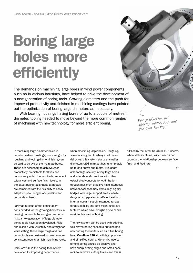
Boring large holes more efficiently
WIND POWER – BORING LARGE HOLES MORE EFFICIENTLY
In machining large diameter holes in nodular cast-iron castings, tool strength for roughing and tool rigidity for finishing can be said to be two of the main attributes. These are necessary to achieve good productivity, predictable tool-lives and consistency within the required component tolerances and surface finish levels. In the latest boring tools these attributes are combined with the flexibility to easily adapt tools to the type of operation and demands at hand.
Partly as a result of the boring opera-tions needed for the growing diameters in bearing houses, hubs and gearbox hous-ings, a new generation of large-diameter boring tools have been developed. Rigid and reliable with versatility and straightfor-ward setting, these large rough and fine boring tools are designed to provide more consistent results at high machining rates.
CoroBore® XL is the boring tool system developed for improving performance
when machining larger holes. Roughing, semi-finishing and finishing in all mate-rial types, this system starts at smaller diameters (298 mm) but has its emphasis up to and above one metre. It is adapt-able for high security in very large bores and extends and combines with other established concepts for optimization through maximum stability. Rigid interfaces between tool-assembly items, high-rigidity bridges with large support areas, newly-designed stop-plates for efficient setting, internal coolant supply, extended ranges for adjustability and light-weight units are features which have brought a new bench-mark to this area of boring.
The new system can be used with existing, well-proven boring concepts but also has new cutting tool units such as a fine boring head CoroBore 826 XL with high precision and simplified setting. Generally, inserts for fine boring should be positive and have sharp cutting edges and small nose radii to minimize cutting forces and this is
fulfilled by the latest CoroTurn 107 inserts. When stability allows, Wiper inserts can optimize the relationship between surface finish and feed rate.
>>
The demands on machining large bores in wind power components, such as in various housings, have helped to drive the development of a new generation of boring tools. Growing diameters and the push for improved productivity and finishes in machining castings have pointed out the optimization of boring large diameters as necessary. With bearing housings having bores of up to a couple of metres in diameter, tooling needed to move beyond the more common ranges of machining with new technology for more efficient boring.
For production of bearing house, hub
and
gearbox housing!
18
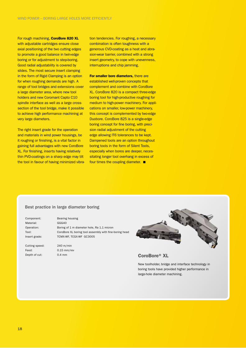
For rough machining, CoroBore 820 XL with adjustable cartridges ensure close axial positioning of the two cutting edges to promote a good balance in twin-edge boring or for adjustment to step-boring. Good radial adjustability is covered by slides. The most secure insert clamping in the form of Rigid Clamping is an option for when roughing demands are high. A range of tool bridges and extensions cover a large diameter area, where new tool holders and new Coromant Capto C10 spindle interface as well as a large cross-section of the tool bridge, make it possible to achieve high performance machining at very large diameters.
The right insert grade for the operation and materials in wind power housings, be it roughing or finishing, is a vital factor in gaining full advantages with new CoroBore XL. For finishing, inserts having relatively thin PVD-coatings on a sharp edge may tilt the tool in favour of having minimized vibra-
tion tendencies. For roughing, a necessary combination is often toughness with a generous CVD-coating as a heat and abra-sion-wear barrier, combined with a strong insert geometry, to cope with unevenness, interruptions and chip jamming.
For smaller bore diameters, there are established well-proven concepts that complement and combine with CoroBore XL. CoroBore 820 is a compact three-edge boring tool for high-productive roughing for medium to high-power machinery. For appli-cations on smaller, low-power machinery, this concept is complemented by two-edge Duobore. CoroBore 825 is a single-edge boring concept for fine boring, with preci-sion radial adjustment of the cutting edge allowing IT6 tolerances to be kept. Dampened tools are an option throughout boring tools in the form of Silent Tools, especially when bores are deeper, neces-sitating longer tool overhang in excess of four times the coupling diameter. n
New toolholder, bridge and interface technology in
boring tools have provided higher performance in
large-hole diameter machining.
Component: Bearing housing
Material: GGG40
Operation: Boring of 1 m diameter hole, Ra 1.1 micron
Tool: CoroBore XL boring tool assembly with fine-boring head
Insert grade: TCMX-WF, TCGX-WF GC3005
Cutting speed: 240 m/min
Feed: 0.15 mm/rev
Depth of cut: 0.4 mm
Best practice in large diameter boring
CoroBore® XL
WIND POWER – BORING LARGE HOLES MORE EFFICIENTLY
19
WIND POWER – MORE COMPETITIVE MILLING METHODS
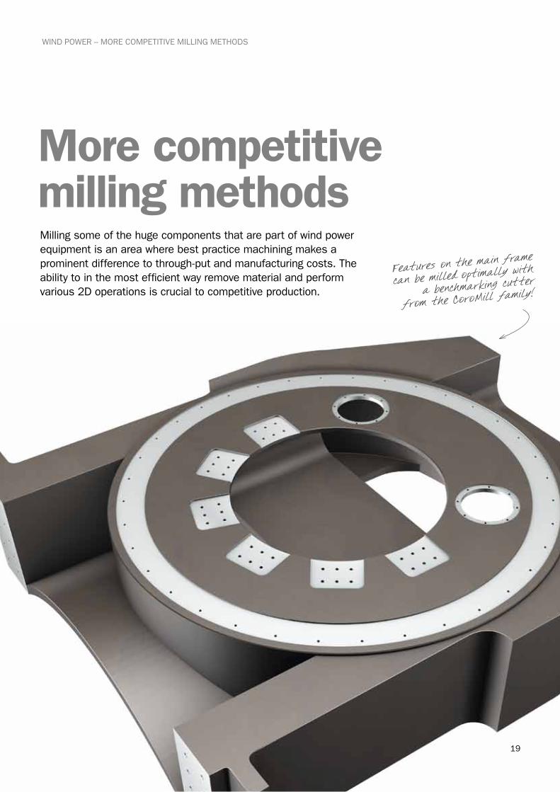
More competitive milling methodsMilling some of the huge components that are part of wind power equipment is an area where best practice machining makes a prominent difference to through-put and manufacturing costs. The ability to in the most efficient way remove material and perform various 2D operations is crucial to competitive production.
Features on the main frame
can be milled optimally with
a benchmarking cutter
from the CoroMill family!
20
Face milling and square shoulder milling dominate as operations as in amount of material removed through being the operations employed to machine many of the contact and bearing faces on cast-ings. As such they are rated in capability in metal removal rate, leaving a satisfac-tory surface and with good tool life to maximize machine running time.
With much of the workpiece material being some grade of nodular cast iron, various degrees of milling cutter dedica-tion is decisive for good performance. And this is when recent tool develop-ments have provided some interesting solutions.
Face milling was one of the first areas where the indexable insert was applied to tooling and where a lot of progress has been made since. For plain face milling of short-chipping materials, a 45- or 65-degree entering angle is generally regarded as first choice as the combina-tion of feed-rate capability, cutting force balance for often-needed tool overhang, entry-into and exit-out of cut advantage, cutting edge strength and lower work-piece frittering is superior.
Square-shoulder milling, edging, profiling and various end milling operations limit the entering angle of the cutter to 90 degrees making certain additional cutter properties essential while also opening up new possibilities. Round insert cutters also warrant consideration for some operations when the strongest of cutting edges make a difference to performance and security.
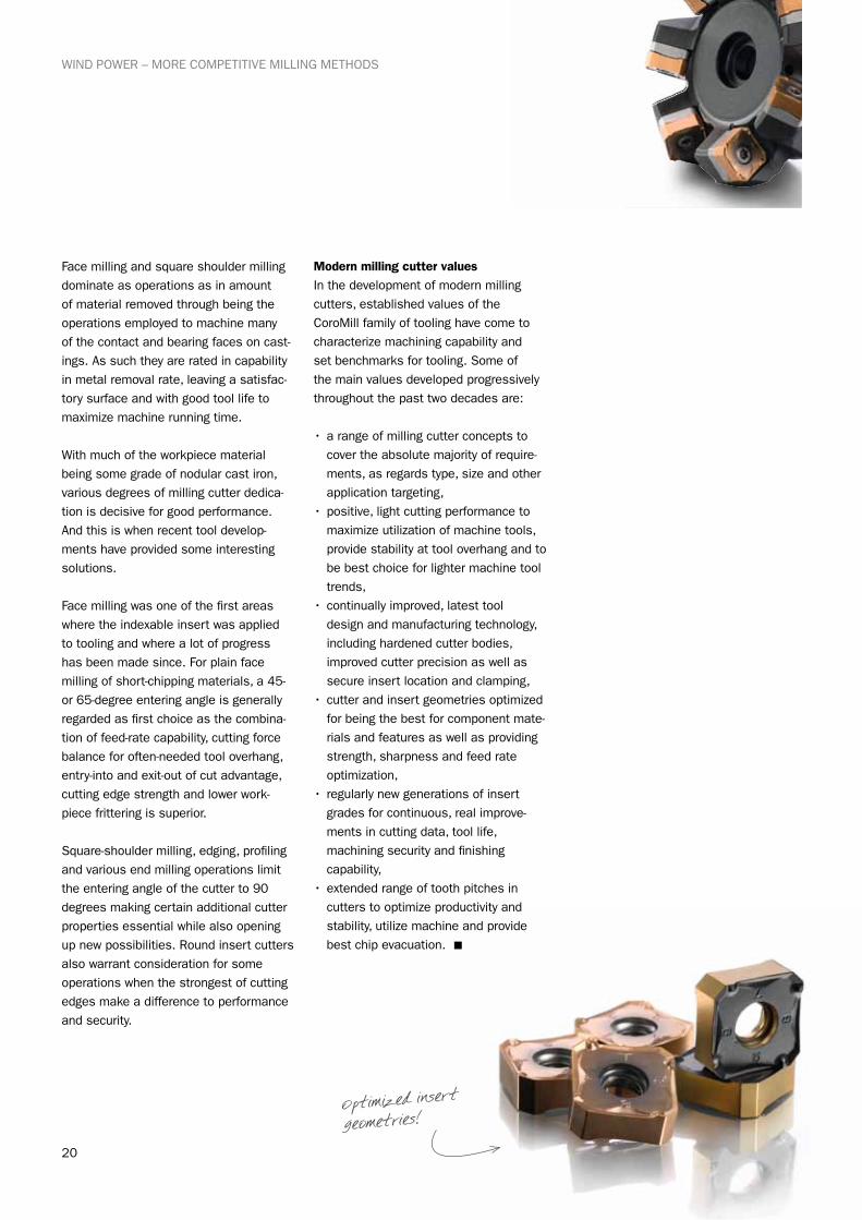
Modern milling cutter valuesIn the development of modern milling cutters, established values of the CoroMill family of tooling have come to characterize machining capability and set benchmarks for tooling. Some of the main values developed progressively throughout the past two decades are:
•a range of milling cutter concepts to cover the absolute majority of require-ments, as regards type, size and other application targeting,
•positive, light cutting performance to maximize utilization of machine tools, provide stability at tool overhang and to be best choice for lighter machine tool trends,
•continually improved, latest tool design and manufacturing technology, including hardened cutter bodies, improved cutter precision as well as secure insert location and clamping,
•cutter and insert geometries optimized for being the best for component mate-rials and features as well as providing strength, sharpness and feed rate optimization,
• regularly new generations of insert grades for continuous, real improve-ments in cutting data, tool life, machining security and finishing capability,
•extended range of tooth pitches in cutters to optimize productivity and stability, utilize machine and provide best chip evacuation. n
Optimized insert
geometries!
WIND POWER – MORE COMPETITIVE MILLING METHODS
21
High feed rate with
soft cutting action is
ideal for milling hubs
and housings!
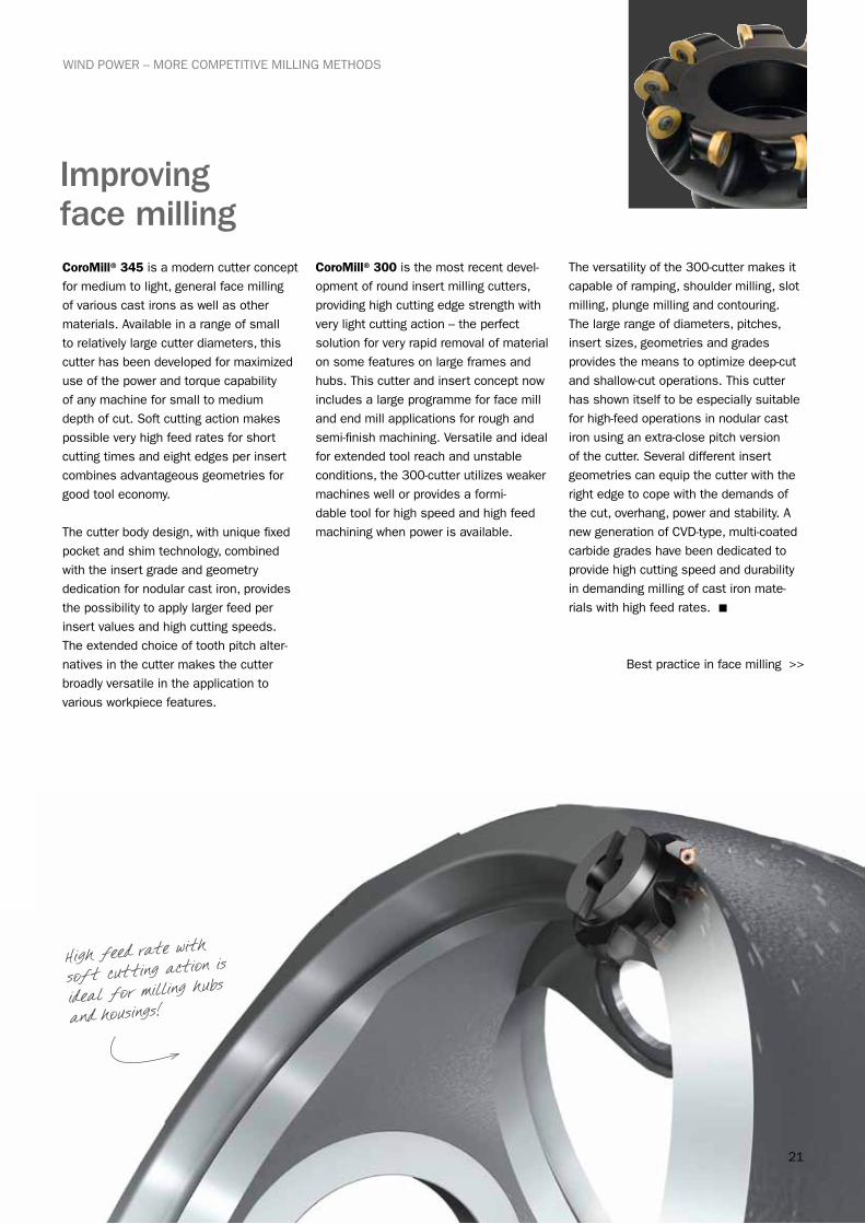
CoroMill® 345 is a modern cutter concept for medium to light, general face milling of various cast irons as well as other materials. Available in a range of small to relatively large cutter diameters, this cutter has been developed for maximized use of the power and torque capability of any machine for small to medium depth of cut. Soft cutting action makes possible very high feed rates for short cutting times and eight edges per insert combines advantageous geometries for good tool economy.
The cutter body design, with unique fixed pocket and shim technology, combined with the insert grade and geometry dedication for nodular cast iron, provides the possibility to apply larger feed per insert values and high cutting speeds. The extended choice of tooth pitch alter-natives in the cutter makes the cutter broadly versatile in the application to various workpiece features.
CoroMill® 300 is the most recent devel-opment of round insert milling cutters, providing high cutting edge strength with very light cutting action – the perfect solution for very rapid removal of material on some features on large frames and hubs. This cutter and insert concept now includes a large programme for face mill and end mill applications for rough and semi-finish machining. Versatile and ideal for extended tool reach and unstable conditions, the 300-cutter utilizes weaker machines well or provides a formi-dable tool for high speed and high feed machining when power is available.
The versatility of the 300-cutter makes it capable of ramping, shoulder milling, slot milling, plunge milling and contouring. The large range of diameters, pitches, insert sizes, geometries and grades provides the means to optimize deep-cut and shallow-cut operations. This cutter has shown itself to be especially suitable for high-feed operations in nodular cast iron using an extra-close pitch version of the cutter. Several different insert geometries can equip the cutter with the right edge to cope with the demands of the cut, overhang, power and stability. A new generation of CVD-type, multi-coated carbide grades have been dedicated to provide high cutting speed and durability in demanding milling of cast iron mate-rials with high feed rates. n
Best practice in face milling >>
Improving face milling
WIND POWER – MORE COMPETITIVE MILLING METHODS
22
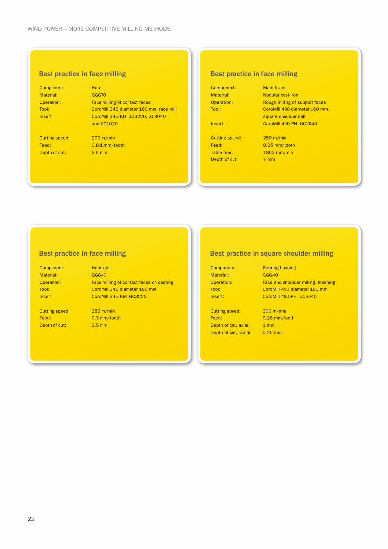
Component: Hub
Material: GGG70
Operation: Face milling of contact faces
Tool: CoroMill 345 diameter 160 mm, face mill
Insert: CoroMill 345-KH GC3220, GC3040
and GC1020
Cutting speed: 200 m/min
Feed: 0.8-1 mm/tooth
Depth of cut: 2-5 mm
Component: Main frame
Material: Nodular cast-iron
Operation: Rough milling of support faces
Tool: CoroMill 490 diameter 160 mm,
square shoulder mill
Insert: CoroMill 490-PH, GC2040
Cutting speed: 250 m/min
Feed: 0.25 mm/tooth
Table feed: 1863 mm/min
Depth of cut: 7 mm
Component: Housing
Material: GGG40
Operation: Face milling of contact faces on casting
Tool: CoroMill 345 diameter 160 mm
Insert: CoroMill 345-KM GC3220
Cutting speed: 280 m/min
Feed: 0.3 mm/tooth
Depth of cut: 3.5 mm
Component: Bearing housing
Material: GGG40
Operation: Face and shoulder milling, finishing
Tool: CoroMill 490 diameter 160 mm
Insert: CoroMill 490-PH GC3040
Cutting speed: 300 m/min
Feed: 0.28 mm/tooth
Depth of cut, axial: 1 mm
Depth of cut, radial: 0.25 mm
Best practice in face milling Best practice in face milling
Best practice in face milling Best practice in square shoulder milling
WIND POWER – MORE COMPETITIVE MILLING METHODS

23
CoroMill® 490 represents a unique new concept in milling cutter technology: a light-cutting, four-edge insert solution with the capability of taking up to 10 mm depths of cut, while also providing high finishing capability through wiper-edge technology to generate face and shoulder surfaces. With a large diameter range, this versatile concept leads as a square-shoulder face mill and as an end mill. High metal removal rates are possible also in low-powered machines through the light-cutting performance of the innovative concept of the 490 cutter. The range of insert geometries and grades and cutter pitch alternatives allow a lot of scope in improving various operations on wind power components. Face milling, shoulder milling, edge and contour milling, slot milling and efficient circular interpolation of bores are typical. The option of over-sized milling cutters and under-sized shanks provides added capability for reaching into housings and applying the light-cutting 490 cutter on smaller machines.
The CoroMill® 390 is the benchmark cutter in end milling and long-edge milling that has continuously evolved since its introduction. It complements CoroMill 490 in providing broad optimiza-tion possibilities for numerous applica-tions. The pioneering end mill concept with a new type of positive-geometry insert with a long cutting edge gave a new performance level, such as for pock-eting with varying depths of cut.
Today, the 390 concept has been adopted in a large programme of very versatile cutters covering many appli-cations, including long, slender tools having vibration dampening shanks. It also provides ramping and plunge-milling capability with the long-edge version providing a high removal rate for edges and deep shoulders as well as efficient circular milling of bores. n
Improving shoulder and end milling
WIND POWER – MORE COMPETITIVE MILLING METHODS
In the past, much of square shoulder milling, including end milling, was performed with triangular inserts as this was the only practical means with which to have the required edge clearance. Introducing square inserts posed a tool development chal-lenge. Improving tool performance was foremost but there had to be four effective edges to provide better tool-cost efficiency with good security. The concept would have to have both sufficient cutting edge clearance on a square insert, advanced insert geometry as well edge-strength to perform medium roughing through to the edge-precision for finishing shoulders and edges.
Selecting the right square
shoulder cutter for the
feature at hand is vital
for best practice!
Best practice in milling >>
24
WIND POWER – MORE COMPETITIVE MILLING METHODS
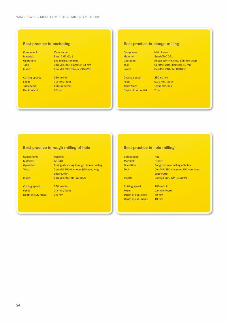
Component: Main frame
Material: Steel CMC 02.1
Operation: End milling, ramping
Tool: CoroMill 390 diameter 63 mm
Insert: CoroMill 390 18 mm GC4220
Cutting speed: 250 m/min
Feed: 0.2 mm/tooth
Table feed: 1263 mm/min
Depth of cut: 10 mm
Component: Main frame
Material: Steel CMC 02.1
Operation: Rough cavity milling, 125 mm deep
Tool: CoroMill 210 diameter 52 mm
Insert: CoroMill 210-PM GC1030
Cutting speed: 250 m/min
Feed: 0.32 mm/tooth
Table feed: 1958 mm/min
Depth of cut, radial: 2 mm
Component: Housing
Material: GGG40
Operation: Boring of casting through circular milling
Tool: CoroMill 390 diameter 100 mm, long
edge cutter
Insert: CoroMill 390-KM GC1020
Cutting speed: 250 m/min
Feed: 0.3 mm/tooth
Depth of cut, radial: 3.5 mm
Component: Hub
Material: GGG70
Operation: Rough circular milling of holes
Tool: CoroMill 390 diameter 100 mm, long
edge cutter
Insert: CoroMill 390-KM GC3040
Cutting speed: 180 m/min
Feed: 0.8 mm/tooth
Depth of cut, axial: 70 mm
Depth of cut, radial: 10 mm
Best practice in pocketing Best practice in plunge milling
Best practice in rough milling of hole Best practice in hole milling

25
WIND POWER – MORE COMPETITIVE MILLING METHODS
The CoroMill® 210 high feed milling cutter can be used for some face milling, ramping, circular milling and plunge milling. With a ten-degree entering angle, the cutter is capable of very high feed rates and consequently large removal rates. The small entering angle results in dominantly axial cutting forces, improving milling with longer tool reach, and a favourable chip-thinning effect. This cutter is unique in that it offers a constant chip thickness all the way up to maximum axial depth of cut. A constant maximum chip thickness is especially favourable in that there are much lower vibration tendencies.
The CoroMill® 200 round insert milling cutter is ideal for the really rough applica-tions. It offers extremely high cutting edge strength with very secure insert location – thus ensuring high reliability when roughing large, varying cast iron surfaces. This is a multi-purpose cutter for demanding conditions and material variations and a tool capable of providing high reliability in larger, more powerful machines with rigid set-ups. Wide optimi-zation for safe, efficient milling is provided with the range of cutter sizes and pitches, insert sizes and geometries with new insert grades to suit operations – always the problem solver when faced with rough castings and sand inclusion. n
Optimizing more exceptional demandsThere are some component features or material characteristics that are best machined or even only possible to machine efficiently, with milling cutters beyond the usual scope. In large castings there are flats, cavities and bores that have to be roughed initially and depending upon the size and demands of these, there are two productivity boosting types of cutters and methods that should always be considered.
High feed milling and plunge milling are modern, versatile CNC machining methods that are very suitable for when longer tool reach is needed. Making cavities, opening up cavities and holes can be performed effectively and are easy methods to apply. The best method for larger features is constant z-level roughing while smaller features are usually best made through plunge milling or helical interpolation.
Making cavities through plunge milling w
ith
a dedicated tool provides a very effic
ient
roughing method!
26
WIND POWER – TECHNOLOGY CHOICES FOR DEEP HOLE DRILLING
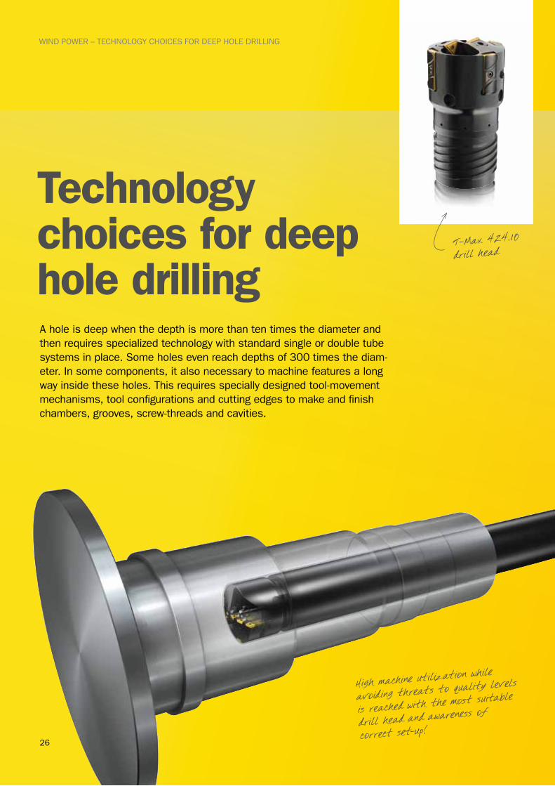
Technology choices for deep hole drillingA hole is deep when the depth is more than ten times the diameter and then requires specialized technology with standard single or double tube systems in place. Some holes even reach depths of 300 times the diam-eter. In some components, it also necessary to machine features a long way inside these holes. This requires specially designed tool-movement mechanisms, tool configurations and cutting edges to make and finish chambers, grooves, screw-threads and cavities.
High machine utilization while
avoiding threats to quality levels
is reached with the most suitable
drill head and awareness of
correct set-up!
T-Max 424.10 drill head
27
WIND POWER – TECHNOLOGY CHOICES FOR DEEP HOLE DRILLING
Tools and methods in the area of deep hole drilling and machining have seen recent developments which hugely benefit such applications like making the centre hole in main shafts for wind power units. Support-pad technology for drill heads is an integral part of and a recognized key factor for drilling performance. New developments in this part of tooling have contributed, along with insert and head designs, towards improved machining. With the right tooling system for deep hole drilling in place, success is very much the result of getting the small adjustments right. Using the best drill head with the recommended cutting data, a follow-up standard checklist should include: ensuring the best set-up, having acceptable chip evacuation, holding the required surface finish throughout a sufficiently long tool-life, achieving the demanded diameter-tolerance consist-ency and good hole-straightness. Examples of factors, vital in the set-up, are the alignment between drill head and component to avoid any bell-mouthing of hole and regular checks throughout the operation of the drill bush size.
High machine utilization is an important objective and drilling the centre hole in main shafts is best performed using a single tube system (STS). With the best drill head, such as CoroDrill 800.24, high penetration-rates and security levels can be combined for holes as deep as 150 x the diameter, up to 65mm. For larger holes, the T-Max 424.10 drill head with setting possibilities on the diameter, are the standard solution. To extend the hole diameter, beyond the standard solid-drilling range up to 130 mm, drilling followed by counterboring with T-Max 424.31 heads is an efficient method which overcomes machine tool power-limitations or as a finishing operation. CoroDrill and T-Max heads and equipment are modern, tools manufactured with the latest technology to provide the best deep hole processes. n
Component: Main shaft
Material: 34CrNiMo6
Operation: STS full drilling of 4.2 m deep hole
Tool: CoroDrill 424.10 diameter 300 mm
Insert: CoroDrill 424.9 GC1025
Cutting speed: 70 m/min
Feed: 0.27 mm/rev
Metal removal rate: 1164 cubic-cm/min
Machining time: 2 hours 57 minutes
Component: Main shaft
Material: 34CrNiMo6
Operation: STS counterboring 4.2 m drilled hole
Tool: CoroDrill 424.32
Insert: CoroDrill 424.9 GC1025
Cutting speed: 70 m/min
Feed: 0.30 mm/rev
Machining time: 3 hours 8 minutes
Best practice in deep hole drilling Best practice in finishing deep hole
28
WIND POWER – STEP BY STEP DRILLING IMPROVEMENTS
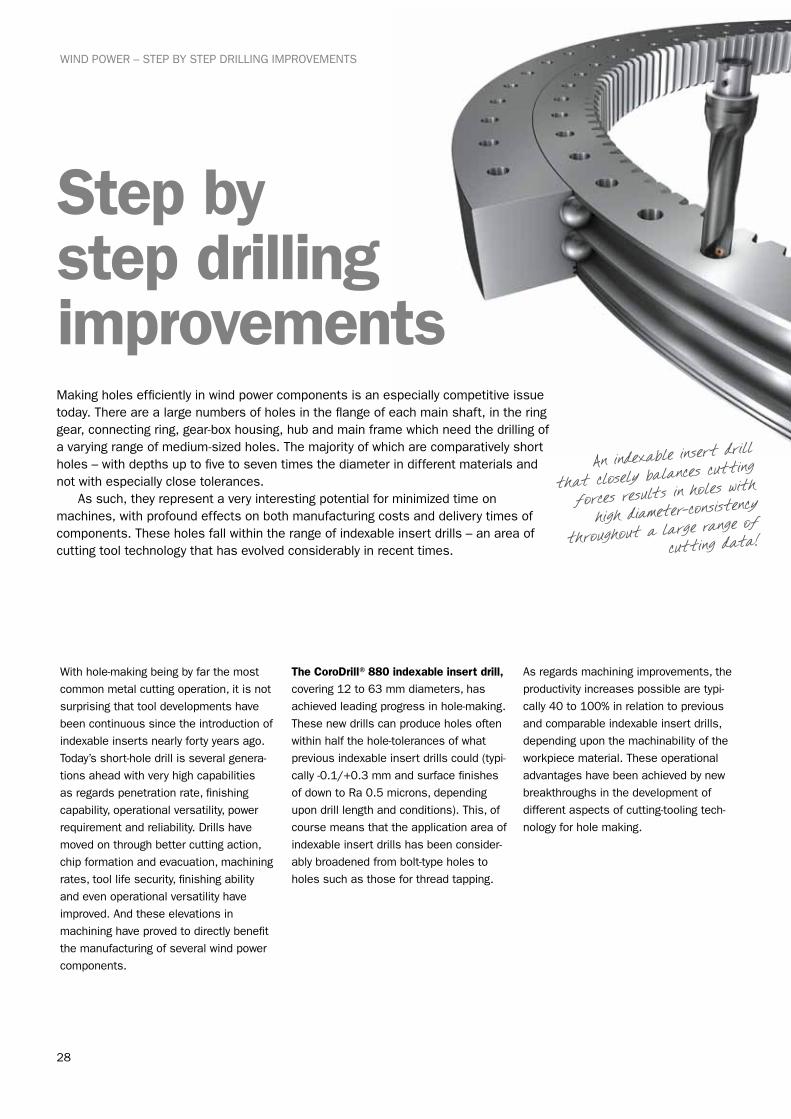
Step by step drilling improvementsMaking holes efficiently in wind power components is an especially competitive issue today. There are a large numbers of holes in the flange of each main shaft, in the ring gear, connecting ring, gear-box housing, hub and main frame which need the drilling of a varying range of medium-sized holes. The majority of which are comparatively short holes – with depths up to five to seven times the diameter in different materials and not with especially close tolerances. As such, they represent a very interesting potential for minimized time on machines, with profound effects on both manufacturing costs and delivery times of components. These holes fall within the range of indexable insert drills – an area of cutting tool technology that has evolved considerably in recent times.
With hole-making being by far the most common metal cutting operation, it is not surprising that tool developments have been continuous since the introduction of indexable inserts nearly forty years ago. Today’s short-hole drill is several genera-tions ahead with very high capabilities as regards penetration rate, finishing capability, operational versatility, power requirement and reliability. Drills have moved on through better cutting action, chip formation and evacuation, machining rates, tool life security, finishing ability and even operational versatility have improved. And these elevations in machining have proved to directly benefit the manufacturing of several wind power components.
The CoroDrill®880 indexable insert drill, covering 12 to 63 mm diameters, has achieved leading progress in hole-making. These new drills can produce holes often within half the hole-tolerances of what previous indexable insert drills could (typi-cally -0.1/+0.3 mm and surface finishes of down to Ra 0.5 microns, depending upon drill length and conditions). This, of course means that the application area of indexable insert drills has been consider-ably broadened from bolt-type holes to holes such as those for thread tapping.
As regards machining improvements, the productivity increases possible are typi-cally 40 to 100% in relation to previous and comparable indexable insert drills, depending upon the machinability of the workpiece material. These operational advantages have been achieved by new breakthroughs in the development of different aspects of cutting-tooling tech-nology for hole making.
An indexable insert drill
that closely balances cutting
forces results in holes with
high diameter-consistency
throughout a large range of
cutting data!
29
WIND POWER – STEP BY STEP DRILLING IMPROVEMENTS
The new Step Technology™ for 880 drill is unique in that it is achieved through the combined function of the central and peripheral inserts when entering the workpiece. Cutting forces are optimized and distributed step-by-step between the inserts, with the resulting close balance having a very positive influence on the performance and results of the drill. This also leads to that the 880 drill makes holes with the same dimension whatever the cutting data. This is a high-tech solution developed with high-tech methods, made possible by the facilities that are available today by way of IT-technology coupled to new cutting action analysis. These advances in metal cutting took several years to achieve and needed a specially devel-oped drilling-monitoring programme to be perfected. As a result, when drilling, the cutting forces generated by the 880 drill are considerably smaller than those of any previous indexable insert drill.
Making a drill that is closely balanced for one or few specific diameters is relatively straightforward. But making a drill that is balanced for every specific diameter throughout its diameter-adjust-ment range is a lot more demanding technically. In the 880 drill, this has been solved by the centre and peripheral insert being moved radially in the drill to achieve balanced cutting action in the large diam-eter adjustment ranges.
The 880 drill also has chip channels that have been carefully optimized as regards the constant compromise in drills - the balance between chip evacuation and drill stiffness. Also, the area immediately behind the inserts has a new design to provide the chips with a natural exit from the cutting zone into a smooth flow-path down the flute of the drill.
Insert geometries and grades have undergone considerable development and, in the 880 drill become even more of an integrated performance-part of the drill itself. Inserts have four true cutting edges with a completely new type of cutting action. Geometries have been dedicated and thereby optimized for the two different insert positions on the drill: the centre insert, where cutting speed approaches zero towards the centre, and the peripheral inserts, now capable of even higher cutting speeds and feeds. Furthermore, Wiper-edge technology has been incorporated on peripheral inserts, where the surface finish is generated.
Combined with developments in insert grades, resulting in new grades for the 880 drill, grade-geometry combinations can be selected for far-reaching opti-mization to meet different demands of the centre and peripheral inserts to the component material, machining condi-tions and new levels of cutting data. n
Component: Housing
Material: GGG40
Operation: Drilling of pre-cast holes
Tool: CoroDrill 880 diameter 39 mm
Inserts: CoroDrill 880 GC1044/4024
Cutting speed: 280 m/min
Feed: 0.35 mm/rev
Component: Slewing ring
Material: Alloy steel
Operation: Drilling of multiple holes, depth of 5xD
Tool: CoroDrill 880 diameter 39 mm
Inserts: CoroDrill 880 GC1044/2024
Cutting speed: 160 m/min
Feed: 230 mm/min
Best practice in drilling Best practice in drilling

30
WIND POWER – THE BEST OF TOOL HOLDING
The best of tool holding
Coromant Capto® is the most stable tool-holding system available and is now an ISO-standard. It is a modular, quick-change system suitable for rotating and stationary tools, and as such can be used throughout an entire machine shop with different machinery. As a modular inter-face, it combines cutting tools, adaptors, extensions and basic holders to great flexibility.
The tapered polygon coupling is unique in transmitting the levels of torque and providing the highest great stability and accuracy. Different clamping methods give the system the versatility to suit various machine types and it has been provided with internal coolant facilities directed to the cutting edge, with high pressure coolant options. There are also exten-sions and reductions to provide set-up combinations with other C-sizes.
A larger coupling size C10 is now avail-able as standard for heavier machining. The Coromant Capto system is thus avail-able for a complete range of sizes which now also includes the larger end of the programme to extend optimization. The C10 size improves performance in larger machines by allowing higher feeds and depths of cut. Coromant Capto C10 has a flange diameter of 100 mm which means a coupling capable of the heavier loads in many milling applications and very high stability in turning. The Coromant Capto system provides very high bending stiffness for demanding operations and high accuracy at heavy loads. The new C10 standard ensures that tool holding is not the weakest link in the chain from machine to cutting edge at the heavier end of machining. n
Tool holding has a dramatic influence on machining in being the vital link it is in the chain of factors from machine to cutting edge. The interface between spindle and tooling and adaptors so directly affects capability in that it can directly limit or ensure competitive levels of cutting data, security and the results.
Modular tool holding today
should be about strength,
accuracy, handling, availability,
rationalization and versatility!
31
WIND POWER – THE BEST OF TOOL HOLDING
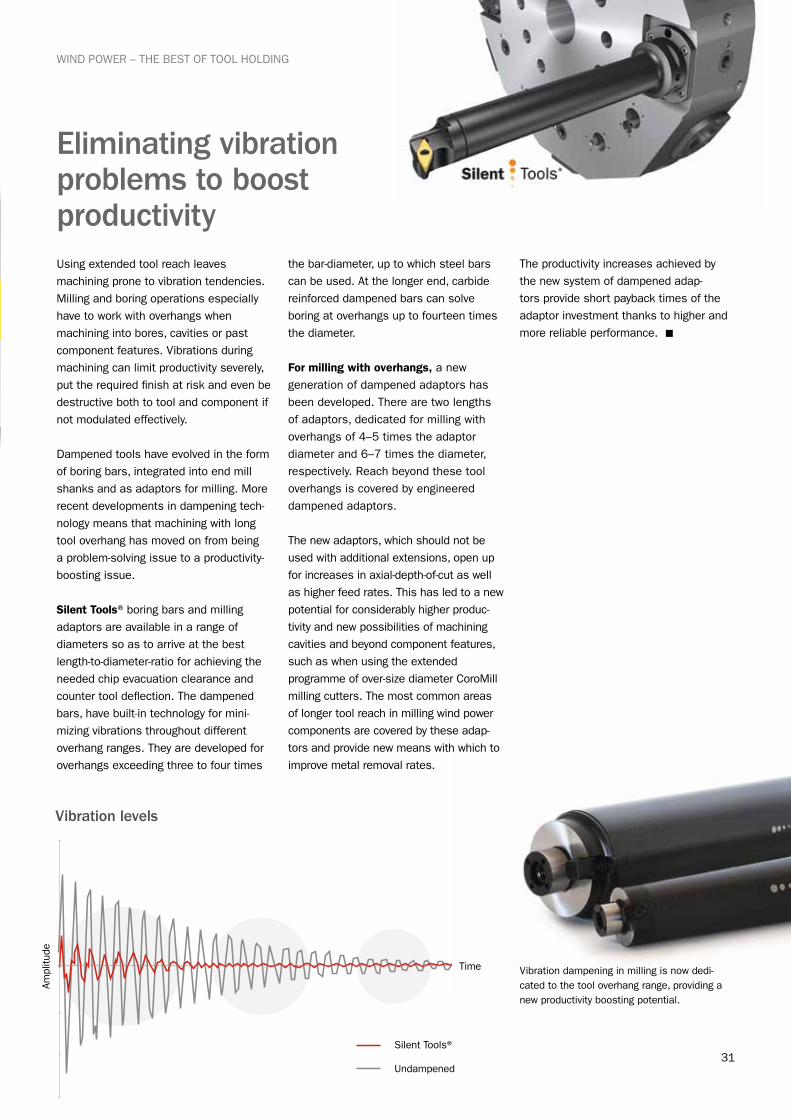
Using extended tool reach leaves machining prone to vibration tendencies. Milling and boring operations especially have to work with overhangs when machining into bores, cavities or past component features. Vibrations during machining can limit productivity severely, put the required finish at risk and even be destructive both to tool and component if not modulated effectively.
Dampened tools have evolved in the form of boring bars, integrated into end mill shanks and as adaptors for milling. More recent developments in dampening tech-nology means that machining with long tool overhang has moved on from being a problem-solving issue to a productivity-boosting issue.
Silent Tools® boring bars and milling adaptors are available in a range of diameters so as to arrive at the best length-to-diameter-ratio for achieving the needed chip evacuation clearance and counter tool deflection. The dampened bars, have built-in technology for mini-mizing vibrations throughout different overhang ranges. They are developed for overhangs exceeding three to four times
the bar-diameter, up to which steel bars can be used. At the longer end, carbide reinforced dampened bars can solve boring at overhangs up to fourteen times the diameter.
For milling with overhangs, a new generation of dampened adaptors has been developed. There are two lengths of adaptors, dedicated for milling with overhangs of 4–5 times the adaptor diameter and 6–7 times the diameter, respectively. Reach beyond these tool overhangs is covered by engineered dampened adaptors.
The new adaptors, which should not be used with additional extensions, open up for increases in axial-depth-of-cut as well as higher feed rates. This has led to a new potential for considerably higher produc-tivity and new possibilities of machining cavities and beyond component features, such as when using the extended pro gramme of over-size diameter CoroMill milling cutters. The most common areas of longer tool reach in milling wind power components are covered by these adap-tors and provide new means with which to improve metal removal rates.
The productivity increases achieved by the new system of dampened adap-tors provide short payback times of the adaptor investment thanks to higher and more reliable performance. n
Eliminating vibration problems to boost productivity
Ampl
itude
Time
Vibration levels
Undampened
Silent Tools®
Vibration dampening in milling is now dedi-cated to the tool overhang range, providing a new productivity boosting potential.

Head office: AB Sandvik Coromant SE-811 81 Sandviken, Swedenwww.sandvik.coromant.com E-mail: [email protected]
C-2940:136 ENG/01 © AB Sandvik Coromant 2011.06This folder is printed on recyclable paper. Printed in Sweden at Sandvikens Tryckeri.