ES 201 803-7 - V1.1.1 - Dynamic synchronous Transfer … · - Part 4 specifies the physical layer...
40
ETSI ES 201 803-7 V1.1.1 (2002-03) ETSI Standard Dynamic synchronous Transfer Mode (DTM); Part 7: Ethernet over DTM Mapping
Transcript of ES 201 803-7 - V1.1.1 - Dynamic synchronous Transfer … · - Part 4 specifies the physical layer...
ETSI ES 201 803-7 V1.1.1 (2002-03)
ETSI Standard
Dynamic synchronous Transfer Mode (DTM);Part 7: Ethernet over DTM Mapping
ETSI
ETSI ES 201 803-7 V1.1.1 (2002-03)2
Reference DES/SPAN-130007
Keywords DTM, Ethernet, LAN, transmission
ETSI
650 Route des Lucioles F-06921 Sophia Antipolis Cedex - FRANCE
Tel.: +33 4 92 94 42 00 Fax: +33 4 93 65 47 16
Siret N° 348 623 562 00017 - NAF 742 C
Association à but non lucratif enregistrée à la Sous-Préfecture de Grasse (06) N° 7803/88
Important notice
Individual copies of the present document can be downloaded from: http://www.etsi.org
The present document may be made available in more than one electronic version or in print. In any case of existing or perceived difference in contents between such versions, the reference version is the Portable Document Format (PDF).
In case of dispute, the reference shall be the printing on ETSI printers of the PDF version kept on a specific network drive within ETSI Secretariat.
Users of the present document should be aware that the document may be subject to revision or change of status. Information on the current status of this and other ETSI documents is available at
http://portal.etsi.org/tb/status/status.asp
If you find errors in the present document, send your comment to: [email protected]
Copyright Notification
No part may be reproduced except as authorized by written permission. The copyright and the foregoing restriction extend to reproduction in all media.
© European Telecommunications Standards Institute 2002.
All rights reserved.
ETSI
ETSI ES 201 803-7 V1.1.1 (2002-03)3
Contents
Intellectual Property Rights ................................................................................................................................5
Foreword.............................................................................................................................................................5
Introduction ........................................................................................................................................................6
1 Scope ........................................................................................................................................................7
2 References ................................................................................................................................................7
3 Definitions and abbreviations...................................................................................................................7 3.1 Definitions..........................................................................................................................................................7 3.2 Abbreviations .....................................................................................................................................................8
4 Service overview......................................................................................................................................9 4.1 DLT service overview........................................................................................................................................9 4.2 DLE service overview......................................................................................................................................10
5 System overview ....................................................................................................................................10 5.1 DLT system overview ......................................................................................................................................10 5.1.1 Channels in DLT.........................................................................................................................................10 5.1.2 DLT client traffic forwarding .....................................................................................................................11 5.2 DLE system overview ......................................................................................................................................11 5.2.1 Channels in DLE.........................................................................................................................................11 5.2.2 Packet forwarding in the DLE Client..........................................................................................................12 5.2.3 Address learning in the DLE Client............................................................................................................12 5.2.4 Redundant DLE Servers .............................................................................................................................12 5.3 VLAN Support .................................................................................................................................................13
6 Service Interfaces ...................................................................................................................................13 6.1 Transport view..................................................................................................................................................13 6.2 Control view.....................................................................................................................................................14
7 Detailed Protocol Description ................................................................................................................14 7.1 DCMI interaction of DLE and DLT.................................................................................................................14 7.2 DCAI interaction of DLE and DLT..................................................................................................................16 7.3 DLT operation ..................................................................................................................................................16 7.3.1 Startup.........................................................................................................................................................16 7.3.2 Normal operation ........................................................................................................................................17 7.3.3 Shutdown ....................................................................................................................................................17 7.3.4 Restart .........................................................................................................................................................17 7.3.5 Peer disconnect ...........................................................................................................................................17 7.3.6 Unknown Message Types and extensions ..................................................................................................17 7.4 DLE operation ..................................................................................................................................................18 7.4.1 Server startup ..............................................................................................................................................18 7.4.2 Server shutdown .........................................................................................................................................18 7.4.3 Server restart ...............................................................................................................................................18 7.4.4 New server connected to the DLE segment ................................................................................................19 7.4.5 Server disconnection...................................................................................................................................19 7.4.5.1 Removal of server to server channel .....................................................................................................19 7.4.5.2 Server removal of channel between server and client ...........................................................................19 7.4.6 Client start up..............................................................................................................................................19 7.4.7 Client restart................................................................................................................................................20 7.4.8 Client disconnect ........................................................................................................................................20 7.4.9 Address resolution ......................................................................................................................................21 7.4.9.1 Forwarding Ethernet frames with unknown destination .......................................................................22 7.4.9.2 Fast address announce...........................................................................................................................22 7.4.10 Flush mechanism ........................................................................................................................................22 7.4.11 Normal server operation .............................................................................................................................23 7.4.12 SCC Filtering ..............................................................................................................................................24
ETSI
ETSI ES 201 803-7 V1.1.1 (2002-03)4
7.4.13 Unknown message types.............................................................................................................................24
8 Messages ................................................................................................................................................24 8.1 General Message Format..................................................................................................................................24 8.1.1 Representing Ethernet addresses.................................................................................................................25 8.2 DLT messages ..................................................................................................................................................25 8.2.1 DLT_REGISTER .......................................................................................................................................25 8.2.1.1 Message format .....................................................................................................................................25 8.3 DLE messages ..................................................................................................................................................26 8.3.1 DLE_REGISTER .......................................................................................................................................26 8.3.1.1 Message format .....................................................................................................................................27 8.3.2 DLE_REGISTER_RESPONSE..................................................................................................................27 8.3.2.1 Message format .....................................................................................................................................27 8.3.3 DLE_AR_REQUEST .................................................................................................................................27 8.3.3.1 Message format .....................................................................................................................................28 8.3.4 DLE_AR_ANNOUNCE.............................................................................................................................28 8.3.4.1 Message format .....................................................................................................................................28 8.3.5 DLE_WAIT_FOR_FLUSH........................................................................................................................29 8.3.5.1 Message format .....................................................................................................................................29 8.3.6 DLE_FLUSH..............................................................................................................................................29 8.3.6.1 Message format .....................................................................................................................................30 8.3.7 DLE_AUTHENTICATE............................................................................................................................30 8.3.8 DLE_SERVER_REGISTER ......................................................................................................................30 8.3.8.1 Message format .....................................................................................................................................30 8.3.9 DLE_CLIENT_DISCONNECTED............................................................................................................31 8.3.9.1 Message format .....................................................................................................................................31
9 Ethernet encapsulation ...........................................................................................................................31 9.1 Ethernet packets with an 802.1Q tag ................................................................................................................32 9.2 Ethernet packets without 802.1Q tag................................................................................................................32 9.3 Valid and invalid VLAN information ..............................................................................................................33
10 Appendices .............................................................................................................................................33 10.1 Constants ..........................................................................................................................................................33 10.2 Configuration Parameters DLT ........................................................................................................................34 10.2.1 DLT Client Configuration ..........................................................................................................................34 10.3 Configuration parameters DLE ........................................................................................................................35 10.3.1 DLEC configuration ...................................................................................................................................35 10.3.1 DLES configuration....................................................................................................................................37
Annex A (informative): Bibliography...................................................................................................39
History ..............................................................................................................................................................40
ETSI
ETSI ES 201 803-7 V1.1.1 (2002-03)5
Intellectual Property Rights IPRs essential or potentially essential to the present document may have been declared to ETSI. The information pertaining to these essential IPRs, if any, is publicly available for ETSI members and non-members, and can be found in ETSI SR 000 314: "Intellectual Property Rights (IPRs); Essential, or potentially Essential, IPRs notified to ETSI in respect of ETSI standards", which is available from the ETSI Secretariat. Latest updates are available on the ETSI Web server (http://webapp.etsi.org/IPR/home.asp).
Pursuant to the ETSI IPR Policy, no investigation, including IPR searches, has been carried out by ETSI. No guarantee can be given as to the existence of other IPRs not referenced in ETSI SR 000 314 (or the updates on the ETSI Web server) which are, or may be, or may become, essential to the present document.
Foreword This ETSI Standard (ES) has been produced by ETSI Technical Committee Services and Protocols for Advanced Networks (SPAN), and is now submitted for the ETSI standards Membership Approval Procedure.
The present document is part 7 of a multi-part deliverable covering the Dynamic Synchronous Transfer Mode (DTM), as identified below:
Part 1: "System description";
Part 2: "System characteristics";
Part 3: "Physical Protocol";
Part 4: "Mapping of DTM frames into SDH containers";
Part 5: "Mapping of PDH over DTM";
Part 6: "Mapping of SDH over DTM";
Part 7: "Ethernet over DTM Mapping";
Part 8: "Mapping of Frame relay over DTM";
Part 9: "Mapping of ATM over DTM";
Part 10: "Routeing and switching of IP flows over DTM";
Part 11: "Mapping of video streams over DTM";
Part 12: "Mapping of MPLS over DTM";
Part 13: "System description of sub-rate DTM".
ETSI
ETSI ES 201 803-7 V1.1.1 (2002-03)6
Introduction Dynamic synchronous Transfer Mode (DTM) is a time division multiplex and a circuit-switched network technique that combines switching and transport. The present document specifying the DTM system and protocols is divided into 13 parts.
The present document (part 7) describes the method by which Ethernet [3] packets are carried over DTM.
The topics of the other parts are as follows:
- Part 1 introduces DTM and describes the service over a unidirectional data channel;
- Part 2 includes system aspects that are mandatory or optional for nodes from different vendors to interoperate. These system aspects are addressing, routing, synchronization and channel management. The interworking granularity should be at node level, such that nodes from different vendors can interoperate with regard to well-defined functions;
- Part 3 specifies the physical layer protocol for 8b/10b encoding based physical links;
- Part 4 specifies the physical layer protocol for SDH/SONET VC4 container based physical links;
- The transport of various tributary signals is specified for PDH (part 5), SDH (part 6), Ethernet (part 7), Frame Relay (part 8), ATM (part 9), IP (part 10), Mapping of MPLS over DTM (part 11), and video streaming (part 12). Note that DTM can either run over SDH or carry it as a tributary.
- Finally, management aspects are standardized in part 13.
ETSI
ETSI ES 201 803-7 V1.1.1 (2002-03)7
1 Scope The present document specifies how Ethernet protocol is transported over DTM. The specification encapsulation of PDUs includes address resolution (mapping the Ethernet source and destination address to the correct DTM destination), DTM channel set-up, channel capacity modification, and Ethernet VLAN handling.
2 References The following documents contain provisions which, through reference in this text, constitute provisions of the present document.
• References are either specific (identified by date of publication and/or edition number or version number) or non-specific.
• For a specific reference, subsequent revisions do not apply.
• For a non-specific reference, the latest version applies.
[1] IETF RFC 1483 (July 1993): "Multiprotocol Encapsulation over ATM Adaptation Layer 5".
[2] IETF RFC 2684 (September 1999): "Multiprotocol Encapsulation over ATM Adaptation Layer 5" (Revision of RFC 1483)".
[3] IEEE 802.3 (1996): "IEEE Standard for Information technology; Telecommunications and information exchange between systems; Local and metropolitan area networks; Specific requirement; Part 3: Carrier Sense Multiple Access with Collision Detection (CSMA/CD) Access Method and Physical Layer Specifications".
[4] IEEE 802.2 (1994): "IEEE Standard for Information technology; Telecommunications and information exchange between systems; Local and metropolitan area networks; Specific requirements; Part 2: Logical Link Control".
[5] IEEE 802 (1990): "IEEE Standard for Local and Metropolitan Area Networks: Overview and Architecture ".
[6] IEEE 802.1D (1998): "IEEE Standard for Information technology; Telecommunications and information exchange between systems; IEEE standard for local and metropolitan area networks; Common specifications; Part 3: Media access control (MAC) Bridges".
[7] IEEE 802.1Q (1998): "IEEE Standards for Local and Metropolitan Area Networks: Virtual Bridged Local Area Networks".
[8] ETSI ES 201 803-1: "Dynamic synchronous Transfer Mode (DTM); Part 1: System Description".
3 Definitions and abbreviations
3.1 Definitions For the purposes of the present document, the following terms and definitions apply:
access node: node that supports an external network interface, contains an interworking function for an external network and uses the DTM service
channel: set of slots allocated from one source access node to one or more destination access nodes in a network
NOTE: The source and destination nodes can be the same, where the channel is internal to the node.
control channel: channel used for channel signalling and management
ETSI
ETSI ES 201 803-7 V1.1.1 (2002-03)8
data channel: channel used for transport of user data
domain: DTM network or part of a network that is managed by a particular commercial or administrative entity (carrier/operator)
DTM network: set of connected DTM nodes
NOTE: A DTM network may be single-domain, or multi-domain.
frame: set of slots forming an entity that is transmitted on a physical medium repeatedly every 125 µs (nominally), i.e. 8 000 frames/second
node: network element that contains DTM functions
node address: DTM network layer address of a node
slot: time slot within the frame being able to transport 64 bit of data or a number of special codes
switching: process of moving the data of a slot in both time and space, i.e. switching between different ports and changing slot numbers while maintaining the bandwidth and avoiding slot reordering within each channel
switch node: node that contains a switching function
3.2 Abbreviations For the purposes of the present document the following abbreviations apply:
ATM Asynchronous Transfer Mode ARR Address Resolution Request CCC Client-to-Client Channel CMI Channel Multiplexing Identifier CSC Client-to-Server Channel DCAI DTM Channel Adaptation Interface DCCI DTM Channel Control Interface DCAP-1 DTM Channel Adaptation Protocol 1 DCMI DTM Channel Management Interface DCP DTM Channel Protocol DLE DTM LAN Emulation DLEC DLE Client DLES DLE Server DLT DTM Ethernet LAN Transport DST DTM Service Type DSTI DTM Service Type Instance DTM Dynamic synchronous Transfer Mode IP Internet Protocol MAC Medium Access Control MIB Management Information Base PDU Protocol Data Unit RFC Request For Comment (IETF document) SCC Server-to-Client Channel SDH Synchronous Digital Hierarchy SSC Server-to-Server Channel TDM Time Division Multiplexing VLAN Virtual Local Area Network
ETSI
ETSI ES 201 803-7 V1.1.1 (2002-03)9
4 Service overview There are two different ways of transporting Ethernet traffic across a DTM network specified in the present document:
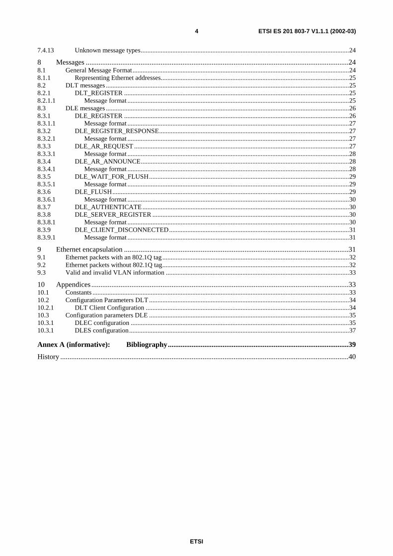
• DTM LAN Transport (DLT) is a very simple service where the DTM network is used to set up a tunnel between two DLT clients. Each DLT client is in its turn connected to a logical Ethernet switch. The logical Ethernet switch forwards packets between the DLT client and one or several Ethernet ports and/or other DLT clients.
• DTM LAN Emulation (DLE) provides the additional service of a distributed Ethernet switch function, allowing VLAN switching where two or more DLE Clients can be interconnected via the DTM network.
The characteristics of the Ethernet transport utilize the characteristics of the DTM transport service providing traffic isolation and very low delay variation. The DTM network allows the distance limitation of connected Ethernets to be removed.
Ethernet is a connectionless technology, meaning that data is transported in packets that are handled independently of each other. The packets carry sufficient information to identify the Ethernet destination of the packet. DTM, on the other hand, is connection-oriented; meaning that data is transported using an established connection. During the establishment of the connection sufficient state information is stored in the switches along the path from source to destination. In order to forward the data, each data item does not need to carry information specifying the destination..
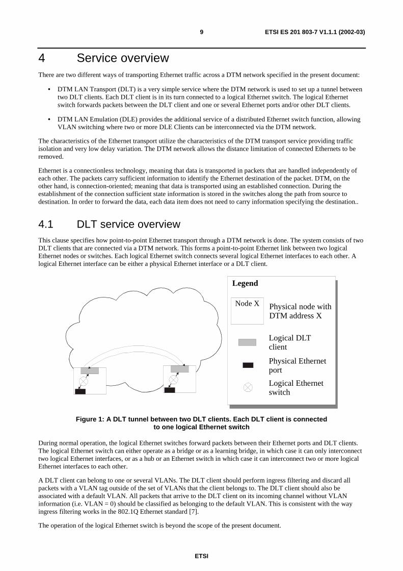
4.1 DLT service overview This clause specifies how point-to-point Ethernet transport through a DTM network is done. The system consists of two DLT clients that are connected via a DTM network. This forms a point-to-point Ethernet link between two logical Ethernet nodes or switches. Each logical Ethernet switch connects several logical Ethernet interfaces to each other. A logical Ethernet interface can be either a physical Ethernet interface or a DLT client.
Node X Physical node withDTM address X
Logical DLTclient
Logical Ethernetswitch
Physical Ethernetport
Legend
Figure 1: A DLT tunnel between two DLT clients. Each DLT client is connected to one logical Ethernet switch
During normal operation, the logical Ethernet switches forward packets between their Ethernet ports and DLT clients. The logical Ethernet switch can either operate as a bridge or as a learning bridge, in which case it can only interconnect two logical Ethernet interfaces, or as a hub or an Ethernet switch in which case it can interconnect two or more logical Ethernet interfaces to each other.
A DLT client can belong to one or several VLANs. The DLT client should perform ingress filtering and discard all packets with a VLAN tag outside of the set of VLANs that the client belongs to. The DLT client should also be associated with a default VLAN. All packets that arrive to the DLT client on its incoming channel without VLAN information (i.e. VLAN = 0) should be classified as belonging to the default VLAN. This is consistent with the way ingress filtering works in the 802.1Q Ethernet standard [7].
The operation of the logical Ethernet switch is beyond the scope of the present document.
ETSI
ETSI ES 201 803-7 V1.1.1 (2002-03)10
A DLT client can also be connected as an interface to a regular protocol stack, e.g. an IP routing process. The DLT client should then behave as a normal Ethernet interface.
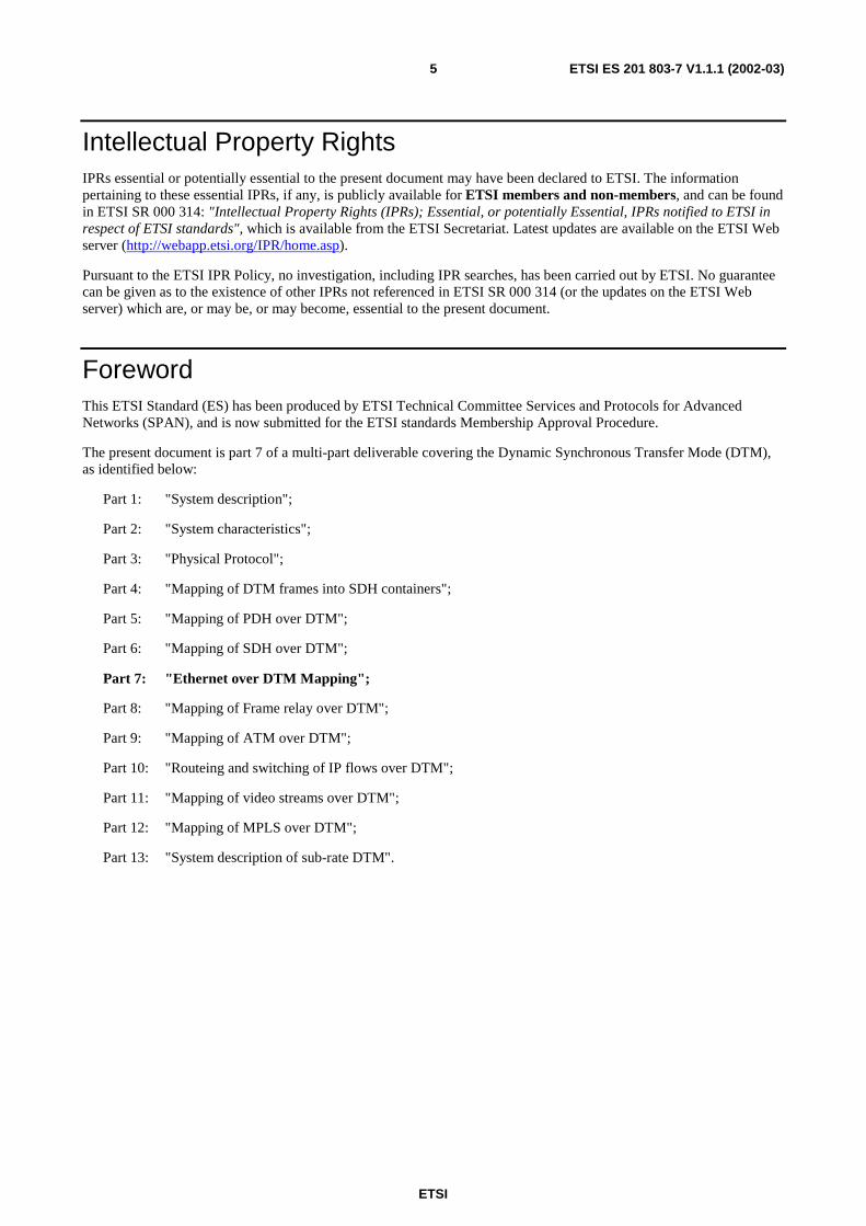
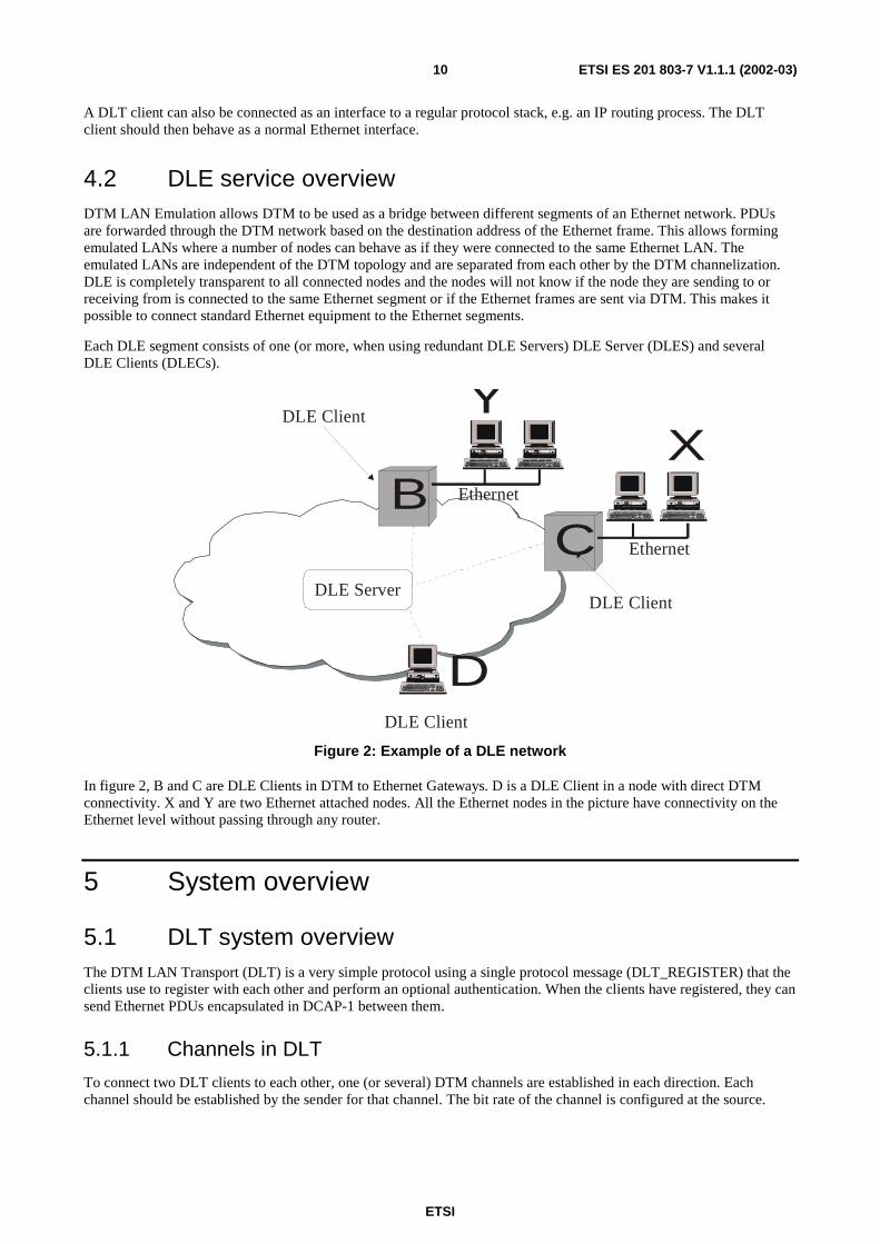
4.2 DLE service overview DTM LAN Emulation allows DTM to be used as a bridge between different segments of an Ethernet network. PDUs are forwarded through the DTM network based on the destination address of the Ethernet frame. This allows forming emulated LANs where a number of nodes can behave as if they were connected to the same Ethernet LAN. The emulated LANs are independent of the DTM topology and are separated from each other by the DTM channelization. DLE is completely transparent to all connected nodes and the nodes will not know if the node they are sending to or receiving from is connected to the same Ethernet segment or if the Ethernet frames are sent via DTM. This makes it possible to connect standard Ethernet equipment to the Ethernet segments.
Each DLE segment consists of one (or more, when using redundant DLE Servers) DLE Server (DLES) and several DLE Clients (DLECs).
DLE Server
Ethernet
Ethernet
DLE Client
DLE Client
DLE Client
B
YX
C
D
Figure 2: Example of a DLE network
In figure 2, B and C are DLE Clients in DTM to Ethernet Gateways. D is a DLE Client in a node with direct DTM connectivity. X and Y are two Ethernet attached nodes. All the Ethernet nodes in the picture have connectivity on the Ethernet level without passing through any router.
5 System overview
5.1 DLT system overview The DTM LAN Transport (DLT) is a very simple protocol using a single protocol message (DLT_REGISTER) that the clients use to register with each other and perform an optional authentication. When the clients have registered, they can send Ethernet PDUs encapsulated in DCAP-1 between them.
5.1.1 Channels in DLT
To connect two DLT clients to each other, one (or several) DTM channels are established in each direction. Each channel should be established by the sender for that channel. The bit rate of the channel is configured at the source.
ETSI
ETSI ES 201 803-7 V1.1.1 (2002-03)11
The Channel Multiplexing Identifier (CMI) in the DCAP-1 header is used to multiplex traffic on the channels. There are three different values defined for DLT. One is used for DLT control messages, one for Ethernet packets without a VLAN tag and one for Ethernet packets with a VLAN tag. The reason for having two different CMI values for Ethernet packets is that the packet format can then be optimized to make sure that the Ethernet data in the packet is always 64-bit aligned. The use of untagged transport format is limited to point-to-point Ethernet transport where the external interface does not use VLAN tagged format.
The Ethernet broadcast and multicast traffic is bound to a DTM channel (unicast or multicast). This implies that the broadcast or multicast traffic only reach the connected clients.
5.1.2 DLT client traffic forwarding
The DLT client should forward all PDUs (unicast, multicast and broadcast) that it receives from the logical Ethernet switch on its outgoing channel. All PDUs that it receives on the incoming DTM channel should be forwarded to the logical Ethernet switch.
All Ethernet PDUs forwarded between the DLT client and the logical Ethernet switch should have a VLAN associated with it. If no VLAN tag is present on the incoming Ethernet frame a default VLAN is attached to the frame.
5.2 DLE system overview A DLE segment connects a number of DLE Clients on Ethernet MAC layer, i.e. to the participating nodes it looks as if they are all connected to the same Ethernet LAN. In each DLE segment, there are one or several DLE Servers and one or several DLE Clients.
The DLE Server provides the following functions:
1) Address resolution between Ethernet and DTM egresses;
2) Forwards multicast and broadcast traffic to all DLE Clients;
3) Forwards unicast traffic from a DLEC when a direct channel to the destination DLEC has not been established. It also forwards packets for which an addresses resolution in the ingress DLEC has not been performed.
If more than one DLE Server is used in a DLE segment, they act as backups for each other. The DLE Server can be located anywhere in the DTM network as long as the node where the DLES is running has DTM connectivity to each of the other nodes.
The DLE Client forwards Ethernet frames to other DLE Clients in the DLE segment based on address information distributed from the DLE Server. The information is retrieved from the DLE Server by an address resolution process. If no relevant address resolution is present in the DLE Client or if there is not a direct channel established to the destination DLE Client, the Ethernet frames are forwarded to the DLE Server. As soon as the address is resolved and/or the channel is established, the Ethernet frames should be directly sent to the destination DLE Client.
The DLE Client can be an interface towards higher layer protocols, such as IP, or in an interworking function (bridging) between DTM and Ethernet.
A DLEC operates on the Ethernet MAC layer and forwards Ethernet frames between one or several Ethernet interfaces and other DLECs. Such DLEC can serve several Ethernet attached nodes simultaneously.
5.2.1 Channels in DLE
In a DLE segment with a single DLE Server, there are three different types of channel: Client-to-Client Channel (CCC), Client-to-Server Channel (CSC) and a Server-to-Clients Channel (SCC). Note that there is no channel from the DLE Server to a specific DLE Client. This means that all traffic from the DLES to a specific DLEC is sent on the broadcast SCC. Consequently, the DLECs filters messages received on the SCC that are not destined to the specific DLEC.
For redundant DLE Servers, there is also a Server-to-Server Channels (SSC). Each DLE Server in a DLE segment establishes one SSC to all other DLE Server in the segment. These channels are used to forward messages between the peer DLE Servers. The SSC is a DTM multicast channel.
ETSI
ETSI ES 201 803-7 V1.1.1 (2002-03)12
To establish a channel to a DLEC or a DLES, the DTM address, DSTI number of the client and a well-known DST value as specified in ES 201 803-2-2 (see Bibliography) is used.
Each channel used in a DLE segment is used only for a single DLE segment, thus DTM separates the traffic between the DLE segments.
5.2.2 Packet forwarding in the DLE Client
The DLE Client forwards all packets that it receives from the logical Ethernet switch to exactly one of its outgoing channels. The channel is selected based on the VLAN and destination MAC address of the packet. If the destination MAC address is a multicast MAC address, then the packet should be sent on the CSC.
If the destination MAC address is a unicast address, the VLAN and destination MAC address should be looked up in the address table of the DLE Client. This lookup can yield three different results:
1) There is an entry in the table with a reference to an open CCC. The packet should be sent on this CCC.
2) There is an entry in the table but there is no open CCC to that DLE Client. Send the packet on the CSC. A new channel should be opened to the DLE Client that the packet should have been sent to.
3) There is no entry in the table. Send the packet on the CSC. Initiate an address resolution request.
All Ethernet packets that the DLE Client receives on one of its incoming DTM channels should be sent to the logical Ethernet switch unless they have been received on the SCC and they have a source MAC address and VLAN that can be found in the Local MAC-Address table.
5.2.3 Address learning in the DLE Client
The DLE Client learns about MAC addresses that can be reached via the other DLE Clients connected to the same DLE segment by issuing Address Resolution Requests to the DLE Server and listening for Address Resolution Announcements sent from the DLE Server.
The DLE Client learns about MAC addresses that can be reached via other interfaces on the logical Ethernet switch that it is connected to either by explicitly asking the Ethernet switch for that information or by looking at the source MAC address of all packets delivered to the DLE Client from the logical Ethernet switch. This information is stored in a local MAC-Address table.
All address information should be associated with a VLAN, meaning that all address lookups and learning should be made on a combination of MAC address and VLAN.
5.2.4 Redundant DLE Servers
The redundant DLE Server mechanism makes it possible to run a number of DLE Servers for a single DLE segment without introducing inconsistency between the servers and allows for a simple implementation.
The basic idea is to have two or more DLE Servers that are equivalent. Protocol wise, it does not matter which DLE Server the clients connect to, or even whether all clients connect to the same server. In reality, it is probably easier to manage the network if all clients are configured in the same way, with one DLE Server as primary server and another as secondary. But in the case of partial connectivity losses in the network, it might happen that some clients connect to one DLE Server and some to another anyway.
All DLE Servers that serve the same DLE segment are connected to each other via Server to Server channels (SSCs). All traffic that a DLE Server receives from a DLE Client must be forwarded to the other DLE Servers using the SSCs.
Redundant DLE Servers are used to increase the availability of the server functionality and not to load balance between the servers. All DLE Servers process all Ethernet broadcasts in a DLE segment and all address resolution requests that can not be answered from the server's cache.
ETSI
ETSI ES 201 803-7 V1.1.1 (2002-03)13
5.3 VLAN Support VLANs are used to restrict which Ethernet data frame can be forwarded on a DLT-tunnel/DLE-segment. DLT and DLE Clients should have a set of allowed VLANs associated with it. This means that the DLT/DLE Client should only send packets with VLANs in this set out on DTM channels and only accept Ethernet data frames to receive belonging to a VLAN in this set from DTM channels. The DLT client may also send out Ethernet data frames without VLAN information (i.e. with VLAN=0) on DTM channels. These Ethernet data frames should be classified to belong to a default VLAN as configured in the receiving DLE/DLT client. All Ethernet data frames received by a DLT/DLE Client with a VLAN that is not in the set of allowed VLANs should be discarded.
VLAN information is encoded in the Ethernet data frame as described in IEEE 802.1Q [7], i.e. as four bytes after the MAC source address of the Ethernet data frame. Additionally, VLAN information is always transmitted before the Ethernet data frame (see clause 9). The extra VLAN information before the Ethernet data frame is added to optimize the transfer of untagged packets with VLAN information across a DLE/DLT channel. Instead of adding a VLAN tag per the IEEE 802.1Q [7] standard by modifying the Ethernet data frame, the sending client can simply add the VLAN information before the PDU and transmit it unmodified. The receiving client should interpret the Ethernet data frame as if it had been tagged with the VLAN tag supplied before the Ethernet data frame.
6 Service Interfaces
6.1 Transport view
EthernetBridge/Switch
function
Ethernet /DTMInterworking
function
DCAP-1
M_UNITDATA.request
DCAI
M_UNITDATA.indication
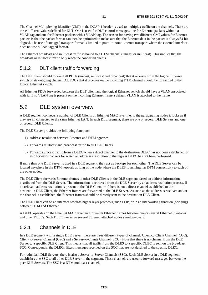
Figure 3: Transport view of Ethernet Interworking function
For the transport of Ethernet over DTM the Ethernet/DTM Interworking function utilizes the internal bridging interface for Ethernet bridges [6]. The internal bridging interface does not have a specific name but the primitives used are M_UNITDATA.request for Ethernet data towards the Ethernet/DTM Interworking function and M_UNITDATA.indication from the Ethernet/DTM Interworking function.
To transport the Ethernet packets over DTM, the Ethernet/DTM Interworking function uses the DCAI service interface of DCAP-1 (see ES 201 803-2-2, Bibliography).
NOTE: Within the Ethernet specification a procedural pseudo-code form is used form the formal modelling where as DTM otherwise uses the G.805/G.806 style formal modelling for transport. For the DTM management, a G.805/G.806 style TNRM will be used. The interface towards the MAC layer is done in the style of the Ethernet specification.
ETSI
ETSI ES 201 803-7 V1.1.1 (2002-03)14
6.2 Control view
Ethernet /DTMInterworking
function
ChannelManagement
module
DCP
DCCI
Networkmanagement
MIB
MIB
DCMI
Figure 4: Control view of Ethernet Interworking function
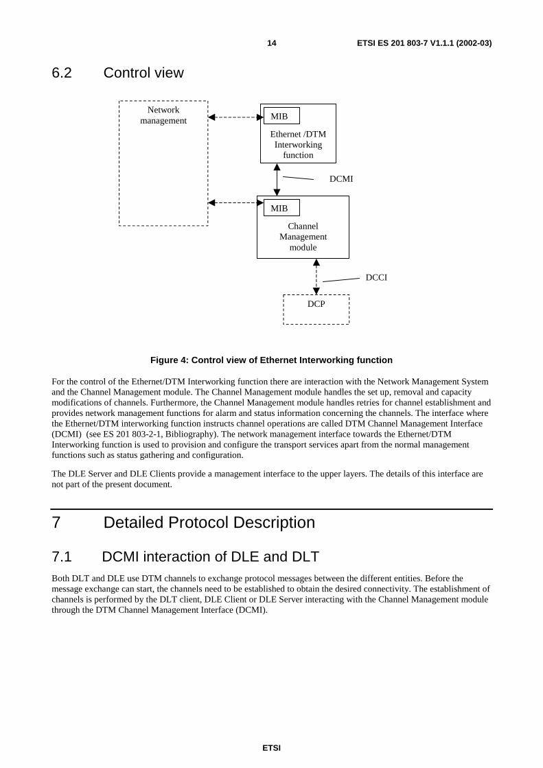
For the control of the Ethernet/DTM Interworking function there are interaction with the Network Management System and the Channel Management module. The Channel Management module handles the set up, removal and capacity modifications of channels. Furthermore, the Channel Management module handles retries for channel establishment and provides network management functions for alarm and status information concerning the channels. The interface where the Ethernet/DTM interworking function instructs channel operations are called DTM Channel Management Interface (DCMI) (see ES 201 803-2-1, Bibliography). The network management interface towards the Ethernet/DTM Interworking function is used to provision and configure the transport services apart from the normal management functions such as status gathering and configuration.
The DLE Server and DLE Clients provide a management interface to the upper layers. The details of this interface are not part of the present document.
7 Detailed Protocol Description
7.1 DCMI interaction of DLE and DLT Both DLT and DLE use DTM channels to exchange protocol messages between the different entities. Before the message exchange can start, the channels need to be established to obtain the desired connectivity. The establishment of channels is performed by the DLT client, DLE Client or DLE Server interacting with the Channel Management module through the DTM Channel Management Interface (DCMI).
ETSI
ETSI ES 201 803-7 V1.1.1 (2002-03)15
DCMI_CONNECTION_ESTABLISH
DLT/DLE DCMI
DCMI_ICHANNEL_RECEIVE
DCMI DLT/DLE
DCMI_ICHANNEL_ACCEPT
DCMI_OCHANNEL_ESTABLISHED
Source Destination
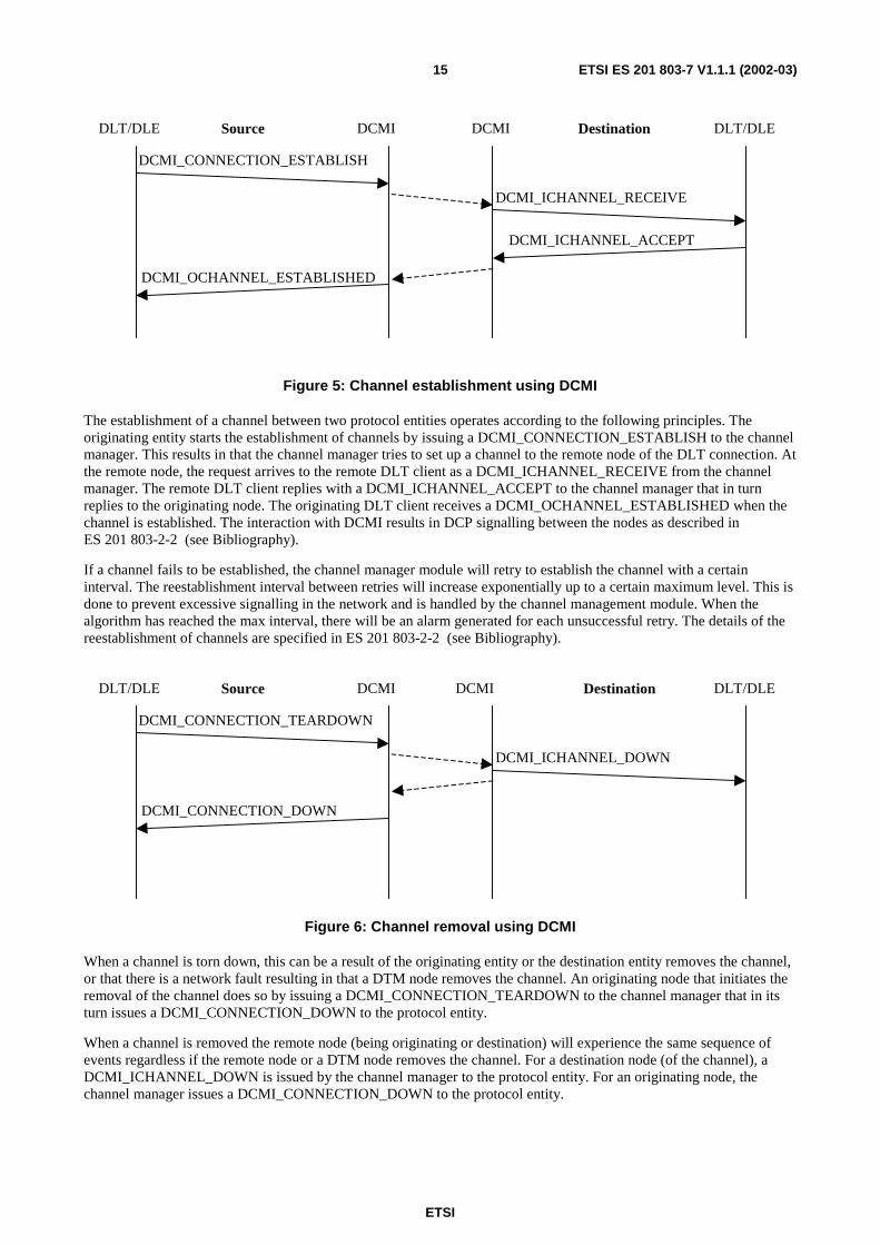
Figure 5: Channel establishment using DCMI
The establishment of a channel between two protocol entities operates according to the following principles. The originating entity starts the establishment of channels by issuing a DCMI_CONNECTION_ESTABLISH to the channel manager. This results in that the channel manager tries to set up a channel to the remote node of the DLT connection. At the remote node, the request arrives to the remote DLT client as a DCMI_ICHANNEL_RECEIVE from the channel manager. The remote DLT client replies with a DCMI_ICHANNEL_ACCEPT to the channel manager that in turn replies to the originating node. The originating DLT client receives a DCMI_OCHANNEL_ESTABLISHED when the channel is established. The interaction with DCMI results in DCP signalling between the nodes as described in ES 201 803-2-2 (see Bibliography).
If a channel fails to be established, the channel manager module will retry to establish the channel with a certain interval. The reestablishment interval between retries will increase exponentially up to a certain maximum level. This is done to prevent excessive signalling in the network and is handled by the channel management module. When the algorithm has reached the max interval, there will be an alarm generated for each unsuccessful retry. The details of the reestablishment of channels are specified in ES 201 803-2-2 (see Bibliography).
DCMI_CONNECTION_TEARDOWN
DLT/DLE DCMI
DCMI_ICHANNEL_DOWN
DCMI DLT/DLE
DCMI_CONNECTION_DOWN
Source Destination
Figure 6: Channel removal using DCMI
When a channel is torn down, this can be a result of the originating entity or the destination entity removes the channel, or that there is a network fault resulting in that a DTM node removes the channel. An originating node that initiates the removal of the channel does so by issuing a DCMI_CONNECTION_TEARDOWN to the channel manager that in its turn issues a DCMI_CONNECTION_DOWN to the protocol entity.
When a channel is removed the remote node (being originating or destination) will experience the same sequence of events regardless if the remote node or a DTM node removes the channel. For a destination node (of the channel), a DCMI_ICHANNEL_DOWN is issued by the channel manager to the protocol entity. For an originating node, the channel manager issues a DCMI_CONNECTION_DOWN to the protocol entity.
ETSI
ETSI ES 201 803-7 V1.1.1 (2002-03)16
7.2 DCAI interaction of DLE and DLT
SEND
RECEIVE
sender DCAI receiver
OK
OK
ADD_RECEIVER
OKDEL_RECEIVER
DCAI LT/DLEDLT/DLE
SEND
RECEIVEOK
DCAP-1
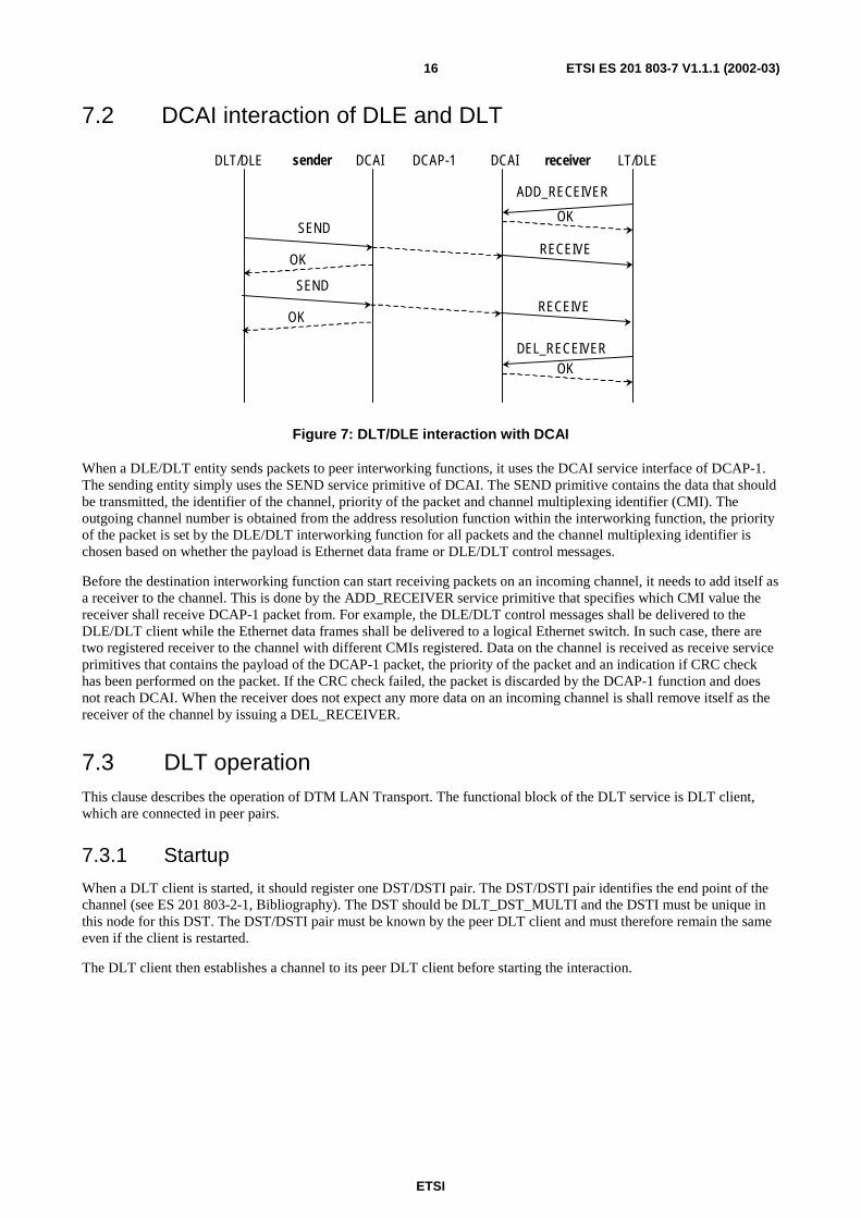
Figure 7: DLT/DLE interaction with DCAI
When a DLE/DLT entity sends packets to peer interworking functions, it uses the DCAI service interface of DCAP-1. The sending entity simply uses the SEND service primitive of DCAI. The SEND primitive contains the data that should be transmitted, the identifier of the channel, priority of the packet and channel multiplexing identifier (CMI). The outgoing channel number is obtained from the address resolution function within the interworking function, the priority of the packet is set by the DLE/DLT interworking function for all packets and the channel multiplexing identifier is chosen based on whether the payload is Ethernet data frame or DLE/DLT control messages.
Before the destination interworking function can start receiving packets on an incoming channel, it needs to add itself as a receiver to the channel. This is done by the ADD_RECEIVER service primitive that specifies which CMI value the receiver shall receive DCAP-1 packet from. For example, the DLE/DLT control messages shall be delivered to the DLE/DLT client while the Ethernet data frames shall be delivered to a logical Ethernet switch. In such case, there are two registered receiver to the channel with different CMIs registered. Data on the channel is received as receive service primitives that contains the payload of the DCAP-1 packet, the priority of the packet and an indication if CRC check has been performed on the packet. If the CRC check failed, the packet is discarded by the DCAP-1 function and does not reach DCAI. When the receiver does not expect any more data on an incoming channel is shall remove itself as the receiver of the channel by issuing a DEL_RECEIVER.
7.3 DLT operation This clause describes the operation of DTM LAN Transport. The functional block of the DLT service is DLT client, which are connected in peer pairs.
7.3.1 Startup
When a DLT client is started, it should register one DST/DSTI pair. The DST/DSTI pair identifies the end point of the channel (see ES 201 803-2-1, Bibliography). The DST should be DLT_DST_MULTI and the DSTI must be unique in this node for this DST. The DST/DSTI pair must be known by the peer DLT client and must therefore remain the same even if the client is restarted.
The DLT client then establishes a channel to its peer DLT client before starting the interaction.
ETSI
ETSI ES 201 803-7 V1.1.1 (2002-03)17
DLT Client DLT Client
DLT REGISTER
Ethernet data
Ethernet data
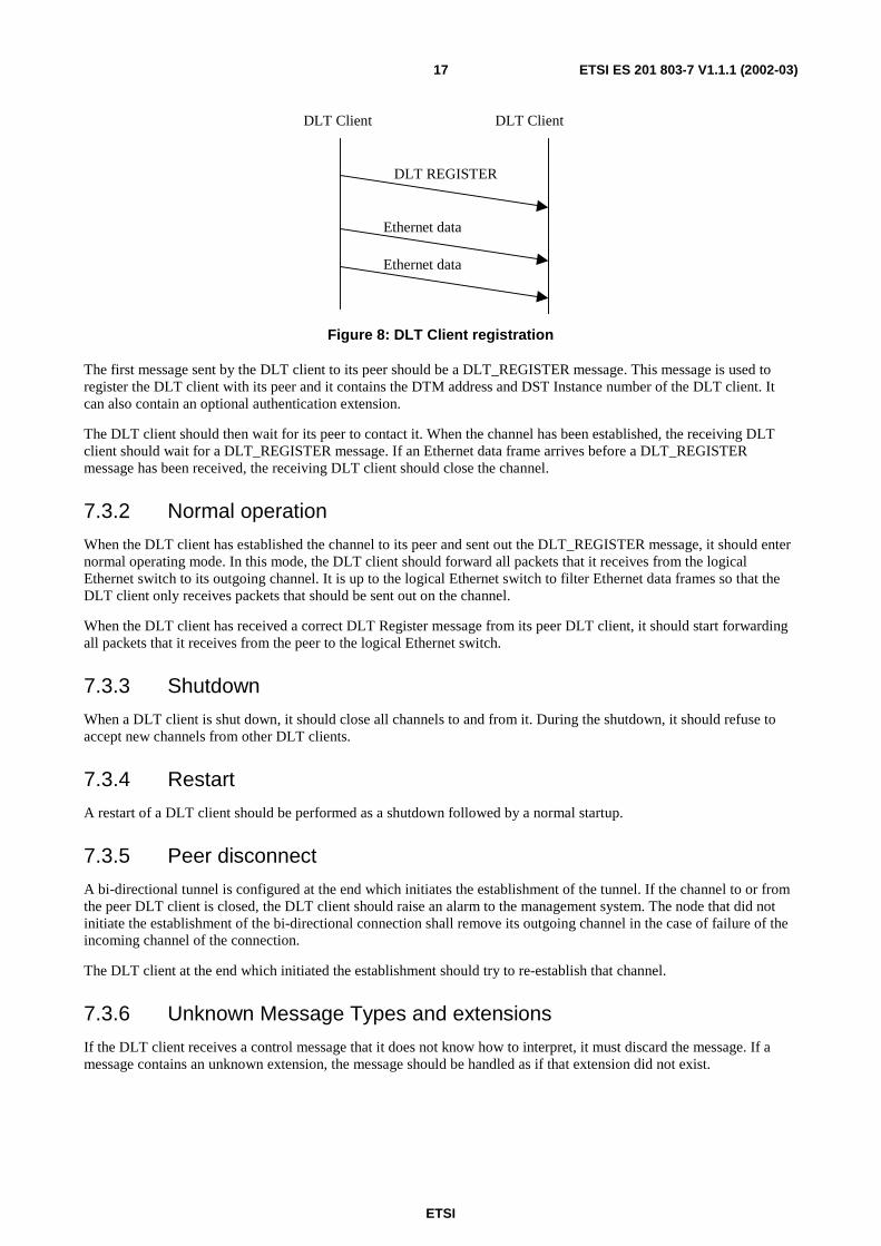
Figure 8: DLT Client registration
The first message sent by the DLT client to its peer should be a DLT_REGISTER message. This message is used to register the DLT client with its peer and it contains the DTM address and DST Instance number of the DLT client. It can also contain an optional authentication extension.
The DLT client should then wait for its peer to contact it. When the channel has been established, the receiving DLT client should wait for a DLT_REGISTER message. If an Ethernet data frame arrives before a DLT_REGISTER message has been received, the receiving DLT client should close the channel.
7.3.2 Normal operation
When the DLT client has established the channel to its peer and sent out the DLT_REGISTER message, it should enter normal operating mode. In this mode, the DLT client should forward all packets that it receives from the logical Ethernet switch to its outgoing channel. It is up to the logical Ethernet switch to filter Ethernet data frames so that the DLT client only receives packets that should be sent out on the channel.
When the DLT client has received a correct DLT Register message from its peer DLT client, it should start forwarding all packets that it receives from the peer to the logical Ethernet switch.
7.3.3 Shutdown
When a DLT client is shut down, it should close all channels to and from it. During the shutdown, it should refuse to accept new channels from other DLT clients.
7.3.4 Restart
A restart of a DLT client should be performed as a shutdown followed by a normal startup.
7.3.5 Peer disconnect
A bi-directional tunnel is configured at the end which initiates the establishment of the tunnel. If the channel to or from the peer DLT client is closed, the DLT client should raise an alarm to the management system. The node that did not initiate the establishment of the bi-directional connection shall remove its outgoing channel in the case of failure of the incoming channel of the connection.
The DLT client at the end which initiated the establishment should try to re-establish that channel.
7.3.6 Unknown Message Types and extensions
If the DLT client receives a control message that it does not know how to interpret, it must discard the message. If a message contains an unknown extension, the message should be handled as if that extension did not exist.
ETSI
ETSI ES 201 803-7 V1.1.1 (2002-03)18
7.4 DLE operation This clause describes the operation of the DLE Server and DLE Client, and how these function interact protocol wise.
7.4.1 Server startup
When the DLE Server is started, it must have an empty address resolution cache. It starts by registering two DST/DSTI pairs (one for communication with DLE Clients and one for communication with peer DLE Servers) as configured. The DSTs should be:
• DLE_DST_MULTI
• DLE_DST_S_MULTI
The DSTI must be unique within the node for the specific DSTs. Note that the same DSTI must be used for both DSTs. This DSTI must not be changed, since it is configured in the DLE Clients and the peer DLE Servers that should connect to this DLE Server.
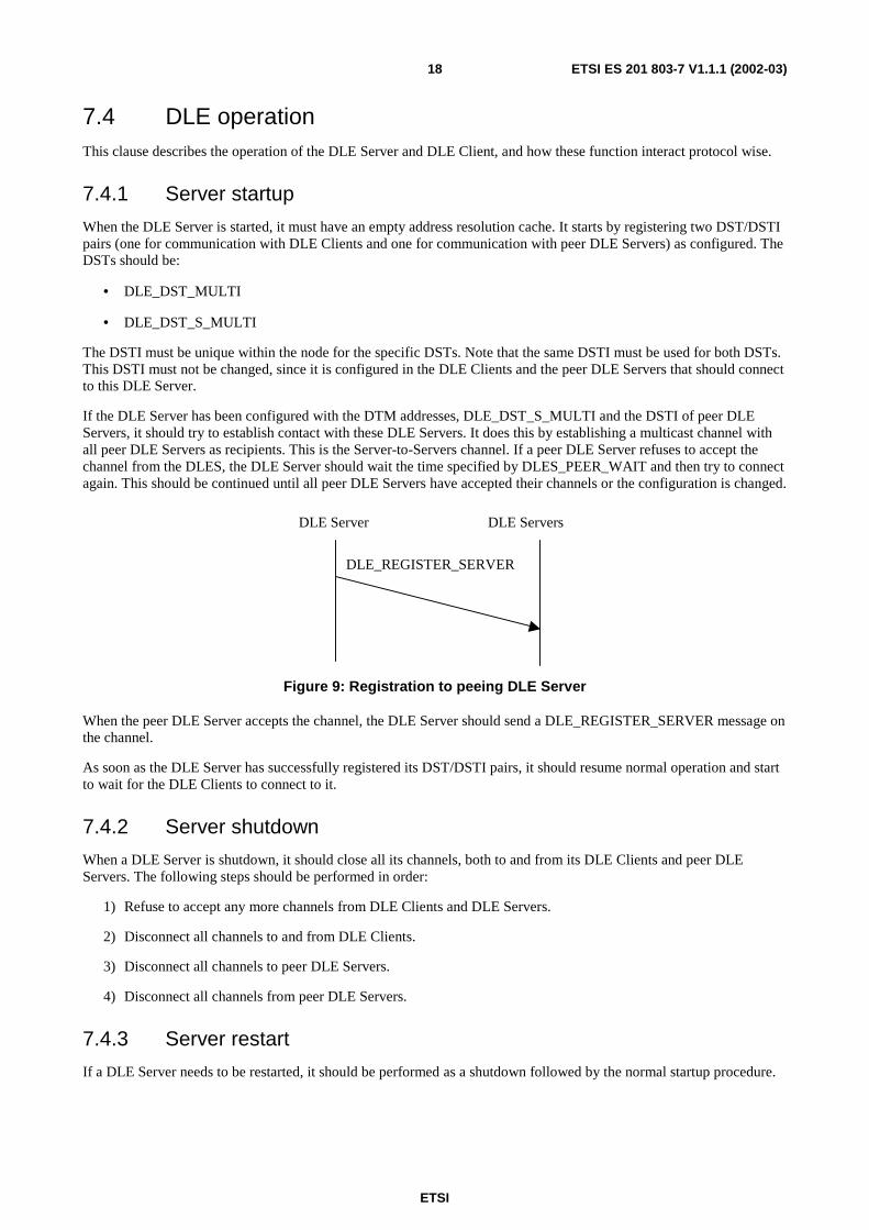
If the DLE Server has been configured with the DTM addresses, DLE_DST_S_MULTI and the DSTI of peer DLE Servers, it should try to establish contact with these DLE Servers. It does this by establishing a multicast channel with all peer DLE Servers as recipients. This is the Server-to-Servers channel. If a peer DLE Server refuses to accept the channel from the DLES, the DLE Server should wait the time specified by DLES_PEER_WAIT and then try to connect again. This should be continued until all peer DLE Servers have accepted their channels or the configuration is changed.
DLE Server DLE Servers
DLE_REGISTER_SERVER
Figure 9: Registration to peeing DLE Server
When the peer DLE Server accepts the channel, the DLE Server should send a DLE_REGISTER_SERVER message on the channel.
As soon as the DLE Server has successfully registered its DST/DSTI pairs, it should resume normal operation and start to wait for the DLE Clients to connect to it.
7.4.2 Server shutdown
When a DLE Server is shutdown, it should close all its channels, both to and from its DLE Clients and peer DLE Servers. The following steps should be performed in order:
1) Refuse to accept any more channels from DLE Clients and DLE Servers.
2) Disconnect all channels to and from DLE Clients.
3) Disconnect all channels to peer DLE Servers.
4) Disconnect all channels from peer DLE Servers.
7.4.3 Server restart
If a DLE Server needs to be restarted, it should be performed as a shutdown followed by the normal startup procedure.
ETSI
ETSI ES 201 803-7 V1.1.1 (2002-03)19
7.4.4 New server connected to the DLE segment
When the DLE Server receives a channel on a Server-to-Server DST, it must accept the channel and allow the connecting server to try to register. Before accepting any other messages than DLE_SERVER_REGISTER messages from the other DLE Server, a correct DLE_SERVER_REGISTER message must be received. If an incorrect DLE_SERVER_REGISTER message is received, the receiving DLE Server must remove the channel. If no DLE_REGISTER_SERVER message is received within the time specified by DLES_REGISTER_MIN_WAIT, the receiving DLE Server must terminate the channel.
The received DLE_SERVER_REGISTER message should be checked against the set of configured peer servers. If the DLE Server that is trying to register is not in the set of configured peers, the channel from the connecting DLE Server should be closed by the receiving DLE Server.
If a DLE_SERVER_REGISTER message is received on an SSC that has already been accepted, the message should be ignored.
7.4.5 Server disconnection
7.4.5.1 Removal of server to server channel
If a DLE Server (A) notices that the SSC from another DLE Server (B) has been closed, A should consider B as disconnected from the DLE segment and close the channel from A to B as well. All address resolution entries learned from this peer must be flushed from the cache. This can be implemented as a flush of the entire address resolution cache.
After a peer DLE Server has been disconnected, the DLE Server should try to re-establish contact with the peer as shown in clause 7.3.1, given that the DLE Server is still configured as being a peer.
If A notices that its channel to B has been closed, i.e. B is no longer a recipient for A's multicast SSC, A should try to add B as a recipient for the SSC again. When B has been added as recipient, A should send a DLE_SERVER_REGISTER message on its SSC.
7.4.5.2 Server removal of channel between server and client
If the DLE Client detects that either the CSC or the SCC has been closed, the DLE Client should close all remaining channels to and from the DLE Server and reinitiate the connection procedure with the DLE Server as described in clause 7.3.1. The DLE Client should however keep the same DSTI number as before if possible.
During the period when no connection with a DLE Server is established, the DLE Client is allowed to keep channels to other DLE Clients as long as it has valid address resolution information for these destinations. When the address resolution expires, the channels must however be closed if the DLE Client has been unable to acquire new address resolution information.
7.4.6 Client start up
DLEC DLES
DLE_REGISTER
DLE_REGISTER_RESPONSE
DLEC
DLE_REGISTER_RESPONSE
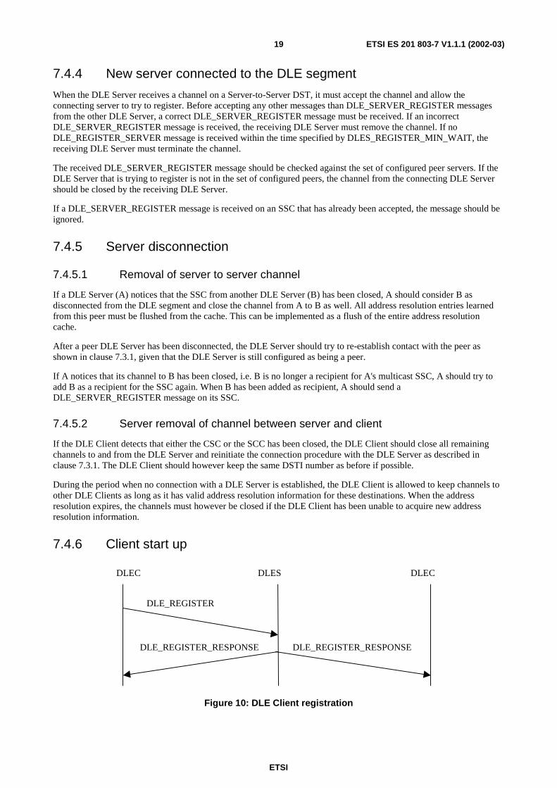
Figure 10: DLE Client registration
ETSI
ETSI ES 201 803-7 V1.1.1 (2002-03)20
When a DLEC is started, it should register one DST/DSTI pair. The DST should be DLE_DST_MULTI and the DSTI must be unique in the node for this DST.
The DLEC then establishes a channel to the DLES. This is the Client-to-Server Channel (CSC) of the DLEC. The DLEC may be configured with the addresses of a number (N) of DLE Servers. If this is the case, the DLEC should try to connect to them in the configured order until one of the contacted DLE Servers accepts the channel and completes the registration process as described below. The DLEC tries to connect to the N different DLES in the configured order following a round-robin order.
When a new DLE Client tries to establish a channel to the DLES, the DLES must accept the channel if it has enough resources to do so. It must however discard all Ethernet frames and DLE messages other than DLE_REGISTER messages until a correct DLE_REGISTER message has been received.
The first message sent by the DLEC to the DLES on the CSC should be a DLE_REGISTER message. This message is used to register the DLEC with the DLES and it contains the DTM address and DST Instance number of the DLEC.
Upon reception of a correct DLE_REGISTER message, the DLES must add the DLEC specified in the message to the recipients of the Server-to-Clients Channel (SCC), i.e., a new branch of the SCC should be added to the newly registered DLE Client on the DTM address and DSTI number provided in the DLE_REGISTER message. The DLE Client waits for the channel to be established. Once the new receiver has been added to the SCC, a DLE_REGISTER_RESPONSE message should be sent on the SCC. After the DLE Client has received the DLE_REGISTER_RESPONSE, it can start normal operating.
If more than one DLE_REGISTER message is received from one DLEC, the action depends on whether the new message is identical to the old message or not. If they are identical, resend the DLE_REGISTER_RESPONSE message. If they are not identical, the DLEC must be disconnected and all information about the DLEC (including address resolution entries in the cache of the DLES) must be cleared. The DLEC can then connect again and re-register.
A DLEC is not allowed to establish more than one CSC to the same DLES. It is however permitted for two DLECs to share the same DTM address but use different DST Instances.
If the DLES does not establish a channel to the DLEC or if the DLE_REGISTER_RESPONSE message is not received within DLEC_REGISTER_RETRY_TIMEOUT milliseconds, the DLEC is allowed to resend the DLE_REGISTER message. The DLE_REGISTER message can be retransmitted DLEC_REGISTER_RETRIES times. If the DLE Server still has not responded properly, the DLEC must disconnect the channel and continue with the next DLE Server in turn as specified above.
7.4.7 Client restart
If a DLE Client needs to be restarted, it should first close all channels to and from the DLE Server. It may optionally close channels to and from other DLE Clients. When the DLE Client has been restarted, it should try to register with a DLE Server again as shown in clause 7.3.1.
If a DLE Client is moved from one DLE segment to another, it must close all channels to and from other DLE Clients before connecting to the new DLE Server.
7.4.8 Client disconnect
When a DLE Client is shut down, it should close all channels to and from it, starting with the channels to and from the DLE Server. During the shutdown, it should refuse to accept new channels from other DLE Clients.
The DLE Server should completely remove the DLE Client if a DLE Client disconnects, either by detaching from the SCC or closing the CSC. This means that the DLEC should be detached from the SCC, its CSC should be closed, and all address resolution cache entries in the DLES concerning the DLEC should be removed from the DLES. The DLE Server should also send a DLE_CLIENT_DISCONNECTED message to all peer DLE Servers.
When a DLE Server receives a DLE_CLIENT_DISCONNECTED message from a peer DLE Server, it must remove all address resolution entries pointing to that client from its cache.
ETSI
ETSI ES 201 803-7 V1.1.1 (2002-03)21
7.4.9 Address resolution
DLEC DLES
DLE_AR_REQUEST
DLEC(s)
DLE_AR_REQUEST
DLE_AR_ANNOUNCE
DLE_AR_ANNOUNCE DLE_AR_ANNOUNCE
DLE_AR_REQUEST
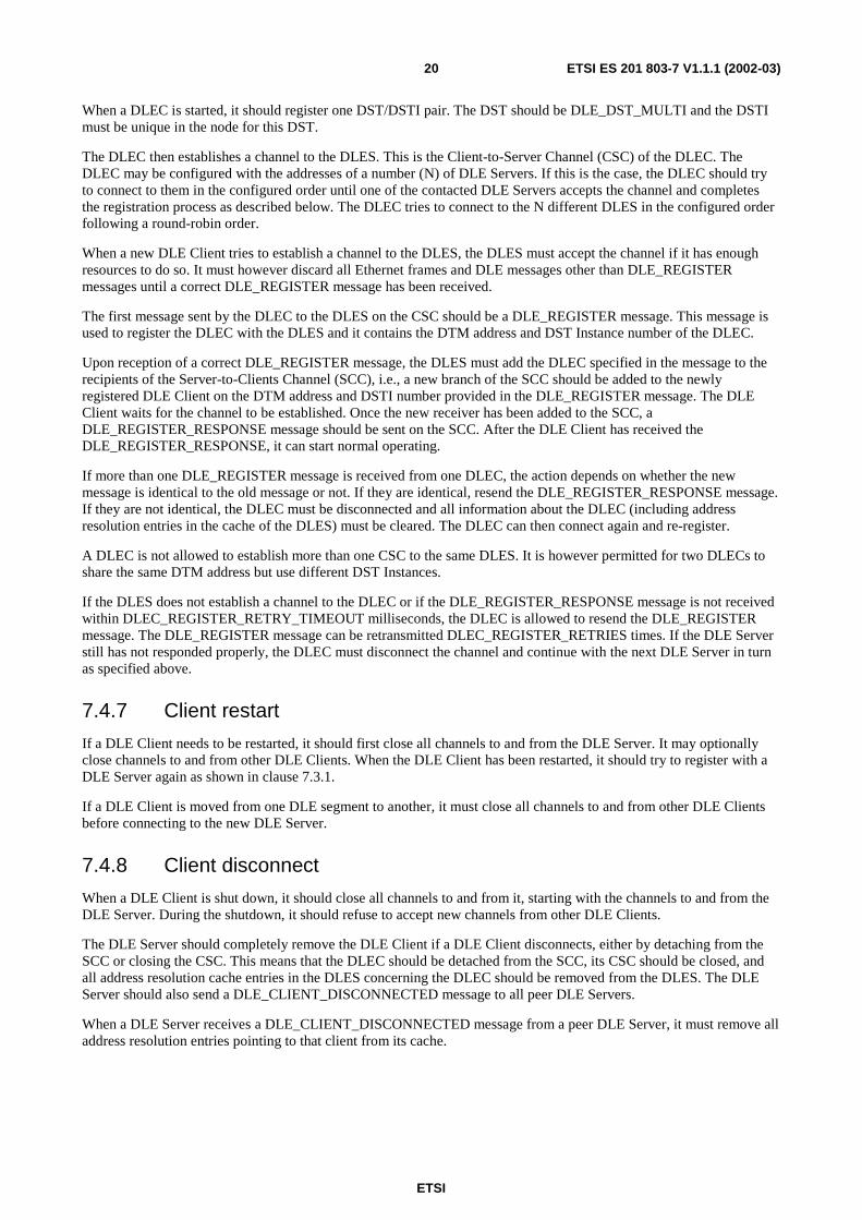
Figure 11: Address resolution
A DLEC initiates an address resolution procedure by sending a DLE_AR_REQUEST message to the DLES.
When the DLES receives a DLE_AR_REQUEST message it should first examine its own cache to see whether it already has a cached entry for this request. If so, the DLES MAY generate a DLE_AR_ANNOUNCE message. The lifetime of the generated announcement should be the lifetime of the original announcement, minus the time that it has been in the cache. If this lifetime is larger than DLES_ANNOUNCE_LIFETIME, then DLES_ANNOUNCE_LIFETIME should be used instead. The announcement should be sent on the broadcast SCC if the request arrived on a CCC, or if the request came from a peer DLE Server, on the SSC to all peers.
If the DLES has no cached entry for the request, a DLE_AR_REQUEST should be sent out on the SCC to query all the DLECs and to the peer DLE Servers as well if the request did not come from a peer.
If the DLE_AR_REQUEST asks for an address that does not belong to the VLANs that are valid for this DLE segment, the request should be discarded. DLE Clients must keep track of the Ethernet destinations they serve.
When the DLE Client receives a DLE_AR_REQUEST asking for an Ethernet destination that this DLE Client serves, the DLE Client must generate an address resolution announcement for that Ethernet destination and send it to the DLE Server.
The DLEC is responsible for retransmitting its DLE_AR_REQUEST message if no corresponding announcement is received within the time specified by DLEC_AR_REQUEST_TIMEOUT. It may retransmit its request until an announcement is received as long as the DLEC still receives traffic to that destination.
When the DLES receives a DLE_AR_ANNOUNCEMENT, it must be forwarded to all DLECs via the SCC if a DLEC has asked for the announcement with an Address Resolution Request and has not received a response yet. The DLES MAY forward all DLE_AR_ANNOUNCEMENTs to all DLECs via the SCC. If the announcement arrived on a CSC, it should be sent to all peer DLE Servers as well.
If the DLE_AR_ANNOUNCEMENT announces an address that does not belong to the set of allowed VLANs, it must be discarded.
If a DLEC X detects a destination on a locally attached LAN, that according to the address cache in X should be connected to another DLEC, then X must immediately send a DLE_AR_ANNOUNCE message to the DLES and announce that the destination is now served by DLEC X. This will typically happen when a destination is moved from one DLEC to another and the DLE_AR_ANNOUNCE message will then speed up the detection of this move by all other nodes.
ETSI
ETSI ES 201 803-7 V1.1.1 (2002-03)22
7.4.9.1 Forwarding Ethernet frames with unknown destination
Preferably, the Ethernet traffic in a DLE segment should be transported on CCCs.
When the DLEC wants to transmit an Ethernet frame for which it has no CCC, it must send the frame to the DLES on the CSC or buffer it until a CCC has been established.
The CCC is established in two steps. Firstly, an address resolution record for the destination has to be found. Secondly, a DTM channel has to be established if a CCC to the DLEC serving that Ethernet destination does not already exist. If a CCC already exists, this can be used instead of establishing a new CCC. If the node fails to establish the channel, the channel manager will retry to establish the channel as described in the previous clause.
During the time traffic to an Ethernet destination is sent on a CCC, the DLEC must always have up-to-date address resolution information. If the address resolution should expire, the DLEC must stop using the CCC for that Ethernet destination and start sending packets to that Ethernet destination via the DLES until it receives a new address resolution announcement. To avoid this, it must refresh its address resolution information before it expires and it must listen for address resolution announcements concerning the Ethernet destinations that it sends packets to. If the DLEC receives a new address resolution announcement that differs from the old information, the DLEC MUST use the new address resolution information instead of the old one.
7.4.9.2 Fast address announce
A DLEC is allowed to send out DLE_AR_ANNOUNCE messages as soon as it detects a new destination instead of waiting for another DLEC to send a DLE_AR_REQUEST message for that destination. This will lead to faster establishment of CCCs at the expense of slightly more DLE_AR_ANNOUNCE messages and more information in the address caches of the DLECs under some circumstances. A DLEC must however always respond to DLE_AR_REQUEST messages even if it has already sent out a DLE_AR_ANNOUNCE message for that destination.
7.4.10 Flush mechanism
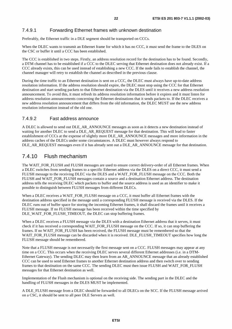
The WAIT_FOR_FLUSH and FLUSH messages are used to ensure correct delivery-order of all Ethernet frames. When a DLEC switches from sending frames to a specific Ethernet address via the DLES on a direct CCC, it must send a FLUSH message to the receiving DLEC via the DLES and a WAIT_FOR_FLUSH message on the CCC. Both the FLUSH and WAIT_FOR_FLUSH messages contain a source and a destination Ethernet address. The destination address tells the receiving DLEC which packets to buffer and the source address is used as an identifier to make it possible to distinguish between FLUSH messages from different DLECs.
When a DLEC receives a WAIT_FOR_FLUSH message on a CCC, it must buffer all Ethernet frames with the destination address specified in the message until a corresponding FLUSH message is received via the DLES. If the DLEC runs out of buffer space for storing the incoming Ethernet frames, it shall discard the frames until it receives a FLUSH message. If no FLUSH message has been received within the time specified by DLE_WAIT_FOR_FLUSH_TIMEOUT, the DLEC can stop buffering frames.
When a DLEC receives a FLUSH message via the DLES with a destination Ethernet address that it serves, it must check if it has received a corresponding WAIT_FOR_FLUSH message on the CCC. If so, it can stop buffering the frames. If no WAIT_FOR_FLUSH has been received, the FLUSH message must be remembered so that the WAIT_FOR_FLUSH message can be discarded when it is received. DLE_FLUSH_TIMEOUT specifies how long the FLUSH message should be remembered.
Note that a FLUSH message is not necessarily the first message sent on a CCC. FLUSH messages may appear at any time on a CCC. This occurs when the receiving DLEC serves several different Ethernet addresses (i.e. in a DTM-Ethernet Gateway). The sending DLEC may then learn from an AR_ANNOUNCE message that an already established CCC can be used to send Ethernet frames to another Ethernet destination address and then switch over to sending frames to that destination on the same CCC. The sending DLEC must then issue FLUSH and WAIT_FOR_FLUSH messages for that Ethernet destination as well.
Implementation of the Flush mechanism is optional on the receiving side. The sending part in the DLEC and the handling of FLUSH messages in the DLES MUST be implemented.
A DLE_FLUSH message from a DLEC should be forwarded to all DLECs on the SCC. If the FLUSH message arrived on a CSC, it should be sent to all peer DLE Servers as well.
ETSI
ETSI ES 201 803-7 V1.1.1 (2002-03)23
DLEC 2 DLEC 1
DLE_WAIT_FOR_FLUSH
DLES DLEC 2
Ethernet frame
Ethernet frame
DLE_FLUSH
Ethernet frame
Ethernet frame DLE_FLUSHDLE_FLUSH
Figure 12: Flush mechanism example
DLEC 1 is sending Ethernet data frames to DLEC 2 via the DLES (arrows in the right direction). Before it switches to sending on a direct CCC, it sends a DLE_FLUSH message to DLEC 2 via the DLES. As the first message on the newly established CCC, DLEC 1 sends a DLE_WAIT_FOR_FLUSH message to DLEC 2. After sending the DLE_WAIT_FOR_FLUSH message, DLEC 1 can start sending data frames on the CCC immediately.
When DLEC 2 receives the DLE_WAIT_FOR_FLUSH message on the CCC, it knows that to prevent frame reordering, it must buffer frames arriving on the CCC with the destination Ethernet address specified in the DLE_WAIT_FOR_FLUSH message and first process all frames arriving from the DLES, until a DLE_FLUSH message with the same source and destination Ethernet addresses arrives from the DLES.
7.4.11 Normal server operation
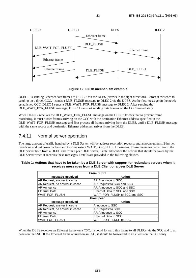
The large amount of traffic handled by a DLE Server will be address resolution requests and announcements, Ethernet broadcast and unknown packets and to some extent WAIT_FOR_FLUSH messages. These messages can arrive to the DLE Server both from a DLEC and from a peer DLE Server. Table 1describes the actions that should be taken by the DLE Server when it receives these messages. Details are provided in the following clauses.
Table 1: Actions that have to be taken by a DLE Server with support for redundant servers when it receives messages from a DLE Client or a peer DLE Server
From DLEC Message Received Action
AR Request, answer in cache AR Announce to SCC AR Request, no answer in cache AR Request to SCC and SSC AR Announce AR Announce to SCC and SSC Ethernet Data Ethernet Data to SCC and SSC WAIT_FOR_FLUSH WAIT_FOR_FLUSH to SCC and SSC
From peer Message Received Action
AR Request, answer in cache Announce to SSC AR Request, no answer in cache AR Request to SCC AR Announce AR Announce to SCC Ethernet Data Ethernet Data to SCC WAIT_FOR_FLUSH WAIT_FOR_FLUSH to SCC
When the DLES receives an Ethernet frame on a CSC, it should forward this frame to all DLECs via the SCC and to all peers on the SSC. If the Ethernet frame arrived on an SSC, it should be forwarded to all clients on the SCC only.
ETSI
ETSI ES 201 803-7 V1.1.1 (2002-03)24
7.4.12 SCC Filtering
DLECs must always store the source MAC address of all Ethernet frames that it sends to the DLES in a local address cache. If the DLECs should fail to store a source MAC address in the local cache (cache full for example), then the Ethernet frame must not be sent to the DLES and the DLEC must discard the frame. The failure of discarding packets for which the source MAC address has not been cached will lead to the inability to properly filter packets received from the SCC and the packets will be reinserted into the originating LAN. External Ethernet switches will then get corrupt address information and connectivity will be lost between hosts until the faulty entry has been timed out or learnt correctly again.
7.4.13 Unknown message types
If the DLEC receives a message that it does not know how to interpret, it must discard the message. If a message contains an unknown extension, the message should be handled as if that extension did not exist.
If the DLES receives a message that it does not know how to interpret, it must forward the message on the SCC and the SSC. If a message contains an unknown extension, the message should be processed as if the extension did not exist. When forwarding messages from a DLEC to all DLECs and/or peers, even unknown extensions should be forwarded.
8 Messages
8.1 General Message Format All DLE and DLT control messages should be sent as DCAP-1 packets with a special value in the CMI field of the DCAP-1 header to be able to distinguish them from Ethernet packets. A DCAP-1 trailer with a packet checksum shall be appended to the packet.
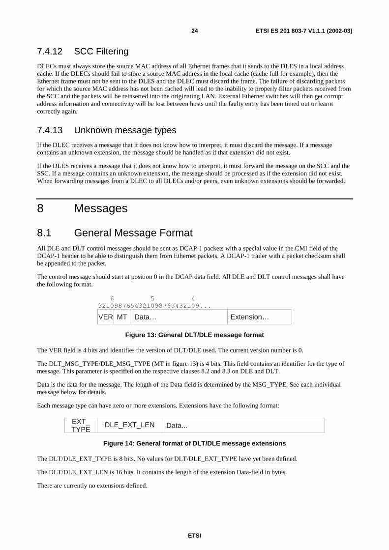
The control message should start at position 0 in the DCAP data field. All DLE and DLT control messages shall have the following format.
VER MT Data… Extension…
Figure 13: General DLT/DLE message format
The VER field is 4 bits and identifies the version of DLT/DLE used. The current version number is 0.
The DLT_MSG_TYPE/DLE_MSG_TYPE (MT in figure 13) is 4 bits. This field contains an identifier for the type of message. This parameter is specified on the respective clauses 8.2 and 8.3 on DLE and DLT.
Data is the data for the message. The length of the Data field is determined by the MSG_TYPE. See each individual message below for details.
Each message type can have zero or more extensions. Extensions have the following format:
EXT_TYPE
DLE_EXT_LEN Data...
Figure 14: General format of DLT/DLE message extensions
The DLT/DLE_EXT_TYPE is 8 bits. No values for DLT/DLE_EXT_TYPE have yet been defined.
The DLT/DLE_EXT_LEN is 16 bits. It contains the length of the extension Data-field in bytes.
There are currently no extensions defined.
ETSI
ETSI ES 201 803-7 V1.1.1 (2002-03)25
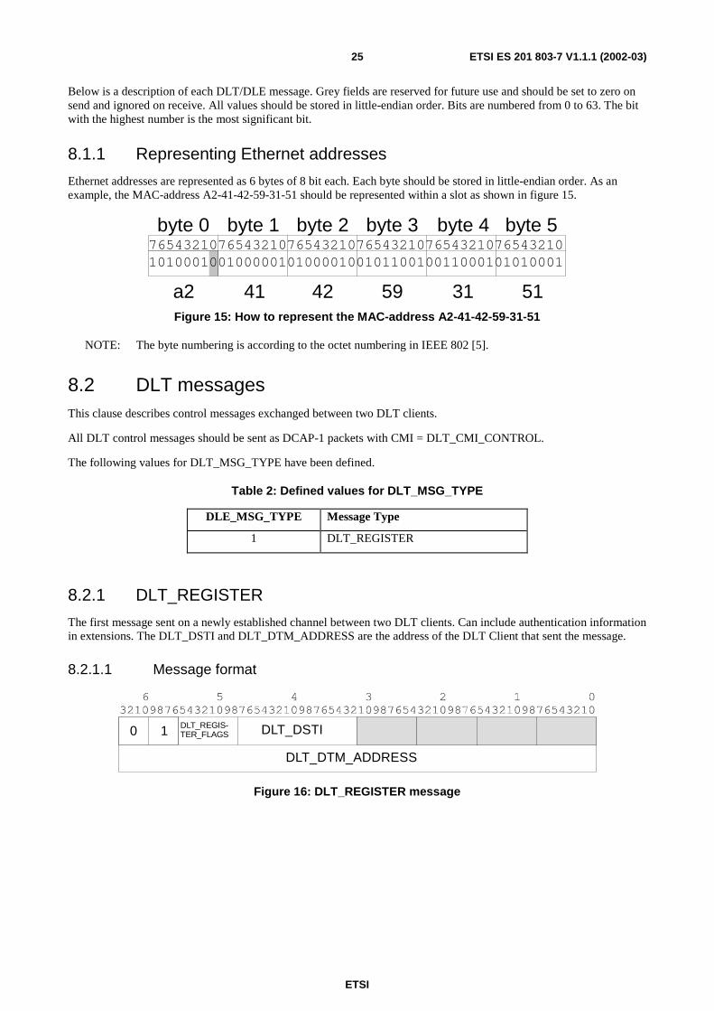
Below is a description of each DLT/DLE message. Grey fields are reserved for future use and should be set to zero on send and ignored on receive. All values should be stored in little-endian order. Bits are numbered from 0 to 63. The bit with the highest number is the most significant bit.
8.1.1 Representing Ethernet addresses
Ethernet addresses are represented as 6 bytes of 8 bit each. Each byte should be stored in little-endian order. As an example, the MAC-address A2-41-42-59-31-51 should be represented within a slot as shown in figure 15.
765432107654321076543210765432107654321076543210101000100100000101000010010110010011000101010001
a2 4241 59 31 51
byte 0 byte 1 byte 2 byte 3 byte 5byte 4
Figure 15: How to represent the MAC-address A2-41-42-59-31-51
NOTE: The byte numbering is according to the octet numbering in IEEE 802 [5].
8.2 DLT messages This clause describes control messages exchanged between two DLT clients.
All DLT control messages should be sent as DCAP-1 packets with CMI = DLT_CMI_CONTROL.
The following values for DLT_MSG_TYPE have been defined.
Table 2: Defined values for DLT_MSG_TYPE
DLE_MSG_TYPE Message Type
1 DLT_REGISTER
8.2.1 DLT_REGISTER
The first message sent on a newly established channel between two DLT clients. Can include authentication information in extensions. The DLT_DSTI and DLT_DTM_ADDRESS are the address of the DLT Client that sent the message.
8.2.1.1 Message format
DLT_REGIS-TER_FLAGS DLT_DSTI
DLT_DTM_ADDRESS
0 1
Figure 16: DLT_REGISTER message
ETSI
ETSI ES 201 803-7 V1.1.1 (2002-03)26
The DLT_REGISTER_FLAGS is an 8-bit field in the following format.
01234567
U U U U U U U U
Figure 17: DLT_REGISTER_FLAGS-field
U Unused. Set to zero when sending and ignore when receiving.
8.3 DLE messages This clause describes the different control messages exchanged between a DLEC and a DLES or between two DLECs or DLESs.
The following values for DLE_MSG_TYPE have been defined.
Table 3: Defined values for DLE_MSG_TYPE
DLE_MSG_TYPE Message Type 1 DLE_REGISTER 2 DLE_REGISTER_RESPONSE 3 DLE_AR_REQUEST 4 DLE_AR_ANNOUNCE 5 DLE_WAIT_FOR_FLUSH 6 DLE_FLUSH 7 DLE_AUTHENTICATE 8 DLE_SERVER_REGISTER 9 DLE_CLIENT_DISCONNECTED
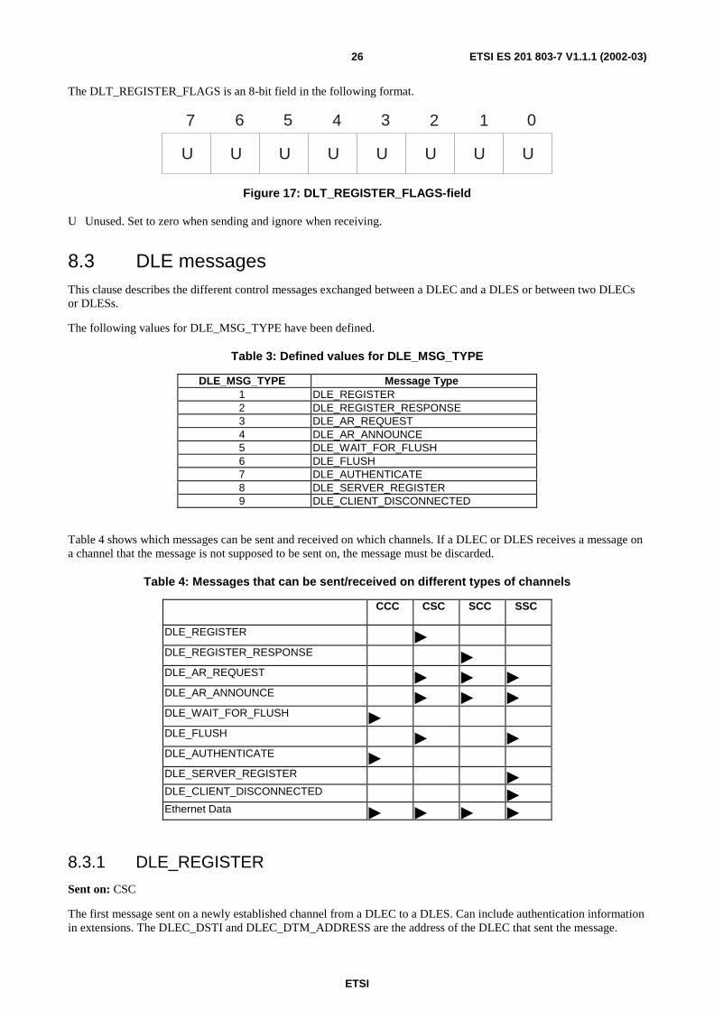
Table 4 shows which messages can be sent and received on which channels. If a DLEC or DLES receives a message on a channel that the message is not supposed to be sent on, the message must be discarded.
Table 4: Messages that can be sent/received on different types of channels
CCC CSC SCC SSC
DLE_REGISTER � DLE_REGISTER_RESPONSE � �DLE_AR_REQUEST � � � DLE_AR_ANNOUNCE � � � DLE_WAIT_FOR_FLUSH
� DLE_FLUSH � � DLE_AUTHENTICATE
� DLE_SERVER_REGISTER
� � � � DLE_CLIENT_DISCONNECTED
� � � � Ethernet Data
� � � �
8.3.1 DLE_REGISTER
Sent on: CSC
The first message sent on a newly established channel from a DLEC to a DLES. Can include authentication information in extensions. The DLEC_DSTI and DLEC_DTM_ADDRESS are the address of the DLEC that sent the message.
ETSI
ETSI ES 201 803-7 V1.1.1 (2002-03)27
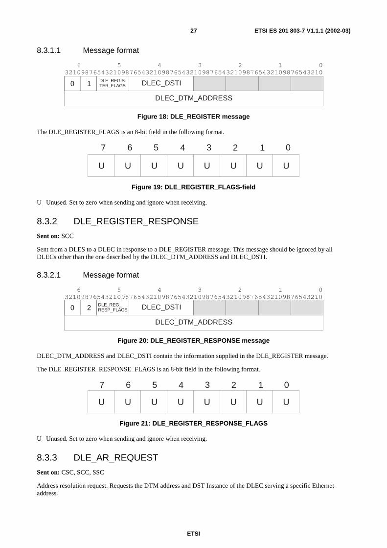
8.3.1.1 Message format
DLE_REGIS-TER_FLAGS DLEC_DSTI
DLEC_DTM_ADDRESS
0 1
Figure 18: DLE_REGISTER message
The DLE_REGISTER_FLAGS is an 8-bit field in the following format.
01234567
U U U U U U U U
Figure 19: DLE_REGISTER_FLAGS-field
U Unused. Set to zero when sending and ignore when receiving.
8.3.2 DLE_REGISTER_RESPONSE
Sent on: SCC
Sent from a DLES to a DLEC in response to a DLE_REGISTER message. This message should be ignored by all DLECs other than the one described by the DLEC_DTM_ADDRESS and DLEC_DSTI.
8.3.2.1 Message format
DLE_REG_RESP_FLAGS DLEC_DSTI
DLEC_DTM_ADDRESS
0 2
Figure 20: DLE_REGISTER_RESPONSE message
DLEC_DTM_ADDRESS and DLEC_DSTI contain the information supplied in the DLE_REGISTER message.
The DLE_REGISTER_RESPONSE_FLAGS is an 8-bit field in the following format.
U U U U U U U U
01234567
Figure 21: DLE_REGISTER_RESPONSE_FLAGS
U Unused. Set to zero when sending and ignore when receiving.
8.3.3 DLE_AR_REQUEST
Sent on: CSC, SCC, SSC
Address resolution request. Requests the DTM address and DST Instance of the DLEC serving a specific Ethernet address.
ETSI
ETSI ES 201 803-7 V1.1.1 (2002-03)28
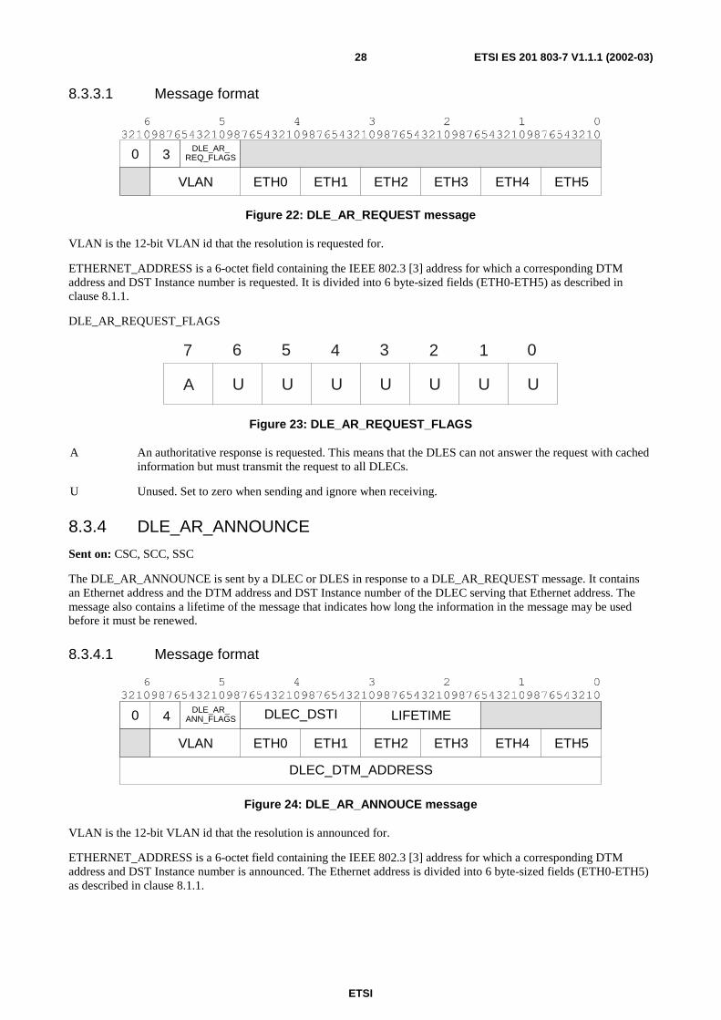
8.3.3.1 Message format
DLE_AR_REQ_FLAGS0 3
VLAN ETH0 ETH1 ETH2 ETH4 ETH5ETH3
Figure 22: DLE_AR_REQUEST message
VLAN is the 12-bit VLAN id that the resolution is requested for.
ETHERNET_ADDRESS is a 6-octet field containing the IEEE 802.3 [3] address for which a corresponding DTM address and DST Instance number is requested. It is divided into 6 byte-sized fields (ETH0-ETH5) as described in clause 8.1.1.
DLE_AR_REQUEST_FLAGS
A U U U U U U U
01234567
Figure 23: DLE_AR_REQUEST_FLAGS
A An authoritative response is requested. This means that the DLES can not answer the request with cached information but must transmit the request to all DLECs.
U Unused. Set to zero when sending and ignore when receiving.
8.3.4 DLE_AR_ANNOUNCE
Sent on: CSC, SCC, SSC
The DLE_AR_ANNOUNCE is sent by a DLEC or DLES in response to a DLE_AR_REQUEST message. It contains an Ethernet address and the DTM address and DST Instance number of the DLEC serving that Ethernet address. The message also contains a lifetime of the message that indicates how long the information in the message may be used before it must be renewed.
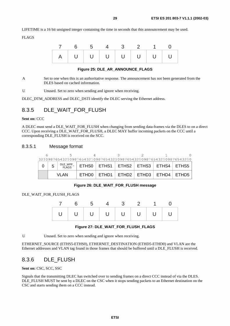
8.3.4.1 Message format
DLE_AR_ANN_FLAGS
DLEC_DTM_ADDRESS
DLEC_DSTI LIFETIME0 4
VLAN ETH0 ETH1 ETH2 ETH4 ETH5ETH3
Figure 24: DLE_AR_ANNOUCE message
VLAN is the 12-bit VLAN id that the resolution is announced for.
ETHERNET_ADDRESS is a 6-octet field containing the IEEE 802.3 [3] address for which a corresponding DTM address and DST Instance number is announced. The Ethernet address is divided into 6 byte-sized fields (ETH0-ETH5) as described in clause 8.1.1.
ETSI
ETSI ES 201 803-7 V1.1.1 (2002-03)29
LIFETIME is a 16 bit unsigned integer containing the time in seconds that this announcement may be used.
FLAGS
A U U U U U U U
01234567
Figure 25: DLE_AR_ANNOUNCE_FLAGS
A Set to one when this is an authoritative response. The announcement has not been generated from the DLES based on cached information.
U Unused. Set to zero when sending and ignore when receiving.
DLEC_DTM_ADDRESS and DLEC_DSTI identify the DLEC serving the Ethernet address.
8.3.5 DLE_WAIT_FOR_FLUSH
Sent on: CCC
A DLEC must send a DLE_WAIT_FOR_FLUSH when changing from sending data-frames via the DLES to on a direct CCC. Upon receiving a DLE_WAIT_FOR_FLUSH, a DLEC MAY buffer incoming packets on the CCC until a corresponding DLE_FLUSH is received on the SCC.
8.3.5.1 Message format
DLE_WFF_FLAGS0 5
VLAN ETHD0
ETHS0
ETHD1
ETHS1
ETHD2
ETHS2
ETHD4
ETHS4
ETHD5
ETHS5
ETHD3
ETHS3
Figure 26: DLE_WAIT_FOR_FLUSH message
DLE_WAIT_FOR_FLUSH_FLAGS
U U U U U U U U
01234567
Figure 27: DLE_WAIT_FOR_FLUSH_FLAGS
U Unused. Set to zero when sending and ignore when receiving.
ETHERNET_SOURCE (ETHS5-ETHS0), ETHERNET_DESTINATION (ETHD5-ETHD0) and VLAN are the Ethernet addresses and VLAN tag found in those frames that should be buffered until a DLE_FLUSH is received.
8.3.6 DLE_FLUSH
Sent on: CSC, SCC, SSC
Signals that the transmitting DLEC has switched over to sending frames on a direct CCC instead of via the DLES. DLE_FLUSH MUST be sent by a DLEC on the CSC when it stops sending packets to an Ethernet destination on the CSC and starts sending them on a CCC instead.
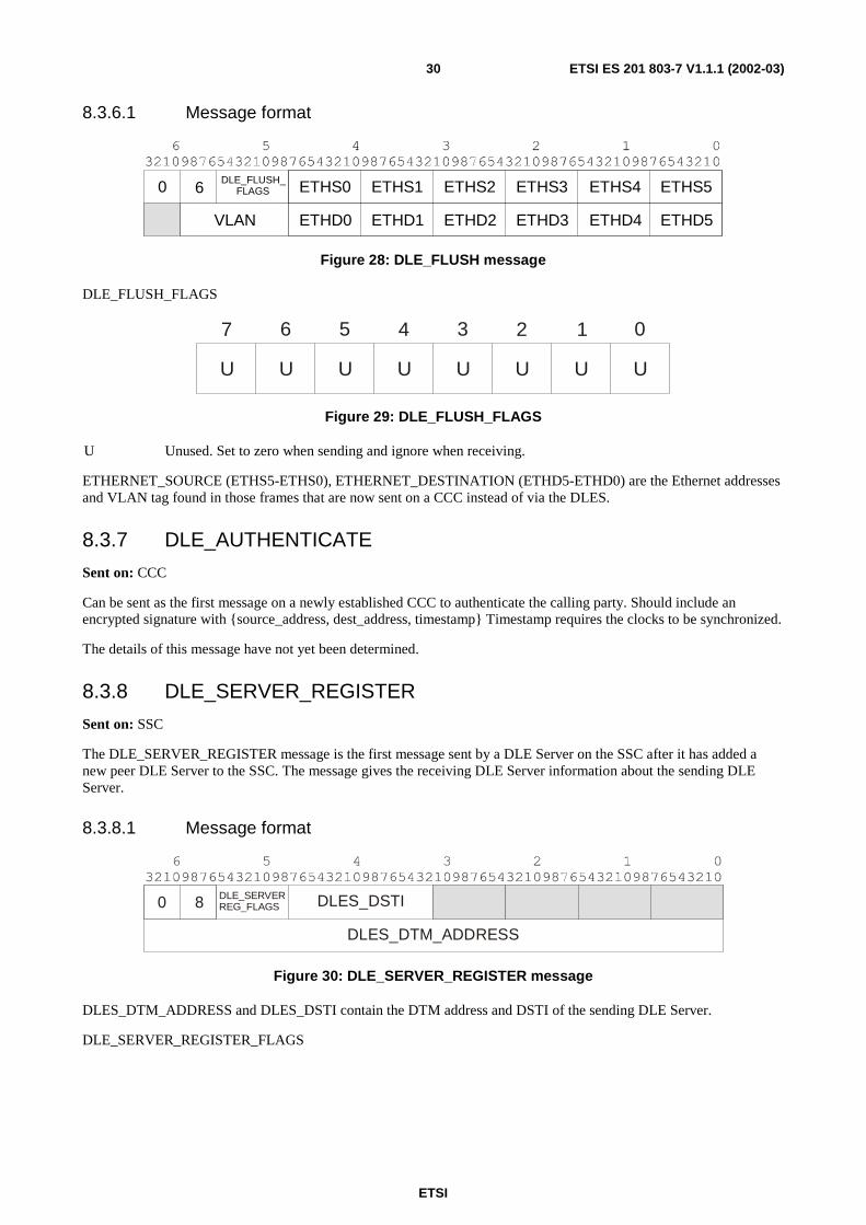
ETSI
ETSI ES 201 803-7 V1.1.1 (2002-03)30
8.3.6.1 Message format
DLE_FLUSH_FLAGS0 6
VLAN ETHD0
ETHS0
ETHD1
ETHS1
ETHD2
ETHS2
ETHD4
ETHS4
ETHD5
ETHS5
ETHD3
ETHS3
Figure 28: DLE_FLUSH message
DLE_FLUSH_FLAGS
U U U U U U U U
01234567
Figure 29: DLE_FLUSH_FLAGS
U Unused. Set to zero when sending and ignore when receiving.
ETHERNET_SOURCE (ETHS5-ETHS0), ETHERNET_DESTINATION (ETHD5-ETHD0) are the Ethernet addresses and VLAN tag found in those frames that are now sent on a CCC instead of via the DLES.
8.3.7 DLE_AUTHENTICATE
Sent on: CCC
Can be sent as the first message on a newly established CCC to authenticate the calling party. Should include an encrypted signature with {source_address, dest_address, timestamp} Timestamp requires the clocks to be synchronized.
The details of this message have not yet been determined.
8.3.8 DLE_SERVER_REGISTER
Sent on: SSC
The DLE_SERVER_REGISTER message is the first message sent by a DLE Server on the SSC after it has added a new peer DLE Server to the SSC. The message gives the receiving DLE Server information about the sending DLE Server.
8.3.8.1 Message format
DLE_SERVERREG_FLAGS DLES_DSTI
DLES_DTM_ADDRESS
0 8
Figure 30: DLE_SERVER_REGISTER message
DLES_DTM_ADDRESS and DLES_DSTI contain the DTM address and DSTI of the sending DLE Server.
DLE_SERVER_REGISTER_FLAGS
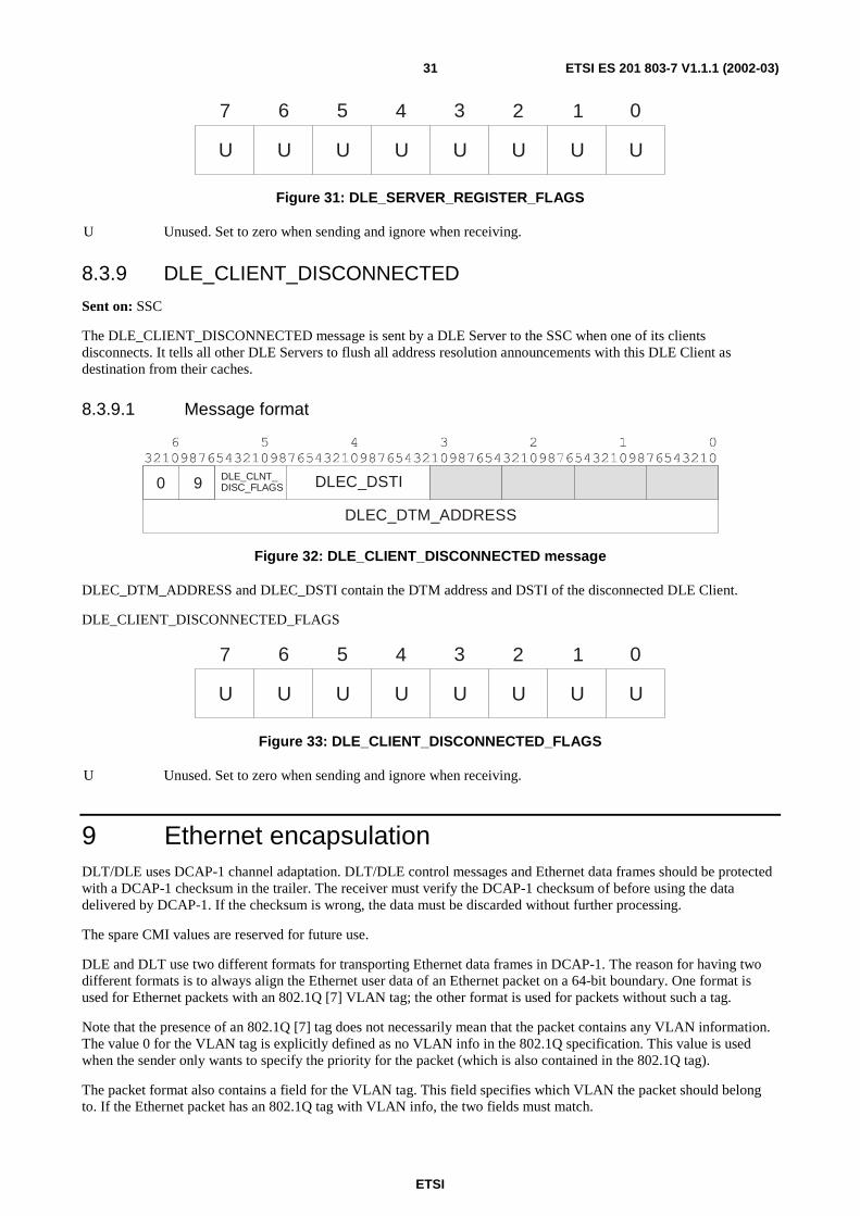
ETSI
ETSI ES 201 803-7 V1.1.1 (2002-03)31
U U U U U U U U
01234567
Figure 31: DLE_SERVER_REGISTER_FLAGS
U Unused. Set to zero when sending and ignore when receiving.
8.3.9 DLE_CLIENT_DISCONNECTED
Sent on: SSC
The DLE_CLIENT_DISCONNECTED message is sent by a DLE Server to the SSC when one of its clients disconnects. It tells all other DLE Servers to flush all address resolution announcements with this DLE Client as destination from their caches.
8.3.9.1 Message format
DLE_CLNT_DISC_FLAGS DLEC_DSTI
DLEC_DTM_ADDRESS
0 9
Figure 32: DLE_CLIENT_DISCONNECTED message
DLEC_DTM_ADDRESS and DLEC_DSTI contain the DTM address and DSTI of the disconnected DLE Client.
DLE_CLIENT_DISCONNECTED_FLAGS
U U U U U U U U
01234567
Figure 33: DLE_CLIENT_DISCONNECTED_FLAGS
U Unused. Set to zero when sending and ignore when receiving.
9 Ethernet encapsulation DLT/DLE uses DCAP-1 channel adaptation. DLT/DLE control messages and Ethernet data frames should be protected with a DCAP-1 checksum in the trailer. The receiver must verify the DCAP-1 checksum of before using the data delivered by DCAP-1. If the checksum is wrong, the data must be discarded without further processing.
The spare CMI values are reserved for future use.
DLE and DLT use two different formats for transporting Ethernet data frames in DCAP-1. The reason for having two different formats is to always align the Ethernet user data of an Ethernet packet on a 64-bit boundary. One format is used for Ethernet packets with an 802.1Q [7] VLAN tag; the other format is used for packets without such a tag.
Note that the presence of an 802.1Q [7] tag does not necessarily mean that the packet contains any VLAN information. The value 0 for the VLAN tag is explicitly defined as no VLAN info in the 802.1Q specification. This value is used when the sender only wants to specify the priority for the packet (which is also contained in the 802.1Q tag).
The packet format also contains a field for the VLAN tag. This field specifies which VLAN the packet should belong to. If the Ethernet packet has an 802.1Q tag with VLAN info, the two fields must match.
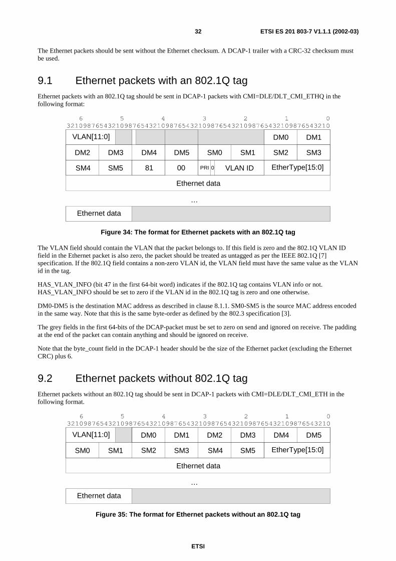
ETSI
ETSI ES 201 803-7 V1.1.1 (2002-03)32
The Ethernet packets should be sent without the Ethernet checksum. A DCAP-1 trailer with a CRC-32 checksum must be used.
9.1 Ethernet packets with an 802.1Q tag Ethernet packets with an 802.1Q tag should be sent in DCAP-1 packets with CMI=DLE/DLT_CMI_ETHQ in the following format:
Ethernet data
…
EtherType[15:0]81 00
DM0 DM1
DM2 DM3 DM4 DM5
VLAN[11:0]
Ethernet data
SM0
PRI 0 VLAN ID
SM1 SM2 SM3
SM4 SM5
Figure 34: The format for Ethernet packets with an 802.1Q tag
The VLAN field should contain the VLAN that the packet belongs to. If this field is zero and the 802.1Q VLAN ID field in the Ethernet packet is also zero, the packet should be treated as untagged as per the IEEE 802.1Q [7] specification. If the 802.1Q field contains a non-zero VLAN id, the VLAN field must have the same value as the VLAN id in the tag.
HAS_VLAN_INFO (bit 47 in the first 64-bit word) indicates if the 802.1Q tag contains VLAN info or not. HAS_VLAN_INFO should be set to zero if the VLAN id in the 802.1Q tag is zero and one otherwise.
DM0-DM5 is the destination MAC address as described in clause 8.1.1. SM0-SM5 is the source MAC address encoded in the same way. Note that this is the same byte-order as defined by the 802.3 specification [3].
The grey fields in the first 64-bits of the DCAP-packet must be set to zero on send and ignored on receive. The padding at the end of the packet can contain anything and should be ignored on receive.
Note that the byte_count field in the DCAP-1 header should be the size of the Ethernet packet (excluding the Ethernet CRC) plus 6.
9.2 Ethernet packets without 802.1Q tag Ethernet packets without an 802.1Q tag should be sent in DCAP-1 packets with CMI=DLE/DLT_CMI_ETH in the following format.
Ethernet data
…
EtherType[15:0]
Ethernet data
VLAN[11:0] DM0 DM1 DM2 DM3 DM4 DM5
SM0 SM1 SM2 SM3 SM4 SM5
Figure 35: The format for Ethernet packets without an 802.1Q tag
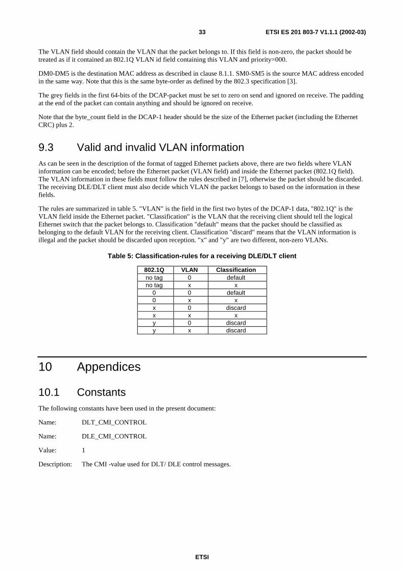
ETSI
ETSI ES 201 803-7 V1.1.1 (2002-03)33
The VLAN field should contain the VLAN that the packet belongs to. If this field is non-zero, the packet should be treated as if it contained an 802.1Q VLAN id field containing this VLAN and priority=000.
DM0-DM5 is the destination MAC address as described in clause 8.1.1. SM0-SM5 is the source MAC address encoded in the same way. Note that this is the same byte-order as defined by the 802.3 specification [3].
The grey fields in the first 64-bits of the DCAP-packet must be set to zero on send and ignored on receive. The padding at the end of the packet can contain anything and should be ignored on receive.
Note that the byte_count field in the DCAP-1 header should be the size of the Ethernet packet (including the Ethernet CRC) plus 2.
9.3 Valid and invalid VLAN information As can be seen in the description of the format of tagged Ethernet packets above, there are two fields where VLAN information can be encoded; before the Ethernet packet (VLAN field) and inside the Ethernet packet (802.1Q field). The VLAN information in these fields must follow the rules described in [7], otherwise the packet should be discarded. The receiving DLE/DLT client must also decide which VLAN the packet belongs to based on the information in these fields.
The rules are summarized in table 5. "VLAN" is the field in the first two bytes of the DCAP-1 data, "802.1Q" is the VLAN field inside the Ethernet packet. "Classification" is the VLAN that the receiving client should tell the logical Ethernet switch that the packet belongs to. Classification "default" means that the packet should be classified as belonging to the default VLAN for the receiving client. Classification "discard" means that the VLAN information is illegal and the packet should be discarded upon reception. "x" and "y" are two different, non-zero VLANs.
Table 5: Classification-rules for a receiving DLE/DLT client
802.1Q VLAN Classification no tag 0 default no tag x x
0 0 default 0 x x x 0 discard x x x y 0 discard y x discard
10 Appendices
10.1 Constants The following constants have been used in the present document:
Name: DLT_CMI_CONTROL
Name: DLE_CMI_CONTROL
Value: 1
Description: The CMI -value used for DLT/ DLE control messages.
ETSI
ETSI ES 201 803-7 V1.1.1 (2002-03)34
Name: DLT_CMI_ETH
Name: DLE_CMI_ETH
Value: 4
Description: The CMI -value used for Ethernet packets without an 802.1Q tag.
Name: DLT_CMI_ETHQ
Name: DLE_CMI_ETHQ
Value: 5
Description: The CI-value used for Ethernet packets with an 802.1Q tag.
Name: DLT_DST_MULTI
Value: 8 (as defined in ES 201 803-2- 2, see Bibliography)
Description: The DST-value used for channels between two DLT clients with both control messages and Ethernet packets.
Name: DLE_DST_MULTI
Value: 1 (as defined in ES 201 803-2- 2, see Bibliography)
Description: The DST-value used for channels between two DLECs or a DLEC and a DLES with both control messages and Ethernet packets.
Name: DLE_DST_S_MULTI
Value: 5 (as defined in ES 201 803-2- 2, see Bibliography)
Description: The DST-value used for channels between two DLESs with both control messages and Ethernet packets.
10.2 Configuration Parameters DLT The following parameters should be possible to configure in a DLT client.
10.2.1 DLT Client Configuration
DLT_DSTI
Format: 32-bit unsigned integer
The DST Instances of this DLT client.
DLT_PEER_DTM_ADDRESS
Format: 64-bit DTM addresses.
The DTM addresses of the peer DLT client.
ETSI
ETSI ES 201 803-7 V1.1.1 (2002-03)35
DLT_PEER_DSTI
Format: 32-bit unsigned integer
The DST Instances of the peer DLT client.
DLT_ETHERNET_ADDRESS
Format: 48-bit Ethernet MAC address.
The Ethernet address of this DLT client. This parameter is read-only. It should be assigned a value that is unique for this DLT connection based on the available hardware. This address should be used for spanning-tree support in the future.
DLT_ALLOWED_VLANS
Format: Array of 12-bit VLAN ids.
The allowed VLAN ids for this DLT client.
DLT_DEFAULT_VLAN
Format: 12-bit VLAN id.
The default VLAN for this DLT client. All packets received on the connection with VLAN=0 should be classified as belonging to DLT_DEFAULT_VLAN. DLT_DEFAULT_VLAN cannot be zero.
10.3 Configuration parameters DLE The following parameters should be possible to configure in a DLEC/DLES.
10.3.1 DLEC configuration
DLEC_ANNOUNCE_LIFETIME
Format: 16-bit unsigned integer
Default: 300
Minimum: 60
Maximum: 43 200
Lifetime in seconds of address resolution announcements sent out by this DLEC.
DLEC_DLES_DTM_ADDRESS
Format: Array of 64-bit DTM addresses.
The DTM addresses of the DLE Servers serving this DLEC.
DLEC_DLES_DSTI
Format: 32-bit unsigned integer
The DST Instances of the DLE Servers serving this DLEC. Each position in this array corresponds to the same position in the DLEC_DLES_DTM_ADDRESS array.
DLEC_AR_REQUEST_TIMEOUT
Format: 16-bit unsigned integer
Default: 5 000
Minimum: 100
Maximum: 60 000
ETSI
ETSI ES 201 803-7 V1.1.1 (2002-03)36
The number of milliseconds before a DLEC is allowed to retransmit a DLE_AR_REQUEST when it hasn't received a corresponding announcement.
DLEC_WAIT_FOR_FLUSH_TIMEOUT
Format: 16-bit unsigned integer
Default: 500
Minimum: 0
Maximum: 2 000
The number of milliseconds a DLEC should wait for a FLUSH message after receiving a WAIT_FOR_FLUSH message.
DLEC_FLUSH_TIMEOUT
Format: 16-bit unsigned integer
Default: 1 000
Minimum: 100
Maximum: 10 000
The number of milliseconds a FLUSH message should be stored if a corresponding WAIT_FOR_FLUSH has not been received. If the FLUSH message is discarded too early, the WAIT_FOR_FLUSH message may arrive after the FLUSH message has been discarded and force the receiving DLEC to buffer the arriving Ethernet frames until for DLEC_WAIT_FOR_FLUSH_TIMEOUT milliseconds.
DLEC_FLOW_TIMEOUT
Format: 32-bit unsigned integer
Default: 20 000
Minimum: 1 000
The number of milliseconds a CCC must be kept open when no frames are being sent on it. After a period of DLEC_FLOW_TIMEOUT milliseconds during which no frames have been sent on a CCC, the sending DLEC may close the channel.
DLEC_REGISTER_MAX_WAIT
Format: 16-bit unsigned integer
Default: 1 000 (10 000 ms)
Minimum: 10 (100 ms)
Maximum: 10 000 (100 000 ms)
The maximum retransmission time, in units of 10 ms.
DLEC_REGISTER_MIN_WAIT
Format: 16-bit unsigned integer
Default: 1 (10 ms)
Minimum: 1 (10 ms)
Maximum: 1 000 (10 000 ms)
The minimum retransmission time, in units of 10 ms.
ETSI
ETSI ES 201 803-7 V1.1.1 (2002-03)37
DLEC_REGISTER_RETRY_TIMEOUT
Format: 16-bit unsigned integer
Default: 1 000
Minimum: 100
Maximum: 10 000
The number of milliseconds a DLEC should wait for a DLE_REGISTER_RESPONSE message from the DLES after sending a DLE_REGISTER message to the DLES.
DLEC_REGISTER_RETRIES
Format: 8-bit unsigned integer
Default: 2
Minimum: 0
Maximum: 10
The number of times a DLEC should resend a DLE_REGISTER message to the DLES when it doesn't receive a DLE_REGISTER_RESPONSE message from the DLES.
DLEC_ETHERNET_ADDRESS
Format: 48-bit Ethernet MAC address.
The Ethernet address of this DLEC. This parameter is read-only. It should be assigned a value that is unique for this DLE segment based on the available hardware.
DLEC_DEFAULT_VLAN
Format: 12-bit VLAN id.
The default VLAN id for this DLE Client. Note that this need not be the same for all DLE Clients in a DLE segment.
DLEC_ALLOWED_VLANS
Format: Array of 12-bit VLAN ids.
The allowed VLAN ids for this DLE segment. The default VLAN id should not be specified here, it is always allowed.
10.3.1 DLES configuration
DLES_ANNOUNCE_LIFETIME
Format: 16-bit unsigned integer
Default: 300
Minimum: 60
Maximum: 43 200
Lifetime in seconds of address resolution announcements sent out by this DLES. If the DLES receives an announcement from a DLEC with a lifetime larger than ANNOUNCE_LIFETIME, it must decrease the lifetime of the announcement to ANNOUNCE_LIFETIME before sending the announcement on the SCC.
DLES_REGISTER_MAX_WAIT
Format: 32-bit unsigned integer
Default: 1 000 (10 000 ms)
ETSI
ETSI ES 201 803-7 V1.1.1 (2002-03)38
Minimum: 100 (1 000 ms)
Maximum: 100 000 (1 000 000 ms)
The maximum retransmission time, in units of 10 ms.
DLES_REGISTER_MIN_WAIT
Format: 16-bit unsigned integer
Default: 100 (1 000 ms)
Minimum: 10 (100 ms)
Maximum: 10 000 (100 000 ms)
The minimum retransmission time, in units of 10 ms.
DLES_DSTI
Format: 16-bit unsigned integer
Default: 0
The DSTI value that should be used by this DLES.
DLES_PEERS_DTM_ADDRESS
Format: Array of 64-bit DTM addresses.
The DTM addresses of all the peer DLE Servers.
DLES_PEERS_DSTI
Format: Array of 16-bit unsigned integers.
The DSTI values for all the peer DLE Servers specified in DLES_PEERS_DTM_ADDRESS
ETSI
ETSI ES 201 803-7 V1.1.1 (2002-03)39
Annex A (informative): Bibliography ETSI ES 201 803-2-1: "Dynamic synchronous Transfer Mode (DTM); Part 2: System characteristics, Sub-part 1: Data link aspects".
ETSI ES 201 803-2-2: "Dynamic synchronous Transfer Mode (DTM); Part 2: System characteristics; Sub-part 2: Network aspects".
ITU-T Recommendation G.805: "Generic functional architecture of transport networks".
ITU-T Recommendation G.806: "Characteristics of Transport Equipment - Description Methodology and Generic Functionality".
ETSI
ETSI ES 201 803-7 V1.1.1 (2002-03)40
History
Document history
V1.1.1 March 2002 Membership Approval Procedure MV 20020503: 2002-03-05 to 2002-05-03