Mozambique Tyre Tracking - RFID tags, RFID readers, RFID ...
Error-resistant RFID-assisted wireless sensor networks for cardiac telehealthcare
17
WIRELESS COMMUNICATIONS AND MOBILE COMPUTING Wirel. Commun. Mob. Comput. 2009; 9:85–101 Published online 28 February 2008 in Wiley InterScience (www.interscience.wiley.com) DOI: 10.1002/wcm.607 Error-resistant RFID-assisted wireless sensor networks for cardiac telehealthcare Fei Hu 1 , Laura Celentano 1 and Yang Xiao 2 * ,y 1 Department of Computer Engineering, RIT, Rochester, NY, U.S.A. 2 Department of Computer Science, The University of Alabama, Tuscaloosa, AL, U.S.A. Summary Wireless transmission of a patient’s electrocardiogram (ECG) signals can be used to reduce cardiac healthcare cost. However, wireless transmissions have high error rates due to radio interference. The ECG signal, where every second of data could mean abnormal patterns, cannot tolerate such losses. Due to this healthcare crisis, the ability for a device to remotely monitor a patient’s medication intake and transmit accurate ECG readings, while being cost efficient, is a major innovation. In this research, we integrate a multi-hop wireless sensor network (WSN) with radio frequency identification (RFID) readers. Our system has two distinct features: (1) remotely supervise patient medication intake via RFID technology, and (2) accurately and remotely transmitting a patient’s ECG by adopting extended Kalman filter (EKF) for wireless error recovery. Copyright # 2008 John Wiley & Sons, Ltd. KEY WORDS: medical sensor networks; ECG; RFID; extended Kalman filter (EKF) 1. Introduction According to the U.S. Bureau of the Census [1], the number of adults with ages from 65 to 84 is expected to double from 35 million to nearly 70 million by 2025 when the youngest Baby Boomers retire. A recent study found that almost one-third of U.S. adults, most of whom held full-time jobs, were ser- ving as informal caregivers—mostly to an elderly parent [2]. As this burden becomes too great and more elderly patients head to nursing homes, it will become very important to build a remote telehealth monitoring system that can continuously, automatically, accu- rately, and cost effectively monitor medical signals such as a patient’s medication intake and electrocar- diogram (ECG) signal. Telehealth monitoring can be defined as ‘mobile computing, medical sensor, and communications technologies for healthcare.’ This represents the evo- lution of e-health systems from traditional desktop ‘telemedicine’ platforms to wireless/mobile config- urations [3]. While patient monitoring has conven- tionally been assigned to trained medical care personnel, putting some responsibility in the hands of the patient could alleviate a considerable amount of the staff’s workload. This would free medical profes- sionals from a tedious task and allow them to center their attention on more demanding medical emergen- cies. Industry has taken notice of the need for remote medical monitoring and several companies have come out with products to remotely and wirelessly monitor *Correspondence to: Yang Xiao, Department of Computer Science, The University of Alabama, Tuscaloosa, AL, U.S.A. y E-mail: [email protected] Copyright # 2008 John Wiley & Sons, Ltd.
Transcript of Error-resistant RFID-assisted wireless sensor networks for cardiac telehealthcare

WIRELESS COMMUNICATIONS AND MOBILE COMPUTINGWirel. Commun. Mob. Comput. 2009; 9:85–101Published online 28 February 2008 in Wiley InterScience(www.interscience.wiley.com) DOI: 10.1002/wcm.607
Error-resistant RFID-assisted wireless sensor networksfor cardiac telehealthcare
Fei Hu1, Laura Celentano1 and Yang Xiao2*,y1Department of Computer Engineering, RIT, Rochester, NY, U.S.A.2Department of Computer Science, The University of Alabama, Tuscaloosa, AL, U.S.A.
Summary
Wireless transmission of a patient’s electrocardiogram (ECG) signals can be used to reduce cardiac healthcare
cost. However, wireless transmissions have high error rates due to radio interference. The ECG signal, where every
second of data could mean abnormal patterns, cannot tolerate such losses. Due to this healthcare crisis, the ability
for a device to remotely monitor a patient’s medication intake and transmit accurate ECG readings, while being
cost efficient, is a major innovation. In this research, we integrate a multi-hop wireless sensor network (WSN) with
radio frequency identification (RFID) readers. Our system has two distinct features: (1) remotely supervise patient
medication intake via RFID technology, and (2) accurately and remotely transmitting a patient’s ECG by adopting
extended Kalman filter (EKF) for wireless error recovery. Copyright # 2008 John Wiley & Sons, Ltd.
KEY WORDS: medical sensor networks; ECG; RFID; extended Kalman filter (EKF)
1. Introduction
According to the U.S. Bureau of the Census [1], the
number of adults with ages from 65 to 84 is expected
to double from 35 million to nearly 70 million by
2025 when the youngest Baby Boomers retire. A
recent study found that almost one-third of U.S.
adults, most of whom held full-time jobs, were ser-
ving as informal caregivers—mostly to an elderly
parent [2]. As this burden becomes too great and more
elderly patients head to nursing homes, it will become
very important to build a remote telehealth monitoring
system that can continuously, automatically, accu-
rately, and cost effectively monitor medical signals
such as a patient’s medication intake and electrocar-
diogram (ECG) signal.
Telehealth monitoring can be defined as ‘mobile
computing, medical sensor, and communications
technologies for healthcare.’ This represents the evo-
lution of e-health systems from traditional desktop
‘telemedicine’ platforms to wireless/mobile config-
urations [3]. While patient monitoring has conven-
tionally been assigned to trained medical care
personnel, putting some responsibility in the hands
of the patient could alleviate a considerable amount of
the staff’s workload. This would free medical profes-
sionals from a tedious task and allow them to center
their attention on more demanding medical emergen-
cies.
Industry has taken notice of the need for remote
medical monitoring and several companies have come
out with products to remotely and wirelessly monitor
*Correspondence to: Yang Xiao, Department of Computer Science, The University of Alabama, Tuscaloosa, AL, U.S.A.yE-mail: [email protected]
Copyright # 2008 John Wiley & Sons, Ltd.

a patient’s ECG. Unfortunately, wireless transmis-
sions have an error rate many times that of a tradi-
tional wired network. While there’s a need to decrease
the one-on-one time staff have with each patient, it
must be done safely. A loss in medical data typical of
that seen in wireless transmissions cannot be toler-
ated—each piece of cardiac data could carry impor-
tant medical information. For example, a sudden heart
failure may produce an abnormal ECG signal that
lasts for only a few seconds. The transmission error of
such a segment of ECG data is disastrous to the
capture of, and response to, sudden heart failure
events.
Based on these motivations, remote medication and
accurate ECG monitoring, there have been a number
of attempts to develop medical systems similar to the
proposed work in this research, but they have fallen
short. While these systems monitor dispensing med-
ication to patients using radio frequency identification
(RFID), [4] they do not oversee the actual application
of the drugs by the patient. In addition, such systems
employ an expensive communication infrastructure.
For nursing homes that are regional areas, expensive
cellular networks and wireless LANs should be
avoided. Instead, a low-cost, short-distance telehealth-
care system is preferred. Other handheld devices on
the open market that use RFID to manage medication
are not part of network and do not allow any monitor-
ing by healthcare personnel, putting all the responsi-
bility in the hands of the patient. Finally, in the
systems that wirelessly monitor a patient’s ECG,
transmission errors are likely and cannot be tolerated.
This research designed a wearable medication
monitoring platform which hosts an RFID reader
and is capable of RF communication. The patient
will be able to scan any of their medication bottles
containing an RFID tag and wirelessly transmit the
attempted drug application to a central workstation.
The workstation queries a central database which
contains the proper administration for the given med-
ication. If for any reason the patient is improperly
taking this drug, they will be alerted by a red LED
toggle on their wearable device. Additionally, the
healthcare employee handling the workstation will
also receive a pop-up message indicating that a patient
has attempted to improperly take a drug. It is then at
their discretion whether to call the patient to follow-
up, to check the problem, or to physically visit the
patient.
To avoid a high-cost network while still attaining
long range distance from the central workstation, the
network adopts multi-hop communication, using each
patient’s wearable sensor as a hop. By using patients
as hops rather than statically placed sensors, the net-
work achieves the same effect while making more
efficient use of resources. Finally, in showcase the
possibility of achieving more reliable ECG transmis-
sions, the extended Kalman filter (EKF) [5] is applied
to real ECG signals (with simulated data losses) from
a cardiac database. Although there have been many
research efforts in both of the fields of medical asset
monitoring and remote ECG monitoring [6–18], most
of them stay theoretical at the best. This research
marks an attempt to bridge the two research fields by
providing a product that is realizable and would
directly benefit the consumers in the medical field.
The rest of this paper is organized in the following
way. Section 2 provides some background informa-
tion on the topics of RFID, the Kalman filter, as well
as others works supporting this work. In Sections 3–5,
we provide more insights of the implementation of the
wearable platform with multi-hop communication and
using the EKF to recover wireless ECG transmission
losses. We conclude this paper in Section 6.
2. Background
In this section, we briefly provide some foundational
information on the subjects of RFID and its use in
telehealthcare, the Kalman filter, wireless sensor net-
works (WSNs), and the supporting work environment.
2.1. RFID
RFID is a method of storing and retrieving data,
similar to the theory of the barcode [19,20]. With
RFID, the electromagnetic or electrostatic coupling in
the RF portion of the electromagnetic spectrum is
used to transmit signals. An RFID system consists of a
reader and any number of tags. The reader contains an
antenna and a transceiver, which both work to read the
RF and transfer the information to a processing
device. The tag, or transponder, is an integrated circuit
containing the RF circuitry and information to be
transmitted. There are generally two types of tags,
passive and active.
RFID has been used to replace Universal Product
Code (UPC) in supply chain/object mobility monitor-
ing applications in many organizations such as Wal-
mart and the Department of Defense [21]. Industry
and telehealthcare corporations have seen the success
and usefulness of RFID and are now beginning to
incorporate it into healthcare scenarios to alleviate
86 F. HU, L. CELENTANO AND Y. XIAO
Copyright # 2008 John Wiley & Sons, Ltd. Wirel. Commun. Mob. Comput. 2009; 9:85–101
DOI: 10.1002/wcm

errors and to cut down costs. For examples a Location-
based Medicare Service (LBMS) was implemented in
Taipei Medical University Hospital which used RFID
tags to locate both patients and hospital assets with
successful results [21]. Exavera’s eSheperd uses RFID
over a WiFi network to track patients, staff, and
supplies, including medication dispensed to patients
by the staff [22].
En-Vision America has created a new way to
provide prescription information to the user using
RFID with ScripTalk [23]. When a patient using a
ScripTalk reader submits a prescription, the pharmacy
software prints and programs an auxiliary smart label
using a dedicated, small-footprint printer. The smart
label, which stores prescription information, is placed
onto the prescription container by the pharmacist. In
the home, the patient uses a handheld ScripTalk
Reader that speaks out the label information using
speech synthesis technology.
Unfortunately, the first of these systems puts the
actual medication intake into the hands of the patient;
they all rely on staff dispensing. Additionally, they
require wireless LAN access points and an expensive
infrastructure. While the last system mentioned does
put medication administration into the hands of the
patient, it is not part of a network and therefore cannot
be supervised by staff.
The RFID-based medication monitoring system
proposed in this work/paper does not require an
expensive infrastructure. Instead it uses an ad hoc
network [24] consisting of wireless sensors which
host RFID readers. These sensors are worn by all
patients and are used to scan their medication bottles
containing RFID tags. The tag read is transmitted to a
central work station which contains a central database.
By referencing the database, it is determined if the
medication should be taken or not. If the medication
should not be taken, for any reason, the patient will be
alerted with a red LED toggle on their sensor. Ad-
ditionally, a popup will appear on the central work-
station citing the patient, the time of the incorrect
application, and what the medication was. The sensors
will utilize multi-hop communication so that they can
communicate with the workstation even when out of
transmission range. Staff members no longer need to
make rounds to supervise patients taking their medi-
cation, it can be done remotely.
2.2. Error-Resistant ECG Transmission
For our purposes, the wearable devices are assumed to
be equipped with ECG sensors. It is also assumed that
ECG interpretation software will be running on the
central workstation where all data (medication intake
and ECG signals) are being sent. Such a system is
referred to as a cardiac sensor network (CSN). Radio-
based wireless networks are suitable to patients’
mobility behavior. However, the wireless error rate
is around 2–10% [25]. This is much higher than
traditional wired networks, such as cable-based med-
ical networks, which only have 10�9 error rate.
As mentioned earlier, many medical data errors
cannot be tolerated because each piece of cardiac
data could carry important medical information.
There are several factors which can cause ECG data
errors or even data loss. They are hardware noise,
wireless signal energy loss during propagation, and
radio refection/diffraction/scattering. Hardware noise
can occur with the ECG sensors due to the circuit
interference among surface-mount parts and the lim-
ited amplifier capability. In a small ECG sensor, a tiny
amplifier is used, making it difficult to enlarge signals
to a satisfying level. Wireless signal energy loss
during propagation can be attributed to the well-
known fact that the received wireless signal strength
decreases when distance from the sender increases.
This can be seen from the following equation, where d
is the distance [25]:
Preceived / 1
d2ð1Þ
A radio wave could change its direction when
hitting objects. Radio reflection/scattering can damage
the wireless signals. An erroneous packet will be
discarded by any receiver, which causes packet loss.
Figure 1 shows one section of our collected ECG
data series. It clearly shows the data missing during
0.05–0.07 s and possible data errors during 0.09–
0.11 s. Even though the ECG values are typically
different at 0.01 s of time scale, three nearly duplicate
Fig. 1. Packet ECG data loss/errors due to wireless link.
ERROR-RESISTANT RFID-ASSISTED MEDICAL SENSOR NETWORKS 87
Copyright # 2008 John Wiley & Sons, Ltd. Wirel. Commun. Mob. Comput. 2009; 9:85–101
DOI: 10.1002/wcm
values at 0.09–0.11 s are still seen, and this indicates
data errors.
Based on this knowledge it is clear an error recov-
ery scheme must be implemented in order to obtain a
reliable CSN. For this work, the EKF is chosen to
recover wireless data loss. Before delving into the
EKF, it would be sensible to describe its more sim-
plified version, the Kalman filter.
The Kalman filter is named after Rudolph E. Kal-
man, who in 1960 published his famous paper de-
scribing a recursive filter that estimates the state of a
dynamic system from a series of incomplete and noisy
measurements. The Kalman filter is essentially a set of
mathematical equations that implement a predictor–
corrector type estimator that is optimal in the sense
that it minimizes the estimated error covariance [26].
The Kalman filter estimates a process by using a form
of feedback control, that is, the filter estimates the
process state at some time and then obtains feedback
in the form of noisy measurements. As such, the
equations for the Kalman filter fall into two groups:
time update equations and measurement update equa-
tions. The time update equations can also be thought
of as predictor equations, while the measurement
update equations can be thought of as corrector
equations [26].
For the Kalman filter, the system is assumed to be
linear; if it is nonlinear it should be linearized. While
an ECG is a nonlinear signal and therefore cannot use
the standard Kalman filter, it can be linearized and
have the EKF applied to it. This enables us to predict
what the lost pieces of wireless data and to reconstruct
the entire ECG signal. The differences in the standard
Kalman filter and the EKF, as well as linearizing an
ECG signal to be used with the EKF, will be covered
in Section 5.
2.3. Wireless Sensor Networks
WSNs are highly distributed networks of small, light-
weight wireless nodes. Each node consists of three
subsystems: a sensor subsystem which senses the
environment, a processing subsystem which performs
local computations, and a communication subsystem.
TinyOS [27] is an open source operating system
which targets WSNs. It was primarily developed by
the University of California, Berkley in cooperation
with Intel Research and is written in nesC. It has a
component-based architecture and is able to operate
within the severe memory constraints imposed by a
sensor network.
3. Integration of RFID andWearable Sensors
3.1. RFID via Mica2Dot
The RFID reader chosen for this work was SkyeTek’s
M1-Mini that is advertised as ‘the world’s smallest,
self-contained multi-protocol 13.56MHz’ low-power
RFID reader [28] and supports a radius of a mere
12.7mm. The reader requires an input voltage be-
tween 3.2 and 6V. Its current consumption is 60mA
when scanning a tag and 15mA when being idle.
ReaderWare, an open-architecture software suite re-
siding on all SkyeTek’s modules, provides intelli-
gence for the RFID reader. It has an internal antenna
which provides it with a read range of approximately
50.8mm, but this also depends on the tag type. It has
the ability to attach a standard 50� external antenna
for improved read-range as well. It is capable of
reading and writing to tags based on ISO 15693,
ISO 14443A, AND ISO 18000-3 air-interface proto-
cols. The effective read range for varying ISO 15693
tag types using the internal antenna, as done in this
work, can be seen in Table I [28].
The WSN itself includes a number of node motes,
Crossbow’s Mica2Dot, which will be equipped with
these RFID readers, and one base station mote. The
Mica2Dot acts as the host system by sending the M1-
Mini commands, as well as receiving and interpreting
its response to the given command. The Mica2Dot has
a 12.5mm radius and a 433MHz multi-channel radio
transceiver for wireless communications. It requires
an input voltage between 2.7 and 3.3V. These over-
lapping input voltages enable both reader and mote to
run off the same power supply.
The M1-Mini was designed to interface directly
with Crossbow’s Mica2Dot mote. Both the M1-Mini
reader and the Mica2Dot mote were run at a baud rate
of 9600 bits/s, the default setting for the reader, in
order to communicate. The mote was programed with
an individual node ID and continuously checked for a
tag in the reader’s read range every 2000ms via
polling. The mote sent the instruction code for
the SELECT_TAG command to the reader using
SkyeTek’s ASCII protocol, rather than the binary
Table I. Effective range for ISO 15693 tags using internal antenna.
ISO 15693 tag dimensions Effective range for internal antenna
48� 76mm2 5.0 cm38� 22.5mm2 3.5 cm
88 F. HU, L. CELENTANO AND Y. XIAO
Copyright # 2008 John Wiley & Sons, Ltd. Wirel. Commun. Mob. Comput. 2009; 9:85–101
DOI: 10.1002/wcm

protocol. This command read the ID number of the
RFID tag in the read range and delivered it to the
mote.
Communication is the biggest expenditure of power
in a WSN, and this should be minimized at all costs.
Therefore, only when a successful response was
received from the reader at the mote, indicating a
tag ID was read, was the tag ID number sent to the
awaiting base station, Crossbow’s Mica2 mote. The
RFID mote and base station mote had a communica-
tion range of approximately 150m in an enclosed
area.
Crossbow’s Mica2 mote serves as the base station
for this work. The base station’s role was to receive
and process the RFID tag ID sent by the Mica2Dot
mote, as well as the mote’s individual software Pro-
gramed ID. Any Mica2 mote can function as a base
station when it is connected to a standard PC interface
or gateway board. The MIB510 provides a serial
interface for both programming and data communica-
tion. Using the RFID tag ID and mote ID, the medical
software written for this project was able to determine
if that medication intake was appropriate for that
patient. If it was an incorrect medication intake for
the patient, the base station sends a command back to
the original node mote to toggle its red LED.
3.2. Medical Software System
We have developed two software applications. The
first is called RIT Medi-Write, while the second is
called RIT Medi-View. Medi-Write allows a physi-
cian to program an RFID tag, while Medi-View alerts
the physician and patient when an incorrect medica-
tion application was attempted. Both were created
using Microsoft Visual Cþþ 6.0.
3.2.1. RIT Medi-Write
When using this application, the practitioner will use
SkyeTek’s M1 RFID reader, which follows the same
protocol as the M1-Mini, but has native support for
RS232 host interface and a supply voltage of 1.8–
5.0V. As stated before, Medi-Write allows a practi-
tioner to fill out all prescription information on an
RFID tag, which is destined to be applied on a
medication bottle. The tag will contain the patient’s
name, the name of the prescription, the quantity of
medication in the bottle, the dose size, the doses
needed per day, and the software programed node
(reader) ID, which would be printed on the unit if this
system were to be manufactured.
The practitioner places the RFID tag over the
reader, fills in all the fields with the previously men-
tioned information, and hits the ‘Write Tag’ button. If
they would like to check that all information
was appropriately entered, all they need do is press
the ‘Read Tag’ button and the fields will be filled
with the data they previously entered. If it is found
that a mistake was made after reading the tag infor-
mation back, the practitioner can simply correct the
appropriate field and re-write to the tag. The status
box above the buttons informs the practitioner
whether the read or write has failed or completed
successfully.
3.2.2. MySQL database
Behind the scenes, when the ‘Write Tag’ button is
pressed a new entry will be placed in the database [29]
with all the information supplied by the practitioner,
plus the RFID tag’s ID. The tag ID is stored under
the database field name tagID. There is also a
field in the database, doseToday, for how many
doses of that medication were taken for the current
day. This is set to 0 when a new entry is added. A
screenshot of the current database contents can be
seen in Figure 2.
The correlation between the field names in
Medi-Write and the database field names is shown
in Table II. Re-writing to the tag will erase the
previous entry for it in the database and enter a new
Fig. 2. Database screenshot.
ERROR-RESISTANT RFID-ASSISTED MEDICAL SENSOR NETWORKS 89
Copyright # 2008 John Wiley & Sons, Ltd. Wirel. Commun. Mob. Comput. 2009; 9:85–101
DOI: 10.1002/wcm

entry with the correct data. The database will never
retain two entries for the same tag.
3.2.3. RIT Medi-View
The Medi-View application is the real software cen-
terpiece. It is in charge of alerting the healthcare
personnel member at the central workstation of an
inappropriate medication application. Additionally, it
must instruct the base station mote to send an alert to
the original sending patient mote. Since this applica-
tion’s only graphical requirement is to provide alerts
to the personnel at the workstation, the program is
comprised of a simple terminal window, which dis-
plays various status messages, and pop-up windows,
which appear when an inappropriate medication ap-
plication was attempted.
The terminal window displays status messages on
the system. It relays to the user if it is successfully
connected to the serial port and the database. Regard-
less of what the software is receiving over the serial
port, it updates the database at the beginning of each
new day, 12 AM. It must reset the doseToday field in
the database to 0 for every database entry. When this
occurs, a message is also displayed in the terminal
window. Finally, when the program does receive data
via the serial port, it will display the tag and mote ID
in the terminal window.
In addition to the pop-ups, there is an audible
‘beep’ generated when inappropriate medication
was attempted to be taken. The pop-ups and beeps
are the only elements of the software the personnel
truly need be concerned with, not the status mes-
sages in the terminal window. Once the base station
mote has received a tag and mote ID, it sends it via
serial communication, provided by the gateway
MIB510 board, to the workstation. When the work-
station has this information, it can reference the
database to ensure the patient is properly taking
their medication. First, an account of the program’s
actions will be provided for a correctly taken med-
ication. This will then be followed by the situations
where the medication was taken inappropriately.
It should be stated this program is continually
polling to see if a tag and mote ID combo has been
received. A state diagram of the program can be seen
in Figure 3.
In the event that a patient is correctly taking their
medication, the database doseToday field will be
incremented by 1, and the QTY field will be decre-
mented by whatever the value of the doseSize field is.
In this case, no information is sent serially back to the
base station. This is because an alert does not need to
be sent to the patient.
There are several situations in which the patient and
healthcare personnel will receive an alert, including
the given medication not being in the database, a
patient attempting to take medication that is not
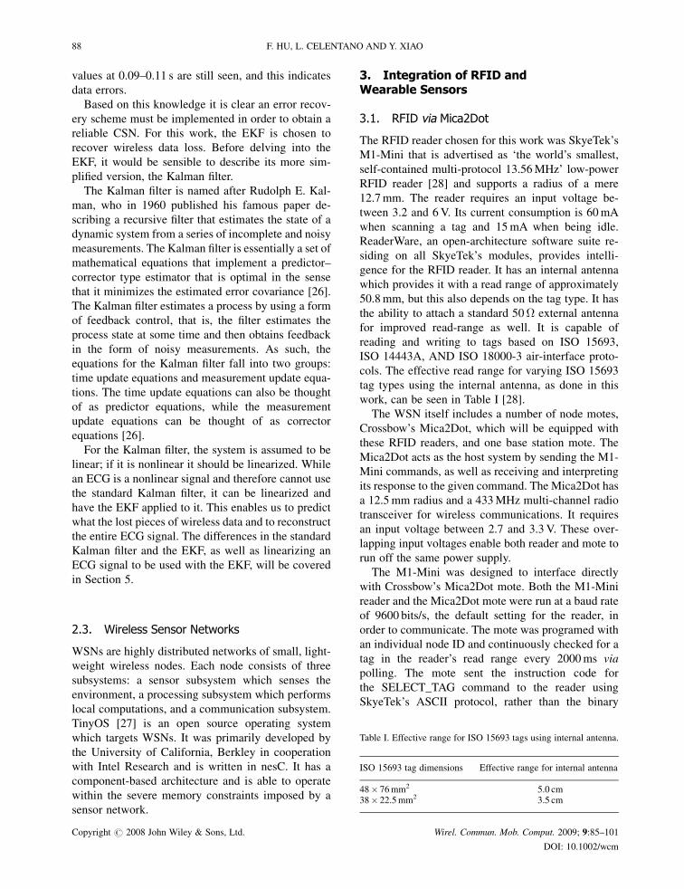
their own, if the patient is out of pills, and finally,
their taking not the required doses of that medication
for the day. For each of these errors, a pop-up will be
displayed containing a time stamp, the patient who is
incorrectly taking their medication, and the reason the
application was incorrect.
It is possible to determine if a medication is in the
database by looking up the RFID tag ID under
the tagID field in the database. If it does not exist
in the database, it will not be entered into the system,
and an alert should be sent. To check if a patient is
taking medication that is not their own, look up the
tag ID in the database. If this entry does not have a
value in the readerID field of the database that
matches the patient’s mote ID, the patient is attempt-
ing to take medication that is not his and an alert
must be sent. It can easily be determined if a patient
is out of pills by checking the QTY field in the
database for the corresponding tag ID received. If
the value in the QTY is 0, an alert should be sent so
that the prescription may be refilled. Finally, perhaps
most importantly is the check to ensure a patient is
not about to overdose on their medication. The
doseToday field in the database should be queried
for the corresponding tag ID. If the value in this field
is equal to the value in the doseDay field, the patient
should not be taking anymore medication. If an
attempt is made, an alert must be sent to keep the
patient from overdosing. An example pop-up mes-
sage for each of the previously described situations
can be seen in Figures 4–7. This has detailed all the
components of the RIT Medi-View. An illustrated
overview of the entire system can be seen in Figure 8.
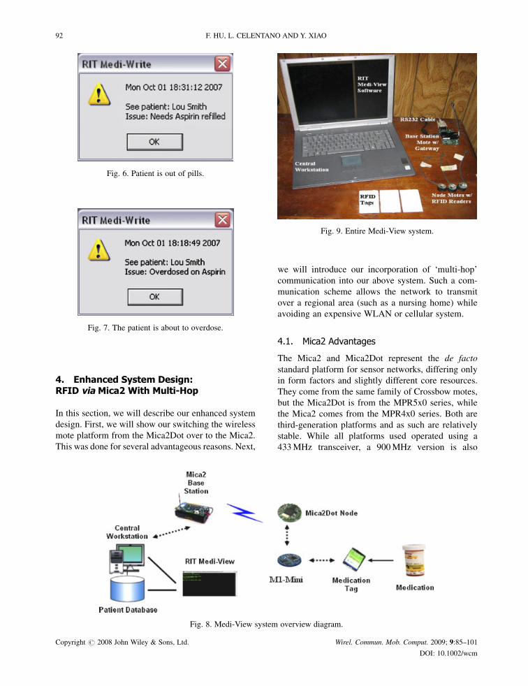
The entire physical system setup needed to run Medi-
View can be seen in Figure 9.
Table II. Correlation between Medi-Write field names and databasefield names.
Medi-Write field name Database field name
Full name NamePrescription RxQuantity QTYDose size doseSizeDoses per day doseDayReader ID readerID
90 F. HU, L. CELENTANO AND Y. XIAO
Copyright # 2008 John Wiley & Sons, Ltd. Wirel. Commun. Mob. Comput. 2009; 9:85–101
DOI: 10.1002/wcm

Fig. 3. Medi-View state diagram.
Fig. 4. The given medication is not in the database.
Fig. 5. Patient attempting to take medication that is nottheirs.
ERROR-RESISTANT RFID-ASSISTED MEDICAL SENSOR NETWORKS 91
Copyright # 2008 John Wiley & Sons, Ltd. Wirel. Commun. Mob. Comput. 2009; 9:85–101
DOI: 10.1002/wcm
4. Enhanced System Design:RFID via Mica2 With Multi-Hop
In this section, we will describe our enhanced system
design. First, we will show our switching the wireless
mote platform from the Mica2Dot over to the Mica2.
This was done for several advantageous reasons. Next,
we will introduce our incorporation of ‘multi-hop’
communication into our above system. Such a com-
munication scheme allows the network to transmit
over a regional area (such as a nursing home) while
avoiding an expensive WLAN or cellular system.
4.1. Mica2 Advantages
The Mica2 and Mica2Dot represent the de facto
standard platform for sensor networks, differing only
in form factors and slightly different core resources.
They come from the same family of Crossbow motes,
but the Mica2Dot is from the MPR5x0 series, while
the Mica2 comes from the MPR4x0 series. Both are
third-generation platforms and as such are relatively
stable. While all platforms used operated using a
433MHz transceiver, a 900MHz version is also
Fig. 6. Patient is out of pills.
Fig. 7. The patient is about to overdose.
Fig. 8. Medi-View system overview diagram.
Fig. 9. Entire Medi-View system.
92 F. HU, L. CELENTANO AND Y. XIAO
Copyright # 2008 John Wiley & Sons, Ltd. Wirel. Commun. Mob. Comput. 2009; 9:85–101
DOI: 10.1002/wcm

available. Table III below gives a side-by-side com-
parison of both platforms’ radio properties.
By inspecting this table, it is clear that both motes
possess the same physical radio. This is what allowed
communication between the two motes, as described
in Section 2. The differences between these two motes
can be seen in the system core comparison, shown in
Table IV. It is these differences, along with availability
differences, which lead to the Mica2’s superiority [30].
From Table IV, we observe that one of the noted
differences between the motes is their number of user
interface (UI) components. The Mica2Dot only comes
equipped with one red LED. This means its one light
must be reserved for alerts to the patient that medica-
tion is being incorrectly taken. Ideally, the system
should be able to give the patient confirmation that a
tag read was sent. Without this, a level of confidence is
removed from the system, as the patient can not be
sure that their medication intake was actually sent to
the base station mote. On the other hand, the Mica2 is
equipped with three LEDs, one green, one yellow, and
one red. For this platform, it was decided that the node
mote’s yellow LED should toggle when it is sending
to the base station. This allows the patient to confirm
that their intake was sent, as well as receive notifica-
tion in the event they incorrectly administered a drug.
There is one light left over which could be used during
additional development.
Another noted difference is the Mica2Dot’s dimin-
ished capacity for peripherals when compared to the
Mica2. While the Mica2Dot only has 18 input/output
(IO) pins, the Mica2 has 51. While the system
implemented in this work did not require more IO
pins than that provided by the Mica2Dot, it is envi-
sioned that this wearable device will have many more
requirements other than RFID medication supervi-
sion. As mentioned previously, the system should at
the very least also possess an ECG sensor, though
which was not implemented here. This additional
sensor would of course require additional IO pins on
the mote. It is also likely that, due to further devel-
opment, a designer would like to add a sensor to
measure a patient’s breathing rate. This again would
require the availability of more IO pins on the mote.
Clearly, as more functionality is added to the system
more IO pins need to be made available. The Mica2 is
far more extendable, making it a better choice for this
system.
While both motes have an external power supply
range of 2.7–3.3V, the battery packs for each require
different batteries. The Mica2Dot requires a 3V
CR2032 coin cell battery, while the Mica2 requires
two AA batteries. From the incurred costs of this
work, on average a single coin cell battery costs
as much as four AA batteries. This means for the same
cost, double the amount of Mica2’s could be powered
when compared to the Mica2Dot. Additionally, AA
batteries have a lifetime of approximately 2700mA-h,
while coin cell CR2032 batteries only have a lifetime
of approximately 225mA-h. Since the considerations
for this work include minimizing costs for the already
expensive healthcare industry, the Mica2 is a more
economical choice.
While the Mica2Dot’s CPU only runs at 4MHz, the
Mica2’s CPU runs at almost double, 7.3728MHz.
This means the Mica2’s processing time is shorter
and faster compared to the Mica2Dot for the same
task. Therefore, in applications where the mote is
required to perform computations, the Mica2 is a
better choice. In Subsection 4.3, we will discusses
multi-hop communication. This requires each node to
find a path to the base station if it cannot communicate
with it directly. The algorithm required for path
establishment and discovery demands a high CPU
clock cycle if it is to be done quickly. For multi-hop
communication, the Mica2 is clearly the better choice.
Table III. Radio physical properties comparison.
Mica2 Mica2Dot
Radio CC1000 CC1000Frequency (MHz) 315–916 315–916Data rate (kbps) 38.4 38.4Setup time (ms) < 50 < 50TX power (dBm) �=þ 10 �=þ 10Sensitivity (dBm) �101 �101Modulation FSK FSKAntenna Wire WireOutdoor range (m) 150 150Channels 4 4
Table IV. System core comparison.
Mica 2 Mica2Dot
Microcontroller ATmega128l ATmega128lArchitecture (Bits) 8 8Speed (MHz) 7.3728 4Program memory (kB) 128 128Data memory (kB) 4 4Storage memory (kB) 512 512External IO 51 18On-board sensors 2 2UI components 3 LEDs 1 LEDSize (mm2) 1856 492
ERROR-RESISTANT RFID-ASSISTED MEDICAL SENSOR NETWORKS 93
Copyright # 2008 John Wiley & Sons, Ltd. Wirel. Commun. Mob. Comput. 2009; 9:85–101
DOI: 10.1002/wcm

4.2. Mote-Reader Interface
Unlike the Mica2Dot, the M1-Mini was not created to
directly interface with the Mica2. Instead, additional
hardware needed to be purchased to break out the
Mica2’s IO pins. This work utilized Crossbow’s
MDA100CB digital acquisition (DAC) board, which
is connected to the Mica2 via its mezzanine connector.
The MDA100 series sensor boards have a precision
thermistor, a light sensor/photocell, and general pro-
totyping area.
The prototyping area supports connection to all eight
channels of the mote’s analog to digital converter
(ADC0–7), both USART serial ports and the I2C digital
communications bus. The prototyping area also has a
series of 45 unconnected solder holes that are used for
breadboard of circuitry to connect other sensors and
devices to the mote. The M1-Mini has been connected
to the MDA100CB. Power and ground were also
connected between the MDA100CB and M1-Mini. A
picture of the two connected can be seen in Figure 10.
4.3. Multi-Hop Communication
As previously stated, the indoor communication range
for the Mica2 is approximately 150m. The application
setting in which this system should be applied, a
nursing home, is clearly more spacious than this
distance. Therefore, a method of communicating in-
formation between the base station mote and a patient
must exist even when they are separated by more than
150m. This can be achieved by using a hop-to-hop, or
in this case patient-to-patient, communication scheme
where information from patient A, outside the base
station’s range, is routed through patient B, who is
within both patient A’s and the base station’s range.
An illustration of this can be seen in Figure 11. It
assumed that all patients will not be 150m away from
the base station mote at the same time and that each
patient will never be more than 150m away from
another patient.
Before discussing multi-hop communication, it is
important to understand how single-hop communication
Fig. 10. Connected MDA100CB and M1-Mini.
Fig. 11. Multi-hop communication illustration.
94 F. HU, L. CELENTANO AND Y. XIAO
Copyright # 2008 John Wiley & Sons, Ltd. Wirel. Commun. Mob. Comput. 2009; 9:85–101
DOI: 10.1002/wcm

occurs under TinyOS. This occurs through active
messages, the TinyOS networking primitive.
The primitive, active messages, is a simple mes-
sage-based networking abstraction. Depending on
the platform, the abstraction differs to work with
the specific networking stack. This work utilized the
Mica2 platform, and therefore it will be featured
here. The default media access used for all radio com-
munication is carrier sense multiple access (CSMA).
The TinyOS-1.1 release and later include library
components that provide ad hoc multi-hop routing for
sensor-to-sensor network applications [31]. The im-
plementation uses a shortest-path-first algorithm with
a single destination node, the base station, and active
two-way link estimation. The multi-hop communica-
tion scheme used in this work was based on this pre-
existing configuration, known as MultiHopRouter,
which is further explained below.
The MultiHopRouter protocol is founded on tree-
based routing. Tree-based routing is primarily based
on two pieces of information: a parent node identifier
and a hop-count (the parent’s hop-count plus one). A
routing tree is built via local broadcasts from the root,
in this case the base station node, followed by selec-
tive retransmission from its descendents. A node
routes a packet by transmitting it with the parents as
the designated recipient. The parent does the same to
its parent, until the packet reaches the root of the tree,
the base station node.
TheMultiHopRouter protocol is based on the short-
est path algorithm that forms a spanning tree so that
the path from any mote in the sensor field to the sink
uses the least number of hops. Route control messages
are periodically broadcast from each node in the
network to estimate the routing cost and monitor
link quality. MultiHopRouter uses the least number
of hops as the primary metric with link quality as a
tiebreaker. It provides support for retransmission and
output queuing [32].
For building route information, a spanning tree is
built with the base station at the root of the tree. Every
5 s, the node broadcasts a packet, including hop count
to the base station and its node ID. Once the neighbor
node gets the packets, it chooses the parent based on
the minimal hop count and link quality.
If a source wants to send a message to the base
station, it should use the Send.getBuffer command to
get a pointer to the data region of a packet. Afterward,
the Send.send command should be called in order to
send packet to the next hop. Upon the reception of a
message, the active message component signals the
Receive interface if the destination is the local node or
Intercept interface if otherwise. If the node is not the
base station, it should use Send.send to forward the
packet.
While MultiHopRouter ensured that packets would
be successfully delivered to the base station, a method
of sending alerts from the base station to the correct
patient needed to be constructed. The first step is to
have the patient node send its mote ID, a 16-bit
unsigned integer, along with the RFID tag ID, an 8-
bit unsigned integer array of length 16, as its message
payload. When this is received at the base station,
the appropriate processing takes place to determine if
the medication is being taken properly. In the event
there was an incorrect application, the base station
sends a message off with node ID, also a 16-bit
unsigned integer, as its payload. By examining this
value, the patient node can determine if the message it
received was intended for it. If so, the red LED on the
mote will turn on, if not that node will forward the
packet on, until it gets to the appropriate mote.
In this work, one base station node was used along
with three RFID nodes. Multi-hop communication
was tested inside an enclosed building, with two of
the RFID nodes only being able to see one RFID node,
while the third being able to see one RFID node and
the base station. The nodes were separated by ap-
proximately 150m each. It was found that from mote
power-up to route discovery the delay was approxi-
mately 90 s.
5. Error-Resistant ECG Data CollectionThrough the Extended Kalman Filter
A Kalman filter that linearizes about the current mean
and covariance is referred to as an EKF. We will use
EKF to recover the damaged ECG data. To use EKF,
an ECG stream must be modeled with governing
equations to be supplied to the filter.
5.1. Discrete Kalman Filter Alterations [26]
For the EKF, the state estimate is now governed by the
nonlinear difference equation. Here, f represents the
nonlinear function that relates the state at the previous
time step, k� 1, to the state at the current time step, k.
An optional driving function may be included as
uk� 1, and w represents the zero-mean Gaussian pro-
cess noise. The measurement equation has also chan-
ged to Equation (3). Similarly, h is the nonlinear
function that related xk to the measurement zk and vkis the measurement noise. Since individual noise
ERROR-RESISTANT RFID-ASSISTED MEDICAL SENSOR NETWORKS 95
Copyright # 2008 John Wiley & Sons, Ltd. Wirel. Commun. Mob. Comput. 2009; 9:85–101
DOI: 10.1002/wcm
values, wk and vk are not known at each time step,
instead the estimated state and measurement can be
replaced with Equations (4) and (5), respectively. In
both, xk is some a posteriori estimate of the state from
a previous time step k.
xk ¼ f xk�1; uk�1;wk�1ð Þ ð2Þ
zk ¼ h xk; vkð Þ ð3Þ
~xk ¼ f xk�1; uk�1; 0ð Þ ð4Þ
~zk ¼ h xk; 0ð Þ ð5Þ
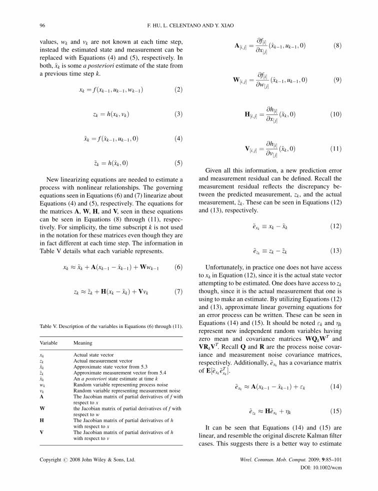
New linearizing equations are needed to estimate a
process with nonlinear relationships. The governing
equations seen in Equations (6) and (7) linearize about
Equations (4) and (5), respectively. The equations for
the matrices A, W, H, and V, seen in these equations
can be seen in Equations (8) through (11), respec-
tively. For simplicity, the time subscript k is not used
in the notation for these matrices even though they are
in fact different at each time step. The information in
Table V details what each variable represents.
xk � ~xk þ A xk�1 � xk�1ð Þ þWwk�1 ð6Þ
zk � ~zk þH xk � ~xkð Þ þ Vvk ð7Þ
A½i; j� ¼@f½i�@x½ j�
xk�1; uk�1; 0ð Þ ð8Þ
W½i; j� ¼@f½i�@w½ j�
xk�1; uk�1; 0ð Þ ð9Þ
H½i; j� ¼@h½i�@x½ j�
~xk; 0ð Þ ð10Þ
V½i; j� ¼@h½i�@v½ j�
~xk; 0ð Þ ð11Þ
Given all this information, a new prediction error
and measurement residual can be defined. Recall the
measurement residual reflects the discrepancy be-
tween the predicted measurement, zk, and the actual
measurement, ~zk. These can be seen in Equations (12)
and (13), respectively.
~exk � xk � ~xk ð12Þ
~ezk � zk � ~zk ð13Þ
Unfortunately, in practice one does not have access
to xk in Equation (12), since it is the actual state vector
attempting to be estimated. One does have access to zkthough, since it is the actual measurement that one is
using to make an estimate. By utilizing Equations (12)
and (13), approximate linear governing equations for
an error process can be written. These can be seen in
Equations (14) and (15). It should be noted "k and �krepresent new independent random variables having
zero mean and covariance matrices WQkWT and
VRkVT. Recall Q and R are the process noise covar-
iance and measurement noise covariance matrices,
respectively. Additionally, ~exk has a covariance matrix
of E½~exk~eTxk �.
~exk � A xk�1 � xk�1ð Þ þ "k ð14Þ
~ezk � H~exk þ �k ð15Þ
It can be seen that Equations (14) and (15) are
linear, and resemble the original discrete Kalman filter
cases. This suggests there is a better way to estimate
Table V. Description of the variables in Equations (6) through (11).
Variable Meaning
xk Actual state vectorzk Actual measurement vector~xk Approximate state vector from 5.3~zk Approximate measurement vector from 5.4xk An a posteriori state estimate at time kwk Random variable representing process noisevk Random variable representing measurement noiseA The Jacobian matrix of partial derivatives of f with
respect to xW the Jacobian matrix of partial derivatives of f with
respect to wH The Jacobian matrix of partial derivatives of h
with respect to xV The Jacobian matrix of partial derivatives of h
with respect to v
96 F. HU, L. CELENTANO AND Y. XIAO
Copyright # 2008 John Wiley & Sons, Ltd. Wirel. Commun. Mob. Comput. 2009; 9:85–101
DOI: 10.1002/wcm

the error prediction of Equation (15). This new esti-
mate of ~exk , called e, can be found by using Equation
(13) and a second hypothetical Kalman filter. The
Kalman filter equation used for this estimate can be
seen in
ek ¼ Kk~ezk ð16Þ
Once Equation (16) is attained, it can be used in
Equation (17) to obtain an a posteriori state estimate
for the original nonlinear process. By substituting
Equation (16) into Equation (17), the Equation (18)
is obtained. Finally, by substituting (13) into (18), the
equation which will be used for the measurement
update in the EKF is achieved. Note that ~xk and ~zkcome from Equations (2) and (3), with the appropriate
substitution for the measurement error covariance.
xk ¼ ~xk þ ek ð17Þ
xk ¼ ~xk þ Kk~ezk ð18Þ
xk ¼ ~xk þ Kk zk � ~zkð Þ ð19Þ
The complete set of EKF equations can be seen in
Tables VI and VII. The tables separately group those
equations used for time updates and those for mea-
surement updates, respectively. Additionally, the ap-
propriate subscript has been attached to the matrices
A, W, H, and V to reinforce the notion that they
are different at each time step, and therefore must
be recomputed each time. Just as with the discrete
Kalman filter, the time update Equation (1) project the
state and covariance estimates from the previous time,
k� 1, to the current time, k. An important feature of
the EKF is that Hk in the equation for the Kalman
gain, Kk, serves to correctly emphasize or magnify
only the relevant component of the measurement
information. Hk affects the Kalman gain so that it
only magnifies the portion of the residual,
zk � hðx�k ; 0Þ, that does affect the state.
5.2. ECG Modeling
With the EKF modifications made, we need to deter-
mine the equation which governs an ECG and apply it
to the filter. Produced by an ECG, the signal is
constructed by measuring electrical potentials be-
tween various points of the body using a galvan-
ometer. Figure 12 shows an example of a normal
ECG trace, which consists of a P wave, a QRS
complex and a T wave.
While this work mainly focuses on using the EKF
to recover wireless transmission errors, it can simul-
taneously be used to correct baseline wander of the
ECG. The baseline is the resting potential of the ECG
between the P, QRS, and T waves. Baseline wander
occurs whether the ECG is sent wirelessly or not, as it
is due to slipping or even moist electrodes on the body
when collecting the ECG. Since the baseline of an
ECG is used to diagnose many different cardiac
diseases, it is important to receive an accurate por-
trayal of this part of the signal. For instance, an ST
segment below the baseline implies shortage of blood
flow and oxygen.
Table VI. EKF time update equations.
x�k ¼ f xk�1; uk�1; 0ð ÞP�k ¼ AkPk�1A
Tk þWkQk�1W
Tk
Table VII. EKF measurement update equations.
Kk ¼ P�k H
Tk HkP
�k H
Tk þ VkRkV
Tk
� ��1
xk ¼ x�k þ Kk zk � h x�k ; 0� �� �
Pk ¼ I � KkHkð ÞP�k ðI � KkHkÞT þ KkRkK
Tk
Fig. 12. Example of a normal ECG trace.
ERROR-RESISTANT RFID-ASSISTED MEDICAL SENSOR NETWORKS 97
Copyright # 2008 John Wiley & Sons, Ltd. Wirel. Commun. Mob. Comput. 2009; 9:85–101
DOI: 10.1002/wcm

McSharry et al. have proposed a synthetic ECG
generator, which is based on a nonlinear dynamic
model [33]. This model has several parameters, P, Q,
R, S, and T, which come from the ECG and makes it
adaptable to many normal and abnormal signals. The
dynamic model consists of a three-dimensional state
equation, which generates a trajectory with the co-
ordinate (x, y, z). These equations may be seen in
Equations (20) through (22). The variables �,��i, and� are given in Equations (23) through (25). Note that
Equation (25) is the four quadrant arctangent of the
real parts of the elements of x and y, with the bounds
given in Equation (26). The variable ! is the angular
velocity of the trajectory as it moves around the limit
cycle. The baseline wander of the ECG signal has
been modeled with z0.
x0 ¼ �x� ! y ð20Þ
y0 ¼ �yþ !x ð21Þ
z0 ¼ �X
i2fP;Q;R;S;Tgai��iexp ���2i
2b2i
� �� z� z0ð Þ
ð22Þ
� ¼ 1�ffiffiffiffiffiffiffiffiffiffiffiffiffiffix2 þ y2
pð23Þ
��i ¼ �� �ið Þmod 2�ð Þ ð24Þ
� ¼ arctan 2 y; xð Þ ð25Þ
�� � arctan y; xð Þ � � ð26Þ
Some typical parameters for the synthetic ECG
model can be seen in Table VIII. The three-dimen-
sional trajectory which is generated consists of a
circular limit cycle which is pushed up and down
when it approaches one of the P, Q, R, S, or T points.
In fact, each of the components of the ECG waveform
has been modeled with a Gaussian function, which is
located at a specific angle. This can be seen in
Equations (20) through (22) by neglecting the baseline
wander term, z� z0, and integrating the z0 equation.The projection of the three-dimensional trajectory on
the z-axis gives a synthetic ECG signal.
5.3. Implementation
With the changes necessary for the EKF documented
and a modeling equation for the ECG completed,
these two elements simply need to be put together to
filter a noisy wireless signal. From here, this work uti-
lized the accomplishments of Sameni et al. [34] who
were able to linearize the ECG model and apply the
EKF to it in Matlab [35]. Their usage was noninvasive
fetal ECG extraction. This same work can be applied
in a completely different area, wireless data recovery.
The actual ECG data came from the Physionet.org
PhysioBank database of physiological signals [36]. A
sample of one of these normal ECG signals can be
seen in Figure 13. While the signal does have the
baseline wander typical of all ECG signals, since it
was not transmitted wirelessly there are no missing
pieces of data. Therefore, the work of Sameni et al.
had to be modified to remove data points from these
real ECG signals in order to simulate wireless data
loss.
As stated in Section 2, the error rate of wireless
transmissions is in the range of 2–10%. For this work,
it was decided to simulate the amount data lost to be
10%.
The normal ECG signal filtered by the EKF can be
seen in Figure 14. It can be seen that the final filtered
signal, seen in green, is centered at 0 and its simulated
wireless data loss has been recovered. The baseline
wander removal was performed in the signal seen in
Table VIII. Typical parameters of the synthetic ECG model.
Index (i) P Q R S T
Time (s) �0.2 �0.05 0 0.05 0.3�i (rads.) ��/3 ��/12 0 �/12 �/2ai 1.2 �5.0 30.0 �7.5 0.75bi 0.25 0.1 0.1 0.1 0.4
Fig. 13. Normal ECG signal.
98 F. HU, L. CELENTANO AND Y. XIAO
Copyright # 2008 John Wiley & Sons, Ltd. Wirel. Commun. Mob. Comput. 2009; 9:85–101
DOI: 10.1002/wcm
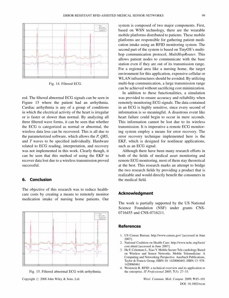
red. The filtered abnormal ECG signals can be seen in
Figure 15 where the patient had an arrhythmia.
Cardiac arrhythmia is any of a group of conditions
in which the electrical activity of the heart is irregular
or is faster or slower than normal. By analyzing all
three filtered wave forms, it can be seen that whether
the ECG is categorized as normal or abnormal, the
wireless data loss can be recovered. This is all due to
the parameterized software, which allows the P, QRS,
and T waves to be specified individually. Hardware
related to ECG reading, interpretation, and recovery
was not implemented in this work. Clearly though, it
can be seen that this method of using the EKF to
recover data lost due to a wireless transmission proved
successful.
6. Conclusion
The objective of this research was to reduce health-
care costs by creating a means to remotely monitor
medication intake of nursing home patients. Our
system is composed of two major components. First,
based on WSN technology, there are the wearable
mobile platforms distributed to patients. These mobile
platforms are responsible for gathering patient medi-
cation intake using an RFID monitoring system. The
second part of the system is based on TinyOS’s multi-
hop communication protocol, MultiHopRouter. This
allows patient nodes to communicate with the base
station even if they are out of its transmission range.
For a regional area like a nursing home, the target
environment for this application, expensive cellular or
WLAN infrastructures should be avoided. By utilizing
multi-hop communication, a large transmission range
can be achieved without sacrificing cost minimization.
In addition to these functionalities, a simulation
was provided to ensure accuracy and reliability when
remotely monitoring ECG signals. The data contained
in an ECG is highly sensitive, since every second of
information is so meaningful. A disastrous event like
heart failure could begin to occur in mere seconds.
This information cannot be lost due to its wireless
transmission. It is imperative a remote ECG monitor-
ing system employ a means for error recovery. The
error recovery technique implemented here is the
EKF, which is designed for nonlinear applications,
such as an ECG signal.
Although there have been many research efforts in
both of the fields of medical asset monitoring and
remote ECGmonitoring, most of them stay theoretical
at the best. This research marks an attempt to bridge
the two research fields by providing a product that is
realizable and would directly benefit the consumers in
the medical field.
Acknowledgment
The work is partially supported by the US National
Science Foundation (NSF) under grants CNS-
0716455 and CNS-0716211.
References
1. US Census Bureau: http://www.census.gov/ [accessed in June2007].
2. National Coalition on Health Care: http://www.nchc.org/facts/cost.shtml [accessed in June 2007].
3. Hu F, Celentano L, XiaoY.Mobile Secure Tele-cardiology Basedon Wireless and Sensor Networks. Mobile Telemedicine: AComputing and Networking Perspective. Auerbach Publications,Taylor & Francis Group, ISBN-10: 1420060465, ISBN-13: 978-1420060461
4. Weinstein R. RFID: a technical overview and its application tothe enterprise. IT Professional 2005; 7(3): 27–33.
Fig. 14. Filtered ECG.
Fig. 15. Filtered abnormal ECG with arrhythmia.
ERROR-RESISTANT RFID-ASSISTED MEDICAL SENSOR NETWORKS 99
Copyright # 2008 John Wiley & Sons, Ltd. Wirel. Commun. Mob. Comput. 2009; 9:85–101
DOI: 10.1002/wcm

5. Azrchan P, Musoff H. Fundamentals of Kalman Filtering.American Institute of Aeronautics and Astronautics, Inc.:USA 2000.
6. Xiao Y, Shen X, Sun B, Cai L. Security and privacy in RFIDand applications in telemedicine. IEEE Communications Ma-gazine Special Issue on Wireless Technology Advances andChallenges for Telemedicine, April 2006; 64–72.
7. Hu F, Kumar S, Xiao Y. Towards a secure, RFID/sensor basedtele-cardiology system. 2007 IEEE Consumer Communicationsand Networking Conference—Special Sessions Track onTelemedicine, Las Vegus, January 2007.
8. Xiao Y, Hu F. Wireless telemedicine and M-Heath. 2007 IEEEConsumer Communications and Networking Conference—Special Sessions Track on Telemedicine, Las Vegus, January2007.
9. Xiao Y, Takahashi D, Hu F. Telemedicine usage and potentials.IEEE Wireless Communications and Networks Conference2007, March 2007.
10. Hu F, Jiang M, Xiao Y. Low-cost wireless sensor networksfor remote cardiac patients monitoring applications. WirelessCommunications and Mobile Computing Journal 2007; DOI:10.1002/wcm.488
11. Hu F, Jiang M, Celentano L, Xiao Y. Robust medical ad hocsensor networks (MASN) with wavelet-based ECG data mining.Ad Hoc Networks 2007; DOI:10.1016/j.adhoc.2007.09.002
12. Xiao Y, Chen H (eds). Mobile Telemedicine: A Computing andNetworking Perspective. Auerbach Publications, Taylor &Francis Group: New York, USA, 2007; ISBN-10:1420060465, ISBN-13: 978-1420060461 (in press).
13. Alexander Q, Xiao Y, Hu F. Telemedicine for PervasiveHealthcare. Mobile Telemedicine: A Computing and Network-ing Perspective. Auerbach Publications, Taylor & FrancisGroup: New York, USA, ISBN-10: 1420060465, ISBN-13:978-1420060461
14. Biggers L, Xiao Y, Hu F. Conventional telemedicine, wirelesstelemedicine, sensor networks, and case studies. Mobile Tele-medicine: A Computing and Networking Perspective. AuerbachPublications, Taylor & Francis Group: New York, USA, ISBN-10: 1420060465, ISBN-13: 978-1420060461
15. Hu F, Lewis M, Xiao Y. Automated blood glucose managementtechniques through micro-sensors. Mobile Telemedicine: AComputing and Networking Perspective. Auerbach Publica-tions, Taylor & Francis Group: New York, USA, ISBN-10:1420060465, ISBN-13: 978-1420060461
16. Takahashi D, Xiao Y, Hu F. A Survey of security in telemedi-cine with wireless sensor networks. Mobile Telemedicine: AComputing and Networking Perspective. Auerbach Publica-tions, Taylor & Francis Group: New York, USA, ISBN-10:1420060465, ISBN-13: 978-1420060461
17. Takahashi D, Xiao Y, Hu F, Lewis M. A survey of insulin-dependent diabetes part I: therapies and Devices. InternationalJournal of Telemedicine and Applications (IJTA) (in press).
18. Chen J, Cao K, Sun Y, Xiao Y, Su X. Continuous drug infusionfor diabetes therapy: a closed-loop control system design.EURASIP Journal on Wireless Communications and Network-ing, special issue on Wireless Telemedicine and Applications(in press).
19. Xiao Y, Yu S, Wu K, Ni Q, Janecek C, Nordstad J. Radiofrequency identification: technologies, applications, and re-search issues. Wireless Communications and Mobile Comput-ing (WCMC) Journal 2007; 7(4): 457–472.
20. Su X, Xiao Y. Analysis of energy consumption for multipleobject identification system with active RFID Tags.Wireless Communications and Mobile Computing (WCMC)(in press). A conference version of this paper can be foundin: http://ieeexplore.ieee.org/iel5/4204175/4204176/04204910.pdf’’, 2008.
21. Wang S, ChenW, Ong C, Liu L, Chuang Y. RFID application inhospitals: a case study on a demonstration RFID project in a
Taiwan hospital. In Proceedings of the 39th Annual HawaiiInternational Conference on System Sciences, (HICSS’06), Vol.8, 4–7 January 2006; 184a–184a.
22. Exavera Technologies. eShepherd overview. http://www.exavera. com/healthcare/eshepherd.php [downloaded 22 August2007].
23. En-Vision America. ScripTalk. http://www.envisionamerica.com/scriptalk/scriptalk.php [downloaded 22 August 2007].
24. Murthy C, Manoj B. Ad Hoc Wireless Networks. Prentice-HallPTR: Englewood cliffs, New Jersey, USA, 2004.
25. Tse D, Viswanath P. Fundamentals of Wireless Communica-tion. Cambridge University Press: England, June 27, 2005.
26. Welch G, Bishop G. An Introduction to the Kalman Filter.Available from http://www.cs.unc.edu/�welch/kalman/kalma-nIntro.html
27. TinyOS. Multihop Routing. http://www.tinyos.net/tinyos-1.x/doc/multihop/multihop_routing.html
28. SkyeTek. SkyeModule M1-mini. http://www.skyetek.com/SkyeModuleM1mini/tabid/338/Default.aspx
29. MySQL. WhyMySQL?. http://dev.mysql.com/doc/refman/5.1/en/what-is-mysql.html
30. Crossbow Technology, Inc. Discontinued Products. http://www.xbow.com/Products/wDiscontinuedPage2.aspx
31. Crossbow Technology, Inc. TinyOS Getting Started Guide. RevA, October, 2003. http://www.qlimu.com/doc/TinyOS%20Get-ting%20Started%20Guide%207430-0022-03_A.pdf
32. Levis P, Madden S, Gay D, Polastre J, Szewczyk R, Woo A,Brewer E, Culler D. The emergence of networking abstractionsand techniques in TinyOS. In Proceedings of the FirstSymposium on Networked Systems Design and Implementation,USENIX Association, 2004; 1–14.
33. McSharry PE, Clifford GD, Tarassenko L, Smith LA. Adynamical model for generating synthetic electrocardiogramsignals. IEEE Transactions on Biomedical Engineering 2003;50(3): 289–294.
34. Sameni R, Shamsollahi MB, Jutten C, Babaie-Zade M. Filter-ing noisy ECG signals using the extended Kalman filter basedon a modified dynamic ECG model. Computers in Cardiology2005; 1017–1020.
35. MATLAB Product Page. http://www.mathworks.com/products/matlab/
36. PhysioNet ECG database. Available from http://www.physionet.org/physiobank/database/nsrdb/
Authors’ Biographies
Dr Fei Hu is an associate professor
in the Department of Computer
Engineering at RIT (Rochester In-
stitute of Technology), New York,
USA. His research interests are
wireless networks, wireless secur-
ity, and their applications in Bio-
Medicine. His research has been
supported by NSF, Cisco, Sprint, and other sources.
He obtained his first Ph.D. degree at Shanghai Tongji
University, China in 1999, and second Ph.D. degree at
Clarkson University, USA in 2002, all in the field of
Computer Engineering. He has published over 100
journal/conference papers and book (chapters). He is
also the Editor for over five international journals.
100 F. HU, L. CELENTANO AND Y. XIAO
Copyright # 2008 John Wiley & Sons, Ltd. Wirel. Commun. Mob. Comput. 2009; 9:85–101
DOI: 10.1002/wcm

Laura Celentano is a graduate
student of Computer Engineering
Department, Rochester Institute of
Technology Rochester.
Yang Xiao worked in industry as a
Medium Access Control (MAC)
architect involving the IEEE
802.11 standard enhancement
work before he joined the Depart-
ment of Computer Science at The
University of Memphis in 2002. Dr
Xiao is currently with the Depart-
ment of Computer Science at the
University of Alabama. He was a voting member of
IEEE 802.11 Working Group from 2001 to 2004. He
is an IEEE Senior Member. He is a member of
American Telemedicine Association. He currently
serves as Editor-in-Chief for International Journal
of Security and Networks (IJSN), International Jour-
nal of Sensor Networks (IJSNet), and International
Journal of Telemedicine and Applications (IJTA). He
serves as a referee/reviewer for many funding agen-
cies, as well as a panelist for NSF and a member of
Canada Foundation for Innovation (CFI)’s Telecom-
munications expert committee. He serves as TPC for
more than 100 conferences such as INFOCOM,
ICDCS, MOBIHOC, ICC, GLOBECOM, WCNC,
etc. He serves as an Associate Editor for several
journals, for example, IEEE Transactions on Vehicu-
lar Technology. His research areas are security, tele-
medicine, sensor networks, and wireless networks. He
has published more than 200 papers in major journals
(more than 50 in various IEEE journals/magazines),
refereed conference proceedings, book chapters
related to these research areas. Dr Xiao’s research
has been supported by the US National Science Foun-
dation (NSF).
ERROR-RESISTANT RFID-ASSISTED MEDICAL SENSOR NETWORKS 101
Copyright # 2008 John Wiley & Sons, Ltd. Wirel. Commun. Mob. Comput. 2009; 9:85–101
DOI: 10.1002/wcm