Errata Central (160223) - NCDOI · Errata Central (160223) Following ... The use of empirical...
19
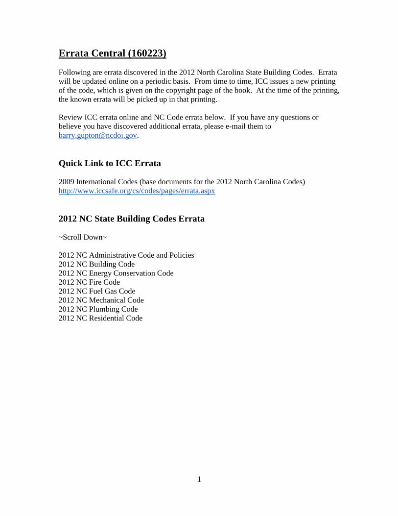
1 Errata Central (160223) Following are errata discovered in the 2012 North Carolina State Building Codes. Errata will be updated online on a periodic basis. From time to time, ICC issues a new printing of the code, which is given on the copyright page of the book. At the time of the printing, the known errata will be picked up in that printing. Review ICC errata online and NC Code errata below. If you have any questions or believe you have discovered additional errata, please e-mail them to [email protected]. Quick Link to ICC Errata 2009 International Codes (base documents for the 2012 North Carolina Codes) http://www.iccsafe.org/cs/codes/pages/errata.aspx 2012 NC State Building Codes Errata ~Scroll Down~ 2012 NC Administrative Code and Policies 2012 NC Building Code 2012 NC Energy Conservation Code 2012 NC Fire Code 2012 NC Fuel Gas Code 2012 NC Mechanical Code 2012 NC Plumbing Code 2012 NC Residential Code
Transcript of Errata Central (160223) - NCDOI · Errata Central (160223) Following ... The use of empirical...
1
Errata Central (160223)
Following are errata discovered in the 2012 North Carolina State Building Codes. Errata
will be updated online on a periodic basis. From time to time, ICC issues a new printing
of the code, which is given on the copyright page of the book. At the time of the printing,
the known errata will be picked up in that printing.
Review ICC errata online and NC Code errata below. If you have any questions or
believe you have discovered additional errata, please e-mail them to
Quick Link to ICC Errata
2009 International Codes (base documents for the 2012 North Carolina Codes)
http://www.iccsafe.org/cs/codes/pages/errata.aspx
2012 NC State Building Codes Errata
~Scroll Down~
2012 NC Administrative Code and Policies
2012 NC Building Code
2012 NC Energy Conservation Code
2012 NC Fire Code
2012 NC Fuel Gas Code
2012 NC Mechanical Code
2012 NC Plumbing Code
2012 NC Residential Code

2
2012 NC Administrative Code and Policies
On page 5-6, Section 107.3
107.3 Approval required. Work shall not be done beyond the point indicated in each
successive inspection without first obtaining the approval of the code enforcement
official. The code enforcement official, upon notification, shall make the requested
inspections and shall either indicate the portion of the construction that is satisfactory as
completed, or shall notify the permit holder or an agent of the permit holder that the work
fails to comply with the technical codes. The code enforcement official shall identify
code violations and when requested shall identify the specific sections of the technical
codes. Any work that does not comply shall be corrected and shall not be covered or
concealed until authorized by the code enforcement official.
3
2012 NC Building Code
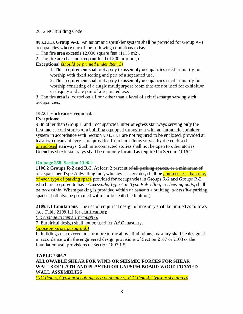
903.2.1.3. Group A-3. An automatic sprinkler system shall be provided for Group A-3
occupancies where one of the following conditions exists:
1. The fire area exceeds 12,000 square feet (1115 m2).
2. The fire area has an occupant load of 300 or more; or
Exceptions: (should be printed under Item 2)
1. This requirement shall not apply to assembly occupancies used primarily for
worship with fixed seating and part of a separated use.
2. This requirement shall not apply to assembly occupancies used primarily for
worship consisting of a single multipurpose room that are not used for exhibition
or display and are part of a separated use.
3. The fire area is located on a floor other than a level of exit discharge serving such
occupancies.
1022.1 Enclosures required.
Exceptions:
9. In other than Group H and I occupancies, interior egress stairways serving only the
first and second stories of a building equipped throughout with an automatic sprinkler
system in accordance with Section 903.3.1.1 are not required to be enclosed, provided at
least two means of egress are provided from both floors served by the enclosed
unenclosed stairways. Such interconnected stories shall not be open to other stories.
Unenclosed exit stairways shall be remotely located as required in Section 1015.2.
On page 258, Section 1106.2
1106.2 Groups R-2 and R-3. At least 2 percent of all parking spaces, or a minimum of
one space per Type A dwelling unit, whichever is greater, shall be , but not less than one,
of each type of parking space provided for occupancies in Groups R-2 and Groups R-3,
which are required to have Accessible, Type A or Type B dwelling or sleeping units, shall
be accessible. Where parking is provided within or beneath a building, accessible parking
spaces shall also be provided within or beneath the building.
2109.1.1 Limitations. The use of empirical design of masonry shall be limited as follows
(see Table 2109.1.1 for clarification):
(no change to items 1 through 6)
7. Empirical design shall not be used for AAC masonry.
(space separate paragraph)
In buildings that exceed one or more of the above limitations, masonry shall be designed
in accordance with the engineered design provisions of Section 2107 or 2108 or the
foundation wall provisions of Section 1807.1.5.
TABLE 2306.7
ALLOWABLE SHEAR FOR WIND OR SEISMIC FORCES FOR SHEAR
WALLS OF LATH AND PLASTER OR GYPSUM BOARD WOOD FRAMED
WALL ASSEMBLIES
(NC Item 5, Gypsum sheathing is a duplicate of ICC Item 4, Gypsum sheathing)

4
On page 476, Table 2308.9.3(2)
TABLE 2308.9.3(2)
EXPOSED PLYWOOD PANEL SIDING
MINIMUM THICKNESS a
(inch)
MINIMUM NUMBER OF PLIES STUD SPACING
(inches)
Plywood siding applied directly to studs
or over sheathing
3/8 3 16 b
1/2 4 24
For SI: 1 inch = 25.4 mm.
a. Thickness of grooved panels is measured at bottom of grooves.
b. Spans are permitted to be 24 inches if plywood siding applied with face grain
perpendicular to studs or over one of the following: (1) 1-inch board sheathing, (2) 7/16 -
inch wood structural panel sheathing or (3) 3/8-inch wood structural panel sheathing with
strength axis (which is the long direction of the panel unless otherwise marked) of
sheathing perpendicular to studs.
(was omitted from publication)

5
2012 NC Energy Conservation Code
On page 16, Table 402.1.3
- Change the highlighted values below
CZ Fenestration Skylight Ceiling Frame
Wall
Mass
Wall
Floor Basement Crawl
3 0.35 0.65 0.035 0.082 0.141 0.047 0.059 0.136
4 0.35 0.60 0.030 0.077 0.141 0.047 0.059 0.065
5 0.35 0.60 0.030 0.061 0.082 0.033 0.059 0.065
On page 16, Section 402.2.3, Exception 2
2. Full size doors that are part of the building thermal envelope and provide a
passageway to unconditioned spaces shall meet the requirements of exterior doors in
Section 403.2.4 402.3.4.
On page 22, Table 405.5.2(1)
- Under BUILDING COMPONENT Air exchange rate, STANDARD REFERENCE
DESIGN
Change Specific leakage area (SLA)d = 0.00021 or 3 ACH50
To Specific leakage area (SLA)d = 0.00028 or 5 ACH50
On Page 22 and 23, Table 405.5.2(1)
TABLE 405.5.2(1)
SPECIFICATIONS FOR THE STANDARD REFERENCE AND PROPOSED
DESIGNS
BUILDING
COMPONENT
STANDARD REFERENCE DESIGN PROPOSED DESIGN
Fenestrationa,b
Total areab,c =
(a) The proposed fenestration area;
where proposed fenestration area is less
than 15% of the conditioned floor area.
(b) 15% of the conditioned floor area;
where the proposed fenestration area is
15% or more of the conditioned floor
area.
Orientation: equally distributed to four
cardinal compass orientations (N, E, S
& W).
U-factor: from Table 402.1.3
SHGC: from Table 402.1.1
Interior shade fraction:
Summer (all hours when cooling is
As proposed
As proposed
As proposed
As proposed
Same as standard
reference designd
As proposed

6
required) = 0.90
Winter (all hours when heating is
required) = 0.90c
External shading: none
TABLE 405.5.2(1)—continued SPECIFICATIONS FOR THE STANDARD REFERENCE AND PROPOSED
DESIGNS
BUILDING COMPONENT
STANDARD REFERENCE DESIGN
PROPOSED DESIGN
Air exchange rate Specific leakage area (SLA)dd =
0.00021 0.00028 or 3 5 ACH50.
For residences that are not
tested, the same as the
standard reference design.
Heating systems g,h,i,j
As proposed
Capacity: sized in accordance with
the North Carolina Mechanical
Code and North Carolina
Residential Code.
Fuel type: same as proposed design
As proposed
Cooling systemsh,
i, j, k
As proposed
Capacity: sized in accordance with
the North Carolina Mechanical
Code and North Carolina
Residential Code.
As proposed
Service water
heating h, i,k, l
As proposed
Fuel type: use: same as proposed
design
As proposed
gal/day = 30 + (10 x Nbr)
Thermal
distribution
systems
A thermal distribution system
efficiency (DSE) of 0.88 shall be
applied to both the heating and cooling
system efficiencies for all systems
other than tested duct systems. Duct
insulation: From Section 403.2.1. For
tested duct systems, the leakage rate
shall be the applicable maximum rate
from Section 403.2.2.
As tested or as specified in
Table
405.5.2(2) if not tested

7
Lighting kWh/yr = (455 + 0.80 * CFA) +
ΔkWh/yr
where:
ΔkWh/yr = [29.5 – 0.5189*CFA *50
75% –295.12*50 75% + 0.0519*CFA]
Internal gains in the Standard
Reference Design shall
be reduced by 90% of the impact from
efficient lighting,
calculated in Btu/day using the
following equation:
ΔIGlighting = - 0.90 * ΔkWh/yr * 106 /
293 / 365
kWh/yr = (455 + 0.80 *
CFA) + ΔkWh/yr
where:
ΔkWh/yr = [29.5 –
0.5189*CFA*FL% –
295.12*FL% +
0.0519*CFA]
FL% = the ratio of
Qualifying Light Fixtures
to all light fixtures in
Qualifying Light Fixture
Locations.
The Proposed Design shall
not have FL% more than
50 75% from CFL.
Internal gains in the
Proposed Design shall be
reduced by 90% of the
impact from efficient
lighting, calculated in
Btu/day using the
following
equation:
ΔIGlighting =0.90*ΔkWh/yr
* 106/293/ 365
On page 29, Table 502.2(1) TABLE 502.2(1)
BUILDING ENVELOPE REQUIREMENTS – OPAQUE ASSEMBLIES
Climate Zone 3 4 5
All Other Group R All Other Group R All Other Group R
Roofs
Insulation entirely above deck
R - 25 ci
R-25 ci R - 30 ci R-30 ci R - 30 ci R-30 ci
Metal buildings (with
R-5 thermal blocks)a,b R-10 + R-19
FC
R-10 + R-19
FC
R-19 + R-11
Ls
R-19 + R-11
Ls
R-19 + R-11
Ls
R-19 + R-11
Ls
Attic and other - wood
framingf R-38 R-38 R-42 R-42 R-42 R-42
Attic and other - steel framingf
R-38 R-38 R-49 R-49 R-49 R-49

8
Walls, Above Grade
Mass R-7.6 ci R-9.5 ci R-9.5 ci R-11.4 ci R-11.4 ci R-15 ci
Metal buildingb R-0+R-13 ci R-0 + R-19 ci R-0 + R-15.8
ci
R-0 + R-19 ci R-0 + R-19 ci R-0 + R-19 ci
Metal framed R-13 + 7.5 ci R- 13 +
R-7.5 ci
R-13 + R-10 ci R-13 +
R-12.5 ci
R-13 +
R-12.5 ci
R- 13 +
R-15 ci
Wood framed and
other R-13 + R-3.8
ci
R-19, R-13+
R-5, or R-15 +
R-3g
R-13 + R-7.5
ci
R-19, R-13+
R-5, or R-15 +
R-3g
R-13 + R-10 ci R-19, R-13+
R-5, or R-15 +
R-3g
Walls, Below Grade
Below-grade wallc R-7.5 ci R-7.5 ci R-7.5 ci R-10 ci R-7.5 ci R-10 ci
Floors
Mass R-12.5 ci R-12.5 ci R-14.6 ci R-16.7 ci R-14.6 ci R-16.7 ci
Joist / Framing R-30e R-30e R-38 R-38 R-38 R-38
Slab-on-Grade Floorsd
Unheated slabs NR
R-10 for 24 in. R-15 for 24 in. R-15 for 24 in. R-15 for 24 in. R-20 for 24 in.
Heated slabs R-15 for 24 in. R-15 for 24 in. R-20 for 24 in. R-20 for 48
in.
R-20 for 48
in.
R-20 for 48
in.
Opaque Doors
Swinging U – 0.70 U – 0.50 U – 0.50 U – 0.50 U – 0.50 U – 0.50
Roll-up or sliding U - 0.50 U - 0.50 U - 0.50 U - 0.50 U - 0.50 U - 0.50
For SI: 1 inch = 25.4 mm. CI = Continuous insulation. FC = Filled Cavity. LS = Liner System. NR = No requirement.
a. When using R-value compliance method, a thermal spacer block is required, otherwise use the U-factor compliance method. [see
Tables 502.1.2 and 502.2(2)]. b. Assembly descriptions can be found in Table 502.2(2).
c. R-5.7 ci is allowed to be substituted with concrete block walls complying with ASTM C 90, ungrouted or partially grouted at 32
inches or less on center vertically and 48 inches or less on center horizontally, with ungrouted cores filled with material having a maximum thermal conductivity of 0.44 Btu-in./h-f2 F.
d. For monolithic slabs, insulation shall be applied from the inspection gap downward to the bottom of the footing. For floating slabs,
insulation shall extend to the bottom of the foundation wall or 24 inches, whichever is less. (See Appendix 1.C) e. Steel floor joist systems shall to be R-38.
f. R-30 shall be deemed to satisfy the requirement for R-38 wherever the full height of uncompressed R-30 insulation extends over the
wall top plate at the eaves. Similarly, R-38 shall be deemed to satisfy the requirement for R-42 or R-49 wherever the full height of uncompressed R-38 insulation extends over the wall top plate at the eaves.
On page 30, Table 502.2(2) TABLE 502.2(2)
BUILDING ENVELOPE REQUIREMENTS–OPAQUE ASSEMBLIES ROOFS DESCRIPTION
R-10 + R-19FC
Filled cavity fiberglass insulation.
A continuous vapor barrier is installed below the purlins and uninterrupted by framing members. Both
layers of uncompressed, unfaced fiberglass insulation rest on top of the vapor barrier and are installed
parallel, between the purlins. A minimum R-5 thermal spacer block is placed above the purlin/batt, and the roof
deck is secured to the purlins. Drawings of typical details are shown in Appendix 2.1. R-19 + R11 Ls
Liner System with minimum R-3.5 thermal spacer block.
A continuous membrane is installed below the purlins and uninterrupted by framing members.
Uncompressed, unfaced insulation rests on top of the membrane between the purlins. Drawings of typical details are shown in Appendix 2.1.
WALLS
R-0 + R-13 ci R-0 + R-19 ci
The second rated R-value is for continuous rigid insulation installed between the metal wall panel and steel framing, or on the interior of the steel framing. Drawings of typical details are shown in
Appendix 2.1.
On page 55, Table 506.2.1(5) 506.2.1(6)
CHILLERS - EFFICIENCY REQUIREMENTS

9
On page 55, Table 506.2.1(6) 506.2.1(7)
ABSORPTION CHILLERS - EFFICIENCY REQUIREMENTS
On page 57, Section 507.5.2
507.5.2 Thermal blocks. The standard reference design and proposed design shall be
analyzed using identical thermal blocks as required in Section 507.5.1.1 507.5.2.1,
507.2.2 or 507.5.2.3.
On page 94, Figure
APPENDIX 2.2: COMMERCIAL BUILDING OPAQUE ASSEMBLIES
Table 502.2(2) Roofs.
R-3.5 R-5 THERMAL SPACER BLOCK
On page 95, Figure
Table 502.2(2) Roofs.
R-3.5 R-5 THERMAL SPACER BLOCK
On page 101, Table 4B
- Change the highlighted values below
CZ Fenestration Skylight Ceiling Frame
Wall Mass
Wall Floor Basement Crawl
3 0.32 0.65 0.030 0.061 0.141 0.047 0.059 0.065
4 0.32 0.60 0.030 0.061 0.141 0.047 0.059 0.065
5 0.32 0.60 0.030 0.061 0.082 0.033 0.059 0.055
On page 104, Form 4D.2
Air sealing: Testing option (Section 402.4.2.2)
Sample Worksheet for Alternative Residential Energy Code for Higher Efficiency
For Test Criteria 1 above, the report shall be produced in the following manner:
Perform the blower door test and record the CFM50___________. Calculate the total
square feet of surface area for the building thermal envelope, all floors, ceilings, and
walls (this includes windows and doors) and record the area______________. Divide
CFM50 by the total square feet and record the result below. If the result is less than or
equal to [0.30 0.24 CFM50/SFSA] the envelope tightness is acceptable; or
For Test Criteria 2 above, the report shall be produced in the following manner:
Perform a blower door test and record the CFM50___________. Multiply the CFM50 by
60 minutes to create CFHour50 and record ______________. Then calculate the total
conditioned volume of the home and record_________________. Divide the CFH50 by
the total volume and record the result below. If the result is less than or equal to [5 4
ACH50] the envelope tightness is acceptable.

10
2012 NC Fire Code
SECTION 108
BOARD OF APPEALS
See the provisions of the North Carolina Administrative Code and Policies and
applicable North Carolina General Statutes.
108.1 Board of appeals established. In order to hear and decide appeals of orders,
decisions or determinations made by the fire code official relative to the application and
interpretation
of this code, there shall be and is hereby created a board of appeals. The board of appeals
shall be appointed by the governing body and shall hold office at its pleasure. The fire
code official
shall be an ex officio member of said board but shall have no vote on any matter before
the board. The board shall adopt rules of procedure for conducting its business, and shall
render
all decisions and findings in writing to the appellant with a
duplicate copy to the fire code official.
108.2 Limitations on authority. An application for appeal shall be based on a claim that
the intent of this code or the rules legally adopted hereunder have been incorrectly
interpreted,
the provisions of this code do not fully apply, or an equivalent method of protection or
safety is proposed. The board shall have no authority to waive requirements of this code.
108.3 Qualifications. The board of appeals shall consist of members who are qualified
by experience and training to pass on matters pertaining to hazards of fire, explosions,
hazardous conditions or fire protection systems and are not employees of the jurisdiction.
202
R-3. Child care facilities that provide accommodations for five eight or fewer persons
with no more than five for a preschool of any age for less than 24 hours.
1002
Suite. A group of rooms within a Group I-2 occupancy that comply with the
requirements of Sections 1014.1.1 1014.2.3 – 1014.2.7.
1008.1.9.3 Locks and latches.
2.3. The use of a key-operated device is revocable by the building official for violations
of this Section 1008.1.9.3.
1009.11. Ship Ladders.
Ship ladders shall have a minimum tread depth of 5 inches (127mm). The tread shall be
projected such that the total of the tread depth plus the nosing projection is not less than 8
½ inches (216mm). The minimum riser height shall be 9 ½ inches (241mm) pitch of 60
to 75 degrees (1.05 to 1.31 rad), maximum width of 30 inches (762 mm) to the outside of

11
the handrails, minimum tread depth of 5 inches (127 mm), riser height of 9 ½ inches
(241.3mm) to 12 inches (304.8mm), 1 ¼ inch (31.75 mm) pipe handrail. The vertical rise
between floor levels or landings shall not exceed 20 feet (6096 mm).
1013.3 Opening limitations. Required guards shall not have openings which allow
passage of a sphere 4 inches (102 mm) in diameter from the walking surface to the
required guard height. A bottom rail or curb shall be provided that will reject the passage
of a 2 inch-diameter (51 mm) sphere.
1013.5 Mechanical equipment. Guards shall be provided where appliances, equipment,
fans, roof hatch openings or other components that require service are located within 10 6
feet (3048 1829 mm) of a roof edge or open side of a walking surface and such edge or
open side is located more than 30 inches (762mm) above the floor, roof or grade
below…..
1018.2 Corridor width.
Exceptions: (no errata to Exceptions 1, 3, 4)
2. Thirty six inches (914mm) – In other than Groups I-1, I-2 and I-3 with a required
occupant capacity less than 50.
5. Seventy-two inches (1829 mm) – In corridors and areas serving gurney traffic in
occupancies where patients receive outpatient medical care, which causes the patient to
be not capable of self-preservation and resident areas of Group I-1 and I-2.
6. Ninety-six inches (2439 mm) – In Group I-2 in patient areas and in areas where
required for bed movement.
Table 1018.1. Add Table 1018.1 including additional footnotes d, e, and f.
Table 1021.2. – Stories with one exit
Add the following footnote f that applies to Group R occupancies:

12
f. Group R-4 adult and child care facilities shall have two exits or the rooms where the
occupants receive care shall be located on the level of exit discharge and each of these
rooms shall have an exit door directly to the exterior.
1022.1 Exit enclosures. Add exceptions 8 and 9.
8. In other than Group H and I occupancies, a maximum of 50 percent of egress
stairways serving one adjacent floor are not required to be enclosed, provided at least two
means of egress are provided from both floors served by the unenclosed stairways. Any
two such interconnected floors shall not be open to other floors. Unenclosed exit
stairways shall be remotely located as required in Section 1015.2.
9. In other than Group H and I occupancies, interior egress stairways serving only the
first and second stories of a building equipped throughout with an automatic sprinkler
system in accordance with Section 903.3.1.1 are not required to be enclosed, provided at
least two means of egress are provided from both floors served by the enclosed stairways.
Such interconnected stories shall not be open to other stories. Unenclosed exit stairways
shall be remotely located as required in Section 1015.2
Section 1029 Emergency Escape and Rescue
Section 1029.1 General. In addition to the means of egress required by this chapter,
provisions shall be made for emergency escape and rescue in Group E classrooms, Group
R and I-1 occupancies. Basements……..(remainder of paragraph is unchanged)
Exceptions: Add exception 8.
8. In Group E where the room or space complies with the following:
8.1. Doors open directly to a corridor with exit access in one direction and provide access
through adjacent classrooms or directly to a separate smoke compartment with exit access
in the other direction;
8.2. The compartments are separated by smoke barriers having a 1-hour fire resistance
rating with self-closing or automatic closing doors;
8.3. The length of travel to exits along such paths shall not exceed 150 feet (45m);
8.4. Each communicating door shall be identified; and
8.5. No locking device shall be allowed on the communicating doors.
Section 1029.3 Maximum height from floor. Emergency escape and rescue openings
shall have the bottom of the clear opening not greater than 44 inches (1118 mm)
measured from the floor. For classrooms serving children grade 5 and lower, the bottom
of the clear opening shall be not more than 32 inches (810 mm) measured from the floor.

13
2012 NC Fuel Gas Code

14
2012 NC Mechanical Code

15
2012 NC Plumbing Code
On page 20, TABLE 403.1 - continued
MINIMUM NUMBER OF REQUIRED PLUMBING FIXTURES. Factory and Industrial (See OSHA 29 CFR paragraph 1910.14.1 1910.141)
On page 25, Section 410.1
410.1 Approval. Drinking fountains shall conform to ASME A112.19.1M, ASME
A112.19.2M or ASME A112.19.9M and water coolers shall conform to ARI 1010.
Drinking fountains and water coolers shall conform to NSF 61, Section 9. Where water is
served in restaurants, night clubs, taverns, or bars, drinking fountains shall not be
required. In other occupancies, where drinking fountains are required, water coolers or
bottled water dispensers shall be permitted to be substituted for not more than 50 percent
of the required drinking fountains.
On page 59, TABLE 709.1
DRAINAGE FIXTURE UNITS FOR FIXTURES AND GROUPS
Shower (based on the total flow rate through showerheads and body sprays)
5.7 gpm or less 2 1 ½ 2
On page 69, Section 909.1, 909.3
909.1 Wet vent permitted. Any combination of fixtures within two bathroom groups
located on the same floor level is permitted to be vented by a horizontal wet vent. The
wet vent shall be considered the vent for the fixtures and shall extend from the
connection of the dry vent along the direction of the flow in the drain pipe to the most
downstream fixture drain connection to the horizontal branch drain. Each wet-vented
fixture drain shall connect independently to the horizontal wet vent. Only the fixtures
within the bathroom groups shall connect to the wet-vented horizontal branch drain. A
residential clothes washer drain line shall not be used as a wet vent.
909.3 Size. The wet vent serving the wet vent shall be sized based on the largest required
diameter of pipe within the wet-vent system served by the dry vent. The wet vent shall be
of a minimum size as specified in Table 909.3, based on the fixture unit discharge to the
wet vent.
On page 70, TABLE 912.3
SIZE OF COMBINATION DRAIN AND VENT PIPE
Deleted.

16
2012 NC Residential Code
On page 1, Section R101.2
R101.2 Scope (change Section reference in Item 2, no other changes)
2. The building is supported on a wood foundation of a minimum 2x6 or 3x4 mud sill of
approved wood in accordance with Section 323 R317: and
On page 32, Table R301.7
ALLOWABLE DEFLECTION OF STRUCTURAL MEMBERS
Floors and plastered ceilings L/360f
On page 46, Section R313.1, Exception 1
1. Townhouses constructed with a common 2-hour fire-resistance-rated wall assembly
tested in accordance with ASTM E 119 or UL 263 provided such walls do not contain
plumbing or mechanical equipment, ducts or vents in the cavity of the common wall. The
wall shall be rated for fire exposure from both sides and shall extend to and be tight
against exterior walls and the underside of the roof sheathing. Electrical installations shall
be installed in accordance with the North Carolina Electrical Code. Penetrations for
electrical outlet boxes shall be in accordance with Section R302.4.
On page 46, Section R313.1.1
R313.1.1 Design and installation. Automatic residential fire sprinkler systems for
townhouses shall be designed and installed in accordance with Appendix P, Section
P2904.
On page 47, Section R315
R315.1 Carbon monoxide alarms. In new construction, one-and two-family dwellings
and townhouses within which fuel-fired appliances or fireplaces are installed or that have
attached garages shall be provided with an approved carbon monoxide alarm installed
outside of each separate sleeping area in the immediate vicinity of the bedroom(s) as
directed by the alarm manufacturer.
R315.2 Where required-existing dwellings. For existing dwellings, where interior
alterations, repairs, fuel-fired appliance replacements, or additions requiring a building
permit occurs, or where one or more sleeping rooms are added or created, or where fuel-
fired appliances or fireplaces are added or replaced, carbon monoxide alarms shall be
provided in accordance with Section 315.1.
Exception:
Work involving the exterior surfaces of dwellings, such as the replacement of roofing or
siding, or the addition or replacement of windows or doors, or the addition of a porch or
deck, or the installation of a fuel-fire appliance that cannot introduce carbon monoxide to
the interior of the dwelling, are exempt from the requirements of this section.
R315.3 Alarm requirements. The required carbon monoxide alarms shall be audible in
all bedrooms over background noise levels with all intervening doors closed. Single
station carbon monoxide alarms shall be listed as complying with UL 2034 and shall be

17
installed in accordance with this code and the manufacturer’s installation instructions.
Battery powered, plug-in, or hard-wired alarms are acceptable for use.
On page 51, Section R318.4.3
R318.4.3 Slab on grade (non- structural). Foam plastic shall be installed along the
vertical edge and underneath the slab as specified in Section R318.5.5 R318.4.5.
On page 51, Section R318.4.5.1
R318.4.5.1 Inspection and treatment gaps. Foam plastic in contact with the ground
shall not be continuous to the bottom of the weather-resistant siding. A clear and
unobstructed 2-inch (51 mm) minimum inspection gap shall be maintained from the
bottom of the weather-resistant siding to the top of any foam plastic. A minimum 4-inch
(102 mm) treatment gap shall be provided beginning not more than 6 inches (152 mm)
below grade. The top and bottom edges of the foam plastic installed between the
inspection gap and the treatment gap shall be cut at a 45-degree (0.79 rad) angle. See
Appendix 0.
Exception: For ICF foundations see Section R404.4.7.2 R404.1.2.3.6.1.
On page 85, Heading
- SECTION R408 UNDER FLOOR SPACE WALL VENTED CRAWL
SPACES
On page 87, Section R409.8.1.1
R409.8.1.1 Foam plastic termite inspection gap. For outside walls Section R318.4
governs applications. When expanded polystyrene, polyisocyanurate, or other foam
plastic insulation is installed on the inside surface of the exterior foundation walls,
provisions in Sections R409.8.1.1.1 through R409.8.1.1.2 below apply.
On page 87, Section R409.8.1.1.2
R409.8.1.1.2 Concrete floor surfaced crawl spaces.
Provide a clear and unobstructed 3-inch minimum termite inspection gap between the top
of the foam plastic wall insulation and the bottom of the wood sill. Provide a continuous
3-inch minimum clearance gap between the bottom edge of the foam plastic wall
insulation and the earth floor surface. Refer to Section N1102.2.9 to determine maximum
allowances for insulation gaps.
On page 87, Section R409.8.1.2
R409.8.1.2 Porous insulation material.
When fiberglass, rockwool, cellulose or other porous insulation materials are installed on
the inside wall surface of a closed crawl space, provide a clear and unobstructed 3-inch
minimum termite inspection gap between the top of the porous wall insulation and the
bottom of the wood sill.
To reduce wicking potential, porous insulation ground contact is not allowed in earth
floored or concrete surfaces crawl spaces. Provide a continuous 3-inch minimum wicking
gap between the bottom edge of the porous wall insulation and the earth or concrete floor

18
surface. Refer to Section N1102.2.9 to determine maximum allowances for insulation
gaps.
On page 130, Table R603.3(1)
FLOOR FRAMING
Rim joist to top plate (toe-nailed) 2½” x 0.113” (3d box)c 6” o.c. 4” o.c.
On page 344, Section R703.7.3.2
R703.7.3.2 The allowable span shall not exceed 18 feet 3 inches (5562 mm) and shall
be constructed to comply with Figure R703.7.3.2 and the following:
On page 405, Section R807
R807.1 Attic access. An attic access opening shall be provided to attic areas that exceed
400 square feet (37.16 m2) and have a vertical height of 60 inches (1524 mm) or greater.
The net clear opening shall not be less than 20 inches by 30 inches (508 mm by 762 mm)
and shall be located in a hallway or other readily accessible location. A 30-inch (762 mm)
minimum unobstructed headroom in the attic space shall be provided at some point above
the access opening. See the North Carolina Mechanical Code for access requirements
where mechanical equipment is located in attics.
On page 432, Table N1102.1
- Change the highlighted values below
CZ Fenest
ration Sky
Lightb Glazed
Fenestb,e
Ceilingk Frame
Walle Mass
Walli Floor Base
mentc Slabd Crawl
3 0.35 0.65 0.30 30 13 5/10 19 10/13 f 0 5/13
4 0.35 0.60 0.30 38 or 30
cont. j
15,
13 + 2.5h 5/10 19 10/13 10d 10/13
5 0.35 0.60 NR 38 or 30
cont. j 19, 13 + 5,
15 + 3e,h 13/17 30g 10/13 10d 10/13
On page 433, Table N1102.1.2
- Change the highlighted values below
CZ Fenestration Skylight Ceiling Frame
Wall Mass
Wall Floor Basement Crawl
3 0.35 0.65 0.035 0.082 0.141 0.047 0.059 0.136
4 0.35 0.60 0.030 0.077 0.141 0.047 0.059 0.065
5 0.35 0.60 0.030 0.061 0.082 0.033 0.059 0.065
On page 889, Appendix E-4 Table E-4B
- Change the highlighted values below
CZ Fenestration Skylight Ceiling Frame
Wall Mass
Wall Floor Basement Crawl
3 0.32 0.65 0.030 0.061 0.141 0.047 0.059 0.065
4 0.32 0.60 0.030 0.061 0.141 0.047 0.059 0.065

19
5 0.32 0.60 0.030 0.061 0.082 0.033 0.059 0.055