ERIN 90 T/V & R/V - Hearth
12
ERIN 90 T/V & R/V WoodBurning Stove IMPORTANT This stove has two U.s. Environmental Protection Agency Temporary labels on the front door. One of the labels reads; “Heat output 10,200 to 39,900 BTU’s/Hr (5.7 grams per hour) 63% efficiency.” This label shows the per- formance of the unit when connected to a Rear Exit configuration. The second label reads; “Heat output 10,500 to 40,900 BTU’s/Hr. (4.2 grams per hour), 63% efficiency. This label shows the performance of the unit when connected to a Top Exit configuration. SAFETY NOTICE Please read this entire manual before you install and use your new room heater. Failure to follow instructions may result in property damage, bodily injury or even death. If this stove is not properly installed, a house fire may result. For your safety, follow the installation directions. Contact local building or fire officials about restrictions and installation inspection requirements in your area. The stove must be connected to a UL/ULC listed high temperature residential type H.T. and building heat appli- ance chimney or an approved masonry chimney with flue liner. MANUFACTURED BY: WATERFORD STANLEY LIMITED, BILBERRY, WATERFORD, IRELAND. INSTALLATION & OPERATING INSTRUCTIONS
Transcript of ERIN 90 T/V & R/V - Hearth

ERIN 90 T/V & R/V
WoodBurning Stove
IMPORTANT
This stove has two U.s. Environmental Protection Agency Temporary labels on the front door. One of the labels
reads; “Heat output 10,200 to 39,900 BTU’s/Hr (5.7 grams per hour) 63% efficiency.” This label shows the per-
formance of the unit when connected to a Rear Exit configuration.
The second label reads; “Heat output 10,500 to 40,900 BTU’s/Hr. (4.2 grams per hour), 63% efficiency. This
label shows the performance of the unit when connected to a Top Exit configuration.
SAFETY NOTICE
Please read this entire manual before you install and use your new room heater. Failure to follow instructions
may result in property damage, bodily injury or even death.
If this stove is not properly installed, a house fire may result. For your safety, follow the installation directions.
Contact local building or fire officials about restrictions and installation inspection requirements in your area.
The stove must be connected to a UL/ULC listed high temperature residential type H.T. and building heat appli-
ance chimney or an approved masonry chimney with flue liner.
MANUFACTURED BY: WATERFORD STANLEY LIMITED,
BILBERRY, WATERFORD, IRELAND.
INSTALLATION & OPERATING INSTRUCTIONS
WATERFORD ERIN 90 WOODBURNING STOVE INSTALLATION
& OPERATING INSTRUCTIONS
GENERAL
When installing, operating and maintaining your
Waterford Erin 90 T/V & R/V Stove respect basic
standards of fire safety. Read these instructions
carefully before commencing the installation.
Failure to do so may result in damage to persons
and property. Consult your local Municipal office
and your insurance representative to determine
what regulations are in force. Save these instruc-
tions for future reference.
PRE-INSTALLATION ASSEMBLY
(a) After removing the stove from its packing,
open the ashpit door (item 9 in exploded
view) and remove the contents.
(b) Open the firedoor (item 8) using the detach
able handle - found in the ashpan (item 36)
and remove the contents of the firebox, leav
ing the bricks in place.
(c) Remove the ash lip (item 19) from the rear of
the stove if you have not already done so.
Remove the loose fitting hob and place on a
non-abrasive surface.
(d) Place the plastic packing on the ground at
the back of the stove and lay the stove on its
back on top of the packing.
(e) Remove the wooden pallet by taking out the
two retaining screws from the base of the
stove.
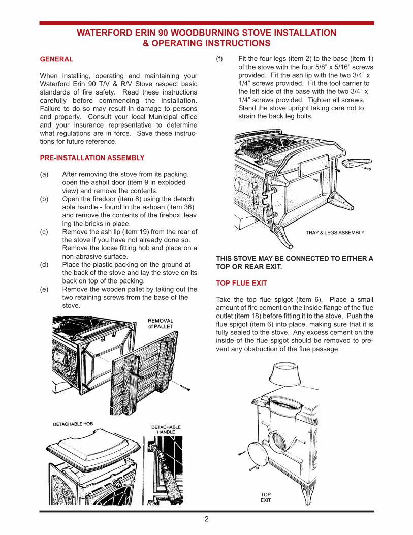
(f) Fit the four legs (item 2) to the base (item 1)
of the stove with the four 5/8” x 5/16” screws
provided. Fit the ash lip with the two 3/4” x
1/4” screws provided. Fit the tool carrier to
the left side of the base with the two 3/4” x
1/4” screws provided. Tighten all screws.
Stand the stove upright taking care not to
strain the back leg bolts.
THIS STOVE MAY BE CONNECTED TO EITHER A
TOP OR REAR EXIT.
TOP FLUE EXIT
Take the top flue spigot (item 6). Place a small
amount of fire cement on the inside flange of the flue
outlet (item 18) before fitting it to the stove. Push the
flue spigot (item 6) into place, making sure that it is
fully sealed to the stove. Any excess cement on the
inside of the flue spigot should be removed to pre-
vent any obstruction of the flue passage.
2

REAR FLUE EXIT
Fit the top cover plate (item 5) to the stove with the
screws holding on the rear exit cover plate (item 68).
Make sure that all the sealing rope is properly
sealed to the stove flue outlet (item 18).
HEAT SHIELD
Fit the rear heat shield as follows: Screw the four 4”
x 1/4” bolts (item 69) to the back plate (item 23). Fit
the four 2” spacers (item 70) over the tie bolts. Fit
the inner heat shield (item 75) without the blanking
plate (item 72) onto the four tie bolts. Now fit the 1”
spacers (item 71) over the tie bolts and fit the outer
heat shield panel (item 76) without the blanking plate
(item 72). Tighten the whole assembly together
using the four 1/4” nuts provided.
FLOOR PROTECTION
When installing this heater on a combustible floor, a
floor protector, consisting of a layer of non-com-
bustible material at least 3/8” thick or 1/4” thick cov-
ered with 1/8” sheet metal is required to cover the
area under the heater and to extend to at least 18”
at the front and 8” to the sides, and embers which
may fall out from the door when stoking or fuelling.
LOCATION
There are several conditions to be considered when
selecting a location for your Waterford Erin 90 T/V &
R/V Stove.
(a) Distance from a safe chimney.
(b) Position in the area to be heated - central
locations are usually best.
(c) Allowance for proper clearances to com
bustibles.
(d) Obstruction in the ceiling, upper floor or roof,
for example, ducting plumbing, electrical fit
tings and wiring, overhead fixed furnishings
etc.
WARNING
DO NOT OBSTRUCT FREE AIR SUPPLY TO THE
SECONDARY AIR DUCT AT THE REAR OF THE
STOVE.
3
With rear heatshield fitted
for rear outlet configura-
tion.
Rear heat
shield fitted
complete with
shielded chim-
ney connector
for a rear outlet
configuration.
Chimney con-
nector and pipe
shield not sup-
plied as stan-
dard.
1 inch space
REAR
EXIT
FITTING OF REAR HEAT
SHIELD

MINIMUM CLEARANCES TO COMBUSTIBLES
From the front of the stove 48” - 1200mm
From back of stove 24” - 600mm
From the side of stove 19” - 480mm
From corner installation 12” - 300mm
From the flue pipe 23” - 580mm
Mantle clearance 26 1/2” - 675mm
Side trim, which extends
less than 2” from the face
of the fireplace 10” - 250mm
MANTLE & TRIM CLEARANCES
If the stove is to be installed using the rear exit
option then the UL/ULC listed Optional rear heat
shield must be fitted together with a listed pipe
shield fitted from the heat shield to the back wall on
the underside of the chimney connector.
(See horizontal installation).
Rear Exit
From back of stove 12” - 300mm
From side of stove 19” - 480mm
plate (item 72) and the double top flue spigot shield
(item 74) over the tie bolts and tighten the whole
assembly together using the four 1/4” nuts provided.
When the Waterford listed heat shields are used
together with a listed pipe shield using the top exit
option the clearances may be reduced to 91/2”.
(Pipe shield and heat shields are not supplied as
standard.
4
REDUCED CLEARANCES
Under certain conditions the minimum clearances
may be reduced by means of:
(a) Listed Waterford rear heat shield assembly
installed in accordance with the manufactur
ers instructions.
(b) Shields constructed in accordance with
NFPA211 (USA) Can3-B365 installation
code for solid fuel fired appliances.
(c) Fitting the listed Waterford Heat Shield and
chimney connector pipe shield.
REAR HEAT SHIELD
If the stove e is to be connected to a top flue exit
then the rear heat shield assembly must be fitted as
follows: Screw the four 4” x 1/4” heat shield tie bolts
(item 69) to the back plate (item 23). Fit the four 2”
spacers (item 70) over the heat shield tie bolts. Fit
the inner heat shield (item 75) complete with rear
heat shield blanking plate (item 72) onto the four
heat shield tie bolts. Now fit the four 1” spacers
(item 71) over the tie bolts and fit the outer heat
shield (item 76) complete with heat shield blanking
1 inch spacer
Fitting of listed pipe
shield.
Pipe shield and chimney
connector are not sup-
plied as standard with
the stove.
Fitting of rear heat
shield
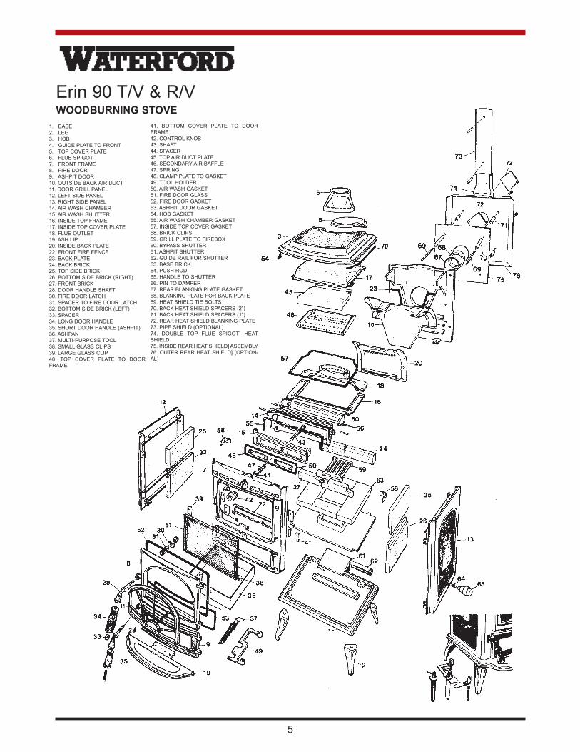
Erin 90 T/V & R/VWOODBURNING STOVE
1. BASE
2. LEG
3. HOB
4. GUIDE PLATE TO FRONT
5. TOP COVER PLATE
6. FLUE SPIGOT
7. FRONT FRAME
8. FIRE DOOR
9. ASHPIT DOOR
10. OUTSIDE BACK AIR DUCT
11. DOOR GRILL PANEL
12. LEFT SIDE PANEL
13. RIGHT SIDE PANEL
14. AIR WASH CHAMBER
15. AIR WASH SHUTTER
16. INSIDE TOP FRAME
17. INSIDE TOP COVER PLATE
18. FLUE OUTLET
19. ASH LIP
20. INSIDE BACK PLATE
22. FRONT FIRE FENCE
23. BACK PLATE
24. BACK BRICK
25. TOP SIDE BRICK
26. BOTTOM SIDE BRICK (RIGHT)
27. FRONT BRICK
28. DOOR HANDLE SHAFT
30. FIRE DOOR LATCH
31. SPACER TO FIRE DOOR LATCH
32. BOTTOM SIDE BRICK (LEFT)
33. SPACER
34. LONG DOOR HANDLE
35. SHORT DOOR HANDLE (ASHPIT)
36. ASHPAN
37. MULTI-PURPOSE TOOL
38. SMALL GLASS CLIPS
39. LARGE GLASS CLIP
40. TOP COVER PLATE TO DOOR
FRAME
41. BOTTOM COVER PLATE TO DOOR
FRAME
42. CONTROL KNOB
43. SHAFT
44. SPACER
45. TOP AIR DUCT PLATE
46. SECONDARY AIR BAFFLE
47. SPRING
48. CLAMP PLATE TO GASKET
49. TOOL HOLDER
50. AIR WASH GASKET
51. FIRE DOOR GLASS
52. FIRE DOOR GASKET
53. ASHPIT DOOR GASKET
54. HOB GASKET
55. AIR WASH CHAMBER GASKET
57. INSIDE TOP COVER GASKET
58. BRICK CLIPS
59. GRILL PLATE TO FIREBOX
60. BYPASS SHUTTER
61. ASHPIT SHUTTER
62. GUIDE RAIL FOR SHUTTER
63. BASE BRICK
64. PUSH ROD
65. HANDLE TO SHUTTER
66. PIN TO DAMPER
67. REAR BLANKING PLATE GASKET
68. BLANKING PLATE FOR BACK PLATE
69. HEAT SHIELD TIE BOLTS
70. BACK HEAT SHIELD SPACERS (2”)
71. BACK HEAT SHIELD SPACERS (1”)
72. REAR HEAT SHIELD BLANKING PLATE
73. PIPE SHIELD (OPTIONAL)
74. DOUBLE TOP FLUE SPIGOT] HEAT
SHIELD
75. INSIDE REAR HEAT SHIELD] ASSEMBLY
76. OUTER REAR HEAT SHIELD] (OPTION-
AL)
5
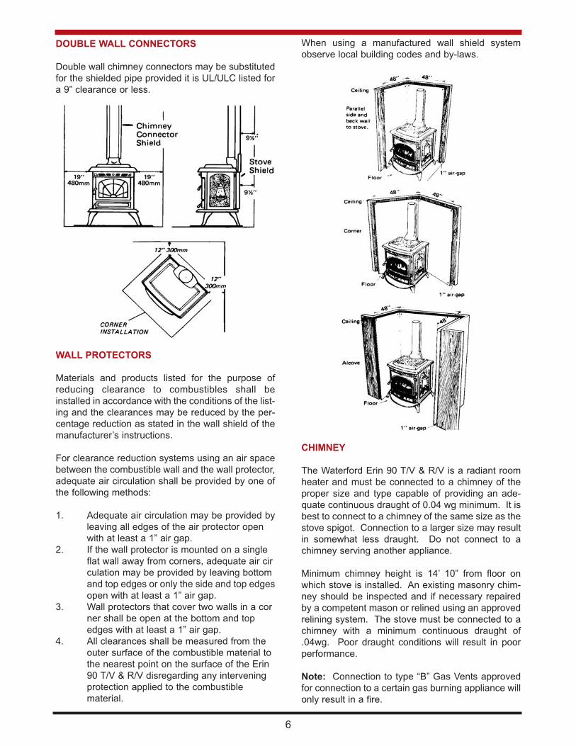
DOUBLE WALL CONNECTORS
Double wall chimney connectors may be substituted
for the shielded pipe provided it is UL/ULC listed for
a 9” clearance or less.
WALL PROTECTORS
Materials and products listed for the purpose of
reducing clearance to combustibles shall be
installed in accordance with the conditions of the list-
ing and the clearances may be reduced by the per-
centage reduction as stated in the wall shield of the
manufacturer’s instructions.
For clearance reduction systems using an air space
between the combustible wall and the wall protector,
adequate air circulation shall be provided by one of
the following methods:
1. Adequate air circulation may be provided by
leaving all edges of the air protector open
with at least a 1” air gap.
2. If the wall protector is mounted on a single
flat wall away from corners, adequate air cir
culation may be provided by leaving bottom
and top edges or only the side and top edges
open with at least a 1” air gap.
3. Wall protectors that cover two walls in a cor
ner shall be open at the bottom and top
edges with at least a 1” air gap.
4. All clearances shall be measured from the
outer surface of the combustible material to
the nearest point on the surface of the Erin
90 T/V & R/V disregarding any intervening
protection applied to the combustible
material.
When using a manufactured wall shield system
observe local building codes and by-laws.
CHIMNEY
The Waterford Erin 90 T/V & R/V is a radiant room
heater and must be connected to a chimney of the
proper size and type capable of providing an ade-
quate continuous draught of 0.04 wg minimum. It is
best to connect to a chimney of the same size as the
stove spigot. Connection to a larger size may result
in somewhat less draught. Do not connect to a
chimney serving another appliance.
Minimum chimney height is 14’ 10” from floor on
which stove is installed. An existing masonry chim-
ney should be inspected and if necessary repaired
by a competent mason or relined using an approved
relining system. The stove must be connected to a
chimney with a minimum continuous draught of
.04wg. Poor draught conditions will result in poor
performance.
Note: Connection to type “B” Gas Vents approved
for connection to a certain gas burning appliance will
only result in a fire.
6

CHIMNEY TYPES: USA ONLY
The stove must be connected to a UL listed residen-
tial type HT and Building Heating Appliance chimney
installed in accordance with the manufacturers
instructions or a masonry chimney constructed in
accordance with NFPA211 Chimney Vents and Solid
Fuel Burning Appliances.
CHIMNEY TYPES: CANADA ONLY
The stove must be connected to an Underwriters
Laboratories of Canada labelled factory built 650oC
chimney, installed in accordance with the manufac-
turers instructions or in a lined masonry chimney
acceptable to the Authority having jurisdiction.
CHIMNEY CONNECTOR
The chimney connector is a smoke pipe used to
connect the Waterford Erin 90 T/V & R/V Stove to
the chimney described above. The chimney con-
nector must be made of Corrosion Resistant Steel,
24 gauge or heavier (Black or Blued or equivalently
treated steel). Be sure to fasten the chimney con-
nectors together and also to the flue outlet of the
stove through the two holes provided, use at least
two screws for each joint. Be sure that the joints are
tight and fully secured.
CHIMNEY CONNECTOR USA ONLY
Connectors should maintain a pitch or rise of at least
1/4” to the foot from the stove to the chimney. It
should be installed so as to avoid sharp turns or
other construction features that would create exces-
sive resistance to the flow of flue gases. It should be
securely supported with joints fastened with sheet-
metal screws, rivets, or other approved means. The
entire length of a connector should be readily acces-
sible for inspection, cleaning, and replacement.
The connector may pass through walls or partitions
constructed of combustible materials provided the
connector is either listed for wall pass-through or is
routed through a device listed for wall pass-through
and is installed in accordance with the conditions of
the listing. Any unexposed metal that is used as part
of a wall pass-through system and is exposed to flue
gases shall be constructed of stainless steel or other
equivalent material that will resist corrosion, soften-
ing, or cracking from flue gas at temperatures up to
982oC.
CONNECTING TO MASONRY CHIMNEY
The connector to a masonry chimney must extend
through the wall to the inner face or liner but not
beyond, and must be firmly cemented to masonry.
The connector may pass through walls or partitions
construction of combustible material to a masonry
chimney provided the connector system selected is
installed in accordance with the proper clearances
and conditions. (See figs. A,B,C,D page 8)
THIMBLES
Thimbles for chimneys or vent connector should be
of fire clay (ASTM c 315, Specifications for Clay Flue
Linings) galvanised steel of minimum thickness of
24 gauge, or material of equivalent durability.
Thimbles should be installed without damage to the
liner. The thimble should extend through the wall to,
but not beyond, the inner face of the liner and should
be firmly cemented to masonry.
Thimbles should be located to provide adequate
pitch or rise of chimney or vent connectors and,
where the ceiling above the appliance is constructed
of combustible material, the location of the thimble
should provide minimum clearance required for the
connector as specified in Section under minimum
clearances to combustibles.
Insulation material used as part of wall pass-through
system should be of non-combustible material and
should have a thermal conductivity of 1.0 Btu.in./ft.F
(4.88kg.cal/hr.m.C) or less. All clearances and thick-
nesses are minimums; larger clearances and thick-
nesses are acceptable. Any material used to close
up an opening for the connector should be of non-
combustible material. A connector to a masonry
chimney, except for system 2 (Under heading
Chimney Connector Systems, Thimbles and
Clearances), shall extend to piece through the wall
pass-through system and the chimney wall to the
inner face of the flue liner, but not beyond.
CHIMNEY CONNECTOR SYSTEMS, THIMBLES,
AND CLEARANCES FROM COMBUSTIBLE
WALLS
1. Minimum 31/2” thick brick masonry wall
framed into combustible wall with a min. of
12” brick separation from clay liner to com
bustibles. Fire clay liner (ASTM C315 or
equivalent) min. 5/8” wall thickness, should
run from outer surface of brick wall to, but not
beyond, the inner surface of chimney flue
liner and should be firmly cemented in place.
2. Solid insulated listed factory-built chimney
length of the same inside diameter as the
chimney connector and having 1” or more of
insulation with a min. 9” air space between
the outer wall of the chimney length and
combustibles. The inner and end of the
chimney length shall be flush with the inside
of the masonry chimney flue and shall be
sealed to the flue and to the brick masonry
7

penetration with nonwater-soluble refractory
cement. Supports should be securely fas
tened to wall surfaces on all sides. Fasteners
between supports and the chimney length
shall not penetrate the chimney liner.
3. Sheet metal chimney connector, min. 24
gauge in thickness, with a ventilated thimble,
min. 24 gauge in thickness, having two 1” air
channels, separated from combustibles by a
min. of 6” of glass fibre insulation. Opening
should be covered and thimble supported
with a sheet steel support, min. 24 gauge in
thickness. Support should be securely fas
tened to wall surfaces on all sides and
should be sized to fit and hold chimney
section. Fasteners used to secure chimney
sections should not penetrate chimney flue
liner.
4. Solid insulated listed factory-built chimney
length with an inside diameter 2” larger than
the chimney connector and having 1” or
more of insulation, serving as a pass-
through for a single wall sheet steel chimney
connector of min. 24 gauge thickness, with a
min. 2” air space between the outer wall of
chimney section and combustibles. Min.
length of chimney section shall be 12”.
Chimney section concentric with and spaced
1” away from connector by means of sheet
steel support plates on both ends of chimney
section. Opening shall be covered and
chimney section supported on both sides
with sheet steel supports of min. 24 gauge
thickness.
Supports should be securely fastened to wall sur-
face on all sides and shall be sized to fit and hold
chimney section. Fasteners used to secure chimney
sections should not penetrate chimney flue liner.
8
FIGURE B
FIGURE A
FIGURE C

MASONRY FIRE PLACE
The stove may be installed on the hearth extension
of a masonry fireplace. In Canada a continuous
liner must be provided from the flue collar of the
stove on the top of the chimney. In the USA a con-
tinuous chimney flue is required. A minimum clear-
ance of 26 1/2” (675mm) is required to combustible
mantle and a minimum clearance of 10” (250mm) to
side trim, which extends less than 2” (50mm) from
the face of the fireplace. (See section under
Minimum Clearances to Combustibles).
Before the Installation, the entire fireplace system
should be inspected for condition and code compli-
ance prior to connecting to the fireplace chimney.
Older fireplaces and chimneys may not have been
constructed to current-day codes.
The fireplace and chimney should be in, or brought
up to, acceptable conditions and proper clearances
should be met before connecting to the fireplace
chimney.
The size of the flue must be considered. If the fire-
place chimney is too large, a relining system may be
installed using an approved relining system.
Connection to a masonry chimney may be done by
breaching into the chimney from the front of the fire-
place, no less than 8” above the bottom of the first
flue tile, by installing a stainless steel or other listed
chimney connector from the appliance’s flue outlet
up through the fireplace damper and smoke cham-
ber, terminating at the first flue tile, or by installing a
stainless steel or other listed relining system from
the flue outlet up the entire length of the chimney,
where necessary.
Burn directly on hearth do not use a grate or elevate
fire. “Never use gasoline” gasoline type lantern fuel,
kerosene, charcoal lighter fluid or smaller liquids to
start or “freshen up” a fire in this heater. Keep all
such liquids well away from the heater while it is in
use. Operate stove only with fuelling door and ash
pit door closed. This heater is hot whilst in opera-
tion. Keep children, clothing and furniture a safe dis-
tance away.
LIGHTING
(a) Replace ashpan (item 36), close ashpit door
(item 9), and make sure the ash box shutter
(item 61) is closed by pushing in rod (item
64).
(b) Open firedoor (item 8) and open the primary
air inlet by turning the control knob (item 42)
on the front of the stove, one revolution anti-
clockwise, using the multi-purpose tool (item
37) provided.
(c) Cover hearth with crumpled pieces of paper.
Lay dry pieces of kindling approximately 1/2”
x 1/2” x 16” long on top of the paper towards
the back of the firebox. Ignite and close the
fire door (item 8). When the kindling has
ignited open the firedoor (item 8) and add
larger pieces of dry wood. Close the firedoor
(item 8). When a hot bed of coals is estab
lished add the normal fuel of well seasoned
split logs approximately 16” long. Once the
logs are well lighted, adjust the primary air
control knob (item 42) by turning it clockwise
to give the required heat output.
Refuelling - Open the firedoor (item 8) and carefully
level the embers and re-load with logs, close the
firedoor.
PRIMARY AIR SETTINGS
Maximum Fire. Fully Open
Between 15-20 minutes past the hour.
Medium High Burn.
Between 25-30 minutes past the hour.
Medium Low Burn.
Low Burn. Fully closed.
BURN WOOD ONLY, DO NOT BURN COAL,
SYNTHETIC LOGS OR OTHER FUELS.
9

IMPORTANT
Never allow a build-up of deposits in front of pilot
hole in the fire chamber. Always keep clear of ash,
coals, and fuel, check when lighting, re-fuelling or
de-ashing. See pilot illustration.
DISPOSAL OF ASHES
Remove ash carefully. Ashes should be placed in a
metal container with a tight fitting lid. The closed
container of ashes should be placed on a non-com-
bustible floor, or on the ground, well away from all
combustible materials, pending final disposal. If the
ashes are disposed of by burial in soil or otherwise
locally dispersed they should be retained in the
closed container until all cinders have thoroughly
cooled.
Replace the empty ashpan (item 36) in the stove,
close the ashpit door (item 9) and relight the fire.
LOW OR OVERNIGHT BURN
NOTE: The duration of low or overnight burn is
affected by:
Draught conditions: Excessive draught reduces
burn time. Quality of fuel load. If the stove and flue
temperature at the start of a low or overnight burn
are too high it will result in reducing burn time.
1. Allow the fire bed to cool down.
2. Re-load using full length wood (preferably
unsplit).
3. Do not pack the fuel load as high as the sec
ondary air baffle (item 46) at the top of the
firebox.
4. An air space is necessary between the fuel
load and the secondary air baffle (item 46) to
avoid impingement of the secondary air on
the top of the fuel load resulting in speeding
up the burn rate.
5. Turn down the primary air control (item 42) to
the closed position, by turning it one revolu
tion clockwise.
DE-ASHING
When the ash build-up becomes excessive in the
fire chamber (3 1/2” (88mm) deep or so) it must be
removed by allowing the fire to burn out. When the
fire has burned out, open the firedoor (item 8). Pull
open the ashpit shutter (item 61). The control knob
(item 42) for this is on the right hand side of the
stove. Rake the ash into the ashpan (item 36)
through the grating in the centre of the hearth. Push
closed the ashpit shutter (item 61) and dispose of
the ashes by removing the ashpan (item 36) from
the stove.
10

MAINTENANCE
CREOSOTE - Formation and the need for removal.
When wood is burned slowly, it produces tar and
other organic vapours, which combine with expelled
moisture to form creosote. The creosote vapours
condense in the relatively cool chimney flue of a
slow burning fire. As a result creosote residue accu-
mulates on the flue lining. When ignited this cre-
osote makes an extremely hot fire. The chimney
connector and chimney should be inspected at least
twice monthly during the heating season to deter-
mine if a creosote build-up has occurred. If creosote
has accumulated it should be removed to reduce the
risk of chimney fire.
Inspect the chimney connector frequently. Tap the
connector with your finger when the pipe is cool. If
you hear a dull echo, the pipe may need cleaning.
Disassemble the chimney connector and clean the
sections. Replace corroded pipe sections. The fit-
ting of a slip-joint in the stove makes the dismantling
easy for cleaning and inspection of chimney and
stove.
When inspecting a masonry chimney, start at the
cleanout door, normally found in the basement, at
the base of the chimney, or on the outside. If your
chimney does not have a clean-out door it must be
inspected and cleaned by removing stove from
chimney.
GLASS REPLACEMENT
(a) Open the firedoor (item 8) fully.
(b) Remove the four corner screws and clips
(items 38 & 39) and carefully remove the
broken glass.
(c) Clean the glass recess in the door.
(d) Attach adhesive thermal tape to the
perimeter of the replacement glass.
11
(e) Place the thermal taped side of the glass into
the firedoor recess and replace the four
corner clips (items 38 & 39) and screws.
(f) Make sure that the large corner clip (item 39)
is fitted in the top right hand corner.
(g) Tighten screws.
(h) Replace glass only with ceramic glass 3/16”
(5mm) thick.
GLASS CLEANING
The glass will clean itself when there is sufficient
heat generated by the burning fuel. If a build-up of
creosote occurs on the glass due to poor draught
conditions, poor quality fuel or very low burning for
long periods of time, it is best to clean the glass
manually when glass is thoroughly cooled.
VITREOUS ENAMEL CLEANING
General cleaning must be carried out when the
stove is cool.
If this stove is finished in a high gloss vitreous
enamel, to keep the enamel in the best condition
observe the following tips:
1. Wipe over daily with a soapy damp cloth,
followed by a polish with a clean dry duster.
2. For stubborn deposits a soap impregnated
pad can be carefully used on the vitreous
enamel.
3. Use only products recommended by the
Vitreous Enamel Department Council, these
products carry the Vitramel label.
4. DO NOT USE ABRASIVE PADS OR OVEN
CLEANSERS CONTAINING CITRIC ACID
ON ENAMELLED SURFACES. ENSURE
THAT THE CLEANSER MANUFACTUR
ERS INSTRUCTIONS ARE ADHERED TO.

Waterford Stanley Ltd.,
Bilberry, Waterford, Ireland.
Tel: 051-302300
Fax: 051-302375
12 Rev: 001 DP 980128
FIRE SAFETY
To provide reasonable fire safety the following
should be given serious consideration.
(1) Do not overfire the stove, if the stove or
chimney connector glows, you are overfiring.
(2) Overfiring will also damage painted or
enamel finishes on the stove.
(3) The installation of fire detectors.
(4) A conveniently located class “A” fire extin
guisher to contend with small fires resulting
from burning embers.
(5) A practical evacuation plan.
(6) A plan to deal with a chimney fire as follows:
In the event of a chimney fire:
(a) Notify the fire department
(b) Prepare occupants for immediate
evacuation.
(c) Close all openings into the stove.
(d) While awaiting the fire department watch for
ignition to adjacent combustibles from over
heated stove pipe or from hot embers or
sparks from the chimney.
UNDER NO CIRCUMSTANCES SHOULD ANY
FLAMMABLE LIQUID, KEROSENE, LIGHTER
FLUID OR CHARCOAL-STARTERS BE USED TO
LIGHT THE FIRE. NEVER USE MANUFACTURED
LOGS.
“KEEP ALL SUCH LIQUIDS WELL AWAY FROM
STOVE WHILE IN USE”