Ericsson Review Vol 69 1992 3
36
ERICSSON REVIEW 3 An Introduction to the Ericsson Transport Network Architecture Control and Operation of SDH Network Elements AXD 4/1, a Digital Cross-Connect System 1992
-
Upload
felippe-canato -
Category
Documents
-
view
39 -
download
0
Transcript of Ericsson Review Vol 69 1992 3
ERICSSON REVIEW
3 An Introduction to the Ericsson Transport Network Architecture Control and Operation of SDH Network Elements AXD 4/1, a Digital Cross-Connect System
1992

I
ERICSSON REVIEW Number 3 • 1992 • Volume 69
Responsible publisher Bo Hedfors
Editor Per-Olof Thyselius
Editorial staff Martti Viitaniemi
Subscription Eva Karlstein
Subscription one year $30
Address S-126 25 Stockholm, Sweden
Published in English with four issues per year
Copyright Telefonaktiebolaget L M Ericsson
Contents 58 • An Introduction to the Ericsson Transport Network Architecture
62 • Control and Operation of SDH Network Elements
78 • AXD 4/1, a Digital Cross-Connect System
Cover Ericsson Transport Network Architecture offers a complete network solution for a managable Transport Network based on the Synchronous Digital Hierarchy
An Introduction to the Ericsson Transport Network Architecture
Stefan Danielsson
The telecommunications industry has formulated a number of new standards for a new transmission hierarchy, the Synchronous Digital Hierarchy, for the purpose of reducing operating costs and improving the service offered to users. Today's fixed transmission network will evolve into a managed and software-controlled Transport Network. The Transport Network will form the infrastructure of the future telecom network and so make for successful introduction of new services, such as broadband data.
The author describes the Ericsson Transport Network Architecture (ETNA), a complete system solution for a manageable synchronous Transport Network.
digital communication systems telecommunication networks telecommunication network management
Today's digital transmission systems are based on the Plesiochronous Digital Hierarchy (PDH) standard, which was introduced step-by-step to cater for demands for higher transmission capacity in the voice traffic network.
This has resulted in a network that allows interconnection between different vendors' transmission equipment at certain standardised electrical interfaces, but also a network in which configuration changes are effected through hard-wiring and for which standards for interconnection at the optical level have been lacking.
The complex network is difficult to manage and costly and time-consuming to adapt to
changing requirements for transmission capacity. It consists of a large number of multiplexers at different levels and volumes of cabling between them. The line systems are underutilised; often, less than 50 % of the capacity is used.
Until now, this approach has been acceptable, because the dominating voice-only traffic is predictable to some degree. But today, public network operators around the world are faced with increasing financial pressure, growing competition due to deregulated markets, and unprecedented demands from users who now view communications as a strategic business tool.
Business users, notably those requiring both data and voice communications, are seeking new levels of guaranteed quality and services. The time it takes to arrange leased-line services - several weeks, sometimes months - will no longer be tolerated. The network must provide bandwidth on demand.
Synchronous Digital Hierarchy Recognising these problems and demands, the telecommunications industry has formulated a number of new standards for a new transmission hierarchy, the Syn-
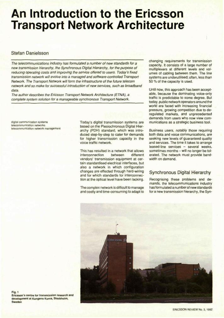
Fig. 1 Ericsson's centre for transmission research and development at Kungens Kurva, Stockholm, Sweden
ERICSSON REVIEW No. 3, 1992
59
STEFAN DANIELSSON Ericsson Telecom AB chronous Digital Hierarchy, aimed at eas
ing the difficulties for operators and improving the services offered to users. Included in SDH are standards for new transmission bit-rates, optical interfaces, information models and communication protocols for network management and proposals for network structures.
Future Transport Networks SDH offers many advantages and forms the foundation for the future transport network. SDH also underlies the Ericsson Transport Network Architecture (ETNA). ETNA is a single, open system concept that enables a public network operator to optimise his use of existing resources and make a smooth migration towards future broadband digital services.
Included in ETNA are all the transmission links, switching, routing and management facilities needed to deliver wideband and broadband services - data, voice, image and video. Network management is of the utmost importance. It is only through powerful network management that the cost and service benefits from SDH can be fully utilised.
ETNA consists of a family of Network Elements and one common Network Management system, FMAS (Facility Management System).
The Network Elements have basic functionality in common; they terminate electric and optical signals, perform switching at various signal levels and are controlled from FMAS. Due to somewhat different applications and optimisation criteria, two product lines are defined: Digital CrossConnect Systems (DXC) and SDH Transmission Systems (SMUX).
Digital Cross-Connect Systems DXCs are transmission channel switches for semi-permanent connections. With totally transparent switching characteristics, the DXC can terminate any PDH or SDH signal for selection and rerouting at any lower-order level. DXCs provide extensive switching capabilities for network restoration and network configuration in central hubs with heavy concentrations of circuits.
SDH Transmission Systems SDH transmission systems include a range of terminal multiplexers, intermediate regenerators and add/drop multiplexers based on SDH standards for transmission at 155 Mbit/s, 620 Mbit/s and 2.5 Gbit/s. The systems are built from a common set of modules to reduce the stockholding of spares and to simplify capacity upgrades. SMUXs are used in point-to-point, bus or ring configurations and provide a distributed type of network configuration with line or ring protection for network restoration.
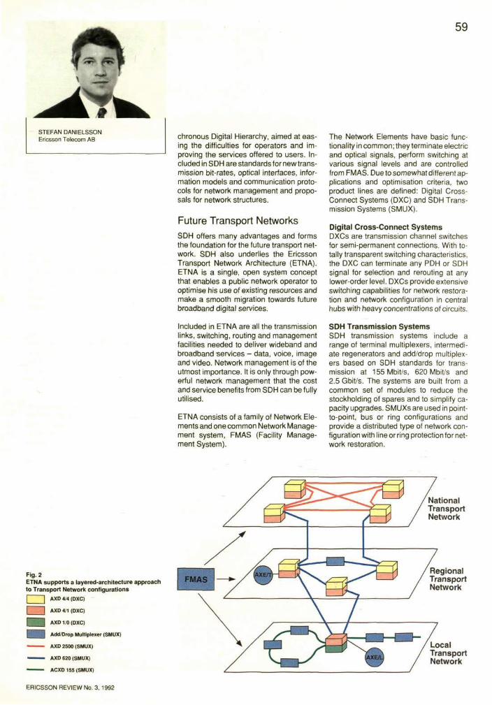
Fig. 2 ETNA supports a layered-architecture approach to Transport Network configurations
AXD 4/1 (DXC)
AXD 1/0 (DXC)
Add/Drop Multiplexer (SMUX)
AXD 2500 (SMUX)
AXD 620 (SMUX)
ACXD 155 (SMUX)
60
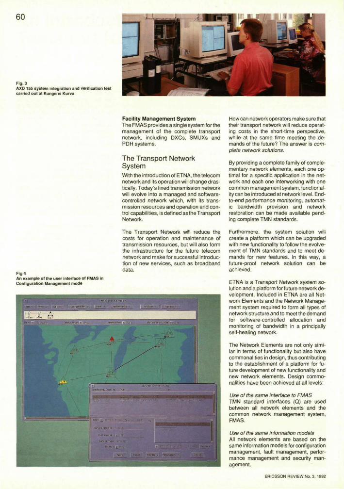
Fig. 3 AXD 155 system integration and verification test carried out at Kungens Kurva
Facility Management System The FMAS provides a single system for the management of the complete transport network, including DXCs, SMUXs and PDH systems.
The Transport Network System With the introduction of ETNA, the telecom network and its operation will change drastically. Today's fixed transmission network will evolve into a managed and software-controlled network which, with its transmission resources and operation and control capabilities, is defined as the Transport Network.
How can network operators make sure that their transport network will reduce operating costs in the short-time perspective, while at the same time meeting the demands of the future? The answer is complete network solutions.
By providing a complete family of complementary network elements, each one optimal for a specific application in the network and each one interworking with one common management system, functionality can be introduced at network level. End-to-end performance monitoring, automatic bandwidth provision and network restoration can be made available pending complete TMN standards.
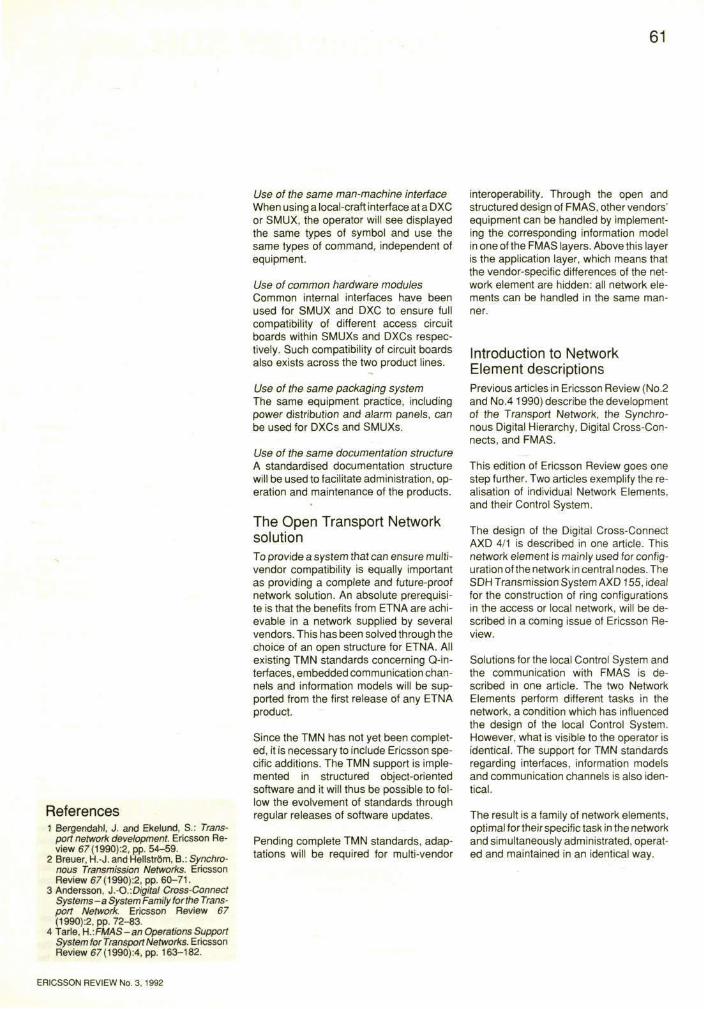
Fig 4 An example of the user interface of FMAS in Configuration Management mode
The Transport Network will reduce the costs for operation and maintenance of transmission resources, but will also form the infrastructure for the future telecom network and make for successful introduction of new services, such as broadband data.
Furthermore, the system solution will create a platform which can be upgraded with new functionality to follow the evolve-ment of TMN standards and to meet demands for new features. In this way, a future-proof network solution can be achieved.
ETNA is a Transport Network system solution and a platform for future network development. Included in ETNA are all Network Elements and the Network Management system required to form all types of network structure and to meet the demand for software-controlled allocation and monitoring of bandwidth in a principally self-healing network.
The Network Elements are not only similar in terms of functionality but also have commonalities in design, thus contributing to the establishment of a platform for future development of new functionality and new network elements. Design commonalities have been achieved at all levels:
Use of the same interface to FMAS TMN standard interfaces (Q) are used between all network elements and the common network management system, FMAS.
Use of the same information models All network elements are based on the same information models for configuration management, fault management, performance management and security management.
ERICSSON REVIEW No. 3, 1992
61
References 1 Bergendahl, J. and Ekelund, S.: Trans
port network development. Ericsson Review 67(1990):2, pp. 54-59.
2 Breuer, H.-J. and Hellstrom, B.: Synchronous Transmission Networks. Ericsson Review 67(1990):2, pp. 60-71.
3 Andersson, J.-O.-.Digital Cross-Connect Systems-a System Family for the Transport Network. Ericsson Review 67 (1990):2, pp. 72-83.
4 Tarle, H..FMAS - an Operations Support System for Transport Networks. Ericsson Review 67(1990):4, pp. 163-182.
Use of the same man-machine interface When using a local-craft interface at a DXC or SMUX, the operator will see displayed the same types of symbol and use the same types of command, independent of equipment.
Use of common hardware modules Common internal interfaces have been used for SMUX and DXC to ensure full compatibility of different access circuit boards within SMUXs and DXCs respectively. Such compatibility of circuit boards also exists across the two product lines.
Use of the same packaging system The same equipment practice, including power distribution and alarm panels, can be used for DXCs and SMUXs.
Use of the same documentation structure A standardised documentation structure will be used to facilitate administration, operation and maintenance of the products.
The Open Transport Network solution To provide a system that can ensure multi-vendor compatibility is equally important as providing a complete and future-proof network solution. An absolute prerequisite is that the benefits from ETNA are achievable in a network supplied by several vendors. This has been solved through the choice of an open structure for ETNA. All existing TMN standards concerning Q-in-terfaces, embedded communication channels and information models will be supported from the first release of any ETNA product.
Since the TMN has not yet been completed, it is necessary to include Ericsson specific additions. The TMN support is implemented in structured object-oriented software and it will thus be possible to follow the evolvement of standards through regular releases of software updates.
Pending complete TMN standards, adaptations will be required for multi-vendor
interoperability. Through the open and structured design of FMAS, other vendors' equipment can be handled by implementing the corresponding information model in one of the FMAS layers. Above this layer is the application layer, which means that the vendor-specific differences of the network element are hidden: all network elements can be handled in the same manner.
Introduction to Network Element descriptions Previous articles in Ericsson Review (No.2 and No.4 1990) describe the development of the Transport Network, the Synchronous Digital Hierarchy, Digital Cross-Connects, and FMAS.
This edition of Ericsson Review goes one step further. Two articles exemplify the realisation of individual Network Elements, and their Control System.
The design of the Digital Cross-Connect AXD 4/1 is described in one article. This network element is mainly used for configuration of the network in central nodes. The SDH Transmission System AXD 155, ideal for the construction of ring configurations in the access or local network, will be described in a coming issue of Ericsson Review.
Solutions for the local Control System and the communication with FMAS is described in one article. The two Network Elements perform different tasks in the network, a condition which has influenced the design of the local Control System. However, what is visible to the operator is identical. The support for TMN standards regarding interfaces, information models and communication channels is also identical.
The result is a family of network elements, optimal for their specific task in the network and simultaneously administrated, operated and maintained in an identical way.
ERICSSON REVIEW No. 3, 1992
Control and Operation of SDH Network Elements
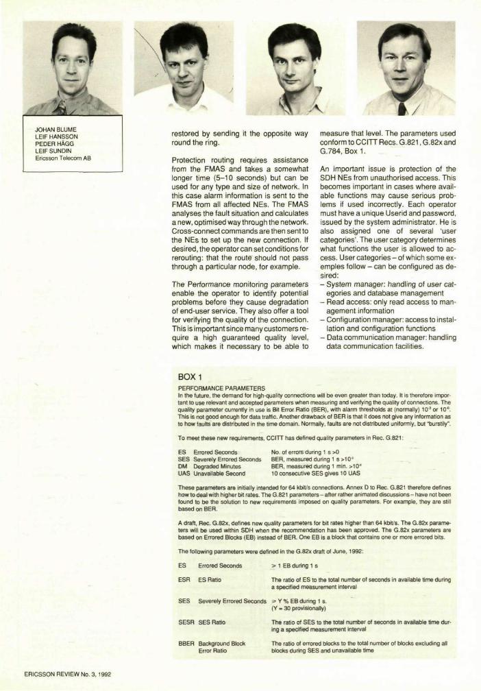
Johan Blume, Leif Hansson, Peder Hagg and Leif Sundin
Increasingly, flexible and powerful network management solutions allowing Network Elements and Operations Systems to work in a multi-vendor environment are becoming a key issue to network operators. The Synchronous Digital Hierarchy currently being standardised provides the required capabilities. The authors describe the main characteristics of SDH management and discuss some implementation aspects of control systems developed for Ericsson's SDH Network Elements.
digital communication systems telecommunication networks telecommunication network management
Abbreviations ACSE Association Control Service Element API Application Programmer's Interface AUI Attachment Unit Interface CLNP Conectionless Network Protocol CMISE Common Management Information Ser
vice Element CP Central Processor CPU Central Processor Unit CS Control System CSA Control System Application CSP Control System Platform DCC Data Communications Channel DCN Data Communications Network ECC Embedded Control Channel ETNA Ericsson Transport Network Architecture FMAS Facility Management System GNE Gateway Network Element GUI Graphical User Interface ICN Internal Communications Network IM Information Model IPC Inter-Process Communication ISDN Intergrated Sevices Digital Network LAPD Link Access Protocol on D-channel LAN Local Area Network
Background and Driving Forces Today's transmission network typically consists of inflexible equipment without provision for remote reconfiguration, and fixed hard-wired point-to-point connections. This means that each change of configuration - when supplying a 2 Mbit/s leased line, for example - requires hardwiring, which is time-consuming and therefore costly.
The Synchronous Digital Hierarchy (SDH) eliminates these disadvantages by providing flexible Network Elements (NE) capable of being configured remotely. This makes it possible to provide new broadband services - such as 2 Mbit/s leased lines - to customers in a short time and at low cost.
Another characteristic of today's transmission networks is that each vendor has his
LLC MAC MAU MCF MIB MO NE OS OSI PDH PI PM ROSE SDH SDXC SEMF
SMS SMUX SNI SNPA
su TAU TMN
UP
Logical Link Control Medium Access Control Medium Attachment Unit Message Communications Function Management Information Base Managed Object Network Element Operations System Open Systems Interconnection Plesiochronous Digital Hierarchy Physical Interface Performance Monitoring Remote Operations Service Element Synchronous Digital Hierarchy SDH Digital Cross Connect Synchronous Equipment Management Function SDH Management Subnetwork SDH Multiplexer Switching Network Interface Sub-Network Point of Attachment Support Unit Termination Access Unit Telecommunications Management Network Unit Processor
own management system with proprietary interfaces and functionality. This situation often necessitates adaptations when new equipment is introduced on a market, which is costly in terms of time, resources and money, both for the supplier and the operator.
One of the major driving forces behind SDH is improved and standardised management interfaces and functions, allowing the SDH Network Elements and Operations Systems (OS) to interwork in a multi-vendor environment.23
Benefits of SDH and ETNA Functional overview Introducing SDH in the transport network will improve operation and maintenance, and so reduce the operational cost for the Telecom operator. SDH also enables the operator to control the network more efficiently, in comparison with the conditions afforded by existing transmission systems.
SDH makes it possible to set up new connections from a remote site within a few seconds. This enables a Telecom operator to respond quickly to customer demands for new or higher capacity. It also reduces the operational cost because less manpower is required.
Self-healing networks can be configured in such a way that faults in the network - e.g. cable breaks - will not affect the traffic for more than a few milliseconds, or seconds, depending on the size of the network and the restoration principle applied. At present it can take hours, or even days, to locate the fault and take appropriate actions.
Two different principles are applied to protect the network against the effects of a fault: protection switching and protection routing.
Protection switching is performed by the SDH NE without assistance from a central network management system, such as Ericsson's FMAS. This means very fast restoration but utilises network resources quite inefficiently.
It is anticipated that rings will be a commonly used network topology in SDH networks, especially in local networks. In the event of a cable break, the traffic can be
ERICSSON REVIEW No. 3, 1992
restored by sending it the opposite way round the ring.
Protection routing requires assistance from the FMAS and takes a somewhat longer time (5-10 seconds) but can be used for any type and size of network. In this case alarm information is sent to the FMAS from all affected NEs. The FMAS analyses the fault situation and calculates a new, optimised way through the network. Cross-connect commands are then sent to the NEs to set up the new connection. If desired, the operator can set conditions for rerouting: that the route should not pass through a particular node, for example.
The Performance monitoring parameters enable the operator to identify potential problems before they cause degradation of end-user service. They also offer a tool for verifying the quality of the connection. This is important since many customers require a high guaranteed quality level, which makes it necessary to be able to
measure that level. The parameters used conform to CCITT Recs. G.821, G.82x and G.784, Box 1.
An important issue is protection of the SDH NEs from unauthorised access. This becomes important in cases where available functions may cause serious problems if used incorrectly. Each operator must have a unique Userid and password, issued by the system administrator. He is also assigned one of several 'user categories'. The user category determines what functions the user is allowed to access. User categories - of which some ex-emples follow - can be configured as desired: - System manager: handling of user cat
egories and database management - Read access: only read access to man
agement information - Configuration manager: access to instal
lation and configuration functions - Data communication manager: handling
data communication facilities.
BOX1 PERFORMANCE PARAMETERS In the future, the demand for high-quality connections will be even greater than today. It is therefore important to use relevant and accepted parameters when measuring and verifying the quality of connections. The quality parameter currently in use is Bit Error Ratio (BER), with alarm thresholds at (normally) 103 or 10*. This is not good enough for data traffic. Another drawback of BER is that it does not give any information as to how faults are distributed in the time domain. Normally, faults are not distributed uniformly, but "burstily".
To meet these new requirements, CCITT has defined quality parameters in Rec. G.821:
ES Errored Seconds SES Severely Errored Seconds DM Degraded Minutes UAS Unavailable Second
No. of errors during 1 s >0 BER, measured during 1 s >10' BER, measured during 1 min. MO* 10 consecutive SES gives 10 UAS
These parameters are initially intended for 64 kbit/s connections. Annex D to Rec. G.821 therefore defines how to deal with higher bit rates. The G.821 parameters - after rather animated discussions- have not been found to be the solution to new requirements imposed on quality parameters. For example, they are still based on BER.
A draft, Rec. G.82x, defines new quality parameters for bit rates higher than 64 kbit/s. The G.82x parameters will be used within SDH when the recommendation has been approved. The G.82x parameters are based on Errored Blocks (EB) instead of BER. One EB is a block that contains one or more errored bits.
The following parameters were defined in the G.82x draft of June, 1992:
ES Errored Seconds
ESR ES Ratio
SES Severely Errored Seconds
SESR SES Ratio
s= 1 EB during 1 s
The ratio of ES to the total number of seconds in available time during a specified measurement interval
ss Y % EB during 1 s. (Y > 30 provisionally)
The ratio of SES to the total number of seconds in available time during a specified measurement interval
BBER Background Block The ratio of errored blocks to the total number of blocks excluding all Error Ratio blocks during SES and unavailable time
JOHAN BLUME LEIF HANSSON PEDER HAGG LEIF SUNDIN Ericsson Telecom AB
64
These functions and a number of other functions are described in greater detail and from the point of view of the SDH NEs in the section 'SDH Management'.
ment of large transport networks. The LOT is required during installation, and can also be used to manage a single NE or a small transport network.
Mode of operation The SDH NE can be managed from: - FMAS, the management system for the
Transport Network - A Local Operator Terminal (LOT).
The FMAS is necessary for the manage-
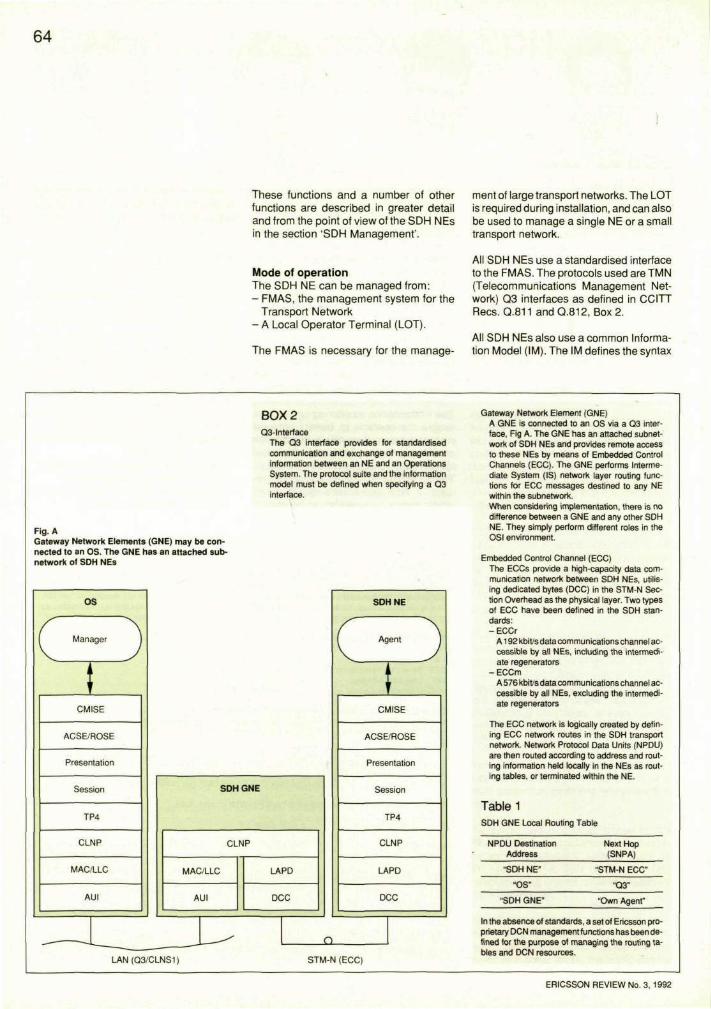
All SDH NEs use a standardised interface to the FMAS. The protocols used are TMN (Telecommunications Management Network) Q3 interfaces as defined in CCITT Recs. Q.811 and Q.812, Box 2.
All SDH NEs also use a common Information Model (IM). The IM defines the syntax
Fig. A Gateway Network Elements (GNE) may be connected to an OS. The GNE has an attached subnetwork of SDH NEs
BOX 2 Q3-lnterface
The Q3 interface provides for standardised communication and exchange of management information between an NE and an Operations System. The protocol suite and the information model must be defined when specifying a Q3 interface.
Gateway Network Element (GNE) A GNE is connected to an OS via a Q3 interface, Fig A. The GNE has an attached subnetwork of SDH NEs and provides remote access to these NEs by means of Embedded Control Channels (ECC). The GNE performs Intermediate System (IS) network layer routing functions for ECC messages destined to any NE within the subnetwork. When considering implementation, there is no difference between a GNE and any other SDH NE. They simply perform different roles in the OSI environment.
Embedded Control Channel (ECC) The ECCs provide a high-capacity data communication network between SDH NEs, utilising dedicated bytes (DCC) in the STM-N Section Overhead as the physical layer. Two types of ECC have been defined in the SDH standards: -ECCr
A192 kbit/sdata communications channel accessible by all NEs, including the intermediate regenerators
-ECCm A 576 kbit/s data communications channel accessible by all NEs, excluding the intermediate regenerators
The ECC network is logically created by defining ECC network routes in the SDH transport network. Network Protocol Data Units (NPDU) are then routed according to address and routing information held locally in the NEs as routing tables, or terminated within the NE.
Table 1 SDH GNE Local Routing Table
NPDU Destination Address
"SDH NE"
"OS"
"SDH GNE"
Next Hop (SNPA)
"STM-N ECC"
"Q3"
"Own Agent"
In the absence of standards, a set of Ericsson proprietary DCN management functions has been defined for the purpose of managing the routing tables and DCN resources.
ERICSSON REVIEW No. 3, 1992
65
of the messages that are sent between the SDH NEs and the FMAS.
SDH Management General SDH Management is based on TMN and OSI principles to allow for the building of an open network architecture. The basic concept behind TMN is to provide an organised architecture to achieve interconnection between various types of Operations System (OS) and/or telecommunications equipment for the exchange of management information, using standardised protocols and interfaces.
From a management point of view, the SDH NE can be considered from three different perspectives: - A functional perspective - An information model perspective - A data communication perspective, each of these perspectives defining some of the aspects necessary for standardised multi-vendor operations.
Functional Perspective The Functional perspective defines the management services that a single SDH NE can provide to a local operator, or to a network management system. In the TMN context, these functions are referred to as TMN management functions.
The TMN management functions belong to different management functional areas. Those relevant for SDH NEs are: Configuration Management, Fault Management, Performance Management and Security Management. In addition, a set of Data Communication Network management functions dealing with configuration of data communication resources have been defined.
Within ETNA, the SDH NE-related services are used by the FMAS to provide network-related services such as trail provisioning, protection routing, path performance monitoring, etc. Some examples of the most important TMN management functions provided are summarised below.
Configuration Management (CM) Compared with traditional transmission equipment, the SDH NEs also include a switch which provides for the set-up of broadband semi-permanent connections.
The main CM task is to control this switch, but CM also controls other aspects of the configuration of the NE: - Termination Point Provisioning
The different types of termination point, i.e. physical interfaces, trail termination points and connection termination points, can be configured in different ways, e.g. assigned identities, alarm thresholds, enabling and disabling of the laser, etc. The termination points are automatically created when the related printed board assemblies are inserted
- Equipment Configuration The SDH NEs are in many ways self-configurable after installation or extension of the hardware, e.g. when new access ports are installed. The equipment configuration functions keep track of the equipment currently installed, e.g. printed board assemblies and software, and report to the OS if changes have been made
- Cross-Connect The cross-connect functions set up connections through the switch and keep an up-to-date list of the cross-connections currently being ordered
- Protection Switching The SDH NEs can be configured to perform different types of autonomous protection switching (fast restoration) of paths or sections to dedicated standby network resources following a network failure
- Synchronisation Configuration Each NE must be synchronised from a valid synchronisation source, e.g. a 2 Mbit/s signal, a 2 MHz reference or an STM-N signal. The synchronisation source configuration functions define the synchronisation source to be used, and what actions should be taken when the primary source fails
- NE-Recovery The SDH NEs contain a lot of data which must be administered, e.g. regularly backed up. During certain trouble conditions it may also be necessary to perform restarts at different levels.
Fault Management (FM) Fault management provides functions for detection, isolation and correction of abnormal states in the network. This includes both network-related faults, resulting from cable breaks or deteriorating line systems, and abnormal conditions within the NEs themselves. The main FM task is to report
ERICSSON REVIEW No. 3, 1992
66
to the OS upon detection of a serious fault in the network, but it also controls diagnostic and test routines: - Alarm Surveillance
The SDH NEs have the capability to send alarm reports to the OS upon detection of a failure, and to store the alarms in an event log
- Fault Localisation and Testing The SDH NEs can be ordered to perform loopbacks, error injection, self-diagnostics, etc.
• User Categories A user category defines different levels of function access privileges that can be assigned to a user. The lowest privilege level is read access, and the highest level is the super-user category
• Users New users can be defined and assigned a user identity, password and user category. Users can also be deleted.
Performance Management (PM) Performance management deals with the functions necessary for an NE to collect, store, threshold, and report performance data associated with its monitored PDH and SDH trail terminations. All application-specific and optional parameters, as specified in CCITT Rec. G.784, are supported. - PM Data Attribute Setting
Basic PM data attributes, such as threshold values, can be defined
- PM Data Reporting The SDH NEs can send PM data reports to an OS, either when a defined threshold is exceeded (degraded or unacceptable performance level) or in accordance with predefined schedules
- PM Data Logging PM data can be stored in logs within the NEs and fetched by the OS when demanded.
Security Management (SM) Security management functions deal with user access control to protect the network against unauthorised access to resources and services. - Login/Logout
A local operator trying to access the NE is checked against a user identity and a password
DCN Management DCN Management provides the functions necessary to control and configure the data communication resources which allow communication to take place within the SDH Management Network.
- Network Node Configuration Each SDH NE can be configured as a data communication node in the OSI environment, which means that addresses, application entity titles and names used locally must be defined
- Network Route Configuration Network routes in the OSI context can be defined by means of routing tables and route priorities.
The Information Model Perspective Another, more formal way of describing the operation and control functionality is in terms of an Information Model (IM). An IM is an object-oriented description, independent of the actual physical realisation of the Network Element resources and how these are managed.
The Information Model consists of a collection of object classes, e.g. equipment, software, trail termination point, SDH
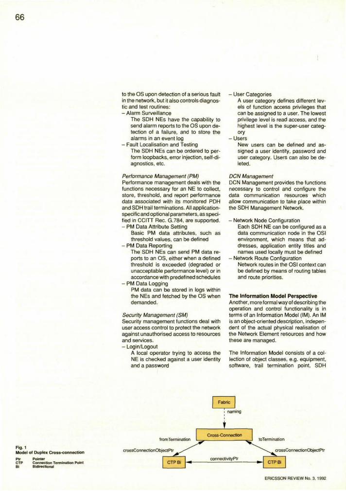
Fig.1 Model of Duplex Cross-connection
Ptr Pointer CTP Connection Termination Point Bi Bidirectional
ERICSSON REVIEW No. 3, 1992
67
switch fabric. The characteristics of an object class are specified in terms of - read/write attribute values in objects,
e.g. values of configuration parameters and relations to other objects, represented as lines between objects in Fig. 12 3
- create/delete operations of objects - actions that can be performed on the ob
ject - notifications (i.e. spontaneous messag
es) sent from the object.
In an executing system, manageable resources are represented as instances of these object classes. The collection of instantiated objects is referred to as the Management Information Base (MIB).2 There are two types of object in the MIB: Managed Objects and Support Objects. A Managed Object (MO) represents a physical or logical resource in the Network Element. A Support Object (SO) represents a log or an alarm filter, for example.
The link between the TMN management functions and the IM is the implementation of each management function as one or more operations, actions or notifications in the objects that build up the MIB.
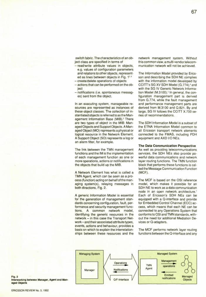
A Network Element has what is called a TMN Agent, which can be seen as a process (function) acting on behalf of the managing system(s), relaying messages in both directions, Fig. 2.
A generic Information Model is essential for the generation of management standards concerning configuration, fault, performance and security management functions. A common network model, identifying the generic resources in the network - in this case the Transport Network- and their associated attribute types, events, actions and behaviour, provides a basis on which to explain the interrelationships between these resources and the
network management system. Without this common view, a multi-vendortelecom-munication network will not be achieved.
The Information Model provided by Ericsson and describing the SDH NE complies with the information model developed by CCITT's SG XV SDH Model (G.774),6 and with the SG IV Generic Network Information Model (M.3100).5 In general, the configuration management part is derived from G.774, while the fault management and performance management parts are derived from M.3100 and Q.821. By and large, SG IV follows the CCITT X.700 series of recommendations.
The SDH Information Model is a subset of the ETNA Information Model common to all Ericsson transport network elements connected to the FMAS, including PDH equipment and AXD I/O NEs.
The Data Communication Perspective As well as providing telecommunications services, the SDH NEs also provide powerful data communications and network layer routing functions. The TMN function block that performs these functions is called the Message Communication Function (MCF).
The MCF is based on the OSI reference model, which makes it possible for an SDH NE to work as a data communication node in an open network architecture.7
Each of Ericsson's SDH NEs can be equipped with a Q-interface and provide for Embedded Control Channel (ECC) access, which means that each NE can be connected to any Operations System that conforms to OSI and TMN standards, without the need for additional Mediation Devices or Q-adapters.
The MCF performs network layer routing functions between the Q-interface and any
Fig. 2 Interworking between Manager, Agent and Managed Objects
ERICSSON REVIEW No. 3, 1992
68
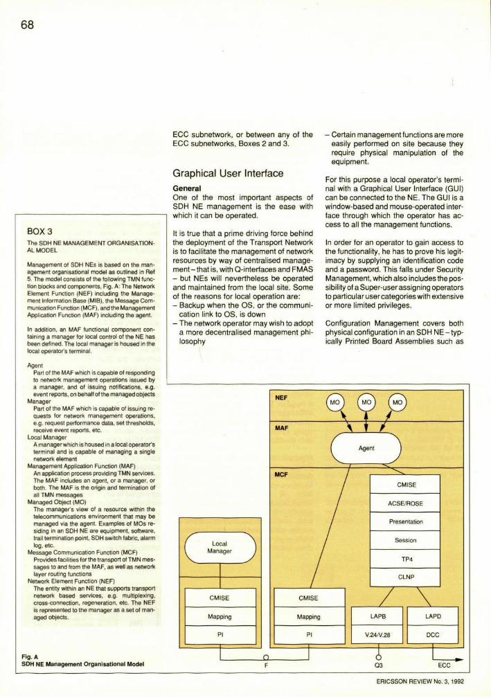
BOX 3 The SDH NE MANAGEMENT ORGANISATIONAL MODEL
Management of SDH NEs is based on the management organisational model as outlined in Ret 5. The model consists of the following TMN function blocks and components, Fig. A: The Network Element Function (NEF) including the Management Information Base (MIB), the Message Communication Function (MCF), and the Management Application Function (MAF) including the agent.
In addition, an MAF functional component containing a manager for local control of the NE has been defined. The local manager is housed in the local operator's terminal.
Agent Part of the MAF which is capable of responding to network management operations issued by a manager, and of issuing notifications, e.g. event reports, on behalf of the managed objects
Manager Part of the MAF which is capable of issuing requests for network management operations, e.g. request performance data, set thresholds, receive event reports, etc.
Local Manager A managerwhich is housed in a local operator's terminal and is capable of managing a single network element
Management Application Function (MAF) An application process providing TMN services. The MAF includes an agent, or a manager, or both. The MAF is the origin and termination of all TMN messages
Managed Object (MO) The manager's view of a resource within the telecommunications environment that may be managed via the agent. Examples of MOs residing in an SDH NE are equipment, software, trail termination point, SDH switch fabric, alarm log, etc.
Message Communication Function (MCF) Provides facilities for the transport of TMN messages to and from the MAF, as well as network layer routing functions
Network Element Function (NEF) The entity within an NE that supports transport network based services, e.g. multiplexing, cross-connection, regeneration, etc. The NEF is represented to the manager as a set of managed objects.
Fig. A SDH NE Management Organisational Model
ECC subnetwork, or between any of the ECC subnetworks, Boxes 2 and 3.
Graphical User Interface General One of the most important aspects of SDH NE management is the ease with which it can be operated.
It is true that a prime driving force behind the deployment of the Transport Network is to facilitate the management of network resources by way of centralised management - that is, with Q-interfaces and FMAS - but NEs will nevertheless be operated and maintained from the local site. Some of the reasons for local operation are: - Backup when the OS, or the communi
cation link to OS, is down - The network operator may wish to adopt
a more decentralised management philosophy
- Certain management functions are more easily performed on site because they require physical manipulation of the equipment.
For this purpose a local operator's terminal with a Graphical User Interface (GUI) can be connected to the NE. The GUI is a window-based and mouse-operated interface through which the operator has access to all the management functions.
In order for an operator to gain access to the functionality, he has to prove his legitimacy by supplying an identification code and a password. This falls under Security Management, which also includes the possibility of a Super-user assigning operators to particular user categories with extensive or more limited privileges.
Configuration Management covers both physical configuration in an SDH NE-typically Printed Board Assemblies such as
ERICSSON REVIEW No. 3, 1992
69
the Termination Access Unit - and a logical configuration of the capacities for switching and multiplexing. These different types of Configuration Management are supported by different graphical views, e.g. a physical view and a logical view.
When there is a fault of some kind, e.g. a Transport Network related alarm such as Loss of Frame Alignment or excessive Bit Error Ratio, or a fault related to HW or SW in the actual NE, the details and possible consequences are reported to the GUI. Fault Management, which deals with these functions, also covers testing and diagnostics.
Performance is continuously monitored, and the GUI presents the statistics graphically and/or in tabular form. These functions fall under Performance Management.
The local GUIs conform to design standards developed for user interfaces by TMOS User Interface Design Standards (TUIDS), which means that the OPEN LOOK™ user interface style is currently used for the SDXCs, but Motif will also be included. For the SMUXs, Microsoft Windows is used.
ETNA Harmonisation The current SDX Control System contains a GUI implemented on an IPX type Sun Workstation, but a portable terminal will also be provided. The GUI for SMUX is implemented on a PC 386/486. The fact that two different types of graphical terminal are used will not prevent 'look and feel' similarity between the systems, however.
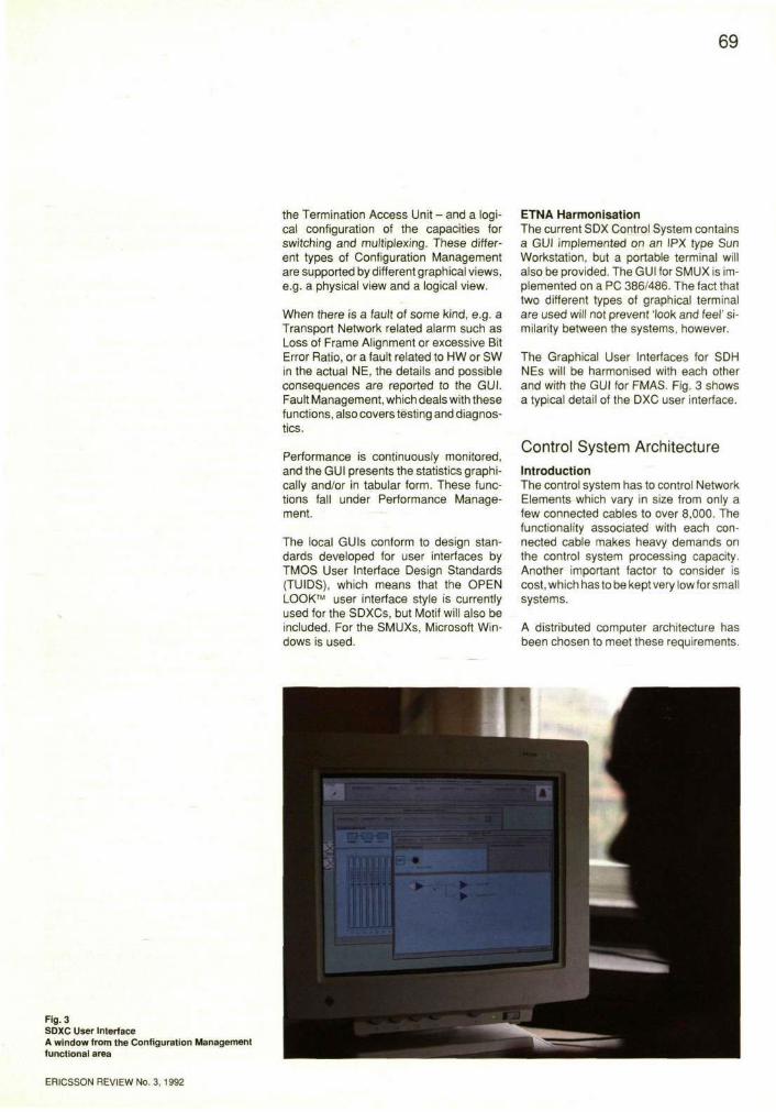
The Graphical User Interfaces for SDH NEs will be harmonised with each other and with the GUI for FMAS. Fig. 3 shows a typical detail of the DXC user interface.
Control System Architecture Introduction The control system has to control Network Elements which vary in size from only a few connected cables to over 8,000. The functionality associated with each connected cable makes heavy demands on the control system processing capacity. Another important factor to consider is cost, which has to be kept very low for small systems.
A distributed computer architecture has been chosen to meet these requirements.
Fig. 3 SDXC User Interface A window from the Configuration Management functional area
ERICSSON REVIEW No. 3, 1992
Each unit in the system has a powerful microprocessor, and a central master computer co-ordinates all the unit processors and provides input/output.
Unit processors enable the unit itself to perform a large amount of processing and so reduce the load on the central processor.
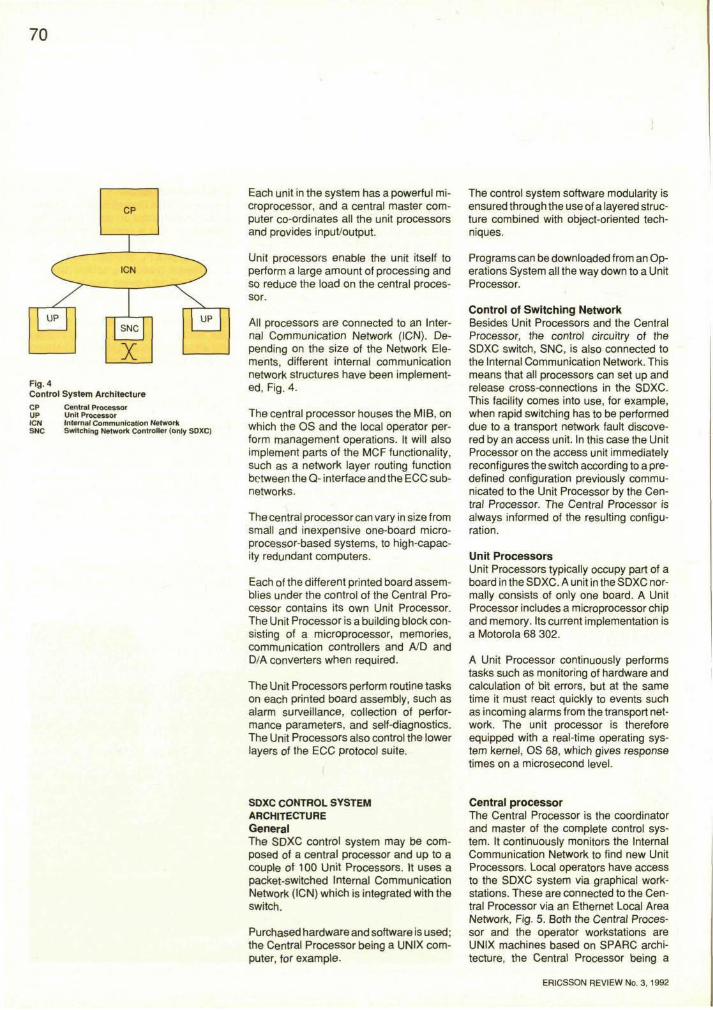
All processors are connected to an Internal Communication Network (ICN). Depending on the size of the Network Elements, different internal communication network structures have been implemented, Fig. 4.
The central processor houses the MIB, on which the OS and the local operator perform management operations. It will also implement parts of the MCF functionality, such as a network layer routing function between the Q- interface and the ECC subnetworks.
The central processor can vary in size from small and inexpensive one-board microprocessor-based systems, to high-capacity redundant computers.
Each of the different printed board assemblies under the control of the Central Processor contains its own Unit Processor. The Unit Processor is a building block consisting of a microprocessor, memories, communication controllers and A/D and D/A converters when required.
The Unit Processors perform routine tasks on each printed board assembly, such as alarm surveillance, collection of performance parameters, and self-diagnostics. The Unit Processors also control the lower layers of the ECC protocol suite.
SDXC CONTROL SYSTEM ARCHITECTURE General The SDXC control system may be composed of a central processor and up to a couple of 100 Unit Processors. It uses a packet-switched Internal Communication Network (ICN) which is integrated with the switch.
Purchased hardware and software is used; the Central Processor being a UNIX computer, for example.
The control system software modularity is ensured through the use of a layered structure combined with object-oriented techniques.
Programs can be downloaded from an Operations System all the way down to a Unit Processor.
Control of Switching Network Besides Unit Processors and the Central Processor, the control circuitry of the SDXC switch, SNC, is also connected to the Internal Communication Network. This means that all processors can set up and release cross-connections in the SDXC. This facility comes into use, for example, when rapid switching has to be performed due to a transport network fault discovered by an access unit. In this case the Unit Processor on the access unit immediately reconfigures the switch according to a predefined configuration previously communicated to the Unit Processor by the Central Processor. The Central Processor is always informed of the resulting configuration.
Unit Processors Unit Processors typically occupy part of a board in the SDXC. A unit in the SDXC normally consists of only one board. A Unit Processor includes a microprocessor chip and memory. Its current implementation is a Motorola 68 302.
A Unit Processor continuously performs tasks such as monitoring of hardware and calculation of bit errors, but at the same time it must react quickly to events such as incoming alarms from the transport network. The unit processor is therefore equipped with a real-time operating system kernel, OS 68, which gives response times on a microsecond level.
Central processor The Central Processor is the coordinator and master of the complete control system. It continuously monitors the Internal Communication Network to find new Unit Processors. Local operators have access to the SDXC system via graphical workstations. These are connected to the Central Processor via an Ethernet Local Area Network, Fig. 5. Both the Central Processor and the operator workstations are UNIX machines based on SPARC architecture, the Central Processor being a
ERICSSON REVIEW No. 3, 1992
Fig. 4 Control System Architecture
CP Central Processor UP Unit Processor ICM Internal Communication Network SNC Switching Network Controller (only SDXC)
71
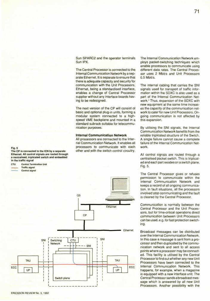
Fig. 5 The CP is connected to the ICN by a separate Ethernet. All control signals are routed through a centralised, triplicated switch and embedded in the traffic signal
CTU Control Termination Unit I Traffic signal
Control signal
Sun SPARC2 and the operator terminals Sun IPX.
The Central Processor is connected to the Internal Communication Network by a separate Ethernet. It is separate to ensure that there is adequate capacity and security for communication with the Unit Processors. Ethernet, being a standardised interface, enables a change of Central Processor supplier without any interface boards having to be redesigned.
The next version of the CP will consist of basic and optional plug-in units, forming a modular system connected to a highspeed VME backplane and mounted in a standard subrack suitable for telecommunication purposes.
Internal Communication Network All processors are connected to the Internal Communication Network. It enables all processors to communicate with each other and with the switch control circuitry.
The Internal Communication Network employs packet-switching techniques which enable processors to communicate using different data rates. The Central Processor uses 2 Mbit/s and Unit Processors 0.5 Mbit/s.
The internal cabling that carries the SNI signals used for transport of traffic information within the SDXC is also used as a part of the Internal Communication Network." Thus, expansion of the SDXC with new equipment at the same time increases the capacity of the communication network to cater for new Unit Processors. Ongoing communication is not affected by this expansion.
By utilising the SNI signals, the Internal Communication Network benefits from the reliable triplicated structure of the Switch. A single failure cannot cause a complete failure of the Internal Communication Network.
All control signals are routed through a centralised packet switch. This is triplicated and each part resides on a switch plane, Fig. 5.
The Central Processor gives or refuses permission to communicate within the Internal Communication Network and keeps a record of all ongoing communication. In fault situations, all the processors involved stop communicating and the fault is cleared by the Central Processor.
Communication is normally between the Central Processor and the Unit Processors, but for time-critical operations direct communication between Unit Processors can be used, e.g. for fast protection switching.
Broadcast messages can be distributed over the Internal Communication Network. In this case a message is sent from a processor and then duplicated by the communication network and sent to all access points where a processor may be connected. This facility is utilised by the Central Processor to find out whether any new Unit Processors have been connected to the Internal Communication Network. This happens, for example, when a magazine is equipped with a new interface unit. The Central Processor sends a broadcast message which is answered by all new Unit Processors. Another possibility with the
ERICSSON REVIEW No. 3, 1992
72
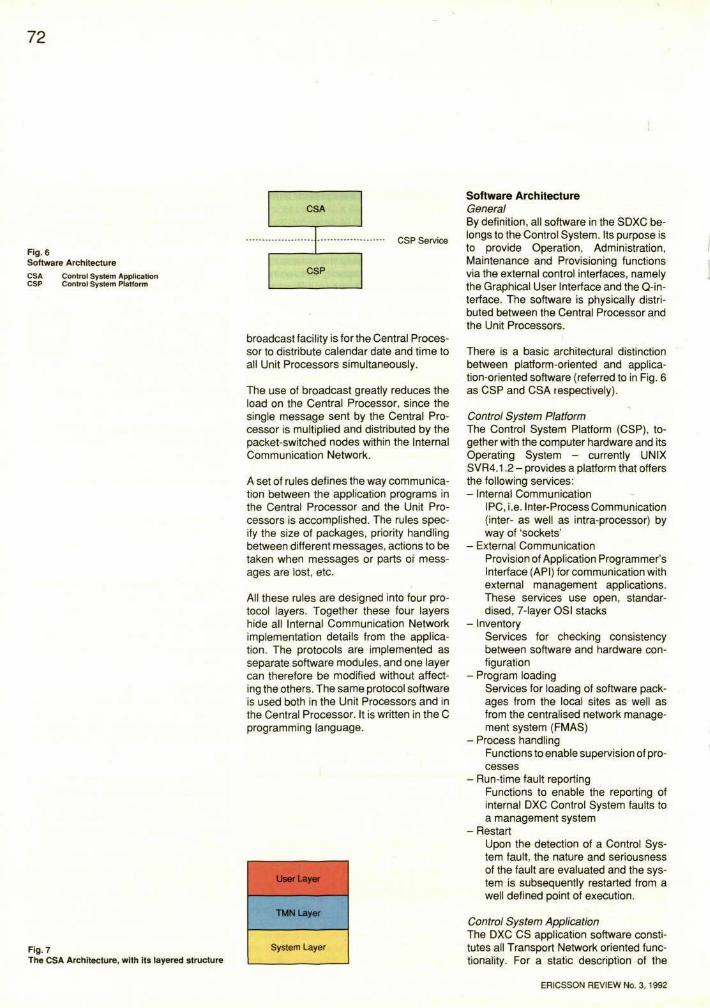
Fig. 6 Software Architecture
CSA CSP
Control System Application Control System Platform
broadcast facility is for the Central Processor to distribute calendar date and time to all Unit Processors simultaneously.
The use of broadcast greatly reduces the load on the Central Processor, since the single message sent by the Central Processor is multiplied and distributed by the packet-switched nodes within the Internal Communication Network.
A set of rules defines the way communication between the application programs in the Central Processor and the Unit Processors is accomplished. The rules specify the size of packages, priority handling between different messages, actions to be taken when messages or parts of messages are lost, etc.
All these rules are designed into four protocol layers. Together these four layers hide all Internal Communication Network implementation details from the application. The protocols are implemented as separate software modules, and one layer can therefore be modified without affecting the others. The same protocol software is used both in the Unit Processors and in the Central Processor. It is written in the C programming language.
Fig. 7 The CSA Architecture, with its layered structure
Software Architecture General By definition, all software in the SDXC belongs to the Control System. Its purpose is to provide Operation, Administration, Maintenance and Provisioning functions via the external control interfaces, namely the Graphical User Interface and the Q-in-terface. The software is physically distributed between the Central Processor and the Unit Processors.
There is a basic architectural distinction between platform-oriented and application-oriented software (referred to in Fig. 6 as CSP and CSA respectively).
Control System Platform The Control System Platform (CSP), together with the computer hardware and its Operating System - currently UNIX SVR4.1.2 - provides a platform that offers the following services: - Internal Communication
IPC, i.e. Inter-Process Communication (inter- as well as intra-processor) by way of 'sockets'
- External Communication Provision of Application Programmer's Interface (API) for communication with external management applications. These services use open, standardised, 7-layer OSI stacks
- Inventory Services for checking consistency between software and hardware configuration
- Program loading Services for loading of software packages from the local sites as well as from the centralised network management system (FMAS)
- Process handling Functions to enable supervision of processes
- Run-time fault reporting Functions to enable the reporting of internal DXC Control System faults to a management system
- Restart Upon the detection of a Control System fault, the nature and seriousness of the fault are evaluated and the system is subsequently restarted from a well defined point of execution.
Control System Application The DXC CS application software constitutes all Transport Network oriented functionality. For a static description of the
ERICSSON REVIEW No. 3, 1992
73
CSA, three aspects of the functionality are taken into account, thereby creating a layered structure, in order to isolate different dependencies and stimulate a modular design, Fig. 7. - The User Layer
contains the functionality of the Graphical User Interface. This layer of software will develop and change considerably due to different market needs and new tools for graphical presentation. It is therefore separated from the underlying software by an interface called the Controller Interface (CI) which can be said to represent the functionality provided by the TMN Layer and offered to management systems, such as centralised OS or local GUI
- The TMN Layer consists of functions for managing Network Elements specified in an object-oriented Information Model. An Information Model is becoming the standard way of specifying the manageable resources of a Network Element in the Transport Network. CCITT Recommendation G.774 describes the basis for the SDH NE Information Model, and thus forms the foundation for the DXC CS Telecommunication Management Layer (TMN). It will necessarily develop over the years, particularly since different
customers will require their SDH NE deployment in stages not coherent with CCITT Recommendation G.774 releases. For the purpose of isolating these dependencies, the Information Model aspects are singled out in the TMN Layer
- The System Layer For SDH NEs, CCITT Recommendations G.781-G.783 specify-through the use of Functional Block descriptions -the functionality that must be provided. The descriptions are a reasonably stable set of requirements and are singled out in the DXC CS in the System Layer so as to be distinguished from the management aspects. The object-oriented approach is used here too, i.e. the System Layer consists of a number of objects.
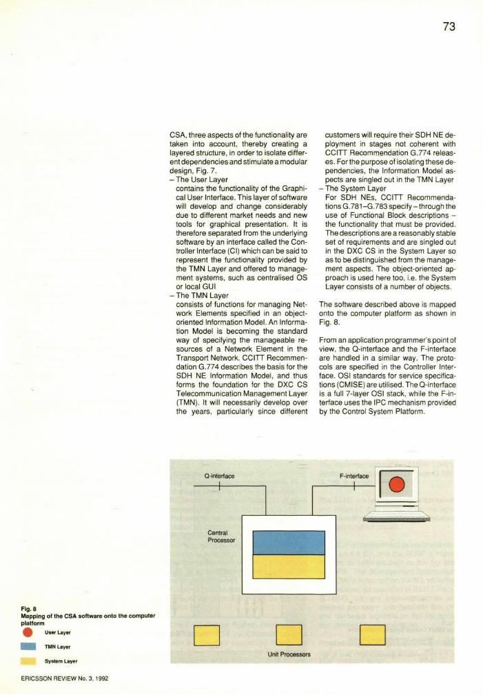
The software described above is mapped onto the computer platform as shown in Fig. 8.
From an application programmer's point of view, the Q-interface and the F-interface are handled in a similar way. The protocols are specified in the Controller Interface. OSI standards for service specifications (CMISE) are utilised. The Q-interface is a full 7-layer OSI stack, while the F-interface uses the IPC mechanism provided by the Control System Platform.
Fig. 8 Mapping of the CSA software onto the computer platform
74
Functional requirements Certain DXC Control System functional requirements must be taken into account when designing the software: - Several users
A DXC may be equipped with more than one GUI plus a Q-interface, and all of these interfaces must be able to operate simultaneously. This requires concurrency, which is implemented through several processes working on the objects (the MIB)
- Real-time characteristics The DXC Control System must be event-driven, in the sense that alarm detection mechanisms and subsequent evaluation and filtering are in some cases required to result in autonomous reconfigurations within a certain time
- Data storage and consistency The information in the objects contained in the MIB - representing everything of relevance to the management system -adds up to a considerable amount of data, the volume of which requires the use of disk storage. The information on the disk is also used for backup purposes. Typically, 1 GByte is used in a normal configuration. Since the MIB is the image used by the management system to represent the Network Element's manageable resources, it is of course of
extreme importance that the data is consistent with the current configuration
- Availability and robustness It is through the DXC Control System that a management system exerts its network control. This control might for example involve the setting up of a digital path through the Transport Network to provide end-users with data communication capacity. Unless the DXC CS has very high availability - a system which is robust, i.e. resistant to faults - the end-users will not receive their services, which ultimately leads to reduced revenues for the network operator.
Since different operators are allowed to operate the system simultaneously, it is essential to ensure that a consistent MIB is maintained. The operations are regarded as one or several transactions. Should a system fault occur, preventing a transaction from being carried out, a roll-back to a well defined state is performed. This means, in some cases, that part of the MIB must be locked during a Transaction. What constitutes a Transaction and what has to be locked is the responsiblity of the TMN Agent functionality.
Also, to allow for the shortest possible reaction times, i.e. to provide the event-driv-
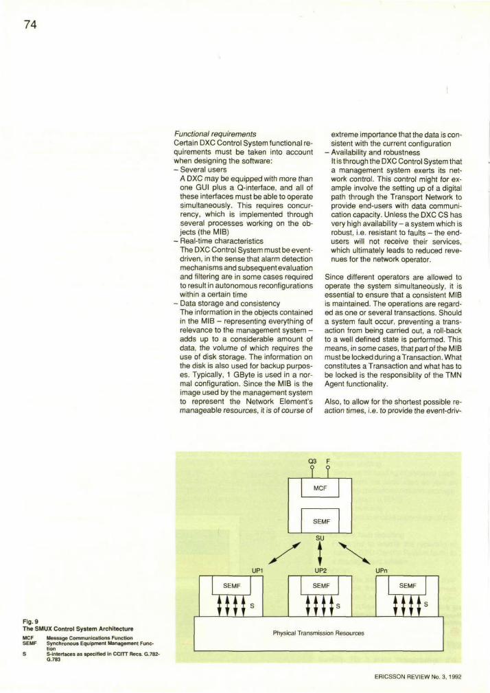
Fig. 9 The SMUX Control System Architecture
MCF Message Communications Function SEMF Synchronous Equipment Management Func
tion S S-interfaces as specified in CCITT Recs. G.782-
G.783
ERICSSON REVIEW No. 3, 1992
75
en real-time functionality, lengthy executions must be divided into Transactions.
Data related to the Information Model can be stored by using one of several possible techniques: - Object DataBase Management System,
ODBMS This solution is very attractive in the sense that it provides persistent objects, which is exactly what the Information Model specification suggests. The difference between the implementation of the system and the way it is described in an Information Model is less than in the other solutions. Also, the amount of design and implementation work is considerably less
- Relational Data-Base Management System, RDBMS This solution also limits the amount of design and implementation work because it provides mechanisms - such as an ODBMS - for data storage, transaction handling, roll-back, etc. However, a translation (design) must be made from the object-oriented specification to the world of tables in a relational database
- Ordinary files This solution is 'the hacker's choice'. It is straightforward in that it uses only what the Operating System and the programming language provide
- Class library This represents something of a compromise. It provides basic data persistence functionality for objects.
Implementation Structure The network resource represented by a Managed Object is partly implemented in hardware, and the software is divided between the Central Processor and Unit Processors. To utilise the distributed processor structure, which in a DXC of normal size means one CP and some 100 UPs or more, as much as possible of the functionality is delegated to the UPs. The Internal Communication Network, ICN, allows UPs to communicate directly without involving the CP, which means that real-time functions such as protection switching and network synchronisation can be handled in the UPs.
The DXC Control System developed for the German PTT by Ericsson together with the German companies FUBA and DeTeWe - its partners in the FLEXNODE consortium, which will install AXD 4/1 and
AXD 1/0 in 6 sites - is regarded as a prototype system and does not show all the characteristics mentioned as requirements above.
SMUX CONTROL SYSTEM ARCHITECTURE General The SMUX Control System is implemented mainly by programs executed on a Central Processor (the Support Unit) as well as Unit Processors (UPs) distributed on each transmission printed board assembly within the NE. The SU is a one-board processor common to the whole range of Ericsson SDH multiplexers and optimised for small NEs. The SU may be common to a number - normally two - of SDH multiplexers.
The SU has an overall responsibility for management of the NE and receives and evaluates management operations issued from an OS or a local operator. As a response to events detected in the network, the SU issues notifications, e.g. alarm messages, to the OS. The Q3 and ECC protocol suites, and the F-interface, are also controlled by the SU.
Functions of a simple nature but with a high repetition rate, e.g. scanning of binary indications, alarms, calculation of PM parameters and operations in close connection with transmission hardware, are performed by UPs.
The implementation of the SMUX Control System mapped onto CCITT Recs. G.782-G.783, is shown in Fig. 9.
The SEMF is a function block which sends and receives data on low-level management functions to and from transmission-oriented function blocks.
The MCF is implemented as a protocol machine on the SU, and the SEMF is implemented as software both on the SU and on UPs. The Management Information Base (MIB) is located on the SU, while the S-interfaces, as specified in CCITT Recs. G.782-G.783, are implemented as an internal processor bus between the UP and hardware registers on the transmission printed board assemblies.
Commercially available products supplied by Retix are used to implement the Q3 and ECC protocol suites.
76
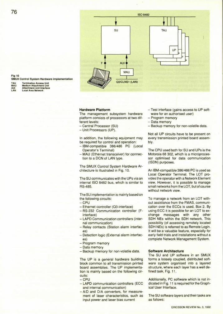
Fig 10 SMUX Control System Hardware implementation
TAU Termination Access Unit MAU Medium Attachment Unit AUI Attachment Unit Interface LAN Local Area Network
Hardware Platform The management subsystem hardware platform consists of processors at two different levels: - Central Processor (SU) - Unit Processors (UP).
In addition, the following equipment may be required for control and operation: - IBM-compatible 386/486 PC (Local
Operator's Terminal) - MAU (Ethernet transceiver) for connec
tion to a DCN of LAN type.
The SMUX Control System Hardware Architecture is illustrated in Fig. 10.
The SU communicates with the UPs via an internal ISO 8482 bus, which is similar to RS-485.
The SU implementation is mainly based on the following circuits: - C P U - Ethernet controller (Q3-interface) - RS-232 Communication controller (F-
interface) - LAPD Communication controllers (inter
nal communication) - Relay contacts (Station alarm interfac
es) - Detection logic (External alarm interfac
es) - Program memory - Data memory - Backup memory for non-volatile data.
The UP is a general hardware building block common to all transmission printed board assemblies. The UP implementation is mainly based on the following circuits: - C P U - LAPD communication controllers (ECC
and internal communication) - A/D and D/A converters, for measure
ment of laser characteristics, such as input power and laser bias current
- Test interface (gains access to UP software for an authorised user)
- Program memory - Data memory - Backup memory for non-volatile data.
Not all UP circuits have to be present on every transmission printed board assembly.
The CPU used both for SU and UPs is the Motorola 68 302, which is a microprocessor optimised for data communication (ISDN) purposes.
An IBM-compatible 386/486 PC is used as Local Operator Terminal. The LOT provides the operator with a Network Element view. However, it is possible to manage small networks from the LOT, but of course without network view.
To manage a network from an LOT without assistance from the FMAS, communication over the ECCs is used, Box 2. By using ECC it is possible for an LOT to exchange messages with any other SDH NEs within the SDH network. This possibility (of accessing remotely located SDH NEs) is referred to as Remote Login. It will be a valuable feature, especially for early field trials and installations without a complete Network Management System.
Software Architecture The SU and UP software in an SMUX forms a loosely coupled, distributed software system organised into a layered structure, where each layer has a well defined task, Fig. 11.
Additionally, PC software which is not indicated in Fig. 11 is required for the Graphical User Interface.
The SU software layers and their tasks are as follows:
ERICSSON REVIEW No. 3, 1992
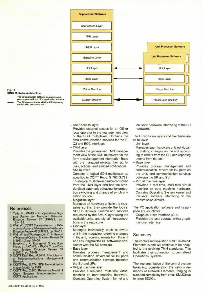
Fig. 11 SMUX Software Architecture
• The SU application software communicates peer-to-peer with the UP's application software
• » The SU communicates with the UP's by using an ISO 8482 backplane bus
References 1 Tarle, H.: FMAS - An Operations Sup
port System for Transport Networks. Ericsson Review 67 (1990):2, pp. 163-182.
2 Widl.W.: CCITTStandardisation of Telecommunications Management Networks Ericsson Review 68 (1991) :2, pp. 34-51.
3 Widl, W. and Woldegiorgis, K.: In Search of Managed Objects. Ericsson Review 69 (1992):1/2, pp. 34-56.
4 Bergkvist, J. A., Evangelisti, G. and Hop-finger, J.: AXD 4/1, a Digital Cross-Connect System. Ericsson Review 69 (1992):3, pp. 78-68.
5 CCITT Draft Rec. M.3010: Principles for a Telecommunications Management Network.
6 CCITT Rec. G.774: SDH Network Information Model for TMN
7 CCITT Rec. X.200; Reference Model of Open Systems Interconnection for CCITT Applications.
- User Access layer Provides external access for an OS or local operator to the management view of the SDH multiplexer. Contains the data communication services for the F, Q3 and ECC interfaces
• TMN layer Provides the generalised TMN management view of the SDH multiplexer in the form of a Management Information Base with the managed objects, their attributes, actions, and emitted notifications
• SMUX layer Contains a logical SDH multiplexer as specified in CCITT Recs. G.782-G.783. This logical multiplexer can be controlled from the TMN layer and has the standardised automatic behaviour for protection switching and change of synchronisation source
- Magazine layer Manages all hardware units in the magazine so that they provide the logical SDH multiplexer transmission services requested by the SMUX layer using the available units, and signal interconnections in the magazine
- Unit layer Manages individually each hardware unit in the magazine, ordering changes in the unit, receiving events from the unit and ensuring that the U P software is consistent with the SU software
- Base layer Provides process management and communication, drivers for SU I/O ports and communication services between the SU and UPs
- Virtual machine layer Provides a real-time, multi-task virtual machine on bare machine hardware. Contains Operating System kernel and
low-level hardware interfacing to the SU hardware.
The UP software layers and their tasks are as follows: - Unit layer
Manages each hardware unit individually, making changes on the unit according to orders from the SU, and reporting events from the unit
- Base layer Provides process management and communication, drivers for I/O ports on the unit, and communication services between the UP and SU
- Virtual machine layer Provides a real-time, multi-task virtual machine on bare machine hardware. Contains Operating System kernel and low-level software interfacing to the transmission circuits.
The PC application software and its purpose are as follows: - Graphical User Interface (GUI)
Provides the local operator with a graphical user interface.
Summary The control and operation of SDH Network Elements is and will continue to be adapted to the evolving TMN standards. This facilitates their connection to centralised Operations Systems.
The implementation of the control system takes into consideration the various demands of Network Elements, ranging in size and complexity from small SMUXs up to large SDXCs.
ERICSSON REVIEW No. 3, 1992
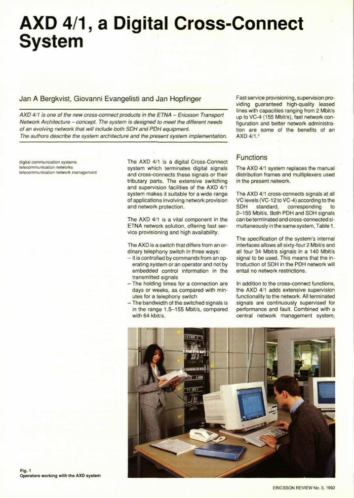
AXD 4/1, a Digital Cross-Connect System
Jan A Bergkvist, Giovanni Evangelisti and Jan Hopfinger
AXD 4/1 is one of the new cross-connect products in the ETNA - Ericsson Transport Network Architecture - concept. The system is designed to meet the different needs of an evolving network that will include both SDH and PDH equipment. The authors describe the system architecture and the present system implementation.
Fast service provisioning, supervision providing guaranteed high-quality leased lines with capacities ranging from 2 Mbit/s up to VC-4 (155 Mbit/s), fast network configuration and better network administration are some of the benefits of an AXD 4/1.3
digital communication systems telecommunication networks telecommunication network management
The AXD 4/1 is a digital Cross-Connect system which terminates digital signals and cross-connects these signals or their tributary parts. The extensive switching and supervision facilities of the AXD 4/1 system makes it suitable for a wide range of applications involving network provision and network protection.
The AXD 4/1 is a vital component in the ETNA network solution, offering fast service provisioning and high availability.
The AXD is a switch that differs from an ordinary telephony switch in three ways: - It is controlled by commands from an op
erating system or an operator and not by embedded control information in the transmitted signals
- The holding times for a connection are days or weeks, as compared with minutes for a telephony switch
- The bandwidth of the switched signals is in the range 1.5-155 Mbit/s, compared with 64 kbit/s.
Functions The AXD 4/1 system replaces the manual distribution frames and multiplexers used in the present network.
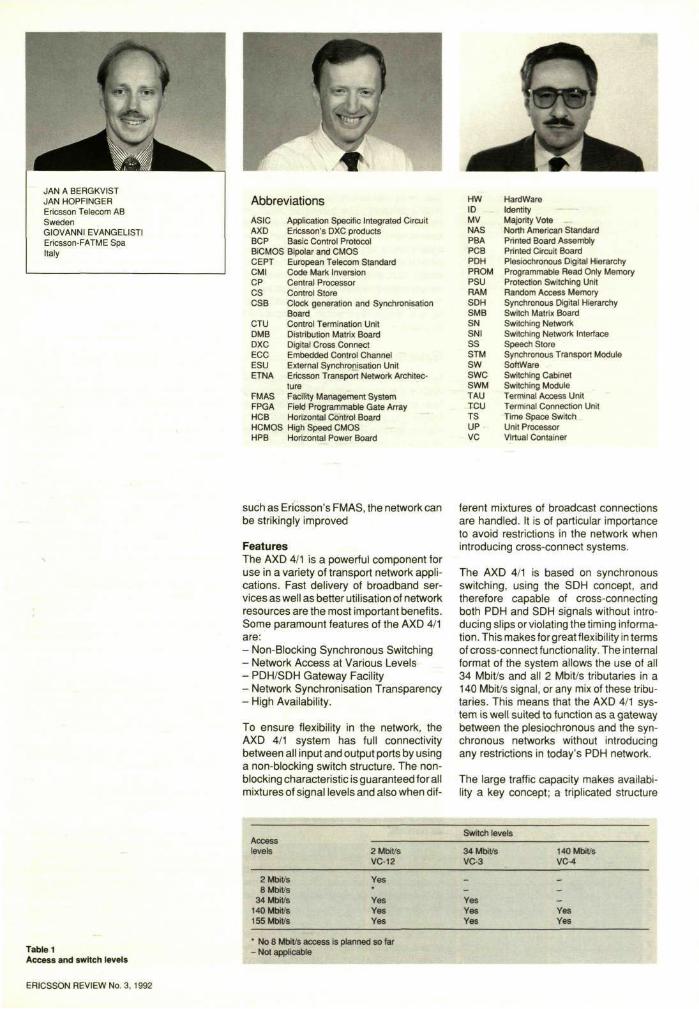
The AXD 4/1 cross-connects signals at all VC levels (VC-12 to VC-4) according to the SDH standard, corresponding to 2-155 Mbit/s. Both PDH and SDH signals can be terminated and cross-connected simultaneously in the same system, Table 1.
The specification of the system's internal interfaces allows all sixty-four 2 Mbit/s and all four 34 Mbit/s signals in a 140 Mbit/s signal to be used. This means that the introduction of SDH in the PDH network will entail no network restrictions.
In addition to the cross-connect functions, the AXD 4/1 adds extensive supervision functionality to the network. All terminated signals are continuously supervised for performance and fault. Combined with a central network management system,
Fig. 1 Operators working with the AXD system
ERICSSON REVIEW No. 3, 1992
Abbreviations
ASIC AXD BCP
Application Specific Integrated Circuit Ericsson's DXC products Basic Control Protocol
BiCMOS Bipolar and CMOS CEPT CMI CP CS CSB
CTU DMB DXC ECC ESU ETNA
FMAS FPGA HCB HCMOS HPB
European Telecom Standard Code Mark Inversion Central Processor Control Store Clock generation and Synchronisation Board Control Termination Unit Distribution Matrix Board Digital Cross Connect Embedded Control Channel External Synchronisation Unit Ericsson Transport Network Architecture Facility Management System Field Programmable Gate Array Horizontal Control Board High Speed CMOS Horizontal Power Board
HW ID MV NAS PBA PCB PDH PROM PSU RAM SDH SMB SN SNI SS STM
sw swc SWM TAU TCU TS UP VC
Hardware Identity Majority Vote North American Standard Printed Board Assembly Printed Circuit Board Plesiochronous Digital Hierarchy Programmable Read Only Memory Protection Switching Unit Random Access Memory Synchronous Digital Hierarchy Switch Matrix Board Switching Network Switching Network Interface Speech Store Synchronous Transport Module Software Switching Cabinet Switching Module Terminal Access Unit Terminal Connection Unit Time Space Switch Unit Processor Virtual Container
such as Ericsson's FMAS, the network can be strikingly improved
Features The AXD 4/1 is a powerful component for use in a variety of transport network applications. Fast delivery of broadband services as well as better utilisation of network resources are the most important benefits. Some paramount features of the AXD 4/1 are: - Non-Blocking Synchronous Switching - Network Access at Various Levels - PDH/SDH Gateway Facility - Network Synchronisation Transparency - High Availability.
To ensure flexibility in the network, the AXD 4/1 system has full connectivity between all input and output ports by using a non-blocking switch structure. The non-blocking characteristic is guaranteed for all mixtures of signal levels and also when dif
ferent mixtures of broadcast connections are handled. It is of particular importance to avoid restrictions in the network when introducing cross-connect systems.
The AXD 4/1 is based on synchronous switching, using the SDH concept, and therefore capable of cross-connecting both PDH and SDH signals without introducing slips or violating the timing information. This makes for great flexibility in terms of cross-connect functionality. The internal format of the system allows the use of all 34 Mbit/s and all 2 Mbit/s tributaries in a 140 Mbit/s signal, or any mix of these tributaries. This means that the AXD 4/1 system is well suited to function as a gateway between the plesiochronous and the synchronous networks without introducing any restrictions in today's PDH network.
The large traffic capacity makes availability a key concept; a triplicated structure
JAN A BERGKVIST JAN HOPFINGER Ericsson Telecom AB Sweden GIOVANNI EVANGELISTI Ericsson-FATME Spa Italy
Table 1 Access and switch levels
ERICSSON REVIEW No. 3, 1992
80
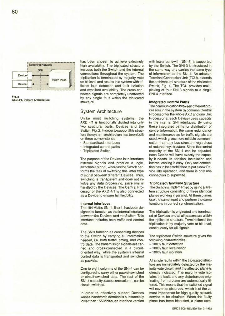
Fig. 2 AXD 4/1, System Architecture
has been chosen to achieve extremely high availability. The triplicated structure includes both the Switch and the internal connections throughout the system. The triplication is terminated by majority vote on bit level and results in a system with efficient fault detection and fault isolation and excellent availability. The cross-connected signals are completely unaffected by any single fault within the triplicated structure.
System Architecture Unlike most switching systems, the AXD 4/1 is functionally divided into only two structural parts, Devices and the Switch, Fig. 2. In order to support this structure the system architecture has been built on three corner-stones: - Standardised interfaces - Integrated control paths - Triplicated Switch.
The purpose of the Devices is to interface external signals and produce a logic, switchable signal, whereas the Switch performs the task of switching this latter type of signal between different Devices. Thus, switching is transparent and does not involve any data processing, since this is handled by the Devices. The Central Processor of the AXD 4/1 is also connected as a Device to ensure full flexibility.
Internal Interfaces The 184 Mbit/s SNI-4, Box 1, has been designed to function as the internal interface between the Devices and the Switch. This interface includes both traffic and control data.
The SNIs function as connecting-devices to the Switch by carrying all information needed, i.e. both traffic, timing, and control data. The transmission signals are carried and cross-connected in a circuit-oriented way, while the system's internal control data is transported and switched as packets.
One to eight columns of the SNI-4 can be configured to carry either packet-switched or circuit-switched data. The rest of the SNI-4 capacity, except one column, can be circuit-switched.
In order to effectively support Devices whose bandwidth demand is substantially lower than 155 Mbit/s, an interface version
with lower bandwith (SNI-3) is supported by the Switch. The SNI-3 is structured in the same way and carries the same type of information as the SNI-4. An adaptor, Terminal Connection Unit (TCU), extends the architectural structure of the triplicated Switch, Fig. 4. The TCU provides multiplexing of four SNI-3 signals to a single SNI-4 interface.
Integrated Control Paths The communication between different processors in the system (a common Central Processor for the whole AXD and one Unit Processor at each Device) uses capacity in the internal SNI interfaces. By using these integrated paths for distribution of control information, the same redundancy and maintenance as for traffic signals are used, which gives more reliable communication than any bus structure regardless of redundancy structure. Since the control capacity of the SNI-4 can be adjusted, each Device will have exactly the capacity it needs. In addition, installation and internal cabling is easy. Only one connection has to be established to put a new Device into operation, and there is only one connection to supervise.
Triplicated Hardware Structure The Switch is implemented by using a system structure consisting of three identical planes working in parallel. All three planes use the same input and perform the same functions in perfect synchronisation.
The triplication is originated and terminated at Devices and at all processors within the triplicated structure. Termination of the triplication is by majority vote at bit level, continuously for all signals.
The triplicated Switch structure gives the following characteristics: - 100% fault detection - 100% fault localisation - 1 0 0 % fault isolation.
All single faults within the triplicated structure are immediately detected by the majority vote circuit, and the affected plane is directly indicated. The majority vote isolates the fault, and any disturbances originating from a plane are automatically filtered. This means that the switched signal will never be disturbed, which is of the utmost importance for high-quality network service to be obtained. When the faulty plane has been identified, a plane com-
ERICSSON REVIEW No. 3, 1992
81
parison/majority vote is performed on sec- Processor distribution tions of the planes to indicate the faulty The Control System in AXD 4/1 consists board. of one common Central Processor (CP) for
the whole AXD and one Unit Processor Triplication results in a more robust (UP) at each Device, i.e one board or a system, with less complex maintenance Switch plane. The CP performs all control functionality compared with that of a dupli- functions and handles the communication cated system, and makes it easier to up- to/from FMAS via a Q-interface. The CP grade functionality in the future. can be a redundant or single machine with
ERICSSON REVIEW No. 3, 1992
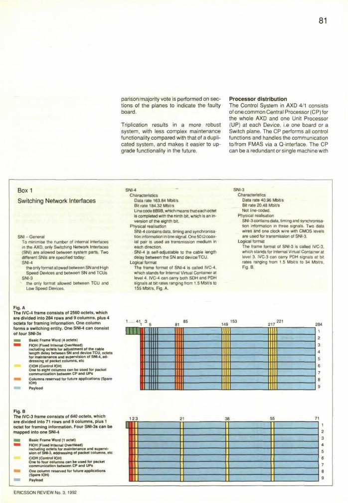
Box 1
Switching Network Interfaces
SNI - General To minimise the number of internal interfaces in the AXD, only Switching Network Interfaces (SNI) are allowed between system parts. Two different SNIs are specified today. SNI-4
the only format allowed between SN and High Speed Devices and between SN and TCUs
SNI-3 the only format allowed between TCU and Low Speed Devices.
SNI-4 Characteristics
Data rate 163.84 Mbit/s Bit rate 184.32 Mbit/s Line code 8B9B, which means that each octet is completed with the ninth bit, which is an inversion of the eighth bit.
Physical realisation SNI-4 contains data, timing and synchronisation information in one signal. One 50 ficoax-ial pair is used as transmission medium in each direction. SNI-4 is self-adjustable to the cable length delay between the SN and device/TCU.
Logical format The frame format of SNI-4 is called IVC-4, which stands for Internal Virtual Container at level 4. IVC-4 can carry both SDH and PDH signals at bit rates ranging from 1.5 Mbit/s to 155 Mbit/s, Fig. A.
SNI-3 Characteristics
Data rate 40.96 Mbit/s Bit rate 20.48 Mbit/s Not line-coded.
Physical realisation SNI-3 contains data, timing and synchronisation information in three signals. Two data wires and one clock wire with CMOS levels are used for transmission of SNI-3.
Logical format The frame format of SNI-3 is called IVC-3, which stands for Internal Virtual Container at level 3. IVC-3 can carry PDH signals at bit rates ranging from 1.5 Mbit/s to 34 Mbit/s, Fig. B.
Fig. A The IVC-4 frame consists of 2560 octets, which are divided into 284 rows and 9 columns, plus 4 octets for framing information. One column forms a switching entity. One SNI-4 can consist of four SNI-3s
Fig. B The IVC-3 frame consists of 640 octets, which are divided into 71 rows and 9 columns, plus 1 octet for framing information. Four SNI-3s can be mapped into one SNI-4
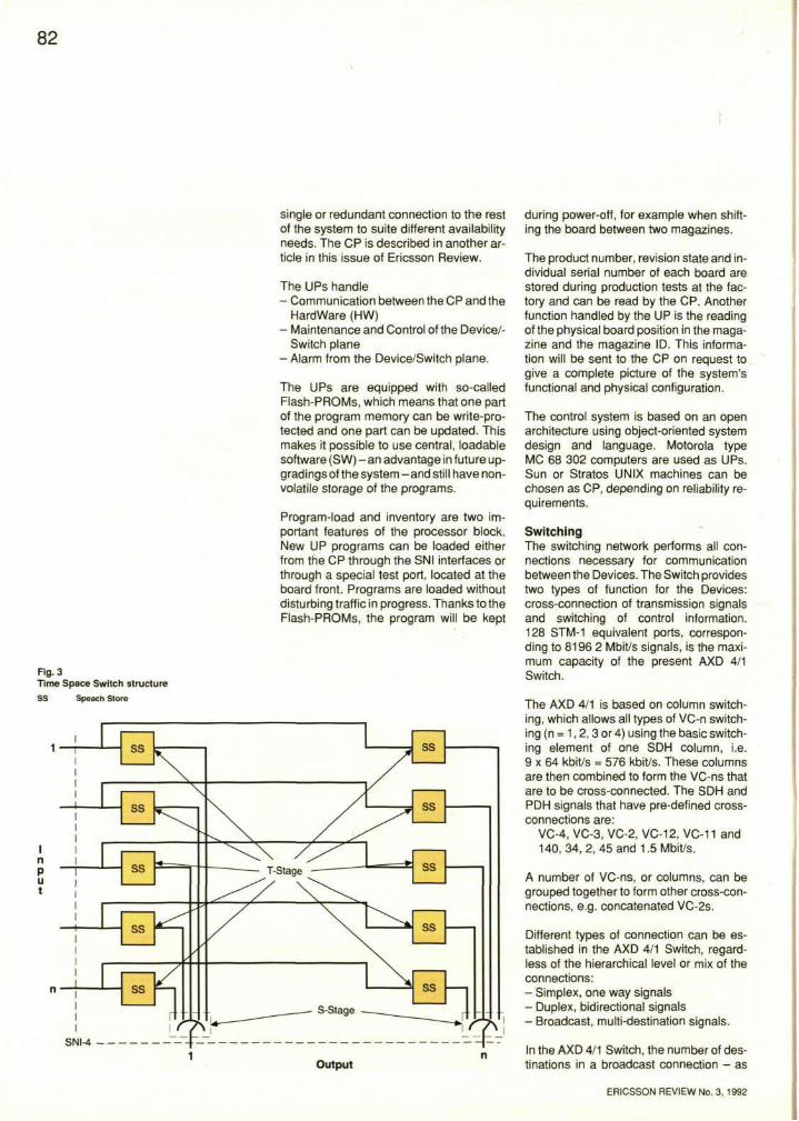
82
Fig. 3 Time Space Switch structure
SS Speach Store
single or redundant connection to the rest of the system to suite different availability needs. The CP is described in another article in this issue of Ericsson Review.
The UPs handle - Communication between the CP and the
Hardware (HW) - Maintenance and Control of the Device/-
Switch plane - Alarm from the Device/Switch plane.
The UPs are equipped with so-called Flash-PROMs, which means that one part of the program memory can be write-pro-tected and one part can be updated. This makes it possible to use central, loadable software (SW) - a n advantage in future up-gradings of the system - and still have nonvolatile storage of the programs.
Program-load and inventory are two important features of the processor block. New UP programs can be loaded either from the CP through the SNI interfaces or through a special test port, located at the board front. Programs are loaded without disturbing traffic in progress. Thanks to the Flash-PROMs, the program will be kept
during power-off, for example when shifting the board between two magazines.
The product number, revision state and individual serial number of each board are stored during production tests at the factory and can be read by the CP. Another function handled by the UP is the reading of the physical board position in the magazine and the magazine ID. This information will be sent to the CP on request to give a complete picture of the system's functional and physical configuration.
The control system is based on an open architecture using object-oriented system design and language. Motorola type MC 68 302 computers are used as UPs. Sun or Stratos UNIX machines can be chosen as CP, depending on reliability requirements.
Switching The switching network performs all connections necessary for communication between the Devices. The Switch provides two types of function for the Devices: cross-connection of transmission signals and switching of control information. 128 STM-1 equivalent ports, corresponding to 8196 2 Mbit/s signals, is the maximum capacity of the present AXD 4/1 Switch.
The AXD 4/1 is based on column switching, which allows all types of VC-n switching (n = 1,2,3 or 4) using the basic switching element of one SDH column, i.e. 9 x 64 kbit/s = 576 kbit/s. These columns are then combined to form the VC-ns that are to be cross-connected. The SDH and PDH signals that have pre-defined cross-connections are:
VC-4, VC-3, VC-2, VC-12, VC-11 and 140, 34, 2, 45 and 1.5 Mbit/s.
A number of VC-ns, or columns, can be grouped together to form other cross-connections, e.g. concatenated VC-2s.
Different types of connection can be established in the AXD 4/1 Switch, regardless of the hierarchical level or mix of the connections: - Simplex, one way signals - Duplex, bidirectional signals - Broadcast, multi-destination signals.
In the AXD 4/1 Switch, the number of destinations in a broadcast connection - as
ERICSSON REVIEW No. 3, 1992
83
well as the number of simultaneous broadcast connections - is unlimited. This means that an AXD 4/1 Switch is suitable for services on leased or switched circuits from 1.5 Mbit/s up to 140/155 Mbit/s.
SNI-4 column, the basic switching entity An SNI-4 column, 9 x 64 kbit/s, is the smallest possible switchable entity. The bandwidth of one SNI-4 column is regarded as sufficiently small for internal applications too.
Each external signal terminated by the AXD 4/1 and each standard tributary of that signal is mapped into an integer number of columns. As a maximum, a whole STM-1 channel (155 Mbit/s) including overhead (OH) can be switched.
To be able to provide connections that use a number of columns, the integrity of the frame of columns is guaranteed, i.e. the time sequence integrity.
Non-blocking, full connectivity Switch matrix The Switch matrix is designed to provide circuit-switched connections without any internal congestion and to ensure full connectivity between any input and any output port, independently of the hierarchical level of the cross-connected signals and of the mix of hierarchies (CEPT, NAS, SDH, simplex, broadcast).
The Switch is a Time-Space-switch (TS) consisting of a number of Speech Stores (SS), arranged in rows and columns: one row for each input and one column for each output, Fig. 3.
Every time a signal is to be fed to a certain output, it can be chosen from among the signals stored in one of the SS (n) associated exclusively with that output. The choice is made through the use of Control Stores (CS) associated with that same output.
No switch action will affect connections already established.
Characteristics of the TS structure Since no internal routing is necessary and only one T-stage is involved, the TS switch has the following characteristics: - No rearrangement of established con
nections is needed to permit the set-up
of a new connection, capable of being used for broadcast also
- The delay introduced by the switch is minimised.
This results in a switch with short set-up time and very low transmission delay, which is necessary in a large network with stringent service requirements.
Multicolumn switching Multiconnection switching is characterised by the connection of a number of columns executed at the same time. The number of columns that can be connected in a multi-connect switching operation has no upper limit. As an extreme, the whole switch can be reconfigured at the same time.
Internal communication The AXD 4/1 Switch is capable of handling packet-oriented signals. This function is used both for internal control communication and to handle Embedded Communication Channels (ECC) in SDH signals. A special communication protocol is developed to handle the internal communication - the Basic Communication Protocol (BCP). BCP is a self-addressing protocol that uses the tree-structure of the integrated control paths to give reliable internal communication. Information is carried in 'packet format'. The packet-handling equipment and the circuit switch are triplicated, so as to fulfil general requirements for failure immunity and fault detection capability.
The supervision of internal communication is handled by BCP functionality and by the triplication.
Devices All types of equipment connected to the Switch are called Devices. The most common types are Termination Access Units (TAU), which terminate transmission signals. The Central Processor, too, is connected as a Device.
In addition to the termination of signals, i.e. line signal access and multiplexing, a Device terminates the switching network. Majority vote is used to terminate the signals from the triplicated Switch. This is the basic function that forms a single fault-tolerant system.
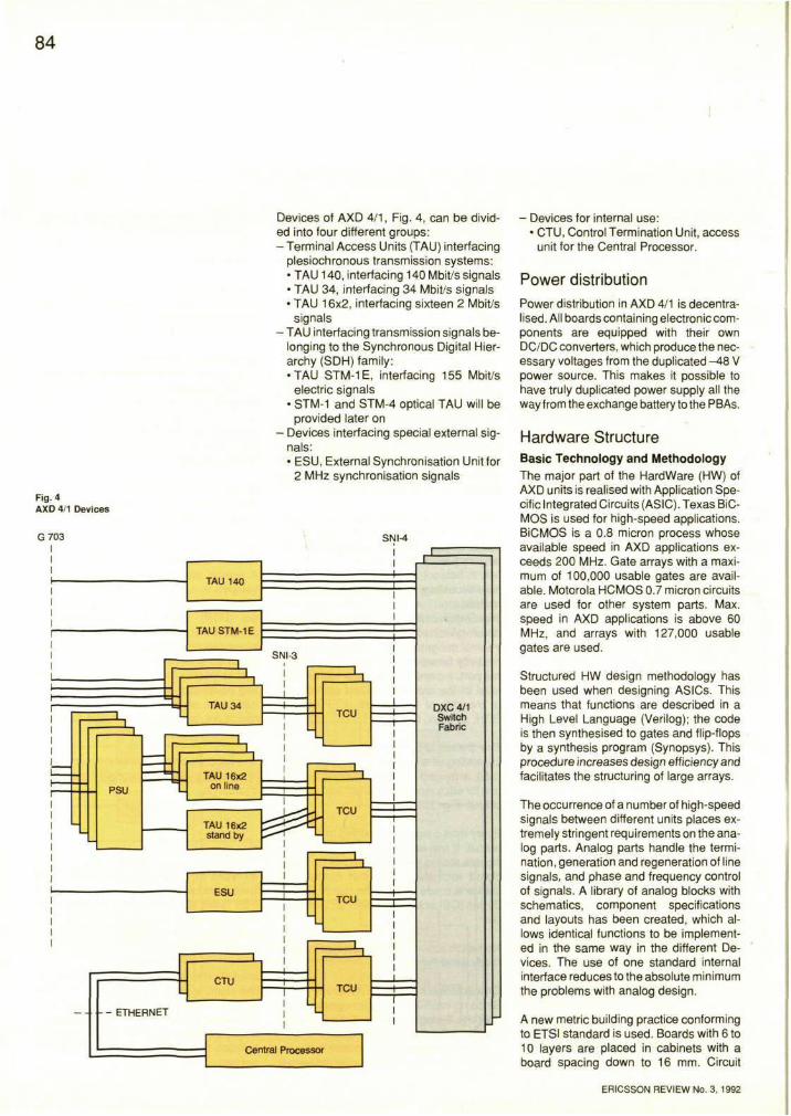
84
Fig. 4 AXD 4/1 Devices
Devices of AXD 4/1, Fig. 4, can be divided into four different groups: - Terminal Access Units (TAU) interfacing
plesiochronous transmission systems: • TAU 140, interfacing 140 Mbit/s signals • TAU 34, interfacing 34 Mbit/s signals • TAU 16x2, interfacing sixteen 2 Mbit/s
signals - TAU interfacing transmission signals be
longing to the Synchronous Digital Hierarchy (SDH) family: •TAU STM-1E, interfacing 155 Mbit/s
electric signals • STM-1 and STM-4 optical TAU will be
provided later on - Devices interfacing special external sig
nals: • ESU, External Synchronisation Unit for
2 MHz synchronisation signals
- Devices for internal use: • CTU, Control Termination Unit, access
unit for the Central Processor.
Power distribution Power distribution in AXD 4/1 is decentralised. All boards containing electronic components are equipped with their own DC/DC converters, which produce the necessary voltages from the duplicated -48 V power source. This makes it possible to have truly duplicated power supply all the way from the exchange battery to the PBAs.
Hardware Structure Basic Technology and Methodology The major part of the Hardware (HW) of AXD units is realised with Application Specific Integrated Circuits (ASIC). Texas BiC-MOS is used for high-speed applications. BiCMOS is a 0.8 micron process whose available speed in AXD applications exceeds 200 MHz. Gate arrays with a maximum of 100,000 usable gates are available. Motorola HCMOS 0.7 micron circuits are used for other system parts. Max. speed in AXD applications is above 60 MHz, and arrays with 127,000 usable gates are used.
Structured HW design methodology has been used when designing ASICs. This means that functions are described in a High Level Language (Verilog); the code is then synthesised to gates and flip-flops by a synthesis program (Synopsys). This procedure increases design efficiency and facilitates the structuring of large arrays.
The occurrence of a number of high-speed signals between different units places extremely stringent requirements on the analog parts. Analog parts handle the termination, generation and regeneration of line signals, and phase and frequency control of signals. A library of analog blocks with schematics, component specifications and layouts has been created, which allows identical functions to be implemented in the same way in the different Devices. The use of one standard internal interface reduces to the absolute minimum the problems with analog design.
A new metric building practice conforming to ETSI standard is used. Boards with 6 to 10 layers are placed in cabinets with a board spacing down to 16 mm. Circuit
ERICSSON REVIEW No. 3, 1992
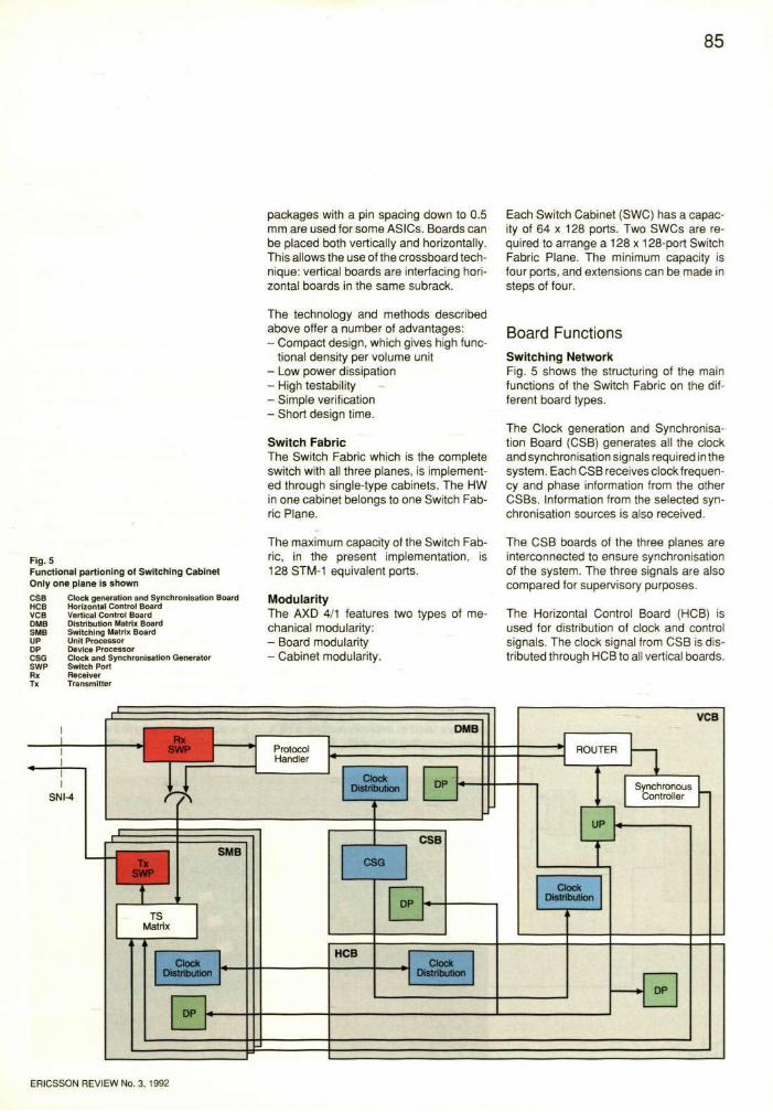
85
packages with a pin spacing down to 0.5 mm are used for some ASICs. Boards can be placed both vertically and horizontally. This allows the use of the crossboard technique: vertical boards are interfacing horizontal boards in the same subrack.
Each Switch Cabinet (SWC) has a capacity of 64 x 128 ports. Two SWCs are required to arrange a 128 x 128-port Switch Fabric Plane. The minimum capacity is four ports, and extensions can be made in steps of four.
The technology and methods described above offer a number of advantages: - Compact design, which gives high func
tional density per volume unit - Low power dissipation - High testability - Simple verification - Short design time.
Switch Fabric The Switch Fabric which is the complete switch with all three planes, is implemented through single-type cabinets. The HW in one cabinet belongs to one Switch Fabric Plane.
Board Functions Switching Network Fig. 5 shows the structuring of the main functions of the Switch Fabric on the different board types.
The Clock generation and Synchronisation Board (CSB) generates all the clock and synchronisation signals required in the system. Each CSB receives clock frequency and phase information from the other CSBs. Information from the selected synchronisation sources is also received.
Fig. 5 Functional partioning of Switching Cabinet Only one plane is shown CSB HCB VCB DMB SMB UP DP CSG SWP Rx Tx
Clock generation and Synchronisation Board Horizontal Control Board Vertical Control Board Distribution Matrix Board Switching Matrix Board Unit Processor Device Processor Clock and Synchronisation Generator Switch Port Receiver Transmitter
The maximum capacity of the Switch Fabric, in the present implementation, is 128STM-1 equivalent ports.
Modularity The AXD 4/1 features two types of mechanical modularity: - Board modularity - Cabinet modularity.
The CSB boards of the three planes are interconnected to ensure synchronisation of the system. The three signals are also compared for supervisory purposes.
The Horizontal Control Board (HCB) is used for distribution of clock and control signals. The clock signal from CSB is distributed through HCB to all vertical boards.
ERICSSON REVIEW No. 3, 1992
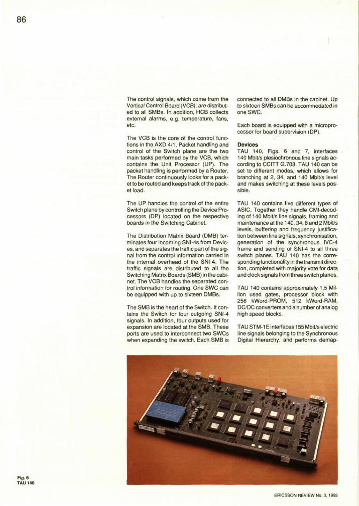
86
The control signals, which come from the Vertical Control Board (VCB), are distributed to all SMBs. In addition, HCB collects external alarms, e.g. temperature, fans, etc.
The VCB is the core of the control functions in the AXD 4/1. Packet handling and control of the Switch plane are the two main tasks performed by the VCB, which contains the Unit Processor (UP). The packet handling is performed by a Router. The Router continuously looks for a packet to be routed and keeps track of the packet load.
connected to all DMBs in the cabinet. Up to sixteen SMBs can be accommodated in one SWC.
Each board is equipped with a microprocessor for board supervision (DP).
Devices TAU 140, Figs. 6 and 7, interfaces 140 Mbit/s plesiochronous line signals according to CCITT G.703. TAU 140 can be set to different modes, which allows for branching at 2, 34, and 140 Mbit/s level and makes switching at these levels possible.
The UP handles the control of the entire Switch plane by controlling the Device Processors (DP) located on the respective boards in the Switching Cabinet.
The Distribution Matrix Board (DMB) terminates four incoming SNI-4s from Devices, and separates the traffic part of the signal from the control information carried in the internal overhead of the SNI-4. The traffic signals are distributed to all the Switching Matrix Boards (SMB) in the cabinet. The VCB handles the separated control information for routing. One SWC can be equipped with up to sixteen DMBs.
The SMB is the heart of the Switch. It contains the Switch for four outgoing SNI-4 signals. In addition, four outputs used for expansion are located at the SMB. These ports are used to interconnect two SWCs when expanding the switch. Each SMB is
TAU 140 contains five different types of ASIC. Together they handle CMI-decod-ing of 140 Mbit/s line signals, framing and maintenance at the 140,34,8 and 2 Mbit/s levels, buffering and frequency justification between line signals, synchronisation, generation of the synchronous IVC-4 frame and sending of SNI-4 to all three switch planes. TAU 140 has the corresponding functionality in the transmit direction, completed with majority vote for data and clock signals from three switch planes.
TAU 140 contains approximately 1.5 Million used gates, processor block with 256 kWord-PROM, 512 kWord-RAM, DC/DC converters and a number of analog high speed blocks.
TAU STM-1E interfaces 155 Mbit/s electric line signals belonging to the Synchronous Digital Hierarchy, and performs demap-
Fig.6 TAU 140
ERICSSON REVIEW No. 3.1992
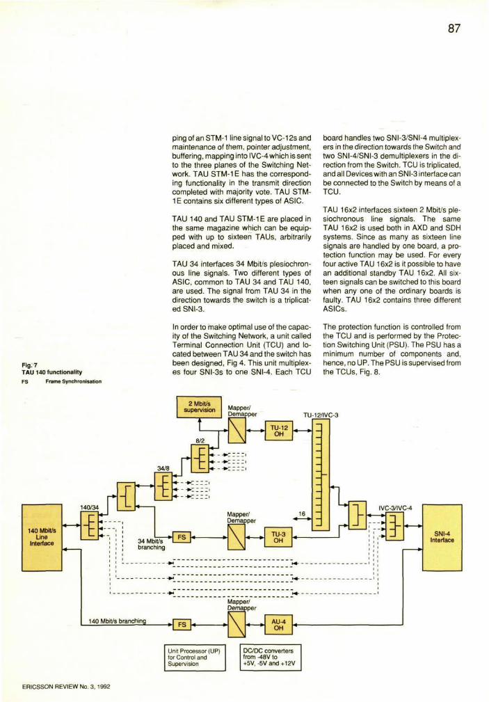
87
ping of an STM-1 line signal to VC-12s and maintenance of them, pointer adjustment, buffering, mapping into IVC-4 which is sent to the three planes of the Switching Network. TAU STM-1 E has the corresponding functionality in the transmit direction completed with majority vote. TAU STM-1E contains six different types of ASIC.
TAU 140 and TAU STM-1 E are placed in the same magazine which can be equipped with up to sixteen TAUs, arbitrarily placed and mixed.
TAU 34 interfaces 34 Mbit/s plesiochron-ous line signals. Two different types of ASIC, common to TAU 34 and TAU 140, are used. The signal from TAU 34 in the direction towards the switch is a triplicated SNI-3.
board handles two SNI-3/SNI-4 multiplexers in the direction towards the Switch and two SNI-4/SNI-3 demultiplexers in the direction from the Switch. TCU is triplicated, and all Devices with an SNI-3 interface can be connected to the Switch by means of a TCU.
TAU 16x2 interfaces sixteen 2 Mbit/s ple-siochronous line signals. The same TAU 16x2 is used both in AXD and SDH systems. Since as many as sixteen line signals are handled by one board, a protection function may be used. For every four active TAU 16x2 is it possible to have an additional standby TAU 16x2. All sixteen signals can be switched to this board when any one of the ordinary boards is faulty. TAU 16x2 contains three different ASICs.
Fig. 7 TAU 140 functionality
FS Frame Synchronisation
I n order to make optimal use of the capacity of the Switching Network, a unit called Terminal Connection Unit (TCU) and located between TAU 34 and the switch has been designed, Fig 4. This unit multiplexes four SNI-3s to one SNI-4. Each TCU
The protection function is controlled from the TCU and is performed by the Protection Switching Unit (PSU). The PSU has a minimum number of components and, hence, no UP. The PSU is supervised from theTCUs, Fig. 8.
ERICSSON REVIEW No. 3, 1992
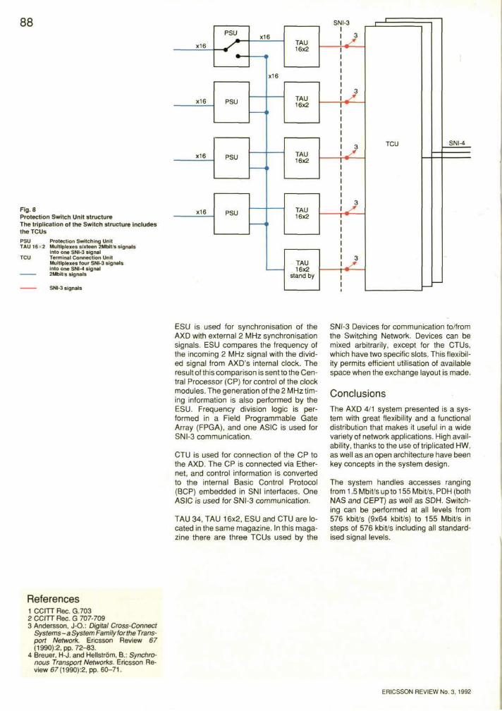
ESU is used for synchronisation of the AXD with external 2 MHz synchronisation signals. ESU compares the frequency of the incoming 2 MHz signal with the divided signal from AXD's internal clock. The result of this comparison is sent to the Central Processor (CP) for control of the clock modules. The generation of the 2 MHz timing information is also performed by the ESU. Frequency division logic is performed in a Field Programmable Gate Array (FPGA), and one ASIC is used for SNI-3 communication.
CTU is used for connection of the CP to the AXD. The CP is connected via Ethernet, and control information is converted to the internal Basic Control Protocol (BCP) embedded in SNI interfaces. One ASIC is used for SNI-3 communication.
TAU 34, TAU 16x2, ESU and CTU are located in the same magazine. In this magazine there are three TCUs used by the
SNI-3 Devices for communication to/from the Switching Network. Devices can be mixed arbitrarily, except for the CTUs, which have two specific slots. This flexibility permits efficient utilisation of available space when the exchange layout is made.
Conclusions The AXD 4/1 system presented is a system with great flexibility and a functional distribution that makes it useful in a wide variety of network applications. High availability, thanks to the use of triplicated HW, as well as an open architecture have been key concepts in the system design.
The system handles accesses ranging from 1.5 Mbit/s up to 155 Mbit/s, PDH (both NAS and CEPT) as well as SDH. Switching can be performed at all levels from 576 kbit/s (9x64 kbit/s) to 155 Mbit/s in steps of 576 kbit/s including all standardised signal levels.
References 1 CCITT Rec. G.703 2 CCITT Rec. G 707-709 3 Andersson, JO.: Digital Cross-Connect
Systems - a System Family for the Transport Network. Ericsson Review 67 (1990):2, pp. 72-83.
4 Breuer, H-J. and Hellstrom, B.: Synchronous Transport Networks. Ericsson Review 67(1990):2, pp. 60-71.
ERICSSON REVIEW No. 3. 1992
Fig. 8 Protection Switch Unit structure The triplication of the Switch structure includes the TCUs
88

ERICSSON
ISSN 0014-0171 Telefonaktiebolaget LM Ericsson 92434 Ljungforetagefl. Orebro 1992