Ericsson Axe Platform
27
Ericsson AXE PLATFORM
-
Upload
tongaimutengwa5194 -
Category
Documents
-
view
250 -
download
12
description
AXE
Transcript of Ericsson Axe Platform

Ericsson AXE PLATFORM

Digital switching
The two principles of digital switching are:
• Time switching• Space switching

• Time switching is based on time division multiplexing (TDM) systems for example pulse code modulation (PCM).• A PCM link can be shared in time by a number of speech channels. • Each channel's share of this time is known as a time slot, and each
time slot carries a speech sample.• Speech samples from subscribers are transmitted in a fixed order and
are received in the same order. • This allows speech connections to be set up between subscribers

A simple time switch is made up of:• A speech store for temporary storage of the speech samples• A control store which controls the reading out from the speech store• The time switch module (TSM) function block is implemented in
hardware and regional and central software• The hardware units in TSM are digital link multiplexer (DLMUX), time
switch module (TSM) and space switch module (SPM).

The TSM function block performs the following functions • Traffic functions within and towards the hardware• Controls the traffic queues and timeslots in the switch• Functions for supervision of TSM, SPM, SNT and digital path (DIP)• Functions for test of TSM and SPM hardware• Administrative functions for TSM and SPM

• The TSM, the DLMUX and the SPM are duplicated in two planes, plane A and plane B.• The DLMUX was introduced in BYB501 and its goal is to put together
several 2 Mbit/s PCM connections to the group switch.• In BYB 202 the 2 Mbit/s PCM connections are directly connected to
the Group switch and more specific to TSM

• Space switching is used to switch timeslots from an incoming PCM system to an outgoing PCM system.• The space switch is composed of a matrix of cross points (electronic
gates). • To connect a timeslot in an incoming PCM system to a timeslot in an
outgoing PCM system an appropriate cross point of the space switch is operated for a defined period (an internal timeslot).

GS INTRODUCTION
• In all AXE systems that connect two or more subscribers to one another, the Group Switch is the dominant feature, and is generally seen as the core around which the system is built.
The Group Switching Subsystem, GSS, has the following basic functions:• Selection, connection and disconnection of speech or signal paths
passing through the Group Switch.• Supervision of hardware in the subsystem by continuous, periodic and
traffic-dependent supervision, for example through-connection tests.

• Supervision of DL, Digital Link, interfaces connected to the switch.• To maintain a stable and accurate clock frequency for network
synchronization purposes.

Configuration of the group switch• The group switch can be configured for different capacities.• Each time switch module can connect 16 PCM links carrying 512 timeslots.• One space switch module can handle 32 time switch modules.• That is the structure of a 16 K group switch with a capacity of 16 384 multiple
positions (MUPs). 1 K is equal to 1024.• The multiple positions (MUP) are data areas for storage of the speech
samples in the speech stores. • One unique multipleposition is needed for each subscriber in each call.• A 16 K group switch, complete with regional processors, fits in a• single subrack for each plane.


The possible configurations of the AXE group switch are regarding the capacity of multiple positions• 16 K (16 384 MUPs)• 32 K (32 768 MUPs)• 48 K (49 152 MUPs)• 64 K (65 536 MUPs)• 128 K (131 072 MUPs)
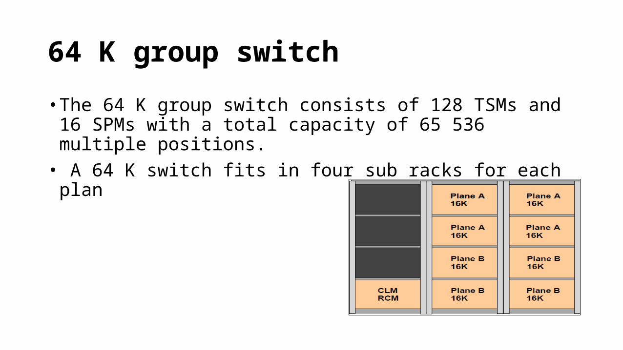
64 K group switch
• The 64 K group switch consists of 128 TSMs and 16 SPMs with a total capacity of 65 536 multiple positions.• A 64 K switch fits in four sub racks for each plan

GEM - Generic Ericsson Magazine Concept
• GEM in its basic configuration contains two duplicated 16 kMUPs Group switch units per magazine plus a pair of regional maintenance processors. • The GEM provides physical space for up to 22 different devices such
as: TRA R7, ET155-1, SCB-RP, XDB, DLEB, CGB, IRB, LRB and CDB. • The RP Bus and a 100 Mbit/s Ethernet are connected to each physical
slot of the GEM magazine.

• When switch sizes larger than 16 kMUPs are required, or when the number of devices exceeds 22, additional GEM(s) must be added. The configuration of additional GEM(s) may be made while the system is processing traffic (no traffic disturbances will be caused as a result of this action).
• GEMs are connected in columns and rows by Highway Vertical (HWV) and Highway Horizontal (HWH) interfaces. Both HWV and HWH are cable interfaces carrying 8192 payload timeslots and 128 overhead timeslots.
• GEM supports DL5 internal switch interface which is intended for connection of a high order DLMUX, MUX5 or MUXSP to the switch core. Also DL-34 interface is supported. It is optimized for communication between the GS890 and the various high-speed devices. DL3 interfaces can be handled using the DLEB boards.
• GEM NNRP5 is a special type of GEM magazines where the magazine simply acts as device magazine for GEM devices. The Group Switch capacity is limited by the Group Switch in the AXE10 BYB501 node to which the GEM NNRP5 magazine is connected.

Devices Adapted to GEM Type Concept TRA R6 (CSPB 1.0)• TRA R6 is a CSPB 1.0 based application. • It supports all codecs used in GSM system, i.e. EFR, FR, HR and Adaptive MultiRate codec
(AMR) HR & FR. • It also supports TFO for EFR, AMR-FR and AMR-HR. • The TRA R6 is built in a DSP ASIC technology developed especially for speech processing.• This results in the ability to handle 192 speech channels per board, small size and low
power consumption. • When TFO is used the channel density is reduced to 128 channels per board for
narrowband codecs. • It is connected to the Group Switch via a DL34 interface and is controlled by the APZ via
an on-board regional processor (RPI).

• ET155-1 STM-1• ET155-1 STM-1 is a 155 Mbit/s STM-1 Exchange Terminal that can terminate up to
sixty three 2 Mbit/s PDH tributaries. • It supports ETSI standards. The ET155-1 STM-1 is a single board implementation (two
boards if protection is required) that is mounted in the GEM magazine.• A maximum of 8 fully utilized ET155-1 and 8 standby (protection) ET155-1 can fit into
a GEM magazine when using fully equipped STM-1 frames. • For non-fully utilized STM-1 frames, a maximum of 22 ET-155-1 can be placed into the
GEM magazine. • In any case, the limitation is 16k ports and 22 board positions. • The ET155-1 is connected to the Group Switch via a DL34 interface and is controlled
by the APZ via an on-board regional processor (RPI).

• Digital Link MUX for Existing Equipment Board - DLEB• DLEB is a DLMUX that demultiplexes DL34 to DL3. • One DLEB can handle four DL3 cables from GDM magazines and one DL3 cable
from ET155-7 for LOT protection.• (The DL3 cable for LOT protection is not used under normal conditions. • It is connected to the same TS4B used by the other four DL3. • If a fault occurs this DL3 is electrical inserted by a three-state connector. • No manual intervention is needed.) • There is one DLEB for each plane. • The two DLEBs for plane A and B are placed in the slots 11 positions apart.

• Clock Generation Board - CGB• CGB generates Clock and Synchronization signal to the switch.• Two CGBs are housed in the same GEM, in case of one GEM
configuration (16 kMUPs). • If the switch size is bigger than 16 kMUPs the CGBs are housed in
different GEMs in order to improve the reliability of the system.

Clock Distribution Board - CDB• The CDB distributes clock and synchronization to the switch. It is
necessary if the switch is bigger than 16 kMUPs. Incoming Reference Board - IRB• The IRB receives three external synchronization references that are
terminated, converted and distributed to the CGBs. Local Reference Board - LRB• The LRB delivers a high quality clock signal to the CGBs.

• Maintenance Processor Board - SCB-RP• This board takes in, filters and supervises the -48V. • It also supervises the Maintenance Bus and takes in the control bus from
CP (RPB-S). • It has an Ethernet switch on it, with a 100 Mbit/s and a 1 Gbit/s Ethernet
interface to the front and a 10/100/1000 Mbit/s interface to each board in the magazine. • It is always part of the GEM. Distributed Switch Board - XDB• XDB is 16 kMUPs switch board with switching and DLMUX functions.

MUX DL3-DL34 Board - M334B• The M334B board is only NNRP5 specific hardware. • The board is part of the GEM NNRP5 magazine. • It performs the DL3 to DL34 multiplexing giving the possibility to connect the
GEM-based devices to AXE10 BYB501 nodes. GESB Gigabit Ethernet Switch Board• GESB is a Gigabit Ethernet switch, able to handle inter communication between
GEM magazines as well as communication to GEM-external stations. • GESB provides eight 1000Base-TX ports towards the front. • All Ethernet ports support auto-negotiation and the switch support operation in
unmanaged mode.

PGWB Packet Gateway Board• PGWB is an Inter-Working Unit between the IP Ethernet interfaces
and the GSS.• Two 100Base-TX Ethernet ports are provided to the backplane. • The DL34 interface is provided to the backplane. • DL34 is the interface between PGWB and XDB.• The PGWB is used as a platform for the PGW application.

GARP-1• The Generic Application Resource Processor (GARP-1) is based on Power PC hardware platform.• GARP-1 is used for Signalling Transport (SIGTRAN) application, which secures stable operation and a
secure transition from traditional SS7 to SS7 over IP. • The GARP-1 board, handling the SIGTRAN application, is connected to the CP via the RP bus (RPB-S). • When used in the BSC, data packets are transferred to other signalling nodes using the current IP
infrastructure. • The GARP-1 boards are connected using the front ports to the BSC LAN switch and from there to
the Site Router and further towards the MSC and SMPC.• GARP-1 is also used for the Signalling GAN Handler SGH application.• The SGH application is used for the control signalling over the Up interface. • The SGH application uses GARP-1 backplane connectors for communication over Ethernet and
requires a magazine that includes an Ethernet Switch.

GARP-2• The Generic Application Resource Processor ver. 2 (GARP-2) is
equipped with a MPC 8548E processor and 2GB of DDR SDRAM. • GARP-2 has two Gigabit Ethernet interfaces in the backplane and two
on the front.• There is one GARP-2 HW version used for the TRH application and
another GARP-2 version used for the GPH application. • GARP-2 is the successor of RPG3 for the TRH application and RPP for
the GPH application.

• STEB• The STEB implements signalling terminal (ST) functionalities of No. 7
signalling using Nb and HSL protocol in AXE 810 system. • With reference to AXE architecture, STEB is equipped with a Regional
Processor (RP). • The protocol layers implemented on STEB are MTP1 and MTP2 for Nb
and HSL Q.703 Annex A or SAAL for HSL (ATM based). • STEB supports up to: 4 HSL links or 128 Nb signalling links.