ERGONOMIC CONTAINER LASHING · Container lashing is a strenuous, high risk, and dangerous activity....
30
Guide for Ergonomic Container Lashing GUIDE FOR ERGONOMIC CONTAINER LASHING JUNE 2017 American Bureau of Shipping Incorporated by Act of Legislature of the State of New York 1862 2017 American Bureau of Shipping. All rights reserved. ABS Plaza 16855 Northchase Drive Houston, TX 77060 USA
Transcript of ERGONOMIC CONTAINER LASHING · Container lashing is a strenuous, high risk, and dangerous activity....
G u i d e f o r E r g o n o m i c C o n t a i n e r L a s h i n g
GUIDE FOR
ERGONOMIC CONTAINER LASHING
JUNE 2017
American Bureau of Shipping Incorporated by Act of Legislature of the State of New York 1862
2017 American Bureau of Shipping. All rights reserved. ABS Plaza 16855 Northchase Drive Houston, TX 77060 USA

F o r e w o r d
Foreword ABS has produced this Guide for Ergonomic Container Lashing to provide a single source for ergonomic criteria related to container lashing and unlashing operations.
Injuries, and sometimes fatalities, related to the lashing and unlashing of containers represent a significant amount of the incidents that occur onboard container carriers. Container lashing and unlashing is also the cause of many crew member and dockworker near misses (close calls). During the design and construction of container carriers the provision of safe work areas for lashing/unlashing personnel is essential.
The purpose of this Guide and the associated notations are to benefit Owners by facilitating a safer, more ergonomic, working environment. This Guide focuses on the design aspect of lashing access and working location layout and outfitting. It contains requirements addressing the design aspects of IMO circular MSC.1/Circ.1352 (CSS Code Annex 14).
The Guide offers two (2) optional notations as follows:
• ERGO(LASH)-R (Ergonomic Lashing – Restricted)
• ERGO(LASH) (Ergonomic Lashing)
The ERGO(LASH)-R notation is applicable to existing container carriers, prescribing requirements based on good ergonomic practice, relating to container lashing. It is awarded for compliance with the relevant requirements contained in Section 2 of this Guide. It is considered that it will be more practicable to apply this notation’s requirements to existing container carriers with the understanding that existing ships are not required to be enlarged or undergo other major structural modifications.
The ERGO(LASH) notation is applicable to both existing and new container carriers prescribing enhanced ergonomic requirements based on the design guidelines contained in section 6 (Design) and section 8 (Specialized Container Safety Design), except subsection 6.3 (Lashing Systems), of Annex 14 of the Code of Safe Practice for Cargo Stowage and Securing (CSS Code) as adopted by MSC.1/Circ.1352. It is awarded for compliance with the relevant requirements contained in Section 2 of this Guide.
Research conducted by ABS as part of the ABS Mariner Safety Research Initiative (MSRI) has shown that leading causes of incidents (injuries and near misses) includes among other things, slips/trips and falls, dropped objects, and incomplete or incorrect lashing/unlashing. To respond to these issues, ABS has used the MSRI data repository to investigate and identify opportunities to improve working conditions for the lashing/unlashing activities on deck by addressing the above areas of concern. The different ergonomic notations can help reduce incidents (injuries and near misses), and improve worker safety and performance.
This Guide becomes effective on the first day of the month of publication.
Users are advised to check periodically on the ABS website www.eagle.org to verify that this version of this Guide is the most current.
We welcome your feedback. Comments or suggestions can be sent electronically by email to [email protected].
ii ABS GUIDE FOR ERGONOMIC CONTAINER LASHING . 2017

T a b l e o f C o n t e n t s
GUIDE FOR
ERGONOMIC CONTAINER LASHING CONTENTS SECTION 1 General .................................................................................................... 5
1 Introduction ......................................................................................... 5 2 Application and Scope ........................................................................ 6 3 Terminology ........................................................................................ 6 4 Notations ............................................................................................. 7
4.1 ERGO(LASH)-R Notation ................................................................ 7 4.2 ERGO(LASH) Notation ................................................................... 7
5 Documentation .................................................................................... 8 5.1 Risk Assessment ............................................................................. 8 5.2 Design Requirements ...................................................................... 8 5.3 Results ............................................................................................ 8
6 Process for Obtaining a Notation ........................................................ 8 7 Alternatives ......................................................................................... 9
7.1 General............................................................................................ 9 7.2 Other Regulations ........................................................................... 9 7.3 Departures from Criteria .................................................................. 9
SECTION 2 Requirements for Notation .................................................................. 10
1 Introduction ....................................................................................... 10 2 Risk Assessment Requirements ....................................................... 10
2.1 List the Job Steps .......................................................................... 10 2.2 Identify Hazards Associated with Each Job Step .......................... 11 2.3 Identify Existing Control Measures for Each Hazard ..................... 11 2.4 Performing Risk Analysis and Risk Evaluation .............................. 12
3 Design Requirements ....................................................................... 13 3.1 General Provisions ........................................................................ 13 3.2 Lashing Position Design (Platforms, Bridges and other Lashing
Positions) ....................................................................................... 13 3.3 Fencing Design ............................................................................. 18 3.4 Ladder and Manhole Design ......................................................... 19 3.5 Lashing Equipment Design ............................................................ 24 3.6 Lighting Design .............................................................................. 24 3.7 Specialized (Reefer) Container Safety Design .............................. 26
ABS GUIDE FOR ERGONOMIC CONTAINER LASHING . 2017 iii

TABLE 1 General Provisions .................................................................. 13 TABLE 2 Lashing Position Design ......................................................... 13 TABLE 3 Fencing Design ....................................................................... 18 TABLE 4 Ladder and Manhole Design ................................................... 20 TABLE 5 Lashing Equipment Design ..................................................... 24 TABLE 6 Reefer Container Safety Design ............................................. 26 FIGURE 1 Sample Risk Matrix with Risk Tolerability Criteria .................. 12 FIGURE 2 Work Area Between Container Stacks.................................... 14 FIGURE 3 Lashing Bridge ........................................................................ 15 FIGURE 4 Lashing Platforms on Outboard Stanchions ........................... 16 FIGURE 5 Work Area Between Hatch Covers ......................................... 17 FIGURE 6 Fencing Dimensions ................................................................ 19 FIGURE 7 Ladder Dimensions ................................................................. 21 FIGURE 8 Ladder Access from the Outside of the Lashing Platform ...... 22 FIGURE 9 Ladder Access through the Lashing Platform ......................... 22 FIGURE 10 Lashing Platform Manhole Dimensions .................................. 23 FIGURE 11 Vertical Ladder Guard Hoops (Ladder Length ≥ 3 m
(10 ft)) ...................................................................................... 23 SECTION 3 Survey Requirements ........................................................................... 27
1 General ............................................................................................. 27 2 Initial Survey During Construction (ERGO(LASH)) .......................... 27 3 Surveys After Construction (ERGO(LASH)-R and
ERGO(LASH)) .................................................................................. 27 3.1 Initial Survey for Existing Vessels Obtaining the ERGO(LASH)-R
Notation ......................................................................................... 27 3.2 Initial Survey for Existing Vessels Obtaining the ERGO(LASH)
Notation ......................................................................................... 27 3.3 Annual Surveys ............................................................................. 27 3.4 Special Periodical Surveys (ERGO(LASH)) .................................. 28 3.5 Requirements for Vessel Alterations .............................................. 28
APPENDIX 1 References ............................................................................................ 29 APPENDIX 2 Risk Assessment Form Template ....................................................... 30
iv ABS GUIDE FOR ERGONOMIC CONTAINER LASHING . 2017
S e c t i o n 1 : G e n e r a l
S E C T I O N 1 General
1 Introduction Ergonomics is defined as “the scientific discipline concerned with the understanding of interactions among humans and other elements of a system, and the profession that applies theory, principles, data, and methods to design in order to optimize human well-being and overall system performance” (International Ergonomics Association, 2011).
Injuries (and sometimes fatalities) related to the lashing and unlashing of containers represent a significant amount of the incidents that occur onboard container carriers in port. These incidents occur to both permanent crew members and also to dockyard workers engaged in the container securing operations. Container lashing and unlashing has also been the cause of many crew member and dockworker near misses (close calls).
Container lashing is a strenuous, high risk, and dangerous activity. During lashing and unlashing activities, containers are secured to the ship by means of lashing rods, turnbuckles, twist-locks, and other lashing equipment. Lashing equipment limits container movement, and prevents containers from falling overboard.
During the design and construction of container carriers, the provision of safe work areas for lashing/unlashing personnel is important. Container carrier owners and designers are reminded of the dangers associated with container lashing and unlashing operations and are encouraged to develop and use container securing systems which are safe by design. The aim is to eliminate or at least minimize:
• Container top work
• Work in other hazardous locations; and
• The use of heavy and difficult to handle securing equipment.
The provision of safe working conditions for container lashing and unlashing operations requires a focus on vessel design, operation, and maintenance. Additionally, potential safety issues on large container carriers are not necessarily the same as on smaller ones.
As per SOLAS Reg. VI/5.6, all ships engaged in carrying cargoes other than solids and liquid bulk cargoes are to carry a Cargo Securing Manual (CSM). The CSM is to be approved by the Administration or a recognized organization acting on their behalf.
The IMO Guidelines for the preparation of the CSM (MSC.1/Circ. 1353) requires that ships which are specifically designed and fitted for the purpose of carrying containers to have an approved Cargo Safe Access Plan (CSAP) onboard. The CSAP demonstrates that personnel will have safe access for container securing operations. It is important for this plan to detail vessel arrangements necessary for conducting cargo stowage and securing operations in a safe manner. Guidelines for specific requirements are contained in the Code of Safe Practice for Cargo Stowage and Securing (CSS Code) Annex 14, “Guidance on Providing Safe Working Conditions for Securing of Containers on Deck, as adopted by MSC.1/Circ.1352.
In support of Annex 14 of the CSS Code, ABS has prepared this Guide with the intent of providing additional information regarding the safe working condition for securing of containers on deck, as well as the criteria for the ERGO(LASH)-R and ERGO(LASH) notations.
Annex 14 of the CSS Code addresses, in addition to design, operational and maintenance procedures which are not addressed in the Guide but are encouraged to be considered in order to improve safety and to satisfy the requirements of the Administration (when applicable).
ABS GUIDE FOR ERGONOMIC CONTAINER LASHING . 2017 5

Section 1 General
2 Application and Scope This Guide is applicable to existing and new container carriers for which the optional ERGO(LASH)-R or ERGO(LASH) notation has been requested.
The purpose of the ABS Guide and the associated notations is to provide the marine container transportation industry with guidance on the design of a more ergonomic working environment.
A review of injuries reported to the ABS Mariner Safety Research Initiative (MSRI) was conducted to evaluate the severity and reported cause of injuries sustained during container securing operations. The ABS MSRI data was also reviewed to analyze the container carrier near misses. The key near misses align well with the reported injuries. They include, but are not limited to:
i) Leaving lashing gear hanging unsecured from containers and structure (struck by)
ii) Loss of vigilance/situational awareness (slip/trip/fall)
iii) Not following the proper processes or procedures (incomplete or incorrect lashing/unlashing)
To respond to these issues, ABS used the MSRI data to investigate and identify opportunities to improve the designs and layouts relating to the securing of containers on deck. The different ergonomic notations focus on improving safe working conditions for lashing and unlashing activities by addressing the key focus areas noted above. The different ergonomic notations can help reduce incidents (injuries and near misses), and improve worker safety and performance.
3 Terminology Administration (Flag State): The Government of the State whose flag the ship is entitled to fly.
Cargo Safe Access Plan (CSAP): Ships which are specifically designed and fitted for the purpose of carrying containers are to be provided with a Cargo Safe Access Plan (CSAP) in order to demonstrate that personnel will have safe access for container securing operations. This plan is to detail arrangements necessary for the conducting of cargo stowage and securing in a safe manner. It is to include the following for all areas to be worked by personnel (refer also to MSC.1/Circ.1353/Rev.1):
• Hand rails
• Platforms
• Walkways
• Ladders
• Access covers
• Location of equipment storage facilities
• Lighting fixtures
• Container alignment on hatch covers/pedestals
• Fittings for specialized containers, such as reefer plugs/receptacles
• First aid stations and emergency access/egress
• Gangways
• Any other arrangements necessary for the provision of safe access
Container Carrier: For application of this Guide, a container carrier is a vessel designed primarily for the carriage of containers on deck and those parts of other ships for which arrangements are specifically designed and fitted for the purpose of carrying containers on deck.
Fencing: A generic term for guardrails, safety rails, safety barriers and similar structures that provide protection against the falls of persons.
6 ABS GUIDE FOR ERGONOMIC CONTAINER LASHING . 2017

Section 1 General
Fully Automatic Twistlock (FAT): A twistlock that is inserted and secured in the four bottom corner fittings on the quay before the container is stowed on top of another container onboard the vessel. The geometry of the twistlock design engages the corner fittings of the lower container and does not require stevedores to lock or unlock the fitting when stowing or discharging containers.
High-Cube Container: A container similar in structure to ISO standard containers, but taller. While a standard container has a maximum height of 2591 mm (8'-6"), a high-cube container is 2896 mm (9'-6") tall.
Illuminance: The luminous flux density at a surface (or the amount of light falling on an object or surface), i.e., the luminous flux incident-per-unit area. Illuminance is measured in units of Lux (lm/m2) or foot-candles (fc; lm/ft2). One foot-candle equals 10.76 Lux.
Lashing Positions: Refers to the following positions:
• In between container stows on hatch covers
• At the end of hatches
• On outboard lashing stanchions/pedestals
• Outboard lashing positions on hatch covers
• Any other position where people work with container securing
Lashing Rod: A tension element (typically made of steel) that has the appropriate strength and length that forms the lashing assembly used in conjunction with a tensioning device and lashing points. One end is fitted in a container corner casting and the other end is mated with the tensioning device.
Semi-Automatic Twistlock (SAT): A twistlock that is inserted and secured in the four bottom corner fittings on the quay before the container is stowed on top of another container on board the vessel. When the container is landed on top of another container, a spring mechanism in the twistlock automatically engages and secures the container above to the container below. This type of twistlock must be manually released or unlocked to discharge the container above.
Securing: Refers to container lashing and unlashing operations.
Stringers: The upright or sides of a ladder.
Tensioning Device: An adjustable device used to tighten a lashing (i.e., turnbuckle).
Turnbuckles: A specific type of Tensioning Device.
4 Notations This Guide offers two (2) optional notations related to ergonomic container lashing, ERGO(LASH)-R and ERGO(LASH).
4.1 ERGO(LASH)-R Notation The ERGO(LASH)-R notation is applicable to existing container carriers, prescribing requirements based on good ergonomic practice, relating to container lashing. It is awarded for compliance with the relevant requirements contained in Section 2 of this Guide. It is considered that it will be more practicable to apply this notation’s requirements to existing container carriers with the understanding that existing ships are not required to be enlarged or undergo other major structural modifications.
4.2 ERGO(LASH) Notation The ERGO(LASH) notation is applicable to both existing and new container carriers prescribing enhanced ergonomic requirements based on the design guidelines contained in section 6 (Design) and section 8 (Specialized Container Safety Design), except subsection 6.3 (Lashing Systems), of Annex 14 of the Code of Safe Practice for Cargo Stowage and Securing (CSS Code) as adopted by MSC.1/Circ.1352. It is awarded for compliance with the relevant requirements contained in Section 2 of this Guide.
ABS GUIDE FOR ERGONOMIC CONTAINER LASHING . 2017 7

Section 1 General
5 Documentation Relevant plans and documentation are to be submitted for approval and review as follows. Plans are to generally be submitted electronically to ABS. However, hard copies will also be accepted.
5.1 Risk Assessment For existing vessels requesting either the ERGO(LASH)-R or the ERGO(LASH) notation a risk assessment is not required to be carried out.
For new vessels requesting the ERGO(LASH) notation, a risk assessment is to be performed at the design stage as described in Subsection 2/2 of this Guide in order to comfirm that securing operations can be safely carried out in all anticipated container configurations. This assessment is to be conducted with a view toward developing the Cargo Safe Access Plan (CSAP).
The risk assessment is to be prepared and submitted to ABS for review.
5.2 Design Requirements 5.2.1 For Vessels Requesting the ERGO(LASH)-R Notation
For vessels requesting the ERGO(LASH)-R notation, the following plans, reflecting the current configuration and covering all the relevant requirements, are to be prepared and submitted to ABS Engineering for approval in advance of ABS Surveyor verification.
i) Arrangement and outfitting drawings
ii) Reefer container electric power supply system drawings
5.2.2 For Vessels Requesting the ERGO(LASH) Notation For vessels requesting the ERGO(LASH) notation, the following plans covering all the relevant requirements are to be prepared and submitted to ABS Engineering for approval:
i) Cargo Safe Access Plan (Note: for existing vessels, alternatively, the arrangement and outfitting drawings)
ii) Lighting Plan (only applicable to new vessels)
iii) Reefer container electric power supply system drawings
5.3 Results ABS Engineering will review and approve the submitted documentation. ABS Engineering is to report any deviation from the criteria to the Owner/shipyard for resolution and is to also identify any criteria that the ABS Surveyors is to field-verify.
The ABS Surveyor is to verify that the arrangements are in accordance with the approved documentation. The ABS Surveyor also is to verify resolution of outstanding comments noted from the ABS Engineering review and document deviations from criteria.
6 Process for Obtaining a Notation At the request of the Owner, operator, or builder, a container carrier complying with the minimum criteria for ergonomic lashing provided in this Guide may be assigned the ERGO(LASH)-R or ERGO(LASH) notation, as applicable.
The process is divided into three (3) stages as follows:
1. Risk Assessment. A risk assessment (when applicable) is to be conducted, as prescribed in Subsection 2/2 of this Guide.
2. Design Approval. All required documents, as listed in Subsection 1/5 of this Guide, are to be submitted to ABS Engineering for review (risk assessment report, when applicable) and approval (design related documentation).
8 ABS GUIDE FOR ERGONOMIC CONTAINER LASHING . 2017

Section 1 General
3. Survey Verification of Design. Follow-up physical verification of all prescribed ergonomic criteria is to be performed by an ABS Surveyor. For vessels requesting the ERGO(LASH) notation, lighting testing is to be performed as prescribed in 2/3.6 of this Guide
The ABS Engineering ergonomic assessment and ABS Surveyor verification and lighting testing (when applicable), are to be reviewed by the ABS Surveyor for notation confirmation.
7 Alternatives
7.1 General ABS will consider alternative arrangements and criteria, which can be shown to satisfy the criteria directly cited or referred to in this Guide. The demonstration of an alternative’s acceptability can be made through either the presentation of satisfactory service experience or systematic analysis based on valid engineering principles.
7.2 Other Regulations ABS will consider for acceptance alternative arrangements and details which can be shown to comply with standards recognized in the country in which the container carrier is registered (flag State) provided they are deemed not less effective.
7.3 Departures from Criteria It is recognized that unusual or unforeseen conditions may lead to a case where one or more of the parameters of interest in granting a notation may temporarily fall outside the range of acceptability.
When a departure from criteria is identified, during either the notation’s initial issuance or reconfirmation process, it is to be reviewed by ABS in consultation with the shipyard or the Owner. When the ergonomic design contains departures from the stated criteria, these will be subject to special consideration upon the receipt of details about the departure. Depending on the degree and consequences of the departure, the shipyard or Owner may be required to provide an assessment and remediation plan to obtain or maintain the notation. Failure to complete the agreed remediation by the due date will lead to withdrawal of the notation.
ABS GUIDE FOR ERGONOMIC CONTAINER LASHING . 2017 9

S e c t i o n 2 : R e q u i r e m e n t s f o r N o t a t i o n
S E C T I O N 2 Requirements for Notation
1 Introduction This Section describes the risk assessment and design related requirements for award of the notation. The requirements cover the design guidelines denoted in Annex 14 of the Code of Safe Practice for Cargo Stowage and Securing (CSS Code) as adopted by MSC.1/Circ.1352 (see Subsection 1/4 of this Guide). Additional ergonomic design principles relating to the lashing and unlashing of containers are also addressed.
2 Risk Assessment Requirements As stated in 1/5.1 of this Guide, a risk assessment (when applicable) is to be prepared and submitted to ABS for review.
For new vessels requesting the ERGO(LASH) notation, a risk assessment is to be performed at the design stage to review the hazards associated with performing container securing operations, in particular container lashing and unlashing. The objective of the study is to prevent harm to individual(s) carrying out the task by verifying the availability of safe access, appropriate securing equipment, safe places of work, and provision of adequate control measures to eliminate or mitigate any identified hazards. The risk assessment is to take into account the preliminary Cargo Safe Access Plan (CSAP), the anticipated container configurations, cargo securing equipment, the lashing plans contained within the Cargo Securing Manual; and all the persons that may be affected by the work activity.
It is recommended that the risk assessment is carried out by a team that includes the designer, owner/operator, and cargo securing equipment manufacturer(s). ABS’ participation in the risk assessment is also recommended. Appendix 2 of the ABS Guide for Risk Evaluations for the Classification of Marine-Related Facilities provides an overview of how to assemble an appropriate risk assessment team.
For existing vessels requesting either the ERGO(LASH)-R or the ERGO(LASH) notation, a risk assessment is not required to be carried out.
Risk assessment is an analytical process consisting of four steps:
1. Identifying the basic job steps in container lashing and unlashing
2. For each job step, reviewing associated potential safety and health hazards
3. Identifying existing control measures for each identified hazardous scenario
4. Performing risk analysis and risk evaluation
The following Paragraphs describe the requirements of the risk assessment process.
2.1 List the Job Steps Each step of the container lashing and unlashing operation is to be discretely identified and listed in the correct sequence. Each step is to be described in terms of what is to be done, where the work is carried out with respect to area/location, and who will carry out the task.
10 ABS GUIDE FOR ERGONOMIC CONTAINER LASHING . 2017

Section 2 Requirements for Notation
2.2 Identify Hazards Associated with Each Job Step Hazards for each job step need to be identified to determine if there are any potential risks which require control. Hazards related to container lashing and unlashing are to include but not be limited to:
i) Physical Hazards:
• Slips, trips and falls
• Falls from height
• Injuries while manually handling lashing gear
• Being struck by falling lashing gear or other objects
ii) Work Environments:
• Inadequate access to areas to safely perform container securing operations
• Potential damage due to container operations. High-risk areas are to be identified in order to develop appropriate protection or other methods of preventing significant damage
• Non-ergonomic design (e.g., size and weight of equipment) of lashing equipment
• Implications of lashing 9'6" high, or higher, containers and mixed stows of 40' and 45' containers
• Adjacent electrical risks (temperature controlled unit cable connections, etc.)
• Inadequate lighting (insufficient, poorly distributed) and glare
iii) External Weather Conditions:
• Heavy Winds
• Rain/Storm/Lighting
• Snow Storm/Ice
Appendix 2, Table 1 of the ABS Guidance Notes on Job Safety Analysis for the Marine and Offshore Industries provides a list of typical hazards for additional consideration.
2.3 Identify Existing Control Measures for Each Hazard Controls are methods, policies, actions, or equipment used to eliminate or reduce the hazard. The objective of this step is to identify existing adequate risk mitigation controls for each identified hazard. Existing controls refers to normal and available controls generally associated with the task by procedure, company policy, common practice, etc. There are four types of controls that can be implemented to reduce risks, listed in the preferred order of implementation:
• Elimination or Substitution. The elimination of the task, or the hazard associated with the task is to always be the first consideration. Careful evaluation may indicate that the task is not necessary or can be performed in a different way.
• Engineering. Engineering controls are mechanical or physical features incorporated to the equipment, systems, the job, or area around the job to remove or control the hazard, either by initial design specifications or by applying methods of substitution, minimization, isolation, or ventilation.
• Administrative. Administrative controls rely more actively on human action and behavior. Examples of administrative controls include written operating procedures, checklists, safety meetings, alarms, signs, training of personnel.
• Personal Protective Equipment. Personal protective equipment (PPE) creates a barrier between the person wearing the PPE and the hazard associated with the job. PPE such as ear muffs, protective clothing, safety glasses, respirators, gloves, welding aprons, and hardhats are methods of controlling hazards.
Appendix 2 of the ABS Guidance Notes on Job Safety Analysis for the Marine and Offshore Industries provides further guidance on typical hazards and possible controls that can be used to prevent or mitigate the hazard.
ABS GUIDE FOR ERGONOMIC CONTAINER LASHING . 2017 11

Section 2 Requirements for Notation
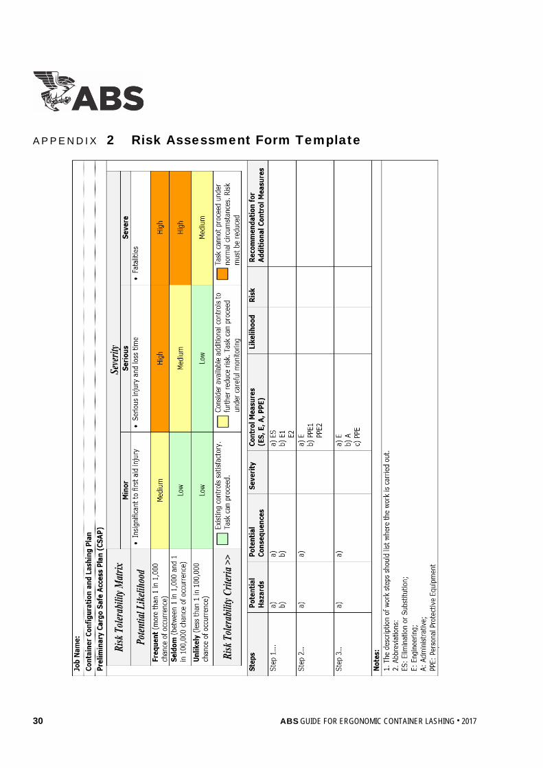
2.4 Performing Risk Analysis and Risk Evaluation Risk analysis for a given hazardous scenario involves the estimation of the likelihood and the severity resulting from its occurrence. Control measures and their effectiveness are also evaluated during the analysis. The level of risk (i.e., risk ranking) is to be evaluated based on the likelihood of occurrence and the severity of the consequence so that due attention is given to the high risk hazards. The risk evaluation is a qualitative estimation based on the experience of the risk assessment team and judgment. The owner/operator is to consider risk tolerance standards that are aligned with their health, safety, and environmental objectives. The risk tolerability can be embedded in a risk matrix developed by the owner/operator by setting the risk tolerance threshold value above which mitigation is mandatory. It is recognized that for existing vessels, risk control measures are not intended to require the vessel to be enlarged or undergo major structural modifications but rather to identify alternative measures so as to minimize the risk from hazardous scenarios during container securing operations as far as reasonably practicable.
In the sample matrix given in Section 2, Figure 1, there are three regions of risk: Low, Medium, and High. The actions of the workers are to be based on where the hazard falls in the matrix. The identification of additional risk controls is necessary for any risks that are not controlled to a tolerable level with existing controls. It is recommended that the residual risk is reassessed once additional risk reduction controls have been determined.
FIGURE 1 Sample Risk Matrix with Risk Tolerability Criteria
Consequence
Minor Serious Severe
Like
lihoo
d
Frequent Medium High High
Seldom Low Medium High
Unlikely Low Low Medium
Risk Risk Tolerability Criteria Low Existing controls satisfactory. Work can proceed.
Medium Consider available additional controls to further reduce the risk. Work can proceed once the additional controls, if any, are in place.
High Risk reduction controls are mandatory. Work cannot start until the risk has been reduced.
A sample risk assessment form is provided in Appendix 2 of this Guide. Further guidance on risk assessment techniques can be found in the ABS Guidance Notes on Risk Assessment Applications for the Marine and Offshore Oil and Gas Industries.
12 ABS GUIDE FOR ERGONOMIC CONTAINER LASHING . 2017
Section 2 Requirements for Notation
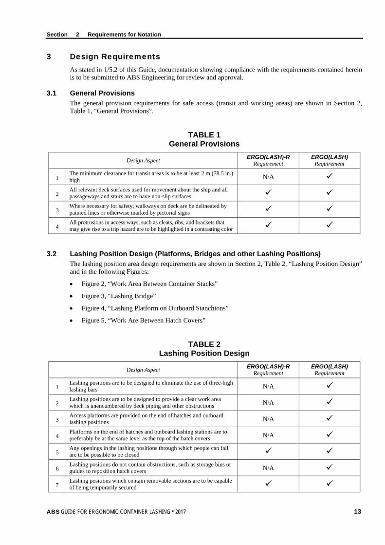
3 Design Requirements As stated in 1/5.2 of this Guide, documentation showing compliance with the requirements contained herein is to be submitted to ABS Engineering for review and approval.
3.1 General Provisions The general provision requirements for safe access (transit and working areas) are shown in Section 2, Table 1, “General Provisions”.
TABLE 1 General Provisions
Design Aspect ERGO(LASH)-R Requirement
ERGO(LASH) Requirement
1 The minimum clearance for transit areas is to be at least 2 m (78.5 in.) high N/A
2 All relevant deck surfaces used for movement about the ship and all passageways and stairs are to have non-slip surfaces
3 Where necessary for safety, walkways on deck are be delineated by painted lines or otherwise marked by pictorial signs
4 All protrusions in access ways, such as cleats, ribs, and brackets that may give rise to a trip hazard are to be highlighted in a contrasting color
3.2 Lashing Position Design (Platforms, Bridges and other Lashing Positions) The lashing position area design requirements are shown in Section 2, Table 2, “Lashing Position Design” and in the following Figures:
• Figure 2, “Work Area Between Container Stacks”
• Figure 3, “Lashing Bridge”
• Figure 4, “Lashing Platform on Outboard Stanchions”
• Figure 5, “Work Are Between Hatch Covers”
TABLE 2 Lashing Position Design
Design Aspect ERGO(LASH)-R Requirement
ERGO(LASH) Requirement
1 Lashing positions are to be designed to eliminate the use of three-high lashing bars N/A
2 Lashing positions are to be designed to provide a clear work area which is unencumbered by deck piping and other obstructions N/A
3 Access platforms are provided on the end of hatches and outboard lashing positions N/A
4 Platforms on the end of hatches and outboard lashing stations are to preferably be at the same level as the top of the hatch covers N/A
5 Any openings in the lashing positions through which people can fall are to be possible to be closed
6 Lashing positions do not contain obstructions, such as storage bins or guides to reposition hatch covers N/A
7 Lashing positions which contain removable sections are to be capable of being temporarily secured
ABS GUIDE FOR ERGONOMIC CONTAINER LASHING . 2017 13
Section 2 Requirements for Notation
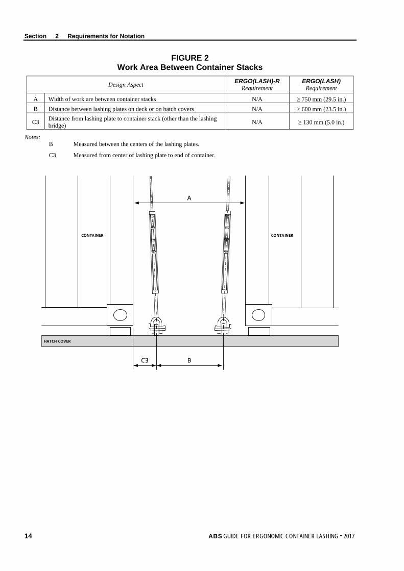
FIGURE 2 Work Area Between Container Stacks
Design Aspect ERGO(LASH)-R Requirement
ERGO(LASH) Requirement
A Width of work are between container stacks N/A ≥ 750 mm (29.5 in.) B Distance between lashing plates on deck or on hatch covers N/A ≥ 600 mm (23.5 in.)
C3 Distance from lashing plate to container stack (other than the lashing bridge) N/A ≥ 130 mm (5.0 in.)
Notes: B Measured between the centers of the lashing plates.
C3 Measured from center of lashing plate to end of container.
HATCH COVER
CONTAINER CONTAINER
A
BC3
14 ABS GUIDE FOR ERGONOMIC CONTAINER LASHING . 2017

Section 2 Requirements for Notation
FIGURE 3 Lashing Bridge
Design Aspect ERGO(LASH)-R Requirement
ERGO(LASH) Requirement
C1 Distance from lashing bridge fencing to container stack N/A ≤ 1100 mm (43.5 in.) C2 Distance from lashing plate to container stack (lashing bridge) N/A ≥ 220 mm (8.5 in.) F Width of lashing bridge between top rails of fencing ≥ 600 mm (23.5 in.) ≥ 750 mm (29.5 in.)
F1 Width of lashing bridge between storage racks, lashing cleats and any other obstruction ≥ 500 mm (19.5 in.) ≥ 600 mm (23.5 in.)
K Width of lashing bridge between top rails of fencing ≥ 600 mm (23.5 in.) ≥ 750 mm (29.5 in.) K1 Width of lashing bridge between the pillars of the lashing bridge ≥ 500 mm (19.5 in.) ≥ 600 mm (23.5 in.)
Notes: C1 Measured from inside of fencing.
C2 Measured from center of lashing plate to end of container.
F, K Measured to inside of fencing.
KK1
FC1
F
C1
F1
C2
A A’
SECTION A-A’
ABS GUIDE FOR ERGONOMIC CONTAINER LASHING . 2017 15

Section 2 Requirements for Notation
FIGURE 4 Lashing Platforms on Outboard Stanchions
Design Aspect ERGO(LASH)-R Requirement
ERGO(LASH) Requirement
D Horizontal unfenced gap in fall protection N/A ≤ 300 mm (12.0 in.) GL Width of working platform for outboard lashing – fore/aft N/A ≥ 750 mm (29.5 in.) GT Width of working platform for outboard lashing – transverse N/A ≥ 750 mm (29.5 in.) E Gap in access platform N/A ≤ 70 mm (2.75 in.)
Notes: GL Measured from end of container to inside of fencing.
GT Measured to inside of fencing.
GT
GLE
HATCH COVER
OUTBOARD LASHING
STANCHION PLATFORM TO ENABLE ACCESS TO THE STANCHION FROM THE
ADJACENT HATCH COVER
D
16 ABS GUIDE FOR ERGONOMIC CONTAINER LASHING . 2017

Section 2 Requirements for Notation
FIGURE 5 Work Area Between Hatch Covers
Design Aspect ERGO(LASH)-R Requirement
ERGO(LASH) Requirement
C3 Distance from lashing plate to container stack (elsewhere) N/A ≥ 130 mm (5.0 in.)
I Width of work platform at end of hatch cover or adjacent to superstructure N/A ≥ 750 mm (29.5 in.)
J Distance from edge of hatch cover to fencing N/A ≥ 600 mm (23.5 in.)
Notes: C3 Measured from center of lashing plate to end of container.
I Measured to inside of fencing.
J Measured to inside of fencing.
I
HATCH COVER
COAMING
J
C3
I
J
ABS GUIDE FOR ERGONOMIC CONTAINER LASHING . 2017 17

Section 2 Requirements for Notation
3.3 Fencing Design The fencing design requirements are shown in Section 2, Table 3, “Fencing Design” and in Section 2, Figure 6, “Fencing Dimensions”.
TABLE 3 Fencing Design
Design Aspect ERGO(LASH)-R Requirement
ERGO(LASH) Requirement
1 Lashing Bridges and platforms, where appropriate, are to be fenced
2 When openings in safety barriers are necessary to allow container crane movements, particularly with derricking cranes, removable fencing is to be used whenever possible.
3 The fencing is formed by a top handrails and two intermediate rails N/A
4 The fencing is formed by a top handrails and one intermediate rail N/A
5 Toe boards (or kick plates) are to be provided around the sides of elevated lashing bridges and platforms to prevent securing equipment from falling and injuring people.
6 Lashing provisions are provided for locking and removal of fencing as operational situations change based on stowage anticipated for that area
N/A
7 Fences and handrails are to be highlighted with a contrasting color different from the background
8 Athwartships cargo securing walkways are to be protected by adequate fencing if an unguarded edge exists when the hatch cover is removed
9
Rails and/or any temporary fittings are to be designed to prevent workers from falling. Fencing is to be designed to withstand anticipated loads not less than 90 kg (200 lbs) at any point and in any direction when applied to the top rail.
N/A
18 ABS GUIDE FOR ERGONOMIC CONTAINER LASHING . 2017

Section 2 Requirements for Notation
FIGURE 6 Fencing Dimensions
Design Aspect ERGO(LASH)-R Requirement
ERGO(LASH) Requirement
A Height of handrail (measured to the top of the handrail) ≥ 1000 mm (39.5 in.) ≥ 1000 mm (39.5 in.) B Opening between intermediate rails ≤ 500 mm (19.5 in.) ≤ 380 mm (15.0 in.) C Opening below the lowest rail N/A ≤ 230 mm (9.0 in.)
D Height of toeboard (General) Height of toeboard (When obstructs the stowage of containers)
≥ 100 mm (4.0 in.) ≥ 150 mm (6.0 in.) ≥ 100 mm (4.0 in.)
E Gap between toeboard and surface N/A ≤ 6 mm (0.25 in.) F Horizontal unfenced gap in fall protection N/A ≤ 300 mm (12.0 in.)
TOEBOARD
A
B
B
C
E
TOEBOARD
TOEBOARD
D
B
B
C
B
B
C
A
A
F
F
3.4 Ladder and Manhole Design The ladder and manhole design requirements are shown in Section 2, Table 4, “Ladder and Manhole Design” and in the following Figures:
• Figure 7, “Ladder Dimensions”
• Figure 8, “Ladder Access for the Outside of the Lashing Platform”
• Figure 9, “Ladder Access through the Lashing Platform”
• Figure 10, “Lashing Platform Manhole Dimensions”
• Figure 11, “Vertical Ladder Guard Hoops (Ladder Length ≥ 3 m (10 ft))”
ABS GUIDE FOR ERGONOMIC CONTAINER LASHING . 2017 19

Section 2 Requirements for Notation
TABLE 4 Ladder and Manhole Design
Design Aspect ERGO(LASH)-R Requirement
ERGO(LASH) Requirement
1 A fixed ladder is to not be sloped at an angle greater than 25° from the vertical. Where the slope of a ladder exceeds 15° from the vertical, the ladder is to be provided with suitable handrails.
N/A
2
Where a fixed ladder gives access to the outside of a lashing position, the stringers are to be connected at their extremities to the guardrails of the lashing position, irrespective of whether the ladder is sloping or vertical.
N/A
3
Where a fixed ladder gives access to a lashing position through an opening in the platform, the opening is to be protected with either a fixed grate with a lock back mechanism, which can be closed after access, or fencing.
N/A
4 The top rung of the ladder is to be level with the floor of the platform unless the rungs are fitted to the ends of the stringers. N/A
5 A fixed vertical ladder of a height exceeding 3 m (10 ft), and any fixed vertical ladder from which a person may fall into a hold, is to be fitted with guard hoops.
N/A
6 Access ladders, walkways, and work platforms are to be designed so that workers do not have to climb over piping or work in areas with permanent obstructions.
N/A
7 There are to be no unprotected openings in any part of the workplace. Access opening are to be protected with handrails or access covers that can be locked back during access.
8 Manholes are not to be situated in transit areas. However, if they are, proper fencing is to protect them.
9 Handholds are to be provided at the top of the ladder to enable safe access to the platform to be gained.
10 Manhole openings that may present a fall hazard are to be highlighted in contrasting color around the rim of the opening.
11 Manhole openings at different levels of the lashing bridge are not to be located directly below one another, as far as practicable. N/A
20 ABS GUIDE FOR ERGONOMIC CONTAINER LASHING . 2017
Section 2 Requirements for Notation
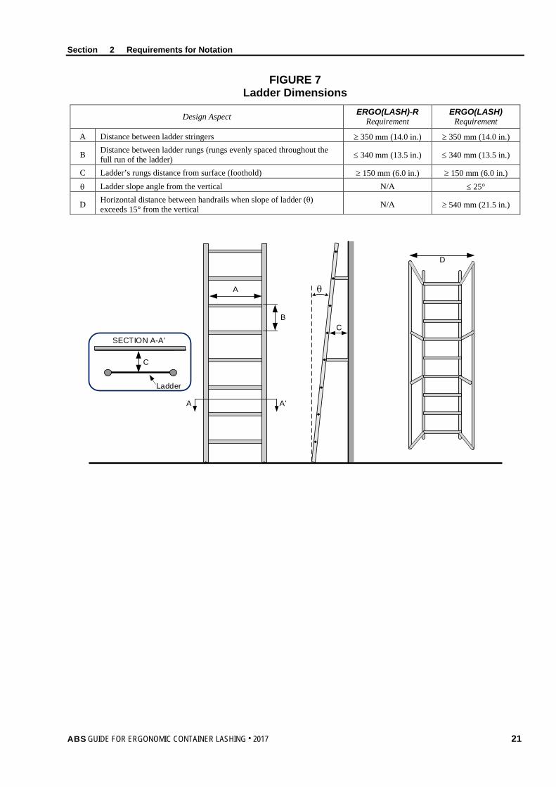
FIGURE 7 Ladder Dimensions
Design Aspect ERGO(LASH)-R Requirement
ERGO(LASH) Requirement
A Distance between ladder stringers ≥ 350 mm (14.0 in.) ≥ 350 mm (14.0 in.)
B Distance between ladder rungs (rungs evenly spaced throughout the full run of the ladder) ≤ 340 mm (13.5 in.) ≤ 340 mm (13.5 in.)
C Ladder’s rungs distance from surface (foothold) ≥ 150 mm (6.0 in.) ≥ 150 mm (6.0 in.) θ Ladder slope angle from the vertical N/A ≤ 25°
D Horizontal distance between handrails when slope of ladder (θ) exceeds 15° from the vertical N/A ≥ 540 mm (21.5 in.)
A
B
A A’
SECTION A-A’
Ladder
θ
C
C
D
ABS GUIDE FOR ERGONOMIC CONTAINER LASHING . 2017 21

Section 2 Requirements for Notation
FIGURE 8 Ladder Access from the Outside of the Lashing Platform
Design Aspect ERGO(LASH)-R Requirement
ERGO(LASH) Requirement
A Distance between ladder stringers above the platform level N/A ≥ 700 mm (27.5 in.) B Stringer height above lashing bridge platform N/A ≥ 1000 mm (39.5 in.)
LASHING BRIDGE PLATFORM
A
B
LASHING BRIDGE PLATFORM
FIGURE 9 Ladder Access through the Lashing Platform
Design Aspect ERGO(LASH)-R Requirement
ERGO(LASH) Requirement
A Distance between horizontal handles (handles evenly spaced) N/A ≤ 340 mm (13.5 in.) B Stringer/handle height above lashing bridge platform N/A ≥ 1000 mm (39.5 in.) C Distance between vertical handles N/A ≥ 350 mm (14.0 in.) D Height from top deck to vertical handle N/A ≤ 200 mm (10.0 in.)
D
CBB B
Manhole/Hatch
A
A
A
A
22 ABS GUIDE FOR ERGONOMIC CONTAINER LASHING . 2017

Section 2 Requirements for Notation
FIGURE 10 Lashing Platform Manhole Dimensions
Design Aspect ERGO(LASH)-R Requirement
ERGO(LASH) Requirement
A Vertical ladder opening ≥ 600 mm (23.5 in.) ≥ 600 mm (27.5 in.) B Distance from front of vertical ladder to back of platform opening ≥ 600 mm (23.5 in.) ≥ 650 mm (27.5 in.)
A
B
FIGURE 11 Vertical Ladder Guard Hoops (Ladder Length ≥ 3 m (10 ft))
Design Aspect ERGO(LASH)-R Requirement
ERGO(LASH) Requirement
A Ladder hoop spacing N/A ≤ 900 mm (35.5 in.) B Distance from ladder rung to back of the hoop N/A ≥ 750 mm (29.5 in.)
A
A
B
Ladder Centerline
Vertical Guard
Ladder
Equally spaced
ABS GUIDE FOR ERGONOMIC CONTAINER LASHING . 2017 23

Section 2 Requirements for Notation
3.5 Lashing Equipment Design The lashing systems design requirements are shown in Section 2, Table 5, “Lashing Equipment Design”.
TABLE 5 Lashing Equipment Design
Design Aspect ERGO(LASH)-R Requirement
ERGO(LASH) Requirement
Twistlock Design
1 Where it is not feasible to entirely eliminate working on the tops of container stows, the twistlock designs used minimize the need for such working (e.g., use of SATs, FAT or similar design).
Lashing Rod Design
2 The maximum length of a lashing rod is sufficient to reach the bottom corner fitting of a container on top of two high-cube (9'6") containers.
3 The rod's length in conjunction with the length and design of the turnbuckle is such that the need of extensions is eliminated when lashing high-cube (9'6") containers.
N/A
Turnbuckle Design
4 To prevent hand injury during tightening or loosening motions, there is to be a minimum distance of 70 mm (2.7 in.) between turnbuckles. N/A
Storage Bins and Lashing Equipment Stowage Design
5 Bins or stowage places for lashing materials are to be provided.
6 Bins for faulty or damaged gear are provided and appropriately marked.
7 Bins and their carriers are designed to be lifted off the vessel and restowed. N/A
3.6 Lighting Design This Paragraph prescribes the basic design features applicable for each notation relating to the lighting design.
3.6.1 ERGO(LASH)-R Notation For vessels requesting the ERGO(LASH)-R notation, the lighting design is to be in compliance with the following requirements:
• Access ways (e.g., walkway, platforms, ladders, etc.) and working spaces between the container bays are to be illuminated.
• The lighting system is to be adequately guarded against breakage or damage.
These are to be verified by an ABS Surveyor.
3.6.2 ERGO(LASH) Notation For vessels requesting the ERGO(LASH) notation, the main objective of the assessment of the lighting design is to determine whether the various lighting systems comply with minimum standards to accommodate workers’ visual task performance and facilitate personnel movements and safety onboard during lashing and unlashing operations.
3.6.2(a) Lighting Plan (only applicable to new vessels). A lighting plan is to be developed to serve as the principal means for verifying the lighting design. The lighting plan is to address the following:
• The proper illumination of access ways, not less than 10 Lux, taking into account the shadows created by containers that may be stowed in the area to be lit, for example different length containers in or over the work area (Note: For the upper tier of a lashing bridge, lights at the port and starboard extremities are generally adequate).
24 ABS GUIDE FOR ERGONOMIC CONTAINER LASHING . 2017

Section 2 Requirements for Notation
• A separate fixed or temporary (where necessary) lighting system for each working space between the container bays, which is bright enough, not less than 50 Lux, for the work to be done, but which minimizes glare to the deck workers.
• Such illumination, where possible, is to be designed as a permanent installation and adequately guarded against breakage.
• The illumination intensity is to take into consideration the distance to the uppermost reaches where cargo securing equipment is utilized (Note: For the upper tier of a lashing bridge, lights at the port and starboard extremities are generally adequate).
The Lighting Plan requires approval by ABS Engineering before any verification measurements are performed. Follow-up physical verification of the lighting designed as per the lighting Plan is to be performed by an ABS Surveyor.
3.6.2(b) Lighting Measurement and Calculations. Lighting testing is to be performed by a qualified person and witnessed by an ABS Surveyor to verify compliance with the following criteria:
i) Illuminance of access ways, not less than 10 Lux.
ii) Illuminance of working spaces, not less than 50 Lux
The testing person is to be certified on taking lighting measurement based on a national or international certification scheme. Alternatively, an ABS recognized Ambient Environmental Testing Specialist (Lighting) certification is also considered acceptable
For new vessels, lighting measurements need only be performed during sea trials or at pier side. Measurements are required for the first vessel in a series of vessels. For the second and subsequent sister vessels (i.e., vessels being part of the same series of vessels that have identical structural, machinery, and outfitting designs), lighting testing is not required.
For existing vessels, lighting measurements are to be performed during the implementation survey.
Stray light (e.g., port lighting and moonlight), when present, is to be measured and deducted from reading taken with the vessel’s lights turned on, to determine the illuminance from the lighting.
The illuminance meter (light meter) is to conform to any of the International Standards specified below (or equivalent):
• DIN 5032-7:1985 (Class A or B)
• CIE S 023/E:2013 (ISO/CIE 19476:2014)
• BS 667:2005 (Type F)
In general, measuring positions are to be selected to give a representative description of the lighting conditions on board the vessel. Verification of the lighting levels is to be made by measurements at deck/platform level in access ways and in work areas. The number and locations of lighting measurements will be determined by the ABS Surveyor.
The equipment field calibration and data collection process of the lighting tests are to be witnessed by an ABS Surveyor. The ABS Surveyor is to prepare a witnessing document stating that the lighting testing were completed to their satisfaction. A copy of the witnessing document is to be retained for ABS’ files.
As an alternative to field measurements, the results obtained from lighting calculation/simulation may be accepted. The lighting calculation/simulation is to consider all different container stacking arrangements and take into account shadows created by containers that may be stowed in the area to be lit. A lighting calculation/simulation report is to be submitted to ABS Engineering for review.
ABS GUIDE FOR ERGONOMIC CONTAINER LASHING . 2017 25

Section 2 Requirements for Notation
3.7 Specialized (Reefer) Container Safety Design The specialized (reefer) container safety design requirements are shown in Section 2, Table 6, “Reefer Container Safety Design”.
TABLE 6 Reefer Container Safety Design
Design Aspect ERGO(LASH)-R Requirement
ERGO(LASH) Requirement
1 Temperature-controlled unit power outlets are to provide a safe, watertight electrical connection.
2
Temperature-controlled unit power outlets are to feature a heavy-duty, interlocked and circuit breaker protected electrical power outlet. The outlet is required that it cannot be switched “live” until a plug is fully engaged and the actuator rod is pushed to the “On” position. Pulling the actuator rod to the “Off” position is to manually de-energize the circuit.
3
The temperature-controlled unit power circuit is to de-energize automatically if the plug is accidentally withdrawn while in the “On” position. Also, the interlock mechanism is to break the circuit while the pin and sleeve contacts are still engaged.
4 Temperature-controlled unit power outlets are to be designed such that the worker is not standing directly in front of the socket when switching takes place.
5 The positioning of the temperature-controlled unit feed outlets is to be such that the flexible cabling will not cause a tripping hazard.
26 ABS GUIDE FOR ERGONOMIC CONTAINER LASHING . 2017
S e c t i o n 3 : S u r v e y R e q u i r e m e n t s
S E C T I O N 3 Survey Requirements
1 General This Section outlines the survey requirements during construction and after construction to verify compliance with the requirements of this Guide and approved documentation. The ERGO(LASH)-R notation is only applicable to existing vessels and the ERGO(LASH) notation is applicable to both new and exiting vessels.
2 Initial Survey During Construction (ERGO(LASH)) The ABS Surveyor is to verify arrangements are in accordance with the approved documentation. The ABS Surveyor also is to verify resolution of outstanding comments noted from the ABS Engineering review and document deviations from criteria.
A lighting test is to be carried out and witnessed by an ABS Surveyor in accordance with the requirements and procedures contained in 2/3.6.2(b) of this Guide. Testing is to be carried out by a qualified specialist in the presence of an ABS Surveyor.
3 Surveys After Construction (ERGO(LASH)-R and ERGO(LASH)) It is intended that all surveys after construction are to be aligned with Classification Surveys. Harmonization of surveys it to be carried out at the first available opportunity.
3.1 Initial Survey for Existing Vessels Obtaining the ERGO(LASH)-R Notation The following are to be carried out to the satisfaction of the attending Surveyor:
i) The ABS Surveyor is to verify arrangements are in accordance with the approved documentation.
ii) The ABS Surveyor is to verify resolution of outstanding comments noted from the ABS Engineering review and document deviations from criteria.
iii) The ABS Surveyor is to verify that the lighting design is in compliance with the requirements of 2/3.6.1 of this Guide.
3.2 Initial Survey for Existing Vessels Obtaining the ERGO(LASH) Notation The following are to be carried out to the satisfaction of the attending Surveyor:
i) The ABS Surveyor is to verify arrangements are in accordance with the approved documentation.
ii) The ABS Surveyor is to verify resolution of outstanding comments noted from the ABS Engineering review and document deviations from criteria.
iii) The ABS Surveyor is to verify the lighting design is in compliance with the requirements of 2/3.6.2(b) of this Guide.
3.3 Annual Surveys An Annual Survey is to be made within three months before or after each annual anniversary date of the crediting of the Initial Survey or the previous Special Periodical Survey.
The following information is to be reviewed by the attending ABS Surveyor for issues that could affect the ergonomic lashing notation:
ABS GUIDE FOR ERGONOMIC CONTAINER LASHING . 2017 27

Section 3 Survey Requirements
i) Maintenance and Operations logs since the previous Initial, Annual, or Special Periodical Survey, if any.
ii) Fire, repair, and damage reports since the previous Initial, Annual, or Special Periodical Survey, if any.
iii) A list of all structural or mechanical modifications to the container carrier since the previous Initial, Annual, or Special Periodical Survey, if any.
iv) Approved copy of the Ship’s Cargo Safety Access Plan (CSAP) (if applicable)
The ABS Surveyor is to verify by a walkthrough inspection that all relevant means of safe access, lashing positions, lighting, and reefer container power outlets and circuits, continue to be fit for purpose. No lighting verification measurements are required during Annual Surveys.
3.4 Special Periodical Surveys (ERGO(LASH)) A Special Periodical Survey is to be completed within five years after the date of build or after the crediting date of the previous Special Periodical Survey. The interval between Special Periodical Surveys may be reduced by ABS. If a Special Periodical Survey is not completed at one time, it will be credited as of the completion date of the survey, but not later than five years from date of build or from the date recorded for the previous Special Periodical Survey. If the Special Periodical Survey is completed prematurely but within three months prior to the due date, the Special Periodical Survey will be credited to agree with the effective due date.
In addition to the requirements of the Annual Survey, lighting measurements are to be performed in all applicable access and work areas in order to confirm that the requirements of the notation as per 2/3.6.2(b) are still complied with.
3.5 Requirements for Vessel Alterations No alterations which affect or may affect the ergonomic notation awarded, including alterations to the structure, machinery, electrical systems, or piping, are to be made to the vessel unless plans of the proposed alterations are submitted to and approved by ABS before the work is commenced. If ABS determines that the alteration will affect the ergonomic notation, the altered vessel may be subject to the review and verification requirements of this Guide.
28 ABS GUIDE FOR ERGONOMIC CONTAINER LASHING . 2017
A p p e n d i x 1 : R e f e r e n c e s
A P P E N D I X 1 References
1 American Bureau of Shipping. Guidance Notes for the Application of Ergonomics to Marine Systems. Houston, TX: Author
2 American Bureau of Shipping. Guide for Risk Evaluations for the Classification of Marine-Related Facilities. Houston, TX: Author
3 American Bureau of Shipping. Guidance Notes on Job Safety Analysis for the Marine and Offshore Industries. Houston, TX: Author
4 International Maritime Organization, Maritime Safety Committee Circular MSC.1/Circ. 1353/Rev.1 (adopted on 15 December 2014), Revised Guidelines for the Preparation of the Cargo Securing Manual
5 International Maritime Organization, Maritime Safety Committee Circular MSC.1/Circ. 1352/Rev.1 (adopted on 15 December 2014), Amendments to the Code of Safe Practice for Cargo Stowage and Securing (CSS Code)
ABS GUIDE FOR ERGONOMIC CONTAINER LASHING . 2017 29
A p p e n d i x 2 : R i s k A s s e s s m e n t F o r m T e m p l a t e
A P P E N D I X 2 Risk Assessment Form Template
30 ABS GUIDE FOR ERGONOMIC CONTAINER LASHING . 2017