Erection Manual 881
56
Erection Manual
-
Upload
saravan-kumar -
Category
Documents
-
view
269 -
download
16
Transcript of Erection Manual 881
Erection Manual

Erection Manual
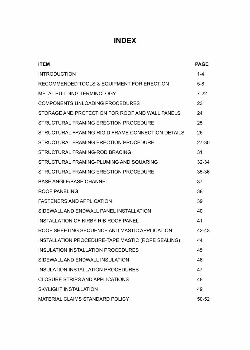
INDEX
ITEM PAGE
INTRODUCTION 1-4
RECOMMENDED TOOLS & EQUIPMENT FOR ERECTION 5-8
METAL BUILDING TERMINOLOGY 7-22
COMPONENTS UNLOADING PROCEDURES 23
STORAGE AND PROTECTION FOR ROOF AND WALL PANELS 24
STRUCTURAL FRAMING ERECTION PROCEDURE 25
STRUCTURAL FRAMING-RIGID FRAME CONNECTION DETAILS 26
STRUCTURAL FRAMING ERECTION PROCEDURE 27-30
STRUCTURAL FRAMING-ROD BRACING 31
STRUCTURAL FRAMING-PLUMING AND SQUARING 32-34
STRUCTURAL FRAMING ERECTION PROCEDURE 35-36
BASE ANGLE/BASE CHANNEL 37
ROOF PANELING 38
FASTENERS AND APPLICATION 39
SIDEWALL AND ENDWALL PANEL INSTALLATION 40
INSTALLATION OF KIRBY RIB ROOF PANEL 41
ROOF SHEETING SEQUENCE AND MASTIC APPLICATION 42-43
INSTALLATION PROCEDURE-TAPE MASTIC (ROPE SEALING) 44
INSULATION INSTALLATION PROCEDURES 45
SIDEWALL AND ENDWALL INSULATION 46
INSULATION INSTALLATION PROCEDURES 47
CLOSURE STRIPS AND APPLICATIONS 48
SKYLIGHT INSTALLATION 49
MATERIAL CLAIMS STANDARD POLICY 50-52
INTRODUCTION
This ERECTION PROCEDURE is intended to provide Kirby Builders and/or erectors with recommended procedures for erecting Kirby buildings as safely and efficiently as possible. However, Kirby Building Systems is not liable for, and does not guarantee the quality of erection, nor does KBS assume any responsibility for building defects that may be attributed to improper erection techniques, or the negligence of other parties.
CORRECTION OF MINOR ERRORS :
A. All erection work will be treated as outlined in the American Institute of Steel Construction Code of Standard Practices for Steel Buildings and Bridges, Section 7, which deals with the correction of errors in situations where the material is not being erected by the fabricator and which reads in substance as follows : The correction of minor misfits by moderate amounts of reaming, grinding, welding or cutting, and the drawing of elements into line with drift pins, shall be considered to be normal erection operations. Errors that cannot be corrected using the foregoing means, or that require major changes in member or Connection configuration, shall be promptly reported to the Owner’s Designated Representatives for Design and Construction and the Fabricator by the Erector, to enable the responsible entity to either correct the error or approve the most efficient and economical method of correction to be used by others.
B. In cases where the Builder/Erector believes there are errors in shop fabrication that prevent the proper assembling and fitting of parts by the use of drift pins, reaming, chipping or cutting, the Builder/Erector shall immediately report such matters to the local Kirby Sales Office so Kirby may either correct the error or approve the method and cost of the correction to be made. The Builder/Erector shall furnish a clear description of the problem in his report to Kirby and shall also furnish a suggested solution and the cost thereof. Kirby shall have the option of :
(1) Replacing the defective material with freight allowed to jobsite by carrier of Kirby’s selection.
OR (2) Authorizing field correction of the problem by a method and at a
cost agreed to by Kirby.
Where field correction is authorized. The Builder/Erector shall be allowed credit for the agreed cost, but in no event shall Kirby be liable for consequential damages.
1
INSPECTION BY KIRBY
Kirby shall have the right to inspect from time to time all erection work being carried on by the Builder or by others. It shall be the responsibility of the Builder/Erector to finish permits, if required, for entry to the job site for the inspection and Builder/Erector shall provide equipment (ladders level etc.) for such inspection. If requested, Builder/Erector will receive a copy of the Inspection Report. In the event erection errors are detected at the time of the inspection, the Builder/Erector will be notified of the errors in writing with a suggested method of correction.
In the event the errors are not corrected by the Builder/Erector, the owner will be notified in writing by Kirby with a copy of the original report included with the owner notification. A copy of the notification to the owner will be forwarded to the Builder/Erector. Kirby shall have no liability to the Builder/Erector or to any customer for defective workmanship in the erection of buildings including by way of description, but not by way of limitations, defects arising from loose connections, missing parts, roof leaks, damaged sheets, omission of sealer, of closure, scratched surfaces, poor alignment, inadequate drainage or defects arising out of materials furnished and or installed by Builder/Erector or others. The Builder/Erector agrees to indemnify and hold harmless from any and all claims which may or might be made against Kirby by any customer or owner arising from or growing out defects in the erection of any Kirby Building erected by or under the direction of, or for the account of the builder and or erector.
STORAGE AND PROTECTION OF COVERING :
A. When Aluminium, galvanized, or the galvanized prepainted coating on piled flat sheets or nested formed sheets or galvanized purlins or girts become wet from rain, natural condensation, or other causes, white rust may result. This may occur either in transit or in storage at the job site.
B. Formed prepainted sheets must be protected from moisture in the same manner as plain galvanized sheets until boldly exposed to the weather. The sheets must be properly packaged and stored, otherwise, white rust may develop at minute cracks in the paint and at the cut edges.
C. It is important on receipt of material, to examine packages for damage. Builders and/or erectors, are encouraged to take prompt action where cuts, tears, or other damage is evident. If a small amount of moisture is present, the sheets should be dried before restacking or storage. Damp sheets should never be restacked until thoroughly dry.
D. Roofing and siding sheets should be erected as soon as possible after
2
3
their arrival at the jobsite. If temporary storage is absolutely necessary, they should be stored indoors. Where indoor storage is not possible, the procedure shown in this MANUAL must be followed to prevent the entry of moisture into the bundle and consequent storage stain.
CLAIMS
It is the responsibility of the owner, Builder or Erector to make an inspection upon arrival of all products shipped to the Customer, Builder or Erector.
It is the responsibility of the builder or erector to report such claims for shortages or defective material immediately to the owner, or customer to enable him to file a claim for the shortage or defective material.
If packaged items are found to contain shortages or defective material, these must be reported to Kirby, in writing, within 30 days after receipt of the shipment.
All claims must be reported in detail giving part numbers, description and length. This information may be obtained directly from the Bill of Materials furnished with the building.
See Appendix ‘1’ for Kirby’s Claims Policy. Please read carefully and follow procedure outlined therein.
ERECTION
A. Before starting Erection, make sure that you have a complete set of Erection drawings marked “For Construction”. The cover sheet of Kirby Erection drawings lists all the drawings in the set along with the latest revision number and date.
B. It is the Builder/Erector’s responsibility for mobilization, receiving, off loading and furnishing necessary tools for the proper erection of a Kirby Building.
C. The structure should be adequately braced at all times before raising the next component. The structure must be secured with temporary or permanent bracing before release of raising equipment and at the end of the day, week ends or other shutdowns.
When commencing erection of the building, the first braced bay must be erected with all wind bracing, eave struts, purlins, girts and flange braces completely installed and all bolts properly tightened to make certain that
the building is properly braced. (See appropriate pages that follow in this manual).
D. All joints should be made up and all bolts in place before releasing raising equipment.
E. Until the first run of roof sheets is secured, temporary scaffold should be used to start sheeting so that sheeters will have something to stand on. See proper method of walking on the roof described in the sheeting section of this Manual.
F. All sheeters should be cautioned regarding roof openings. Any uncovered openings should be properly guarded.
G. Workers should never slide down columns and other structural members. Ladders should be used to get on and off the building. Wall girts and diagonal braces should not used as ladders.
4
5
RECOMMENDED TOOLS & EQUIPMENTFOR ERECTION
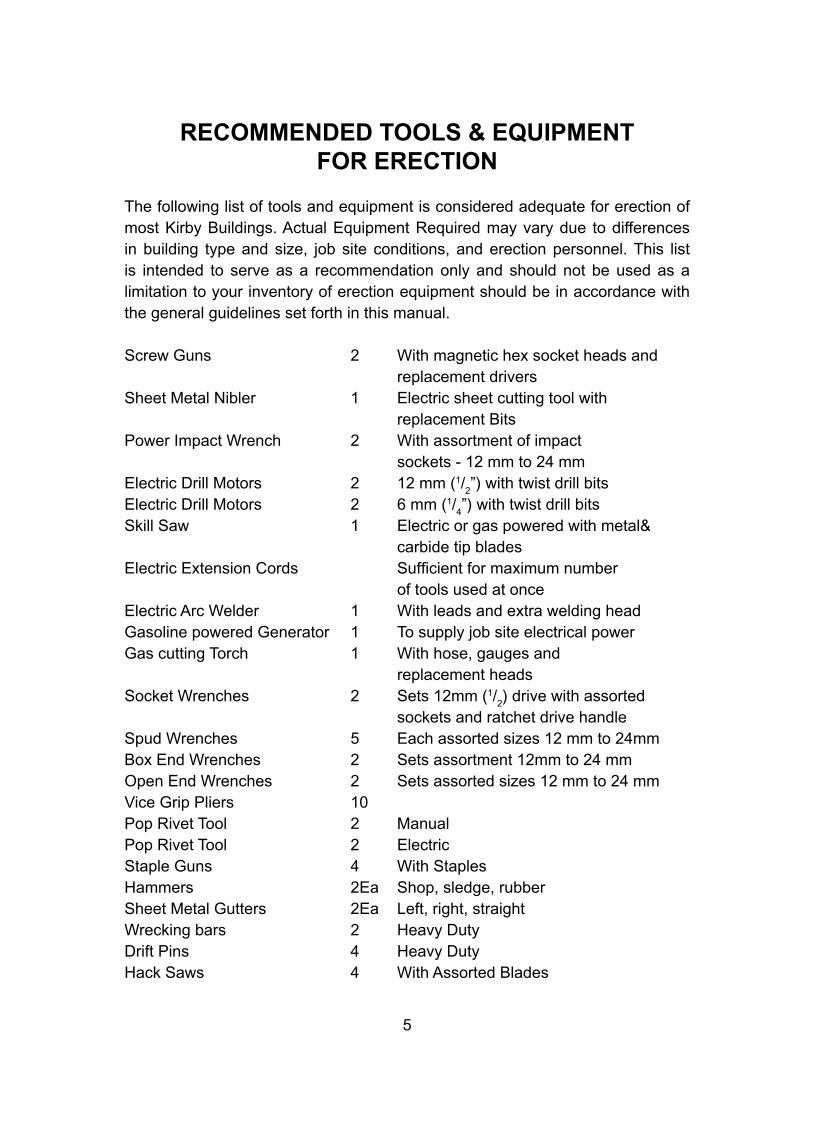
The following list of tools and equipment is considered adequate for erection of most Kirby Buildings. Actual Equipment Required may vary due to differences in building type and size, job site conditions, and erection personnel. This list is intended to serve as a recommendation only and should not be used as a limitation to your inventory of erection equipment should be in accordance with the general guidelines set forth in this manual.
Screw Guns 2 With magnetic hex socket heads and replacement driversSheet Metal Nibler 1 Electric sheet cutting tool with replacement BitsPower Impact Wrench 2 With assortment of impact sockets - 12 mm to 24 mmElectric Drill Motors 2 12 mm (1/
2”) with twist drill bits
Electric Drill Motors 2 6 mm (1/4”) with twist drill bits
Skill Saw 1 Electric or gas powered with metal& carbide tip bladesElectric Extension Cords Sufficient for maximum number of tools used at onceElectric Arc Welder 1 With leads and extra welding headGasoline powered Generator 1 To supply job site electrical powerGas cutting Torch 1 With hose, gauges and replacement headsSocket Wrenches 2 Sets 12mm (1/
2) drive with assorted
sockets and ratchet drive handleSpud Wrenches 5 Each assorted sizes 12 mm to 24mm Box End Wrenches 2 Sets assortment 12mm to 24 mmOpen End Wrenches 2 Sets assorted sizes 12 mm to 24 mmVice Grip Pliers 10Pop Rivet Tool 2 ManualPop Rivet Tool 2 ElectricStaple Guns 4 With StaplesHammers 2Ea Shop, sledge, rubberSheet Metal Gutters 2Ea Left, right, straightWrecking bars 2 Heavy DutyDrift Pins 4 Heavy DutyHack Saws 4 With Assorted Blades
6
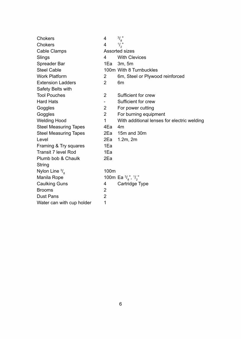
Chokers 4 3/8”
Chokers 4 1/2”
Cable Clamps Assorted sizesSlings 4 With ClevicesSpreader Bar 1Ea 3m, 5mSteel Cable 100m With 8 TurnbucklesWork Platform 2 6m, Steel or Plywood reinforcedExtension Ladders 2 6mSafety Belts withTool Pouches 2 Sufficient for crewHard Hats - Sufficient for crewGoggles 2 For power cuttingGoggles 2 For burning equipmentWelding Hood 1 With additional lenses for electric weldingSteel Measuring Tapes 4Ea 4mSteel Measuring Tapes 2Ea 15m and 30mLevel 2Ea 1.2m, 2mFraming & Try squares 1EaTransit 7 level Rod 1EaPlumb bob & Chaulk 2EaStringNylon Line 3/
8 100m
Manila Rope 100m Ea 3/8”, 1/
2”
Caulking Guns 4 Cartridge TypeBrooms 2Dust Pans 2Water can with cup holder 1
7
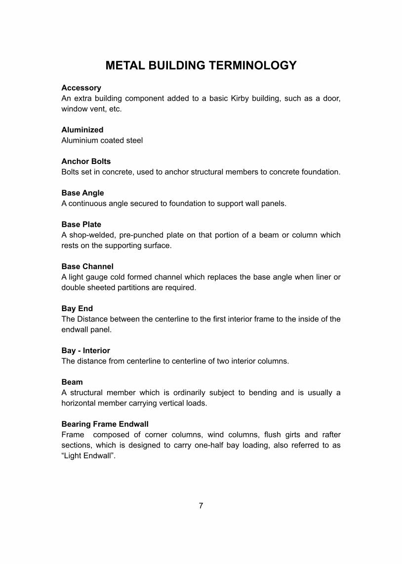
METAL BUILDING TERMINOLOGY
AccessoryAn extra building component added to a basic Kirby building, such as a door, window vent, etc.
AluminizedAluminium coated steel
Anchor BoltsBolts set in concrete, used to anchor structural members to concrete foundation.
Base AngleA continuous angle secured to foundation to support wall panels.
Base PlateA shop-welded, pre-punched plate on that portion of a beam or column which rests on the supporting surface.
Base ChannelA light gauge cold formed channel which replaces the base angle when liner or double sheeted partitions are required.
Bay EndThe Distance between the centerline to the first interior frame to the inside of the endwall panel.
Bay - InteriorThe distance from centerline to centerline of two interior columns.
BeamA structural member which is ordinarily subject to bending and is usually a horizontal member carrying vertical loads.
Bearing Frame EndwallFrame composed of corner columns, wind columns, flush girts and rafter sections, which is designed to carry one-half bay loading, also referred to as “Light Endwall”.

Brace Angles/RodsAngles or rods primarily on Roof and sidewalls or RF (Rigid Frame) or BC (Beam & Column) buildings for transferring wind force to foundation and aiding in plumbing the structure.
Bridge CraneA material handling system usually within a building which moves longitudinally on a runway constructed of rails and beams.
BridgingStructural members used to give weak axis stability to joists or purlins.
Built-Up Member or SectionA structural member, usually an “I” section, made from individual web, flange and base plates by welding them together.
Built-Up RoofA roof composed of layered felt or jute, saturated with tar, with each layer set by mopping a hot tar or asphalt.
Butterfly CanopyA free standing, single or double column roof structure having a valley gutter at the centerline of the building having the outer edge of the roof projecting upwards.
Butt Plate (or Splice Plate)The pre-punched end plate of a structural member which usually rests against a matching plate of another member in forming a bolted connection.
By-Framed GirtsGirts which overlap at outside column flange to form a continuous member.
“C” SectionA member cold-formed from steel coil in the shape of “C” used primarily in bearing frame endwalls and framed openings.
CamberA predetermined curvature designed into a structural member to offset the anticipated deflection when load is applied.
CanopyAny overhanging or projecting structure with extreme end usually unsupported.
8
9
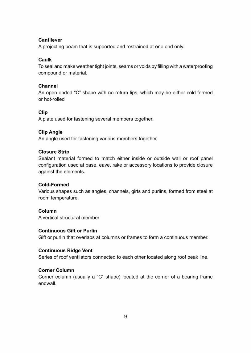
CantileverA projecting beam that is supported and restrained at one end only.
CaulkTo seal and make weather tight joints, seams or voids by filling with a waterproofing compound or material.
ChannelAn open-ended “C” shape with no return lips, which may be either cold-formed or hot-rolled
ClipA plate used for fastening several members together.
Clip AngleAn angle used for fastening various members together.
Closure StripSealant material formed to match either inside or outside wall or roof panel configuration used at base, eave, rake or accessory locations to provide closure against the elements.
Cold-FormedVarious shapes such as angles, channels, girts and purlins, formed from steel at room temperature.
ColumnA vertical structural member
Continuous Gift or PurlinGift or purlin that overlaps at columns or frames to form a continuous member.
Continuous Ridge VentSeries of roof ventilators connected to each other located along roof peak line.
Corner ColumnCorner column (usually a “C” shape) located at the corner of a bearing frame endwall.
Corner TrimPreformed sheet metal trim used to close the junction of side and endwall sheets.
Crane RailTrack upon which a top running crane moves (usually hot-rolled A.S.C.E. Rails).
Crane Runway BeamSupport for bridge crane.
CurbRaised flashing around a roof accessory to provide water tightness at the roof opening
Curtain WallPerimeter wall panels which carry only their own weight.
DamperA baffle used to open or close the throat of ventilators.
Dead LoadThe weight of the structure itself plus any permanent stationary loads.
DeflectionThe transverse displacement of a structural member in the direction of load and measured from its no-load position.
Diaphragm ActionThe action of Kirby Wall panels on flush-framed walls to act as one unit to resist longintudinal wind force.
DownspoutA hollow rectangular, square or round tubular section used to carry water from a gutter to the ground.
DriftpinA tapered pin used to align holes in steel members to be connected. Also called “Spud Wrench”
10
11
EaveThe line along the top of the sidewall, formed by the intersection of roof and wall panels.
Eave CanopyA roof extension beyond the sidewall of a building. May also be cantilevered below the eave.
Eave HeightThe vertical dimension from finished floor to top of eave strut.
Eave StrutStructural member at the eave to support roof and wall panels; also transmits forces due to wind on endwall from roof brace rods to wall brace rods.
Eave Strut GussetA small gusset shop-welded to main frame on RF and BC buildings to support eave struts and afford alignment with by-framed girts.
Eave TrimTrim used to close off top of sidewall panels in lieu of eave gutter.
ErectionThe on-site assembly of pre-engineered components to form complete structure.
Erection DrawingsDrawings prepared specifically for each building, showing piece mark, and location of all components.
Expansion JointA break of space in construction to allow for thermal expansion and contraction.
FasciaDecorative trim or panel projecting from the face of a wall.
Fixed BaseA vertical structural member, bolted to and positioned at 900 to a sidewall column to provide additional base fastening and to prevent column rotation.
FlangeThe projecting edge of a structural member.
Flange BraceA brace from flange of column or rafter to git or purlin to provide lateral support and stability.
FlashingA sheet metal closure to insure weather-tightness.
FootingA pad or mat, usually concrete, located under a column, wall, or other structural member, used to distribute loads from the member into supporting soil.
FoundationThe substructure on which a building rests.
FramePrimary structural members, made up of columns and rafters, which support the secondary framing.
Framed OpeningOpening in a wall, roof or floor that is framed with secondary members.
GableA triangular portion of the endwall of building, directly under the sloping roof and at the bottom of the eave strut line.
GaugeThickness range of steel (24, 26 etc). Distance between holes punched in flanges, base or splice plates.
GalvanizedZinc-coated steel.
GirderA main horizontal or near horizontal structural member that supports vertical loads.
12
13
GirtA secondary horizontal structural member attached to sidewall or endwallcolumns to which wall covering is attached and supported horizontally : usually a cold-formed “Z” shape.
Glaze or GlazingThe process of installing glass in window and door openings.
GroutA mixture of cement, sand and water used to fill cracks and cavities. Often used under base plates or leveling plates to obtain uniform bearing surfaces.
Gusset PlateA steel plate used to connect two or more structural members in the same plane.
GutterThe member used to collect and carry rain water off the roof.
Hair-PinReinforcing bar used to help transfer anchor bolt shear (due to column thrust) to concrete floor mass. The “U” shaped hair pin wraps around the anchor bolts in side the slab.
HaunchAlso knee. The deepened portion of a column or rafter, designed to accommodate the high stress where column and rafter intersect and connect.
Haunch BraceA diagonal brace between eave strut and haunch.
HeaderA horizontal member over a wall opening.
Header TrimTrim used above a wall opening.
High Strength BoltsAny bolt made from steel having a tensile strength in excess of 100,00 pounds per square inch (PSI). Some examples are ASTM A-325, JIS 11.86.
High Tensile SteelStructural steel having a yield stress in excess of 36,000 pounds per square inch.
HIP RoofA roof which rises by inclined planes from all four sides.
Hot Rolled ShapesSteel sections (angles, channels, I-Beams, etc.) which are formed by rolling mills while the steel is in a semi-molten state.
ImpactShock loads caused by dynamic application.
Inner LinerLiner panelling on the inside of walls.
Inside Corner TrimTrim which flashes inside corners
InsulationAny material used in building construction to reduce heat transfer.
Intermediate BayA Distance between two main frames within a building. Other than end frames.
Jack BeamA beam used to support another beam or rafter to eliminate a column support.
Jack TrussTruss used to support another beam, truss or rafter to eliminate a column support.
JambA side column of a doorway or opening.
JIB CraneA cantilevered boom or horizontal beam with hoist and trolley. This lifting machine may pick up loads in all or part of a circle around the column to which it is attached.
14
15
JoistBeam for supporting the floor or roof.
KIPKilo-Pound (1000 #)
Kirby DeckStandard panel used as a form (shuttering) on mezzanine floors or as a deck panel over which concrete is poured.
Kirby RibStandard panel used for roof, liner, soffits and partitions.
Kirby Wall PanelStandard panel used on exterior walls and facades.
Knee (or Haunch)The connecting area of a column and rafter of a structural frame.
Knee BraceA diagonal brace designed to resist horizontal loads usually from wind or moving material handling equipment. This brace member normally has the lower end connected to a column and the upper end connected to a rafter or eave strut.
Lean-ToA structure having only one slope or pitch and depending on another structure for partial support.
Liner PanelSheeting on inside of building; may be either full or partial height.
LIPA flange stiffner on cold formed sections.
Live LoadAny moving or variable load which the structure must support which is not permanently attached to the structure.
LouverAn opening provided with fixed or adjustable blades to allow air flow.
MansardA tilted fascia system mounted to the roof, outside the steel line, and above the roof line to form a decorative fascia appearance and hide the roof line.
Main or Primary FramingSteel Frames which support secondary framing members such as girts, purlins or eave struts.
MasticCaulking or sealant furnished in Rolls, Normally used in sealing roof panel laps.
Mezzanine BeamPrimary framing for mezzanines.
Mezzanine JoistSecondary framing for mezzanines
MomentForce times distance (torque)
Moment ConnectionA joint capable of transmitting moment to another member of the system.
MonitorsSuperstructure located above the ridge of the building used for ventilation or additional light.
MullionsVertical member connecting two windows located side by side.
MS-Multi-SpanMore than one building tied together : Multiple gable buildings.
NibblerAl electric hand tool used to cut steel roof or wall sheet openings.
ParapetThat portion of the wall which extends vertically above the roof line to form a fascia-type appearance to hide roof slope.
16
17
PartitionAn interior dividing wall
Peak BoxA pre-fabricated trim piece that trims rake trim connection at the apex of gable, and bears a metal plate with the Kirby Trade Mark.
Peak PanelKirby Rib panel located along building ridge, conforms to roof slope and configuration.
PierA concrete structure designed to transfer vertical load from the base of a column to a footing.
PilasterA masonry column built into a wall and projecting from it.
Pop RivetA small headed pin with expandable shank for joining light gauge metal. Typically used for flashing trim etc.
Portal Frame BraceColumns and horizontal beam substituted for standard bracing in areas where rod bracing is not allowed because of access requirements.
Primer PaintInitial coat of paint applied at factory to structural framing for protection against elements during shipping and erection only.
PurlinA secondary member, usually cold-formed horizontal structural member located in the roof to support roof panels, that is itself supported by the primary structural framing. Generally, purlins in Kirby Buildings overlap at frames to form acontinuous design.
Purlin Extension CanopyCantilevered continuation of Roof at rake line.
Purlin StrutAdditional purlin added at or near intersection of wind bracing members at the rigid frame where a series of wind bracing is required in the roof plane. This strut may or may not be a continuous member through out the length of the building.
RafterA fabricated primary structural member with parallel flanges that extends from haunch to apex. Any beam used in a primary frame to support purlins.
RakeThe intersection of roof and endwall.
Rake AngleAngle attached to purlins at rake for attachment of endwall sheets.
ReactionsForces required to resist loads from a structure.
Reinforcing SteelSteel rods placed in concrete to take tension. Compression and shear stresses.
RidgePeak of a gabled building (apex)
(RF)-Rigid FrameA clearspan structure. Characterized by tapered columns, tapered haunches and rafter beams.
Roof Slope or PitchSlope of a roof place expressed as a ratio of vertical rise per unit of horizontal run.
Sag Rod or Sag AngleTie rods or angles to support bottom purlin flanges against compression buckling due to special wind force.
ScreedingThe process of striking of the excess concrete to bring the top surface to proper finish and elevation.
SealantAny material which is used to close up cracks or joints to protect against leaks.
18
19
Secondary FramingFraming consisting of minor load bearing members of a structure, such as purlins, girts, eave struts, etc.
Seismic ForcesForces due to earth movement or earthquake.
Self-Drilling Screw (SDS)A fastener which combines the functions of drilling and tapping. Used for attaching panels to purlins and girts.
Self-Tapping Screw (STS)A Fastener which taps its own threads in a pre-drilled hole. Used for attaching panels to purlins and girts. For panel laps, and for trim and flashing.
Sheeting AngleAn angle used for securing sheeting.
ShimsA piece of steel used to level or square base plates.
Shipping ListA list that enumerates each piece to be shipped.
SillThe bottom horizontal framing member of a door or window opening.
Single SlopeA sloping roof with one slope surface.
SkylightTranslucent fiberglass panel formed like Kirby Rib used on roof or like Kirby Wall used on walls in place of pre-determined panels to supply natural light to interior of building.
Slide DoorA single or double leaf door which opens horizontally by means of overhead trolleys.
SoffitThe underside covering of a canopy or purlins extension; usually Kirby Rib.
Soil PressureAllowable load per unit area a substructure slab may exert on a given soil.
Space SaverKirby’s straight column, slope beam rafter building. Girts are flush framed within the column.
SpanWidth of building inside to inside of wall panels (sidewall to sidewall).
SpliceA connection in a structural member.
Splice PlatePlate used to connect two steel members.
Spud WrenchSee “Drift Pin”
Steel LineThe outside perimeter of structural steel or inside of wall panels.
StiffenerA member used to strengthen a plate against lateral or local buckling. Usually a bar welded perpendicular to the longitudinal Axis of the member. Large concentrated loads such as crane loads usually require stiffeners at the point of connection.
Stitch ScrewScrew used to fasten panel to panel at side laps.
ThresholdAn aluminium extrusion kick plate that spans between jambs beneath a personnel walk door leaf.
ThrustHorizontal force developed as a result of a load being applied to a rigid frame.
TieA structural member that tends to lengthen under stress. (i.e. wind brace rod)
20
21
Torque WrenchA wrench containing an adjustable mechanism for measuring and controlling the amount of torque of turning force to be exerted - used to tighten nuts on high strength bolts.
TrimLight gauge sheet metal used around building openings and at intersections of roofs, walls, etc., often referred to as flashing.
TrussA structure composed of three or more members so designed and connected that the structure as a whole acts as a beam and the individual members are subjected primarily to longitudinal stress.
Turn of Nut MethodA method of tightening bolts in a connection. A rotation of the nut through 1/
2 to 3/
4
turn beyond a ‘snug’ position will produce at least the desired minimum tension on the bolt. (“snug” is defined as the point at which the material between the bolt head and the nut is rigid. If power tools are used, “snug” would be the point at which the wrench begins to impact).
Unit StressStress per unit area.
Unsupported ColumnThe condition that exists when a column has no lateral support. A column is unsupported when there are no braces attached to the flanges.
Uplift StrapLight gauge metal straps running continuously across the purlins from the base of the building at one side to the other.These straps are normally used on buildings with a 3/
10 roof slope, buildings with
asbestos sheeting, unsheeted buildings and in buildings with longer bays.
Valley GutterOversized gutter located at the junction of the eaves where buildings are joined in multiple, sidewall to sidewall, junction of parapet wall and roof, junction of sidewall and endwall of buildings forming a T or L shape and at the intersection of roof planes in a butterfly roof.
WainscotA liner starting at floor but less than ceiling height.
Wall, BearingWall capable of supporting a structural system.
Wall, Non-BearingWall not capable of supporting a structural system.
WebThe part of a channel, purlin, girt, column or rafter between the flanges.
Web MembersThe system of members connecting the chords of a truss.
Wind BentA wind bracing system used in sidewalls when brace rods cannot be used.
Wind ColumnA column located in endwalls of building designed to carry required wind loads.
Yield StressThe stress at which the strain ceases to be directly proportional to the stress.
“Z” SectionA girt or purlin : a member cold-formed from steel sheet coil in the shape of a block “Z” with stiffener lips.
22
23
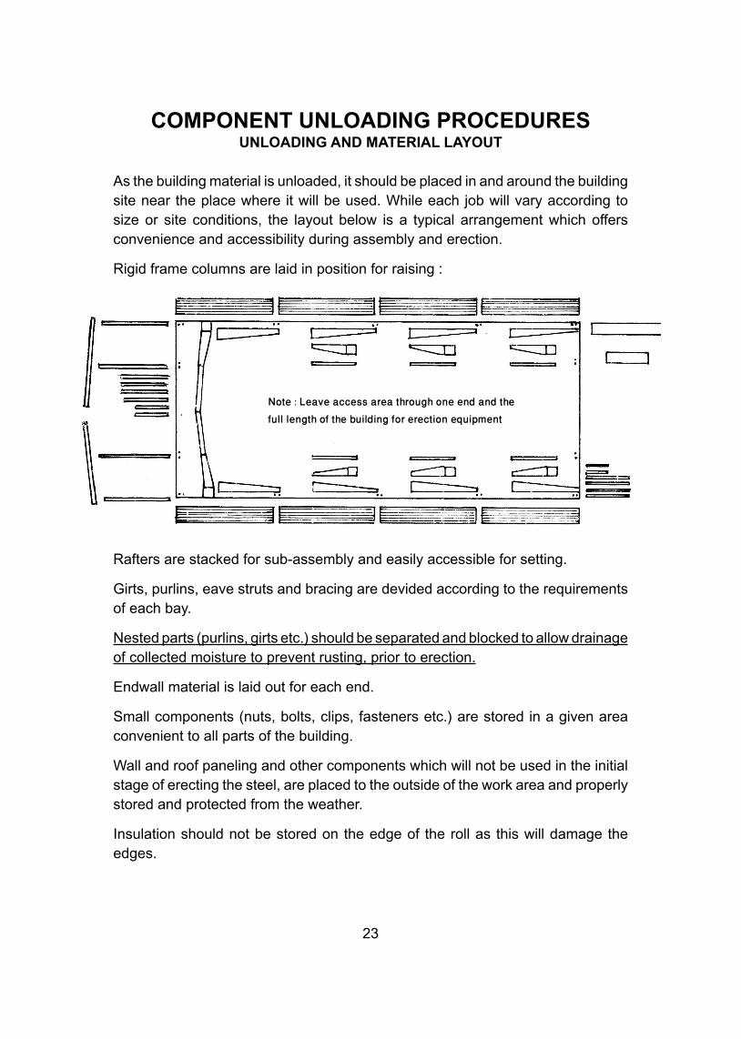
COMPONENT UNLOADING PROCEDURESUNLOADING AND MATERIAL LAYOUT
As the building material is unloaded, it should be placed in and around the building site near the place where it will be used. While each job will vary according to size or site conditions, the layout below is a typical arrangement which offers convenience and accessibility during assembly and erection.
Rigid frame columns are laid in position for raising :
Rafters are stacked for sub-assembly and easily accessible for setting.
Girts, purlins, eave struts and bracing are devided according to the requirements of each bay.
Nested parts (purlins, girts etc.) should be separated and blocked to allow drainage of collected moisture to prevent rusting, prior to erection.
Endwall material is laid out for each end.
Small components (nuts, bolts, clips, fasteners etc.) are stored in a given area convenient to all parts of the building.
Wall and roof paneling and other components which will not be used in the initial stage of erecting the steel, are placed to the outside of the work area and properly stored and protected from the weather.
Insulation should not be stored on the edge of the roll as this will damage the edges.
Note : Leave access area through one end and the full length of the building for erection equipment
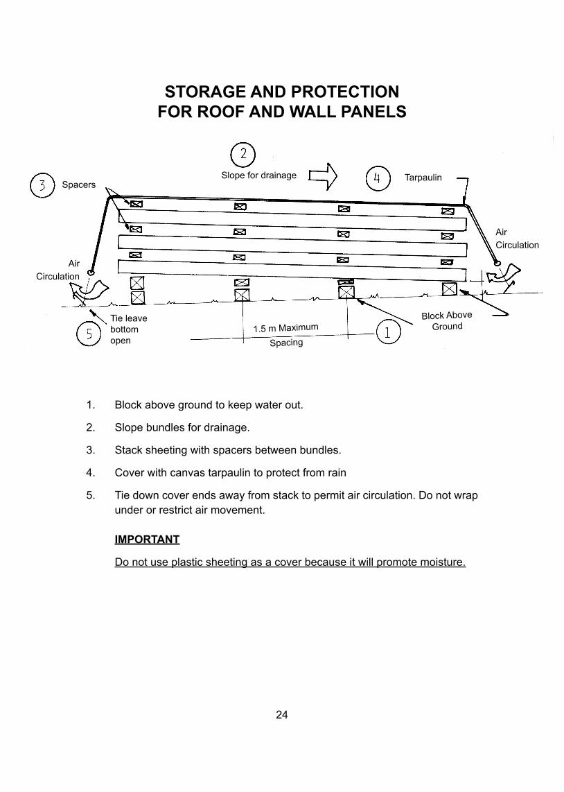
STORAGE AND PROTECTIONFOR ROOF AND WALL PANELS
24
1. Block above ground to keep water out.
2. Slope bundles for drainage.
3. Stack sheeting with spacers between bundles.
4. Cover with canvas tarpaulin to protect from rain
5. Tie down cover ends away from stack to permit air circulation. Do not wrap under or restrict air movement.
IMPORTANT
Do not use plastic sheeting as a cover because it will promote moisture.
SpacersSlope for drainage Tarpaulin
AirCirculation
AirCirculation
Tie leavebottomopen
1.5 m Maximum
Spacing
Block AboveGround
25
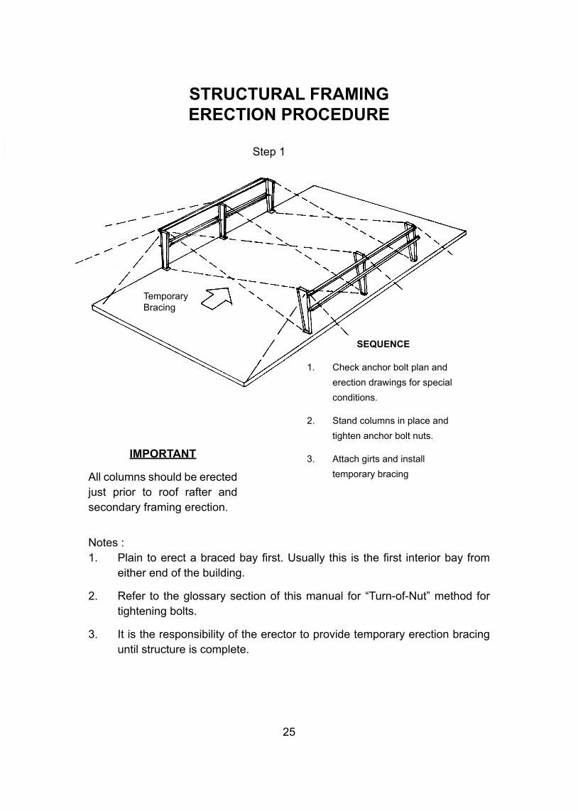
STRUCTURAL FRAMINGERECTION PROCEDURE
Notes :1. Plain to erect a braced bay first. Usually this is the first interior bay from either end of the building.
2. Refer to the glossary section of this manual for “Turn-of-Nut” method for tightening bolts.
3. It is the responsibility of the erector to provide temporary erection bracing until structure is complete.
IMPORTANT
All columns should be erected just prior to roof rafter and secondary framing erection.
SEQUENCE
1. Check anchor bolt plan and
erection drawings for special
conditions.
2. Stand columns in place and
tighten anchor bolt nuts.
3. Attach girts and install
temporary bracing
TemporaryBracing
Step 1
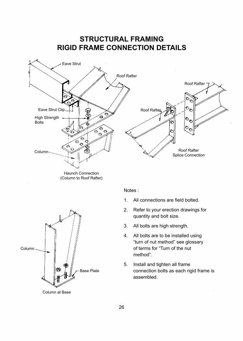
STRUCTURAL FRAMINGRIGID FRAME CONNECTION DETAILS
Notes :
1. All connections are field bolted.
2. Refer to your erection drawings for quantity and bolt size.
3. All bolts are high strength.
4. All bolts are to be installed using “turn of nut method” see glossary of terms for “Turn of the nut method”.
5. Install and tighten all frame connection bolts as each rigid frame is assembled.
26
Eave Strut
Roof Rafter
Roof Rafter
Eave Strut Clip
High StrengthBolts
Column
Roof Rafter
Haunch Connection(Column to Roof Rafter)
Roof RafterSplice Connection
Column
Base Plate
Column at Base
27
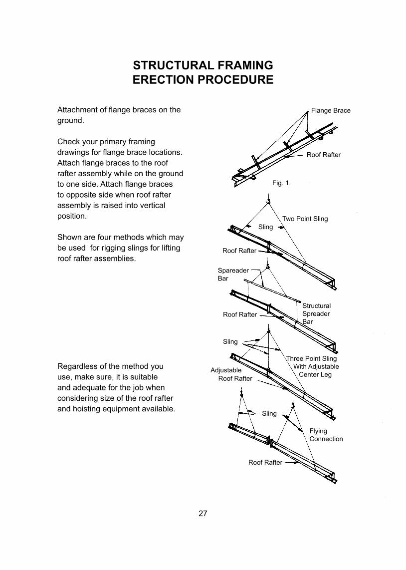
STRUCTURAL FRAMINGERECTION PROCEDURE
Attachment of flange braces on the ground.
Check your primary framing drawings for flange brace locations. Attach flange braces to the roof rafter assembly while on the ground to one side. Attach flange braces to opposite side when roof rafter assembly is raised into vertical position.
Shown are four methods which may be used for rigging slings for lifting roof rafter assemblies.
Regardless of the method you use, make sure, it is suitable and adequate for the job when considering size of the roof rafter and hoisting equipment available.
Flange Brace
Roof Rafter
Fig. 1.
Two Point SlingSling
Roof Rafter
SpareaderBar
StructuralSpreaderBar
Roof Rafter
Sling
Three Point Sling With Adjustable Center Leg
AdjustableRoof Rafter
Roof Rafter
Sling
FlyingConnection
28
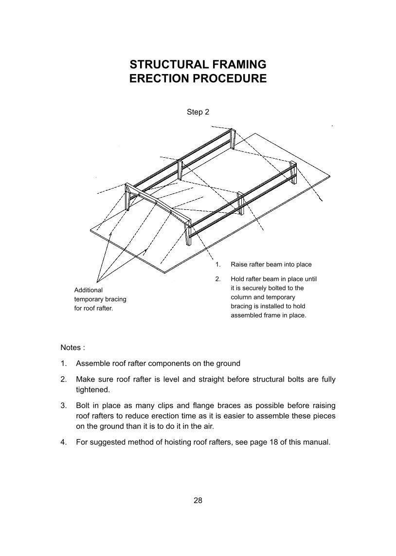
Notes :
1. Assemble roof rafter components on the ground
2. Make sure roof rafter is level and straight before structural bolts are fully tightened.
3. Bolt in place as many clips and flange braces as possible before raising roof rafters to reduce erection time as it is easier to assemble these pieces on the ground than it is to do it in the air.
4. For suggested method of hoisting roof rafters, see page 18 of this manual.
1. Raise rafter beam into place
2. Hold rafter beam in place until it is securely bolted to the column and temporary bracing is installed to hold assembled frame in place.
Additionaltemporary bracingfor roof rafter.
STRUCTURAL FRAMINGERECTION PROCEDURE
Step 2
29
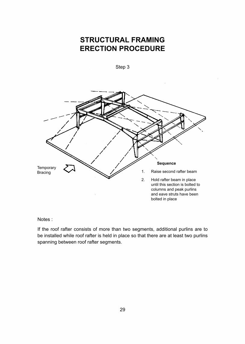
STRUCTURAL FRAMINGERECTION PROCEDURE
Notes :
If the roof rafter consists of more than two segments, additional purlins are to be installed while roof rafter is held in place so that there are at least two purlins spanning between roof rafter segments.
Sequence
1. Raise second rafter beam
2. Hold rafter beam in place until this section is bolted to columns and peak purlins and eave struts have been bolted in place
Temporary Bracing
Step 3
30
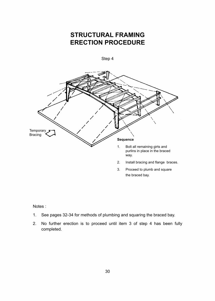
Notes :
1. See pages 32-34 for methods of plumbing and squaring the braced bay.
2. No further erection is to proceed until item 3 of step 4 has been fully completed.
Sequence
1. Bolt all remaining girts and purlins in place in the braced way.
2. Install bracing and flange braces.
3. Proceed to plumb and square
the braced bay.
STRUCTURAL FRAMINGERECTION PROCEDURE
Step 4
Temporary Bracing
31
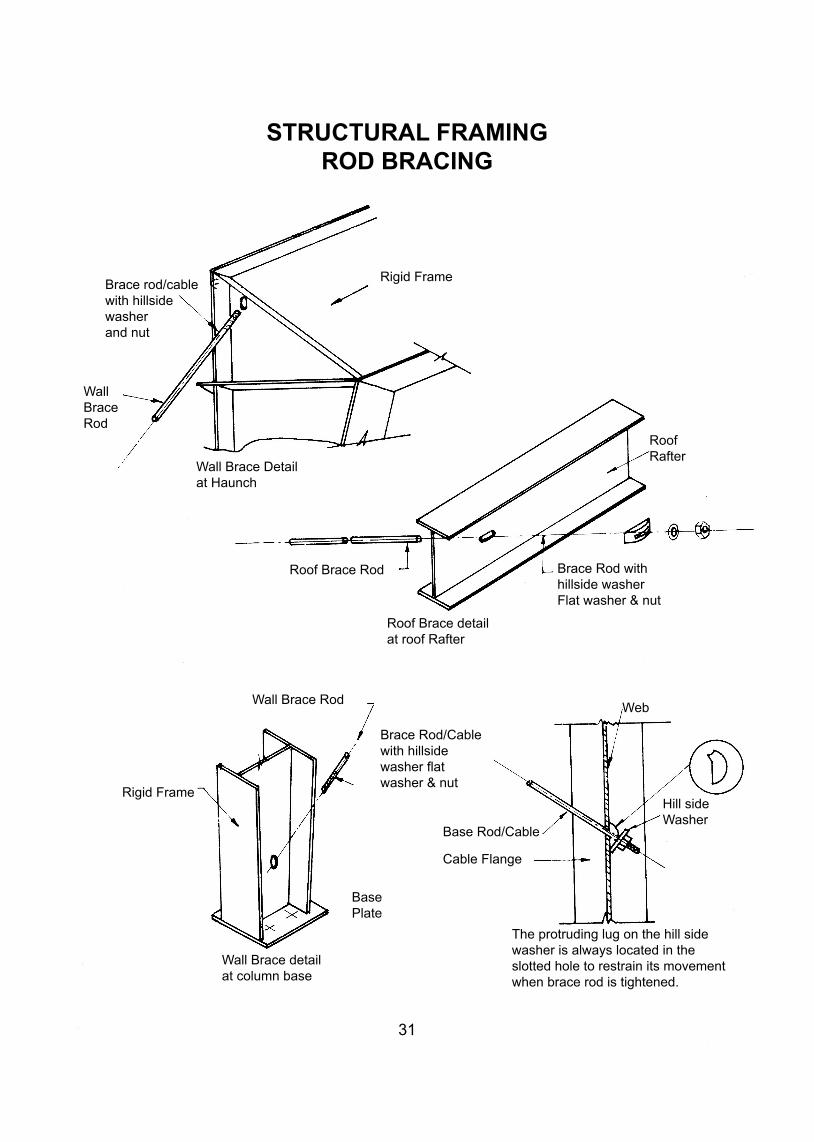
STRUCTURAL FRAMINGROD BRACING
Brace rod/cablewith hillsidewasherand nut
Wall BraceRod
Rigid Frame
RoofRafter
Wall Brace Detailat Haunch
Roof Brace Rod Brace Rod withhillside washer Flat washer & nut
Roof Brace detailat roof Rafter
Wall Brace Rod
Rigid Frame
Brace Rod/Cablewith hillsidewasher flatwasher & nut
BasePlate
Wall Brace detailat column base
The protruding lug on the hill sidewasher is always located in theslotted hole to restrain its movementwhen brace rod is tightened.
Base Rod/Cable
Cable Flange
Web
Hill sideWasher
32
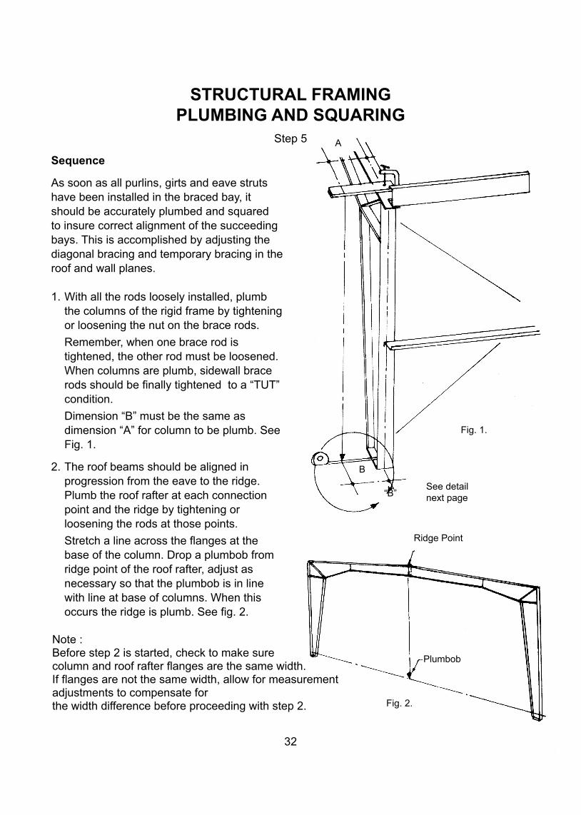
Sequence
As soon as all purlins, girts and eave struts have been installed in the braced bay, it should be accurately plumbed and squared to insure correct alignment of the succeeding bays. This is accomplished by adjusting the diagonal bracing and temporary bracing in the roof and wall planes.
1. With all the rods loosely installed, plumb the columns of the rigid frame by tightening or loosening the nut on the brace rods.
Remember, when one brace rod is tightened, the other rod must be loosened. When columns are plumb, sidewall brace rods should be finally tightened to a “TUT” condition.
Dimension “B” must be the same as dimension “A” for column to be plumb. See Fig. 1.
2. The roof beams should be aligned in progression from the eave to the ridge. Plumb the roof rafter at each connection point and the ridge by tightening or loosening the rods at those points.
Stretch a line across the flanges at the base of the column. Drop a plumbob from ridge point of the roof rafter, adjust as necessary so that the plumbob is in line with line at base of columns. When this occurs the ridge is plumb. See fig. 2.
STRUCTURAL FRAMINGPLUMBING AND SQUARING
Step 5
Note :Before step 2 is started, check to make surecolumn and roof rafter flanges are the same width.If flanges are not the same width, allow for measurementadjustments to compensate forthe width difference before proceeding with step 2.
A
See detailnext page
Fig. 1.
B
“B”
Ridge Point
Plumbob
Fig. 2.
33
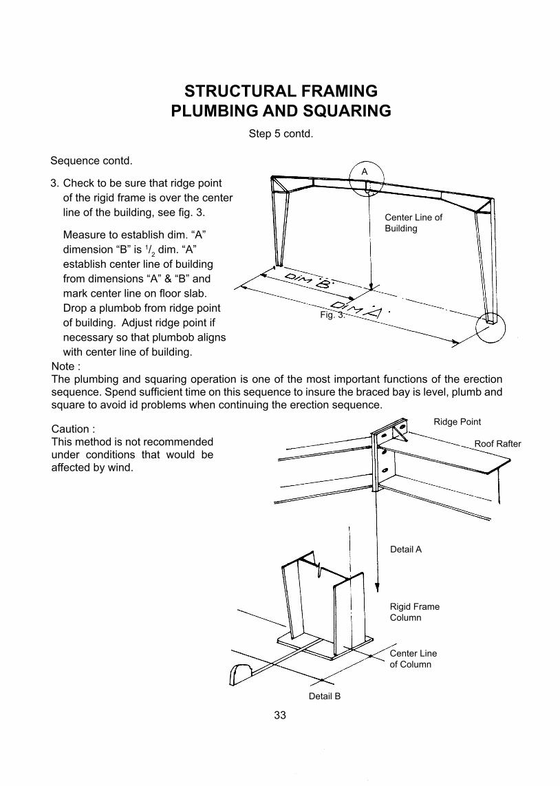
Sequence contd.
3. Check to be sure that ridge point of the rigid frame is over the center line of the building, see fig. 3.
Measure to establish dim. “A” dimension “B” is 1/
2 dim. “A”
establish center line of building from dimensions “A” & “B” and mark center line on floor slab. Drop a plumbob from ridge point of building. Adjust ridge point if necessary so that plumbob aligns with center line of building.
STRUCTURAL FRAMINGPLUMBING AND SQUARING
Step 5 contd.
Note :The plumbing and squaring operation is one of the most important functions of the erection sequence. Spend sufficient time on this sequence to insure the braced bay is level, plumb and square to avoid id problems when continuing the erection sequence.
Caution :This method is not recommended under conditions that would be affected by wind.
Center Line of Building
A
Fig. 3.
Ridge Point
Roof Rafter
Detail A
Rigid FrameColumn
Center Lineof Column
Detail B
34
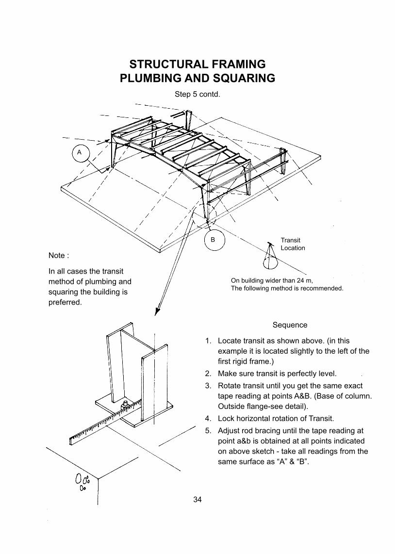
Note :
In all cases the transit method of plumbing and squaring the building is preferred.
STRUCTURAL FRAMINGPLUMBING AND SQUARING
Step 5 contd.
Sequence
1. Locate transit as shown above. (in this example it is located slightly to the left of the first rigid frame.)
2. Make sure transit is perfectly level.
3. Rotate transit until you get the same exact tape reading at points A&B. (Base of column. Outside flange-see detail).
4. Lock horizontal rotation of Transit.
5. Adjust rod bracing until the tape reading at point a&b is obtained at all points indicated on above sketch - take all readings from the same surface as “A” & “B”.
On building wider than 24 m, The following method is recommended.
TransitLocation
B
A
35
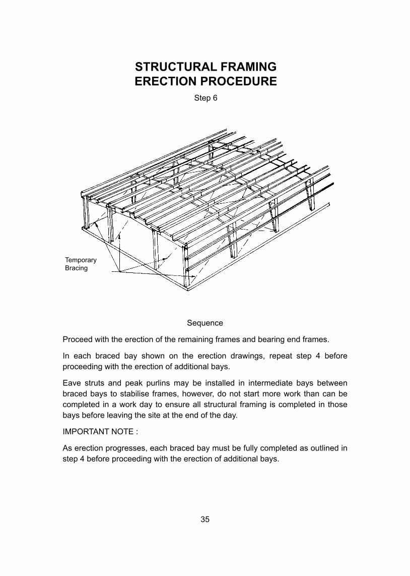
Sequence
Proceed with the erection of the remaining frames and bearing end frames.
In each braced bay shown on the erection drawings, repeat step 4 before proceeding with the erection of additional bays.
Eave struts and peak purlins may be installed in intermediate bays between braced bays to stabilise frames, however, do not start more work than can be completed in a work day to ensure all structural framing is completed in those bays before leaving the site at the end of the day.
IMPORTANT NOTE :
As erection progresses, each braced bay must be fully completed as outlined in step 4 before proceeding with the erection of additional bays.
STRUCTURAL FRAMINGERECTION PROCEDURE
Step 6
TemporaryBracing
36
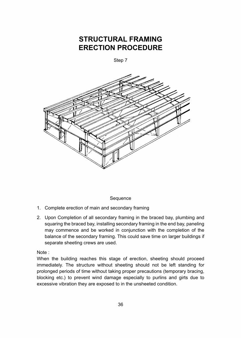
STRUCTURAL FRAMINGERECTION PROCEDURE
Step 7
Sequence
1. Complete erection of main and secondary framing
2. Upon Completion of all secondary framing in the braced bay, plumbing and squaring the braced bay, installing secondary framing in the end bay, paneling may commence and be worked in conjunction with the completion of the balance of the secondary framing. This could save time on larger buildings if separate sheeting crews are used.
Note :When the building reaches this stage of erection, sheeting should proceed immediately. The structure without sheeting should not be left standing for prolonged periods of time without taking proper precautions (temporary bracing, blocking etc.) to prevent wind damage especially to purlins and girts due to excessive vibration they are exposed to in the unsheeted condition.
37
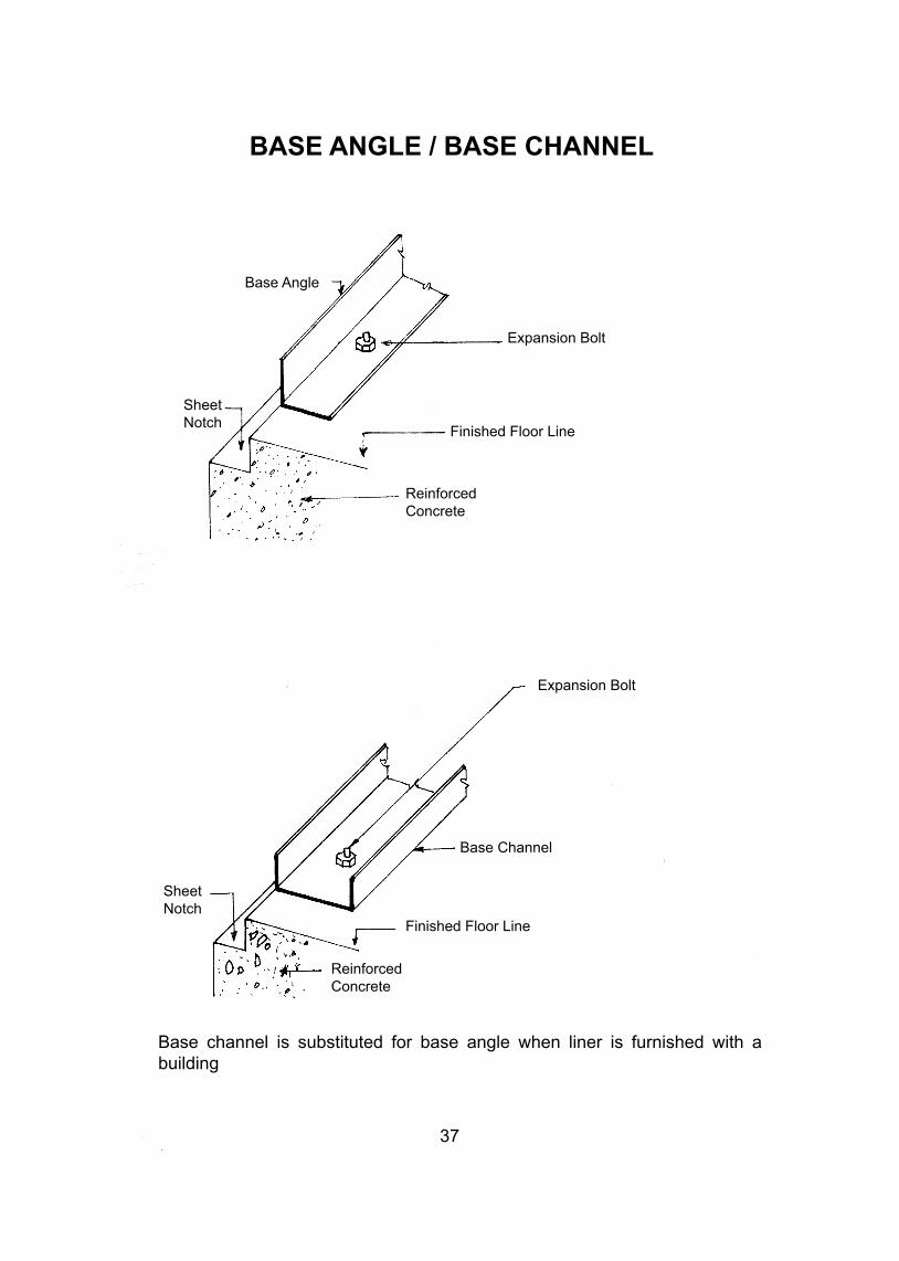
BASE ANGLE / BASE CHANNEL
Base Angle
Expansion Bolt
Finished Floor Line
ReinforcedConcrete
Expansion Bolt
SheetNotch
Base Channel
Finished Floor Line
ReinforcedConcrete
SheetNotch
Base channel is substituted for base angle when liner is furnished with a building
ROOF PANELING
38
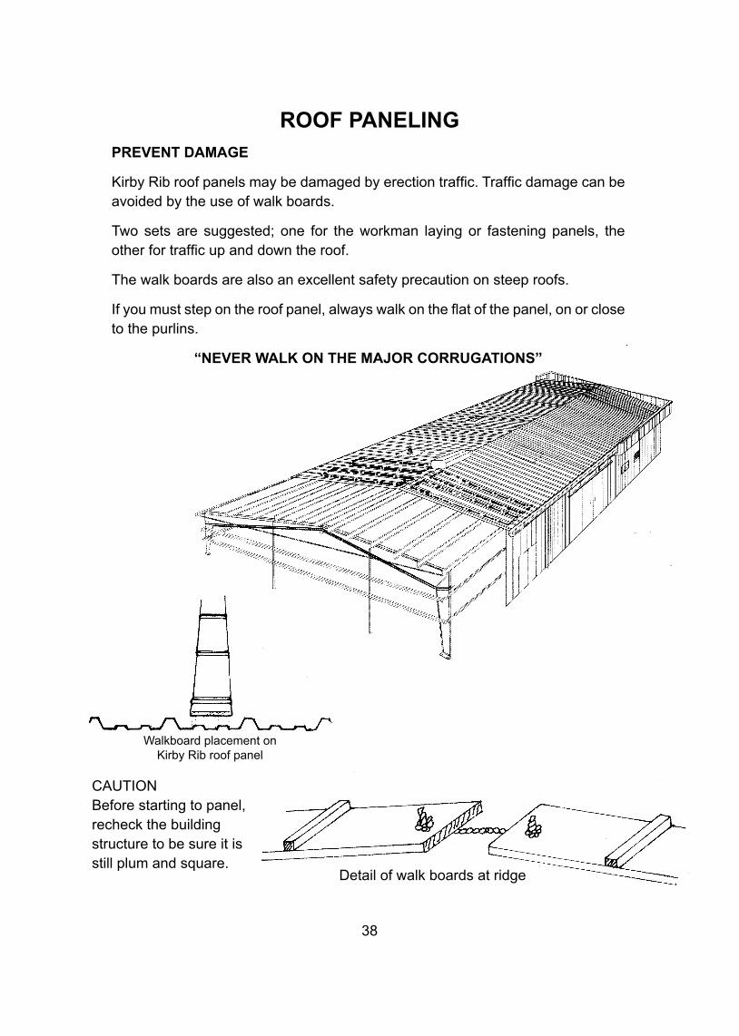
PREVENT DAMAGE
Kirby Rib roof panels may be damaged by erection traffic. Traffic damage can be avoided by the use of walk boards.
Two sets are suggested; one for the workman laying or fastening panels, the other for traffic up and down the roof.
The walk boards are also an excellent safety precaution on steep roofs.
If you must step on the roof panel, always walk on the flat of the panel, on or close to the purlins.
“NEVER WALK ON THE MAJOR CORRUGATIONS”
CAUTIONBefore starting to panel, recheck the building structure to be sure it is still plum and square.
Walkboard placement onKirby Rib roof panel
Detail of walk boards at ridge
39
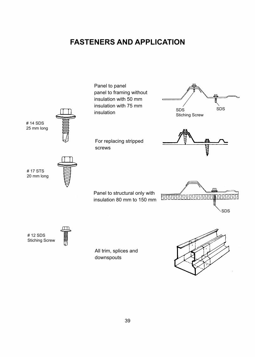
FASTENERS AND APPLICATION
For replacing stripped screws
All trim, splices anddownspouts
# 14 SDS25 mm long
# 17 STS20 mm long
# 12 SDSStiching Screw
Panel to panelpanel to framing without insulation with 50 mm insulation with 75 mm insulation SDS
Stiching Screw
SDS
Panel to structural only with insulation 80 mm to 150 mm
SDS
SIDEWALL AND ENDWALL PANEL INSTALLATION
40
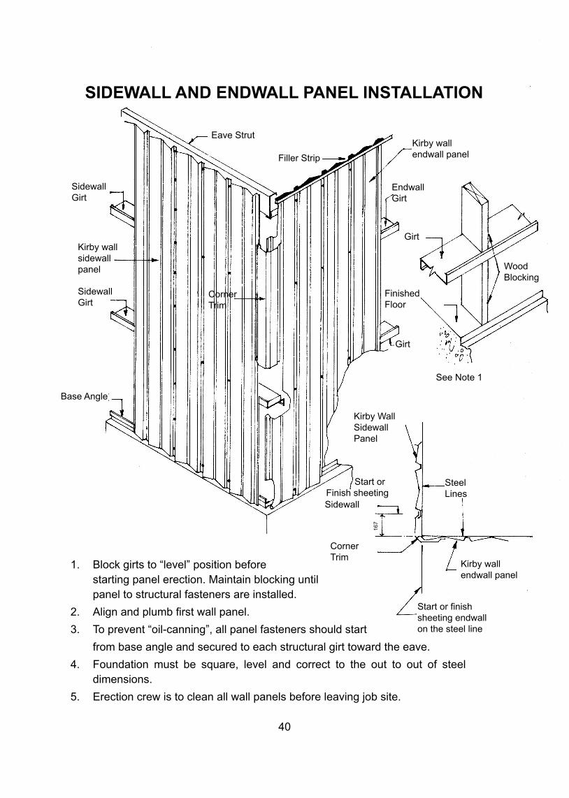
1. Block girts to “level” position before starting panel erection. Maintain blocking until panel to structural fasteners are installed.
2. Align and plumb first wall panel.
3. To prevent “oil-canning”, all panel fasteners should start
from base angle and secured to each structural girt toward the eave.
4. Foundation must be square, level and correct to the out to out of steel dimensions.
5. Erection crew is to clean all wall panels before leaving job site.
SidewallGirt
Kirby wallsidewallpanel
SidewallGirt
Eave Strut
Filler Strip
Kirby wallendwall panel
EndwallGirt
Girt
Wood Blocking
FinishedFloor
Girt
CornerTrim
Base Angle
See Note 1
Kirby WallSidewallPanel
SteelLines
Sidewall
Start orFinish sheeting
Kirby wallendwall panel
Start or finishsheeting endwallon the steel line
CornerTrim
167
41
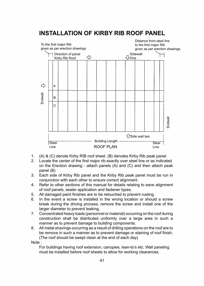
INSTALLATION OF KIRBY RIB ROOF PANEL
1. (A) & (C) denote Kirby RIB roof sheet. (B) denotes Kirby Rib peak panel.2. Locate the center of the first major rib exactly over steel line or as indicated on the Erection drawing - attach panels (A) and (C) and then attach peak panel (B)3. Each side of Kirby Rib panel and the Kirby Rib peak panel must be run in conjunction with each other to ensure correct alignment.4. Refer to other sections of this manual for details relating to eave alignment of roof panels, sealer application and fastener types.5. All damaged paint finishes are to be retouched to prevent rusting.6. In the event a screw is installed in the wrong location or should a screw break during the driving process, remove the screw and install one of the larger diameter to prevent leaking.7. Concentrated heavy loads (personnel or material) occurring on the roof during construction shall be distributed uniformly over a large area in such a manner as to prevent damage to building components.8. All metal shavings occurring as a result of drilling operations on the roof are to be remove in such a manner as to prevent damage or staining of roof finish. (The roof should be swept clean at the end of each day)Note : For buildings having roof extension, canopies, lean-to’s etc. Wall paneling must be installed before roof sheets to allow for working clearances.
To the first major Ribgiven as per erection drawings
Distance from steel lineto the first major Ribgiven as per erection drawings
Direction of panelKirby Rib Roof
SidewallOne
a
B
C
SteelLine
SteelLine
Building Length
Side wall two
End
wal
l
End
wal
l
ROOF PLAN
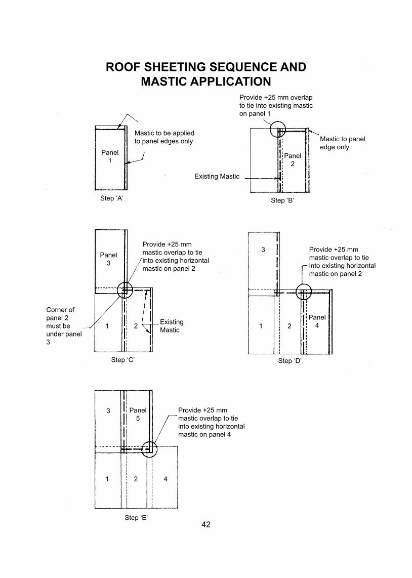
ROOF SHEETING SEQUENCE ANDMASTIC APPLICATION
42
Provide +25 mm overlap to tie into existing mastic on panel 1
Mastic to paneledge only
Mastic to be applied to panel edges only
Existing Mastic
Panel 1
Step ‘A’ Step ‘B’
Panel 3
Panel 2
Provide +25 mm mastic overlap to tie into existing horizontal mastic on panel 2
Provide +25 mm mastic overlap to tie into existing horizontal mastic on panel 2
3
1 2Panel
4
Corner of panel 2 must be under panel 3
ExistingMastic
Step ‘D’Step ‘C’
Provide +25 mm mastic overlap to tie into existing horizontal mastic on panel 4
Step ‘E’
1 2
1 2 4
Panel 5
3
43
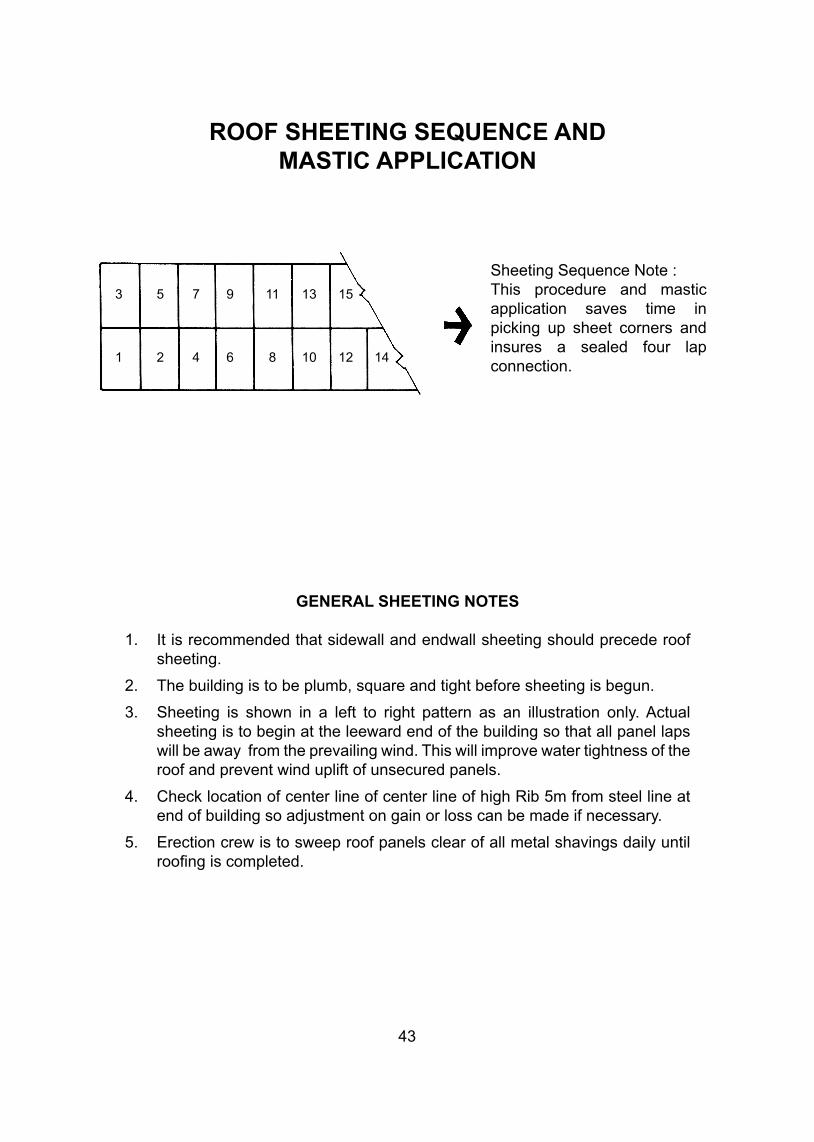
ROOF SHEETING SEQUENCE ANDMASTIC APPLICATION
GENERAL SHEETING NOTES
1. It is recommended that sidewall and endwall sheeting should precede roof sheeting.
2. The building is to be plumb, square and tight before sheeting is begun.
3. Sheeting is shown in a left to right pattern as an illustration only. Actual sheeting is to begin at the leeward end of the building so that all panel laps will be away from the prevailing wind. This will improve water tightness of the roof and prevent wind uplift of unsecured panels.
4. Check location of center line of center line of high Rib 5m from steel line at end of building so adjustment on gain or loss can be made if necessary.
5. Erection crew is to sweep roof panels clear of all metal shavings daily until roofing is completed.
Sheeting Sequence Note :This procedure and mastic application saves time in picking up sheet corners and insures a sealed four lap connection.
3 5 7 9 11 13 15
1 2 4 6 8 10 12 14
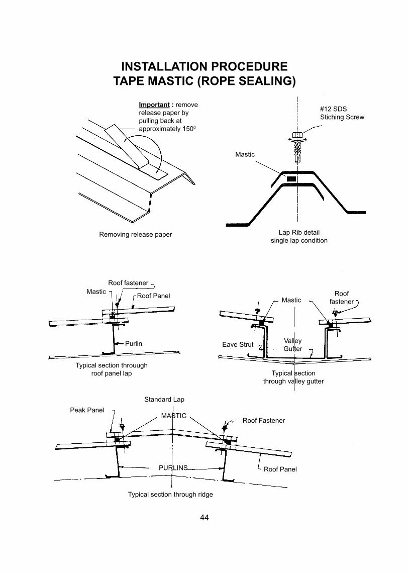
INSTALLATION PROCEDURETAPE MASTIC (ROPE SEALING)
44
Important : remove release paper by pulling back atapproximately 1500
Removing release paper
Roof fastener
Roof PanelMastic
Purlin
MasticRoof
fastener
Eave StrutValleyGutter
Typical section through valley gutter
Typical section throuugh roof panel lap
Standard Lap
Roof Fastener
Peak PanelMASTIC
Roof PanelPURLINS
Typical section through ridge
#12 SDSStiching Screw
Mastic
Lap Rib detail single lap condition
45
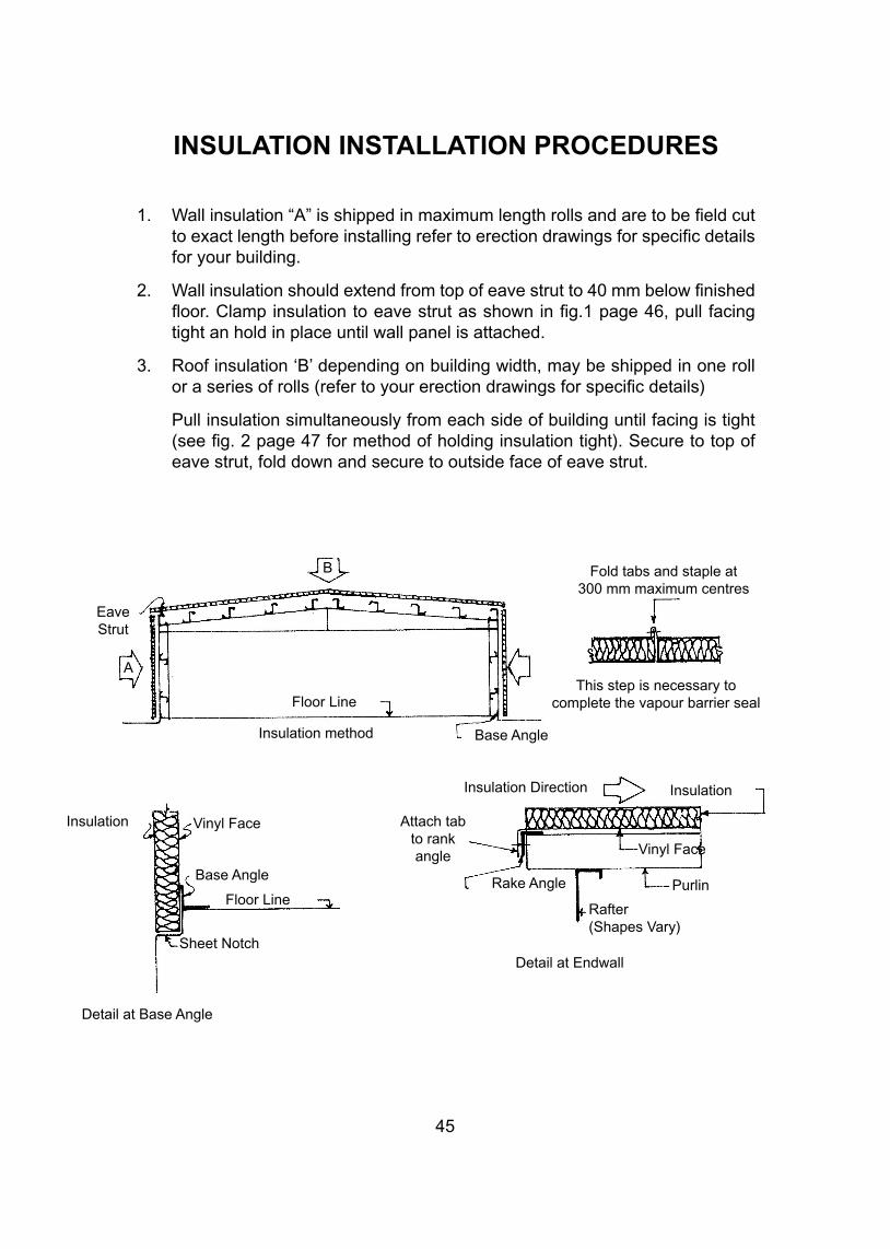
INSULATION INSTALLATION PROCEDURES
1. Wall insulation “A” is shipped in maximum length rolls and are to be field cut to exact length before installing refer to erection drawings for specific details for your building.
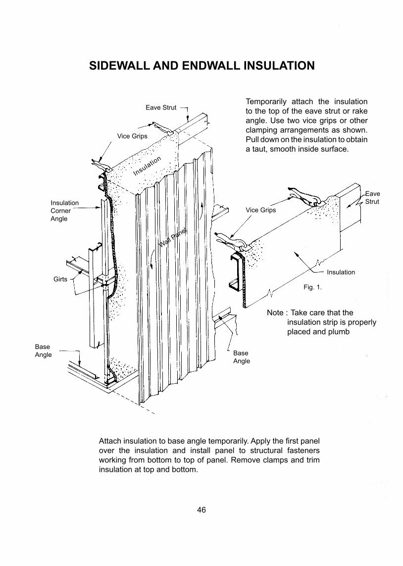
2. Wall insulation should extend from top of eave strut to 40 mm below finished floor. Clamp insulation to eave strut as shown in fig.1 page 46, pull facing tight an hold in place until wall panel is attached.
3. Roof insulation ‘B’ depending on building width, may be shipped in one roll or a series of rolls (refer to your erection drawings for specific details)
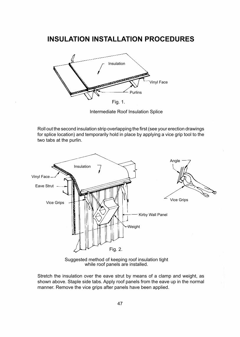
Pull insulation simultaneously from each side of building until facing is tight (see fig. 2 page 47 for method of holding insulation tight). Secure to top of eave strut, fold down and secure to outside face of eave strut.
Fold tabs and staple at300 mm maximum centres
This step is necessary tocomplete the vapour barrier sealFloor Line
B
EaveStrut
Insulation method Base Angle
Insulation Vinyl Face
Base Angle
Floor Line
Insulation Direction Insulation
Attach tabto rankangle Vinyl Face
PurlinRake Angle
Sheet Notch
Detail at Base Angle
Detail at Endwall
Rafter(Shapes Vary)
A
SIDEWALL AND ENDWALL INSULATION
46
Temporarily attach the insulation to the top of the eave strut or rake angle. Use two vice grips or other clamping arrangements as shown. Pull down on the insulation to obtain a taut, smooth inside surface.
Attach insulation to base angle temporarily. Apply the first panel over the insulation and install panel to structural fasteners working from bottom to top of panel. Remove clamps and trim insulation at top and bottom.
Eave Strut
Vice Grips
InsulationCornerAngle
Insulation
Girts
BaseAngle Base
Angle
Note : Take care that the insulation strip is properly
placed and plumb
Vice Grips
EaveStrut
Insulation
Fig. 1.
Wall Panel
47
INSULATION INSTALLATION PROCEDURES
Roll out the second insulation strip overlapping the first (see your erection drawings for splice location) and temporarily hold in place by applying a vice grip tool to the two tabs at the purlin.
Stretch the insulation over the eave strut by means of a clamp and weight, as shown above. Staple side tabs. Apply roof panels from the eave up in the normal manner. Remove the vice grips after panels have been applied.
Insulation
Vinyl Face
Purlins
Fig. 1.
Intermediate Roof Insulation Splice
Insulation
Angle
Vinyl Face
Eave Strut
Vice GripsVice Grips
Kirby Wall Panel
Weight
Suggested method of keeping roof insulation tightwhile roof panels are installed.
Fig. 2.
CLOSURE STRIPS AND APPLICATIONS
48
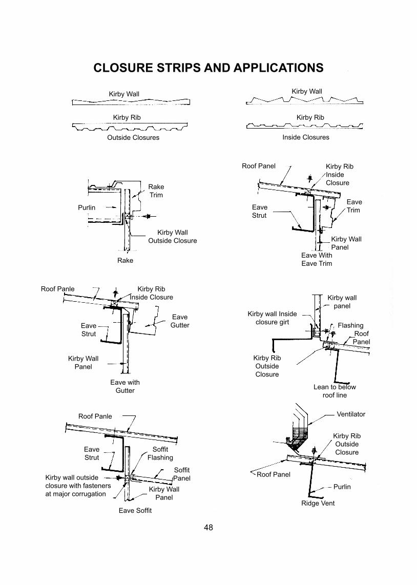
Kirby Wall Kirby Wall
Kirby Rib Kirby Rib
Outside Closures Inside Closures
Roof Panel Kirby RibInsideClosure
EaveStrut
EaveTrim
Kirby Wall Panel
Eave With Eave Trim
Kirby wall Insideclosure girt
Kirby RibOutsideClosure
Kirby wall panel
FlashingRoofPanel
Lean to below roof line
Ventilator
Kirby RibOutsideClosure
Roof Panel
Purlin
Ridge Vent
Roof Panle
SoffitFlashing
SoffitPanel
Kirby Wall Panel
Eave Soffit
Kirby wall outside closure with fasteners at major corrugation
EaveStrut
Eave withGutter
Kirby WallPanel
Eave Strut
Eave Gutter
Kirby RibInside Closure
Roof Panle
Rake
Kirby WallOutside Closure
RakeTrim
Purlin
Roof Panel
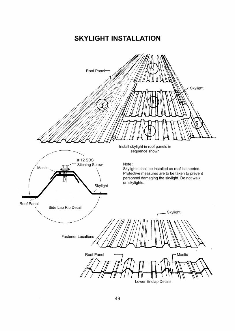
Skylight
Install skylight in roof panels in sequence shown
Note :Skylights shall be installed as roof is sheeted. Protective measures are to be taken to prevent personnel damaging the skylight. Do not walk on skylights.
Skylight
Mastic
# 12 SDSStiching Screw
Skylight
Roof PanelSide Lap Rib Detail
Fastener Locations
Roof Panel Mastic
Lower Endlap Details
49
SKYLIGHT INSTALLATION
50
Appendix ‘1’
MATERIAL CLAIMS STANDARD POLICY
I. General (A) Definition
A claim is defined as any request for the replacement of materials related to any job or straight sale already shipped where there is no charge to the customer.
(B) Type of Claim
The majority of claims fall within the following categories :
Category 1 - Items not received
A. Any material shown on the shipper and not received on site due to :
(I) Lost during transportation (II) Back ordered (material not available on the shipping date)
B. Any items ordered but not included in the shipper and accordingly not received on site.
Category 2 - Damaged Items
Any material received on site not in good condition. Category 3 - Incorrectly fabricated items
Any material not fabricated in a manner suitable for installation in accordance with KBSK’s standard product manual and/or construction drawings.
Category 4 - Design Errors
Any material manufactured, shipped and found unable to provide the function originally specified in the work order.
Category 5 - Incorrect Quantities Received
Items received in full according to quantities shown on the shipper but found incorrect during construction. There could be surplus or shortage in any item due to an error in preparing the shipper.
Category 6 - Buyouts Claims
This type is limited to the bought-out items. Shipped directly to
51
the site (not via Kuwait) without issuing a shipper covering this item from Kuwait. The claim could be any of the previous four categories.
C. Claims and insurance Appendix 1 - which defines : (I) KBSK’s legal responsibilities (II) KBSK’s definition of shipping terms (III) KBSK’s commercial responsibilities assumed for and on behalf of the customer (CIF Shipments only). Is considered as complimentary part of our policy and procedures. Cost of replacing items lost or damaged during transportation including freight will be paid. Eventually, by the insurance company or by customer (if the shipment was not insured) and therefore, requests for such materials cannot be defined as claims and will be treated as an order or straight sale.
II. PROCEDURES (1) Effective January 5th, 1980 sales managers and technical representatives shall receive copies from shipping report with each shipment that goes to their district (attachment 1). This report which will state the back ordered items and expected time of shipping it, eliminates category (I) A (II) as intercompany claim i.e. from sales office to H.Q. customer should be informed in such cases with all details.
(2) CLAIMS ACCEPTANCE Sales offices should not accept any claim unless : (A) Submitted in writing from the customer to the appropriate sales office. (B) Submitted within the following periods : (I) Items not received and/or damaged (Cat 1&2) :
- UNPACKED ITEMS 5 Days from date of arrival to the job site - PACKED ITEMS 3 Days from date of arrival to the job site. (II) Mis-fabricated items and/or incorrect quantities (cat. 3,4&5) any time during erection with a maximum of one year from date of arrival to site.(3) All accepted claims must be reviewed by the sales manager and district technical representatives before forwarding it to the H.Q.(4) All claims must be relayed to H.Q. by telex or in writing to the attention of technical service manager stating the following : (1) Date (2) Sales manager or tech rep initiating claim is inserted.
52
(3) the job number or s/s number is listed. (4) The nature of the claim is described. (5) The action you require. (6) Material required, quantity and part number. (7) Be sure to sign the request. (8) List the name of the sales manager and general sales manager receiving copies.

Kirby Building Systems - KuwaitP.O. Box 23933 Safat, 13100
Tel. : (965) 326 2800 Fax : (965) 326 1793 / 8E-mail : [email protected]
www.kirbysteelkuwait.com