ERDC TN DOER-R6 (December 2004) Liner design … · Liner Design Guidance for Confined Disposal...
25
1 ERDC TN-DOER-R6 December 2004 Liner Design Guidance for Confined Disposal Facility Leachate Control PURPOSE: This technical note provides design guidance for liners used to reduce the release of contaminants from confined disposal facilities (CDFs) containing contaminated dredged materials. Design requirements, geotechnical considerations, material selection, required thickness, construction, quality control, and monitoring are included. References to detailed design procedures are also given. This technical note is intended for use by USACE personnel and federal and state regulatory agency personnel, as well as dredging permit applicants and others. BACKGROUND: A CDF is an engineered structure designed to provide the required storage volume for dredged material and to meet the required suspended solids concentration in effluent released from the facility. Procedures for design of CDFs for storage volume and for suspended solids retention are provided in Engineer Manual 1110-2-5027 (U.S. Army Corps of Engineers (USACE) 1987). A CDF may be constructed as an upland site, as a nearshore site with one or more sides exposed to the water, or as an island containment area. The joint USACE and U.S. Environmental Protection Agency (USEPA) document “Evaluating Environmental Effects of Dredged Material Management Alternatives—A Technical Framework” (USEPA/USACE 2004) provides guidance for selecting an appropriate dredged material disposal alternative. “Evaluation of Dredged Material Proposed for Disposal at Island, Nearshore, or Upland Confined Disposal Facilities – Testing Manual” (USACE 2003) further provides procedures for identifying contaminant loss pathways (Figure 1) requiring control measures necessary for any disposal alternative. Leachate is one of the pathways shown in Figure 1. LEACHATE PATHWAY: Leachate is a liquid generated by movement of water through contaminated materials. It can be produced by several potential sources: gravity drainage of the original pore water and ponded water, inflow of groundwater, and infiltration of rainwater and snowmelt. Leachate generation and transport in a CDF thus depend on many site-specific and sediment-specific factors. Immediately after dredging and disposal, dredged material is saturated (all voids are filled with water). As evaporation and seepage remove water from the voids, the amount of water stored and available for gravity drainage decreases. Since contaminants in dredged material are primarily adsorbed to sediment particles, leaching by percolating site water from a CDF situated above the groundwater table is the primary mechanism by which contaminant migration to groundwater takes place. If the site is situated so that groundwater will flow through the material (typically, a nearshore CDF), percolating groundwater flow may be the primary source of water through the material. If the CDF is a nearshore or island facility, surface water may also be in contact with the dredged material as a result of fluctuating water levels and may transport contaminants from the CDF in a process termed tidal or wave flushing. This technical note focuses on upland CDFs. DESIGN CONSIDERATIONS FOR LINERS: Liner systems function to minimize contaminant release into the environment by controlling leachate pathways. Liners not only serve to physically isolate the sediments from lateral dikes and foundation materials, but they also function to reduce contaminant migration by employing low-permeability materials to retard the passage of water that may contain contaminants. The overall performance of the liner system is evaluated by monitoring whether or not the liner meets specific performance objectives, including its ability to meet groundwater contaminant standards at designated points of compliance.
Transcript of ERDC TN DOER-R6 (December 2004) Liner design … · Liner Design Guidance for Confined Disposal...

1
ERDC TN-DOER-R6 December 2004
Liner Design Guidance for Confined Disposal Facility Leachate Control
PURPOSE: This technical note provides design guidance for liners used to reduce the release of contaminants from confined disposal facilities (CDFs) containing contaminated dredged materials. Design requirements, geotechnical considerations, material selection, required thickness, construction, quality control, and monitoring are included. References to detailed design procedures are also given. This technical note is intended for use by USACE personnel and federal and state regulatory agency personnel, as well as dredging permit applicants and others. BACKGROUND: A CDF is an engineered structure designed to provide the required storage volume for dredged material and to meet the required suspended solids concentration in effluent released from the facility. Procedures for design of CDFs for storage volume and for suspended solids retention are provided in Engineer Manual 1110-2-5027 (U.S. Army Corps of Engineers (USACE) 1987). A CDF may be constructed as an upland site, as a nearshore site with one or more sides exposed to the water, or as an island containment area. The joint USACE and U.S. Environmental Protection Agency (USEPA) document “Evaluating Environmental Effects of Dredged Material Management Alternatives—A Technical Framework” (USEPA/USACE 2004) provides guidance for selecting an appropriate dredged material disposal alternative. “Evaluation of Dredged Material Proposed for Disposal at Island, Nearshore, or Upland Confined Disposal Facilities – Testing Manual” (USACE 2003) further provides procedures for identifying contaminant loss pathways (Figure 1) requiring control measures necessary for any disposal alternative. Leachate is one of the pathways shown in Figure 1. LEACHATE PATHWAY: Leachate is a liquid generated by movement of water through contaminated materials. It can be produced by several potential sources: gravity drainage of the original pore water and ponded water, inflow of groundwater, and infiltration of rainwater and snowmelt. Leachate generation and transport in a CDF thus depend on many site-specific and sediment-specific factors. Immediately after dredging and disposal, dredged material is saturated (all voids are filled with water). As evaporation and seepage remove water from the voids, the amount of water stored and available for gravity drainage decreases. Since contaminants in dredged material are primarily adsorbed to sediment particles, leaching by percolating site water from a CDF situated above the groundwater table is the primary mechanism by which contaminant migration to groundwater takes place. If the site is situated so that groundwater will flow through the material (typically, a nearshore CDF), percolating groundwater flow may be the primary source of water through the material. If the CDF is a nearshore or island facility, surface water may also be in contact with the dredged material as a result of fluctuating water levels and may transport contaminants from the CDF in a process termed tidal or wave flushing. This technical note focuses on upland CDFs. DESIGN CONSIDERATIONS FOR LINERS: Liner systems function to minimize contaminant release into the environment by controlling leachate pathways. Liners not only serve to physically isolate the sediments from lateral dikes and foundation materials, but they also function to reduce contaminant migration by employing low-permeability materials to retard the passage of water that may contain contaminants. The overall performance of the liner system is evaluated by monitoring whether or not the liner meets specific performance objectives, including its ability to meet groundwater contaminant standards at designated points of compliance.

ERDC TN-DOER-R6 December 2004
2
(a)
(b)
Figure 1. Potential contaminant loss pathways for CDFs (a) without, and (b) with leachate control system

ERDC TN-DOER-R6 December 2004
3
Liner design incorporates both material selection (composition) and thickness (dimension) analyses. The design must also take into consideration the type of contaminant present (material resistance), properties of the environment (vicinity of groundwater table, water chemistry, location of surface water bodies, quality and potential use of groundwater as a potable water source), climate (desiccation and freeze-thaw effects), available materials (geotechnical qualities, relative permeabilities), equipment and placement techniques, regulatory setting (mandated maximum level of loss), and resources available (funding). The composition of liners for CDFs might typically consist of a compacted subsoil layer overlain by one or more layers of low-permeability soil or clean dredged material, and in some instances, modified soils and modified clean dredged materials, compacted clay liners, or geosynthetics such as geomembranes or geosynthetic clay liners. Depending on the physical and chemical characteristics of the contaminant, the permeability of the compacted subsoil layer may be sufficiently low to allow its use as the sole liner component. It should be noted that design criteria for municipal and hazardous waste landfills provide specific recommendations for liner material and thickness requirements; however, CDFs are not regulated under the same authority as these systems. Section 404 of the Clean Water Act of 1972, as amended, and the National Environmental Policy Act (NEPA) of 1969, as amended, do not specify design criteria for CDFs and do not require specific materials or thicknesses for liners. Rather, the primary consideration is reduction in hydraulic conductivity through the CDF liner system to meet groundwater standards at the point of compliance. Figure 2 illustrates a cross section of a CDF, further broken down into cross sections of example CDF bottom liner systems. A number of different liner combinations are possible, ranging in approximate increasing order of complexity and expense: (a) compacted subsoil; followed by any combination of one or more layers of: (b) compacted soil lifts; (c) uncontaminated compacted fine-grained dredged material; (d) compacted modified soils/dredged material; (e) compacted clay liner material; (f) geomembrane; (g) geosynthetic clay liner; (h) compacted clay liner and geomembrane; (i) pelletized materials; and (j) composite liner systems consisting of compacted clay liner and geomembrane and leachate collection system. Each liner system offers particular advantages and disadvantages. The following sections provide an overview of the principle of design, applicable literature for design guidance, and specific procedures for CDFs when design varies from published guidance. The flowchart depicted in Figure 3 illustrates the major design requirements for implementation of containment features for liners and the sequence in which the design requirements should be considered. As mentioned previously, there is a strong interdependence among all components of design for a CDF project. For example, the initial consideration of the CDF location and extent of contamination within the sediments to be dredged greatly influence all subsequent design elements. Each step in the design process must be clearly identified and documented before a decision can be made to proceed to final design activities. This will also assist in ensuring that unnecessary data collection and evaluations can be avoided. If project data and sediment characteristics suggest that a CDF is necessary, and an upland site has been selected, then the following design sequence should be followed. Detailed descriptions of liner material selection criteria and thickness requirements are provided in subsequent sections. Step 1 - Select Liner System. “Leachate Screening Considerations,” ERDC TN-DOER-C16 (Schroeder 2000), provides a leachate screening protocol to evaluate the acceptability of confined disposal of dredged material. If applicable guidelines or discharge standards for contaminant loss are predicted to be exceeded by the CDF design under consideration, additional contaminant control measures must be considered to reduce contaminant loss to acceptable levels. Possible leachate control measures include (see Figures 1 and 2):

ERDC TN-DOER-R6 December 2004
4
Figure 2. Example CDF liner systems

ERDC TN-DOER-R6 December 2004
5
1. Reducing seepage through the CDF bottom by installing engineered liners comprised of one or more
of the following components: • Clean dredged material. • Compacted subsoil. • Modified soils. • Compacted clay. • Geomembranes. • Geosynthetic clay liner. • Composite (compacted clay plus geomembrane). • Leachate collection systems.
2. Controlling lateral seepage through the dikes by employment of:
• Slurry walls and trenches. • Sheet pile walls. • Reactive barriers.
3. Reducing infiltration of precipitation into the stored dredged material by installing covers comprised
of: • Compacted clay. • Modified soils. • Geomembranes.
Step 2 - Select and Characterize Liner Materials. The liner materials used in a project should be carefully selected. However, for economic reasons, a liner material comprised of clean dredged sediment is preferred and is usually sufficient to reduce contaminant fluxes to acceptable levels. Previous studies (e.g., ASCE (1997)) have shown that both fine-grained materials and sandy clays can be effective liner materials. If there are instances that dredged material does not possess adequate flux retardation properties, or regulatory authorities require otherwise, other liner materials may be employed, including compacted clay liners and composite liner systems consisting of clay coupled with geosynthetics (e.g., geomembranes). Step 3 - Select Equipment and Placement Techniques for Liner Materials and Contaminated Sediments. The major design requirement in the selection of equipment and the placement techniques for liner materials is the need for controlled, accurate placement and ensuring the necessary density and rate of application of liner material. In general, the liner material should be placed so that it accumulates in a layer of adequate thickness and density, uniformly covering the prepared subbase of the CDF. Placement of liner material at equal or greater density than the subbase material or use of placement methods to spread thin layers to gradually build up the liner thickness usually meets this requirement. Scheduling of liner construction must also consider both exposure of the liner material to the environment and engineering and operational constraints. Various equipment types and placement techniques have been used for placement of contaminated sediment. The use of equipment or placement rates that might result in the contaminated material displacing or mixing with the previously placed liner material must be avoided. Placement of contaminated material at equal or lesser density than the liner material or use of placement methods to spread thin layers to gradually build up the contaminant thickness usually meets this requirement.

ERDC TN-DOER-R6 December 2004
6
Figure 3. Design sequence for CDF containment features

ERDC TN-DOER-R6 December 2004
7
Step 4 - Evaluate Compatibility of Site, Materials, and Equipment. At this point in the design, the contaminated material has been characterized; a site has been identified and characterized; liner and cover materials have been selected and characterized; equipment and placement techniques have been selected for both materials; and positioning needs have been addressed. These essential components of the design (Blocks 2, 3, 4, 5, 6, and 7 in Figure 3) must now be examined as a whole, with compatibility in mind, to evaluate the efficacy of liner and cover placement for the sediments, site conditions, equipment availability and capabilities under consideration, and cost. The primary concern with compatibility relates to contaminated material and the ability of the subbase to support the liner, dredged material, and surface cover, considering the material characteristics and dredging and placement techniques. Guidance on the compatibility of various dredging and placement techniques for differing material types has been developed based on field experience and knowledge of the resulting physical stability of the materials. If the various site, sediment, and selected equipment components are compatible, additional and more detailed design requirements can be addressed. If there is a lack of compatibility at this point, a different CDF site, a different liner or cover material, or different dredging and placement equipment and techniques must be considered. Specific attention should also be given to chemical compatibility of the liner materials with the leachate. Chemical degradation of liner systems can result from interactions of the contaminants and/or the water in the leachate with the liner system, potentially leading to defects in the liner and increased leakage rates for leachate transport. For example, a leachate possessing a highly acidic pH can potentially dissolve metal species normally associated with the clay structure. This leaching of the clay matrix can cause increased formation of void spaces in the soil matrix, leading to increased hydraulic conductivity. Further, a study by Anderson (1982) demonstrated that clay can be more permeable to concentrated organic liquids than to pure water. Special consideration must also be given to employment of bentonite-based clay materials as liners in the presence of saltwater environments or where the leachate may contain large concentrations of salt, since the presence of salt has been shown to increase the hydraulic conductivity of bentonite clays (Petrov et al. 1997, Theriault and Mitchell 1997, Martin et al. 2000). Chemical degradation effects should be evaluated with falling head permeameters containing at least two to three samples of soils compacted in the lower portion of the acceptable zone for dry unit weight and moisture content (Qian 1995). The permeant should reflect the chemical characteristics of the leachate expected from water infiltrating through contaminated sediments. Compatibility tests for synthetic liner materials are provided in EPA Method 9090A (USEPA 1992b), while ASTM D6141-97 (ASTM 1997) provides guidance for evaluation of clay portions of geosynthetic clay liners. Step 5 - Determine Liner System (Leachate Control and Cover) Design. The liner must be designed to adequately isolate the contaminated material from the environment and achieve the intended liner functions. Determination of the required liner thickness is dependent on the physical and chemical properties of the contaminated sediments and liner materials, and it includes the liner thickness required for contaminant isolation (physical isolation plus any thickness needed for control of contaminant flux), plus that required for consolidation. The potential for consolidation and the resultant expulsion of pore water from the contaminated sediment must also be evaluated. Since the potential for liner consolidation also depends on the total liner thickness, some iterative calculations may be required. The HELPQ module (Hydrologic Evaluation of Leachate Production and Quality) (Aziz and Schroeder 1999)) of the Automated Dredging and Disposal Alternatives Management System (ADDAMS (Schroeder and Palermo 1995)) can be employed to assist the designer in determining the appropriate thickness of liner components for contaminant adsorption. One of the most important design parameters influencing liner material selection is hydraulic conductivity. Soil and dredged material liners should provide a field hydraulic conductivity of 1x10⁻⁸ to

ERDC TN-DOER-R6 December 2004
8
1x10⁻⁵ cm/sec or less when compacted. Additional reductions in hydraulic conductivity may be realized through modification of clean dredged material with additives, use of clay layers, or employment of geosynthetic materials and composite liner systems. Liners and their underlying soils must also possess sufficient strength after compaction to support themselves and the overlying materials without failure. Other design parameters influencing the selection of liner materials include: (a) potential for desiccation (e.g. Hawkins and Horton 1965, Boynton and Daniel 1985, Kleppe and Olson 1985, Montgomery and Parsons 1989, Daniel and Wu 1993); (b) resistance to freeze-thaw action (e.g., Benson and Othman 1993); (c) resistance to chemical degradation (USEPA 1985, 1986a, 1986b, 1986c, 1991a, 1991b); and (d) ability to perform without cracking during settlement (Qian 1995). CDFs should also utilize liner materials that provide the minimal cost liner system that functions to meet all design requirements during operation and post-closure. Consideration should also be given to the time required for specific liner system design and installation. Step 6 - Evaluate Site Geometry, Stability, Erosion, and Consolidation. Consolidation of liner materials following placement of contaminated material needs to be examined for its effect on permeability and flux of contaminants through the liner system. Typically, consolidation of liner systems results in reduced permeability and consequent reduction in contaminant flux. Consolidation of contaminated material also needs to be examined for its effect on the volume occupied within CDF sites and potential for impact on cover integrity and stability. In general, consolidation of the contaminated dredged material will result in more stable conditions. If the potential for consolidation of the liner, contaminated material, or cover is unacceptable, an alternative site, alternative liner, or alternative placement techniques can be considered. Step 7 - Evaluate Long-Term Performance of Liner System. The long-term performance of a CDF liner system includes its inherent ability to maintain its design effectiveness throughout the design life of the facility. Emphasis must be placed during the design process on the selection of materials and methods that will tend to maintain design characteristics for extended periods of time. Specific emphasis must be placed on compatibility of liner and cover systems with the contaminated sediment. Case studies of CDF projects requiring control measures, including conclusions drawn from field monitoring efforts, are described in “Confined Disposal Facility (CDF) Containment Features: A Summary of Field Experience,” ERDC TN-DOER-C18 (Palermo and Averett 2000). Step 8 - Develop Design Specifications. Following evaluation of the long-term performance of the proposed containment system, detailed design specifications should be written to ensure that construction of the CDF containment system meets specific performance criteria at minimum cost. Table 1 summarizes the types of information that may be used to demonstrate that the performance standard for a CDF liner system is met.
LINER MATERIALS AND COMPONENTS: Since contaminants normally associated with dredged material tend to remain bound to sediment particles, confined disposal of dredged material usually does not require the employment of highly engineered liner system components. The level of contamination of the dredged material, local availability of low-permeability construction materials, and the potential chemical flux through these materials dictate whether additional containment measures are necessary. Potential liner system components, in order of increasing complexity, include compacted subsoil, clean dredged material, modified soil/dredged material, compacted clay liner, synthetic liners, and composite liners and leachate collection layers. Construction and installation considerations specific to CDFs are provided in the “Construction Considerations” section.

ERDC TN-DOER-R6 December 2004
9
Table 1 Information Used to Demonstrate Conformance with Performance Standards for CDF Liners Information Typical Parameters Description of Liner System Description of:
• Material type and source • Thickness • Hydraulic conductivity • Recompacting and amendment requirements • Location of borrow area and any amendments Material Testing Data Test results for: • Index tests • Hydraulic conductivity • Strength, puncture resistance, etc. • Consolidation • Shrink-swell properties • Potential for dispersion/piping of dredged material due to liquid flow
through liner Liner Compatibility Data Results of hydraulic conductivity testing of liner material with representative
leachate
Liner Thickness Demonstration that the liner system thickness is sufficient to retard liquid flow-through during operating life and post-closure period
Construction Specifications Procedures for liner installation, including: • Method of compaction • Degree of compaction; water content to be achieved • Lift thickness • Methods to alter water content • Scarification requirement between lifts • Method of amending soil or dredged material, if applicable Construction Quality Assurance Description of quality assurance program and testing procedures
Compacted Subsoil. CDFs will normally be constructed near or within water bodies in an effort to reduce dredged material transportation distance. Siting in the vicinity of water bodies further offers a potential advantage in that many candidate sites possess naturally occurring low-permeability materials due to the depositional environment of rivers, lakes, and harbors. For example, in areas dominated by sluggish streams and rivers, alluvium typically consists of clayey silt (Rahn 1986), where the reduced flow velocities restrict the bed load of the stream to the finest fractions. Similarly, during high flow rates, overbank flooding may occur, allowing for deposition of silt, silty clays, and clays in the floodplains. Oxbow lakes, formed from meander cutoffs characteristic of the lower Mississippi River Valley, often fill with fine-grained clays. Relatively thin clayey lacustrine deposits are often associated with areas of the Great Lakes, while marine clay deposits are common in many coastal areas such as Boston (Rahn 1986). Low-permeability materials that may be considered potential liner element candidates are identified in Table 2 as those possessing permeabilities of 10-6 cm/s or below. Qian (1995) notes that in most cases the hydraulic conductivity must be less than or equal to 10-7 cm/s for soil liners. In some cases (e.g., a lightly contaminated dredged material), materials possessing slightly higher hydraulic conductivities may be

ERDC TN-DOER-R6 December 2004
10
employed while maintaining sufficient control of leachate. In most situations, uncontaminated fine-grained, low-permeability material is readily available for use in liner systems. Initial excavation for dikes or for site preparation will typically remove topsoil and possibly a layer of foundation soil. The bottom of the excavation may then be compacted to an optimal density through use of a sheeps-foot roller, vibratory roller, or other type of compaction equipment. If additional soil liner thickness is required, lifts of additional soil approximately 6 in. in depth should be applied, ensuring that each lift is well connected to previous and subsequent lifts through the use of sheeps-foot rollers. It is critical that optimum water content be maintained throughout the liner construction operation. Further discussion of compactive effort and moisture content requirements for optimization of hydraulic conductivity and shear strength of soil liner systems are provided in EM 1110-1-502 (USACE 1994), EPA/625/6-88/018 (USEPA 1988a), EPA/600/2-88/052 (USEPA 1988b), 57 FR 3462 (USEPA 1992a), and in later sections of this document.
Table 2 Hydraulic Conductivities of Various Soil Liners Unified Soil Classification System (USCS) or Liner Classification Hydraulic Conductivity (cm/s) Clay 10-9 to 10-6 (Fetter 2001) Barrier Soil 10-7 (Schroeder et al. 1994) CH (Inorganic Clay of high plasticity) 6.8x10⁻⁷ (Schroeder et al. 1994) SC (Sand Clay) 7.8x10⁻⁷ (Schroeder et al. 1994) Compacted Soil (see ref. for site specifics) 10-9 to 10-7 (Giroud et al. 1997) Bentonite Mat (0.6 cm) 3x10⁻⁹ (Schroeder et al. 1994) Colloidal Clay 10-10 to 10-9 (Giroud et al. 1997)
Clean Dredged Material. An inexpensive and efficient liner material that should not be overlooked in the design of CDFs is clean dredged material. When allowed to settle and condense, fine-grained material dredged from rivers and harbors can reach permeabilities as low as 10-7 to 10-10 cm/s (Giroud et al. 1997, Schroeder et al. 1994). By most standards, this range of liner permeability is acceptable for service as hydraulic barriers. With this option, areas of the channel that contain uncontaminated material are dredged first, and the material is pumped into the CDF. Following dewatering and consolidation, clean fine-grained dredged material can form a low-permeability layer. If application of fine-grained dredged material occurs after placement and compaction of a low-permeability subsoil liner, clean fine-grained dredged material will add to the total effective thickness of the liner system. Besides possessing an enhanced hydraulic barrier following consolidation, the dredged material often contains appreciable amounts of organic carbon, which increases the sorption capacity of the liner system, further retarding the transport of hydrophobic organic contaminants through the liner system. The Primary Consolidation, Secondary Compression, and Desiccation of Dredged Fill (PSDDF) computer program (Stark 1996) provides a means to quantify consolidation and settlement of dredged material and its impact on hydraulic conductivity. Modified Soils/Dredged Material. It may be necessary to site CDFs where soils and dredged material with high hydraulic conductivity (e.g., silts or sand) are ubiquitous as the natural material. Their use as liner components is limited by their hydraulic conductivity. Examples of other materials that possess high hydraulic conductivities are provided in Table 3. The preferred hydraulic conductivity for barrier systems is 10-5 to 10-8 cm/s; thus, either the native soil must be modified to reduce its hydraulic conductivity to acceptable levels, a borrow (offsite) material of lower hydraulic conductivity must be brought in and installed, or more sophisticated liner systems (e.g., geomembranes) must be employed.

ERDC TN-DOER-R6 December 2004
11
Table 3 Hydraulic Conductivities of Unconsolidated Sediments (after USEPA (1994)) Material Hydraulic Conductivity (cm/s) Silt, sandy silts, clayey sands, till 10-6 to 10-4 Silty sands, fine sands 10-5 to 10-3 Well-sorted sands, glacial outwash 10-3 to 10-1 Well-sorted gravel 10-2 to 1
The relative high cost of transporting and installing borrow materials and the exceptionally high cost of more advanced liner systems suggest that modification of native soils is an economical option worth exploring. If sand is the predominant local material, it may be modified by the addition of bentonite clay. A recent study by Wareham et al. (1998) suggests that sand deposits may be modified with bentonite clay for a reduction in hydraulic conductivity of two to four orders of magnitude. Mixing a sodium-modified, calcium-magnesium bentonite with sand at a ratio of 7.5 percent bentonite clay to 92.5 percent sand, on a dry-weight basis, reduced the hydraulic conductivity to 10-7 to 10-8 cm/s. Addition of alkaline water (lime mixed with water to pH 10.1) to achieve an optimum water content of 19.3 percent (maximum dry density of 1.635 g/cm3) resulted in an optimal separation of bentonite layers, allowing bentonite to fill the void spaces within the sand and limit the void space available for water movement. Saline water may alter the ionic balance of bentonite and increase the hydraulic conductivity to 10-5 to 10-6 cm/s. Additional guidance on soil and sediment modifications for reduced hydraulic conductivity and increased shear strength is provided by Daniel and Benson (1990). Compacted Clay Liner. Compacted clay liners (CCLs) are soil liners consisting of fine-grained materials possessing hydraulic conductivities of 10-7 cm/s or less (Qian 1995). These materials are used for bottom liners as well as surface covers to reduce infiltration of precipitation, and the plate-like shape of the soil grains prevents additional leachate formation. The fineness of the particle size of clay materials provides a means for individual clay particles to fill pore spaces, thus reducing the overall hydraulic conductivity of the soil liner. In addition to the low permeability, the high specific surface area of clay will tend to increase the surface interaction between contaminants and individual particles. This adsorption and low permeability combine to increase the overall ability of the compacted clay liner to retain the contaminated material within the CDF. The clay material used in compacted clay liners may consist of kaolinite, illite, or montmorillonite. Although each type of clay may be used in low-permeability layers, preference is often given to montmorillonite. The fineness of the clay particle size, coupled with montmorillonite's ionic surface charges, provides a large specific surface area material that interacts strongly with polar water molecules. As the water molecules come into contact with the clay, the water tends to diffuse between individual clay platelets, causing the platelets to separate and swell apart (Qian 1995). It is this swelling process, coupled with the tightly-bound water between the platelets, that gives hydrated montmorillonite an extremely low permeability. General design criteria for CCLs as liners within land disposal facilities are provided in USEPA (1978, 1988a, 1988b, 1991a, 1992a) and specific guidance for CCLs within CDFs are provided in USACE (1987). Each design criterion attempts to achieve maximum reduction in hydraulic conductivity based on material selection, thickness, compactive effort, and moisture content.

ERDC TN-DOER-R6 December 2004
12
Synthetic Liners. In rare cases of highly contaminated dredged material, more rigorous methods of containment and isolation may be necessary than those offered by compacted soil and sediment liners and covers functioning alone. A potentially economical and volumetrically efficient method to reduce leachate generation and transport is the use of manufactured geosynthetic materials such as geomembranes, geonets, and geotextiles. Each of these components functions as an integral part of a geosynthetic composite liner. Geomembranes are impermeable barrier materials designed to prevent migration of leachate into or out of the CDF. Geonets function as lateral drainage layers to assist in the drainage of leachate. Geotextiles are used between geonets and soil layers or between geonets and geomembranes and function as filters to prevent clogging of geonet drainage layers. Geosynthetic materials are rarely used in CDF liner and cover design because (1) of their high cost relative to soil liner and cover systems, and (2) CDFs do not fall under the same regulatory standards as municipal and hazardous waste landfills (which require the use of geosynthetic materials (Qian 1995)). Instances when geosynthetics may be employed in CDFs include (1) a requirement by a local regulatory authority, (2) characteristics of the contaminated sediments and potential leachate dictate the use of more restrictive control measures, and (3) characteristics of the leachate pose significant chemical degradation hazards to soil and dredged material liner integrity so that a more inert material (e.g., high-density polyethylene membrane (HDPE)) must be utilized. Geomembranes. Geomembranes offer a lightweight, low-hydraulic conductivity solution to the problem of contaminant release, including, when used in covers, control of vapors such as volatile organic compounds. With hydraulic conductivities that range from 0.5x10⁻¹⁰ to 0.5x10⁻¹³ cm/s, geomembranes can greatly improve the effectiveness of leachate control systems. High-density polyethylene (HDPE) and very-low-density polyethylene (VLDPE) are two types of geomembranes that are commonly used. HDPE liners possess outstanding chemical resistance, low permeability, and exceptional durability, as evidenced by their strong track record for employment in solid waste landfill systems (USEPA 1985). VLDPE geomembranes possess an exceptional ability to withstand elongation due to differential settlement; they also possess similar resistance to chemical degradation as HDPE. Each of these liners is available in thicknesses that range from 1 mm (40 mil) to 2.5 mm (100 mil). HDPE and VLDPE liners essentially serve as impermeable barriers to leachate transport to prevent the migration of liquids and gases from the containment facility, if they are kept in good condition with no tears or punctures. General design guidance for use of geomembranes in liner systems can be found in EPA 625/4-89/022 (USEPA 1989), EPA 530/SW-91/054 (USEPA 1991a), TM 5-818-8 (Headquarters, Department of the Army (HQDA)1995), and Koerner (1994). Differences in the requirements for CDFs and municipal and hazardous waste landfills again relate to the existence of specific requirements for materials and thicknesses for landfill systems; specific design guidance for emplacement of geomembranes in CDFs does not exist. Particular areas of difference include potential for the development of increased hydraulic head on the liner system in CDFs and production of greater leachate quantity with differing leachate quality. Because of the relative imperviousness of geomembranes, particular emphasis should be placed on reduction of hydraulic head via employment of various dewatering systems. Adherence to similar material testing requirements as that specified for landfill liners will, however, generally yield appropriate material property guidance if geomembranes are selected for use in CDFs.

ERDC TN-DOER-R6 December 2004
13
Geosynthetic clay liners. Geosynthetic clay liners (GCLs) consist of a clay layer between two layers of a synthetic material, with the intention of preventing leachate from infiltrating the clay and passing through holes and tears in the synthetic liner. GCLs use a prefabricated multiple layer system to reduce the permeability of the liner and to minimize the cost and the thickness of the liner. Table 4 lists the properties of bentonite clay, which is used as the center layer for many GCLs. Bentonite clay consists of platelets that are ionically charged and thus attract polar molecules such as water (Gundle Lining Systems, Inc. 1993). The polar water molecules wedge themselves between the molecules of the clay and cause swelling to occur. This swelling effect reduces the permeability of the clay by nearly eliminating any flow paths between the platelets. When the clay is combined with the geomembrane layers, the resulting liner efficiently blocks the migration of an aqueous solution that contains contaminants. The layers of geomembranes between which the clay is sandwiched prevent desiccation as described in the previous section on compacted clay liners. Daniel and Wu (1993) compared the qualities of GCLs to those of compacted clay liners (CCLs) (Table 5) for municipal landfills. Their comparison leads one to believe that GCLs are a more viable option than CCLs, except for very short storage periods (e.g., less than five years) (Qian 1995). With the large areal extent of CDFs, however, the GCL may prove to be a significantly more expensive option compared to a CCL, which may be locally available and cost many times less to employ.
Table 5 Comparison of CCL with GCL (after Daniel and Wu (1993)) Compacted Clay Liner Geosynthetic Clay Liner Thick (0.6 ~ 1.5 m) Thin (<10 mm) Field constructed Manufactured Hard to build correctly Easy to build (unroll and place) Impossible to puncture Possible to damage and puncture Constructed with heavy equipment Light construction equipment required Often requires test pad at each site Repeated field testing not needed Site-specific data on soils needed Manufactured product; data available Large leachate-attenuation capacity Small leachate-attenuation capacity Large thickness; takes up space Little space is wasted Cost is highly variable More predictable cost Soil has low tensile strength Higher tensile strength Can desiccate and crack Cannot crack until wetted Difficult to repair Not difficult to repair Vulnerable to freeze-thaw damage Less susceptible to freeze-thaw damage Performance depends highly on quality of construction
Hydraulic properties are less sensitive to construction variabilities
Slow construction Much faster construction
Table 4 Bentonite Properties Property Value Liquid limit 500-600% Plastic limit 30-60% Hydraulic conductivity <10-9 cm/sec pH 9 Moisture content (field) 24% Moisture content (processed) 8%

ERDC TN-DOER-R6 December 2004
14
General design guidance for use of GCLs in liner systems can be found in EPA 625/4-89/022 (USEPA 1989), EPA 530/SW-91/054 (USEPA 1991a), and TM 5-818-8 (HQDA 1995). Design guidance considerations for employment of GCLs in CDFs are similar to those discussed for geomembranes. Composite Liner. Composite liners consist of a combination of geomembranes with compacted clay or geosynthetic clay liners. While each composite component possesses particular strengths, including low permeabilities, their resistance to permeation is enhanced when used in a composite manner. For example, geomembranes function best when they are used as part of a composite liner system. Leachate seepage can occur throughout the entire cross-sectional area of a single soil liner. However, employment of a geomembrane with potential defects (due to rips, tears, or improper welding of seams) only marginally improves leachate collection and the resistance to percolation, unless the geomembrane is coupled with a low-permeability underlying layer such as a compacted clay liner or fine-grained foundation soil. In this case, the pathway for leachate transport is limited to only the area provided by the original geomembrane defect (Qian 1995). Detailed procedures for design of composite liner systems for solid and hazardous waste landfills are provided in USEPA (1988a, 1988b, 1991a, 1992a). Current design specifications for landfill liners include use of double composite systems. The first (upper) composite layer acts as the primary leachate collection system underlain by the primary hydraulic barrier. The second (lower) composite layer serves as the secondary leachate collection system, and the bottom portion of the lower composite system serves as a secondary hydraulic barrier. No similar design requirement exists for CDFs; in fact, employment of a double composite liner for CDFs would likely be unnecessary and cost-prohibitive. It is more likely that CDF designs contemplating the use of engineered composite liner systems will only consider single composite liner systems. In such cases, design procedures similar to those noted in USEPA (1988a, 1992a, 1993a, 1993b) should be employed, with special regard to use of the dewatering systems described below. Leachate Collection System. Infiltration of rainwater and consolidation of dredged material within CDFs result in the production of leachate. While vertical wick drains remove water throughout a CDF, leachate collection systems (although rarely employed in CDFs) target leachate accumulated at the top of bottom liners. This leachate is then collected and transported via gravity through drainage layers to centralized locations for subsequent removal and treatment. Vertical wick drains and leachate collection systems are important for their ability to assist in reducing the accumulation of leachate overlying liner systems. Reduction of the hydraulic head results in a direct reduction in the primary driving force for contaminant movement through CDF liner systems – advective transport. General design criteria for installation of leachate collection systems in municipal solid waste and hazardous waste landfills are detailed in USEPA (1992a). Such leachate collection systems employ a highly permeable drainage layer (e.g., gravel with perforated pipe or geocomposite drain) overlying a very low-permeability compacted clay liner or geomembrane. The drainage layer is then overlain by a filter soil or synthetic geotextile to separate the contaminated dredged material from the drainage layer and to filter the leachate to prevent clogging of the drainage layer. Leachate collection systems for CDFs, if employed, will likely differ significantly from those employed in solid and hazardous waste landfills in that CDFs do not normally employ double composite liners with primary and secondary leachate collection systems. Additional differences include: • Quantity of leachate – Dredged material, depending on the method of dredging, contains between 50
and 80 percent water (USEPA 1994), which is significantly higher than the 20-percent water content typically found in solid waste in municipal and hazardous waste landfills (Tchobanoglous et al.

ERDC TN-DOER-R6 December 2004
15
1993). This increased water content results in potentially significant initial short-term quantities of leachate. However, this leachate flow will decrease greatly as the dredged material consolidates and seals the bottom of the fill.
• Quality of leachate – Leachate provided by dredged material within CDFs may contain more
suspended and colloidal materials than landfill leachate. Special consideration must be given to the operation of the leachate collection system and the selection of the system filter material overlying the drainage layer to ensure that it will not become clogged by suspended and colloidal materials contained within the leachate.
DATA REQUIREMENTS AND TESTING Soils and Dredged Material. Design of CDF soil and dredged material liners requires testing of individual soils and sediments for determination of optimum particle size, Atterberg limits, compactive efforts, moisture content and dry unit weight, hydraulic conductivity, and permeability. Data requirements and testing standards for soils and dredged materials are provided in Table 6.
Table 6 Data Requirements and Testing Standards for Soils and Dredged Material
Requirement ASTM Procedures and References Comments
Unified Soil Classification System (USCS)
ASTM D2487-00 (ASTM 2000a)
Used to classify engineering properties of soils based on particle size and organic matter content.
Atterberg Limits ASTM D4318-00 (ASTM 2000d) EM 1110-2-1906 (USACE 1970)
Provide water contents at which a fine-grained soil or sediment changes from a semisolid to a plastic solid and from a plastic solid to a semiliquid.
Compactive Effort Standard Proctor Test Modified Proctor Test Reduced Proctor Test
ASTM D698-00a (ASTM 2000g) ASTM D1557-00 (ASTM 2000h) Daniel and Benson (1990)
Ideally, optimum compactive effort should be evaluated in actual field conditions through a series of test sections. However, the cost of determining design parameters in this manner is often prohibitive (Qian 1995). Most design criteria are thus developed from laboratory tests employing methods of compaction that best match actual field compaction effort (Qian 1995). Represents an average compactive effort delivered to soils in the field. Represents maximum compactive effort delivered to soils in the field. Recognizing that the greatest hydraulic conductivities would be realized in soils and dredged material experiencing the least compactive effort, Daniel and Benson (1990) developed an altered standard Proctor procedure called a "reduced" Proctor test. In this case, only 15 drops of the hammer per lift are used instead of the standard Proctor test use of 25 drops. This reduced compactive effort is believed to represent the minimum level of compaction for a typical soil or sediment liner (Qian 1995).
(Continued)
ERDC TN-DOER-R6 December 2004
16
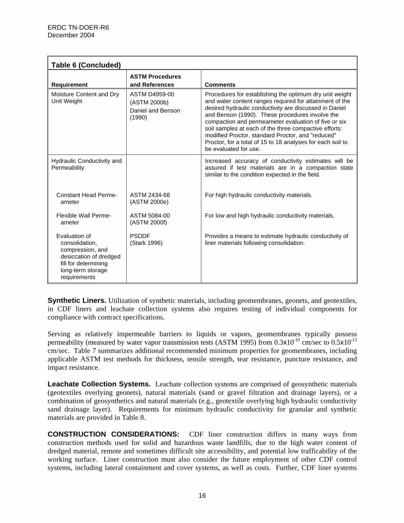
Table 6 (Concluded)
Requirement ASTM Procedures and References Comments
Moisture Content and Dry Unit Weight
ASTM D4959-00 (ASTM 2000b) Daniel and Benson (1990)
Procedures for establishing the optimum dry unit weight and water content ranges required for attainment of the desired hydraulic conductivity are discussed in Daniel and Benson (1990). These procedures involve the compaction and permeameter evaluation of five or six soil samples at each of the three compactive efforts: modified Proctor, standard Proctor, and "reduced" Proctor, for a total of 15 to 18 analyses for each soil to be evaluated for use.
Hydraulic Conductivity and Permeability Constant Head Perme-
ameter Flexible Wall Perme-
ameter Evaluation of
consolidation, compression, and desiccation of dredged fill for determining long-term storage requirements
ASTM 2434-68 (ASTM 2000e) ASTM 5084-00 (ASTM 2000f) PSDDF (Stark 1996)
Increased accuracy of conductivity estimates will be assured if test materials are in a compaction state similar to the condition expected in the field. For high hydraulic conductivity materials. For low and high hydraulic conductivity materials. Provides a means to estimate hydraulic conductivity of liner materials following consolidation.
Synthetic Liners. Utilization of synthetic materials, including geomembranes, geonets, and geotextiles, in CDF liners and leachate collection systems also requires testing of individual components for compliance with contract specifications. Serving as relatively impermeable barriers to liquids or vapors, geomembranes typically possess permeability (measured by water vapor transmission tests (ASTM 1995) from 0.3x10⁻¹⁰ cm/sec to 0.5x10⁻¹³ cm/sec. Table 7 summarizes additional recommended minimum properties for geomembranes, including applicable ASTM test methods for thickness, tensile strength, tear resistance, puncture resistance, and impact resistance. Leachate Collection Systems. Leachate collection systems are comprised of geosynthetic materials (geotextiles overlying geonets), natural materials (sand or gravel filtration and drainage layers), or a combination of geosynthetics and natural materials (e.g., geotextile overlying high hydraulic conductivity sand drainage layer). Requirements for minimum hydraulic conductivity for granular and synthetic materials are provided in Table 8. CONSTRUCTION CONSIDERATIONS: CDF liner construction differs in many ways from construction methods used for solid and hazardous waste landfills, due to the high water content of dredged material, remote and sometimes difficult site accessibility, and potential low trafficability of the working surface. Liner construction must also consider the future employment of other CDF control systems, including lateral containment and cover systems, as well as costs. Further, CDF liner systems

ERDC TN-DOER-R6 December 2004
17
may employ performance-based contracts (e.g., contractor meets hydraulic conductivity requirements of liner system) as opposed to the specification-based contracts normally required in landfill construction, which may prescribe use of specific materials with specific thicknesses. Last, superior quality assurance and quality control procedures must be maintained throughout the period of liner construction.
Table 7 Property and Test Method for Geosynthetics and Recommended Minimum Properties for General Geomembrane Installation Survivability (after Koerner (1990))
Required Degree of Survivability Geosynthetic Property and Test Method Low1 Medium2 High3 Very High4 Thickness (ASTM D1593) (ASTM 1999a)
20 mils 0.50 mm
25 mils 0.63 mm
30 mils 0.75 mm
40 mils 1.00 mm
Tensile (1.0 [in] 25 [mm]) strip) (ASTM D882) (ASTM 2002)
30 lb/in 5.2 kN/m
40 lb/in 7.0 kN/m
50 lb/in 8.7 kN/m
60 lb/in 10.5 kN/m
Tear (ASTM D1004 Die C) (ASTM 2003)
5 lb 22 N
7.3 lb 33 N
10 lb 45 N
15 lb 67 N
Puncture (ASTM D3787 mod.) (ASTM 2001)
20 lb 90 N
25 lb 110 N
30 lb 130 N
35 lb 160 N
1 Low refers to careful hand placement on very uniform well-graded subgrade with light loads of a static nature - typical of vapor barriers beneath building floor slabs.
2 Medium refers to hand or machine placement in machine-graded subgrade with medium loads - typical of canal liners.
3 High refers to hand or machine placement on machine-graded subgrade of poor texture with high loads - typical of landfill liners and covers.
4 Very High refers to hand or machine placement on machine-graded subgrade of very poor texture with high loads – typical of reservoir covers and liners for heap leach pads.
Compacted Density and Moisture Content. In order to achieve a minimum hydraulic conductivity and optimum shear strength, liners must be compacted to a maximum dry unit weight and within a specified range of water content (Qian 1995). The dry unit weight of the compacted soil is usually specified to be 95 percent of the maximum dry unit weight from standard Proctor compaction (ASTM D698-00a (ASTM 2000g) or 90 percent of the maximum dry unit weight from modified Proctor compaction (ASTM D1557-00 (ASTM 2000h)) (Herrmann and Elsbury 1987). This criterion was historically based on the desires of earthwork construction designers to achieve a maximum dry unit weight for adequate strength and limited compressibility (Qian 1995). Optimum water contents are usually 0 to 4 percent wet of standard or modified Proctor optimum because the wet-side compaction minimizes hydraulic conductivity (Lambe 1958, Boynton and Daniel 1985, Qian 1995) in the short term, though long-term conductivity may be greater after drying. Site Accessibility. CDFs may be located in rather remote and difficult-to-access areas. Although equipment for liner installation, primarily consisting of scrapers, crawler-mounted tractors, dump trucks, compactors, and cranes is relatively easy to transport on barges or constructed roads, additional mobilization effort may be required to move equipment down steep slopes or across more remote areas. Trafficability. CDF sites often possess an unstable working surface prior to construction and during operation because of high water content and the presence of low shear-strength dredged material, resulting in reductions in trafficability. These environments can be improved through application of geotextiles and granular soils to assist trafficability. FM 5-410 (HQDA 1992) provides design guidance on improving bearing strength of low shear-strength soils.

ERDC TN-DOER-R6 December 2004
18
Table 8 Data Requirements and Testing for Leachate Collection Systems
Requirement ASTM Procedures and References Comments
Granular materials USEPA 1992a Minimum hydraulic conductivity of 1x10⁻² cm/sec is stipulated for granular materials used for the drainage layer for waste piles and landfills and 1x10⁻¹ cm/sec for granular materials used in surface impoundments. Most clean, free-draining sands and gravels function adequately as drainage layers for leachate collection systems. Those soils which function best as drainage layers normally contain less than 6 percent by weight (74 microns or 0.0029 inches) passing the No. 200 sieve (U.S. Standard) and have a hydraulic conductivity greater than 10 cm/s. Soils which contain higher fractions of fines may function adequately during the initial phases of the operation, but experience has shown that these soils are more susceptible to clogging as a result of biological activity and saturation from the leachate. Gravel installed with particle sizes that are too small tend to "sift" into the waste leaving a void. Those with grain-size distributions that are too large tend to entrain and accumulate fine particulate matter that can either clog the drainage layer or the filter fabric around the layer.
Synthetic materials USEPA 1992a Synthetic materials used in drainage layers require a minimum hydraulic transmissivity of 3x10⁻⁵ m2/sec for waste piles and landfills and 3x10⁻⁴ m2/sec for synthetic drainage materials used in surface impoundments.
Geonets
ASTM D4716-00 (ASTM 2000c)
Used as lateral drainage layers in leachate collection systems, geonets serve as high-hydraulic-conductivity corridors for leachate transport.
Geotextiles Permeability Soil retention
USEPA 1992a ASTM 4751-99a (ASTM 1999b)
Soil retention and adequate permeability are required for proper function of geotextiles to filter leachate and separate soil, dredged material, and other liner materials from the drainage layers.
Costs. Liner costs are directly related to the areal size of the CDF. The larger the CDF, the greater the amount of liner materials and construction effort required. A careful study of the tradeoff between areal footprint and hydraulic efficiency to enhance suspended solids removal is required, as outlined in USACE (1987). For example, using spur dikes to increase hydraulic efficiency can reduce the areal footprint, resulting in reduced liner costs. USACE models DYECON (Hayes and Schroeder 1992a) and SETTLE (Hayes and Schroeder 1992b) are also available to assist the designer in this regard. A second factor in liner costs is the selection of liner materials. As illustrated in Table 9, qualitative costs for liner systems range from the least cost (clean dredged material) to the most expensive (composite liner system). Additional cost considerations include site accessibility (mobilization and demobilization) and labor and material costs of the geographic region.

ERDC TN-DOER-R6 December 2004
19
Table 9 Relative Cost Ranges for Select Liner Material Systems Liner System Qualitative Cost Ranges Dredged material liner $$ Soil liner $$$$ Modified soil/dredged material liner $$$$$$$$ Geomembrane liner $$$$$$$$$$$$$$$$$$$$ Geosynthetic clay liner $$$$$$$$$$$$$$$$$$$$$$ Composite liner $$$$$$$$$$$$$$$$$$$$$$$$$$$$$ Note: Each liner system includes a compacted subgrade.
Construction Contracts. CDF construction contracts are normally specification-based; although performance-based criteria may provide contractors additional incentive to furnish innovative designs that reduce costs while still meeting design requirements. Quality Assurance and Quality Control. Exercise of good construction practices, including protection of compacted lifts from desiccation and freezing, effective mixing of soil, and interlocking of previous and subsequent liner lifts, should also include provisions for active and vigilant supervision of construction activities and laboratory testing by qualified quality assurance and quality control personnel. Details on quality assurance and quality control issues for liner systems are provided in EM 1110-2-1911 (USACE 1995) for earthwork and for geosynthetic systems by government (e.g., USEPA 1986a, 1987, 1993c), and industry trade organizations and manufacturers (e.g., Waste Management of North America, Inc. (WMI) 1990, National Seal Company (NSC) 1991a, 1991b). OPERATIONAL CONSIDERATIONS: CDF operational considerations include dewatering, performance/effectiveness, reliability, and monitoring. Dewatering. CDFs differ from solid and hazardous waste landfills in that dredged material has significantly higher initial moisture content. Therefore, dredged material dewatering should be considered in liner design. Dewatering serves several purposes: (1) removal of potential leachate as the water continues to move through the contaminated dredged material, (2) facilitation of the progression of the geotechnical characteristics of the dredged material to a state of adequate strength to serve future site use (e.g., ballpark, or borrow area for high organic content soils), (3) reduction in storage volume as water is removed from pore spaces to produce space for future additional disposal, and (4) consolidation of the dredged material, which tends to reduce its hydraulic conductivity. This reduced hydraulic conductivity possesses both an advantage in reducing the overall permeability of a CDF for infiltration of precipitation with consequent leachate formation and transport and the disadvantage of reducing the rate of future dewatering. Numerous methods of dewatering exist. Surface trenching for improved drainage and use of underdrains (i.e., leachate collection systems), however, are the only technically feasible and economically justifiable dewatering techniques for dredged material containment areas. Dewatering techniques employing various surface trenching technologies, including progressive trenching, perimeter dragline trenching, and interior trenching, are summarized in EM 1110-2-5027 (USACE 1987). Surface trenching techniques possess significant advantages over underdrain systems alone in that trenches are able to access full depths of the CDF, while leachate collection systems only target water accumulated on the bottom liner. Underdrains have been successfully applied on a small scale; however, their use in large disposal areas has not been proven economical as compared with surface drainage techniques. Formation of excess leachate that

ERDC TN-DOER-R6 December 2004
20
cannot be successfully captured or controlled by a trenching system may, however, necessitate the installation of a leachate collection system for leachate control and containment. Operating the drains only after disposal and the onset of desiccation will extend the life of the underdrain and improve the overall performance. Performance/Effectiveness. Performance of liner systems relates to the ability of the liner (working as a system with the compacted subgrade, dredged material, lateral control measures, and covers) to control the movement of leachate so as to meet or exceed design requirements. The overall effectiveness of liner systems within CDFs thus encompasses an evaluation of the performance of the entire CDF system. It is likely that a number of different combinations of liner materials, lateral controls, and cover materials will provide adequate performance. The design should thus use the lowest cost combination of reliable and implementable control means that meet performance objectives. The Hydrologic Evaluation of Leachate Production and Quality (HELPQ) model (Aziz and Schroeder 1999) provides a means to assess leachate quantity and quality for various combinations of liner and cover systems. Reliability. Reliability of liner systems refers to the ability of the liner to perform as intended throughout its design life. The reliability of individual systems is a function of material manufacture, subgrade preparation, installation techniques, experience of construction personnel, projected loads, leachate compatibility, and control of desiccation. In effect, increased liner reliability implies a reduction in the probability of a liner not meeting design requirements. Technical Note DOER-R1 (USAE WES 1998) provides an overview of the risk management approach to dredged material operations. Monitoring. Monitoring landfill leachate provides a means to assess the relative reliability of liner systems. If it is determined that monitoring is required, then several methods should be considered, including installation of groundwater monitoring wells to detect potential contaminant migration in the subsurface or installation of secondary leachate collection systems to collect leachate that may pass through the liner system. However, effective monitoring is difficult to perform and can be expensive. SUMMARY: This technical note presents technical guidance for CDF liner design to enhance containment of pollutants. The guidance is summarized in the points below.
• Liner materials that isolate the contaminated material in CDFs from the environment must be
properly designed and constructed. • Liner materials must also be characterized from physical, chemical, and biological standpoints.
Physical characteristics determine the behavior during placement of the liner and long-term consolidation and stability against chemical and biological degradation.
• Selection of an appropriate site is a critical requirement for any CDF construction project. General
considerations include potential leachate pathways (bottom leakage, lateral seepage, vertical leachate movement during consolidation, surface runoff, and volatile emissions).
• Leachate screening considerations (Schroeder 2000) guide designers in selecting the best materials to
adequately control potential leachate pathways. Modeling efforts for leachate transport serve as the basis for liner design material and thickness requirements. Further, consolidation effects on permeability and overall leachate generation and movement can be modeled with the Primary Consolidation, Secondary Compression, and Desiccation of Dredged Fill (PSDDF) model (Stark 1996) and the model Hydrologic Evaluation of Leachate Production and Quality (HELPQ) model (Aziz and Schroeder 1999), respectively.
ERDC TN-DOER-R6 December 2004
21
• A number of different materials may potentially be employed as liner components. In general, clean dredged material, due to its characteristic fine-grained nature and low permeability, may often serve as a highly adequate material for liner systems.
• The cost of using clean dredged material as the primary or sole liner material is generally lower than
alternatives involving more engineered systems. The designer should consider a number of material alternatives in the initial feasibility study to ensure that the most economical, yet environmentally sound, options are selected.
POINTS OF CONTACT: For additional information, contact Dr. Paul R. Schroeder, (601-634-3709, [email protected]) or the program manager of the Dredging Operations and Environmental Research Program, Dr. Robert M. Engler, (601-634-3624, Robert.M.Engler @erdc.usace.army.mil). This technical note should be cited as follows:
LeBoeuf, E. J., Thackston, E. L., Schroeder, P. R., and Palermo, M. R. (2004). “Liner design guidance for confined disposal facility leachate control,” DOER Technical Notes Collection (ERDC TN DOER-R6), U.S. Army Engineer Research and Development Center, Vicksburg, MS. http://el.erdc.usace.army.mil/publications.cfm?Topic=TechNote&Code=doer
REFERENCES Anderson, D. (1982). “Does landfill leachate make clay liners more permeable?” Civil Engineering 52 (9): 66-69. American Society of Civil Engineers (ASCE). (1997). “Composite liners improve landfill performance,” Civil
Engineering 67 (12): 18-19. American Society for Testing and Materials (ASTM). (1995). “Standard guide for selection of test methods to
determine rate of fluid permeation through geomembranes for specific applications,” ASTM D5886-95, West Conshohocken, PA.
_______. (1997). “Standard guide for screening the clay portion of a geosynthetic clay liner (GCL) for chemical
compatibility to liquids,” ASTM D6147-97, West Conshohocken, PA. _______. (1999a). “Standard specification for nonrigid vinyl chloride plastic film and sheeting,” ASTM D1593-99,
West Conshohocken, PA. _______. (1999b). “Standard test method for determining apparent opening size of a geotextile,” ASTM D4751-
99a, West Conshohocken, PA. _______. (2000a). “Standard classification of soils for engineering purposes,” ASTM D2487-00, West
Conshohocken, PA. _______. (2000b). “Standard test method for determination of water (moisture) content of soil by direct heating,”
ASTM D4959-00, West Conshohocken, PA. _______. (2000c). “Standard test method for determining the (in-plane) flow rate per unit width and hydraulic
transmissivity of a geosynthetic using a constant head,” ASTM D4716-00, West Conshohocken, PA. _______. (2000d). “Standard test method for liquid limit, plastic limit, and plasticity index of soils,” ASTM D4318-
00, West Conshohocken, PA. _______. (2000e). “Standard test method for permeability of granular soils (constant head),” ASTM D2434-
68(2000), West Conshohocken, PA.

ERDC TN-DOER-R6 December 2004
22
American Society for Testing and Materials (ASTM). (2000f). “Standard test methods for measurement of hydraulic conductivity of saturated porous materials using a flexible wall permeameter,” ASTM D5084-00, West Conshohocken, PA.
_______. (2000g). “Standard test methods for laboratory compaction characteristics of soil using standard effort
(12,400 ft-lbf/ft3 (600 kN-m/m3)),” ASTM D698-00a, West Conshohocken, PA. _______. (2000h). “Standard test methods for laboratory compaction characteristics of soil using modified effort
(56,000 ft-lbf/ft3 (2,700 kN-m/m3)),” ASTM D1557-00, West Conshohocken, PA. _______. (2001). “Test method for bursting strength of textiles-constant-rate-of-traverse (CRT) ball burst test,”
ASTM D3787-01, West Conshohocken, PA. _______. (2002). “Standard test method for tensile properties of thin plastic sheeting,” ASTM D882-02, West
Conshohocken, PA. _______. (2003). “Standard test method for initial tear resistance of plastic film and sheeting,” ASTM D1004-
94a(2003), West Conshohocken, PA. Aziz, N. M., and Schroeder, P. R. (1999). "Documentation of the HELPQ module for ADDAMS: Hydrologic
evaluation of leachate production and quality for confined disposal facilities," Environmental Effects of Dredging Technical Notes EEDP-06-20, U.S. Army Engineer Waterways Experiment Station, Vicksburg, MS.
Benson, C. H., and Othman, M. A. (1993). “Hydraulic conductivity of compacted clay frozen and thawed in situ,”
Journal of Geotechnical Engineering, ASCE 119 (2): 276-294. Boynton, S. S., and Daniel, D. E. (1985). “Hydraulic conductivity test on compacted clay,” Journal of Geotechnical
Engineering, ASCE 111 (4): 465-478. Daniel, D. E., and Benson, C. H. (1990). “Water content-density criteria for compacted soil liners,” Journal of
Geotechnical Engineering 116 (12): 1811-1830. Daniel, D. E., and Wu, Y. (1993). “Compacted clay liners and covers for arid sites,” Journal of Geotechnical
Engineering 119 (2): 223-237. Fetter, C. W. (2001). Applied hydrogeology. Fourth Edition, Prentice-Hall, Upper Saddle River, NJ. Giroud, J. P., Badu-Tweneboah, K., and Soderman, K. L. (1997). “Comparison of leachate flow through
compacted clay liners and geosynthetic clay liners in landfill liner systems,” Geosynthetics International 4(3-4), 391-431.
Gundle Lining Systems, Inc. (1993). Gundseal products manual. Houston, TX. Hawkins, R. H., and Horton, J. H. (1965). “Bentonite as a protective cover for buried radioactive waste,” Health
Physics 13(3): 287-292. Hayes, D. F., and Schroeder, P. R. (1992a). "Documentation of the DYECON module for ADDAMS: Determining
the hydraulic retention and efficiency of confined disposal facilities," Environmental Effects of Dredging Technical Notes EEDP-06-17, U.S. Army Engineer Waterways Experiment Station, Vicksburg, MS.
Hayes, D. F., and Schroeder, P. R. (1992b). "Documentation of the SETTLE module for ADDAMS: Design of
confined disposal facilities for solids retention and initial storage," Environmental Effects of Dredging Technical Notes EEDP-06-18, U.S. Army Engineer Waterways Experiment Station, Vicksburg, MS.
Herrmann, J. G. and Elsbury, B. R. (1987). “Influence factors in soil liners construction for waste disposal
facilities,” Geotechnical Practice for Waste Disposal, ASCE, Ann Arbor, MI.

ERDC TN-DOER-R6 December 2004
23
Headquarters, Department of the Army (HQDA) (1992). “Military soils engineering,” FM 5-410, Department of the
Army, Washington, DC. _______. (1995). “Engineering use of geotextiles,” TM 5-818-8, Department of the Army, Washington, DC. Kleppe, J. H., and Olson, R. E. (1985). “Desiccation cracking of soil barriers,” Hydraulic Barriers in Soil and Rock,
ASTM 874, West Conshohocken, PA. Koerner, R. M. (1990). Designing with geosynthetics. Second Edition, Prentice-Hall, Englewood Cliffs, NJ. _______. (1994). Designing with geosynthetics. Third Edition, Prentice-Hall, Englewood Cliffs, NJ. Lambe, T. W. (1958). “The permeability of compacted fine-grained soils,” Special Technical Publication 163,
ASTM, Philadelphia, PA. Martin, M., Cuevas, J., and Leguey, S. (2000). “Diffusion of soluble salts under a temperature gradient after the
hydration of compacted bentonite,” Applied Clay Science 17 (1-2): 55-70. Montgomery, R. J., and Parsons, L. J. (1989). “The Omega Hills final cover test plot study: Three-year data
summary.” 1989 Annual Meeting of the National Solid Waste Management Association, Washington, DC. National Seal Company (NSC). (1991a). Construction quality control manual. National Seal Company, Aurora, IL. _______. (1991b). Liner technical manual. National Seal Company, Aurora, IL. Palermo, M. R., and Averett, D. E. (2000). “Confined disposal facility (CDF) containment features: A summary of
field experience,” DOER Technical Notes Collection (ERDC TN-DOER-C18), U.S. Army Engineer Research and Development Center, Vicksburg, MS.
Petrov, R. J., Rowe, R. K., and Quigley, R. M. (1997). “Comparison of laboratory-measured GCL hydraulic
conductivity based on three permeameter types,” Geotechnical Testing Journal 20 (1): 49-62. Qian, X. (1995). Geotechnical aspects of landfill design course notes. The University of Michigan, Ann Arbor, MI. Rahn, P. H. (1986). Engineering geology. P.T.R. Prentice-Hall, Englewood Cliffs, NJ. Schroeder, P. R. (2000). “Leachate screening considerations,” DOER Technical Notes Collection (ERDC TN-
DOER-C16), U.S. Army Engineer Research and Development Center, Vicksburg, MS www.wes.army.mil/el/dots/doer.
Schroeder, P. R., Dozier, T. S., Zappi, P. A., McEnroe, B. M., Sjostrom, J. W., and Peyton, R. L. (1994). “The
hydrologic evaluation of landfill performance (HELP) model: Engineering documentation for version 3," EPA/600/R-94/168b, U.S. Environmental Protection Agency, Cincinnati, OH.
Schroeder, P. R., and Palermo, M. R. 1995. "The Automated Dredging and Disposal Alternatives Management
System (ADDAMS)," Environmental Effects of Dredging Technical Notes EEDP-06-12, U.S. Army Engineer Waterways Experiment Station, Vicksburg, MS.
Stark, T. D. (1996). “Program documentation and user’s guide: PSDDF primary consolidation, secondary
compression, and desiccation of dredged fill,” Draft, Instruction Report EL-96-XX, U.S. Army Engineer Waterways Experiment Station, Vicksburg, MS.
Tchobanoglous, G., Theisen, H., and Vigil, S. A. (1993). Integrated solid waste management: Engineering
principles and management issues. McGraw-Hill, Inc., New York, NY.

ERDC TN-DOER-R6 December 2004
24
Theriault, J. A., and Mitchell, R. J. (1997). “Use of a modeling centrifuge for testing clay liner compatibility with permeants,” Canadian Geotechnical Journal 34 (1), 71-77.
U.S. Army Corps of Engineers (USACE). (1970). “Laboratory soils testing,” Engineer Manual 1110-2-1906,
Washington, DC. _______. (1987). “Confined disposal of dredged material,” Engineer Manual 1110-2-5027, Office, Chief of
Engineers, Washington, DC. _______. (1994). “Technical guidelines for hazardous and toxic waste treatment and cleanup activities,” Engineer
Manual 1110-1-502, Office, Chief of Engineers, Washington, DC. _______. (1995). “Construction control for earth and rock-fill dams,” Engineer Manual 1110-2-1911, Office, Chief
of Engineers, Washington, DC. _______. (2003). “Evaluation of dredged material proposed for disposal at island, nearshore, or upland confined
disposal facilities – testing manual,” Technical Report ERDC/EL TR-03-1, U.S. Army Engineer Research and Development Center, Vicksburg, MS.
U.S. Army Engineer Waterways Experiment Station (USAE WES) (1998). “Use of risk assessment in dredging and
dredged material management,” Technical Note DOER-R1, U.S. Army Engineer Waterways Experiment Station, Vicksburg, MS.
U.S. Environmental Protection Agency (USEPA). (1978). “Liners for sanitary landfills and chemical and hazardous
waste disposal sites,” EPA 600/9-78/005, Washington, DC. _______. (1985). “Assessment of synthetic membrane successes and failures at waste storage and disposal sites,”
EPA 600/2-85/100, U.S. Environmental Protection Agency, Washington, DC. _______. (1986a). “Design, construction, and evaluation of clay liners for waste management facilities,” EPA
530/SW-86/007F, U.S. Environmental Protection Agency, Washington, DC. _______. (1986b). “Technical guidance document: Construction quality assurance for hazardous waste land
disposal facilities,” EPA 530/SW-86/031, U.S. Environmental Protection Agency, Washington, DC. _______. (1986c). “Resistance of flexible membrane liners to chemicals and wastes,” EPA 600/2-86/058, U.S.
Environmental Protection Agency, Washington, DC. _______. (1987). “Manual of procedures and criteria for inspecting the installation of flexible membrane liners in
hazardous waste facilities,” EPA 600/8-87/056, U.S. Environmental Protection Agency, Washington, DC. _______. (1988a). “Guide to technical resources for the design of land disposal facilities,” EPA/625/6-88/018, U.S.
Environmental Protection Agency, Washington, DC. _______. (1988b). “Liners for waste containment and other impoundment facilities,” EPA/600/2-88/052, U.S.
Environmental Protection Agency, Washington, DC. _______. (1989). “Requirements for hazardous waste landfill design, construction and closure,” EPA/625/4-89/022,
U.S. Environmental Protection Agency, Washington, DC. _______. (1991a). “Design, construction, and operation of hazardous and non-hazardous waste surface
impoundments,” EPA/530/SW-91/054, U.S. Environmental Protection Agency, Washington, DC. _______. (1991b). “Compatibility of flexible membrane liners and MSW leachates,” EPA 600/2-91/040, U.S.
Environmental Protection Agency, Washington, DC.

ERDC TN-DOER-R6 December 2004
25
_______. (1992a). “Liners and leak detection systems for hazardous waste land disposal units,” 57 FR 3462, U.S. Environmental Protection Agency, Washington, DC.
_______. (1992b). “Compatibility test for wastes and membrane liners,” EPA Method 9090A, U.S. Environmental
Protection Agency, Washington, DC. _______. (1993a). “Proceedings of the workshop on geomembrane seaming: Data acquisition and control,” EPA
600/R-93/112, U.S. Environmental Protection Agency, Washington, DC. _______. (1993b). “Report of workshop on geosynthetic clay liners,” EPA/600/R-93/171, U.S. Environmental
Protection Agency, Washington, DC. _______. (1993c). “Technical guidance document: Quality assurance and quality control for waste containment
facilities,” EPA 600/R-93/183, U.S. Environmental Protection Agency, Washington, DC. _______. (1994). “Assessment and remediation of contaminated sediments (ARCS) program: Remediation
guidance document,” EPA 905-B94-003, U.S. Environmental Protection Agency, Washington, DC. USEPA/USACE. (2004). “Evaluating environmental effects of dredged material management alternatives - A
technical framework,” EPA842-B-92-008, U.S. Environmental Protection Agency and U.S. Army Corps of Engineers, Washington, DC.
Wareham, D. G., Farajollahi, A., and Milke, M. W. (1998). “Influence of alkalinity on the hydraulic conductivity of
bentonite-sand liners,” Water Science and Technology 38 (2): 151-157. Waste Management of North America, Inc. (WMI). (1990). “Quality assurance manual for the installation of
geosynthetic lining system.” NOTE: The contents of this technical note are not to be used for advertising, publication, or promotional purposes. Citation of trade names does not constitute an official endorsement or approval of the use of such products.