ERCS - EID, S.A. · 1.3.1.3 MAIN WINDOW..... 11. ERCS Equipment Remote Control System 1 1 PREAMBLE...
16
Transcript of ERCS - EID, S.A. · 1.3.1.3 MAIN WINDOW..... 11. ERCS Equipment Remote Control System 1 1 PREAMBLE...

ERCS Equipment Remote Control System
i
TABLE OF CONTENTS
1 PREAMBLE ................................................................................................................. 1
1.1 SYSTEM DESCRIPTION .......................................................................................................................... 3
1.1.1 Front-end Units ......................................................................................................................... 3
1.1.2 Management Terminal ............................................................................................................... 5
1.1.3 Architecture ............................................................................................................................... 5
1.2 FUNCTIONAL ASPECTS ......................................................................................................................... 7
1.2.1 Remote Control .......................................................................................................................... 7
1.2.2 Control and Supervision ............................................................................................................ 9
1.3 HUMAN-MACHINE INTERFACE ........................................................................................................... 10
1.3.1 Management Terminal ............................................................................................................. 10
1.3.1.1 SYSTEM START-UP / ACCESS CONTROL ................................................................................... 10
1.3.1.2 OPERATORS MANAGEMENT ....................................................................................................... 10
1.3.1.3 MAIN WINDOW ............................................................................................................................... 11
ERCS Equipment Remote Control System
1
1 P R E A M B L E
The performance of modern warships, in terms of communications, is unquestionably of
critical importance, since the accomplishment of tactical and operational tasks depends more
and more on the efficiency and flexibility of information exchange and gathering.
The increasing complexity of naval communications scenarios requires an efficient
management of resources, and also the capability to deal with fast, global and unexpected
changes on the whole communications environment. A high degree of automation is thus
required, together with the necessity, felt by navies all over the world, of minimising the
number of skilled personnel.
Equipment Remote Control System (ERCS) was designed and developed specifically to
provide an effective equipment remote control management and automation tool, therefore
coping with the trends above.
Being more specific, ERCS provides the centralised remote control of communications
equipment, enabling the effective control and monitoring of its working parameters.
The ERCS can be tailored and configured to control of any type of communications
equipment.
The system is essentially composed of the following building blocks:
Remote control front-end units, providing the necessary remote control interfaces to the
communications equipment.
Management Terminals (MT), enabling a single operator to take care of the full control
and supervision of the system. Through a user-friendly man-machine interface, a
comprehensive set of tools is available to the operator, helping him to perform his
duties efficiently and with minimum effort. The Management terminal is composed of a
rugged computer, high-resolution LCD flat-panel colour display, keyboard and track-
ball.
ERCS Equipment Remote Control System
2
The following sections provide a detailed description of the above mentioned components.
Some of the indigenous benefits of the proposed system can already be highlighted:
Unique operational characteristics, namely efficient management of resources, as well
as the capability to react quickly to changes on the operational scenario.
State-of-the-art technology
Proven concept, as demonstrated by the performance of existing systems
Potential to incorporate additional features, as required by the specific needs or
communications policy of the user
User-friendly operation with context sensitive help, definitely reducing training
cycles and costs.
Reduced number of skilled operators required
Distributed architecture with indigenous high survivability and reliability
No single point of failure at the system level
Modular design
Flexible configuration
Open system, based on widely accepted standards and technology.
Simple and inexpensive maintenance.
Inherent upgrade capabilities
Excellent immunity to electromagnetic interference
Reduced size and weight, minimum cabling
ERCS Equipment Remote Control System
3
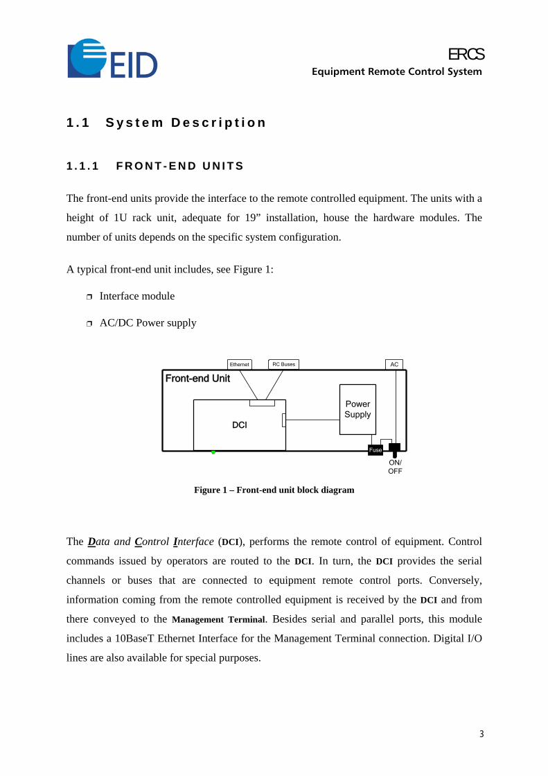
1 . 1 S y s t e m D e s c r i p t i o n
1 . 1 . 1 F R O N T - E N D U N I T S
The front-end units provide the interface to the remote controlled equipment. The units with a
height of 1U rack unit, adequate for 19” installation, house the hardware modules. The
number of units depends on the specific system configuration.
A typical front-end unit includes, see Figure 1:
Interface module
AC/DC Power supply
Front-end Unit
AC
Power Supply
ON/OFF
Fuse
RC BusesEthernet
DCI
Figure 1 – Front-end unit block diagram
The Data and Control Interface (DCI), performs the remote control of equipment. Control
commands issued by operators are routed to the DCI. In turn, the DCI provides the serial
channels or buses that are connected to equipment remote control ports. Conversely,
information coming from the remote controlled equipment is received by the DCI and from
there conveyed to the Management Terminal. Besides serial and parallel ports, this module
includes a 10BaseT Ethernet Interface for the Management Terminal connection. Digital I/O
lines are also available for special purposes.
ERCS Equipment Remote Control System
4
It should be noted that the application software, specific to each equipment, runs in the DCI.
This means that all details regarding the particulars of a given equipment, namely the
character string that needs to be sent to it, as well as its response, are hidden from the
Management Terminal software. This solution is aimed at a maximum efficiency, minimising,
at the same time, software configuration and up-grade efforts.
Continuous monitoring of the hardware status is performed within the unit, an alert or
warning being generated whenever a fault is detected. Upon start-up, the various modules run
a self-test program for detection of any malfunction. If any fault is detected, an alert message
will be generated on the Management Terminal.
The ac/dc converter supply power to the unit from the ship’s network (115 Vac). Each DCI
module includes a dc/dc converter that transforms the external dc supply into the voltages
required internally.
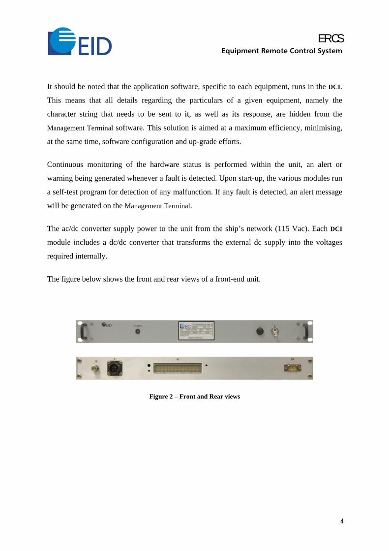
The figure below shows the front and rear views of a front-end unit.
Figure 2 – Front and Rear views
ERCS Equipment Remote Control System
5
The specifications of the front-end unit are as follows:
Remote Control Interfaces ........................ RS-232/MIL-STD-188/RS-422, synchronous or asynchronous
Baud rate: configurable from 75 to 57600
Nº of stop bits: 1, 1.5, 2
Parity: none, odd, even
10 BaseT Ethernet according to IEEE 802.3
Power Supply ............................................... 115/230Vac ± 10%, single phase, 47 to 63Hz
Operating temperature range ........................ 0 to 50º C
Humidity ...................................................... up to 95% non-condensing
1 . 1 . 2 M A N A G E M E N T T E R M I N A L
The Management Terminal, responsible for the overall system control and supervision, consists
of a rugged computer with a 1280x1024 LCD monitor, keyboard and trackball, suitable for
shipboard installation. Alternatively, a PC or Laptop can be used.
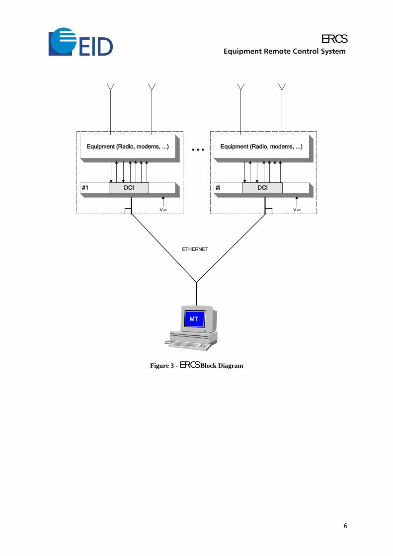
1 . 1 . 3 A R C H I T E C T U R E
The system control structure is shown in Figure 3. The number of front-end units is defined
taking into consideration the quantity and diversity of interfaces required by the system
configuration.
The Management Terminal(s) is connected to the Front-end units through an Ethernet link.
In terms of equipment remote control, the Front-end units include one DCI module that
generate the serial data channels or buses, which in turn are connected to the equipment
control ports.
ERCS Equipment Remote Control System
6
ETHERNET
Equipment (Radio, modems, ...)
#1 DCI
VAC
Equipment (Radio, modems, ...)
#i DCI
VAC
MT
...
Figure 3 - ERCS Block Diagram
ERCS Equipment Remote Control System
7
1 . 2 F u n c t i o n a l A s p e c t s
1 . 2 . 1 R E M O T E C O N T R O L
The system control scope is only limited by the remote control capabilities of each specific
type of equipment. In general, it is possible to remote control quite a diversity of equipment
functions. A continuous, real-time monitoring of the equipment status is also automatically
performed, enabling fault detection of each and every equipment.
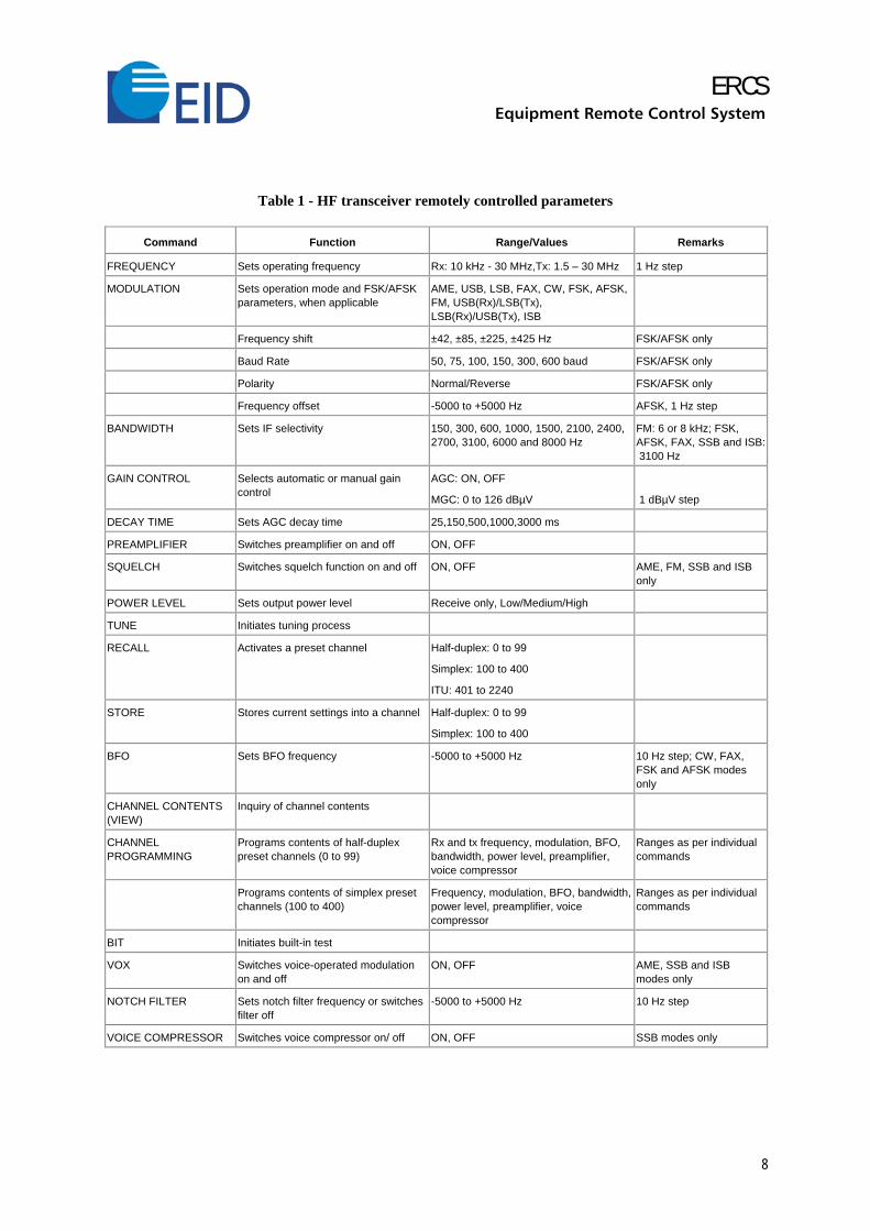
The typical functions under system control for a HF transceiver are listed in Table 1.
As already stressed, the functions associated with remote control are assigned to the
Management Terminal operator. These functions may however be dynamically entrusted to
dedicated remote control units, installed in ship's operational areas such as the operations
room. This is particularly useful when, for operational reasons, users need to have direct
control of the particular radio that they are using.
ERCS Equipment Remote Control System
8
Table 1 - HF transceiver remotely controlled parameters
Command Function Range/Values Remarks
FREQUENCY Sets operating frequency Rx: 10 kHz - 30 MHz,Tx: 1.5 – 30 MHz 1 Hz step
MODULATION Sets operation mode and FSK/AFSK parameters, when applicable
AME, USB, LSB, FAX, CW, FSK, AFSK, FM, USB(Rx)/LSB(Tx), LSB(Rx)/USB(Tx), ISB
Frequency shift ±42, ±85, ±225, ±425 Hz FSK/AFSK only
Baud Rate 50, 75, 100, 150, 300, 600 baud FSK/AFSK only
Polarity Normal/Reverse FSK/AFSK only
Frequency offset -5000 to +5000 Hz AFSK, 1 Hz step
BANDWIDTH Sets IF selectivity 150, 300, 600, 1000, 1500, 2100, 2400, 2700, 3100, 6000 and 8000 Hz
FM: 6 or 8 kHz; FSK, AFSK, FAX, SSB and ISB: 3100 Hz
GAIN CONTROL Selects automatic or manual gain control
AGC: ON, OFF
MGC: 0 to 126 dBµV
1 dBµV step
DECAY TIME Sets AGC decay time 25,150,500,1000,3000 ms
PREAMPLIFIER Switches preamplifier on and off ON, OFF
SQUELCH Switches squelch function on and off ON, OFF AME, FM, SSB and ISB only
POWER LEVEL Sets output power level Receive only, Low/Medium/High
TUNE Initiates tuning process
RECALL Activates a preset channel Half-duplex: 0 to 99
Simplex: 100 to 400
ITU: 401 to 2240
STORE Stores current settings into a channel Half-duplex: 0 to 99
Simplex: 100 to 400
BFO Sets BFO frequency -5000 to +5000 Hz 10 Hz step; CW, FAX, FSK and AFSK modes only
CHANNEL CONTENTS (VIEW)
Inquiry of channel contents
CHANNEL PROGRAMMING
Programs contents of half-duplex preset channels (0 to 99)
Rx and tx frequency, modulation, BFO, bandwidth, power level, preamplifier, voice compressor
Ranges as per individual commands
Programs contents of simplex preset channels (100 to 400)
Frequency, modulation, BFO, bandwidth, power level, preamplifier, voice compressor
Ranges as per individual commands
BIT Initiates built-in test
VOX Switches voice-operated modulation on and off
ON, OFF AME, SSB and ISB modes only
NOTCH FILTER Sets notch filter frequency or switches filter off
-5000 to +5000 Hz 10 Hz step
VOICE COMPRESSOR Switches voice compressor on/ off ON, OFF SSB modes only
ERCS Equipment Remote Control System
9
1 . 2 . 2 C O N T R O L A N D S U P E R V I S I O N
The ERCS control software that runs in the Management Terminal enables the Operator to
perform the following:
Access control and password management
Define users profile
Equipment remote control
Pre-program actions to be executed automatically
Continuous monitor the system status
Inspect logged events
Configuration control (check software and firmware versions)
ERCS Equipment Remote Control System
10
1 . 3 H u m a n - M a c h i n e I n t e r f a c e
In general terms, the Human-machine interface software - supported on a windows-based
graphical user interface - will give the operators access to all ERCS working parameters, so
that appropriate actions can be taken as required. By taking care of all aspects of the system
operation that can be automated, and providing helpful suggestions whenever the opportunity
arises, the operator's job is greatly simplified.
1 . 3 . 1 M A N A G E M E N T T E R M I N A L
1.3 .1 .1 SYSTEM START-UP / ACCESS CONTROL
ERCS is protected against unauthorised use by keeping track of its operators and associated
passwords. If the correct name and password are not given during the LOGIN process, the
system will not accept further commands.
1.3 .1 .2 OPERATORS MANAGEMENT
For the purpose of access control, the system includes facilities to view, add and remove
operator names and associated passwords. The maximum number of operators is a system
configuration.
The system supports several operator access levels. A typical configuration has two access
levels, one for operators and another for supervisors:
Access level 0 - operators have only access to the basic operations.
Access level 1 - supervisors have access to each and every system feature.
The main difference between levels 0 and 1 is the capability to add/remove operators to/from
the system.
Passwords shall be changed periodically. When the password expires, the operator is asked to
change it. If he fails to do so, access is denied.

ERCS Equipment Remote Control System
11
1.3 .1 .3 MAIN WINDOW
After the start-up phase, the system opens the Main window and the respective Login access
control window, providing an overview of the system status. After successful login the user
has access to the complete system functionality.
Figure 4 illustrates a typical HFBB remote control window.
Figure 4 – Main Window
The information elements displayed in the Main window central area are as follows:
Full picture and status of the system
Name of the current operator.
Number of pending alerts.
Date-time group.
ERCS Equipment Remote Control System
12
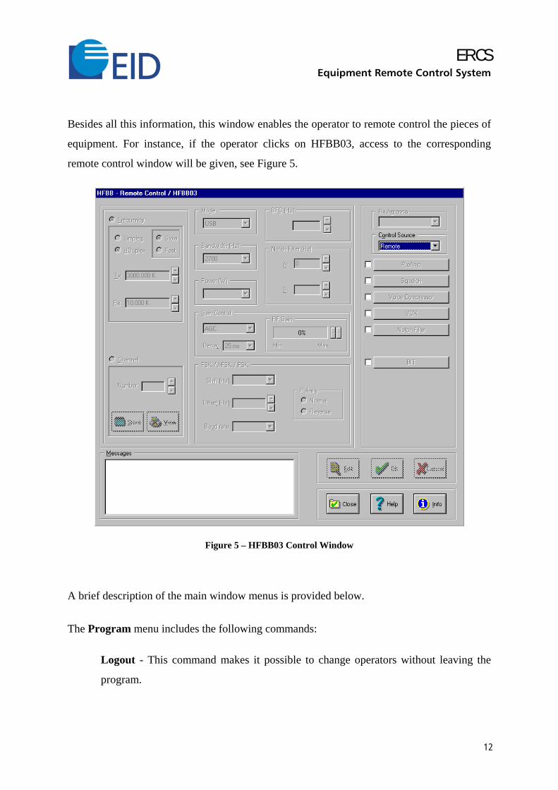
Besides all this information, this window enables the operator to remote control the pieces of
equipment. For instance, if the operator clicks on HFBB03, access to the corresponding
remote control window will be given, see Figure 5.
Figure 5 – HFBB03 Control Window
A brief description of the main window menus is provided below.
The Program menu includes the following commands:
Logout - This command makes it possible to change operators without leaving the
program.

ERCS Equipment Remote Control System
13
Exit - You select this option to terminate program execution. This command opens
the Exit window, which includes only two buttons: OK and CANCEL.
About - This will show you the credits screen: the program name and release,
copyright notice and part number.
The Operators menu includes the Change password and Set-up commands. The former
will let you change your password by opening the Operators/Change Password window.
The latter, only enabled if you have level 1 privilege, opens the Operators/Set-up window,
letting you add and remove operators from the system.
The Equipment menu has the History and Equipment Versions commands. The first lets
you access the equipment management facilities that will show you the changes that occurred
in equipment status. The former gives for all and every remote controlled equipment the
following data:
− remote controlled equipment firmware version.
− equipment firmware version(s) supported by the ERCS remote control software.
The Agenda menu has only the View command. If you select this menu command, the
system will get you into the Agenda window where you have access to the Agenda features.
The Log menu includes the View command, through which you have access to the Log
features, whereby you can view all the recorded events.
The Alerts menu includes the View command, which opens the Alerts window. It will show
you all the pending alerts in the system. If there are no alerts this command is disabled.
Additionally the Notify command enable/disable the automatic view of the alert messages,
whenever an alert occurs.
The Clock menu, through the Set-up command, opens the Clock/Set-up window that will
enable you to change the system time and date.
An on-line help is available at every window of the ERCS, providing a context help.

5090/40070202
This document contains EID, S.A. proprietary information. No part of this document may be used
for other purposes than those for which it has been released, nor reproduced or transmitted to a
third party, in any form or by any means whatsoever, without the prior written permission of EID,
S.A.
EEMMPPRREESSAA DDEE IINNVVEESSTTIIGGAAÇÇÃÃOO EE DDEESSEENNVVOOLLVVIIMMEENNTTOO DDEE EELLEECCTTRRÓÓNNIICCAA,, SS..AA..
RRuuaa QQuuiinnttaa ddooss MMeeddrroonnhheeiirrooss –– LLaazzaarriimm
AAppaarrttaaddoo 553355 –– 22882211--990011 CChhaarrnneeccaa ddaa CCaappaarriiccaa –– PPOORRTTUUGGAALL
TTeell.. ((++335511)) 221122 994488 669922 ee--mmaaiill uuccnn@@eeiidd..pptt
FFaaxx ((++335511)) 221122 994488 669955 hhttttpp::////wwwwww..eeiidd..pptt