Standard Product Reference Sheet GSPW1651NSE 30Z TR Features

Operation Manual Second Edition
ERC Actuator with Integrated Controller

CAUTION 1. Enabling/Disabling the Pause Signal (*STP)
The pause signal uses the contact B logic to provide a failsafe function. Therefore, this signal must remain ON in normal conditions of use. Since there are applications where this signal is not used, a parameter is provided to disable the pause signal so it doesn’t have to be turned ON. To select a desired setting, set “0” or “1” in user parameter No. 15 (Pause input disable selection).
Setting Enable (use) the signal 0 Disable (do not use) the signal 1
The factory setting for this parameter is “0: [Enable].”
2. Recommendation for Backing up Latest Data
The controller part of this actuator uses nonvolatile memory to store the position table and parameters. Normally the memory will retain the stored data even after the power is disconnected. However, the data may be lost if the nonvolatile memory becomes faulty. (We strongly recommend that the latest position table and parameter data be backed up so that the data can be restored quickly in the event of power failure, or when the controller must be replaced for a given reason.) The data can be backed up using the following methods: (1) Save to a CD or FD from the PC software. (2) Hand write the position table and parameter table on paper.
3. Compatibility of Teaching Pendant
The existing teaching pendants of <RCA-T> and <RCA-E> types can be used with the RCP2 controller, but your RCA-T/RCA-E teaching pendant will require some modification. If you are using a teaching pendant of either type, please send it to IAI. We will perform the necessary modification and return it to you as soon as possible. Teaching pendants that have already been modified have a specific code at the end of their serial number. Please check the serial number of your teaching pendant to see if it requires modification.
Teaching pendant model Code at the end of serial number
RCA-T …E3 (or later) RCA-E …G3 (or later) RCA-P …G3 (or later)

Safety Precautions Please read the information in “Safety Precautions” carefully before selecting a model and using the product.
The precautions described below are designed to help you use the product safely and avoid bodily injury and/or property damage.
Directions are classified as “danger,” “warning,” “caution” and “note,” according to the degree of risk.
Danger Failure to observe the instruction will result in an imminent danger leading to death or serious injury.
Warning Failure to observe the instruction may result in death or serious injury.
Caution Failure to observe the instruction may result in injury or property damage.
Note The user should take heed of this information to ensure the proper use of the product, although failure to do so will not result in injury.
This product has been designed and manufactured as a component for use in general industrial machinery.
Devices must be selected and handled by a system designer, personnel in charge of the actual operation using the product or similar individual with sufficient knowledge and experience, who has read both the catalog and operation manual (particularly the “Safety Precautions” section). Mishandling of the product poses a risk.
Please read the operation manuals for all devices, including the main unit and controller.
It is the user’s responsibility to verify and determine the compatibility of this product with the user’s system, and to use them properly.
After reading the catalog, operation manual and other materials, be sure to keep them in a convenient place easily accessible to the personnel using this product.
When transferring or loaning this product to a third party, be sure to attach the catalog, operation manual and other materials in a conspicuous location on the product, so that the new owner or user can understand its safe and proper use.
The danger, warning and caution directions in this “Safety Precautions” do not cover every possible case. Please read the catalog and operation manual for the given device, particularly for descriptions unique to it, to ensure its safe and proper handling.
Danger General
Do not use this product for the following applications: 1. Medical equipment used to maintain, control or otherwise affect human life or physical health 2. Mechanisms and machinery designed for the purpose of moving or transporting people 3. Important safety parts of machinery This product has not been planned or designed for applications requiring high levels of safety. Use of this product in such applications may jeopardize the safety of human life. The warranty covers only the product as it is delivered.

Do not use this product in a place exposed to ignitable, inflammable or explosive substances. The product may ignite, burn or explode.
When installing the product, be sure to provide reliable means for securing/affixing the product (including the load) in place. If the product tips, drops or malfunctions, injury may result.
Avoid using the product in a place where it may come in contact with water or oil droplets. Never cut and/or reconnect the cables supplied with the product for the purpose of extending or shortening the cable length. Doing so may result in fire.
Do not enter the operating range of the machine when the machine is operating or is able to operate. Injury may result due to a sudden movement of the actuator.
Do not pour water onto the product. Spraying water over the product, washing it with water or using it in water may cause the product to malfunction, resulting in injury, electric shock, fire, etc.
Never modify the product. Unauthorized modification may cause the product to malfunction, resulting in injury, electric shock, fire, etc.
Do not disassemble and reassemble the components relating to the basic structure of the product or its performance and function. Doing so may result in injury, electric shock, fire, etc.
Warning
Do not use the product outside the specifications. Using the product outside the specifications may cause it to fail, stop functioning or sustain damage. It may also significantly reduce the service life of the product. In particular, observe the maximum loading capacity and speed.
If the machine will stop in the case of system problem such as emergency stop or power failure, design a safety circuit or other device that will prevent equipment damage or injury.
Be sure to provide Class D grounding for the actuator (formerly Class 3 grounding: Grounding resistance at 100 Ω or less). Leakage current may cause electric shock or malfunction.
Before supplying power to and operating the product, always check the operation area of the equipment to ensure safety. Supplying power to the product carelessly may cause electric shock or injury due to contact with the moving parts.
Wire the product correctly by referring to the operation manual. Securely connect the cables and connectors so that they will not be disconnected or come loose. Failure to do so may cause the product to malfunction or cause fire.
Installation
Operation
Maintenance, Inspection, Repair
General
Installation
Operation
Do not touch the terminal block or various switches while the power is supplied to the product. Failure to observe this instruction may result in electric shock or malfunction.
Before operating the moving parts of the product by hand (for the purpose of manual positioning, etc.), confirm that the servo is turned off (using the teaching pendant). Failure to observe this instruction may result in injury.
The cables supplied with the product are flexible, but they are not robot cables. Do not store the cables in a movable cable duct (cable track, etc.) that bends more than the specified bending radius.
Do not scratch the cables. Scratching, forcibly bending, pulling, winding, crushing with heavy object or pinching a cable may cause it to leak current or lose continuity, resulting in fire, electric shock, malfunction, etc.
Turn off the power to the product in the event of power failure. Failure to do so may cause the product to suddenly start moving when the power is restored, thus resulting in injury or product damage.
If the product is generating heat, smoke or a strange smell, turn off the power immediately. Continuing to use the product may result in product damage or fire.

If the product begins producing noise or vibration has suddenly increased, immediately stop its operation. Continuing to use the product in such condition may cause a product breakdown or damage, resulting in malfunction, runaway, and so on.
If any of the internal protective devices (alarms) of the product have actuated, turn off the power immediately. Continuing to use the product may result in product damage or injury due to malfunction. Once the power supply is cut off, investigate and remove the cause and then turn on the power again.
If the LEDs on the product do not illuminate after turning on the power, turn off the power immediately. Do not climb onto the product or stand or place any object on top. You may slip and injure yourself, and a tipping product or dropping object may also cause injury. Or, a product breakdown or damage may occur, resulting in malfunction, runaway, and so on.
Before conducting maintenance/inspection, parts replacement or other operations on the product, completely shut down the power supply. At this time, take the following measures: 1. Display a sign that reads, “WORK IN PROGRESS. DO NOT TURN ON POWER” in a conspicuous place,
in order to prevent a person other than the operator from accidentally turning on the power. 2. When two or more operators are to perform maintenance/inspection together, always call out every time
the power is turned on/off or an axis is moved in order to ensure safety.
Do not throw the product into fire. The product may burst or generate toxic gases.
Caution
Maintenance, Inspection, Repair
Disposal
Installation
Do not use the product in a place exposed to direct sunlight (UV ray), salt, high humidity or an atmosphere containing organic solvent or phosphate-ester machine oil. The product may lose its function over a short period of time, or exhibit a sudden drop in performance or its service life may be significantly reduced. The product may also malfunction if used in these environments.
Do not use the product in an atmosphere of corrosive gases (sulfuric acid or hydrochloric acid), etc. Rust may form and reduce the structural strength.
When using the product in any of the places specified below, provide a sufficient shield. Failure to do so may result in malfunction: 1. Place where large current or high magnetic field is present 2. Place where welding or other operations are performed that cause arc discharge 3. Place subject to electrostatic noise 4. Place with potential exposure to radiation
Install the product in a place not subject to significant dust and free from iron powder. Installing the product in such a place may cause malfunction.
Do not install the product in a place subject to large vibration or impact (4.9 m/s2 or more). Doing so may result in the malfunction of the product.
Provide an emergency-stop device in a readily accessible position so the device can be actuated immediately upon occurrence of a dangerous situation during operation. Lack of such device in an appropriate position may result in injury.
Provide sufficient maintenance space when installing the product. Routine inspection and maintenance cannot be performed without sufficient space, and an equipment stoppage, product breakdown or injury may result.
When transporting or installing the product, exercise due caution to prevent injury by securely supporting the product using a lift or other supporting equipment, engaging multiple persons to work together, and so on.
Do not hold the moving parts of the product or its cables during installation. It may result in injury. Use IAI’s genuine products for the component units such as the actuator, relay cables and teaching pendant. The brake mechanism of the product is designed to prevent the slider from dropping in a vertical application when the power is turned off. Do not use it as a safety brake (means for reducing the speed) or for any other purpose.
Before installing or adjusting the product or performing other operations on the product, display a sign that reads, “WORK IN PROGRESS. DO NOT TURN ON POWER.” If the power is turned on inadvertently, injury may result due to electric shock or sudden activation of an actuator.

Turn on the power to individual equipment one by one, starting from the equipment at the highest level in the system hierarchy. Failure to do so may cause the product to start suddenly, resulting in injury or product damage.
Do not insert a finger or object in the openings in the product. It may cause fire, electric shock or injury.
Wear protective goggles when applying grease to the actuator. If splashed grease enters the eyes, eye inflammation may result.
When the power is turned off and a cover is opened to replace the battery, etc., do not touch the capacitor connection terminal of the product immediately after the power is turned off (within 30 seconds). Residual voltage may cause electric shock.
Do not touch the terminals when performing an insulation resistance test. Electric shock may result. (Do not perform any withstand voltage test with the product that uses DC voltage.)
Note
If you are planning to use the product under a condition or environment not specified in the catalogs and operation manual, or in an application requiring strict safety such as aircraft facility, combustion system, entertainment machine, clean-room environment, safety device or other equipment having significant impact on human life or property, design operating ranges with sufficient margins from the ratings and design specifications or provide sufficient safety measures such as fail-safes. Whatever you do, always consult IAI’s sales representative.
When the product is to be installed and used in a vertical position, be sure to use the dedicated specification for vertical application (equipped with brake).
Isolate the operating part of the mechanical equipment with a protective cover, etc., to prevent direct contact by the operator or other personnel.
Do not configure a control circuit that will cause the load to drop in case of power failure. Configure a control circuit that will prevent the table or load from dropping when the power to the machine is cut off or an emergency stop is actuated.
Take note of the following items to increase the linearity of table operation and ensure smooth movement of the ball screw and linear guides: 1. The mounting surface of the actuator must have a flatness of 0.05 mm or less. 2. Provide a sufficient installation surface to ensure rigidity of the actuator.
When handling the product, wear protective gloves, protective goggles, safety shoes or other necessary gear to ensure safety.
Use the specified ball screw grease for maintenance. In particular, be careful not to mix fluorine grease with lithium grease, because it may damage the mechanism due to poor lubrication, increased resistance, and so on.
Operation
Maintenance, Inspection, Repair
General
Installation
Maintenance, Inspection, Repair
Installation, Operation, Maintenance
Disposal
When the product becomes no longer usable or necessary, dispose of it properly as an industrial waste.
Others n IAI shall not be liable whatsoever for any loss or damage arising from a failure to observe the items specified
in “Safety Precautions.” n If you have any question regarding the product, please contact your nearest IAI sales office. The addresses
and phone numbers of our sales offices are provided at the end of this operation manual.

Prohibited Handling of Cables When designing an application system using this actuator, incorrect wiring or connection of each cable may cause unexpected problems such as a disconnected cable or poor contact, or even a runaway system. This section explains prohibited handling of cables. Read the information carefully to connect the cables properly.
Ten Rules for Handling Cables (Must be Observed!) 1. Do not let the cable flex at a single point.
2. Do not let the cable bend, kink or twist.
3. Do not pull the cable with a strong force.
4. Do not let the cable receive a turning force at a single point.
6. Do not pinch, drop a heavy object onto or cut
the cable.
5. When fixing the cable, provide a moderate slack and do not tension it too tight.
Steel band (piano wire)
Bundle loosely.
Use a curly cable.
Do not use a spiral tube where the cable flexes frequently.

7. Do not let the cable get tangled or kinked in a cable track or flexible tube. When bundling the cable,
keep a certain degree of flexibility (so that the cable will not become too taut when bent). 8. Do not cause the cables to occupy more than 60% of the space in the cable track. Do not place the connector in the cable track. 9. Always use a robot cable if the cable is likely to flex significantly.
[Standard structure of cable] The standard structure of cable will vary depending on the manufacturer and type of cable.
Cable
Cable track
Absorbing material (When the cable is bent, this material is crushed by the surrounding signal lines to maintain the shape of the signal lines.)
Cover
Shield
Protective layer
Signal line (copper + tin)
H Need for Robot Cables A cable connected to a moving part of an actuator system will inevitably receive repeated bending loads at the base of the cable. As a result, the cores in the cable may break over time. To minimize the risk of cable breakage, we strongly recommend that a robot cable offering significantly higher flexibility be used in this type of application.

Before Use
n Caution
1. Be sure to read this operation manual to ensure the proper use of this product. 2. Unauthorized use or reproduction of a part or all of this operation manual is prohibited. 3. IAI shall not be liable whatsoever for any loss or damage arising from a handling or operation not
specified in this operation manual. 4. The information contained in this operation manual is subject to change without notice.
n Action to Be Taken in Case of Emergency
* If this product is found to be in a dangerous condition, immediately turn off all power switches of the main unit and connected equipment or immediately disconnect all power cables from the outlets. (“Dangerous condition” refers to a situation where the product is generating abnormal heat or smoke or has ignited and a fire or danger to human health is anticipated.)

Table of Contents
1. Note to the User ...................................................................................... 1 1.1 Introduction ...................................................................................................................................... 1 1.2 Safety Precautions........................................................................................................................... 2 1.3 Warranty Period and Scope of Warranty ......................................................................................... 3 1.4 Transportation and Handling............................................................................................................ 4
1.4.1 Handling before Unpacking.................................................................................................... 4 1.4.2 Handling after Unpacking....................................................................................................... 4
1.5 Installation Environment and Noise Elimination............................................................................... 5 1.5.1 Installation Environment......................................................................................................... 5 1.5.2 Storage Environment ............................................................................................................. 5 1.5.3 Power Supply......................................................................................................................... 6 1.5.4 Noise Elimination ................................................................................................................... 6
1.6 Cabling ............................................................................................................................................. 9 1.6.1 Wiring the Optional Cable ...................................................................................................... 9
1.7 Load Applied to the Actuator ............................................................................................................ 9
2. Installation and Wiring........................................................................... 10 2.1 Name of Each Part......................................................................................................................... 10
2.1.1 Slider Type (SA6/SA7) ......................................................................................................... 10 2.1.2 Rod Type (RA54/RA64) ....................................................................................................... 10
2.2 Installation .......................................................................................................................................11 2.2.1 Slider Type ............................................................................................................................11 2.2.2 Rod Type.............................................................................................................................. 12• Affixing with a flange................................................................................................................... 12 • Affixing with foot brackets (optional)........................................................................................... 12 2.2.3 Installing the Load................................................................................................................ 13 • Slider Type.................................................................................................................................. 13 • Rod Type .................................................................................................................................... 14
2.3 Configuration.................................................................................................................................. 16 2.3.1 Basic Structure..................................................................................................................... 16 2.3.2 Using a SIO Converter......................................................................................................... 18 2.3.3 Using an Insulated PIO Terminal Block ............................................................................... 20 2.3.4 Using Both SIO Converter and Insulated PIO Terminal Block............................................. 22
2.4 Controlling Multiple Axes via Serial Communication...................................................................... 24 2.4.1 Basic Specifications ............................................................................................................. 24 2.4.2 Address Assignment ............................................................................................................ 24 2.4.3 Wiring Examples for Linking Multiple Axes .......................................................................... 25
Using only a SIO converter ........................................................................................................ 25 Using both SIO converter and insulated PIO terminal block...................................................... 26
2.5 Emergency-Stop Circuit ................................................................................................................. 27 2.6 Relay Cable.................................................................................................................................... 29

3. Electrical Specifications......................................................................... 31 3.1 Controller........................................................................................................................................ 31 3.2 SIO Converter (Optional: RCB-TU-SIO-A/RCB-TU-SIO-B)........................................................... 32 3.3 Insulated PIO Terminal Block (Optional: RCB-TU-PIO-A/RCB-TU-PIO-B) ................................... 34 3.4 Explanation of I/O Signals.............................................................................................................. 37 3.5 Interface Circuit .............................................................................................................................. 38
3.5.1 External Input Specifications................................................................................................ 38 3.5.2 External Output Specifications............................................................................................. 39
3.6 Details of I/O Signal Functions....................................................................................................... 40 3.6.1 Input Signals ........................................................................................................................ 40
Start (CSTR) ............................................................................................................................... 40 Home return (HOME) ................................................................................................................. 40 Pause (*STP).............................................................................................................................. 40 Command position number (PC1 to PC4).................................................................................. 41
3.6.2 Output Signals ..................................................................................................................... 41 Position complete (PEND).......................................................................................................... 41 Home return completion (HEND) ............................................................................................... 41 Zone (ZONE) .............................................................................................................................. 41 Alarm (*ALM) .............................................................................................................................. 41
4. Data Entry <Basics>.............................................................................. 43 4.1 Description of Position-Data Table................................................................................................. 44
4.1.1 Relationship of Push Force at Standstill and Current-Limiting Value .................................. 46 4.2 Explanation of Modes .................................................................................................................... 48
4.2.1 Positioning Mode Push = 0 .................................................................................................. 48 4.2.2 Push & Hold Mode Push = Other than 0 ............................................................................. 48 4.2.3 Speed Change during Movement ........................................................................................ 50 4.2.4 Operation at Different Acceleration and Deceleration Settings ........................................... 50 4.2.5 Pause................................................................................................................................... 51 4.2.6 Zone Signal Output .............................................................................................................. 51 4.2.7 Home Return........................................................................................................................ 51
5. Operation <Practical Steps>.................................................................. 52 5.1 How to Start.................................................................................................................................... 52 5.2 How to Execute Home Return ....................................................................................................... 53
5.2.1 Home Return Using the Dedicated Input ............................................................................. 53 5.3 Home Return and Movement after Start (Home Return Not Using the Dedicated Input) .............. 54 5.4 Positioning Mode (Back and Forth Movement between Two Points) ............................................ 56 5.5 Push & Hold Mode ......................................................................................................................... 58 5.6 Speed Change during Movement .................................................................................................. 60 5.7 Operation at Different Acceleration and Deceleration Settings...................................................... 62 5.8 Pause ............................................................................................................................................. 64 5.9 Zone Signal Output ........................................................................................................................ 66 5.10 Incremental Moves......................................................................................................................... 68 5.11 Notes on Incremental Mode........................................................................................................... 70
6. Parameters............................................................................................ 72 6.1 Parameter Classification ................................................................................................................ 72 6.2 Parameter Table............................................................................................................................. 72 6.3 Parameter Settings ........................................................................................................................ 73
6.3.1 Parameters Relating to the Actuator Stroke Range............................................................. 73 Soft limit ...................................................................................................................................... 73 Zone boundary ........................................................................................................................... 73 Home return direction................................................................................................................. 74 Home return offset...................................................................................................................... 74
6.3.2 Parameters Relating to the Actuator Operating Characteristics .......................................... 74 Default speed ............................................................................................................................. 74 Default acceleration/deceleration ............................................................................................... 74 Default positioning band (in-position) ......................................................................................... 74 Default acceleration only MAX flag ............................................................................................ 75 Push & hold stop judgment period ............................................................................................. 75 Current-limiting value at standstill during positioning ................................................................. 75 Current-limiting value during home return.................................................................................. 76
6.3.3 Parameters Relating to the External Interface..................................................................... 76 PIO pattern selection .................................................................................................................. 76 Pause input disable selection..................................................................................................... 76 Serial communication speed ...................................................................................................... 76 Minimum delay time for slave transmitter activation .................................................................. 76
6.3.4 Servo Gain Adjustment ........................................................................................................ 76 Servo gain number ..................................................................................................................... 76
7. Troubleshooting..................................................................................... 77 7.1 Action to Be Taken upon Occurrence of Problem.......................................................................... 77 7.2 Alarm Level Classification.............................................................................................................. 77 7.3 Alarm Description and Cause/Action ............................................................................................. 78
(1) Message level alarms .......................................................................................................... 78 (2) Operation-cancellation level alarms..................................................................................... 79 (3) Cold-start level alarms ......................................................................................................... 80
7.4 Messages Displayed during Operation Using the Teaching Pendant or PC Software .................. 81 7.5 Specific Problems........................................................................................................................... 83
I/O signals cannot be exchanged with the PLC. ........................................................................ 83 The LED lamp does not illuminate after the power is input........................................................ 83 The LED illuminates in red when the power is turned on........................................................... 83 Home return ends in the middle in a vertical application............................................................ 83 Noise occurs during downward movements in a vertical application......................................... 83 Vibration occurs when the actuator is stopped. ......................................................................... 84 The actuator overshoots when decelerated to a stop. ............................................................... 84 The home and target positions sometimes shift on the rod-type actuator. ................................ 84 The speed is slow during push & hold operation. ...................................................................... 84
8. Maintenance and Inspection ................................................................. 85 8.1 Inspection Items and Timings ........................................................................................................ 85

8.2 Visual Inspection of Appearance.................................................................................................... 85 8.3 Cleaning ......................................................................................................................................... 85 8.4 Internal Check (Slider Type)........................................................................................................... 86 8.5 Internal Cleaning (Slider Type) ...................................................................................................... 87 8.6 Greasing the Guide (Slider Type) .................................................................................................. 87 8.7 Greasing the Ball Screw (Slider Type) ........................................................................................... 89 8.8 Greasing the Rod Slide Surface .................................................................................................... 90 8.9 Motor Replacement Procedure ...................................................................................................... 91
* Appendix .................................................................................................. 93 Example of Basic ERC Positioning Sequence......................................................................................... 93 Recording of Position-Data Table ............................................................................................................ 96 Recording of User Parameters ................................................................................................................ 97

1. Note to the User 1.1 Introduction Thank you for purchasing the Easy All-in-One Robo Cylinder (hereinafter referred to as “ERC”). This manual explains the features and operating procedures of the product. If not used or handled properly, even a brilliant product cannot fully demonstrate its function or may cause an unexpected breakdown or end its life prematurely. Please read this manual carefully and handle the product with utmost care while ensuring its correct operation. Keep this manual in a convenient place so the relevant sections can be referenced readily when necessary. If you are also using the optional PC software or teaching pendant, also refer to the operation manual for the applicable item. * If you have any question regarding this manual, please contact IAI’s Technical Support. * We have made every effort to ensure accuracy of the information provided in this manual. Should you
find an error, however, or if you have any comment, please contact IAI. Keep this manual in a convenient place so it can be referenced readily when necessary.
1

1.2 Safety Precautions
Read the following information carefully and provide safety measures with due consideration. This product has been developed as a drive component for automated machinery and the like, and is therefore designed not to generate excessive torque or speed beyond the levels needed to drive automated equipment. However, the following instructions must be strictly observed to prevent an unexpected accident. 1. Assume that the product cannot be handled or operated in any manner not specified in this manual,
and do not attempt any such handling or operation. 2. Do not enter the operating range of the machine while the machine is operating or is able to operate
(the controller power is ON). If the machine is used in a place accessible to other people, enclose its operating range using a safety cage, etc.
3. Always turn off the power supply to the controller before assembling/adjusting or
maintaining/inspecting the machine. During assembly/adjustment or maintenance/inspection, put a plate or other visible sign in a conspicuous place indicating that work is in progress. Provide sufficient safety measures to prevent another person from inadvertently plugging in the cable during work.
4. If two or more persons work together, set signaling methods so each person can confirm the safety of
other(s) during work. Especially when the work requires an axis or axes to be moved—with or without the power and by motor drive or manual operation—the person moving each axis should always call out beforehand to ensure safety.
2

1.3 Warranty Period and Scope of Warranty The ERC you have purchased passed IAI’s shipping inspection implemented under the strictest standards. The unit is covered by the following warranty: 1. Warranty Period
The warranty period shall be one of the following periods, whichever ends first: • 18 months after shipment from our factory • 12 months after delivery to a specified location
2. Scope of Warranty
If an obvious manufacturing defect is found during the above period under an appropriate condition of use, IAI will repair the defect free of charge. Note, however, that the following items are excluded from the scope of warranty:
• Aging such as natural discoloration of coating • Wear of a consumable part due to use • Noise or other sensory deviation that doesn’t affect the mechanical function • Defect caused by inappropriate handling or use by the user • Defect caused by inappropriate or erroneous maintenance/inspection • Defect caused by use of a part other than IAI’s genuine part • Defect caused by an alteration or other change not approved by IAI or its agent • Defect caused by an act of God, accident, fire, etc.
The warranty covers only the product as it has been delivered and shall not cover any losses arising in connection with the delivered product. The defective product must be brought to our factory for repair.
Please read carefully the above conditions of warranty.
3

1.4 Transportation and Handling 1.4.1 Handling before Unpacking Exercise due caution when transporting or handling the box containing the actuator, by not applying impact on the box as a result of collision or dropping. • If the box is heavy, one person should not carry it by himself. • Place the box in a level surface. • Do not step on the box. • Do not place on the box any heavy object that may cause the box to deform or other object with a
section where loads will concentrate. 1.4.2 Handling after Unpacking Once removed out of the box, hold the actuator by the frame if it is a rod type, or by the base if it is a slider type. • When carrying the actuator, be careful not to allow it to collide with other objects. In particular, pay
attention to the front bracket, motor bracket and motor cover. • Do not exert excessive force on each part of the actuator. In particular, pay attention to the motor cover
and cables. • When unpacking, exercise due caution not to let the actuator drop and sustain damage to its
mechanism. • If the actuator is damaged during the shipment or any of the items is found missing, please contact IAI’s
Technical Support immediately. Supplement) Refer to 2.1, “Name of Each Part,” for the name of each part of the actuator.
4

1.5 Installation Environment and Noise Elimination
Pay due attention to the installation environment of the controller. 1.5.1 Installation Environment The installation environment must satisfy the following conditions:
No. Use environment/condition
1 Not exposed to direct sunlight.
2 The actuator is not subject to irradiated heat from a large heat source, such as a heat treatment furnace.
3 Ambient temperature of 0 to 40°C.
4 Humidity of 85% or less without condensation.
5 Not exposed to corrosive or flammable gases.
6 Normal environment for assembly and operation not subject to significant dust.
7 Not exposed to oil mist or cutting fluid.
8 Not subject to vibration exceeding 0.3 G.
9 Not exposed to strong electromagnetic waves, ultraviolet light or radiation.
10 Chemical resistance is not considered at all in the design of this product.
11 The actuator and cables are not subject to electrical noise. In general, the installation environment shall be such that the operator can work without wearing any protective gears. 1.5.2 Storage Environment The storage environment shall conform to the installation environment, but special caution is required to prevent condensation if the actuator is to be stored for a long period of time. Unless otherwise specified, the actuator is shipped without any desiccating agent placed in the box. If the actuator is to be stored in an environment subject to condensation, provide a non-condensing measure from outside the box or directly inside the box. The actuator is designed to withstand storage temperatures of up to 60°C for a short period of time. If the storage period will extend beyond one month, however, keep the ambient temperature below 50°C.
5

1.5.3 Power Supply The control/motor-drive power supply specification is 24 VDC ± 10% (2 A max). 1.5.4 Noise Elimination This section explains how to eliminate noise in the use of the controller. (1) Wiring and power supply (a) Provide a dedicated class D grounding using a wire with a size of 0.75 mm2 or larger.
Class D grounding Good Avoid this grounding method.
Actuator with integrated controller
Other equipment
Other equipment
Actuator with integrated controller
(b) Precautions regarding wiring method Separate the controller cables from high-power lines such as a cable connecting to a power circuit. (Do not bundle together the controller cables with high-power lines or place them in the same cable duct.)
6

(2) Noise sources and elimination Among the numerous noise sources, solenoid valves, magnet switches and relays are of particular concern when building a system. Noise from these sources can be eliminated by implementing the measures specified below. (a) AC solenoid valves, magnet switches and relays Measure: Install a surge absorber in parallel with the coil. The most effective method is to connect a surge absorber and a surge killer in parallel.
Point
Install a surge absorber to each coil over a minimum wiring length.Installing a surge absorber to the terminal block or other part will be less effective because of a longer distance from the coil.
Surge absorber Surge killer (CR set)
Surge absorber
This way, noise will be eliminated in the entire range.
7

(b) DC solenoid valves, magnet switches and relays Measure: Install a diode in parallel with the coil. Determine the diode capacity in accordance with the
load capacity. In a DC circuit, connecting a diode in reverse polarity will damage
the diode, internal parts of the controller and/or DC power supply, so exercise due caution.
Diode
8

1.6 Cabling 1.6.1 Wiring the Optional Cable • The optional cable offers excellent resistance against flexure fatigue, but it is not a robot cable.
Therefore, avoid placing the cable in a movable cable duct with a small bending radius. • In an application where the cable cannot be fixed, keep the cable from receiving a deflecting load
exceeding its own weight, use a self-standing cable hose, provide a large bending radius along the wiring path, or provide other measure to minimize the load applied to the cable.
• Do not cut the cable for the purpose of extension, length reduction or reconnection. If you intend to change the cable layout, please consult IAI. 1.7 Load Applied to the Actuator (1) Rod type • Keep the load applied to the rod below the value specified in the catalog. • Make sure the center of the rod axis corresponds to the moving direction of the load.
• Application of lateral load may cause actuator damage or breakdown. • If the rod is subject to lateral load, provide a guide or other support in the
moving direction of the load.
• Do not apply rotating torque to the rod (slide shaft). * It will damage the internal parts.
When tightening the nut at the tip of the rod, do so by holding the rod using a wrench of size 13 (RA54 type) or 17 (RA64 type).
(2) Slider type • Keep the load applied to the slider below the value stated in the applicable specification item. In particular, pay attention to the moment applied to the slider, allowable overhung length and load
capacity. • If the slider is used in an overhung application with the load extending in the Y-axis direction, keep
moments Ma and Mc to one-half the rated moment or less to prevent the base from deforming.
9

2. Installation and Wiring 2.1 Name of Each Part 2.1.1 Slider Type (SA6/SA7) Screw cover Coupling bolt
Connection port for teaching pe
Non-motor end
Right
Left
Top
Bottom
Slider Motor bracket Rea
Base Motor cover Ca
(The arrow on the connector sh
2.1.2 Rod Type (RA54/RA64)
LED
Non-motor end
Right
Left
Front bracket Rear bracket
Motor bracket
Motor cove
Connection port for teac
Rod Frame
Rod end bracket
Top
Bottom
Coupling bolt
(The arrow on the conne
Motor end
Side cover
LEDr cover
Front bracket Rear bracketndant or PC
ble
ould face down.)
Motor end
Rear cover
r Cable
hing pendant or PC ctor should face down.)
10

2.2 Installation 2.2.1 Slider Type • Installing the actuator
The actuator-mounting surface must be a machined surface or have an equivalent flatness. The side and bottom faces of the actuator base are parallel with the guides. If high slide accuracy is required, install the actuator by using these surfaces as references.
Install the actuator in the mounting holes provided in the base. Secure the actuator in place using M4 hex cap bolts.
Slider type • Reduced flatness due to installation of an overhung load will cause the base to deform and inhibit
smooth movement of the slider. If the slider movement becomes heavier on the motor end or the slider begins generating noise, correct the flatness. Otherwise, the slider mechanism may end its life prematurely.
11
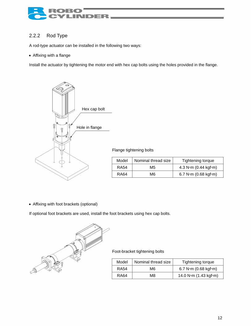
2.2.2 Rod Type A rod-type actuator can be installed in the following two ways: • Affixing with a flange Install the actuator by tightening the motor end with hex cap bolts using the holes provided in the flange.
Flange tightening bolts
Model Nominal thread size Tightening torque RA54 M5 4.3 N m (0.44 kgf m) RA64 M6 6.7 N m (0.68 kgf m)
Hex cap bolt
Hole in flange
• Affixing with foot brackets (optional) If optional foot brackets are used, install the foot brackets using hex cap bolts.
Foot-bracket tightening bolts
Model Nominal thread size Tightening torque RA54 M6 6.7 N m (0.68 kgf m) RA64 M8 14.0 N m (1.43 kgf m)
12

2.2.3 Installing the Load • Slider Type
Four tapped holes are provided in the slider, so affix the load using these holes (indicated by arrows in the figure shown to the left).
Type Slider mounting hole SA6, SA7 M5, depth 9 mm
Nominal thread size Tightening torque Bolt bearing surface: steel Bolt bearing surface: aluminum
M5 7.5 N m (0.77 kgf m) 4.3 N m (0.44 kgf m) The affixing method of the load shall conform to the installation method of the actuator. In an application where the actuator is moved with the slider fixed, install the load using the tapped holes in the slider in the same manner. The slider has two reamed holes. Use these holes when high repeatability is required for load installation/removal. When fine-tuning the squareness of the load, etc., make adjustment by using one of these two reamed holes in the slider.
Type Reamed hole SA6, SA7 φ5, H10, depth 10 mm
13

• Rod Type A bolt is attached on the rod end bracket, so use this bolt to affix the load. (Use the supplied nut, if necessary.)
Rod end bracket
Model Rod end bracket RA54 M8, length 18 mm RA64 M10, length 21 mm
Note) Apply a spanner at the rod end bracket to prevent the rod from receiving any rotating moment when the load is installed.
Applying excessive rotating moment to the rod may damage the rod.
RA54: Width across flats 13 mm RA64: Width across flats 17 mm
14

15

2.3 Configuration 2.3.1 Basic Structure PC software
<RCB-101-MW> Optional
Teaching pendant <RCA-T> Optional
PERSONAL COMPUTER
Cable length: 5 m
Host system <PLC>
Relay cable <CB-ERC-PWBIO * * *> Cable length: 1 m, 3 m, 5 m
← PIO SIO →
ERC actuator
(Not used)
24-VDC control/motor power supply (2 A or more)
Brake release switch Emergency-stop/motor-power cutoff circuit Drain wire
16

Connection diagram
ERC actuator
MC60 mA max
A2 EMS1
B2 EMS2
A4 MPI
B4 GND
A5 MPI
B5 GND
A3 24V
B3 BKR
EMG signal
Input power supply (2 A or more)
Brake release switch
Contact output for EMG switch on teaching pendant Motor drive power supply Control power supply
OFF when the brake is controlled
CN1
Light blue (Red 1)
Light blue (Black 1)
Yellow (Red 1)
Yellow (Black 1)
Pink (Red 1)
Pink (Black 1)
White (Red 1)
White (Black 1)
24V
0V
FG
L
Lig
C
F
by the controller, or ON when the brake is released (Applicable to an actuator with brake)
Host system (PLC)
Out
put
side
In
put
side
(Not used)
Orange (Red 2)
Orange (Black 2)
ight blue (Red 2)
ht blue (Black 2)
White (Red 2)
White (Black 2)
Yellow (Red 2)
Yellow (Black 2)
Pink (Red 2)
Pink (Black 2)
N2
G
A6 PC1 Command position 1
B6 PC2 Command position 2
A7 PC4 Command position 4
B7 HOME Home return
A8 CSTR Start
B8 *STP Pause
A9 PEND Position complete
B9 HEND Home return completion
A10 ZONE Zone output
B10 *ALM Alarm
A1 SGA Serial communication
B1 SGB
Orange (Red 1)
Orange (Black 1)
Drain wire
17

2.3.2 Using a SIO Converter If any of the following conditions applies, use a SIO converter to connect the teaching pendant, PC or PLC’s communication module: • The actuator’s rear cover cannot be reached and therefore the teaching pendant or PC cannot be
connected. • Want to execute movement operation or parameter edit for all axes when multiple axes are connected
to the single equipment. • Want to operate the actuator via serial communication using the PLC’s communication module.
PERSONAL COMPUTER
PC software <RCB-101-MW>
Optional Teaching pendant <RCA-T> Optional
Cable length: 5 m
Host system <PLC>
Relay cable <CB-ERC-PWBIO * * *> Cable length: 1 m, 3 m, 5 m
← PIO
ERC actuator
24-VDC control/motor power supplyBrake release switch Emergency-stop/motor-power cutofDrain wire
TB2 TB1
EM
G2
EM
G1
24V
B A
RS232C cross cable (must be
provided by user)
0V
FG
SIO →
SIO converter <RCB-TU-SIO-A> <RCB-TU-SIO-B>
(2 A or more)
f circuit
18

Connection diagram
MC EMG2
EMG1
TB2
Input power supply
H
EMG signal
Contact output for EMG switch on teaching pendant
SIO converter
60 mAMAX
24VDV
FG
A B
A1 SGA
B1 SGB
L
Li
Lig
Ligh
G
MC
ost system (PLC)
Out
put
side
In
put
side
Brake release switch
ERC actuator
Serial communication
TB1
(Not used)
CN1
Orange (Red 1)
Orange (Black 1)
A4 MPI
B4 GND
A5 MPI
B5 GND
A3 24V
B3 BKR
Motor drive power supply
Control power supply
Yellow (Red 1)
Yellow (Black 1)
Pink (Red 1)
Pink (Black 1)
White (Red 1)
White (Black 1)
24V0V
FG
Orange (Red 2)
Orange (Black 2)
ight blue (Red 2)
ght blue (Black 2)
White (Red 2)
White (Black 2)
Yellow (Red 2)
Yellow (Black 2)
Pink (Red 2)
Pink (Black 2)
ht blue (Red 1)
t blue (Black 1)
A6 PC1 Command position 1
B6 PC2 Command position 2
A7 PC4 Command position 4
B7 HOME Home return
A8 CSTR Start
B8 *STP Pause
A9 PEND Position complete
B9 HEND Home return completion
A10 HEND Zone output
B10 *ALM Alarm
A2 EMS1
B2 EMS2
Drain wire
F19

2.3.3 Using an Insulated PIO Terminal Block If either of the following conditions applies, use an insulated PIO terminal block: • Want to insulate the control power supply from the PIO power supply. • The I/O logic conforms to the PNP specification.
PERSONAL COMPUTER
Optional Cable length: 5 m
Host system <PLC>
Relay cable <CB-ERC-PWBIO- * * * -H6> Cable length: 1 m, 3 m, 5 m
Insulated PIO terminal block <RCB-TU-PIO-A> <RCB-TU-PIO-B>
TB1 TB3
Connector J1
TB4
ERC actuator
24-VDC control/motor powsupply (2 A or more) Brake release switch Emergency-stop/motor-powcutoff circuit
TB2
er
er
PC software <RCB-101-MW>
Optional Teaching pendant <RCA-T>
20

Connection diagram for NPN
Insulated PIO terminal block
MC
TB2
A
B TB1
EMG signal
Connect to FG
Input power supply
Contact output for EMG switch on teaching pendant Motor drive power supply
Control power supply
J1
(Not used)
60 mA Max
Brake release switch
(N
24V
0V
FG
TB4TB3
0V
24V Host system (PLC)
Out
put
side
In
put
side
ote) In the case of a PNP actuator, conne
EMS2
EMS1
BK
MP
24V
0V
FG
Relay cable
1 In-COM
2 PC1 Command position 1
3 PC2 Command position 2
4 PC4 Command position 4
5 HOME Home return
6 CSTR Start
7 *STP Pause
8 PEND Position complete
9 HEND Home return completion
10 ZONE Zone output
11 *ALM Alarm
12 Out-COM
ct 0V to In-COM and 24V to Out-COM.
21

2.3.4 Using Both SIO Converter and Insulated PIO Terminal Block
PERSONAL COMPUTER
Cable length: 5 m
Relay cable <CB-ERC-PWBIO- * * * -H6> Cable length: 1 m, 3 m, 5 m
SIO converter <RCB-T<RCB-T
TB1 TB2
PC software <RCB-101-MW>
Optional Teaching pendant <RCA-T> Optional
U-SIO-A> U-SIO-B>
Connector J1
A B
EMG
EMG
24V
ERC actuator
24-VD(Em
In
TB2
RS232C cross cable (must be
provided by user)
0VFG
TB4
21
C control poergency-sto
24-BraMo
sulated PIO
SIO converter
Host system <PLC>
TB1
TB3
Insulated PIO terminal block <RCB-TU-PIO-A> <RCB-TU-PIO-B>
wer supplyp circuit)
VDC control/motor power supply (2 A or more) ke release switch tor-power cutoff circuit
terminal block
22

Connection diagram for NPN
SIO converter
MC 60 mA Max
TB2
TB1
B
TB1
TB4
TB3
0V
24V
EMG signal
Input power supply
Host system (PLC)
MC Brake release switch
(Not used)
Contact output for EMG switch on teaching pendant
Out
put
side
In
put
side
(Note) In the case of a PNP actuator, conn
EMG2
EMG1
24V
0V
FG
EMS2
EMS1
BK
MP
24V
0V
Insulated PIO terminal block
ect 0V to In-COM and 24V t
A
TB2
Twisted pair
A
B
J1
Connect to FG
FG
24V
0V
FG
Motor drive power supply
Control power supply
Relay cable
1 In-COM
2 PC1 Command position 1
3 PC2 Command position 2
4 PC4 Command position 4
5 HOME Home return
6 CSTR Start
7 *STP Pause
8 PEND Position complete
9 HEND Home return completion
10 ZONE Zone output
11 *ALM Alarm
12 Out-COM
o Out-COM.
23

2.4 Controlling Multiple Axes via Serial Communication The following operations become possible if multiple axes are controlled: (1) Connect the teaching pendant or PC via a SIO converter to execute movement operation or
parameter edit to all axes. (2) Use the PLC’s communication module as a host to perform operation via serial communication by
way of a SIO converter. 2.4.1 Basic Specifications
Specification item Description
Communication format RS485
Transmission speed 115200 bps (9600 bps, 19200 bps or 38400 bps may also be selected)
Maximum number of units that can be connected 16 axes
Maximum cable length 100 m or less
Terminal resistor 120 Ω (built into the SIO converter/insulated PIO terminal block); required if the cable length is 10 m or more.
2.4.2 Address Assignment In a linked configuration where multiple axes are connected via serial communication, the host (teaching pendant, PC or communication module) assigns a slave number to each axis in order to recognize the corresponding actuator. Assign addresses in the setting screen of the teaching pendant or PC. In the actual process of address assignment, the teaching pendant or PC and the target actuator must have a one-on-one link. Therefore, disconnect the communication cables (SGA/SGB) from other axes to tentatively provide a condition where not more than one axis is connected. Refer to the operation manual for the teaching pendant or PC software for the specific operating procedure.
24

2.4.3 Wiring Examples for Linking Multiple Axes
Using only a SIO converter (The same wiring applies to a configuration for automatic operation via serial communication.) Teaching pendant PC PLC’s communication module
TB1
A
B
A
B
A
B
G
Relay terminal block
Actuator 1
Actuator 2
Actuator 3
One-paired shielded cable
SIO converter
(with built-in terminal resistor)
SIO converter
Actuator 16
(Note 1) If a mor
(Note 2) If th(Note 3) Con(Note 4) If th
TB1
communication error occurs whee, connect a SIO converter to the actuators use different power snect the shielded wire of each ae overall length of link cable exc
SG
SG
F
n the overall length of communication cable is 10 m or e last axis. upplies, align 0 [V] on all power supplies.
xis to FG. eeds 30 m, use wire of 22AWG or larger size.
25

Using both SIO converter and insulated PIO terminal block (Communication with the PLC is performed via parallel I/O connection.)
1
SIO converter One-paired
shielded cable
Ins
Teaching pendant PC PLC’s communication module
G
(Note 1) Only on the las(Note 2) If the actuators(Note 3) Connect the sh(Note 4) If the overall le
TB
A
B
TB2
A
B
TB2
A
B
TB2
A
B
2
J1
J1
J1
J1
Actuator 1
Actuator 2
Actuator 3
ulated PIO terminal block
TB
A
B
t axis use dieldedngth o
RTON
FActuator 16
set the terminal-resistor connection switch to the [RTON] side. ifferent power supplies, align 0 [V] on all power supplies. wire of each axis to FG. f link cable exceeds 30 m, use wire of 22AWG or larger size.
26

2.5 Emergency-Stop Circuit Examples of internal circuit and recommended circuit are shown below. ERC Teaching pendant
24V
MC
MC
JP External EMG reset switch
External EMG switch
EMG switch
EMS1
EMS2
24V
MPI
27 Ω
120 Ω
40 mA
Power supply Photorelay
5-V power connection detection
Power supply
Motor drive source
(60 mA MAX)
+
MPI
GND
GND
1
(30 mA)
Motor drive00 µF
0V
27

Example of multi-axes circuit allowing each axis to be connected/disconnected to the teaching pendant
MC M1 M2 M3
D
D
MC
M1
M2
M3
2
2
2
External EMG reset switch
External EMG switch
Actuator 1
Actuator 2
Actuator 3
Teaching pendant EMG switch
Teaching pendant EMG switch
Actuator 1
Actuator 2
Actuator 3
24V 0V
M1
M2
M3
MP1 GND
MP1 GND
MP1 GN
MP1 GN
MP1 GND
MP1 GND
EMS1 EMS
EMS1 EMS
EMS1 EMS
Teaching pendantEMG switch
28

2.6 Relay Cable
Standard specification CN2
(J.S.T. Mfg.) V0.5 - 3
1
OraOra
Socket contact
CB-ERC-PWBIO * * *
. Mfg.
(Supplied cab
Housing:
B A
J.S.TV 0.5 - 3
AMP
D-2100
(Note) Conne
To preIf multrequire
100
1A1B2A2B3A3B4A4B5A5B6A6B7A7B8A8B9A9B10A10B
SGA SGB
EMS1 EMS2 24V BKR MPI GND MPI GND PC1 PC2 PC4
HOME CSTR *STP PEND HEND ZONE *ALM
Orange (R
Orange (B
Light blue (R
Light blue (B
White (R
White (B
Yellow (R
Yellow (B
Pink (R
Pink (B
Orange (R
Orange (B
Light blue (R
Light blue (B
White (R
White (B
Yellow (R
Yellow (B
Pink (R
Pink (B
Housing: 1-1318115-9 (AMTab contact: 1318112-1
)
SGA SGB
1 2
XMP-02V (J.S.T. Mfg.) : SXA-001T-P0.6
1
Drain wire Shielded wire
les to be connected to CN2)
Connector on CN2 end
Housing: XMR-02V (J.S.T. Mfg.) Pin contact: SXM-001T-P0.6
Signal name Pin name Signal name
CN2
Wire color Signal name Pin name Red SGA 1
Black SGB 2
cting 24V to the SGA/SGB serial-communication lines will cause a breakdown. vent miswiring, a two-pin connector is installed at the ends of the applicable lines.iple axes are linked, connect these supplied cables to the CN2 connector and exted, or cut them off at the base of the CN2 connector and install crimp terminals dire
109 8 7 6 5
4
3
2
ed 1)
lack 1)
r
Wire color nge (Red 1) nge (Black 1ed 1)
lack 1)
ed 1)
lack 1)
ed 1)
lack 1)
ed 1)
lack 1)
ed 2)
lack 2)
ed 2)
lack 2)
ed 2)
lack 2)
ed 2)
lack 2)
ed 2)
lack 2)
P)
100
Actuator end CN1
CN
Pinname
Wire colond as ctly.
29

Using an insulated PIO terminal block
HR
A B
1098
10
9
8
7
6
5
4
3
2
1
Terminal-block end CN2
(J.S.T. Mfg.) V0.5 - 3
Wire color Signal name Pin name
Drain w
ousing: 1-1318118-9 (AMP) eceptacle contact: 1318108-1
6
50
1A 1B 2A 2B 3A 3B 4A 4B 5A 5B 6A 6B 7A 7B 8A 8B 9A 9B 10A 10B
SGA SGB
EMS1 EMS2 24V BKR MPI GND MPI GND PC1 PC2 PC4
HOME CSTR *STP PEND HEND ZONE *ALM
Orange (Red 1) Orange (Black 1)
Light blue (Red 1)
Light blue (Black 1)
White (Red 1)
White (Black 1)
Yellow (Red 1)
Yellow (Black 1)
Pink (Red 1)
Pink (Black 1)
Orange (Red 2)
Orange (Black 2)
Light blue (Red 2)
Light blue (Black 2)
White (Red 2)
White (Black 2)
Yellow (Red 2)
Yellow (Black 2)
Pink (Red 2)
Pink (Black 2)
CN2
CB-ERC-PWBIO * * * -H
PC4 HOME CSTR *STP PEND HEND ZONE *ALM
Orange
Orange
Light blue
Light blue
White
White
Yellow
Yellow
Pink
Pink
Orange
Orange
Light blue
Light blue
White
White
Yellow
Yellow
Pink
Pink
Signal name Wire c
CN1
ire Shielded wire
Housing: 1-1318115-9 (Tab contact: 1318112-1
AM
P
0-2100 1 9 8 7 6 5 4 3 2 1
1A1B2A2B3A3B4A4B5A5B6A6B7A7B8A8B9A9B10A10B
SGA SGB
EMS1 EMS2 24V BKR MPI GND MPI GND
PC2 PC1
B A
7
6 5 4Actuator end CN1
3
2 1
olor
Pin name (Red 1)(Black 1)
(Red 1)
(Black 1)
(Red 1)
(Black 1)
(Red 1)
(Black 1)
(Red 1)
(Black 1)
(Red 2)
(Black 2)
(Red 2)
(Black 2)
(Red 2)
(Black 2)
(Red 2)
(Black 2)
(Red 2)
(Black 2)
AMP)
30

3. Electrical Specifications 3.1 Controller
Specification item Description
Number of controlled axes 1 axis/unit
Supply voltage 24 VDC ±10%
Supply current 2 A max.
Control method Weak field-magnet vector control (patent pending)
Positioning command Position number specification
Position number Maximum 8 points
Backup memory Position number data and parameters are saved in nonvolatile memory. Serial EEPROM can be rewritten 100,000 times.
PIO 6 dedicated inputs/4 dedicated outputs
LED indicator Servo ON (green)/Alarm (red)
Communication RS485 1 channel (terminated externally)
Forced release of electromagnetic brake The user must provide a selector switch. (Forced release is actuated by connection to 0V.)
Relay cable length 10 m or less
Insulation strength 500 VDC, 10 MΩ
Environment Operating temperature 0 to 40°C
Operating humidity 85%RH or less (non-condensing)
Operating environment Not subject to corrosive gases.
Storage temperature -10 to 65°C
Storage humidity 90%RH or less (non-condensing)
Vibration resistance 10 to 57 Hz in XYZ directions / Pulsating amplitude: 0.035 mm (continuous), 0.075 mm (intermittent)
Protection class IP20
Weight Approx. 32 g
External dimensions 109 W x 40 D (mm), printed circuit board
31

3.2 SIO Converter (Optional: RCB-TU-SIO-A/RCB-TU-SIO-B) This unit is required if any of the following conditions applies: (1) The actuator’s rear cover cannot be reached and therefore the teaching pendant or PC cannot be
connected. (2) Want to execute movement operation or parameter edit for all axes when multiple axes are
connected to the single equipment. (3) Want to operate the actuator via serial communication using the PLC’s communication module.
Explanation of functions
TB1
A B
TB2
EM
G2 1 V V G
LED1 LED2
RS232
(2) (1) Power/emergency-stop terminal block (TB2)
(6) Monitor LEDs
(4) M
(3) D-sub, 9-pin connector
(1) Power/emergency-stop terminal block (TB2)
Provide a contact output for the emergency-stop switcEMG1 and EMG2 connect to the emergency-stop switPORT switch is ON, or are shorted when the PORT swThese terminals comprise an interlock with a safety cirPositive side of the 24-V power supply (power supply conversion circuit) Negative side of the 24-V power supply
EMG1, EMG2
24V 0V FG FG of the 24-V power supply
(2) Link-connection terminal block (TB1) A connection port for linking the controller. “A” on the left side connects to SGA (wire color: orange/red 1) in
insulated PIO terminal block TB2. “B” on the right side connects to SGB (wire color: orange/black 1
insulated PIO terminal block TB2. (Note) Be sure to use twisted pair wires for the above two line (3) D-sub, 9-pin connector A connection port with the host PC or PLC’s communication mo (4) Mini DIN, 8-pin connector A connection port with the teaching pendant.
Link-connection terminal block (TB1)
EM
G 24 0 F
PORT
ON
SW1
h
ini DIN, 8-pin connector
(5) PORT switc
h on the teaching pendant (RCA-T/E).ch on the teaching pendant when the itch is OFF. cuit provided by the user.
for the teaching pendant and
the relay cable or “A” on the
) in the relay cable or “B” on the
s (SGA/SGB).
dule.
32

(5) PORT switch A switch for enabling/disabling the teaching pendant. Set the switch to ON when a teaching pendant is used, or OFF when teaching pendant is not used. (6) Monitor LEDs LED1 --- Lit when the controller is transmitting LED2 --- Lit when the RS232 is transmitting
33

3.3 Insulated PIO Terminal Block (Optional: RCB-TU-PIO-A/RCB-TU-PIO-B) This unit is required if either of the following conditions applies: (1) Want to insulate the control power supply from the PIO power supply. (2) The I/O logic conforms to the PNP specification. [Internal connection diagram]
er sControl pow
H
Shielded
Connector J1
For direct connectionwith ERC (20-pin connector)
TB2
SGASGB
EMS1EMS2upplyBKRMPI
0VMPI
0V
C
GND
LED1 GND
RTON
LED11
Ω GND
TB1
TB3
560 Ω 3.3 KΩ
Nonpolar input photocoupler COMMON
6 circuits 6 circuits
0V (N)
24V
MP
BK
EMS1 EMS2
In-COM
PC1
PC2
PC4
HOME
CSTR
PC1
PC2
PC4
OME
STR
*STP
LED7Ω
24V
COMMON
Fusing chip resistor (1/10 W 27 Ω)
4 circuits
LED6
4 circuits
*STP
PEND
HEND
ZONE
*ALM
TB41
wire
GND
2.4 K
000PF 630V
1000PF 630 V
24 V LED10
GND RT = 120
SGA SGB
PEND
HEND
ZONE
*ALM
Out-COM
R21
R22
R23
R24
34

Explanation of functions
FG
0V
24V
1 2
A B R
1 2 3 4 5 6 7 8 9
connector (J1) block (TB4)
(5) Terminal-resistor connection swit
(4) Relay (3) Ground terminal
(2) )
(1) Power/emergency-stop terminal block (TB1)
Provide a contact output for the emergency-stop switEMS1 and EMS2 are provided to comprise an interlouser when a teaching pendant with emergency-stop the rear cover. Connection port for the brake release switch Motor power supply port Positive side of the 24-V control power supply
EMS1, EMS2
BK
MP
24V
0V Negative side of the 24-V control power supply (2) Link-connection terminal block (TB2)
A connection port for linking a SIO converter, if used. “A” on the left side connects to link-connection terminal block (“B” on the right side connects to link-connection terminal block(Note) Be sure to use twisted pair wires for the above two lin
(3) Ground (FG) terminal block (TB4)
• A connection port for the relay cable’s shielded wire (drain w• Connection port for the ground wire leading to the enclosure
(4) Relay connector (J1)
A connector port for the relay cable (CB-ERC-PWBIO-***-H6). (5) Terminal-resistor connection switch
If a SIO converter is used and the link cable is long (10 m or mwill be required to prevent signal reflection. This unit can be used in the above application, because the TBresistor. Setting this switch to the [RTON] side will connect the terminal
MP
B
K
EM
SE
MS
10 11 12
(1) Power/emergency-stop terminal block (TB1)
TON
ch
(6) PIO-connection terminal block (TB3)
Link-connection terminal block (TB2
ch on the teaching pendant (RCA-T/E).ck with a safety circuit provided by the switch is connected to the connector on
A) on the SIO converter. (B) on the SIO converter. es (SGA/SGB).
ire). .
ore, as a guideline), a terminal resistor
2 terminal block has a built-in terminal
resistor of approx. 120 Ω.
35

(6) PIO-connection terminal block (TB3) A connection port with the PLC.
No. Signal abbreviation Signal name Remarks
1 In-COM Input common, 24V (NPN) / 0V (PNP) LED11 is lit while 24 V is supplied. 2 PC1 Command position 1 input LED1 is lit while this signal is ON. 3 PC2 Command position 2 input LED2 is lit while this signal is ON. 4 PC4 Command position 4 input LED3 is lit while this signal is ON. 5 HOME Home return input LED4 is lit while this signal is ON. 6 CSTR Start input LED5 is lit while this signal is ON. 7 *STP Pause input LED6 is lit while this signal is ON. 8 PEND Position complete output LED7 is lit while this signal is ON. 9 HEND Home return completion output LED8 is lit while this signal is ON.
10 ZONE Zone output LED9 is lit while this signal is ON. 11 *ALM Alarm output LED10 is lit while this signal is ON. 12 Out-COM Output common, 0V (NPN) / 24V (PNP)
Input Specifications
Specification item Description Number of input points 6 points
Input voltage ± 24V ± 10% Input current 7 mA/point (bipolar)
Allowable leak current 1 mA/point (approx. 2 mA in normal temperature) Operating voltage (with respect
to GND) Input ON: ± 16 V or more (4.5 mA) / OFF: ± 5 V or less (1.3 mA)
Output Specifications
Specification item Description Number of input points 4 points
Rated load voltage ± 24V Maximum current ± 60 mA/point Residual voltage 2 V or less/60 mA
Shorting/overcurrent protection Fusing resistor (27 Ω, 0.1 W)
36

3.4 Explanation of I/O Signals
Category Signal name Signal abbreviation Function overview
Input Start CSTR Movement is started at a rise edge of this signal.
Home return HOME Home return is started at a rise edge of this signal.
*Pause *STP ON: Actuator can be moved, OFF: Actuator decelerates to a stop
Command position number
PC1 PC2 PC4
The target position number is input. A command position number must be specified by 6 ms before the start signal turns ON.
Output Position complete PEND
This signal turns ON when the target position was reached and the actuator has entered the specified in-position range. It is used to determine whether positioning has completed.
Home return completion HEND This signal is OFF immediately after the power is input, and
turns ON when home return has completed.
Zone ZONE
This signal is output when home return has completed and the current actuator position is inside the range set by the applicable parameter. It can be used as a limit switch at an intermediate point or as a simple ruler during push & hold operation.
*Alarm *ALM
This signal remains ON in normal conditions of use and turns OFF when an alarm generates or the motor drive power is cut off. It is synchronized with the green/red of the LED.
Note: The signals indicated by * in the table (*STP and *ALM) are based on the negative logic, meaning
that they remain ON in normal conditions of use.
37

3.5 Interface Circuit The ERC’s standard interface specification is NPN. If you want to use the actuator based on the PNP interface specification, an insulated PIO terminal block (optional) will be required. 3.5.1 External Input Specifications
Item Specification Number of input points 6 points
Input voltage 24 VDC ± 10% Input current 4 mA/point Leak current 1 mA/point or less
Operating voltage (with respect to GND) Input ON: 6 V or more (3.5 mA) / OFF: 18 V or less (1 mA)
Internal circuit configuration
ERC
FUSE
GND 5.6 KΩ
GND
GND
18 V > = “0” 6 V < = “1”
Vin
External power supply24 VDC
Each input
Each input
Power supply (VP24)
Internalcircuit
38

3.5.2 External Output Specifications
Item Specification
Number of input points 4 points
Rated load voltage 24 VDC
Maximum current 60 mA/point
Residual voltage 2 V or less
Shorting/reverse-voltage protection Fusing resistor (27 Ω, 0.1 W) Internal circuit configuration
ERC
Power supply (VP24) FUSE
GND
27 Ω 0.1 W
GND
4 output points
Internal circuit
Each output Load
Fusing resistor
Power MOS FET
GND
Each output Load
External power supply 24 VDC
39

3.6 Details of I/O Signal Functions An input time constant is provided for the input signals of this controller part, in order to prevent malfunction due to chattering, noise, etc. Except for certain signals, switching of each input signal will be effected when the signal has been received continuously for at least 6 msec. For example, when an input is switched from OFF to ON, the controller will only recognize that the input signal is ON after 6 msec. The same applies to switching of input signals from ON to OFF (Fig. 1).
6 [msec] 6 [msec]
Input signal
Recognition by controller
Not recognized
Not recognized
Fig. 1 Recognition of Input Signal 3.6.1 Input Signals
Start (CSTR) Upon detecting a rise (OFF → ON) edge of this signal, the controller will read the target point number as a binary code consisting of three bits from PC1 to PC4, and execute positioning to the target position of the corresponding position data. Before issuing a start command, all operation parameters such as the target position and speed must be set in the nonvolatile memory of the controller. If a start command is issued when home return operation has not been performed yet after the power was input (the HEND output signal is OFF), the controller will automatically perform home return operation before positioning to the target position.
Home return (HOME) The controller will start home return operation upon detection of an OFF → ON edge of this signal. When the home return is complete, the HEND signal will be output. The HOME signal can be input as many times as required. (Note) The HOME signal is not an absolute requirement, because even if home return has not yet been
performed after the power was input, the controller will automatically perform home return operation before positioning to the target position.
Setting “0.00 mm” as the position data will allow for movement to the home. Still, the HOME signal is convenient when there is no space in the position-data table or when the dedicated home switch is available.
Pause (*STP)
When this signal turns OFF while the actuator is moving, the actuator will decelerate to a stop. The remaining movement is retained and will be resumed when the signal is turned ON again. The *STP signal can be used for the following purposes: (1) Provide a low-level safety measure to stop the axis while the servo is ON, such as a sensor that
detects a person approaching the system (2) Prevent contact with other equipment (3) Perform positioning based on sensor or LS detection (Note 1) If the *STP signal is input while the actuator is performing home return, the movement command
will be retained if the actuator is yet to contact a mechanical end. If the signal is input after the actuator has reversed upon contacting a mechanical end, home return will be performed again from the beginning.
(Note 2) This signal can be disabled using user parameter No. 15.
40

Command position number (PC1 to PC4) When a movement command is effected upon OFF → ON of the start signal, the three-bit binary code consisting of signals PC1 to PC4 will be read as the command position number. The weight of each bit is as follows: 20 for PC1, 21 for PC2, and 22 for PC4. A desired position number from 0 to 7 (maximum) can be specified. 3.6.2 Output Signals
Position complete (PEND) This signal indicates that the target position was reached and positioning has completed. When the controller becomes ready after the power was input and the servo has turned ON, this signal will turn ON if the position deviation is within the in-position range. Then, when a movement command is issued by turning ON the start signal, the PEND signal will turn OFF. It will turn ON again when the deviation from the target position falls within the in-position range. Once turned ON, the PEND signal will not turn OFF even when the position deviation subsequently exceeds the in-position range. (Note) If the start signal remains ON, the PEND signal will not turn OFF even when the deviation from
the target position falls within the in-position range: it will turn ON when the start signal turns OFF.
Even when the motor is stopped, the PEND signal will remain OFF if the pause signal is input or the motor drive power is cut off.
Home return completion (HEND)
This signal is OFF immediately after the power is input, and turns ON in either of the following two conditions: (1) Home return operation has completed with respect to the first movement command issued with the
start signal. (2) Home return operation has completed following an input of the home return signal. Once turned ON, this signal will not turn OFF until the input power is cut off or the home return signal is input again. The HEND signal can be used for the following purposes: (1) Check prior to establishing the home if movement toward the home direction is permitted, in cases
where an obstacle is located in the direction of the home (2) Use as a condition for enabling the zone output signal
Zone (ZONE) Use a ZONE signal as a limit switch at an intermediate point or as a simple ruler. This signal will turn ON when the current position is inside the range specified by user parameter Nos. 1 and 2, and turn OFF if the current position is outside this range. (Note) The ZONE signal is enabled after the coordinate system is established following a completion of
home return. It will not be output simply by turning on the power. As long as home return has completed, the ZONE signal remains enabled while the motor drive
power is cut off.
Alarm (*ALM) This signal remains ON while the controller is operating properly, and turns OFF when an alarm has generated. Provide an appropriate safety measure for the entire system by allowing the PLC to monitor the OFF status of this signal. For details of alarms, refer to 7, “Troubleshooting.”
41

(Reference) Output Signal Changes in Each Mode
Mode classification PEND HEND
Actuator is stopped with the servo ON after the power was input ON OFF
Home return is in progress following an input of the home return signal OFF OFF
Home return has completed following an input of the home return signal ON ON
Actuator is moving in the positioning/push & hold mode OFF ON
Actuator is paused in the positioning/push & hold mode OFF ON
Positioning has completed in the positioning mode ON ON
Actuator has stopped after contacting the load in the push & hold mode ON ON
Actuator has stopped after missing the load (no load) in the push & hold mode OFF ON
Motor drive power is cut off after home return OFF ON
(Note) Use PEND to determine whether the actuator has stopped after contacting the load or missing
the load in the push & hold mode.
42

4. Data Entry <Basics> This actuator doesn’t use command words, so there is no need to create a program. All you need is to enter the target position in the position-data table, and the actuator will move to the specified position. Position data consists of number (No.), target position (Position), speed (Speed), acceleration/deceleration (ACC), push (Push), positioning band (Pos. band), and acceleration only MAX (ACC MAX). The description in parentheses is as displayed on the teaching pendant. The target position can be specified in two different modes: by absolute coordinate specification (absolute mode) in which the distance from the home is entered, or by relative coordinate specification (incremental mode) in which the incremental movement from the current position is entered.
Position-data table
No. Position Note Speed Acceleration/ deceleration Push Positioning
band Acceleration
only MAX 0 0 100 0.3 0 0.1 0 1 30 100 0.3 0 0.1 0 2 10 100 0.3 0 0.1 0
~
15
100
100
0.3
0
0.1
0
When data is entered in the position column of the position-data table, the default values will be automatically entered in the remaining columns. Change the default values as necessary. To change a default value, change the corresponding parameters starting with “Default.” The default values vary depending on the actuator type.
This indicates that the incremental mode is active. (This symbol is displayed only on the teaching pendant. Separate columns for incremental specification are provided in the PC software.)
~
Note: Enter position data first. Any attempt to enter other data before position data will be rejected. You can enter position data containing two decimal places. However, the controller only recognizes position data as a multiple of its minimum resolution. The minimum resolution of the controller varies depending on the actuator lead. For the above reason, the second decimal place in the entered position data may be rewritten
in accordance with the actuator lead. Example: Entered value Stored value 50.01 50.03 →
43
~
=~

4.1 Description of Position-Data Table (1) No.
• Indicate the position data number. To enter an incremental movement, press the minus key in this column. On the teaching pendant, a “=” will be displayed between the number and position columns. The minus key need not be pressed in the absolute mode.
(2) Target position (Position)
• Enter the target position to move the actuator to, in [mm]. Absolute mode: Enter the distance to the target actuator position from
the home. Incremental mode: Enter the distance to the target actuator position from
the current position. A negative value can also be entered (for movement in the negative direction along the displayed coordinate axis).
No. Position 0 30 Absolute mode 30 mm from the home 1 10 Incremental mode +10 mm from the current position 2 3
(3) Speed (Speed)
• EnteThe
(4) Acceleration/deceleration
(ACC)
• Entein [GThe
Speed
Start (5) Push (Push)
• SeleThe0: Othe
• To sservto 7
Be suCurrebe aplimitin
=
-10 Incremental mode -10 mm from the current position =
100 Absolute mode 100 mm from the home
r the speed at which the actuator will be moved, in [mm/sec]. default value varies depending on the actuator type.
r the acceleration/deceleration at which the actuator will be moved, ].
default value varies depending on the actuator type.
Acceleration/deceleration (ACC)
Completion Time
Acceleration/deceleration G --- MIN 0.01 G (Slow rise) MAX 1.00 G (Quick rise)
ct the positioning mode or push & hold mode. default value is “0.”
Positioning mode (= Normal operation) r than 0: Push & hold mode [%] elect the push & hold mode, enter the current-limiting value for the o motor during push & hold operation. Enter an appropriate value up 0% in accordance with the actuator type.
re to refer to 4.1.1, “Relationship of Push Force at Standstill and nt-Limiting Value” that specifies the relationship of the push force to plied to the load at standstill [kgf] on one hand, and the current-g value on the other, for each actuator type.
44
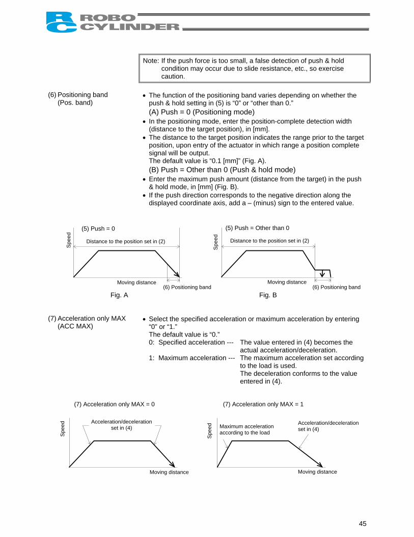
Note: If the push force is too small, a false detection of push & hold
condition may occur due to slide resistance, etc., so exercise caution.
(6) Positioning band (Pos. band)
• The function of the positioning band varies depending on whether the push & hold setting in (5) is “0” or “other than 0.”
(A) Push = 0 (Positioning mode) • In the positioning mode, enter the position-complete detection width
(distance to the target position), in [mm]. • The distance to the target position indicates the range prior to the target
position, upon entry of the actuator in which range a position complete signal will be output.
The default value is “0.1 [mm]” (Fig. A). (B) Push = Other than 0 (Push & hold mode) • Enter the maximum push amount (distance from the target) in the push
& hold mode, in [mm] (Fig. B). • If the push direction corresponds to the negative direction along the
displayed coordinate axis, add a – (minus) sign to the entered value.
Fig. A Fig. B (7) Acceleration only MAX
(ACC MAX) • Select the specified acceleration or maximum acceleration by entering
“0” or “1.” The default value is “0.”
0: Specified acceleration --- The value entered in (4) becomes the actual acceleration/deceleration.
1: Maximum acceleration --- The maximum acceleration set according to the load is used. The deceleration conforms to the value entered in (4).
Spe
ed
Spe
ed (5) Push = 0
Distance to the position set in (2)
(5) Push = Other than 0
Distance to the position set in (2)
Moving distance Moving distance (6) Positioning band (6) Positioning band
(7) Acceleration only MAX = 0 (7) Acceleration only MAX = 1
Acceleration/deceleration
set in (4) Acceleration/deceleration
Spe
ed
Moving distance Moving distance
set in (4) Maximum acceleration according to the load
Spe
ed
45

4.1.1 Relationship of Push Force at Standstill and Current-Limiting Value When performing operation in the push & hold mode, enter the current-limiting value (%) in the push column of the position-data table. Determine the current-limiting value (%) from the push force to be applied to the load at standstill. The graphs below illustrate the relationship of push force at standstill and current-limiting value for each actuator type: (1) RA54 rod type
Low-speed type Medium-speed type
High-speed type
Maximum current-limiting value
Low-speed type 70% Medium-speed type 70%
High-speed type 70%
Note: The accuracy of push force at standstill is not guaranteed. The above graphs are provided for reference purposes only. If the push force is too small, malfunction may occur during push & hold operation due to slide resistance, etc., so exercise caution.
The maximum current-limiting value is shown in the above graphs. The minimum value is 20%.
350
300
250
200
150
100
50
0
160140120100
80604020
020 30 40 50 60 70 20 30 40 50 60 70
Pus
h fo
rce
(N)
Pus
h fo
rce
(N)
Current-limiting value (%) Current-limiting value (%)
Pus
h fo
rce
(N)
Current-limiting value (%)
Rod RA54-3 Rod RA54-6
20 30 40 50 60 70
Rod RA54-12
8070605040302010
0
46

(2) RA64 rod type
Low-speed type Medium-speed type
High-speed type
Maximum current-limiting value
Low-speed type 70% or less Medium-speed type 70% or less
High-speed type 70% or less
Note:
20 30 40 50 60 70
Pus
h fo
rce
(N)
Pus
h fo
rce
(N)
Current-limiting value (%) Current-limiting value (%)
Pus
h fo
rce
(N)
900
800700600500400300200100
0
Rod RA64-4
20 30 40 50 60 70
450
400350300250200150100500
Rod RA64-8
Rod RA64-16
250
200
150
100
50
The accuracy of push force at standstill is not guaranteed. The above graphs are provided for reference purposes only. If the push force is too small, malfunction may occur during push & hold operation due to slide resistance, etc., so exercise caution. The maximum current-limiting value is shown in the above graphs. The minimum value is 20%.
020 30 40 50 60 70
Current-limiting value (%)
47

4.2 Explanation of Modes 4.2.1 Positioning Mode Push = 0 4.2.2 Push & Hold Mode Push = Other than 0 (1) Load was contacted successfully
(1) After reaching the target position, the actuator will move at low speed (75 rpms).
When the Pos. band set in the data table (see Note) is reached after the actuator contacts the load and the stepper motor current has reached the current-limiting value, the position complete output will turn ON.
Note: Set the parameter “Push & hold stop
judgment period.” The default value of “255 [msec]” is already entered.
Position complete signal Output (1) The position complete output will turn
ON at a position preceding the target position by the positioning band.
Spee
d
Moving distance Positioning band
Spee
d
Positioning band Moving distance
Position complete signal Output
The actuator is holding the load in position while pushing it.
Warning The actuator continues to push the load at the push force at standstill determined by the current-limiting value. Since the actuator is not inactive, exercise due caution when handling the machine in this condition.
The push speed is set as follows in accordance with the speed set in the position-data table:
Set speed
20 mm/sec or more Less than 20 mm/sec Push speed 20 mm/sec Set speed
48

(2) Load was not contacted (missed)
(1) After reaching the target position, the actuator will move at low speed (75 rpms).
Even after contacting the load, the actuator will move to the end of the positioning band if the stepper motor current is yet to reach the current-limiting value.
The position complete output will not turn ON even when the end of the positioning band is reached. (Provide a timeout check process after a sufficient period with a PLC.)
(3) Load moves during push & hold operation
(a) Load moves in the pushed direction
If the load moves in the pushed direction after the position complete output has turned ON, the actuator will push the load within the positioning band. The position complete output will remain ON.
(b) Load moves in the opposite direction (Actuator is pushed back by the reactive force of the load)
Spee
d
Moving distance Positioning band
Position complete signal is not output
Spee
d
Moving distance Positioning band
Position complete signal Output
Spee
d
Moving distance
Position complete signal Output
If the actuator is pushed back after the position complete output has turned ON because the actuator thrust is smaller than the reactive force of the load, the actuator will be pushed back all the way until its thrust balances out with the reactive force of the load. The position complete output will remain ON.
49

(4) Positioning band was entered with a wrong sign
If the positioning band is entered with a wrong sign, the position will deviate by twice the positioning band, as shown to the left, so exercise due caution.
4.2.3 Speed Change during Movement Speed control involving multiple speed levels is possible in a single operation. The actuator speed can be decreased or increased at a certain point during movement. However, the position at which to implement each speed change must be set. 4.2.4 Operation at Different Acceleration and Deceleration Settings The actuator will accelerate and decelerate at different speeds if “1” is entered under “Acceleration only MAX” in the position data. The acceleration will conform to the maximum acceleration set according to the load, while the deceleration will conform to the value entered in “Acceleration/deceleration” of the position data.
Spee
d
Moving distance Positioning
band Positioning
band
Maximum acceleration according to the load Deceleration can be set freely
e
Position 1 Position 2 Position 1 Position 2 Position 1 Position 2 Position 3
Spee
d
Tim
50

4.2.5 Pause The actuator can be paused during movement using an external input signal (*pause). The pause signal uses the contact B logic (always ON) to ensure safety. Turning OFF the *pause input will cause the actuator to decelerate to a stop, while turning it ON will allow the actuator to complete the remaining operation.
4.2.6 Zone Signal Output A signal will be output when the actuator enters the specified zone. The zone signal will turn ON when the actuator enters the zone predefined by the applicable parameters. (The zone can be set arbitrarily.)
ON ON OFF *Pause signal
Actuator operation
Zone signal setting range
Actuator operation
Zone signal
4.2.7 Home Return After the power is turned on, home return must be executed to establish the home. Upon occurrence of a cold-start level error, the power must be reconnected to restore the system. In this case, home return is also required after the reconnection of power. There are two ways to execute home return.
Home return using the dedicated input Home return can be executed using the home return (HOME) input. Turning ON this input will execute home return regardless of whether or not it has already been executed once. When the home return is complete, the home return completion (HEND) output will turn ON.
Home return not using the dedicated input
Even if home return has not been executed yet, issuing a start command by specifying a position will cause the actuator to return to the home before moving to the specified position.
H For details, refer to 5.2, “How to Execute Home Return.”
51

5. Operation <Practical Steps> 5.1 How to Start (1) Confirm that the connector end (CN1) of the relay cable is firmly plugged into the connector on the
actuator cable. (2) Connect the PLC and the parallel I/O. (3) If the actuator has brake, set the brake release switch to OFF. (4) Supply 24 VDC to the control/motor-drive power supply. (5) Cancel the emergency stop so that the motor drive power will be supplied. (6) Turn ON the *pause input at the PIO connector. (7) The actuator is working properly if a green LED lamp illuminates at the top of the motor cover. If a red lamp comes on, an alarm is present. Remove the cause of the alarm. For details, refer to Chapter 7, “Troubleshooting.”
Note: Commands from the PLC must be issued after the position complete signal turns ON following the power ON.
The controller is ready once the above operation is completed.
Power ON timing
)
Input of control power
Cancellation of emergency stop (Motor pow
Position
Movement command (hompositioning or push & hold
er supply)
Illumination of green LED
*Alarm output
*Pause input
complete output
If the position complete signal doesn’t turn ON, check if the *pause signal remains remains enabled, or error message is displayed.
(*ALM)
(*STP)
(PEND
e return, ) can be issued.
OFF, any safety circuit
52

5.2 How to Execute Home Return First, force the position complete signal to turn ON by referring to 5.1, “How to Start.” There are two ways to execute home return.
Home return using the dedicated input Home return can be executed regardless of whether or not it has already been executed once.
Home return not using the dedicated input Even if home return has not been executed yet, issuing a start command by specifying a position will
cause the actuator to return to the home before moving to the specified position. Refer to 5.3, “Home Return and Movement after Start.”
5.2.1 Home Return Using the Dedicated Input After turning on the power, execute home return using the home return (HOME) input. When the home return is complete, the home return completion (HEND) output will turn ON.
Home return timing
(HOME)
(PEND)
(HEND)
Home
Home return input Position complete output
Home return completion output
Note: When the home return signal turns ON, the position complete output will turn OFF and the moving output will turn ON. The home return signal must be turned OFF with the confirmation that the home return completion signal has turned ON while the home return signal remains ON.
53
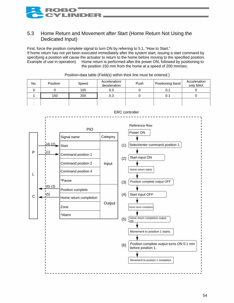
5.3 Home Return and Movement after Start (Home Return Not Using the
Dedicated Input) First, force the position complete signal to turn ON by referring to 5.1, “How to Start.” If home return has not yet been executed immediately after the system start, issuing a start command by specifying a position will cause the actuator to return to the home before moving to the specified position. Example of use in operation) Home return is performed after the power ON, followed by positioning to
the position 150 mm from the home at a speed of 200 mm/sec.
Position-data table (Field(s) within thick line must be entered.)
No. Position Speed Acceleration/ deceleration Push Positioning band Acceleration
only MAX 0 0 100 0.3 0 0.1 0 1 150 200 0.3 0 0.1 0
ERC controller
P L C
(4) (2) (1)
(6) (3) (5)
Signal name Start Command position 1 Command position 2 Command position 4 *Pause Position complete Home return completion Zone *Alarm
Categ
Inpu Outp
Reference flow
PIOory
t
ut
Power ON
Select/enter command position 1.
Start input ON
Home return starts
Position complete output OFF
Start input OFF
Home return completes.
Home return completion output ON
Movement to position 1 starts.
Position complete output turns ON 0.1 mm before position 1.
Movement to position 1 completes.
(1) (2)
(3) (4) (5)
(6)
54

Position 1
Positioning band
Note
T1
Command position
Start
Position complete
Home return completion
SpeedActuator movement Time
Mechanical end Home The position complete output will turn ON when the controller becomes ready following the power ON. To check if the controller is ready, always check if the position complete output is ON. The actuator will not operate unless the pause input is turned ON. T1: 6 msec or more; time after selecting/entering a command position until the start input turns ON (The scan time of the host controller must be considered.)
Note: When the start signal turns ON, the position complete output will turn OFF. The start signal must be turned OFF with the confirmation that the position complete output
has turned OFF while the start signal remains ON. If the start input remains ON as shown below, the position complete output will not turn ON
even when the actuator movement is completed.
Start
Position complete
Actuator
Movement is complete.
55

5.4 Positioning Mode (Back and Forth Movement between Two Points) Example of use in operation) The actuator moves back and forth between two positions. The position 250
mm from the home is set as position 1, and the position 100 mm from the home is set as position 2. The travel speed to position 1 is set as 200 mm/sec, and to position 2 is set as 100 mm/sec.
ERC controller
Signal name Start Command p Command p Command p
*Pause Position com Home return Zone *Alarm
O
(1) (6)
(10) (8) (5) (3)
Reference flow
(9) (7) (4) (2)
P L C
PI
osition 1
osition 2
osition 4
plete
completion
Categ
Inpu Out
ory
t
put
Select/enter command position 1. (1) (2)
(3)
(4)
(5)
(6) (7) (8) (9) (10)
Start input ON
Movement to position 1 starts.
Completed position OFF
Position complete output OFF
Start input OFF
Position complete output ON
Select/enter command position 2.
Movement to position 1 completes.
Start input ON
Movement to position 2 starts.
Position complete output OFF
Start input OFF
Position complete output ON
Movement to position 2 completes.
56

Position-data table (Field(s) within thick line must be entered.)
No. Position Speed Acceleration/ deceleration Push Positioning band Acceleration
only MAX 0 * * * * * * 1 250 200 0.3 0 0.1 0 2 100 100 0.3 0 0.1 0
Position 1 Position 2 Position 1 T1 T1 T1 T1
Command position
Start
Position complete
Speed
Actuator movement
T1: 5 msec or more; time after selecting/entering a command position until the start input turns ON (The scan time of the host controller must be considered.) Each command position must be input after the position complete output has turned ON for the movement to the previous position.
Note: When the start signal turns ON, the position complete output will turn OFF. The start signal must be turned OFF with the confirmation that the position complete output
has turned OFF while the start signal remains ON. If the start input remains ON as shown below, the position complete output will not turn ON
even when the actuator movement is completed.
Start
Position complete
Actuator
Movement is complete.
57

5.5 Push & Hold Mode First, cause the position complete signal to turn ON by referring to 5.1, “How to Start.” Example of use in operation) The actuator is caused to move back and forth in the push & hold
mode and positioning mode. The position 280 mm from the home is set as position 1, and the position 40 mm from the home is set as position 2.
Movement to position 1 is performed in the push & hold mode (the actuator is caused to contact the load and push it in the counter-motor direction). The maximum push amount at position 1 is set as 15 mm, and the current-limiting value during the push & hold operation by the servo motor is set as 50%. Movement to position 2 is performed in the positioning mode. The travel speed to position 1 is set as 200 mm/sec, and that to position 2 is set as 100 mm/sec.
ERC controller
P L C
(9) (7) (4) (2)
(1)
(6) (10) (8) (5) (3)
Signal name Start Command po Command po Command po *Pause Position com Home return Zone *Alarm
O Reference flow
PIsition 1
sition 2
sition 4
plete
completion
Categ
Inpu Out
ory
t
put
Select/enter command position 1.
Start input ON
Movement to position 1 starts.
Position complete output OFF
Start input OFF
Position complete output ON
Select/enter command position 2.
Start input ON
Movement to position 2 starts.
Position complete output OFF
Start input OFF
Movement to position 2 completes.
Move at slow speed after passing position 1.
Load is pushed. Stepper motor current rises to the current-limiting value.
Position complete output turns ON 0.1 mm before position 2.
(1) (2) (3) (4) (5) (6) (7) (8) (9)
(10)
58
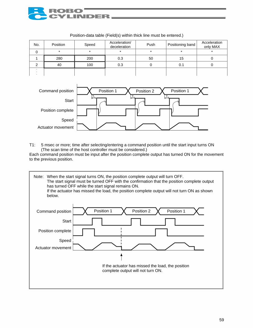
Position-data table (Field(s) within thick line must be entered.)
No. Position Speed Acceleration/ deceleration Push Positioning band Acceleration
only MAX 0 * * * * * *
1 280 200 0.3 50 15 0
2 40 100 0.3 0 0.1 0
Position 1 Position 2 Position 1
Command position
Start
Position complete
Speed
Actuator movement
T1 T1 T1
T1: 5 msec or more; time after selecting/entering a command position until the start input turns ON (The scan time of the host controller must be considered.) Each command position must be input after the position complete output has turned ON for the movement to the previous position.
Note: When the start signal turns ON, the position complete output will turn OFF. The start signal must be turned OFF with the confirmation that the position complete output
has turned OFF while the start signal remains ON. If the actuator has missed the load, the position complete output will not turn ON as shown
below.
If the actuator has missed the load, the position complete output will not turn ON.
Position 1 Position 2 Position 1 Command position
Start
Position complete
Speed
Actuator movement
59

5.6 Speed Change during Movement Example of use in operation) The actuator speed is reduced at a certain point during movement. The position 150 mm from the home is set as position 1, and the position
200 mm from the home is set as position 2. The actuator is initially located between the home and position 1. The actuator is moved to position 2 being the target position, at a travel speed of 200 mm/sec to position 1 and that of 100 mm/sec from position 1 to position 2.
Method) In this example, the actuator is caused to move to position 1 and to position 2 successively. Before the actuator is stopped at position 1, command position 2 must be selected/entered and the start signal must be input. To do this, set a wide positioning band at position 1 and cause the start signal for movement to position 2 to be input immediately after the completion signal for movement to position 1 is output. (Command position 2 should be entered while the actuator is moving to position 1.)
E C controller
P L C
Signal name Start Command position 1
O
Category
Reference flow Select/enter command position 1.
Start input ON
Movement to position 1 starts at 200 mm/sec.
(1) (2)
(9) (7) (4) (2)
(1) (5)
Command pos Command pos *Pause Position comp Home return c Zone *Alarm
(10) (8) (6) (3)
PI
ition 2
ition 4
lete
ompletion
Input Output
R
Position complete output OFF
Start input OFF
Select/enter command position 2.
Start input ON
Position complete output OFF
Start input OFF
Movement to position 2 completes.
Position complete output turns ON 10 mm before position 1.
Movement to position 2 starts at 100 mm/sec.
Position complete output turns ON 0.1 mm before position 2.
(3) (4) (5)
(6) (7) (8) (9)
(10)
60

Position-data table (Field(s) within thick line must be entered.)
No. Position Speed Acceleration/ deceleration Push Positioning band Acceleration
only MAX 0 * * * * * * 1 150 200 0.3 0 10 0 2 200 100 0.3 0 0.1 0
T1 T1
Position 1 Position 2
NoteNote
Command position
Start
Position complete
Speed
Actuator movement
T1: 5 msec or more; time after selecting/entering a command position until the start input turns ON (The scan time of the host controller must be considered.)
Note: When the start signal turns ON, the position complete output will turn OFF. The start signal must be turned OFF with the confirmation that the position complete output
has turned OFF while the start signal remains ON.
61

5.7 Operation at Different Acceleration and Deceleration Settings Example of use in operation) Positioning is performed to the position 150 mm from the home (position 1)
at a speed of 200 mm/sec. The actuator will accelerate at the maximum acceleration set according to the load, and decelerate at 0.1 G.
Method) Entering “1” under “Acceleration only MAX” in the position data will automatically adjust the acceleration to the maximum acceleration set according to the load.
Entering “0.1” under “Acceleration/deceleration” in the position data will set the deceleration to 0.1 G.
P L C
(4) (2) (1) (5) (3)
PIO
Signal name Start Command position 1 Command position 2 Command position 4 *Pause Position complete Home return completion Zone *Alarm
Cate
Inp Ou
ERC controller
gory
ut
tput
Reference flow Select/enter command position 1.
Start input ON
Position complete output OFF
Start input OFF
Movement to position 1 completes.
Position complete output turns ON 0.1 mm before position 1.
Movement to position 1 starts at the maximum acceleration.
Moves at constant speed (200 mm/sec).
Decelerates at 0.1 G.
(1) (2) (3) (4) (5)
62

Position-data table (Field(s) within thick line must be entered.)
No. Position Speed Acceleration/ deceleration Push Positioning band Acceleration
only MAX 0 * * * * * *
1 150 200 0.1 0 0.1 1
Command position
Start
Position complete
Speed
Actuator movement
T1: 5 msec or more; time after sele (The scan time of the host cont
Note: When the start signal turns The start signal must be turn
has turned OFF while the st If the start input remains ON
even when the actuator mov
Start
Position complete
Actuator
Position 1
T1Positioning band
0.1 G Acceleration at maximum motor torque
cting/entering a command position until the start input turns ON roller must be considered.)
ON, the position complete output will turn OFF. ed OFF with the confirmation that the position complete output
art signal remains ON. as shown below, the position complete output will not turn ON ement is completed.
Movement is complete.
63

5.8 Pause Example of use in operation) The actuator is paused during movement.
Method) Use the pause input.
ERC controller
P L C
(4) (2) (1) (6) (5) (7) (3)
PIO
Signal name Start Command position 1 Command position 2 Command position 4 *Pause Position complete Home return completion Zone *Alarm
Ca
I O
(7)
tegory
nput
utput
Reference flow
Select/enter a desired command position.
Start input ON
Position complete output OFF
Start input OFF
Movement to the selected position completes.
Position complete output ON
Movement to the selected position starts.
Pause input OFF (Actuator decelerates to a stop.)
Pause input ON (Movement starts.)
(1)
(2) (3) (4) (5) (6)
64

Deceleration to a stop Start of remaining movement
T1
Note
Command position
Start
Position complete
Pause
Speed
Actuator movement
T1: 5 msec or more; time after selecting/entering a command position until the start input turns ON (The scan time of the host controller must be considered.)
Note: When the start signal turns ON, the position complete output will turn OFF. The start signal must be turned OFF with the confirmation that the position complete output
has turned OFF while the start signal remains ON.
65

5.9 Zone Signal Output Example of use in operation) While the actuator is moving a zone signal is output inside the zone
enclosed by distances of 40 mm and 120 mm from the home. (40 mm ≤ Zone signal output ≤ 120 mm)
Method) Use the parameters “Zone boundary+” and “Zone boundary–” to set the zone in which the zone signal is output, as shown below:
Parameter No. 1 Zone boundary+ 120 Parameter No. 2 Zone boundary– 40
ERC controller
P L C
(4) (2) (1) (7) (3) (6) (5)
PIO
Signal name Start Command position 1 Command position 2 Command position 4 *Pause Position complete Home return completion Zone *Alarm
C
ategory
Input Output
Select/enter a desired command position.
Start input ON
Position complete output OFF
Start input OFF
Movement to the selected position completes.
Position complete output ON
Movement to the selected position starts.
Actuator enters the zone. Zone output ON
Actuator exits the zone. Zone output OFF
Reference flow
(1) (2)
(3) (4) (5) (6) (7)
66

T1
Note
Command position
Start
Position complete
Zone
Speed
Actuator movement
40 mm 120 mm T1: 5 msec or more; time after selecting/entering a command position until the start input turns ON (The scan time of the host controller must be considered.)
Note: When the start signal turns ON, the position complete output will turn OFF. The start signal must be turned OFF with the confirmation that the position complete output
has turned OFF while the start signal remains ON.
Example of other zone output)
Zone output at 120 or more Zone output at 40 or less Zone Zone
120 40
Zone boundary+ Maximum stroke length Zone boundary+ 40
Zone boundary– 120 Zone boundary– 0
67
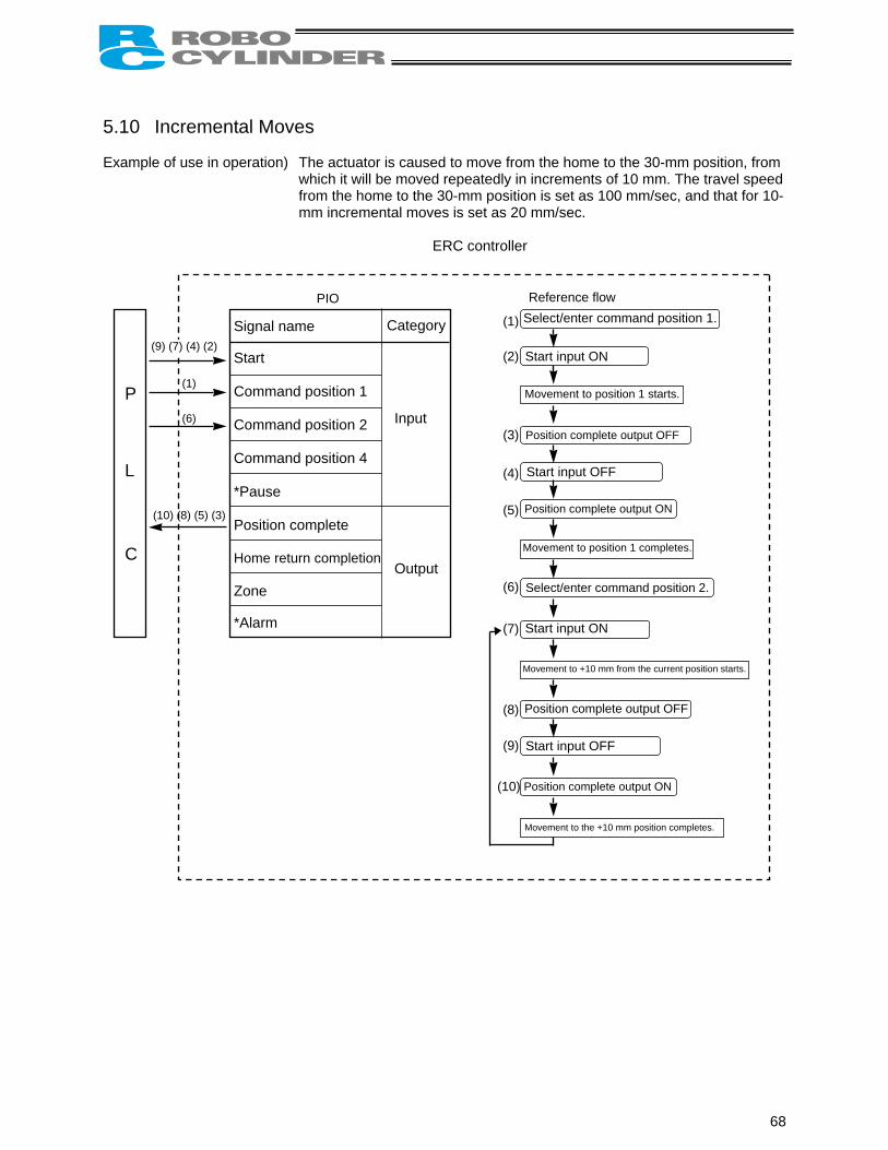
5.10 Incremental Moves Example of use in operation) The actuator is caused to move from the home to the 30-mm position, from
which it will be moved repeatedly in increments of 10 mm. The travel speed from the home to the 30-mm position is set as 100 mm/sec, and that for 10-mm incremental moves is set as 20 mm/sec.
ERC controller
P L C
(1)
(6)
(10) (8) (5) (3)
PIO
Signal name Start Command position 1 Command position 2 Command position 4 *Pause Position complete Home return completion Zone *Alarm
Categ
Inpu Outp
(9) (7) (4) (2)
ory
t
ut
Reference flow Select/enter command position 1.
Start input ON
Movement to position 1 starts.
Position complete output OFF
Start input OFF
Position complete output ON
Select/enter command position 2.
Start input ON
Position complete output OFF
Start input OFF
Movement to position 1 completes.
Movement to +10 mm from the current position starts.
(1
(1) (2) (3) (4)
(5) (6) (7) (8) (9)
Movement to the +10 mm position completes.
Position complete output ON 0)
68

Position-data table (Field(s) within thick line must be entered.)
No. Position Speed Acceleration/ deceleration Push Positioning band Acceleration
only MAX 0 * * * * * * 1 30 100 0.3 0 0.1 0 2 10 20 0.3 0 0.1 0
T1: 5 (T
Note:
Note
=
A
msec or more; time after selecting/entering a command position until the start input turns ON he scan time of the host controller must be considered.)
When the start signal turns ON, the position complete output will turn OFF. The start signal must be turned OFF with the confirmation that the position complete output has turned OFF while the start signal remains ON. If the start input remains ON as shown below, the position complete output will not turn ON even when the actuator movement is completed.
2: When a soft limit is reached as a result of repeated incremental moves, the actuator will stop at that position and the position complete signal will be output.
Start
Position complete
Actuator
Movement is complete.
T1 T1
Command position
Start
Position complete
ctuator movement
Position 1 Position 2
Note 1
Note 2
30 40 50 60 70 Time
Distance from home
Speed
69

5.11 Notes on Incremental Mode (1) Notes on positioning operation
Selecting/entering a position number using relative coordinates during positioning will cause the actuator to move to the position corresponding to the initial position plus the increment. (If the increment is a negative value, the actuator will move to the position corresponding to the initial position minus the increment.) Example) If the start signal for movement to position 2 is input while the actuator is moving to
position 1, the actuator will move to the position 40 mm from the home.
No. Position Speed 0 * * 1 30 100 2 10 100
Command position
Start
Position complete
Speed
Actuator movement
Position from home: 40
Position 1 Position 2
Distance
=
If the start signal for movement to an incremental position number is inpositioning, the actuator will move to the position corresponding to the“increment x number of times the signal was input.” Example) If the start signal for movement to position 2 is input twice w
position 1, the actuator will move to the position 50 mm fro
Position from home: 50
Command position
Start
Position complete
Speed
Actuator movementDistance
Position 1 Position 2 (2) Note on push & hold operation
If the start signal is input with an incremental position number selectedmoving in the push & hold mode, the actuator will move to the positionat the time of start input plus the increment. Therefore, the end position
put multiple times during initial position plus the
hile the actuator is moving to m the home.
/entered while the actuator is corresponding to the position will become indeterminate.
70

Example) If the start signal for movement to position 2 is input while the actuator is moving to position 1 in the push & hold mode, the actuator will move to the position 10 mm from where it was when the input signal was input.
No. Position Speed 0 * * 1 50 100 2 10 100
=
Command position
Start
Position complete
Speed
Actuator movement
Position 1 Position 2
Distance 10 mm
(3) Cumulative errors due to repeated incremental moves
Position data is recognized only as a multiple of the minimum resolutiodetermined by the lead and the number of encoder pulses. Therefore, between the entered position value and the actual movement of the acis repeated, this error will accumulate. The maximum error range for each actuator type is shown below:
ERC model Speed type Lead [mm
Low speed 3 Medium speed 6
ERC -SA6 -RA54
High speed 12 Low speed 4
Medium speed 8
ERC -SA7 -RA64
High speed 16
Example) If an incremental move is repeated 10 times on an ERC-SAa maximum error of 0.02 x 10 = 0.2 [mm] may generate wi
To eliminate these cumulative errors, an absolute command must be etolerance is exceeded.
(4) Ball screw accuracy
The accuracy of the ball screw used in the ERC conforms to C10 unde
n. The minimum resolution is a margin of error may occur tuator. If an incremental move
] Maximum error range [mm]
0.00375 0.0075 0.015 0.005 0.01 0.02
7/RA64 high-speed actuator, th respect to the final position.
xecuted before the error
r the JIS standard.
71

6. Parameters 6.1 Parameter Classification Parameters are classified into four types according to their content. Category:
a: Parameter relating to the actuator stroke range b: Parameter relating to the actuator operating characteristics c: Parameter relating to the external interface d: Servo gain adjustment
6.2 Parameter Table
No. Category Name Unit Default factory setting 1 a Zone boundary 1+ mm Effective actuator length 2 a Zone boundary 1– mm Effective actuator length 3 a Soft limit+ mm Effective actuator length 4 a Soft limit– mm Effective actuator length
5 a Home return direction (0: [Reverse]/1: [Forward]) - (In accordance with the specification at
the time of order) 6 b Push & hold stop judgment period msec 255
7 d Servo gain number - Set individually in accordance with the actuator characteristics.
8 b Default speed mm/sec Set individually in accordance with the actuator characteristics.
9 b Default acceleration/deceleration G Set individually in accordance with the actuator characteristics.
10 b Default positioning band (in-position) mm 0.10 11 b Default acceleration only MAX flag - 0
12 b Current-limiting value at standstill during positioning % Set individually in accordance with the
actuator characteristics.
13 b Current-limiting value during home return % Set individually in accordance with the
actuator characteristics. 14 (Reserved for future extension)
15 c Pause input disable selection (0: [Enable]/1: [Disable]) - 0
16 c Serial communication speed bps 38400
17 c Minimum delay time for slave transmitter activation msec 5
18 (Reserved for future extension) 19 (Reserved for future extension) 20 (Reserved for future extension) 21 (Reserved for future extension) -
22 a Home return offset mm Set individually in accordance with the actuator characteristics.
23 (Reserved for future extension) 24 (Reserved for future extension) 25 c PIO pattern selection - 0
(Note) The numbers are displayed on the PC software screen but not on the teaching pendant. The
category codes are provided only for convenience and not displayed on either the PC software screen or teaching pendant.
72

6.3 Parameter Settings
If a parameter has been changed, always restart the controller using a software reset command or by reconnecting the power.
6.3.1 Parameters Relating to the Actuator Stroke Range
Soft limit Set the soft limit in the positive direction in parameter No. 3, and that in the negative direction in parameter No. 4. The factory setting for the soft limits conforms to the effective actuator length. Change the settings, as necessary, to prevent crash with an obstacle or when the actuator must be stroked slightly beyond its effective length. A wrong soft limit setting will cause the actuator to crash into the mechanical end, so exercise due caution. The minimum setting unit is “0.01 [mm].” (Note) To change a soft limit, set a value corresponding to 0.3 mm outside of the effective range.
Example) Set the effective range to between 0 mm and 80 mm Parameter No. 3 (positive side) 80.3 Parameter No. 4 (negative side) –0.3
Soft limits set in the controller
Approx. 0.3 mm
Effective range
Allowable jogging/inching range after home return
Approx. 0.1 mm
Approx.
8 0 0
0.3 mm
Approx. 0.1 mm
Zone boundary Set the zone in which a zone output signal (ZONE) will turn ON. The zone signal turns ON only when the current coordinate position is inside the negative (-) boundary and positive (+) boundary settings. The positive and negative boundaries for the ZONE signal are set in parameter No. 1 and No. 2, respectively. The minimum setting unit is “0.01 [mm].”
Example) Use the zone output signal as an intermediate limit switch in the range of 100 to 200 mm, with an actuator having a 300-mm stroke Parameter No. 1 (positive side) 200, parameter No. 2 (negative side) 100
0 (Home) 100 200 300 mm
ZONE turns ON
73

Home return direction Unless specified by the user, the home return direction is set to the motor direction at the factory. Should a need arise to change the home direction after the actuator has been assembled into your system, reverse the setting in parameter No. 5 between “0” and “1.” Also change the home return offset, if necessary.
Note: If the home direction is reversed, all position data that have been input will be cleared.
Home return offset The controller is shipped from the factory with an optimal value set in parameter No. 22, so the distance from each mechanical end to the home becomes uniform. The minimum setting unit is “0.01 [mm].” The home return offset can be adjusted in the following conditions: (1) Want to align the actuator home and the system’s mechanical home after the actuator has been
assembled into the system (2) Want to set a new home after reversing the factory-set home direction (3) Want to eliminate a slight deviation generated after replacing the actuator
Note: If the home return offset has been changed, the soft limit parameters must also be adjusted accordingly.
6.3.2 Parameters Relating to the Actuator Operating Characteristics
Default speed The factory setting is the rated speed of the actuator. When a target position is written to an unregistered position table, the setting in this parameter will be used as the speed data for the applicable position number. To reduce the default speed from the rated speed, change the setting in parameter No. 8.
Default acceleration/deceleration The factory setting is the rated acceleration/deceleration of the actuator. When a target position is written to an unregistered position table, the setting in this parameter will be used as the acceleration/deceleration data for the applicable position number. To reduce the default acceleration/deceleration from the rated acceleration/deceleration, change the setting in parameter No. 9.
Default positioning band (in-position) The factory setting is “0.10 [mm].” When a target position is written to an unregistered position table, the setting in this parameter will be used as the positioning band data for the applicable position number. Increasing the default positioning band will allow the position complete signal to be output early. Change the setting in parameter No. 10, as necessary.
74
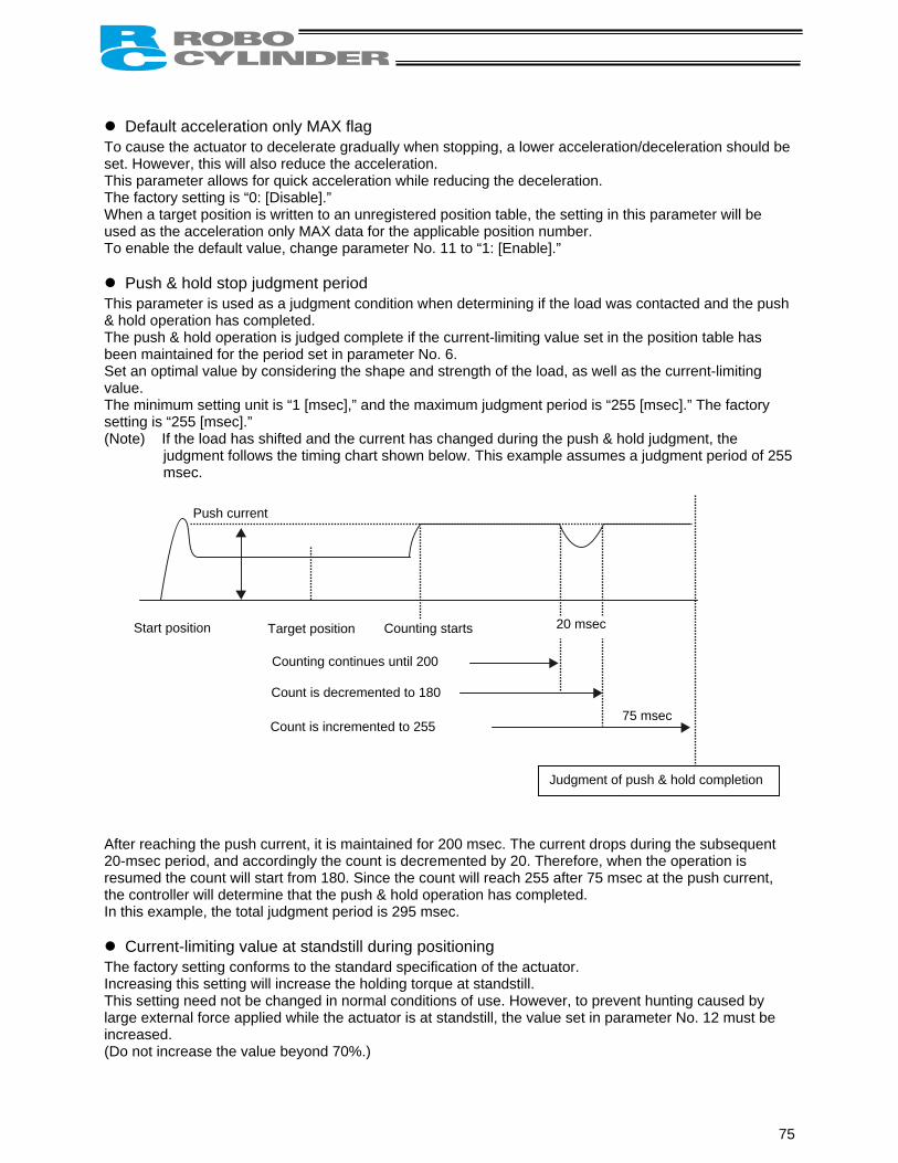
Default acceleration only MAX flag To cause the actuator to decelerate gradually when stopping, a lower acceleration/deceleration should be set. However, this will also reduce the acceleration. This parameter allows for quick acceleration while reducing the deceleration. The factory setting is “0: [Disable].” When a target position is written to an unregistered position table, the setting in this parameter will be used as the acceleration only MAX data for the applicable position number. To enable the default value, change parameter No. 11 to “1: [Enable].”
Push & hold stop judgment period This parameter is used as a judgment condition when determining if the load was contacted and the push & hold operation has completed. The push & hold operation is judged complete if the current-limiting value set in the position table has been maintained for the period set in parameter No. 6. Set an optimal value by considering the shape and strength of the load, as well as the current-limiting value. The minimum setting unit is “1 [msec],” and the maximum judgment period is “255 [msec].” The factory setting is “255 [msec].” (Note) If the load has shifted and the current has changed during the push & hold judgment, the
judgment follows the timing chart shown below. This example assumes a judgment period of 255 msec.
Push current
20 msecStart position Target position Counting starts
Counting continues until 200
Count is decremented to 180
Count is incremented to 255
Judgment of push & hold completion
75 msec
After reaching the push current, it is maintained for 200 msec. The current drops during the subsequent 20-msec period, and accordingly the count is decremented by 20. Therefore, when the operation is resumed the count will start from 180. Since the count will reach 255 after 75 msec at the push current, the controller will determine that the push & hold operation has completed. In this example, the total judgment period is 295 msec.
Current-limiting value at standstill during positioning The factory setting conforms to the standard specification of the actuator. Increasing this setting will increase the holding torque at standstill. This setting need not be changed in normal conditions of use. However, to prevent hunting caused by large external force applied while the actuator is at standstill, the value set in parameter No. 12 must be increased. (Do not increase the value beyond 70%.)
75

Current-limiting value during home return The factory setting conforms to the standard specification of the actuator. Increasing this setting will increase the home return torque. This setting need not be changed in normal conditions of use. However, if an increased slide resistance causes the home return to complete before the correct position depending on the affixing method, load condition or other factor when the actuator is used in a vertical application, the value set in parameter No. 13 must be increased. (Do not increase the value beyond 75%.) 6.3.3 Parameters Relating to the External Interface
PIO pattern selection For future extension, parameter No. 25 is provided to allow for selection of operation pattern. Since only one operation pattern is available at the present, this parameter is set to “0.”
Pause input disable selection Parameter No. 15 defines whether the pause input signal is disabled or enabled.
Setting Enable (use) the signal 0 Disable (do not use) the signal 1
The factory setting is “0: [Enable].”
Serial communication speed Set the communication speed to be used when the control is performed via serial communication using the PLC’s communication module. Set an appropriate value in parameter No. 16 in accordance with the specification of the communication module. One of 9600, 19200, 38400 and 115200 bps can be selected as the communication speed. The factory setting is “38400 [bps].”
Minimum delay time for slave transmitter activation This parameter defines the minimum delay until the controller’s transmitter will be activated after completion of command reception, when serial communication is performed using the PLC’s communication module. The factory setting is “5 [msec],” but other necessary delay time must be set in parameter No. 17 if the specification of the communication module exceeds 5 msec. 6.3.4 Servo Gain Adjustment
Servo gain number The factory setting is optimized in accordance with the standard specification of the actuator. This setting need not be changed in normal conditions of use. However, an increased load may produce noise during downward movements depending on the affixing method, load condition or other factor when the actuator is used in a vertical application. In this case, decreasing the value set in parameter No. 7 will be effective. However, do not decrease the value below “3” to maintain an overall balance with the actuator.
76

7. Troubleshooting 7.1 Action to Be Taken upon Occurrence of Problem Upon occurrence of a problem, take an appropriate action according to the procedure below in order to ensure speedy recovery and prevent recurrence of the problem. a) Check the status indicator lamps.
Illuminating in green --- The servo is ON. Illuminating in red --- An alarm is present or the motor drive power is cut off.
b) Check for error in the host controller. c) Check the voltage of the main 24-VDC power supply. d) Check for alarm. Confirm the details of error on the PC or teaching pendant. e) Check the cables for connection error, disconnection or pinching. Before performing a continuity check, turn off the power (to prevent a runaway actuator) and
disconnect the cables (to prevent accidental power connection due to a bypass current). f) Check the I/O signals. g) Check the noise elimination measures (grounding, installation of surge killer, etc.). h) Review the events leading to the occurrence of problem, as well as the operating condition at the time
of occurrence. i) Match product numbers of actuator to that of controller. Or, record swerial numbers and product
numbers to inform IAI. j) Analyze the cause. k) Take action.
Please check items a) through i) before contacting IAI.
7.2 Alarm Level Classification Alarms are classified into three levels according to the symptoms they represent.
Alarm level LED color *ALM signal What happens when alarm generates How to reset
Message Green Not output An error is displayed on the PC or teaching pendant.
Operation cancellation Red Output
The actuator decelerates to a stop and then the servo turns OFF.
Reset the alarm on the PC/teaching pendant.
Cold start Red Output The actuator decelerates to a stop and then the servo turns OFF.
Reconnect the power.
(Note) Reset each alarm after identifying and removing the cause. If the cause of the alarm cannot be
removed or when the alarm cannot be reset after removing the cause, please contact IAI. If the same error occurs again after resetting the alarm, it means the cause of the alarm has not
been removed.
77

7.3 Alarm Description and Cause/Action (1) Message level alarms Code Error name Cause/Action
41 Motor voltage reduction This alarm indicates that the motor drive power is cut off. (This is not an error.)
5A Receive overrun
5B Receive framing error
5D Header error
5E Delimiter error
7F BCC error
This alarm indicates an error during PC or teaching pendant operation or in the serial communication using the PLC’s communication module. Cause: (1) Garbage data due to the effect of noise (2) Duplicate slave numbers when multiple controllers are controlled by
serial communication Action: (1) Adjust the wiring in a manner eliminating the effect of noise and
review the installation of equipment, etc. (2) Change the slave numbers to avoid duplication.
61 Wrong character string or wrong address error
62 1 Operand error
63 2 Operand error
64 3 Operand error
This alarm indicates an error in the serial communication using the PLC’s communication module. Cause: Undefined command or out-of-range data Action: Review the transmitted data and correct the format.
65 EEPROM WRITEe timeout
Cause: Writing of parameter or position data to the nonvolatile memory area does not complete within 200 ms.
(This alarm will not generate in normal operation.) Action: Do not write data from the PC or teaching pendant simultaneously while a
command is being issued from the PLC. 70 Motion command while
in RUN-OFF condition Cause: A movement command was issued while the motor drive power was cut
off. Action: Issue a movement command after deactivating the safety circuit to supply
the motor drive power. 73 Alarm reset while in
SERVO–ON condition Cause: An alarm reset command was sent while the servo was ON during an
operation by serial communication. (PIO commands are excluded.) Action: Send an alarm reset command after confirming that the servo is OFF.
75 Motion command during Homing
Cause: The next movement command was issued during home return. Action: Issue the next movement command after confirming that the home return
has completed (HEND is ON). 76 Software reset
command while in SERVO-ON condition
Cause: A soft reset command was sent while the servo was ON during an operation by serial communication.
(PIO commands are excluded.) Action: Send a soft reset command after confirming that the servo is OFF.
78

(2) Operation-cancellation level alarms
Code Error name Cause/Action
B0 Data error in memory Bank 30 (Parameter)
Cause: Data in the parameter area is outside the input range or invalid. (This alarm will not generate in normal parameter input operation, but
may occur during serial communication using the PLC’s communication module.)
Action: Transfer data after confirming that the parameter values are valid.
B1 Data error in memory Bank 31 (Point)
Cause: (1) A movement command was issued by selecting a number to which no position data was registered.
(2) Position data value exceeds the soft limit setting. (3) The timing of start signal is varied or too early. Action: (1) Revise the sequence in such a way that unregistered position
numbers will not be selected. (2) Change the position data to a value inside the soft limit settings. (3) The minimum timer setting may not be recognized depending on
the PLC. Pay attention to the timer setting.
B8 Excitation detection error This controller will conduct excitation phase detection when the servo is first turned ON after the power was input. This alarm indicates that the specified encoder signal level cannot be detected after 100 ms of excitation. Cause: (1) Brake cannot be released on a controller equipped with brake. (2) Large motor load due to application of external force (3) Power was input when the actuator was contacting a mechanical
end. (4) Large slide resistance of the actuator itself Action: (1) Turn on/off the brake release switch to see if the brake makes
“click” sounds. (2) Check for abnormality in the assembly condition of mechanical
parts. (3) Move the actuator away from the mechanical end and then
reconnect the power. (4) If the load is normal, cut off the power and move the actuator by
hand to check the slide resistance. This only works if the brake is released. (You cannot release the brake if the power is cut).
If the actuator is suspected to be the cause, please contact IAI. BE Time out error while Homing Cause: Home return does not complete within the period set in the applicable
system parameter after the start of home return operation. Action: This alarm will not generate in normal operation. Should you
encounter the alarm, please contact IAI.
C0 Overspeed error Cause: This alarm indicates that the motor speed exceeded the maximum speed set in the applicable system parameter.
This alarm will not generate in normal operation, but may occur in the following conditions: (1) Large actuator slide resistance in certain area, or (2) Load rises then rapidly releases such that the motor had called for
more power and now has overspeed fault. Action: Check for abnormality in the assembly condition of mechanical parts. If the actuator is suspected to be the cause, please contact IAI.
79

Code Error name Cause/Action
C1 Servo error This alarm indicates that after receiving a movement command the motor is unable to operate for two seconds or more before reaching the target position. Cause: (1) Brake cannot be released on a controller equipped with brake. (2) Large load due to application of external force (3) Large slide resistance of the actuator itself Action: (1) Turn on/off the brake release switch to see if the brake makes
“click” sounds. (2) Check for abnormality in the assembly condition of mechanical
parts. (3) If the load is normal, cut off the power and move the actuator by
hand to check the slide resistance. If the actuator is suspected to be the cause, please contact IAI.
C9 Overvoltage error This alarm indicates that the motor supply voltage is excessive (24V + 20%: 28.8V or more). Cause: (1) High voltage of the 24-V input power supply (2) Faulty controller board component Action: Check the voltage of the input power supply. If the voltage is normal, please contact IAI.
CA Overheat error This alarm indicates that the temperature around the power transistor in the controller board is too high (95°C or higher). Cause: (1) High temperature around the actuator (2) Faulty part inside the controller board Action: Reduce the temperature around the actuator. If the temperature around the actuator is normal, please contact IAI.
CC Abnormal control supply voltage
This alarm indicates that the voltage of the 24-V input power supply is excessive (24 V + 20%: 28.8 V or more). Cause: (1) High voltage of the 24-V input power supply (2) Faulty part inside the controller board Action: Check the voltage of the input power supply. If the voltage is normal, please contact IAI.
CE Control power voltage reduction
This alarm indicates that the voltage of the 24-V input power supply has dropped (24 V – 20%: 19.2 V or less). Cause: (1) Low voltage of the 24-V input power supply (2) Faulty part inside the controller board Action: Check the voltage of the input power supply. If the voltage is normal, please contact IAI.
(3) Cold-start level alarms
Code Error name Cause/Action
F8 EEPROM data corrupt Abnormal data was detected during the nonvolatile memory check after starting.Cause: (1) Faulty nonvolatile memory (2) The memory has been rewritten more than 100,000 times. (The nominal rewrite limit of the nonvolatile memory is around
100,000 times.) Action: If the alarm generates again after reconnecting the power, please
contact IAI. FA CPU error The CPU is not operating properly.
Cause: (1) Faulty CPU (2) Malfunction due to noise Action: If the alarm generates again after reconnecting the power, please
contact IAI.
80

7.4 Messages Displayed during Operation Using the Teaching Pendant or PC
Software This section explains the warning messages that may be displayed during operation using the teaching pendant or PC software.
Code Error name Cause/Action
112 Invalid data An inappropriate value was entered in a user parameter. (Example) 9601 was entered as the serial communication speed by mistake. Enter an appropriate value again.
113 114
Value too small Value too large
The entered value is smaller than the setting range. The entered value is larger than the setting range. Refer to the actuator specifications or parameter table and enter an appropriate value again.
115 Home return non-completion The current position was written when home return was not yet completed. Execute home return again.
116 Last position data Data already exists in the last position area of the position table when new data is added. Clear or delete the current last position data first.
117 No movement data Target position is not set under the selected position number. Enter the target position first.
11E Paired data mismatch The values indicating the magnitude relationship of a pair of data are inappropriate. (Example) The same value was entered in both the parameters for + and – soft
limits. Enter appropriate values again.
11F Absolute position too small The minimum movement toward the target position is determined by the lead length of the drive system and resolution of the encoder. This message indicates that the entered target value is smaller than the minimum movement. (Example) If the lead length is 16 mm, the encoder’s resolution is 800 pulses
and accordingly the minimum movement becomes 16 ÷ 800 = 0.02 mm/pulse.
In this case, this message will be displayed if 0.01 mm is entered as the target position.
121 Push & hold search end over
The final position in push & hold operation exceeds the soft limit. This has no negative effect if the actuator contacts the load. If the actuator misses the load, however, the soft limit will be reached and thus this message is displayed as a warning. Change either the target position or positioning band.
122 Multiple axes connected at assignment
Address was assigned when multiple axes were connected. Assign each address only when one axis is connected.
180 181 182
Address change OK Controller initialization OK Home change all clear
These messages are displayed to confirm operation. (They don’t indicate an operation error or other abnormality.)
81

Code Error name Cause/Action
20C CSTR-ON during operation This message indicates that the start signal (CSTR) was turned ON by the PLC while the actuator was moving, and that duplicate movement commands occurred as a result.
20D STP-OFF during operation This message indicates that the pause signal (*STP) was turned OFF by the PLC while the actuator was moving, and that the movement was disabled as a result.
20E Soft limit over This message indicates that a soft limit was reached.
20F Push & hold missed-contact detection
This message indicates that the actuator didn’t contact the load during push & hold operation. Check the load condition and review the target position/positioning band settings.
210 HOME-ON during operation This message indicates that the home return signal (HOME) was turned ON by the PLC while the actuator was moving, and that duplicate movement commands occurred as a result.
301 302 304 305 306 308 30A 30B
Overrun error (M) Framing error (M) SCIR-QUE OV (M) SCIS-QUE OV (M) R-BF OV Response timeout (M) Packet R-QUE OV Packet S-QUE OV
These messages indicate an error in the serial communication with the controller. Cause: (1) Garbage data due to the effect of noise (2) Duplicate slave numbers when multiple controllers are controlled
by serial communication Action: (1) Adjust the wiring in a manner eliminating the effect of noise and
review the installation of equipment, etc. (2) Change the slave numbers to avoid duplication. If the message is still displayed after taking the above actions, please contact IAI.
307 Memory command refused This message indicates that the command was refused in the serial communication with the controller.
309 Write address error This message indicates that an indeterminate WRITE address error occurred in the serial communication with the controller. These conditions do not occur in normal operation. Should they occur, record the entire error list before cutting off the power for use in the cause investigation. Also contact IAI.
30C No connected axis This message indicates that no actuator address is recognized. Cause: (1) The controller is not operating properly. (2) Only the supplied communication cable (SGA/SGB) is
disconnected. (3) If a SIO converter or insulated PIO terminal block is used, 24V is
supplied to the converter but the link cable is not connected. (4) The ADRS switch settings are duplicated by mistake when
multiple actuators are linked. Action: (1) Check if the LED is illuminating in green. If the LED is not illuminating, the controller board is faulty. (2) If a spare teaching pendant is available, replace the current
pendant with the spare unit, or with a PC, and see if the message disappears.
(3) Connect the communication cable and then supply 24-V power. (4) Make sure the address settings are not duplicated. If the message is still displayed after taking the above actions, please contact IAI.
82

7.5 Specific Problems
I/O signals cannot be exchanged with the PLC. Cause: (1) The 24-V power supply is connected in reverse. (This will not affect the input circuits, but the output circuits may be damaged.) (2) If the problem is with an output circuit, the fusing resistor may have blown due to a large
load that caused the current flowing into the circuit to exceed the maximum current. (3) Contact failure in the connector or relay terminal block on the PLC end. Action: Check the connection condition of the power supply and connector, as well as the load on the
output side. If the cause is identified as (1) or (2), the controller board must be replaced. Please contact
IAI.
The LED lamp does not illuminate after the power is input. Cause: (1) Reverse connection of the 24-V power supply (2) Faulty controller board If the power supply is connected properly, probably the controller board is faulty. Please
contact IAI. (Note) If the 24-V power supply is connected in reverse, the controller may not fail
immediately but its service life will likely be shortened.
The LED illuminates in red when the power is turned on. (An alarm is present or the motor drive power is cut off.) Check on the I/O monitor screen of the PC or teaching pendant if the alarm signal (*ALM) is output. If the alarm signal is output, check the description of the error and remove the cause. If alarm code 41 (motor voltage drop) is displayed, it means the motor drive power is cut off. Check the following items: (1) Is the emergency-stop switch on the operation panel pressed? Also confirm that the necessary
interlocks are released. (2) Is the emergency-stop switch on the teaching pendant pressed? (3) If a SIO converter is used, is the PORT switch turned ON when a teaching pendant is not
connected?
Home return ends in the middle in a vertical application. Cause: (1) The load exceeds the rating. (2) The ball screw is receiving torsional stress due to the affixing method of the actuator,
tightening of bolts only on one side, etc. (3) The slide resistance of the actuator itself is large. Action: (1) Increase the value set in user parameter No. 13 (Current-limiting value during home
return). Increasing this value will cause the home return torque to increase, so do not increase the
parameter setting above 75%. (2) Loosen the fixing bolts and check if the slider moves smoothly. If the slider moves smoothly, review the affixing method and bolt tightening condition. (3) If the slide resistance of the actuator itself is large, please contact IAI.
Noise occurs during downward movements in a vertical application.
Cause: The load exceeds the rating. Action: (1) Decrease the speed. (2) Decrease the value set in the user parameter No. 7 (Servo gain number). Do not decrease
the parameter setting below “3.”
83
Vibration occurs when the actuator is stopped. Cause: The slider is receiving an external force. Action: If the external force cannot be removed, increase the value set in user parameter No. 12
(Current-limiting value at standstill during positioning). Increasing this value will cause the holding torque at standstill to increase, so do not increase
the parameter setting above 70%.
The actuator overshoots when decelerated to a stop. Cause: The load inertia is high due to an inappropriate balance of load and deceleration. Action: Decrease the acceleration/deceleration setting.
The home and target positions sometimes shift on the rod-type actuator.
Cause: The non-rotation accuracy increased due to application of rotating moment to the rod. Action: The actuator may have to be replaced in some cases. Please contact IAI.
The speed is slow during push & hold operation.
Cause: The set current-limiting value is low with respect to the load and slide resistance. Action: Increase the current-limiting value for push & hold operation.
84

8. Maintenance and Inspection 8.1 Inspection Items and Timings Perform maintenance and inspection at the timings specified below. This schedule assumes eight hours of operation a day. Shorten the inspection intervals if the utilization is higher, such as when the actuator is operated continuously day and night.
Visual inspection of appearance Greasing Model
Start-up inspection After 1 month of operation After 3 months of operation (Rod slide surface) Rod type *1 Every 3 months thereafter (Rod slide surface) Rod type *1
After 3 years of operation or 5,000 km of moving distance (Guide/ball screw) Slider type *2
Every 1 year thereafter (Guide/ball screw) Slider type *2 *1 With a rod-type actuator, grease the rod slide surface if the surface is found dry at the start-up
inspection or every three months. *2 With a slider-type actuator, grease the guide and ball screw as necessary by considering the use
environment, condition, etc. 8.2 Visual Inspection of Appearance Check the following items in the visual inspection: Actuator Loose actuator-mounting bolts, etc. Cables Damage, connector coupling Overall Noise, vibration 8.3 Cleaning • Clean the exterior as necessary. • Wipe off dirt using a soft cloth, etc. • Do not blow compressed air at high speed. Doing so may cause dust to enter the actuator through
gaps. • Do not use petroleum solvent, since it will damage the resin and coated surfaces. • To remove significant soiling, wipe the area gently using a soft cloth, etc., moistened with neutral
detergent.
85

8.4 Internal Check (Slider Type)
(1) With the SA6 and SA7, the screw cover and side covers can be removed using a hex wrench with 1.5 mm width across flats.
• The front and rear brackets are supporting the ball screw, so do not disassemble these brackets.
• Precision instrument is assembled into the motor cover, so do not disassemble the motor cover.
(2) Visually check the internal condition. Check for intrusion of dust and other foreign object, and also check the lubrication condition. Even when the grease is brown, the sliding surface is lubricated properly if the surface looks wet and glowing.
Warning: The encoder phase is adjusted precisely to enable detection of rotation angle and home signal. Never touch the encoder, since it may cause a breakdown.
(3) If the grease is contaminated with dust and not glowing, or if the grease has been consumed over a
long period of use, apply grease after cleaning the respective parts. (4) When the inspection/maintenance is complete, install the side covers, stainless sheet and slider
cover by reversing the procedure in step (1) above. The tightening torque should be around the level applicable for cross-recessed screws.
86

8.5 Internal Cleaning (Slider Type) • Wipe off dirt using a soft cloth, etc. • Do not blow compressed air at high speed. Doing so may cause dust to enter the actuator through
gaps. • Do not use petroleum solvent, neutral detergent or alcohol.
Note: Do not use cleaning oil, molybdenum grease or rustproof lubricant. If a large amount of foreign object is contained in the grease, wipe off the dirty grease before
applying new grease.
8.6 Greasing the Guide (Slider Type) (1) Applicable grease IAI uses lithium grease No. 2. The following grease is applied to the guides prior to shipment:
Idemitsu Kosan Daphne Eponex Grease No. 2
Equivalent grease products are available from other companies. For details, contact each manufacturer and ask for a product equivalent to the aforementioned brand. Equivalence of the following products has been confirmed:
Showa Shell Sekiyu Albania Grease No. 2
ExxonMobil Mobilux 2
87

(2) Greasing method Grease the guide by following the procedure below:
(1) Apply grease between the slider and base, as shown to the left.
Apply grease on the opposite side in the same manner.
(2) Spread the grease evenly between the
slider and base using a spatula, as shown to the left. Spread the grease evenly on the opposite side in the same manner.
(3) Move the slider back and forth several times by hand.
(4) Repeat steps (1), (2) and (3). (5) Use a waste cloth, etc., to wipe off excess
grease from the slider.
88

8.7 Greasing the Ball Screw (Slider Type) (1) Applicable grease The following special grease is applied to the ball screw prior to shipment:
Kyodo Yushi Multemp LRL3 This grease generates less heat and has other excellent properties suitable for ball screws. For equivalent grease products, refer to the brands specified for the guide (lithium grease).
Note to the user: Never use fluorine grease. If fluorine grease is mixed with lithium grease, the grease function will drop and it causes damage to the mechanism.
(2) Greasing method
After cleaning the ball screw, apply grease and stroke the slider to let the grease spread evenly. As the final step, wipe off excess grease from the ball screw. This is because excessive grease will cause the agitation resistance to increase and allow the ball screw to generate heat easily. Wiping off excess grease will also prevent extra grease on the ball screw from flying off and staining the surrounding area as the screw turns. * With the ERC, the speed will vary depending
on the load. Be careful not to grease the ball screw excessively.
89

8.8 Greasing the Rod Slide Surface (1) Applicable grease The following grease is applied to the rod slide surface prior to shipment:
Kyodo Yushi Multemp LRL3 Use lithium grease for maintenance.
Note to the user: Never use fluorine grease. If fluorine grease is mixed with lithium grease, the grease function will drop and it causes damage to the mechanism.
90

8.9 Motor Replacement Procedure Before replacing the motor, save the latest parameter and position data. Save the data by one of the following methods: • Save the data to a file using the PC software. • Prepare position/parameter tables and manually write the values. When a new motor has been installed, enter the parameter/position data to the controller. Follow the procedure below to replace the motor unit or coupling spacer: • Removal (1) Remove the coupling bolt from the rear bracket using a wrench with 3 mm width across flats. (2) Hold the motor cover and pull backward to remove the motor unit. (Exercise caution to prevent
pinching of parts.)
Coupling bolt
Motor unit
Coupling spacer
Rear bracket
Motor unit
Coupling bolt
Coupling spacer
Rear bracket
91

• Installation (1) Place the coupling spacer in the coupling hub. (2) Insert the motor unit into the rear bracket while paying attention to the phase of the coupling hub
with respect to the coupling spacer. (When inserting the motor unit, exercise due caution to prevent pinching of parts.)
(3) Insert the coupling bolt into the fitting hole in the motor unit from over the rear bracket, and tighten the bolt using a wrench with 3 mm width across flats.
Motor unit
Coupling bolt
Coupling spacer
Coupling spacer Coupling hub Coupling hub
92

Appendix
* Appendix Example of Basic ERC Positioning Sequence
Given below is an example of basic sequence for creating a positioning sequence using the ERC. indicates PIO signals of the ERC controller.
E
A
A
B A
B
A C
Home return request
Home return request
Home return signal
HOME
D D
D
HOMEC
H
H
I
J
J
K
J
L
Positioning start requesto position 1
Poreq
PEN
C
I
K
PEND
PEND
t
sitioning suest to po
The posway that
Auxiliafor ne
HEN
L
tart sition 1
itioning start request signal is converted to pulse in such a one start signal is issued for one positioning operation.
ry start signal xt positioning
( )
Check if positioning to the specified position has completed
HOM
C
HEND D H I JK L
.
Positioning start pulse to position 1
Auxiliary positioning start pulse to position 1
Auxiliary positioning start for position 1
Start check for position 1
Completion of positioning to position 1
93

Appendix
N
M
N
M P
O
O PEND Q
P
P PEND
Q
J O
O J
R
S
R
S
M N
O P
Q
R
S
(Positioning circuit for position 2)
Positioning start request to position 2
Positioning start request to position 2
Auxiliary start signal for next positioning
If a measure is taken to identify the current position in the sequence in case the sequence stops in the middle, as implemented in this circuit, even when a problem occurs the cause can be identified more easily.
Create for the number of positions. (Command position number output encoding circuit)
Auxiliary start signal for positioning to other position
Set signal for other position
Auxiliary start signal for positioning to other position
Set signal for other position
The command position is held until positioning to other position is started, in order to prevent the command position from changing during positioning.
Create for the number of positions.
Positioning start pulse to position 2
Auxiliary positioning start for position 2
Start check for position 2
Completion of positioning to position 2
Position 1 set
Position 2 set
Auxiliary positioning start pulse to position 2
94

Appendix
R
S
J
PC1
PC2
PC4
Position 3 set signal
Position 5 set signal
Position 6 set signal
Position 3 set signal
(Start signal circuit)
Start commpositioother p
Tim
Command position 1
Command position 2
Command position 4
O
CSTR
and for ning to osition
er 2
5 msec or more (Must be longer than the PLC’s scan time.)
Timer 2 Waiting for start
Start signal
95

Appendix
Recording of Position-Data Table
Recorded date:
No. Position [mm] Speed [mm/sec]
Acceleration/ deceleration [G] Push [%] Positioning band
[mm] Acceleration only
MAX 0
1
2
3
4
5
6
7
96

Appendix
Recording of User Parameters
Recorded date:
Category a: Parameter relating to the actuator stroke range b: Parameter relating to the actuator operating characteristics c: Parameter relating to the external interface d: Servo gain adjustment
No. Category Name Unit Recorded data
1 a Zone boundary 1+ mm
2 a Zone boundary 1– mm
3 a Soft limit+ mm
4 a Soft limit– mm
5 a Home return direction (0: [Reverse]/1: [Forward]) -
6 b Push & hold stop judgment period msec
7 d Servo gain number -
8 b Default speed mm/sec
9 b Default acceleration/deceleration G
10 b Default positioning band (in-position) mm
11 Default acceleration only MAX flag - b
12 b Current-limiting value at standstill during positioning %
13 b % Current-limiting value during home return
14 (Reserved for future extension)
15 c Pause input disable selection (0: [Enable]/1: [Disable]) -
16 Serial communication speed c bps
17 c msec Minimum delay time for slave transmitter activation
18 (Reserved for future extension)
19 (Reserved for future extension)
20 (Reserved for future extension)
21 (Reserved for future extension)
22 a Home return offset mm
23 (Reserved for future extension)
24 (Reserved for future extension)
25 c PIO pattern selection -
97

Catalog No.: MJ0137-2A-E (June 2004)
Head Office: 2690 W. 237th Street, Torrance, CA 90505
New Jersey Office: 7 South Main St., Suite-F, Marlboro, NJ 07746
Home page: www.intelligentactuator.com
Ober der Röth 4, D-65824 Schwalbach am Taunus, Germany TEL 06196-88950 FAX 06196-889524
Home page: www.intelligentactuator.de
TEL (310) 891-6015 FAX (310) 891-0815 Chicago Office: 1261 Hamilton Parkway, Itasca, IL 60143
TEL (630) 467-9900 FAX (630) 467-9912
TEL (732) 683-9101 FAX (732) 683-9103
The information contained in this document is subject to change without notice for the purpose of product improvement. Copyright © 2004. Mar. IAI Corporation. All rights reserved.