
ER18-171203-1018-Assessment of Adequacy of Public Services
53
Transcript of ER18-171203-1018-Assessment of Adequacy of Public Services


ASSESSMENT OF ADEQUACY OF PUBLIC SERVICES
CITY OF OTTAWA
AQUAVIEW
PREPARED BY:
ATREL ENGINEERING LTD PROJECT NO. 171203
October 2018
Revision 2

ASSESSMENT OF ADEQUACY OF PUBLIC SERVICES AQUAVIEW
TABLE OF CONTENTS 1.0 BACKGROUND
1.1 General .........................................................................................................................1
1.2 Previously Approved Studies .......................................................................................2
1.3 Existing services ...........................................................................................................2
1.4 Design constraints ........................................................................................................3 1.5 Required Permits/Approvals ........................................................................................3 1.6 Pre-consultation ............................................................................................................3
2.0 PROPOSED SERVICES
2.1 Grading Plan – Geotechnical Investigation ..................................................................3 2.2 Sediment and Erosion Control .....................................................................................4
2.3 Watermain ....................................................................................................................4
2.3.1 Fire Underwritters Survey ...................................................................................5
2.4 Sanitary Sewer ..............................................................................................................5
2.5 Storm Sewer .................................................................................................................8 3.0 CONCLUSION .................................................................................................................10

ASSESSMENT OF ADEQUACY OF PUBLIC SERVICES AQUAVIEW
APPENDICES Appendix "A" SK-1…………………………….Street Map Appendix "B" Pre-consultation meeting records Appendix "C" 171203-GRM……………………Macro Grading Plan 171203-ESCM…………………..Macro Erosion and Sediment Control Plan Appendix "D" 171203-WA1……………………Watermain Size and Alignment 171203-WA2……………………Watermain Layout and Demand Table 101: Node Data Table 102: Pipe Data Table 103: Reservoir Data Table 104: Average Day and Peak Hour Demand Results Table 105: Maximum Day plus Fire-Flow Results Table 106: Fire Flow Calculations E-mail Correspondence with the City of Ottawa – Boundary Conditions Appendix "E" Table 107 - Sanitary Sewer Design Sheet – Free Flow Design Condition 171203-SANM…………………..Macro Sanitary Drainage Area Plan Appendix "F" Table 110 - Storm Sewer Design Sheet (2 year) Table 111 - Storm Sewer Design Sheet (70 L/s/ha.) 171203-STMM…………………..Macro Storm Drainage Area Plan Appendix "G" Development Servicing Study Checklist

Assessment of Adequacy of Public Services AQUAVIEW – City of Ottawa
Project No. 171203 October, 2018 (Revision 2)
Atrel Engineering Ltd Page 1
ASSESSMENT OF ADEQUACY OF PUBLIC SERVICES 1.0 BACKGROUND
1.1 General
Atrel Engineering Ltd has been retained by Minto Communities to complete an Assessment of Adequacy of Public Services in support of their Draft Plan to develop approximately 10.62 ha. in the City of Ottawa along Aquaview Drive. The development is separated into stages 1 and 2. The south (Stage 1) development is located south of Lakepointe Drive and east of Aquaview Drive. The north development (Stage 2) is located north of Lakepointe Drive and west of Aquaview Drive as shown on Figure 1. A more detailed sketch is provided in Appendix ‘A’ – SK-1 which shows the streets to which the development will be connected.
Figure 1 – Location Map
Assessment of Adequacy of Public Services AQUAVIEW – City of Ottawa
Project No. 171203 October, 2018 (Revision 2)
Atrel Engineering Ltd Page 2
Aquaview, in total, incorporates approximately 48 single family units in stage 1 as well as approximately 246 townhouse units of various types in stage 2. The objective of this report is to provide analysis details to demonstrate that there is sufficient capacity in the watermain, the wastewater and stormwater systems to accommodate the proposed development.
1.2 Previously Approved Studies and Reports
Cumming Cockburn Limited (CCL) report titled “SWM plan Neighbourhood 2 – Upper Billberry Creek Watershed – East Urban Community Expansion Area – February 2000” Atrel Engineering Limited (AEL) report titled “Design Brief (Stage 1, Sewer Outlets and Master Plans) – Revision 2” dated February 2000 Atrel Engineering Limited report titled “Design Brief (Avalon Stage 5B) – Revision 1”, dated June 2002 Atrel Engineering Limited report titled “Design Brief (Avalon Stage 6B)”, dated March 2004
1.3 Existing Services
As per AEL’s and CCL’s reports mentioned above, Aquaview’s storm water runoff is to be included as tributary to the Neighbourhood 2 Storm Water Management (SWM) facility. Additionally, CCL’s report recommends Aquaview’s sanitary runoff to drain towards Esprit Drive as the downstream system has been designed accordingly. The site which is divided into stage 1 and stage 2 can be physically connected at the following locations (please refer to “Appendix ‘A’ – Street Map” for existing street locations): Aquaview Stage 1 - there is an existing 400mm diameter watermain on Aquaview Drive - there is an existing 375mm diameter sanitary sewer on Aquaview Drive - there is an existing 900mm diameter storm sewer on Aquaview Drive. - road connections are available - Hydro, Bell Cable and Gas servicing will be verified during the detail design. Aquaview Stage 2 - there is an existing 300mm diameter watermain on Aquaview Drive - there is an existing 375mm diameter sanitary sewer on Aquaview Drive - there is an existing 1350mm diameter storm sewer on Aquaview Drive - road connections are available - Hydro, Bell Cable and Gas servicing will be verified during the detail design.

Assessment of Adequacy of Public Services AQUAVIEW – City of Ottawa
Project No. 171203 October, 2018 (Revision 2)
Atrel Engineering Ltd Page 3
1.4 Design constraints
i) Surface grading must be designed in order to convey the major overland flows to the existing stormwater management facility located in the middle of the proposed site.
ii) The major and minor storm systems flows will be captured by the existing stormwater management facility along Aquaview Drive.
iii) The sanitary sewer system of the proposed site will connect onto the existing
sewers of the east urban community’s Neighbourhood 2 on Aquaview Drive.
iv) The permissible grade raise restrictions for the site will be verified and further design shall be completed based on upcoming Paterson Group’s Geotechnical Investigation.
v) As previously stated, Aquaview Drive offers the possibility of multiple
connections onto its existing 300mm and 400mm diameter watermains.
1.5 Required Permits/Approvals Development of the site would be subject to the City of Ottawa planning and development approval process. The City of Ottawa and the South Nation Conservation Authority must approve detailed engineering design drawings and reports prepared to support the proposed development prior to development. Environment Compliance Approvals (ECA) from the Ministry of Environment and Climate Change (MOECC) will need to be obtained in order to construct the sanitary sewers, storm sewers and watermain.
1.6 Pre-consultation A pre-consultation meeting was carried out on February 28, 2018 with the City of Ottawa. The pre-consultation meeting records are attached in Appendix ‘B’ of this report.
2.0 PROPOSED SERVICES
2.1 Grading Plan - Geotechnical Investigation A geotechnical investigation was carried out in order to assess the possible design constraints. Maximum grade raises were found and tabulated in the report by Paterson Group. These maximum grade raises were respected in the preparation of the macro grading plan while providing a major system route. (See Appendix ‘C’ – 171203-GRM).

Assessment of Adequacy of Public Services AQUAVIEW – City of Ottawa
Project No. 171203 October, 2018 (Revision 2)
Atrel Engineering Ltd Page 4
2.2 Sediment and Erosion Control Straw bales will be placed on-site at every definable swale in order to control runoff. These controls will be cleaned and maintained during the course of the construction. Before construction, silt fence barriers will be installed along the perimeter of the two stages (see Appendix ‘C’ – 171203-ESCM).
2.3 Watermain
The watermain analysis was conducted using the H2ONET v.5.0 program as a design aid. Water supply to the Aquaview development will be provided through the installation of watermains. This preliminary analysis was carried out with the use of hydraulic grade line elevations at various known connection points located at the boundaries of the proposed site. Hydraulic grade line elevations for the aforementioned connection points were provided by the City (see E-mail Correspondence with the City of Ottawa in Appendix ‘D’). Stage 1 will be serviced by a connection to Aquaview Drive’s existing 400mm diameter watermain. Stage 2 will connect onto the Aquaview Drive 300mm diameter watermain at two separate locations. (See Appendix ‘D’ - 171203-WA1 – Watermain Size and Alignment). Typical values for average daily water consumption were taken from the City of Ottawa’s Water Distribution Guidelines. Since the proposed site consists of residential dwellings, the average daily water demand was taken to be 350 l/c.d. The following table is an excerpt from the City’s Guidelines.
Water Supply Design Criteria
Type of development
Average daily demand Maximum daily Maximum hourly
Residential 350 l/c·d 2.5 x avg. day 2.2 x max day Total demands for the three different scenarios were calculated using the aforementioned demand values as well as population densities of 3.4 persons per unit for single family dwellings and 2.7 persons per unit for townhouses. Please refer to drawing 171203-WA2 for water layout and average day demands. The following table summarizes the anticipated water demand for the proposed development.

Assessment of Adequacy of Public Services AQUAVIEW – City of Ottawa
Project No. 171203 October, 2018 (Revision 2)
Atrel Engineering Ltd Page 5
Type of
Development Average Daily
Demand Maximum Daily Peak Hour
Residential 350 l/c.d 2.5 x Average Day 5.5 x Average Day
Stage 1 (South) 0.6336 l/s 1.5840 l/s 3.4848 l/s Stage 2 (North) 2.6907 l/s 6.7271 l/s 14.7992 l/s
The studied water supply network was verified during average day demand and peak hourly demand with a minimum pressure of 276 kPa and found to satisfy all requirements. Some single family dwellings, part of stage 1, will be directly connected to the 400mm diameter watermain on Aquaview Drive. A direct connection to the watermain will provide adequate flow and pressure for water consumption in the case of these single family dwellings. Additionally, existing hydrants on Aquaview Drive should provide adequate servicing for firefighting purposes as they are directly connected to the existing 400mm watermain. Further analysis shall be provided during the detailed design process. It is however safe to assume that fire flows will be satisfactory as the hydrants are directly connected to the 400mm watermain. Fire flows of 167 l/s (single dwellings), 250 l/s (townhouses) and 283 l/s (back to back townhouses) were also simulated during maximum day conditions with a required minimum residual pressure of 140 kPa. Please refer to tables 101 to 105 in Appendix ‘D’ for analysis results. Furthermore, table 106 details the fire flow calculation procedure in accordance with the Fire Underwriters Survey.
2.3.1 Fire Underwriters Survey
Section 4.2.11 of the City of Ottawa Guidelines for water distribution offers guidance for the calculation of fire demand. Furthermore, the Ontario Building Code (OBC) provides minimum requirements for fire protection on private properties. In particular, Section 7.2.11 of the OBC provides detailed steps for the installation of water service pipes and fire service mains. Part 3 of the OBC offers requirements for fire protection, sub-section A3.2.5.7 provides standards for firefighting. An analysis was carried out to ensure the water quantity would be sufficient for firefighting purposes. Preliminary calculations determined that the proposed watermain system will satisfy the required fire flows of 167 l/s, 250 l/s and 283 l/s (Please refer to table 105 for maximum day demand plus fire flow analysis results). The system will be further analyzed during the detailed design process.
2.4 Sanitary Sewer
The sanitary runoff of this development will discharge into the existing sewers on Aquaview Drive (see drawing 171203-SANM for details in Appendix ‘E’).
Assessment of Adequacy of Public Services AQUAVIEW – City of Ottawa
Project No. 171203 October, 2018 (Revision 2)
Atrel Engineering Ltd Page 6
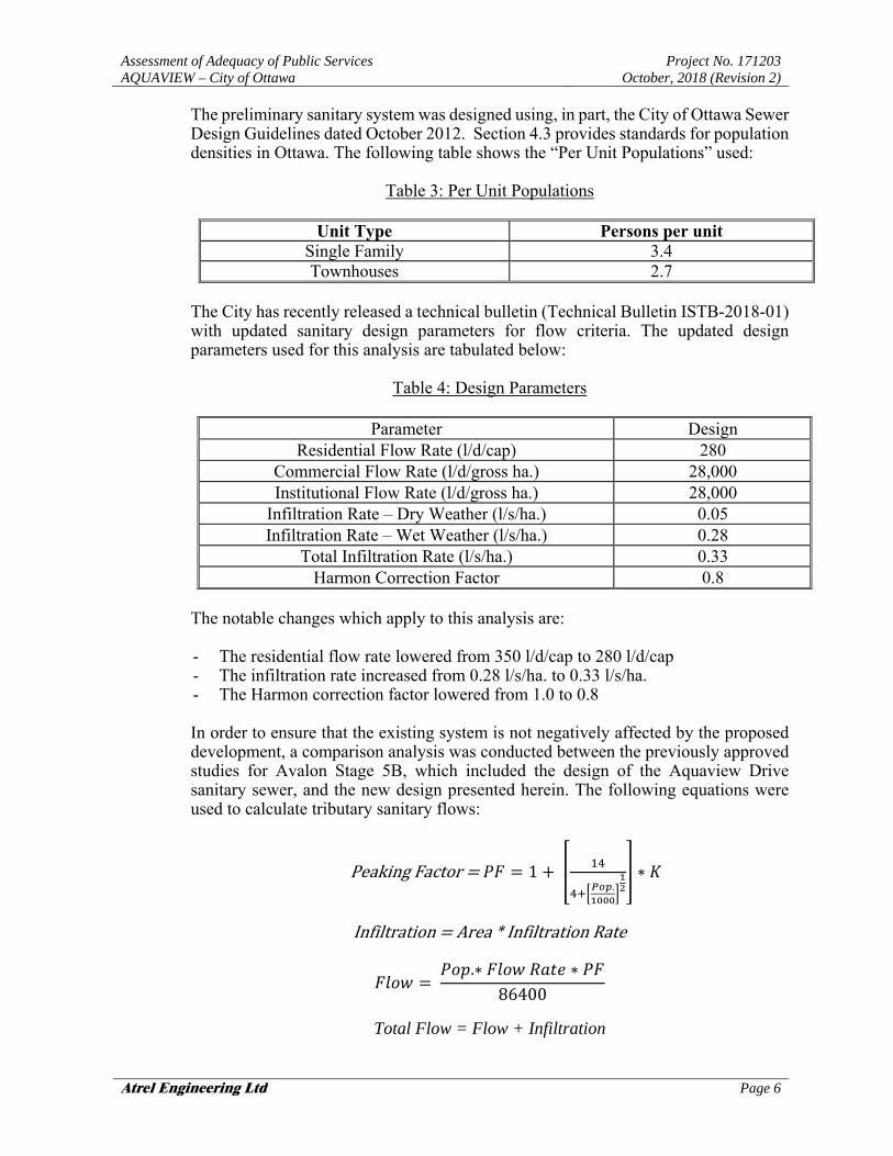
The preliminary sanitary system was designed using, in part, the City of Ottawa Sewer Design Guidelines dated October 2012. Section 4.3 provides standards for population densities in Ottawa. The following table shows the “Per Unit Populations” used:
Table 3: Per Unit Populations
Unit Type Persons per unit
Single Family 3.4 Townhouses 2.7
The City has recently released a technical bulletin (Technical Bulletin ISTB-2018-01) with updated sanitary design parameters for flow criteria. The updated design parameters used for this analysis are tabulated below:
Table 4: Design Parameters
Parameter Design
Residential Flow Rate (l/d/cap) 280 Commercial Flow Rate (l/d/gross ha.) 28,000 Institutional Flow Rate (l/d/gross ha.) 28,000
Infiltration Rate – Dry Weather (l/s/ha.) 0.05 Infiltration Rate – Wet Weather (l/s/ha.) 0.28
Total Infiltration Rate (l/s/ha.) 0.33 Harmon Correction Factor 0.8
The notable changes which apply to this analysis are: - The residential flow rate lowered from 350 l/d/cap to 280 l/d/cap - The infiltration rate increased from 0.28 l/s/ha. to 0.33 l/s/ha. - The Harmon correction factor lowered from 1.0 to 0.8 In order to ensure that the existing system is not negatively affected by the proposed development, a comparison analysis was conducted between the previously approved studies for Avalon Stage 5B, which included the design of the Aquaview Drive sanitary sewer, and the new design presented herein. The following equations were used to calculate tributary sanitary flows:
PeakingFactor 1 .
∗
Infiltration Area*InfiltrationRate
.∗ ∗
86400
Total Flow = Flow + Infiltration
Assessment of Adequacy of Public Services AQUAVIEW – City of Ottawa
Project No. 171203 October, 2018 (Revision 2)
Atrel Engineering Ltd Page 7
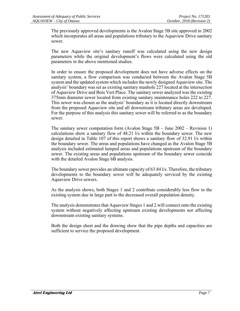
The previously approved developments is the Avalon Stage 5B site approved in 2002 which incorporates all areas and populations tributary to the Aquaview Drive sanitary sewer. The new Aquaview site’s sanitary runoff was calculated using the new design parameters while the original development’s flows were calculated using the old parameters in the above mentioned studies. In order to ensure the proposed development does not have adverse effects on the sanitary system, a flow comparison was conducted between the Avalon Stage 5B system and the updated system which includes the newly designed Aquaview site. The analysis’ boundary was set as existing sanitary manhole 227 located at the intersection of Aquaview Drive and Bois Vert Place. The sanitary sewer analyzed was the existing 375mm diameter sewer located from existing sanitary maintenance holes 222 to 227. This sewer was chosen as the analysis’ boundary as it is located directly downstream from the proposed Aquaview site and all downstream tributary areas are developed. For the purpose of this analysis this sanitary sewer will be referred to as the boundary sewer. The sanitary sewer computation form (Avalon Stage 5B – June 2002 – Revision 1) calculations show a sanitary flow of 48.21 l/s within the boundary sewer. The new design detailed in Table 107 of this report shows a sanitary flow of 32.91 l/s within the boundary sewer. The areas and populations have changed as the Avalon Stage 5B analysis included estimated lumped areas and populations upstream of the boundary sewer. The existing areas and populations upstream of the boundary sewer coincide with the detailed Avalon Stage 6B analysis. The boundary sewer provides an ultimate capacity of 63.84 l/s. Therefore, the tributary developments to the boundary sewer will be adequately serviced by the existing Aquaview Drive sewers. As the analysis shows, both Stages 1 and 2 contribute considerably less flow to the existing system due in large part to the decreased overall population density. The analysis demonstrates that Aquaview Stages 1 and 2 will connect onto the existing system without negatively affecting upstream existing developments nor affecting downstream existing sanitary systems. Both the design sheet and the drawing show that the pipe depths and capacities are sufficient to service the proposed development.

Assessment of Adequacy of Public Services AQUAVIEW – City of Ottawa
Project No. 171203 October, 2018 (Revision 2)
Atrel Engineering Ltd Page 8
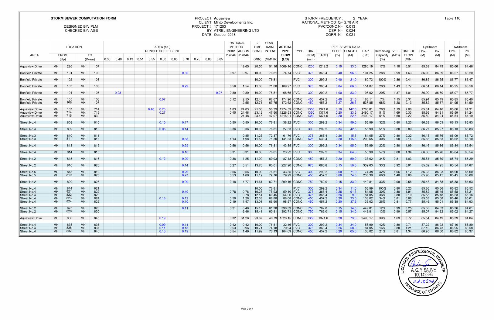
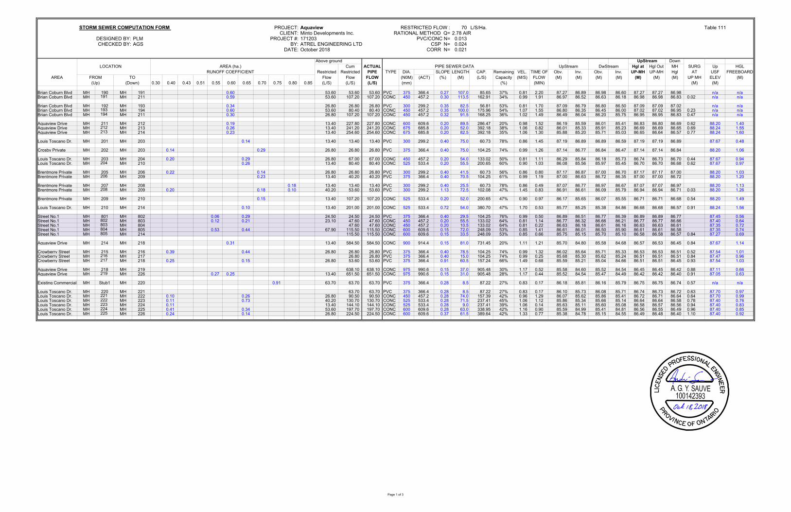
2.5 Storm Sewer
As mentioned, CCL’s report prescribes for the Aquaview development’s storm runoff to be directed to the existing Neighbourhood 2 SWM pond. This existing SWM facility controls for both quantity and quality criteria of the storm water from Neighbourhood 2 and will include the Aquaview development, Stages 1 and 2 (See Appendix ‘F’ – 171203-STMM). The attenuated flow is then discharged via a storm sewer to the Tenth Line Road sewer system. The SWM pond’s 100 year storm event level is 85.90m according to the previously approved studies. Similarly, the hydraulic grade line elevation for the 100 year storm at the existing storm maintenance hole G immediately upstream of the SWM pond is 86.00m. This elevation was used in the storm sewer computation forms presented in Appendix ‘F’. The reference numbers for the Ministry of the Environment Certificates of Approval regarding the existing Stormwater Management Facility and the existing storm sewers of Avalon Stage 5 and 6B, which include the sewers on Aquaview Drive are as followed: - ECA#7205-4JQHFV (Neighbourhood 2 SWM Facility) - ECA#8709-5DHGWX (Avalon Stage 5) - ECA#9730-5Y8KQT (Avalon Stage 6B) The design flows for the current project were calculated using both the 2 & 5 year Intensity Duration Frequency (IDF) curve from the City of Ottawa. The minor drainage systems for stages 1 and 2 of the proposed development were designed to carry a flow equivalent to a 1 in 2 year storm event with a 10 minute inlet time. A flow equivalent to a 1 in 5 year storm and a 20 minute inlet time was used for the existing areas of Avalon Stages 5B and 6B. The resulting computation form detailing the storm sewer system characteristics up to the SWM facility are presented in Appendix ‘F’ (see Table 110). Storm flows for both stages are directly discharged into the existing storm sewers on Aquaview Drive. The main storm drainage design constraints can be summarized as follows:
a) Minor System
1) Inflow rate into the minor system should be limited to 70 l/s/ha, as per CCL’s report.
2) All residential inlets will be equipped with inlet control devices. The term “inlet” means “a single catchbasin” or “a group of interconnected catchbasins” connected by a single lead into the minor system.
3) The hydraulic grade line shall be computed and the maximum permitted hydraulic grade line elevation is to be 0.30m below the underside of footing.

Assessment of Adequacy of Public Services AQUAVIEW – City of Ottawa
Project No. 171203 October, 2018 (Revision 2)
Atrel Engineering Ltd Page 9
b) Major System 1) Grading design is to be based on split lot drainage. 2) On street routing to emergency storage area must be provided and
illustrated on the grade control plan. This routing must incorporate a maximum 0.35m flow depth on street under either static or dynamic conditions. An overall positive slope of 0.10% will be required across consecutive high points for routing purposes.
c) Water Quality
1) An Enhanced Level of Protection (80 % removal of Total Suspended Solids) needs to be achieved in the stormwater management wet pond. The Best Management Practices should also be implemented within the subdivision design and during construction.
A storm sewer computation form details the calculations for the system restricted to a minor system inflow rate of 70 l/s/ha and includes the calculated hydraulic grade line to ensure that a freeboard of 0.30 m is provided within both the proposed and existing developments tributary to the system (see Table 111 in Appendix ‘F’).
The design sheets and the drawing show that the pipe depths and capacities are sufficient to service the proposed developments. The minor system capture rate could be increased during the detailed design process for the proposed development and/or the existing developments in order to increase the level of service and maximize the minor system’s utility. This could be achieved by removing links between existing catchbasins and/or upsizing existing inlet control devices.
Assessment of Adequacy of Public Services AQUAVIEW – City of Ottawa
Project No. 171203 October, 2018 (Revision 2)
Atrel Engineering Ltd Page 10
3.0 CONCLUSION
This report demonstrates that the proposed Aquaview development can be serviced by connecting to the existing sanitary sewers. The storm sewer system will be designed in conformance with the City of Ottawa standards and outlet to the Neighbourhood 2 SWM pond as originally prescribed in CCL’s report. The existing watermain on Aquaview Drive will provide an adequate level of servicing for both water consumption and firefighting purposes. Based on the information provided in this report, the Aquaview development can be serviced to meet the City of Ottawa requirements.
Prepared by:
ATREL ENGINEERING LTD
André Sauvé, P. Eng.

APPENDIX "A"
SK-1 Street Map


APPENDIX "B"
Pre-consultation meeting records

1
Andre Sauve
From: Lebrun, Julie (Planning) <[email protected]>Sent: Tuesday, March 13, 2018 8:16 AMTo: 'Susan Murphy'; 'De Santi, Nadia'Cc: Curry, William; Young, Mark; Wood, Mary Ellen; Yousfani, Asad; Andre Sauve; Harte,
AndrewSubject: Minto Aquaview
Good morning all, As a follow‐up to our pre‐application consultation of Wednesday, February 28th, we would like to provide the following:
‐ Minto is proposing a phased draft plan of subdivision; ‐ One phase is located at 352 Aquaview Drive and is proposing 48 single detached dwellings on a cul‐de‐sac; ‐ The other phase (core block) is located at the intersection of Tenth Line Road, Lakepointe Drive and Aquaview
Drive immediately south of the future Transitway corridor and station; it will contain a mix of rear lane townhomes, back to back townhomes and traditional townhomes on public streets.
Preliminary Comments: Urban Design:
‐ Considering mixing higher density residential with the singles at 352 Aquaview Drive; ‐ In core block, move higher density residential closer to Tenth Line road and adjacent to the future transit
station; ‐ Rear lane, 3 storey townhomes, should be facing Lakepointe Drive and all of Aquaview Drive to provide street
presence across from the pond and help slow down traffic; ‐ Ensure there is a street connection and a MUP along the eastern boundary of the core site to the transitway
lands; this connection was being reserved for an access for buses to the transit corridor and may still be required in the future;
‐ A second pedestrian connection should be located mid‐block to provide a link to the transit corridor to connect to the future extension of the Major Recreational Pathway;
Parks: ‐ Parks will request land dedication of 1.11ha as parkland through the draft plan of subdivision based on the
proposed and existing unit count. The proposal of 322 units plus the existing Neighbourhood 2 unit count of 968 units equal a total of 1290 units. Parkland dedication will be calculated using 1ha/300 dwelling units resulting in a required parkland dedication of 4.3ha. Existing Aquaview Park has an area of 3.19ha.
‐ The layout of Phase 2 to include a 1.11ha Parkette. The Parkette is to be centrally located within the neighbourhood, providing an interesting focal point and contributing to the community character. The Parkette is to be rectangular in shape, to maximize recreational opportunities and located along local roads with a minimum of 50% street frontage. A range of active and passive recreation opportunities shall be proposed within the parkette. Please refer to the Park Development Manual – Second Edition 2017 for more information on Parkette design and requirements.
‐ In addition, please introduce a MUP on the east side of the existing 20m ROW to facilitate a pedestrian connection from Aquaview Drive to the proposed BRT corridor.
‐ A walkway block should be added from Street 14 within Phase 1 to increase pedestrian connectivity. Required Plans, Reports and Studies (Plans 15 copies / Reports 3 copies unless otherwise indicated):
2
Draft Plan of Subdivision Topographical Plan of Survey (2 copies) Planning Rationale (4 copies) Phase 1 Environmental Site Assessment (Phase 2 ESA if required by Phase 1 ESA) Design Brief/Stormwater Management Report complete with Modeling Geotechnical Report Supporting Modeling; Existing Stage 6B with the proposed areas inclusive. Landscape Plan, Details Tree Conservation Report Environmental Impact Statement Archeological Resource Assessment Transportation Impact Study and Road Modification Plan if required Noise and Vibration Study Engineering:
Grading Plan & Drainage Plan General Plan of Services Plan and Profile Plans SWM Plans Erosion & Sediment Control Plan Composite Utility Plan Details/road cross sections
Consultant to Coordinate with the Conservation Authority Consultant to provide Boundary Condition Request
Minimum Drawing and File Requirements‐ All Plans
Plans are to be submitted on standard A1 size (594mm x 841mm) sheets, utilizing an appropriate Metric scale (1:200, 1:250, 1:300, 1:400, or 1:500). With all submitted plans and reports please provide an individual PDF format of the files.
Tree Conservation Report:
1. a Tree Conservation Report (TCR) must be supplied for review along with the suite of other plans/reports
required by the City; an approved TCR is a requirement of Site Plan or Plan of Subdivision approval 2. any removal of privately‐owned trees 10cm or larger in diameter require a tree permit issued under the Urban
Tree Conservation Bylaw; the permit is based on the approved TCR 3. in this case, the TCR may be combined with the EIS 4. the TCR must list all trees on site by species, diameter and health condition. Groupings of trees may be
combined together using averages, and diameter ranges. Note that the TCR must address all trees with a critical root zone that extends into the developable area.
5. If trees are to be removed, the TCR must clearly show where they are and document the reason they can not be retained
6. All retained trees must also be shown and all retained trees within the area impacted by the development process must be protected as per the City guidelines listed on Ottawa.ca
7. Trees with a trunk that crosses/touches a property line are considered co‐owned by both property owners; permission from the adjoining property owner must be obtained prior to the removal of co‐owned trees
8. the City does encourage the retention of healthy trees wherever possible; please ask your design/planning team to find opportunities for retention wherever possible if the trees are healthy and will contribute to the design/function of the site. For more information on the process or help with tree retention options, contact Mark Richardson [email protected]
3
9. the removal of City‐owned trees will require the permission of Forestry Services who will also review the submitted TCR; note that Forestry Services may ask for compensation for any City‐owned tree that has to be removed.
The list of plans and reports noted above is preliminary and therefore the City reserves the right to request additional plans and reports as necessary. Regards, Julie Lebrun, MCIP, RPP (MICU, UPC) Planner / Urbaniste Development Review, Suburban Services East / Examen des demandes d'aménagement, Services suburbains est Planning, Infrastructure and Economic Development / Services de planification, d'infrastructure et de développement économique City of Ottawa | Ville d'Ottawa
613.580.2424 ext./poste 27816 ottawa.ca/planning / ottawa.ca/urbanisme
'
This e-mail originates from the City of Ottawa e-mail system. Any distribution, use or copying of this e-mail or the information it contains by other than the intended recipient(s) is unauthorized. Thank you.
Le présent courriel a été expédié par le système de courriels de la Ville d'Ottawa. Toute distribution, utilisation ou reproduction du courriel ou des renseignements qui s'y trouvent par une personne autre que son destinataire prévu est interdite. Je vous remercie de votre collaboration.
'

APPENDIX "C"
171203-GRM - Macro Grading Plan 171203-ESCM - Macro Erosion and Sediment Control Plan


APPENDIX "D"
171203-WA1 - Watermain Size and Alignment 171203-WA2 - Watermain Layout and Demand Table 101: Node Data Table 102: Pipe Data Table 103: Reservoir Data Table 104: Average Day and Peak Hour Demand Results Table 105: Maximum Day plus Fire-Flow Results Table 106: Fire Flow Calculations E-mail Correspondence with the City of Ottawa – Boundary Conditions


TABLE 101: NODE DATAPROJECT: Aquaview
DATE: October 2018 CLIENT: Minto Communities Inc.
DESIGNED BY: JSG PROJECT #: 171203
CHECKED BY: AGS BY: Atrel Engineering Ltd
Street C.L.NODE. NO. AVERAGE DAY DEMAND Elevation X COORDINATE Y COORDINATE
(l/s) (m) (m) (m)
J140 0.2479 89.35 384616.32 5035419.64
J142 0.0964 89.45 384562.15 5035429.23
J144 0.0826 89.45 384530.39 5035433.17
J146 0.0000 89.45 384555.58 5035425.17
J200 0.0328 89.28 384484.57 5035765.68
J201 0.0766 89.60 384461.08 5035821.04
J202 0.1313 89.75 384432.80 5035876.37
J204 0.1750 89.65 384367.75 5035846.93
J206 0.2078 89.55 384307.60 5035781.72
J208 0.1313 89.65 384265.78 5035722.27
J210 0.1531 89.68 384231.85 5035673.84
J212 0.0656 89.74 384203.52 5035630.96
J214 0.0984 89.60 384238.29 5035543.36
J216 0.1094 89.70 384267.54 5035480.81
J218 0.2953 89.50 384352.73 5035515.64
J220 0.1203 89.45 384351.33 5035590.39
J222 0.0000 89.27 384401.13 5035587.71
J224 0.0438 89.32 384417.43 5035658.95
J226 0.1094 89.40 384436.60 5035722.79
J228 0.1750 89.55 384395.51 5035787.87
J230 0.1531 89.45 384353.67 5035702.52
J232 0.0875 89.50 384330.63 5035581.74
J234 0.2078 89.57 384302.87 5035648.73
J236 0.0984 89.55 384284.45 5035562.57
J238 0.2188 89.62 384262.73 5035614.99
Phase 1
Phase 2

TABLE 102: PIPE DATA PROJECT: Aquaview
DATE: October 2018 CLIENT: Minto Communities Inc.
DESIGNED BY: JSG PROJECT #: 171203
CHECKED BY: AGS BY: Atrel Engineering Ltd
PIPE NO. FROM TO LENGTH INSIDE DIAMETER ROUGHNESS FLOW VELOCITY HEADLOSS HL/1000 FLOW VELOCITY HEADLOSS HL/1000(m) (mm) (L/S) (m/s) (m) (m/km) (L/S) (m/s) (m) (m/km)
P200 RES1000 J200 56.82 297 120 1.3412 0.0194 0.0001 0.0026 -10.7276 0.1548 0.0071 0.1252P202 J201 J202 63.49 204 110 0.3234 0.0099 0.0001 0.0015 -1.4062 0.0430 0.0014 0.0214P204 J202 J204 73.52 204 110 0.1921 0.0059 0.0000 0.0005 -2.1284 0.0651 0.0034 0.0459P206 J204 J206 89.50 204 110 0.2023 0.0062 0.0001 0.0006 -2.6966 0.0825 0.0064 0.0711P208 J206 J208 72.68 204 110 0.2045 0.0063 0.0000 0.0005 -2.5205 0.0771 0.0046 0.0627P210 J208 J234 83.91 204 110 -0.0446 0.0014 0.0000 0.0000 -1.6451 0.0503 0.0024 0.0285P212 J232 J220 22.44 297 120 -0.9349 0.0135 0.0000 0.0012 -8.1930 0.1183 0.0017 0.0763P214 J220 J222 51.01 297 120 -1.3814 0.0199 0.0001 0.0027 -11.2432 0.1623 0.0070 0.1366P216 J200 J226 65.47 297 120 0.9084 0.0131 0.0001 0.0013 -9.9231 0.1432 0.0071 0.1085P218 J208 J210 59.13 204 110 0.1178 0.0036 0.0000 0.0003 -1.5976 0.0489 0.0016 0.0271P220 J210 J212 51.73 204 110 -0.0045 0.0001 0.0000 0.0000 -1.1326 0.0347 0.0007 0.0142P222 J212 J214 94.60 204 110 -0.0701 0.0021 0.0000 0.0001 -1.4934 0.0457 0.0023 0.0238P224 J214 J216 70.22 204 110 0.0785 0.0024 0.0000 0.0001 -0.1626 0.0050 0.0000 0.0004P226 J216 J218 94.13 204 110 -0.0309 0.0009 0.0000 0.0000 -0.7643 0.0234 0.0007 0.0069P228 J234 J232 72.52 204 110 -0.2524 0.0077 0.0001 0.0009 -2.7880 0.0853 0.0055 0.0757P230 J218 J220 76.08 204 110 -0.3262 0.0100 0.0001 0.0015 -2.3885 0.0731 0.0043 0.0569P232 J210 J238 67.93 204 110 -0.0307 0.0009 0.0000 0.0000 -1.3071 0.0400 0.0013 0.0186P234 J238 J236 56.75 204 110 -0.2495 0.0076 0.0001 0.0010 -2.5105 0.0768 0.0035 0.0623P236 J236 J232 50.00 297 120 -0.5950 0.0086 0.0000 0.0006 -4.9237 0.0711 0.0015 0.0296P238 J206 J230 93.82 204 110 -0.2100 0.0064 0.0001 0.0007 -1.3189 0.0404 0.0018 0.0189P240 J230 J224 80.10 204 110 -0.3631 0.0111 0.0001 0.0016 -2.1610 0.0661 0.0038 0.0472P242 J222 RES1002 96.12 297 120 -1.3495 0.0195 0.0003 0.0027 -25.5267 0.3685 0.0600 0.6243P244 J228 J226 79.35 204 110 -0.3601 0.0110 0.0001 0.0018 -1.3569 0.0415 0.0016 0.0199P246 J204 J228 65.45 204 110 -0.1851 0.0057 0.0000 0.0004 -0.3944 0.0121 0.0001 0.0020P248 J224 J222 73.08 297 120 0.0319 0.0005 0.0000 0.0000 -14.2836 0.2062 0.0156 0.2129P250 RES1004 J140 111.04 250 110 0.4269 0.0087 0.0001 0.0008 2.3480 0.0478 0.0023 0.0204P252 J140 J142 58.36 250 110 0.1790 0.0036 0.0000 0.0002 0.9845 0.0201 0.0002 0.0041P254 J142 J146 7.72 250 110 0.0416 0.0008 0.0000 0.0000 0.2289 0.0047 0.0000 0.0000P256 J142 J144 45.81 50 110 0.0410 0.0209 0.0013 0.0288 0.2254 0.1148 0.0310 0.6768P258 J144 J146 37.33 50 100 -0.0416 0.0212 0.0013 0.0354 -0.2289 0.1166 0.0310 0.8304P260 J226 J224 67.39 297 120 0.4389 0.0063 0.0000 0.0004 -11.8816 0.1715 0.0102 0.1514P262 J201 J200 60.14 204 110 -0.4000 0.0122 0.0001 0.0020 0.9850 0.0301 0.0007 0.0110P264 J214 J236 50.00 204 110 -0.2471 0.0076 0.0000 0.0009 -1.8720 0.0573 0.0018 0.0363
Phase 1Phase 2
AVERAGE DAY DEMAND PEAK HOUR DEMAND

TABLE 103: RESERVOIR DATAPROJECT: Aquaview
DATE: October 2018 CLIENT: Minto Communities Inc
DESIGNED BY: JSG PROJECT #: 171203
CHECKED BY: AGS BY: Atrel Engineering Ltd
RESERVOIR NO. X COORDINATE Y COORDINATE AVERAGE DAY MAX DAY 167 MAX DAY 250 MAX DAY 283 PEAK HOUR LOCATION(m) (m) (m) (m) (m) (m) (m) (Road intersection)
RES1000 384541.02 5035759.27 130.20 124.60 121.70 120.20 124.90 Place du Bois VertRES1002 384411.80 5035495.60 130.20 126.10 124.60 123.90 125.00 Lakepointe DriveRES1004 384617.33 5035311.28 130.20 125.90 N/A N/A 124.90 Louis Toscano Drive
Phase 1Phase 2
HEAD

TABLE 104: AVERAGE DAY AND PEAK HOUR DEMAND RESULTS
PROJECT: Aquaview
DATE: October 218 CLIENT: Minto Communities Inc
DESIGNED BY: JSG PROJECT #: 171203
CHECKED BY: AGS BY: Atrel Engineering Ltd
Street C.L.NODE NO. Elevation Demand HGL Pressure Third Floor Demand HGL Pressure Third Floor
(m) (l/s) (m) (kPa) Pressure (kPa) (l/s) (m) (kPa) Pressure (kPa)
J140 89.35 0.2479 130.20 400.30 370.87 1.3635 124.90 348.34 318.91J142 89.45 0.0964 130.20 399.32 369.89 0.5302 124.90 347.36 317.93J144 89.45 0.0826 130.20 399.30 369.87 0.4543 124.87 347.05 317.62J146 89.45 0.0000 130.20 399.32 369.89 0.0000 124.90 347.36 317.93J200 89.28 0.0328 130.20 400.98 371.55 0.1804 124.91 349.12 319.69J201 89.60 0.0766 130.20 397.85 368.42 0.4213 124.91 345.99 316.56J202 89.75 0.1313 130.20 396.37 366.94 0.7222 124.91 344.53 315.10J204 89.65 0.1750 130.20 397.35 367.92 0.9625 124.91 345.54 316.11J206 89.55 0.2078 130.20 398.33 368.90 1.1429 124.92 346.59 317.16J208 89.65 0.1313 130.20 397.35 367.92 0.7222 124.92 345.65 316.22J210 89.68 0.1531 130.20 397.06 367.63 0.8421 124.93 345.37 315.94J212 89.74 0.0656 130.20 396.47 367.04 0.3608 124.93 344.79 315.36J214 89.60 0.0984 130.20 397.84 368.41 0.5412 124.93 346.19 316.76J216 89.70 0.1094 130.20 396.86 367.43 0.6017 124.93 345.21 315.78J218 89.50 0.2953 130.20 398.82 369.39 1.6242 124.93 347.17 317.74J220 89.45 0.1203 130.20 399.31 369.88 0.6617 124.93 347.71 318.28J222 89.27 0.0000 130.20 401.08 371.65 0.0000 124.94 349.54 320.11J224 89.32 0.0438 130.20 400.59 371.16 0.2409 124.92 348.90 319.47J226 89.40 0.1094 130.20 399.81 370.38 0.6017 124.91 348.01 318.58J228 89.55 0.1750 130.20 398.33 368.90 0.9625 124.91 346.53 317.10J230 89.45 0.1531 130.20 399.31 369.88 0.8421 124.92 347.58 318.15J232 89.50 0.0875 130.20 398.82 369.39 0.4813 124.93 347.20 317.77J234 89.57 0.2078 130.20 398.14 368.71 1.1429 124.93 346.46 317.03J236 89.55 0.0984 130.20 398.33 368.90 0.5412 124.93 346.69 317.26J238 89.62 0.2188 130.20 397.65 368.22 1.2034 124.93 345.97 316.54
Phase 1Phase 2
PEAK HOUR DEMANDAVERAGE DAY DEMAND

TABLE 105: MAXIMUM DAY PLUS FIREFLOW RESULTS
PROJECT: Aquaview
DATE: October 2018 CLIENT: Minto Communities Inc.
DESIGNED BY: JSG PROJECT #: 171203
CHECKED BY: AGS BY: Atrel Engineering Ltd
NODE Static Static Static Fire-Flow Residual Available Flow Available Flow Total Available Flow Critical Critical Node Critical Node Adjusted DesignNO. Demand Pressure Head Demand Pressure @ Hydrant Pressure Demand @ Hydrant NODE Pressure Head Available Flow Flow
(L/s) (kPa) (m) (L/s) (kPa) (L/s) (kPa) (L/s) (L/s) ID (kPa) (m) (L/s) (L/s)
J140 0.6198 358.16 125.90 167.00 297.59 335.30 140.0 167.6186 335.30 J144 138.9 103.6 334.42 334.24J142 0.2410 357.18 125.90 167.00 264.99 266.01 140.0 167.2398 266.01 J144 139.9 103.7 265.97 265.74J144 0.2065 357.11 125.89 167.00 -16900.92 15.75 140.0 167.2053 15.75 J144 140.0 103.7 15.75 15.75J146 0.0000 357.18 125.90 167.00 260.85 259.51 140.0 166.9988 259.51 J146 140.0 103.7 259.51 259.51J200 0.0820 322.98 122.24 250.00 312.25 1111.19 140.0 250.0802 1111.19 J200 140.0 103.6 1111.21 1110.72J201 0.1915 321.26 122.38 250.00 231.69 366.00 140.0 250.1897 366.00 J201 140.0 103.9 366.00 366.00J202 0.3283 321.31 122.54 250.00 211.97 329.79 140.0 250.3265 329.79 J202 140.0 104.0 329.79 329.79J204 0.4375 324.10 122.72 250.00 251.75 418.58 140.0 250.4357 418.58 J204 140.0 103.9 418.58 418.58J206 0.5195 328.79 123.10 250.00 258.52 437.39 140.0 250.5177 437.39 J206 140.0 103.8 437.39 437.39J208 0.3283 320.57 122.36 283.00 226.37 414.55 140.0 283.3263 414.55 J208 140.0 103.9 414.55 414.55J210 0.3828 321.28 122.47 283.00 214.00 385.74 140.0 283.3808 385.74 J210 140.0 104.0 385.74 385.74J212 0.1640 320.91 122.49 283.00 168.64 313.24 140.0 283.1620 313.24 J212 140.0 104.0 313.25 313.25J214 0.2460 322.71 122.53 283.00 214.09 384.74 140.0 283.2440 384.74 J214 140.0 103.9 384.74 384.74J216 0.2735 331.46 123.53 250.00 189.03 296.63 140.0 250.2717 296.63 J216 140.0 104.0 296.63 296.63J218 0.7383 333.51 123.53 250.00 201.09 311.66 140.0 250.7365 311.66 J218 140.0 103.8 311.66 311.66J220 0.3008 334.11 123.55 250.00 298.41 686.93 140.0 250.2990 686.93 J220 140.0 103.7 686.93 686.93J222 0.0000 336.23 123.58 250.00 315.25 980.59 140.0 249.9982 980.59 J216 139.3 103.9 978.74 978.74J224 0.1095 331.09 123.11 250.00 309.77 878.20 140.0 250.1077 878.20 J224 140.0 103.6 878.20 878.20J226 0.2735 326.20 122.69 250.00 308.30 911.53 140.0 250.2717 911.53 J226 140.0 103.7 911.54 911.54J228 0.4375 324.91 122.71 250.00 234.33 370.25 140.0 250.4357 370.25 J228 140.0 103.8 370.25 370.25J230 0.3828 329.79 123.10 250.00 229.10 356.68 140.0 250.3810 356.68 J230 140.0 103.7 356.69 356.69J232 0.2188 323.86 122.55 283.00 272.78 613.75 140.0 283.2168 613.75 J232 140.0 103.8 613.76 613.76J234 0.5195 322.30 122.46 283.00 185.42 335.17 140.0 283.5175 335.17 J234 140.0 103.9 335.17 335.17J236 0.2460 323.28 122.54 283.00 259.31 531.70 140.0 283.2440 531.70 J236 140.0 103.8 531.70 531.70J238 0.5470 322.24 122.50 283.00 189.66 341.71 140.0 283.5450 341.71 J238 140.0 103.9 341.71 341.71
Phase 1Phase 2
Yellow shaded cell represents node which will not be subjected to fire flows
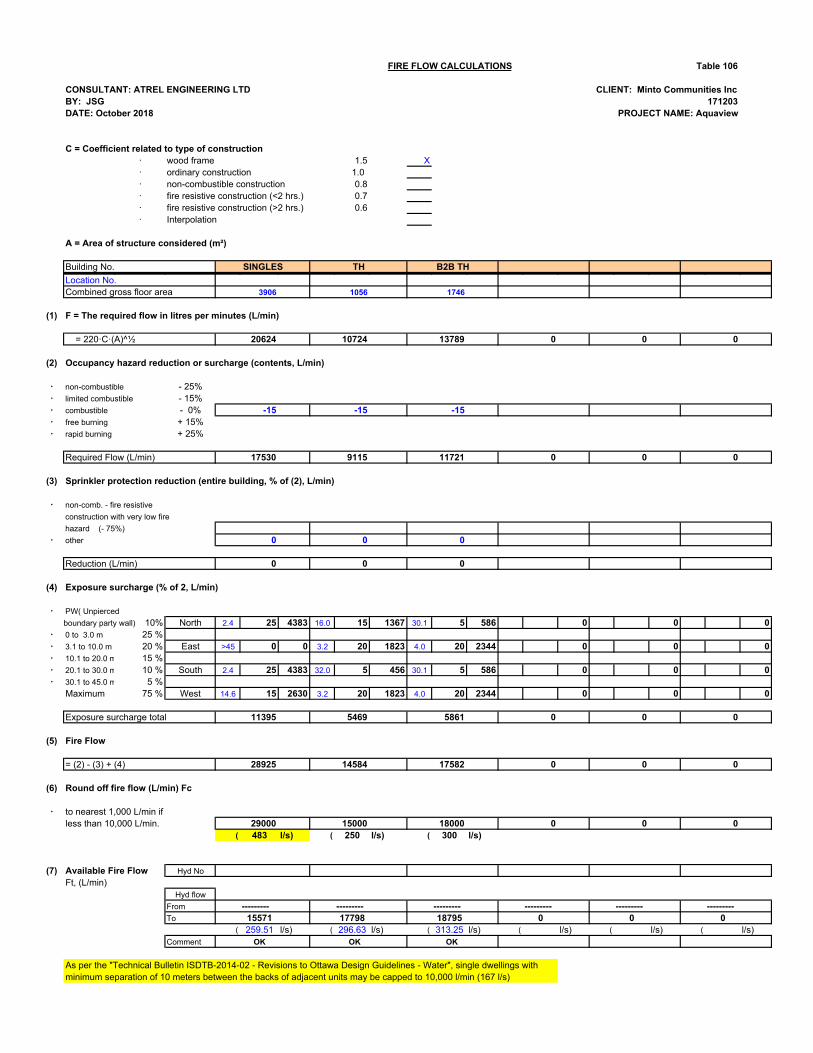
FIRE FLOW CALCULATIONS Table 106
CONSULTANT: ATREL ENGINEERING LTD CLIENT: Minto Communities IncBY: JSG 171203DATE: October 2018 PROJECT NAME: Aquaview
C = Coefficient related to type of construction· wood frame 1.5 X· ordinary construction 1.0· non-combustible construction 0.8· fire resistive construction (<2 hrs.) 0.7· fire resistive construction (>2 hrs.) 0.6· Interpolation
1.5A = Area of structure considered (m²)
Building No.
Location No. ------- - - - - -Combined gross floor area ------- 3906 1056 ------- 1746
(1) F = The required flow in litres per minutes (L/min)
= 220·C·(A)^½ ------- 20624 - 10724 - 13789 0 0 0
(2) Occupancy hazard reduction or surcharge (contents, L/min)
· non-combustible - 25%· limited combustible - 15%· combustible - 0% ------- -15 -15 - -15· free burning + 15%· rapid burning + 25%
Required Flow (L/min) ------- 17530 - 9115 - 11721 0 0 - 0 -
(3) Sprinkler protection reduction (entire building, % of (2), L/min)
· non-comb. - fire resistive
construction with very low fire
hazard (- 75%) ------- - - - - -· other ------- 0 - 0 - 0
Reduction (L/min) ------- 0 - 0 - 0
(4) Exposure surcharge (% of 2, L/min)
· PW( Unpierced
North 2.4 25 4383 16.0 15 1367 30.1 5 586 0 0 0· 0 to 3.0 m 25 %· 3.1 to 10.0 m 20 % East >45 0 0 3.2 20 1823 4.0 20 2344 0 0 0· 10.1 to 20.0 m 15 %· 20.1 to 30.0 m 10 % South 2.4 25 4383 32.0 5 456 30.1 5 586 0 0 0· 30.1 to 45.0 m 5 %
Maximum 75 % West 14.6 15 2630 3.2 20 1823 4.0 20 2344 0 0 0Party wall (PW) - use 1,000 L/min Exposure surcharge total 11395 5469 5861 0 0 0
(5) Fire Flow
= (2) - (3) + (4) ------- 28925 ------- 14584 ------- 17582 ------- 0 ------- 0 ------- 0
(6) Round off fire flow (L/min) Fc
· to nearest 1,000 L/min ifless than 10,000 L/min. 29000 15000 18000 0 0 0
( 483 l/s) ( 250 l/s) ( 300 l/s)
(7) Available Fire Flow Hyd No
Ft, (L/min)Hyd flow
From --------- --------- --------- --------- --------- ---------To 15571 17798 18795 0 0 0
( 259.51 l/s) ( 296.63 l/s) ( 313.25 l/s) ( l/s) ( l/s) ( l/s)Comment OK OK OK
As per the "Technical Bulletin ISDTB-2014-02 - Revisions to Ottawa Design Guidelines - Water", single dwellings withminimum separation of 10 meters between the backs of adjacent units may be capped to 10,000 l/min (167 l/s)
boundary party wall) 10%
SINGLES TH B2B TH

Boundary Conditions for Aquaview
Information Provided: Date provided: March 2018
Aquaview South Demand
Scenario L/min L/s
Average Daily Demand 39.6 0.66
Maximum Daily Demand 99 1.65
Peak Hour 218.4 3.64
Fire Flow Demand 10000 166.67
Aquaview North Demand
Scenario L/min L/s
Average Daily Demand 180 3
Maximum Daily Demand 449.4 7.49
Peak Hour 988.8 16.48
Fire Flow Demand #1 10000 166.67
Fire Flow Demand #2 15000 250
Fire Flow Demand #3 17000 283.33

Location:

Results:
Connection 1 - Place du Bois Vert
Demand Scenario
Head (m) Pressure1 (psi)
Maximum HGL 130.2 58.7
Peak Hour 124.9 51.1
Max Day plus Fire (10,000 l/min) 124.6 50.8
Max Day plus Fire (15,000 l/min) 121.7 46.5
Max Day plus Fire (17,000 l/min) 120.2 44.5
1 Ground Elevation = 88.92 m
Connection 2 - Lakepointe
Demand Scenario
Head (m) Pressure1 (psi)
Maximum HGL 130.2 59.1
Peak Hour 125.0 51.6
Max Day plus Fire (10,000 l/min) 126.1 53.2
Max Day plus Fire (15,000 l/min) 124.6 51.1
Max Day plus Fire (17,000 l/min) 123.9 50.1
1 Ground Elevation = 88.66m
Connection 3 - Louis Toscano Drive
Demand Scenario
Head (m) Pressure1 (psi)
Maximum HGL 130.2 58.6
Peak Hour 124.9 51.1
Max Day plus Fire (10,000 l/min) 125.9 52.5
1 Ground Elevation = 88.98m
Notes:
1) Encourage the use of firewalls to reduce the high requested fire flows to 10,000 l/min for all residential units in the Aquaview development.
2) Demonstrate that the proposed hydrant network can produce flows as high as 17,000 l/min.
Disclaimer The boundary condition information is based on current operation of the city water distribution system. The computer model simulation is based on the best information available at the time. The operation of the water distribution system can change on a regular basis, resulting in a variation in boundary conditions. The physical properties of watermains deteriorate over time, as such must be assumed in the absence of actual field test data. The variation in physical watermain properties can therefore alter the results of the computer model simulation. Fire Flow analysis is a reflection of available flow in the watermain; there may be additional restrictions that occur between the watermain and the hydrant that the model cannot take into account.

APPENDIX "E" Table 107 - Sanitary Sewer Design Sheet – Free Flow Design Condition 171203-SANM - Macro Sanitary Drainage Area Plan


APPENDIX "F"
Table 110 - Storm Sewer Design Sheet (2 year) Table 111 - Storm Sewer Design Sheet (70 L/s/ha.) 171203 - STMM - Macro Storm Drainage Area Plan


APPENDIX "G"
Development Servicing Study Checklist

Development Servicing Study Checklist
The following section describes the checklist of the required content of servicing studies. It is expected that the proponent will address each one of the following items for the study to be deemed complete and ready for review by City of Ottawa Infrastructure Approvals staff.
The level of required detail in the Servicing Study will increase depending on the type of application. For example, for Official Plan amendments and re-zoning applications, the main issues will be to determine the capacity requirements for the proposed change in land use and confirm this against the existing capacity constraint, and to define the solutions, phasing of works and the financing of works to address the capacity constraint. For subdivisions and site plans, the above will be required with additional detailed information supporting the servicing within the development boundary.
4.1 General Content Section Comments
Executive Summary (for larger reports only). N/A
Date and revision number of the report. Cover Page
Location map and plan showing municipal address, boundary, and layout of proposed development.
1.1 App.“A”
Figure 1, SK-1
Plan showing the site and location of all existing services.
App.“D” App.“E” App.“F”
Drawing 171203-STMM, 171203-SANM, 171203-WA1 and 171203-WA2
Development statistics, land use, density, adherence to zoning and official plan, and reference to applicable subwatershed and watershed plans that provide context to which individual developments must adhere.
1.2
Cumming Cockburn Limited report titled “SWM Plan Neighbourhood 2 – Upper Billberry Creek Watershed – East Urban Community Exapansion Area – February 2000”
Summary of Pre-consultation Meetings with City and other approval agencies.
1.6 App.“B”
Reference and confirm conformance to higher level studies and reports (Master Servicing Studies, Environmental Assessments, Community Design Plans), or in the case where it is not in conformance, the proponent must provide justification and develop a defendable design criteria.
1.2
Cumming Cockburn Limited report titled “SWM Plan Neighbourhood 2 – Upper Billberry Creek Watershed – East Urban Community Exapansion Area – February 2000” Atrel’s report titled “Design Brief - Stage 1 – Sewer Outlets and Master Plans – Revision 2”
Statement of objectives and servicing criteria. 1.1
Identification of existing and proposed infrastructure available in the immediate area. 1.3 Atrel’s Drawings
Identification of Environmentally Significant Areas, watercourses and Municipal Drains potentially impacted by the proposed development (Reference can be made to the Natural Heritage Studies, if available).
2.6 Cumming Cockburn Limited report titled “SWM Plan Neighbourhood 2 – Upper Billberry Creek Watershed – East Urban Community Exapansion Area – February 2000”
Concept level master grading plan to confirm existing and proposed grades in the development. This is required to confirm the feasibility of proposed stormwater management and drainage, soil removal and fill constraints, and potential impacts to neighbouring properties. This is also required to confirm that the proposed grading will not impede existing major system flow paths.
2.1
Identification of potential impacts of proposed piped services on private services (such as wells and septic fields on adjacent lands) and mitigation required to address potential impacts.
N/A
Proposed phasing of the development, if applicable. N/A
Reference to geotechnical studies and recommendations concerning servicing. 2.1 Paterson Group Geotechnical Investigation

All preliminary and formal site plan submissions should have the following information:
App.“C”App.“D” App.“E” App.“F”
Atrel’s Drawings
X Metric scale X North arrow (including construction North)X Key plan
X Name and contact information of applicant and property owner
X Property limits including bearings and dimensions By OLS X Existing and proposed structures and parking areasX Easements, road widening and rights-of-way X Adjacent street name
4.2 Development Servicing Report: Water Section Comments
Confirm consistency with Master Servicing Study, if applicable.
1.2
Availability of public infrastructure to service proposed development
1.3
Identification of system constraints 2.3
Identify boundary conditions 2.3
Confirmation of adequate domestic supply and pressure 2.3
Confirmation of adequate fire flow protection and confirmation that fire flow is calculated as per the Fire Underwriter’s Survey. Output should show available fire flow at locations throughout the development.
2.3.1
Provide a check of high pressures. If pressure is found to be high, an assessment is required to confirm the application of pressure reducing valves.
2.3
Definition of phasing constraints. Hydraulic modeling is required to confirm servicing for all defined phases of the project including the ultimate design
2.3
Address reliability requirements such as appropriate location of shut-off valves
2.3
Check on the necessity of a pressure zone boundary modification.
N/A
Reference to water supply analysis to show that major infrastructure is capable of delivering sufficient water for the proposed land use. This includes data that shows that the expected demands under average day, peak hour and fire flow conditions provide water within the required pressure range
2.3
Description of the proposed water distribution network, including locations of proposed connections to the existing system, provisions for necessary looping, and appurtenances (valves, pressure reducing valves, valve chambers, and fire hydrants) including special metering provisions.
2.3 App.“D”
Description of off-site required feedermains, booster pumping stations, and other water infrastructure that will be ultimately required to service proposed development, including financing, interim facilities, and timing of implementation.
N/A
Confirmation that water demands are calculated based on the City of Ottawa Design Guidelines.
2.3
Provision of a model schematic showing the boundary conditions locations, streets, parcels, and building locations for reference.
2.3 App.“D”

4.3 Development Servicing Report: Wastewater
Section Comments
Summary of proposed design criteria (Note: Wet-weather flow criteria should not deviate from the City of Ottawa Sewer Design Guidelines. Monitored flow data from relatively new infrastructure cannot be used to justify capacity requirements for proposed infrastructure).
2.4
Confirm consistency with Master Servicing Study and/or justifications for deviations.
2.4
Consideration of local conditions that may contribute to extraneous flows that are higher than the recommended flows in the guidelines. This includes groundwater and soil conditions, and age and condition of sewers.
N/A
Description of existing sanitary sewer available for discharge of wastewater from proposed development.
1.3 & 2.4
Verify available capacity in downstream sanitary sewer and/or identification of upgrades necessary to service the proposed development. (Reference can be made to previously completed Master Servicing Study if applicable)
2.4
Calculations related to dry-weather and wet-weather flow rates from the development in standard MOE sanitary sewer design table (Appendix ‘C’) format.
2.4 App.“E”
Description of proposed sewer network including sewers, pumping stations, and forcemains.
2.4App.“E” Atrel’s Drawings
Discussion of previously identified environmental constraints and impact on servicing (environmental constraints are related to limitations imposed on the development in order to preserve the physical condition of watercourses, vegetation, soil cover, as well as protecting against water quantity and quality).
N/A
Pumping stations: impacts of proposed development on existing pumping stations or requirements for new pumping station to service development.
2.4
Forcemain capacity in terms of operational redundancy, surge pressure and maximum flow velocity.
N/A
Identification and implementation of the emergency overflow from sanitary pumping stations in relation to the hydraulic grade line to protect against basement flooding.
2.5
Special considerations such as contamination, corrosive environment etc.
N/A
4.4 Development Servicing Report: Stormwater
Section Comments
Description of drainage outlets and downstream constraints including legality of outlets (i.e. municipal drain, right-of-way, watercourse, or private property)
2.6 Cumming Cockburn Limited report titled “SWM Plan Neighbourhood 2 – Upper Billberry Creek Watershed – East Urban Community Exapansion Area – February 2000”
Analysis of available capacity in existing public infrastructure.
2.6
A drawing showing the subject lands, its surroundings, the receiving watercourse, existing drainage patterns, and proposed drainage pattern.
App.“F” 171203-STMM
Water quantity control objective (e.g. controlling post-development peak flows to pre-development level for storm events ranging from the 2 or 5 year event (dependent on the receiving sewer design) to 100 year return period); if other objectives are being applied, a rationale must be included with reference to hydrologic analyses of the potentially affected subwatersheds, taking into account long-term cumulative effects.
2.6 SWM is existing.
Water Quality control objective (basic, normal or enhanced level of protection based on the sensitivities of the receiving watercourse) and storage requirements.
2.6
Description of the stormwater management concept with facility locations and descriptions with references and supporting information.
2.6

Set-back from private sewage disposal systems. N/A
Watercourse and hazard lands setbacks. N/A
Record of pre-consultation with the Ontario Ministry of Environment and the Conservation Authority that has jurisdiction on the affected watershed.
N/A
Confirm consistency with sub-watershed and Master Servicing Study, if applicable study exists.
2.6
Storage requirements (complete with calculations) and conveyance capacity for minor events (1:5 year return period) and major events (1:100 year return period).
2.6 Cumming Cockburn Limited report titled “SWM Plan Neighbourhood 2 – Upper Billberry Creek Watershed – East Urban Community Exapansion Area – February 2000
Identification of watercourses within the proposed development and how watercourses will be protected, or, if necessary, altered by the proposed development with applicable approvals.
N/A
Calculate pre and post development peak flow rates including a description of existing site conditions and proposed impervious areas and drainage catchments in comparison to existing conditions.
N/A Cumming Cockburn Limited report titled “SWM Plan Neighbourhood 2 – Upper Billberry Creek Watershed – East Urban Community Exapansion Area – February 2000
Any proposed diversion of drainage catchment areas from one outlet to another.
N/A
Proposed minor and major systems including locations and sizes of stormwater trunk sewers, and stormwater management facilities.
2.6 App.“F”
If quantity control is not proposed, demonstration that downstream system has adequate capacity for the post-development flows up to and including the 100 year return period storm event.
N/A
Identification of potential impacts to receiving watercourses
N/A
Identification of municipal drains and related approval requirements.
N/A
Descriptions of how the conveyance and storage capacity will be achieved for the development.
2.6
100 year flood levels and major flow routing to protect proposed development from flooding for establishing minimum building elevations (MBE) and overall grading.
2.6
Inclusion of hydraulic analysis including hydraulic grade line elevations.
2.6 & App.“F”
Description of approach to erosion and sediment control during construction for the protection of receiving watercourse or drainage corridors.
2.2
Identification of floodplains – proponent to obtain relevant floodplain information from the appropriate Conservation Authority. The proponent may be required to delineate floodplain elevations to the satisfaction of the Conservation Authority if such information is not available or if information does not match current conditions.
N/A
Identification of fill constraints related to floodplain and geotechnical investigation.
2.1 Paterson Group Geotechnical Investigation

4.5 Approval and Permit Requirements Section Comments The Servicing Study shall provide a list of applicable permits and regulatory approvals necessary for the proposed development as well as the relevant issues affecting each approval. The approval and permitting shall include but not be limited to the following:
Conservation Authority as the designated approval agency for modification of floodplain, potential impact on fish habitat, proposed works in or adjacent to a watercourse, cut/fill permits and Approval under Lakes and Rivers Improvement Act. The Conservation Authority is not the approval authority for the Lakes and Rivers Improvement Act. Where there are Conservation Authority regulations in place, approval under the Lakes and Rivers Improvement Act is not required, except in cases of dams as defined in the Act.
1.5
Application for Certificate of Approval (CofA) under the Ontario Water Resources Act.
1.5 Will be submitted later
Changes to Municipal Drains. N/A
Other permits (National Capital Commission, Parks Canada, Public Works and Government Services Canada, Ministry of Transportation etc.)
N/A
4.6 Conclusion Section Comments
Clearly stated conclusions and recommendations 3.0
Comments received from review agencies including the City of Ottawa and information on how the comments were addressed. Final sign-off from the responsible reviewing agency.
All draft and final reports shall be signed and stamped by a professional Engineer registered in Ontario
3.0
The Servicing Study shall provide a list of applicable permits and regulatory approvals necessary for the proposed development as well as the relevant issues affecting each approval. The approval and permitting shall include but not be limited to the following: