ER Model Transformation Using Conceptual Modelling …conceptual modeling using DLs. ... denote...
8
IJSRSET1622382 | Received : 20 April 2016 | Accepted : 30 April 2016 | March-April 2016 [(2)2: 1094-1101] © 2016 IJSRSET | Volume 2 | Issue 2 | Print ISSN : 2395-1990 | Online ISSN : 2394-4099 Themed Section: Engineering and Technology 1094 ER Model Transformation Using Conceptual Modelling With Description Logic Vandana M. Patil Research Scholar, Department of Information Technology, R. C. Patel Institute of Technology, Shirpur, Maharashtra, India ABSTRACT Description logic (DL) is a language for knowledge representation which is used to represent the terminological knowledge of an application domain in a structured and well-understood way. Two important features of DL are expressivity and decidability. Description Logics use two types of data structures for representing knowledge viz T-Box and A-Box. T-Box stores the basic terminologies of the application domain whereas A-Box consists of the assertions resulted from inference. Description Logics use two types of inference patterns: classification of individuals and classification of concepts. The process of inference is called as Reasoning. There are several types of reasoning. The reasoning procedures used in DL are Decision Procedures. The purpose of this paper is to understand the basic issues involved in conceptual modeling using DLs. We briefly review the basics of DL along with its architecture, syntax and semantics of DL. Then we will see how we can model a real world application using DL at conceptual level. Keywords: Description Logics, knowledge representation language, reasoning, decision procedures Introduction I. INTRODUCTION A. Knowledge Representation Knowledge representation is crucial in AI. This is because problem solving using AI requires lots of knowledge. Efficiency of problem solving depends upon how the knowledge is represented and manipulated. Knowledge must be represented efficiently, and in a meaningful way because it would be impossible (or at least impractical) to explicitly represent every fact that may be needed. The knowledge should be represented such as new facts can be inferred properly from existing knowledge. However, the representation language should achieve a tradeoff between inferential power (what we can infer) and inferential efficiency (how quickly we can infer it). KR languages features- o It should allow to express knowledge o It should support inference o It should have clear, well defined syntax and semantics. o The representation language should achieve a tradeoff between inferential power (what we can infer) and inferential efficiency (how quickly we can infer it) [1]. B. Description Logic Description Logic is a knowledge representation language which allows the structural representation of the given knowledge with all the desired features listed above alongwith high expressivity and decidability. It allows user to represent queries in very effective way since it has very easy and simple syntax. It also provides many advantages over conventional languages. Hence it is very interesting to learn such language and to model some applications using it [1,2]. DL uses two types of inference patterns 1. Classification of individuals 2. Classification of concepts
Transcript of ER Model Transformation Using Conceptual Modelling …conceptual modeling using DLs. ... denote...
IJSRSET1622382 | Received : 20 April 2016 | Accepted : 30 April 2016 | March-April 2016 [(2)2: 1094-1101]
© 2016 IJSRSET | Volume 2 | Issue 2 | Print ISSN : 2395-1990 | Online ISSN : 2394-4099 Themed Section: Engineering and Technology
1094
ER Model Transformation Using Conceptual Modelling With Description Logic
Vandana M. Patil
Research Scholar, Department of Information Technology, R. C. Patel Institute of Technology, Shirpur, Maharashtra, India
ABSTRACT
Description logic (DL) is a language for knowledge representation which is used to represent the
terminological knowledge of an application domain in a structured and well-understood way. Two
important features of DL are expressivity and decidability. Description Logics use two types of data
structures for representing knowledge viz T-Box and A-Box. T-Box stores the basic terminologies of the
application domain whereas A-Box consists of the assertions resulted from inference. Description Logics
use two types of inference patterns: classification of individuals and classification of concepts. The process
of inference is called as Reasoning. There are several types of reasoning. The reasoning procedures used in
DL are Decision Procedures. The purpose of this paper is to understand the basic issues involved in
conceptual modeling using DLs. We briefly review the basics of DL along with its architecture, syntax and
semantics of DL. Then we will see how we can model a real world application using DL at conceptual
level.
Keywords: Description Logics, knowledge representation language, reasoning, decision procedures
Introduction
I. INTRODUCTION
A. Knowledge Representation
Knowledge representation is crucial in AI. This is
because problem solving using AI requires lots of
knowledge. Efficiency of problem solving depends upon
how the knowledge is represented and manipulated.
Knowledge must be represented efficiently, and in a
meaningful way because it would be impossible (or at
least impractical) to explicitly represent every fact that
may be needed. The knowledge should be represented
such as new facts can be inferred properly from existing
knowledge. However, the representation language
should achieve a tradeoff between inferential power
(what we can infer) and inferential efficiency (how
quickly we can infer it).
KR languages features-
o It should allow to express knowledge
o It should support inference
o It should have clear, well defined syntax and
semantics.
o The representation language should achieve a
tradeoff between inferential power (what we can
infer) and inferential efficiency (how quickly we
can infer it) [1].
B. Description Logic
Description Logic is a knowledge representation
language which allows the structural representation of
the given knowledge with all the desired features listed
above alongwith high expressivity and decidability. It
allows user to represent queries in very effective way
since it has very easy and simple syntax. It also provides
many advantages over conventional languages. Hence it
is very interesting to learn such language and to model
some applications using it [1,2].
DL uses two types of inference patterns
1. Classification of individuals
2. Classification of concepts
International Journal of Scientific Research in Science, Engineering and Technology (ijsrset.com)
1095
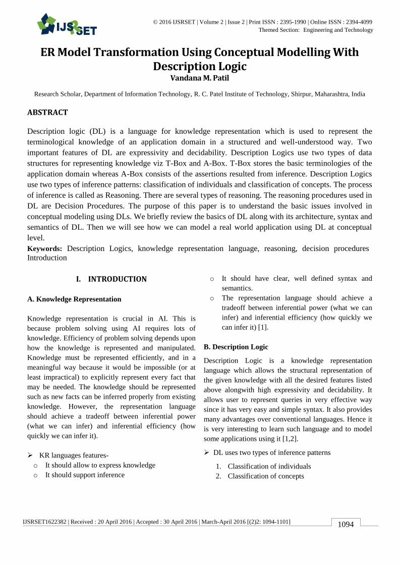
Figure 1. Classification of individuals
An example of network representation
C. Syntax of DL
Syntax refers to rules for writing sentences in a
language.
The syntax of DL consists of -
A set of unary predicates symbols which
denote concept names.
A set of binary relation or predicates which
denote role names.
A recursive definition for defining concept terms
from concept name and role names using
constructors.
D. Semantics in DL
Semantics are defined by interpreting concepts as set
of individuals and roles as pair of
individuals.Semantics of non-atomic concepts and
roles are defined in terms of atomic concepts and
atomic roles respectively using recursive
definition.Semantics is given by means of
interpretation I that consists of a non-empty set ∆I
(the domain of interpretation) and an interpretation
function(.I) which assigns to every atomic concept A
a set AI ∆I and every atomic role R a binary
relation RI ∆I [1].
E. Notations in DL
A, B - atomic concepts
C, D - concept description
R, S - roles and
f, g - attributes
m, n - non-negative integers individuals are denoted by
letters a, b. This convention is followed when
defining syntax and semantics and in abstract
examples. In concrete examples following
conventions are used:
1) Concept names start with an uppercase letters
followed by lowercase letters e.g. Human, Male.
2) Role names start with lowercase letters
e.g. hasChild,marriedTo.
3) Individual names are all uppercase. e.g. CHARLES,
MARY.
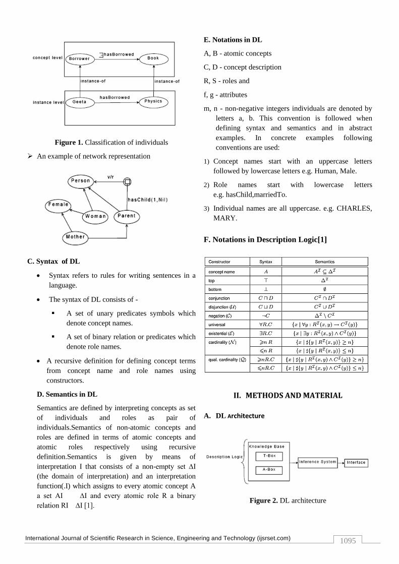
F. Notations in Description Logic[1]
II. METHODS AND MATERIAL
A. DL Architecture
Figure 2. DL architecture

International Journal of Scientific Research in Science, Engineering and Technology (ijsrset.com)
1096
DL knowledge base consists of two components [1,3]:
1. T-Box : A set of terminological axioms.
2. A-Box : A set of assertional axioms
1. T-Box
Set of terminological axioms
Terminological axioms are of two types-
o Inclusion axioms e.g. C D
o Equality axioms e.g. C ≡ D
2. A-Box
Set of assertions
Two types of assertions-
o Concept assertions: Given as C(a) i.e.a
belongs to C.e.g. Book(Computer
Basics)
o Role assertions :Given as R(b,c) i.e.
which states that c is the filler of role R
for b.e.g. hasManager(John,Steve)
B. Conceptual Modeling
“Conceptual Models” offer more expressive facilities for
modeling applications directly and naturally, and for
structuring information bases. The conceptual model
contains a formal description of the concepts, the
relationship between concepts, and information
requirements. Conceptual Models play an important role
in variety of areas viz
Artificial Intelligence It requires the conceptual
models built up using some knowledge representation
language to represent the human knowledge to work
intelligently.
Database System design It uses the conceptual
models as its initial phase of development which
determines the information needs of users and then
further converted into physical implementation
schema. e.g. ER models.
Software Development In this, requirements model is
used as during the initial requirements acquisition
stage. This model describes the relationship of the
proposed system and its environment. Here the
environment is the conceptual model.
OOMD In this, the software
components(classes/objects) are viewed as models of
the real world entities.
One important aspect of conceptual modeling is the
identification of “Abstraction mechanisms” which
allows development of large models by abstracting
details initially and then introducing them in stepwise
and systematic manner. The abstraction mechanisms
are-
Aggregation Thinking of objects as wholes, not just a
collection of their attributes.
Classification Abstracting away the detailed differences
between individuals, so that a class can represent the
commonalities.
Generalization Abstracting the commonalities of
several classes into a superclass.
An important benefit of abstraction in conceptual
modeling is that it results in structured information
model which is easy to build and maintain [4].
1. Conceptual Modeling with DL
Conceptual Modeling Methodology
Main steps of modeling are-
• Identify the individuals in the desired application
domain.
• Enumerate concepts that group these values.
• Distinguish independent concepts from relationship-
roles.
• Develop a taxonomy of concepts.
• Identify each individual which are of interest in all
states of the application domain.
• Systematically search for part-whole relationship
between objects, creating roles for them.
• Identify other properties of objects and then general
relationships in which they participate.
• Determine local constraints involving roles such as
cardinality constraints and value restrictions.
• Determine more general constraints on relationships
such as those which can be modeled by sub-roles.
• Distinguish essential from incidental properties of
concepts as well as primitive from defined concepts
[1,4]
2. Elementary Description Logic Modeling
Conceptual Modeling using DL uses the object centered
view of the world where each real time entity is viewed
as individual object, object with commanalities are
grouped into classes and objects are related with each
other through relationships. In DL, the classes are
modeled as „Concepts‟ and binary relationships are
modeled as „Roles‟ and „Attributes‟. For every
application domain, there are some obvious classes are
International Journal of Scientific Research in Science, Engineering and Technology (ijsrset.com)
1097
there. These classes are modeled as primitive or atomic
Concepts in DL. Some classes are derived from base
classes i.e. inherited. The inheritance is modeled using
the “Subsumption Relationship” between the classes.
The base class is called as „Subsumer‟ and the derived
class is called as „Subsumee‟. The subsumption is the
basic inference on concepts in DL and is given by- C ⊑
D
The derived classes are modeled as defined concepts and
are defined using the concept definition. The concept
definition specifies the necessary and sufficient
conditions for concept membership.
e.g.-Mother ≡ Woman ⊓∃ hasChild.Person
The subsumption is given as-
Mother ⊑ Woman
Besides this,there are other operators in DL which are
very useful to capture the important aspects of the
subclass relationships among the object in the UoD.
Those are given below:
1. Disjunction operator
2. Conjunction operator
3. Negation operator
Negation operator It is used to model the disjoint
subclasses. It is useful when the superclass is specialized
into its subclasses in such a way that the subclasses are
totally disjoint. e.g. Superclass Person is specialized into
two disjoint subclasses such as Male and Female.
Male ≡ ¬ Female
Disjunction operator It is used to model the
relationship between the disjoint subclasses which fully
covers the superclass. e.g. going with the same example
given above, we can represent the superclass as
disjunction of the two disjoint subclasses-
Person ≡ Male ⊔ Female
Conjunction operator It is used to model the
combination of two expressions into single
expression.e.g if we want to define the conceptWoman,
we have to specify two conditions i.e. Person and
Female. This is written in DL as-
Woman ⊑ Person ⊓ Female
Concept Constructors
The things,like kinds of values that can fill roles, and
limit on the number of role fillers, are modeled via
concept constructors in DL. The concept constructors
are as follows-
• the
• all
• at-most
• at-least
• same as
• non-overlapping
• test
• counting
1. the specifies that the attribute has one and only one
value.
e.g. isbnNr
2. all specifies that all individuals should satisfy the
given condition.
e.g. Human≡ Animal ⊓ all hasParent Human
3. at-most specifies the maximum value allowed for the
given attribute.
e.g. Mother1≡Mother⊓ at-most 3 hasChild
4. at-least specifies the minimum value allowed for the
given attribute.
e.g. Borrower ≡ all hasBorrowed Book ⊓ at-
least 1 hasBorrowed.
5. same as specifies that two roles have the same value.
e.g same as principal univBOS
6. test is used to check the valid states of the world.
e.g test(date-after(dueDate issueDate) will
invoke the function date-after on the passed attributes
and check that the first is after the second or not.
Support for enumeration
We can define enumerated set of value for a attribute of
a concept using the constructor the and one-of.
e.g. Book ⊑ (the section(one-of ‟student ‟reference))
Then we can define corresponding subconcepts as
follows:
ReferenceBook≡Book⊓ (fills section ‟reference)
Book1≡Book⊓ (fills section ‟section)
Modeling Relationships
Binary relationships are modeled using roles and
attributes. There are a number of special constraints on
relationships such as : cardinality constraints state the

International Journal of Scientific Research in Science, Engineering and Technology (ijsrset.com)
1098
maximum and minimum number of objects that can be
related via a role, domain constraints state the kinds of
objects that can be related via a role and inverse
relationships between roles. These things are modeled in
DL using the role constructors. Cardinality constraints
are modeled using the role constructors such as the,at-
most,at-least,all. Domain constraints are modeled via the
role constructor the and all. Inverse relationships are
modeled using the role constructor inverse.
e.g.
• Borrower ≡ (and(all hasBorrowed Book)(at-most 2
hasBorrowed))
• Mother ≡ (and Woman (at-least 1 hasChild))
• Book ≡ (and (the hasTitle String) (all hasAuthor
Person))
• lentTo≡ ¬ hasBorrowed
Views
The views can even be maintained in DL. This is done
by defining a new concept
which will have some attributes to specify the view. e.g.
a view MaterialOnLoan
will have the attribute such as dueDate and
nrOfRenewals [1,3,4].
C. ER Modeling and Description Logic
In this section, first ER models are introduced shortly,
then transformation of ER schemas into DL knowledge
bases is visited.
1. ER Models
ER model is the most commonly used data model for
pictorial representation of the databases. The basic
elements of the ER model are the entities, relationships
and attributes. An entity denotes a set of objects, called
as instances, which have common properties.
Elementary properties are modeled through attributes,
whose values belong to one of the predefined domains
such string, integer etc. Properties that are due to the
relations to other entities are modeled through the
participation of the entity in relationship. A relation
denotes a set of instances, each of which represents an
association among different entities.
Specialization
An entity B is said to be a specialization of other entity
A, if all instances of B are also instances of A but vice
versa is not true. This situation is modeled through IS-A
relationship in ER models. Relationships can be related
via IS-A. This induces an inheritance of attributes of an
entity to its subentities, and of roles to its subroles.
Cardinality Constraints
Cardinality constraints are used to an ER model to
specify the number of times each instance of an entity is
participating in the relationship. Such constraints are
used in restricted form, where the minimum cardinality
is either 1 or 0 and the maximum cardinality is either 1
or ∞.
2. Formal description of ER schema
An ER schema S is constructed with disjoint sets of
entity symbols, relationship symbols, ER-role symbols,
attribute symbols and domain symbols. Each domain D
has an associated predefined basic domain DBD. For
each entity symbol, a set of attribute symbols is defined,
and to each such a attribute a unique domain symbol is
associated. A relationship symbol of arity n has n
associated ER-role symbols, each with an associated
entity symbol, and defines a relationship between these
entities. The cardinality constraints are represented by
two functions cmin S and cmaxS. IS-A relationship
between entities and between relationships are modeled
by means of binary relations ≼S. The semantics of an
ER schema can be given by specifying which database
states are consistent with the information structure
represented by the schema. Formally a database state B
corresponding to an ER Schema S is constituted by a
nonempty finite set △B,assumed to be disjoint from all
basic domains, and a function ·B that maps-
• every domain symbol D to the corresponding basic
domain DBD.
• every entity E to a subset EB of △B
• every attribute A to a set EB ⊆ △B × ∪D2DS DBD.
• every relationship R to a set RB of labeled tuples
over △B.
International Journal of Scientific Research in Science, Engineering and Technology (ijsrset.com)
1099
C. Transforming ER schemas into DL knowledge
base
The transformation of ER schemas to DL knowledge
base is achieved by defining a translation function Φ and
then establishing correspondence between legal database
states and models of the derived knowledge base. The
knowledge base Φ(S) derived from ER schema S is
defined as follows:
• The set of atomic concepts of Φ(S) consists of the
set of entity and domain symbols in S.
• The set of atomic relation of Φ(S) is obtained from
the set of relationship and attribute symbols in S.
More specifically-
– each symbol R in S, denoting a relation of arity n,
is mapped into a symbol PR in Φ(S), denoting a
relation of arity n.
– each attribute symbol A in S is mapped into a
symbol PA in Φ(S), denoting a relation of arity 2.
Thus, each instance of the relation PA is a tuple such
that its first component corresponds to an entity,
while the second component denotes an element of
the concept corresponding to the attribute domain.
• The set of inclusion axioms of Φ(S) consists of the
following elements:
– for each pair of entities E1, E2 such that E1 ≼S E2,
the inclusion axiom E1 ⊑ E2
– for each pair of entities R1, R2 such that R1 ≼S
R2, the inclusion axiom PR1 ⊑ PR2
– for each attribute A with domain D of entity E, the
inclusion axiom E ⊑ (∀[$1](PA⊓
($2:D)))⊓=1[$1]PA
– for each relationship R of arity n with ER-roles
U1,......,Un in which each Ui is associated with the
entity Ei, the inclusion axiom PR ⊑
( $ R(U1):E1)⊓.....⊓($ R(Un):En)
– for each ER role U of relationship R associated
with entity E, with cardinality constraints m =
cminS(U) and n= cmaxS(U),
∗ if m , the inclusion axiom E ⊑≥ m[$ R(U)]PR
∗ if n ∞, the inclusion axiom E ⊑≤ n[$ R(U)]PR [1].
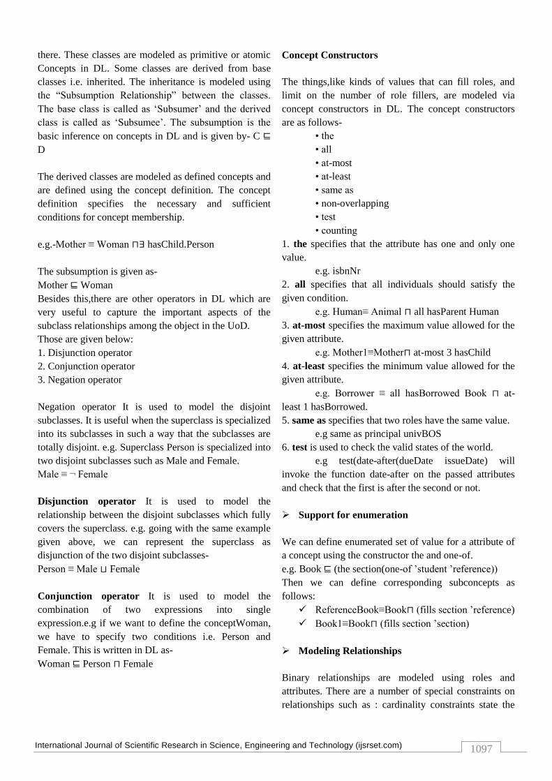
D. Example
Following is the transformation of the ER model in
fig.4.1 into equivalent knowledge base :
Figure 3. Transformation of ER model to DL model
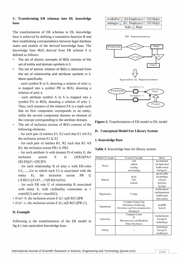
D. Conceptual Model For Library System
1. Knowledge Base
Table 1. Knowledge base for library system
International Journal of Scientific Research in Science, Engineering and Technology (ijsrset.com)
1100
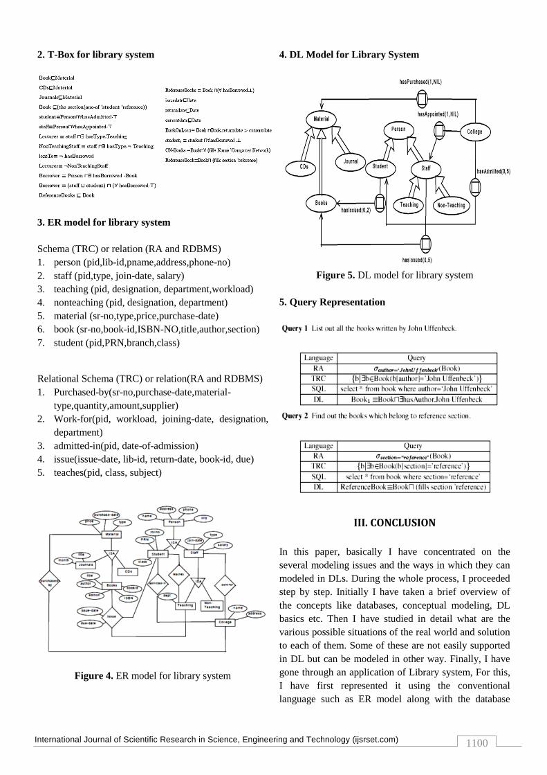
2. T-Box for library system
3. ER model for library system
Schema (TRC) or relation (RA and RDBMS)
1. person (pid,lib-id,pname,address,phone-no)
2. staff (pid,type, join-date, salary)
3. teaching (pid, designation, department,workload)
4. nonteaching (pid, designation, department)
5. material (sr-no,type,price,purchase-date)
6. book (sr-no,book-id,ISBN-NO,title,author,section)
7. student (pid,PRN,branch,class)
Relational Schema (TRC) or relation(RA and RDBMS)
1. Purchased-by(sr-no,purchase-date,material-
type,quantity,amount,supplier)
2. Work-for(pid, workload, joining-date, designation,
department)
3. admitted-in(pid, date-of-admission)
4. issue(issue-date, lib-id, return-date, book-id, due)
5. teaches(pid, class, subject)
Figure 4. ER model for library system
4. DL Model for Library System
Figure 5. DL model for library system
5. Query Representation
III. CONCLUSION
In this paper, basically I have concentrated on the
several modeling issues and the ways in which they can
modeled in DLs. During the whole process, I proceeded
step by step. Initially I have taken a brief overview of
the concepts like databases, conceptual modeling, DL
basics etc. Then I have studied in detail what are the
various possible situations of the real world and solution
to each of them. Some of these are not easily supported
in DL but can be modeled in other way. Finally, I have
gone through an application of Library system, For this,
I have first represented it using the conventional
language such as ER model along with the database
International Journal of Scientific Research in Science, Engineering and Technology (ijsrset.com)
1101
schema. Then I have modeled it with the DL
representation along with knowledge base. Then queries
are represented for each application using RA, TRC and
SQL. Then these representations are compared with the
query representation in DL. From the examples it is
clear that DL provides much clear and easy to learn
syntax as compared to conventional languages. As well
as DL also supports reasoning facilities which are
required to test correctness of the conceptual model.
IV. REFERENCES
[1] Franz Baader, Diego Calvanese , Deborah L.
McGuinness , Daniele Nardi, Peter F. Patel-
Schneider, “ The Description Logic Handbook:
Theory, Implementation and Applications”,
Cambridge University Press; 2 edition (June 28,
2010), ISBN-13: 978-0521150118.
[2] Vandana Mohan Patil, “Description Logic: A
Knowledge Representation Language”, IJCA
Proceedings on National Conference on Emerging
Trends in Information Technology NCETIT(2):1-5,
22 December 2014. (NCETIT/Number 2 (ISBN:
973-93-80884-61-3))
[3] Calvanese, Diego, and Giuseppe De Giacomo.
Expressive description logics. Cambridge University
Press, 2003.
[4] Borgida, Alexander, and Ronald J. Brachman.
"Conceptual Modeling with Description Logics." In
Description logic handbook, pp. 349-372. 2003.


![1234-1236-1238 AC_os11_2009feb17[1]](https://static.fdocuments.in/doc/165x107/55cf8d265503462b13926575/1234-1236-1238-acos112009feb171.jpg)