EQUIPMENT OPERATION MANUAL - equipment.loctite.com Setup.pdf · FOR YOUR SAFETY Safety Precautions...
34
EQUIPMENT OPERATION MANUAL LOCTITE ® SCARA-N ROBOT S440N Series Setup “For Qualified Installer ONLY”
Transcript of EQUIPMENT OPERATION MANUAL - equipment.loctite.com Setup.pdf · FOR YOUR SAFETY Safety Precautions...

EQUIPMENT OPERATION MANUAL
LOCTITE® SCARA-N ROBOT S440N Series
Setup “For Qualified Installer ONLY”

Thank you for purchasing this Loctite® SCARA-N Robot.
Read this manual thoroughly in order to properly use this robot. Be sure to read “For Your Safety” before you use the robot. It will protect you from possible dangers during operation.
After having read this manual, keep it in a handy place so that you or the operator can refer to it whenever necessary.

FOR YOUR SAFETY
Safety Precautions The precautions in this manual are provided for the customer to make the best use of this product safely, and to provide preventive measures against injury to the customer or damage to property.
・・・・・Be sure to follow the instructions・・・・・ Various symbols are used in this manual. Please read the following explanations of what each symbol stands for.
● Symbols Indicating the Degree of Damage or Danger The following symbols indicate the degree of damage or danger which may be incurred if you neglect the safety notes.
Warnings Cautions These “Cautions” indicate the possibility of accidental injury or damage
to property.
These “Warnings” indicate the possibility of death or serious injury.
● Symbols Indicating Type of Danger and Preventive Measures The following symbols indicate the type of safety measure that should be taken.
Indicates prohibition.
Do not touch. (Contact prohibition)
Never do this. (General prohibition)
Be sure to unplug power cord from wall outlet.
Do not disassemble, modify or repair.
Be sure to follow instructions.
Be sure to check grounding.
Indicates necessity.
Indicates the type of safety measure that should be taken.
Take care. (General caution)
Setup Loctite® SCARA-N S440N Robot i

FOR YOUR SAFETY
Warnings
Keep the emergency stop switch within reach of an operator while teaching or running the robot. Failure to do so may cause danger since the robot cannot be stopped immediately and safely.
Do not sprinkle water or oil on the robot, operation box, or power cord. Contact with water or oil can cause electric shock, fire, or malfunction of the unit. IP Protection Rating is “IP20.”
Power the unit only with the rated voltage. Excessive voltage can cause fire or malfunction of the unit.
Check the mounting screws regularly so that they are always firmly tightened. Loose screws may cause injury or breakdown.
Be sure to unplug the power cord from the wall outlet if the robot will remain unused for long periods of time. Gathered dust could lead to fire. Be sure to shut off the power supply before removing the power cord.
Regularly check that the I/O-S circuits and emergency stop switch work properly. Failure to do so may cause danger since the robot cannot be stopped immediately and safely.
Setup Loctite® SCARA-N S440N Robot ii

FOR YOUR SAFETY ■ INSTALLATION ■
Warnings
Always use a safety barrier. A person entering the robot’s maximum operating range may be injured. Install an interlock that triggers an emergency stop when the gate is opened at the entry gate of the safety barrier, using the I/O-S connector included in package. Ensure there is no other way of entering the restricted area. Furthermore, put up a “No Entry” or “No Operating” warning sign in a clearly visible position.
Example
Install a safety barrier of adequate strength so as to protect the operator from moving tools and flying objects. Always use protective wear (helmet, protective gloves, protective glasses, and protective footwear) when going inside the safety barrier.
Take adequate precautions against objects the robot is gripping, flying or falling off taking into account the object’s size, weight, temperature and chemical composition.
Setup Loctite® SCARA-N S440N Robot iii

FOR YOUR SAFETY
Confirm that the robot is properly grounded before use. Insufficient grounding can cause electric shock, fire, malfunction, or breakdown.
Do not attempt to disassemble or modify the robot. This may lead to electric shocks or fire.
Do not use the unit where flammable or corrosive gas is present. Leaked gas accumulated around the unit can cause fire or explosion.
Install the robot in a place which can endure its weight and conditions while running. Placing the unit in an insufficient or unstable surface may cause the unit to fall, overturn, or breakdown. This could result in operator injury.
Plug the power cord into the wall outlet firmly. Incomplete insertion into the wall outlet makes the plug hot and can cause fire. Check that the plug is not covered with dust. Be sure to shut off the power supply before connecting the power cord to the robot.
Be sure to use within the voltage range indicated on the unit. Failure to do so may cause electric shock or fire.
Place the unit in a well-ventilated area for the health and safety of the operator.
Turn off the unit before inserting and removing cables. Failure to do so may result in electric shock, fire, or malfunction of the unit.
Warnings
Do not block the air intake on the lower part of the back of the robot (18mm above the floor.) This may cause overheating or fire.
Setup Loctite® SCARA-N S440N Robot iv

FOR YOUR SAFETY
Warnings Be sure to confirm that all the air tubes are connected correctly and firmly.
Use the robot in an environment between 0 to 40 degrees centigrade with a humidity of 20 to 90 percent without condensation. Failure to do so may result in malfunction. IP Protection Rating is “IP20.”
Use the robot in an environment where no electric noise is present. Failure to do so may result in malfunction or breakdown.
Be sure to secure the movable parts of the robot before transportation. Failure to do so may result in injury or breakdown.
Do not bump or jar the unit while it is being transported or installed. This can cause breakdown.
Use the robot in an environment where it is not exposed to direct sunlight. Direct sunlight may cause malfunction or breakdown.
Be sure to confirm that tools such as the electric screwdriver unit, etc. are properly connected. Failure to do so may result in injury or breakdown.
Be sure to check the wiring to the main unit. Improper wiring may result in malfunction or breakdown.
Keep the emergency stop switch within reach of an operator. Failure to do so may cause danger since the robot cannot be stopped immediately and safely.
Be sure to shut off the power supply before plugging in the power cord.
Setup Loctite® SCARA-N S440N Robot v

FOR YOUR SAFETY
CautionsPlace the operation box on a flat surface more than 80 cm above the floor so that it is easier to operate it.
Use the unit in an environment that is not dusty or damp. Dust and dampness may lead to breakdown or malfunction. IP Protection Rating is “IP20.”
Setup Loctite® SCARA-N S440N Robot vi

FOR YOUR SAFETY ■ WORKING ENVIRONMENT ■
WarningsWhen you lubricate or inspect the unit, unplug the power cord from the robot. Failure to do so may result in electric shock or injury. Be sure to shut off the power supply before removing the power cord from the robot.
Always be aware of the robot's movement, even in the Teaching mode. Careful attention will protect the operator from injury.
Be sure to confirm that all the air tubes are connected correctly and firmly.
Install a safety barrier of adequate strength so as to protect the operator from moving tools and flying objects. Always use protective wear (helmet, protective gloves, protective glasses, and protective footwear) when going inside the safety barrier.
Keep the emergency stop switch within reach of an operator while teaching and running the robot. Failure to do so may cause danger since the robot cannot be stopped immediately and safely.
When going inside the safety barrier, place a “Do Not Operate” sign on the start switch.
Setup Loctite® SCARA-N S440N Robot vii

FOR YOUR SAFETY ■ DURING OPERATION ■
Warnings
When operations are taking place within the safety barrier, ensure no one enters the robot’s maximum operating range.
If you must go inside the safety barrier, be certain to push the emergency stop switch and put a “Do Not Operate” sign on the start switch.
When starting the robot, check that, no one is within the safety barrier and no object will interfere with the robot operating.
Under no circumstances should you go inside the safety barrier or place your hands or head inside the safety barrier while the robot is operating.
Keep the emergency stop switch within reach of an operator while teaching and running the robot. Failure to do so may cause danger since the robot cannot be stopped immediately and safely.
If anything unusual (e.g. a burning smell or abnormal sound) occurs, stop operation and unplug the cable immediately. Contact the dealer from which you purchased the robot or the office listed on the last page of this manual. Continuous use without repair can cause electric shock, fire, or breakdown of the unit.
Setup Loctite® SCARA-N S440N Robot viii

PREFACE
The Loctite® SCARA-N Robot S440N Series is a new low cost, high performance robot. The combined use of pulse motors and special micro step driving circuits saves you energy and space. There are several manuals pertaining to this robot.
Setup This manual explains how to set up the robot. Be sure to read this manual.
Maintenance This manual explains how to maintain the robot. Be sure to read this manual.
Basic Instructions This manual provides safety precautions, part names, and the basic knowledge necessary to operate the robot.
Quick Start This manual explains the actual operation of the robot with simple running samples.
Teaching Pendant Operation This manual explains how to operate the robot via the teaching pendant.
PC Operation This manual explains how to operate the robot from a computer (LR C-Points.) Features I This manual explains point teaching. Features II This manual explains commands, variables, and functions.
Features III This manual explains features such as run mode parameters, sequencer program, etc.
External Control I (I/O-SYS) This manual explains the I/O-SYS control.
External Control II (COM Communication)
This manual explains the COM communication control system (COM1 – COM3.)
Specifications This manual provides comprehensive specifications, including mechanical or electrical requirements.
Note: The product specifications in these manuals may differ from those of the robot you have received due to product improvement.
Please be sure to follow the instructions described in these manuals. Proper use of the robot will ensure continued functionality and high performance. The contents described in this manual are based on the standard application. Menu items may vary depending on models. “For Your Safety” is also provided so that the operator can make the best use of this robot safely. This book includes preventive measures that can be taken against injury to the operator or damage to property. Please be sure to read “For Your Safety” before using the robot.
Setup Loctite® SCARA-N S440N Robot ix

Be sure to shut off the power supply before plugging in the power cord.
BE SURE TO MAKE A PROPER GROUNDING WHEN YOU INSTALL THE ROBOT.
Be sure to save data whenever it is added or modified. Otherwise, changes will not be saved if the power to the robot is cut off.
Setup Loctite® SCARA-N S440N Robot x

CONTENTS
Setup FOR YOUR SAFETY _________________________________________________________________ i PREFACE_________________________________________________________________________ ix CONTENTS _______________________________________________________________________ xi
INSTALLATION _____________________________________________________________________1 Lifting ____________________________________________________________________________1 Arm Fixing Metals __________________________________________________________________2 Fixing____________________________________________________________________________3
S4404 _________________________________________________________________________3 S4403 _________________________________________________________________________4 Robot Fixing Parts (4 Places)________________________________________________________5
Arm _____________________________________________________________________________6
S4404 _________________________________________________________________________6 S4403 _________________________________________________________________________7
Wiring and Piping___________________________________________________________________7 Teaching Pendant Hanging Ring_______________________________________________________8 Safety Barrier Installation _____________________________________________________________9 Cable Connection _________________________________________________________________12 Ground Connection ________________________________________________________________14 Switching I/O-SYS and I/O-1 Power Supplies ____________________________________________15
HOW TO BACK UP UNIQUE NUMBER AND INITIAL SETTING DATA _________________________16
HOW TO INSTALL ROBOT SYSTEM SOFTWARE ________________________________________17
C & T DATA BACKUP _______________________________________________________________18
Setup Loctite® SCARA-N S440N Robot xi

INSTALLATION
Eyebolt (M8)
Lifting
Be sure to attach the eyebolt (M8) on top of the robot when lifting the robot with a crane, etc.
Install the robot in an environment:
・ Where it is not exposed to direct sunlight. ・ Where no electric noise is present. ・ That is well-ventilated and where no flammable or corrosive gas is present. ・ That is not dusty or damp. ・ That can support the robot’s weight. ・ That is between 0 to 40 degrees centigrade with a humidity of 20 to 90
percent.
Manual Lifting
When lifting the robot manually, fix the robot arm using the arm fixing metal and hold the parts indicated by arrows. See “Arm Fixing Metals” on the next page.
Setup Loctite® SCARA-N S440N Robot 1

Arm Fixing Metals To remove the arm fixing metal which fixes the Z base and J2 Arm to the base, remove the screws indicated by arrows.
Arm Fixing Metal Arm Fixing Metal
S4404 S4403
Setup Loctite® SCARA-N S440N Robot 2
Fixing Fix the robot to the mounting base using four M8 bolts.
■ S4404
Do not block the opening for the cooling fan on the back of the robot.
(Mounting hole)
When installing the robot, leave a space of 30 cm or more behind the robot so that it is easier to conduct maintenance.
Setup Loctite® SCARA-N S440N Robot 3

■ S4403
(Mounting hole)
Standard toolposition
Do not block the opening for the cooling fan on the back of the robot.
When installing the robot, leave a space of 30 cm or more behind the robot so that it is easier to conduct maintenance.
Setup Loctite® SCARA-N S440N Robot 4
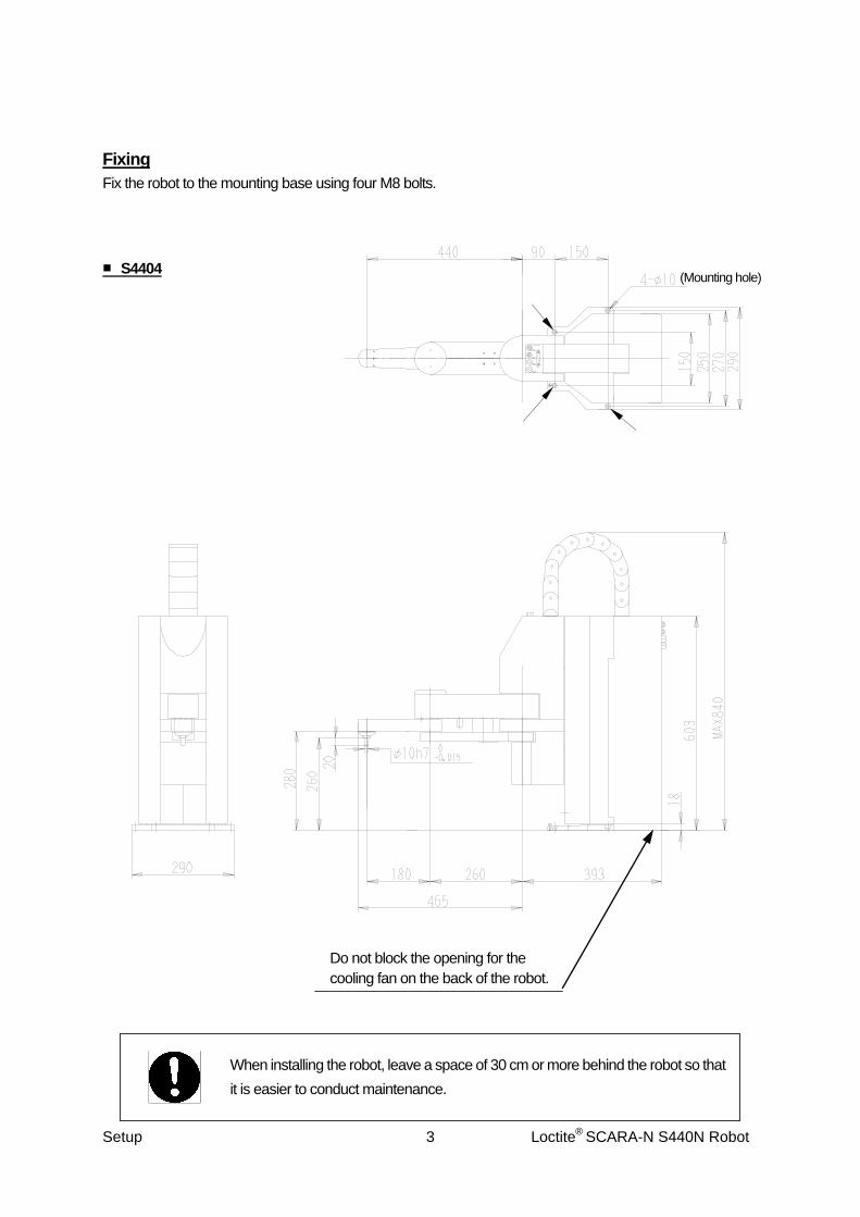
Robot Fixing Parts (4 Places)
The dimensions of the spot-faced mounting holes are the same for the S4404 and S4403.
Setup Loctite® SCARA-N S440N Robot 5
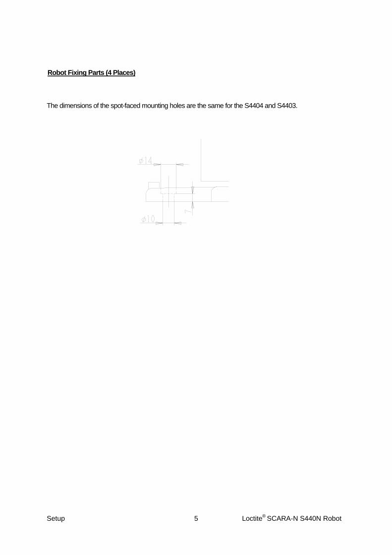
Arm
■ S4404
J4 (R) Axis center
Setup Loctite® SCARA-N S440N Robot 6

■ S4403
Wiring and Piping Quick coupler
(for an air pipe connector of φ 4 outside diameter)
D-Sub connector (Socket type with 15 Pin holes) Matched connector: D-Sub connector (Pin type with 15 Pins)
A
B
A and B are connected inside the robot.
Setup Loctite® SCARA-N S440N Robot 7

Teaching Pendant Hanging Ring
+ Pan Taptite screw 3x8 (B)
Hanging ring
Back of the Teaching Pendant
Setup Loctite® SCARA-N S440N Robot 8

Safety Barrier Installation A person entering the robot’s moving area risks being injured. Be sure to install a safety barrier that conforms to the following standards.
Install a safety barrier so that it cannot easily be moved. Install a safety barrier that will not fall over or easily get damaged. Install a safety barrier that impedes the passing through of heads or hands. Install an interlock that triggers an emergency stop when the gate is opened at the entry gate of
the safety barrier, using the I/O-S connector included in the package. Ensure there is no other way of entering the moving area.
Put up a “No Entry” or “No Opening” warning sign in a clearly visible position.
Example
For I/O-S connection, refer to the operation manual “Specifications.”
Install the safety barrier with reference to the following height and distance restrictions.
Setup Loctite® SCARA-N S440N Robot 9

Distance between the Robot’s Maximum Operating Range and the Safety Barrier (Indicated by the letter “c” in the figure below)
Barrier Height (b)
Maximum Operating Height (a)
1000 1200 1400 1600 1800 2000 2200 2400 2500
2,600 900 800 700 600 600 500 400 300 100 2,400 1,100 1,000 900 800 700 600 400 300 100 2,200 1,300 1,200 1,000 900 800 600 400 300 - 2,000 1,400 1,300 1,100 900 800 600 400 - - 1,800 1,500 1,400 1,100 900 800 600 - - - 1,600 1,500 1,400 1,100 900 800 500 - - - 1,400 1,500 1,400 1,100 900 800 - - - - 1,200 1,500 1,400 1,100 900 700 - - - - 1,000 1,500 1,400 1,000 800 - - - - - 800 1,500 1,300 900 600 - - - - -
(Unit: mm) Note 1: Do not use a safety barrier with a height of less than 1,000 mm because it is insufficient to restrict the
robot’s movements. Note 2: When a safety barrier with a height of less than 1,400 mm is used, other safety measures must be
taken. (These notes come from EN294: The safe distance between the operator and robot’s moving parts) The “maximum operating range” is the area that a tool attached to the robot or a workpiece held by the robot can reach.
Safety Barrier
Base Level
When the area sensor is installed at the entrance gate, be sure to maintain a safe distance.
Setup Loctite® SCARA-N S440N Robot 10
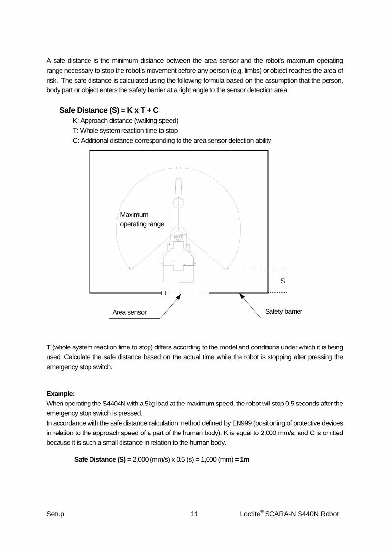
A safe distance is the minimum distance between the area sensor and the robot’s maximum operating range necessary to stop the robot’s movement before any person (e.g. limbs) or object reaches the area of risk. The safe distance is calculated using the following formula based on the assumption that the person, body part or object enters the safety barrier at a right angle to the sensor detection area.
Safe Distance (S) = K x T + C K: Approach distance (walking speed) T: Whole system reaction time to stop C: Additional distance corresponding to the area sensor detection ability
Maximum operating range
Safety barrier Area sensor
S
T (whole system reaction time to stop) differs according to the model and conditions under which it is being used. Calculate the safe distance based on the actual time while the robot is stopping after pressing the emergency stop switch. Example: When operating the S4404N with a 5kg load at the maximum speed, the robot will stop 0.5 seconds after the emergency stop switch is pressed. In accordance with the safe distance calculation method defined by EN999 (positioning of protective devices in relation to the approach speed of a part of the human body), K is equal to 2,000 mm/s, and C is omitted because it is such a small distance in relation to the human body.
Safe Distance (S) = 2,000 (mm/s) x 0.5 (s) = 1,000 (mm) = 1m
Setup Loctite® SCARA-N S440N Robot 11

Cable Connection
COM1
COM2
COM3
Operation Box Connector*
I/O-S*
TPU*
I/O-1
I/O-SYS
PC RS-232C for expansion
Be sure to connect a device (e.g. area sensor) to I/O-S. The robot will not start if nothing is connected. If you do not need to connect anything to TPU (teaching pendant connector) or operation box connector, connect the short connector to them. Use a dust cover on unused connectors to prevent any trouble with static or dust.
RS-232C for expansion
e.g. Area Sensor
Outlet (differs depending on its spec.)
Power Cord
Tool Piping
Tool Piping
Teaching Pendant
Setup Loctite® SCARA-N S440N Robot 12

Connector Mark Connecting Cord Connecting Device
I/O-SYS I/O-SYS Cable D-Sub 37 Pin Male Cable 989434 Interface Cable 98395
Loctite® Interface Junction Box 98549 Various Loctite® Dispensing Systems
COM 1 RS232C (Straight) 98648
PC, PLC, etc.
COM 2 RS232C (Straight) 98648
PC, PLC, etc.
COM 3 RS232C (Straight) 98648
PC, PLC, etc.
Operation box junction cable OPERATION
BOX
Included With Operation Box 987512
Molded with teaching pendant. Teaching Pendant 1015106 TPU
Short connector 989660
SAFETY GUARD Modify the connector included in the package to use as a connector cord.
Area sensor, safety guard switch, etc. SCARA Light Curtain 989852
100V Area such as North America, etc. Power Cord 8901466
Power supply: Single phase 90-132V, 50/60Hz
INLET CE (200v) 8901467Power Cord
Power supply: Single phase 180 – 250V, 50/60Hz
OUTLET
Power supply source specifications are same as those for INLET. MAX 3A
Setup Loctite® SCARA-N S440N Robot 13

Ground Connection The power cord is also used for grounding. Plug the power cord included in the package firmly into an appropriate ground outlet. If the ground outlet is not available, ground the robot using the grounding screw on the back of the robot and the grounding wire.
Back of the Robot
Outlet that Matches the Power Cord Included in the Package
Grounding screw
Confirm that the robot is properly grounded. Insufficient grounding can cause electric shock, fire, malfunction, or damage to the unit.
Warning
Setup Loctite® SCARA-N S440N Robot 14

Switching I/O-SYS and I/O-1 Power Supplies
Turn off the robot and remove the rear cover of the body to switch between “I/O-SYS Internal/External Power Selection Switch” and “I/O-1 Internal/External Power Selection Switch.”
DisplaySwitch IN EXT
I/O-SYS Power Selection Switch
Internal Power Supply
External Power Supply
I/O-1 Power Selection Switch
Internal Power Supply
External Power Supply
Slide Switch
Special Mode Switch I/O-SYS Internal/External Power Selection Switch
I/O-1 Internal/External Power Selection Switch
Spare Switch
Setup Loctite® SCARA-N S440N Robot 15

HOW TO BACK UP UNIQUE NUMBER AND INITIAL SETTING DATA
Each robot has a unique number and its own initial setting data. Be sure to back up this data since it may be necessary when replacing internal boards due to malfunction.
Be sure to back up the unique number and initial setting data of the robot. It may be necessary when replacing internal boards.
Preparation Check that the robot is properly connected to your PC, turn on the robot and the PC and copy “PSDBKUPE.EXE” from the operation manual CD-ROM to the local disk. 1. Start up “PSDBKUPE.EXE” from the local disk. The dialog
box will appear as shown to the right. 2. Select the COM port used to connect the PC to the robot
and click [OK.] 3. Click [Download] to start downloading the unique number
and initial setting data of the robot. If you want to select another COM port, select [COM Status] from the pull-down menu [COM.]
4. After downloading is complete, save it as a new file. (It is saved with the extension “.JPB”.) Click [Close]
to exit “PSDBKUPE.EXE.”
Do not select [Send C&T Data] from the pull-down menu [COM Status.] Use the [Send C & T Data] function only after replacing internal boards.
Setup Loctite® SCARA-N S440N Robot 16

HOW TO INSTALL ROBOT SYSTEM SOFTWARE
This robot is controlled by built-in “robot system software.” To upgrade the robot system software, follow the instructions below. (For this operation, the robot must be connected to a PC.) “Robot system software” is included in the operation manual CD-ROM with the file name, JSYLOADE.exe.
1. Turn off the robot, and then turn on the special mode switch. 2. Turn on the robot again, copy the “JSYLOADE” software included in operation manual CD-ROM to the
local disk on the PC and start it up. 3. Select the communication port status of your PC which is connected to the robot and then click [OK.] 4. Select [Open] on the dialog box and specify the robot system software to be downloaded. Then click
[Send.]
5. After data sending is complete, turn off the robot, turn OFF the special mode switch, and then attach
the cover again.
If you are using “LR C-Points”, the robot system software can also be upgraded by selecting [Send
Robot System Software] from the [Robot] pull-down menu.
Setup Loctite® SCARA-N S440N Robot 17

C & T DATA BACKUP
Back up data in case of accident. To create backup data, start up the program “LR C-Points Limited Edition” included on the operation manual CD-ROM. Retrieve data from the robot and save the retrieved data in a file.
The teaching data in combination with the customizing data is sent and received between the robot and PC as a unit of data. This unit of data is called “C & T data.” You cannot send or receive one particular program only.
Robot PC
Receive/Send data
Work area Storage area
Backup data
Setup Loctite® SCARA-N S440N Robot 18

The robot has a data storage area and a work area. When you start up the robot, the C & T data in the storage area will be copied to the work area. The copied data is used for running and teaching. The data in the work area will be deleted when the power to the robot is turned off. When retrieving data from the robot, it comes from the work area. After sending data from the PC to the robot, the sent data will be saved in the storage area automatically.
If you are using “LR C-Points”, it is also possible to back up the data by selecting [Receive C & T Data] from the [Robot] pull-down menu.
Setup Loctite® SCARA-N S440N Robot 19

Warranty Henkel Corporation warrants, to the original Buyer for a period of one (1) year from date of delivery, that the Loctite® Equipment or System sold by it is free from defects in material and workmanship. Henkel will, at its option, replace or repair said defective parts. This warranty is subject to the following exceptions and limitations. 1. Purchaser Responsibilities – The Purchaser shall be responsible for:
-Maintenance of the equipment as outlined in the Equipment Manual for the product. - Inventory of recommended maintenance parts established by Henkel; -Notification to Henkel within 6-8 hours of downtime. -Any cost of travel or transportation connected with warranty repair. -All cost associated with investigating or correcting any failure caused by the purchaser’s misuse, neglect or unauthorized alteration or repair. -All costs attributed to accident or other factors beyond Henkel’s control.
2. A thirty (30) day warranty will be extended on any items subject to normal wear, such as: -Pump Seals -Tubing -Wear Surfaces of Wiping Rollers -O-Rings -Hoses
Purchased items used in Loctite® dispensing equipment are covered under warranties of their respective manufacturers and are excluded from coverage under this warranty. Typical purchased items are: -Solenoids -Electrical Relays -Refrigeration Units -Timers -Fluid Power Cylinders -Electrical Motors 3. No warranty is extended to perishable items, such as:
-Fuses -Dispensing Needles -Dispensing Nozzles -Light Bulbs -Lamps -Product Barrels
Henkel reserves the right to make changes in design and/or improvements to its equipment without obligation to include these changes in any equipment previously manufactured.

Henkel’s warranty herein is in lieu of and excludes all other warranties of Henkel and its affiliated and related companies (hereinafter the “seller companies”), express, implied, statutory, or otherwise created under applicable law including, but not limited to, any warranty or merchantability and/or fitness for a particular purpose of use. In no event shall the seller and/or the seller companies be liable for any direct, indirect, special, incidental or consequential damages, including, but not limited to, loss of profits. In addition, this warranty shall not apply to any products, which have been subjected to abuse, misuse, improper installation, improper maintenance or operation, electrical failure or abnormal conditions; and to products, which have been tampered with, altered, modified, repaired or reworked by anyone not approved by seller. Buyer’s sole and exclusive remedy under this warranty shall be limited to, at seller’s discretion, the replacement or repair of any defective product or part thereof, or a refund of the purchase price paid by for the product in exchange for buyer’s return of the product to seller, free and clear of any and all liens and encumbrances of any nature.
HENKEL CORPORATION 1001 Trout Brook Crossing
Rocky Hill, CT 06067 1-800 LOCTITE
Tel: 800-562.8483 Fax: (860) 571-5465
The specifications of the robot or the contents of this manual may be modified without prior notice to improve its quality. No part of this manual may be reproduced in any form, including photocopying, reprinting, or translation to another language, without the prior written consent of HENKEL.
©2007, Henkel Company, All rights reserved.
Manual # 8901156 Setup, Dated 09/2007