Equipment - Hufco.com · 4300 Catalog Equipment HB632 Hydraulic Bender R12 ... 1” Hand Tube...
58
R Equipment
Transcript of Equipment - Hufco.com · 4300 Catalog Equipment HB632 Hydraulic Bender R12 ... 1” Hand Tube...

UREquipment
Parker Hannifin CorporationTube Fittings DivisionColumbus, Ohiohttp://www.parker.com/tfd
R2
4300 Catalog Equipment
HB632Hydraulic Bender
R12 – R16
Mandrel Bending Components
R16 – R18
CP432 Tube and Pipe Bender Kit
R19
Rolo-Flair Rotary, Manual(Sizes 2 to 12)
R26
Ferulset Ferrule Pre-Setter(Sizes 2 to 32)
R36
Porting Tools
Straight Thread Port Tap (Sizes 2 to 32)
R32
SAE Straight Thread Port Counterbore(Sizes 2 to 32)
R32
BSPP/BSPT Taps
R33
BSPP Counterbores
R33
Hydra-ToolHydraulic Flaring & Pre-Setting Tool
R27 – R29
Karryflare
R30
Vise Block and Flaring Pin(Sizes 4 to 24 and 6-38mm)
R25-R26
Flaring Tools
Flanging Pin and Die Sets
R23
Flanging Tools
Parflange 1025
R23
KloskutLarge (Sizes 12 to 32)
R21
In-ExDeburring Tool (Sizes 2-26)
R22
Cut-Off Saw 974250
R21
Tru-KutSawing Vise (Sizes 3-32)
R21
KloskutMedium (Sizes 2 to 18)
R21
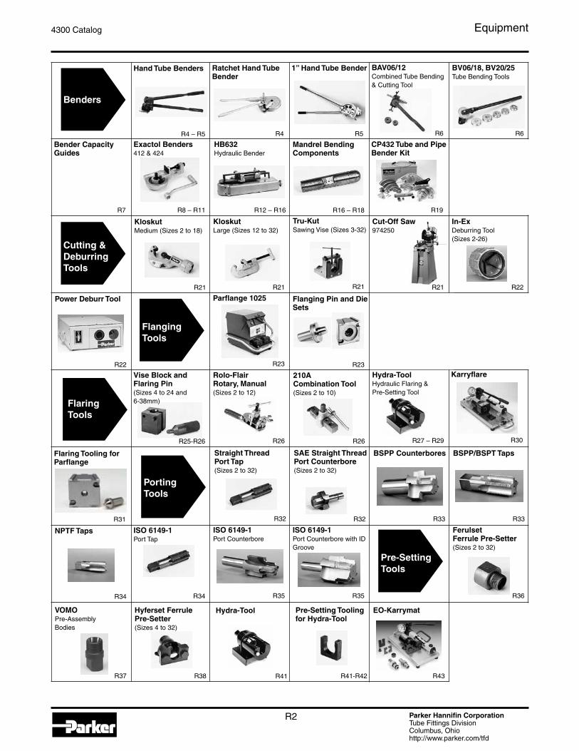
1” Hand Tube Bender
R5
BV06/18, BV20/25Tube Bending Tools
R6
Benders
Hand Tube Benders
R4 – R5
Ratchet Hand Tube Bender
R4
BAV06/12Combined Tube Bending & Cutting Tool
R6
Exactol Benders412 & 424
R8 – R11
Cutting & Deburring Tools
Power Deburr Tool
R22
210A Combination Tool(Sizes 2 to 10)
R26
Flaring Tooling for Parflange
R31
ISO 6149-1Port Counterbore
R35
ISO 6149-1Port Counterbore with ID Groove
R35
Pre-Setting Tools
VOMOPre-Assembly Bodies
R37
Bender Capacity Guides
R7
ISO 6149-1Port Tap
R34
NPTF Taps
R34
Pre-Setting Tooling for Hydra-Tool
R41-R42
Hyferset Ferrule Pre-Setter(Sizes 4 to 32)
R38
EO-Karrymat
R43
Hydra-Tool
R41
Parker Hannifin CorporationTube Fittings DivisionColumbus, Ohiohttp://www.parker.com/tfd
R3
4300 Catalog Equipment
PTFE Tape
R50
Loctite 7649 Primer N
R50
Pipe Sealing Cord
R50
Loctite Penetrating Oil
R48
O-Lube
R48
Super O-Lube
R48
O-Ring Pick
R45
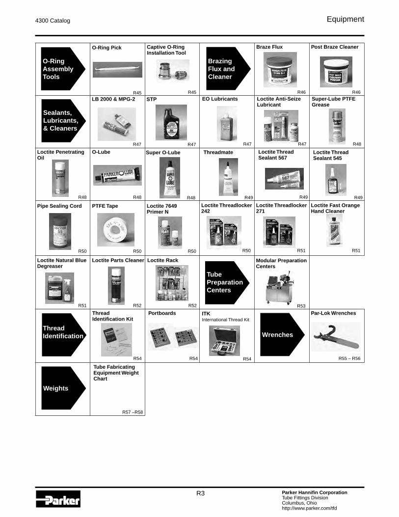
O-Ring Assembly Tools
Captive O-Ring Installation Tool
R45
Par-Lok Wrenches
R55 – R56
Sealants, Lubricants, & Cleaners
LB 2000 & MPG-2
R47
Loctite Anti-Seize Lubricant
R47
Loctite Thread Sealant 567
R49
Loctite Thread Sealant 545
R49
Loctite Threadlocker 242
R50
Loctite Threadlocker 271
R51
EO Lubricants
R47
STP
R47
Threadmate
R49
Modular Preparation Centers
R53
Tube Preparation Centers
Thread Identification
Thread Identification Kit
R54
Portboards
R54
ITKInternational Thread Kit
R54
Wrenches
Super-Lube PTFE Grease
R48
Loctite Fast Orange Hand Cleaner
R51
Loctite Natural Blue Degreaser
R51
Loctite Rack
R52
Loctite Parts Cleaner
R52
Weights
Tube Fabricating Equipment Weight Chart
R57 –R58
Braze Flux
R46
Post Braze Cleaner
R46
Brazing Flux andCleaner
Parker Hannifin CorporationTube Fittings DivisionColumbus, Ohiohttp://www.parker.com/tfd
R4
4300 Catalog Equipment
Dimensions and pressures for reference only, subject to change.
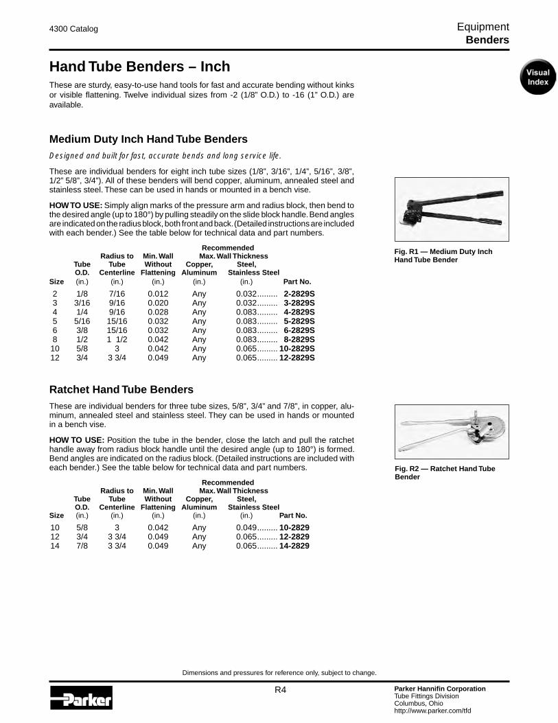
Hand Tube Benders – InchThese are sturdy, easy-to-use hand tools for fast and accurate bending without kinks or visible flattening. Twelve individual sizes from -2 (1/8” O.D.) to -16 (1” O.D.) are available.
Medium Duty Inch Hand Tube BendersDesigned and built for fast, accurate bends and long service life.
These are individual benders for eight inch tube sizes (1/8”, 3/16”, 1/4”, 5/16”, 3/8”, 1/2” 5/8”, 3/4”). All of these benders will bend copper, aluminum, annealed steel and stainless steel. These can be used in hands or mounted in a bench vise.
HOW TO USE: Simply align marks of the pressure arm and radius block, then bend to the desired angle (up to 180°) by pulling steadily on the slide block handle. Bend angles are indicated on the radius block, both front and back. (Detailed instructions are included with each bender.) See the table below for technical data and part numbers.
Recommended Radius to Min. Wall Max. Wall Thickness Tube Tube Without Copper, Steel, O.D. Centerline Flattening Aluminum Stainless Steel Size (in.) (in.) (in.) (in.) (in.) Part No.
2 1/8 7/16 0.012 Any 0.032 ......... 2-2829S 3 3/16 9/16 0.020 Any 0.032 ......... 3-2829S 4 1/4 9/16 0.028 Any 0.083 ......... 4-2829S 5 5/16 15/16 0.032 Any 0.083 ......... 5-2829S 6 3/8 15/16 0.032 Any 0.083 ......... 6-2829S 8 1/2 1 1/2 0.042 Any 0.083 ......... 8-2829S 10 5/8 3 0.042 Any 0.065 ......... 10-2829S 12 3/4 3 3/4 0.049 Any 0.065 ......... 12-2829S
Ratchet Hand Tube BendersThese are individual benders for three tube sizes, 5/8”, 3/4” and 7/8”, in copper, alu-minum, annealed steel and stainless steel. They can be used in hands or mounted in a bench vise.
HOW TO USE: Position the tube in the bender, close the latch and pull the ratchet handle away from radius block handle until the desired angle (up to 180°) is formed. Bend angles are indicated on the radius block. (Detailed instructions are included with each bender.) See the table below for technical data and part numbers.
Recommended Radius to Min. Wall Max. Wall Thickness Tube Tube Without Copper, Steel, O.D. Centerline Flattening Aluminum Stainless Steel Size (in.) (in.) (in.) (in.) (in.) Part No.
10 5/8 3 0.042 Any 0.049 ......... 10-2829 12 3/4 3 3/4 0.049 Any 0.065 ......... 12-2829 14 7/8 3 3/4 0.049 Any 0.065 ......... 14-2829
Fig. R1 — Medium Duty Inch Hand Tube Bender
Fig. R2 — Ratchet Hand Tube Bender
Benders
Parker Hannifin CorporationTube Fittings DivisionColumbus, Ohiohttp://www.parker.com/tfd
R5
4300 Catalog Equipment
Dimensions and pressures for reference only, subject to change.
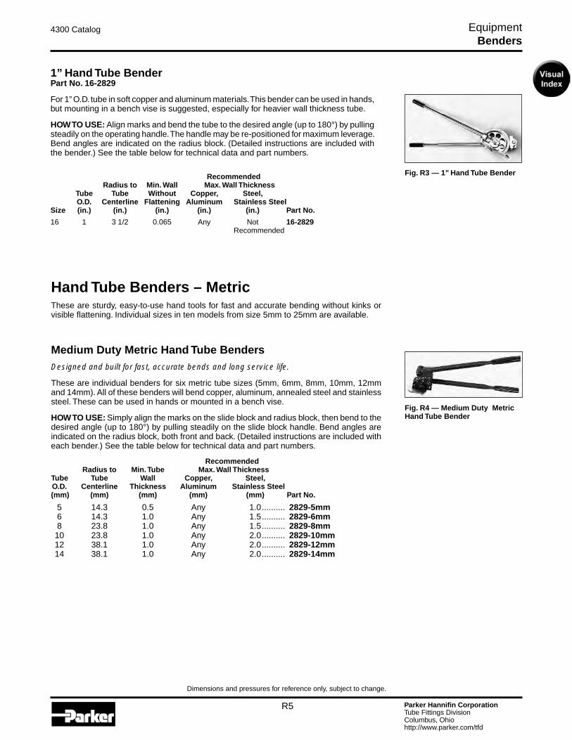
Fig. R3 — 1” Hand Tube Bender
1” Hand Tube BenderPart No. 16-2829
For 1” O.D. tube in soft copper and aluminum materials. This bender can be used in hands, but mounting in a bench vise is suggested, especially for heavier wall thickness tube.
HOW TO USE: Align marks and bend the tube to the desired angle (up to 180°) by pulling steadily on the operating handle. The handle may be re-positioned for maximum leverage. Bend angles are indicated on the radius block. (Detailed instructions are included with the bender.) See the table below for technical data and part numbers.
Recommended Radius to Min. Wall Max. Wall Thickness Tube Tube Without Copper, Steel, O.D. Centerline Flattening Aluminum Stainless Steel Size (in.) (in.) (in.) (in.) (in.) Part No.
16 1 3 1/2 0.065 Any Not ............16-2829 Recommended
Hand Tube Benders – MetricThese are sturdy, easy-to-use hand tools for fast and accurate bending without kinks or visible flattening. Individual sizes in ten models from size 5mm to 25mm are available.
Medium Duty Metric Hand Tube BendersDesigned and built for fast, accurate bends and long service life.
These are individual benders for six metric tube sizes (5mm, 6mm, 8mm, 10mm, 12mm and 14mm). All of these benders will bend copper, aluminum, annealed steel and stainless steel. These can be used in hands or mounted in a bench vise.
HOW TO USE: Simply align the marks on the slide block and radius block, then bend to the desired angle (up to 180°) by pulling steadily on the slide block handle. Bend angles are indicated on the radius block, both front and back. (Detailed instructions are included with each bender.) See the table below for technical data and part numbers.
Recommended Radius to Min. Tube Max. Wall Thickness Tube Tube Wall Copper, Steel, O.D. Centerline Thickness Aluminum Stainless Steel (mm) (mm) (mm) (mm) (mm) Part No.
5 14.3 0.5 Any 1.0 .......... 2829-5mm 6 14.3 1.0 Any 1.5 .......... 2829-6mm 8 23.8 1.0 Any 1.5 .......... 2829-8mm 10 23.8 1.0 Any 2.0 .......... 2829-10mm 12 38.1 1.0 Any 2.0 .......... 2829-12mm 14 38.1 1.0 Any 2.0 .......... 2829-14mm
Fig. R4 — Medium Duty Metric Hand Tube Bender
Benders

Parker Hannifin CorporationTube Fittings DivisionColumbus, Ohiohttp://www.parker.com/tfd
R6
4300 Catalog Equipment
Dimensions and pressures for reference only, subject to change.
Fig. R6 — BV06/18KPLX
Vise Mount Metric Hand BendersVise Mount Metric Bender – 6/18mmThis bender has six interchangeable rollers to cover tube sizes 6mm, 8mm, 10mm, 12mm, 14mm, 15mm, 16mm, and 18mm.
Part Description Part No.Vise Mount Tube Bender (6mm, 8mm, 10mm, 12mm, 14mm, 15mm, 16mm, 18mm) ....... BV06/18KPLX
Vise Mount Metric Bender – 20/25mmThis bender has three interchangeable rollers to cover tube sizes 20mm, 22mm, and 25mm. All bend radii are 86.5mm. Pressure arm is not included with the BV20/25KPLX, however it can be manufactured on site with a piece of tube, or it can be ordered separately with part number BV20/2510X. Maximum wall thickness for all sizes is 2.0mm.
Part Description Part No.Vise Mount Tube Bender (20mm, 22mm, 25mm) ....................... BV20/25KPLXPressure Arm ............................................................................. BV20/2510X
Fig. R7 — BV20/25KPLX
Benders
Tube O.D. (mm)
Bend Radius (mm)
Max. Wall Thickness
(mm)6 33 2.58 34 2.5
10 36 2.512 37 2.514 37 2.015 44 2.016 44 2.018 52 2.0
Bench Mount Metric Hand Bender and Cutting GuideThis bender combines a tube cutting guide with the bender for sizes 6mm, 8mm, 10mm, and 12mm. There are three bender rollers that cover all sizes. The bender mounts easily to a work bench or table.
Part Description Part No.Bench Mount Tube Bender (6mm, 8mm, 10mm, 12mm) ............ BAV06/12KPLX
Fig. R5 — BAV06/12KPLX
Parker Hannifin CorporationTube Fittings DivisionColumbus, Ohiohttp://www.parker.com/tfd
R7
4300 Catalog Equipment
Dimensions and pressures for reference only, subject to change.
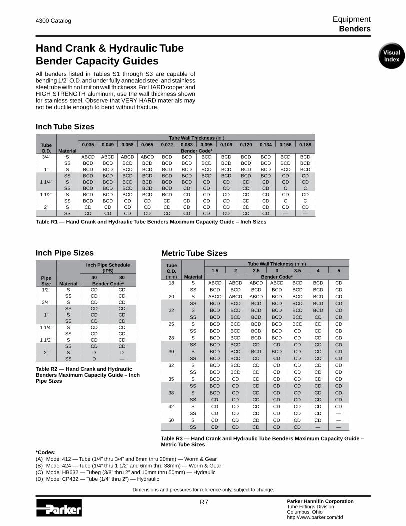
Hand Crank & Hydraulic Tube Bender Capacity GuidesAll benders listed in Tables S1 through S3 are capable of bending 1/2” O.D. and under fully annealed steel and stainless steel tube with no limit on wall thickness. For HARD copper and HIGH STRENGTH aluminum, use the wall thickness shown for stainless steel. Observe that VERY HARD materials may not be ductile enough to bend without fracture.
Inch Tube Sizes
Table R1 — Hand Crank and Hydraulic Tube Benders Maximum Capacity Guide – Inch Sizes
Table R3 — Hand Crank and Hydraulic Tube Benders Maximum Capacity Guide – Metric Tube Sizes
Table R2 — Hand Crank and Hydraulic Benders Maximum Capacity Guide – Inch Pipe Sizes
*Codes:(A) Model 412 — Tube (1/4” thru 3/4” and 6mm thru 20mm) — Worm & Gear(B) Model 424 — Tube (1/4” thru 1 1/2” and 6mm thru 38mm) — Worm & Gear(C) Model HB632 — Tubeg (3/8” thru 2” and 10mm thru 50mm) — Hydraulic(D) Model CP432 — Tube (1/4” thru 2”) — Hydraulic
Metric Tube SizesInch Pipe Sizes
Benders
PipeSize Material
Inch Pipe Schedule (IPS)
40 80Bender Code*
1/2" S CD CDSS CD CD
3/4" S CD CDSS CD CD
1" S CD CDSS CD CD
1 1/4" S CD CDSS CD CD
1 1/2" S CD CDSS CD CD
2" S D DSS D —
TubeO.D. Material
Tube Wall Thickness (in.)0.035 0.049 0.058 0.065 0.072 0.083 0.095 0.109 0.120 0.134 0.156 0.188
Bender Code*3/4" S ABCD ABCD ABCD ABCD BCD BCD BCD BCD BCD BCD BCD BCD
SS BCD BCD BCD BCD BCD BCD BCD BCD BCD BCD BCD BCD1" S BCD BCD BCD BCD BCD BCD BCD BCD BCD BCD BCD BCD
SS BCD BCD BCD BCD BCD BCD BCD BCD BCD BCD CD CD1 1/4" S BCD BCD BCD BCD BCD BCD CD CD CD CD CD CD
SS BCD BCD BCD BCD BCD CD CD CD CD CD C C1 1/2" S BCD BCD BCD BCD BCD CD CD CD CD CD CD CD
SS BCD BCD CD CD CD CD CD CD CD CD C C2" S CD CD CD CD CD CD CD CD CD CD CD CD
SS CD CD CD CD CD CD CD CD CD CD — —
TubeO.D.(mm) Material
Tube Wall Thickness (mm)1.5 2 2.5 3 3.5 4 5
Bender Code*18 S ABCD ABCD ABCD ABCD BCD BCD CD
SS BCD BCD BCD BCD BCD BCD CD20 S ABCD ABCD ABCD BCD BCD BCD CD
SS BCD BCD BCD BCD BCD BCD CD22 S BCD BCD BCD BCD BCD BCD CD
SS BCD BCD BCD BCD BCD CD CD25 S BCD BCD BCD BCD BCD CD CD
SS BCD BCD BCD BCD CD CD CD28 S BCD BCD BCD BCD CD CD CD
SS BCD BCD CD CD CD CD CD30 S BCD BCD BCD BCD CD CD CD
SS BCD BCD CD CD CD CD CD32 S BCD BCD CD CD CD CD CD
SS BCD BCD CD CD CD CD CD35 S BCD CD CD CD CD CD CD
SS BCD CD CD CD CD CD CD38 S BCD CD CD CD CD CD CD
SS CD CD CD CD CD CD CD42 S CD CD CD CD CD CD CD
SS CD CD CD CD CD CD —50 S CD CD CD CD CD CD —
SS CD CD CD CD CD — —
Parker Hannifin CorporationTube Fittings DivisionColumbus, Ohiohttp://www.parker.com/tfd
R8
4300 Catalog Equipment
Dimensions and pressures for reference only, subject to change.
Exactol® Crank-Operated BendersModels 412/424
These portable benders are vise or bench mountable for easy action and fast accurate bending to 180°. Two models are available to bend tube sizes 4 (1/4”) through 24 (1 1/2”). Exactol benders are designed with a worm-gear drive with a 60 to 1 gear ratio to allow accurate bending with minimum effort. They bend aluminum, copper, annealed steel and an-nealed stainless steel without kinks or wrinkles. Easy crank operation permits continuous production without excessive operator fatigue; for use in tube fabrication shops, in the field, or in factory maintenance departments.
A video (on DVD) is included to provide proper instructions for use.
Exactol® Model 412The Exactol Model 412 will bend tube from size 4 (1/4”) through size 12 (3/4”) and 6mm through 20mm inclusive and is completely portable. Accessories include a sturdy metal car-rying case, which accommodates the 412 bender, slide block, and selected radius blocks. See page R7 for wall thickness capabilities. May be held in a vise or bench mounted using the bench mounting adapter. Bulletin 4391-B400S and DVD are included with bender, which describe the operation in detail.
NOTE: The 412 must be bench mounted if mandrels are used.
COMPONENTS REQUIREDThe minimum components required are a Model 412 Bender with a slide block and a radius block which match the tube O.D. to be bent.
Part Name Part No.Exactol Model 412 Bender (for 1/4” through 3/4” O.D.) ............... 560569Slide Block (for sizes 4-5-6-8-10-12) .......................................... 550585Slide Block (for sizes 6mm-8mm-12mm-12mm-14mm) ............. 820091Slide Block (for sizes 15mm-16mm-18mm-20mm) ..................... 820092Radius Blocks (for sizes 4-5-6-8-10-12 and 6mm thru 38mm) ... See pages R10 – R11
OPTIONAL ACCESSORIESCarrying Case (for bender, slide block and selected radius blocks) ............ 550572Bench Mounting Adapter ............................................................ 550570
Mandrel Bending Components for 412 and 424 Benders ............................................................ See pages R16 – R18
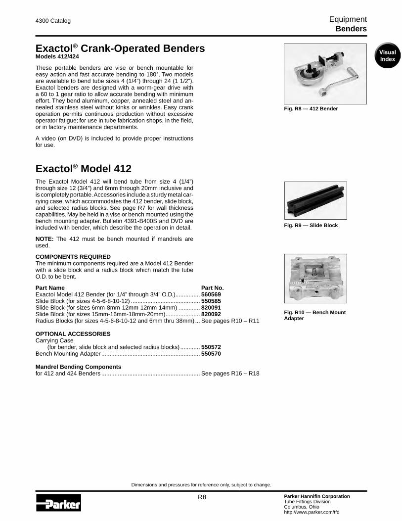
Fig. R8 — 412 Bender
Fig. R9 — Slide Block
Fig. R10 — Bench Mount Adapter
Benders

Parker Hannifin CorporationTube Fittings DivisionColumbus, Ohiohttp://www.parker.com/tfd
R9
4300 Catalog Equipment
Dimensions and pressures for reference only, subject to change.
Fig. R12 — 424 Bender
Fig. R13 — Slide Block
Exactol® Model 412 KitThis 412 kit contains all the basic tool requirements for bending tube from 1/4” through 3/4”. Part No. 412 KIT
The following part numbers are included in the kit:
Part Name Part No.Exactol Model 412 Bender ......................................................... 560569Carrying Case ............................................................................ 550572Slide Block for 1/4” through 3/4” tube ......................................... 550585Radius Block – 1/4” O.D. tube .................................................... 550579Radius Block – 3/8” O.D. tube ..................................................... 550581Radius Block – 1/2” O.D. tube ..................................................... 550582Radius Block – 5/8” O.D. tube ..................................................... 550583Radius Block – 3/4” O.D. tube ..................................................... 550584
Exactol® Model 424The Exactol Model 424 will bend tube from size 4 (1/4” O.D.) through size 24 (1 1/2” O.D.) and 6mm through 38mm inclusive. See page R7 for wall thickness capabilities. It is completely por-table and may be vise or bench mounted. Bulletin 4391-B400S and video are included with the bender, which describe the operation in detail.
NOTE: The 424 must be bench mounted if mandrels are used.
A video (on DVD) is included to provide proper instructions for use.
COMPONENTS REQUIREDThe minimum components required are a Model 424 Bender with a slide block and a radius block that match the tube O.D. to be bent.
Part Name Part No.Exactol Model 424 bender (for 1/4” through 1 1/2” O.D.) ............ 621044Slide Block (for sizes 4-5-6-8-10-12) .......................................... 550585Slide Block (for sizes 14-16-18-20) ............................................. 621045Slide Block (for size 24) .............................................................. 870150Slide Block (for sizes 6mm-8mm-10mm-12mm-14mm) ............. 820091Slide Block (for sizes 15mm-16mm-18mm-20mm) ..................... 820092Slide Block (for sizes 22mm-25mm-28mm-30mm) ..................... 820093Slide Block (for size 35mm) ........................................................ 820094Slide Block (for size 38mm) ........................................................ 870150Radius Blocks (for sizes -4 thru -24 and 6mm thru 38mm) ........ See pages R10 – R11
OPTIONAL ACCESSORIESBench Mounting Adapter ............................................................ 631156Mandrel Bending Components for 412 and 424 Benders ........................................................ See pages R16 – R18
Fig. R11 — 412 Kit
Benders
Parker Hannifin CorporationTube Fittings DivisionColumbus, Ohiohttp://www.parker.com/tfd
R10
4300 Catalog Equipment
Dimensions and pressures for reference only, subject to change.
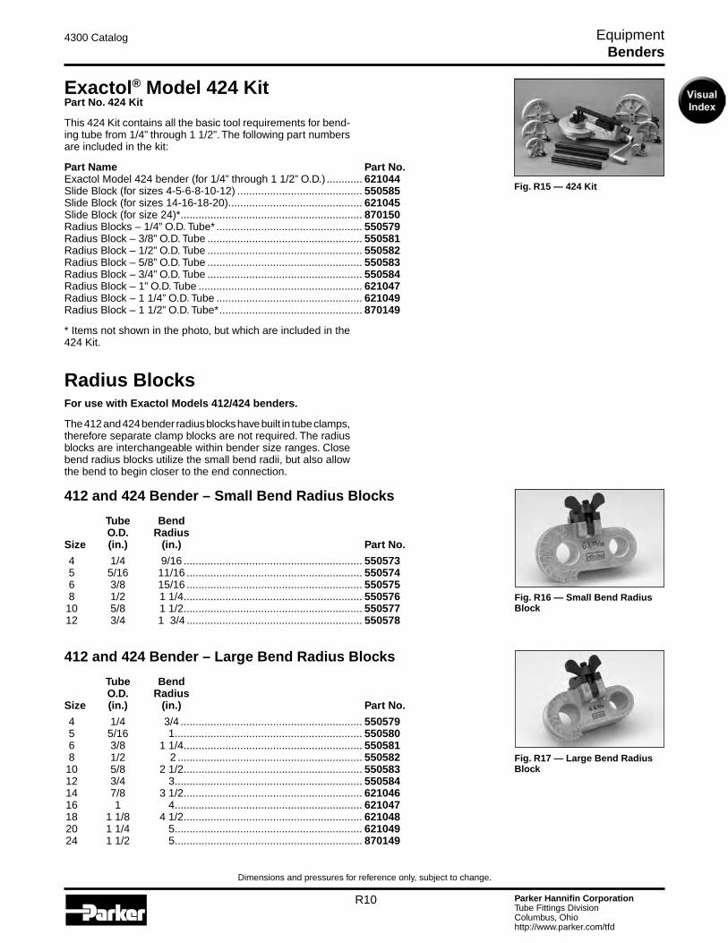
Fig. R15 — 424 Kit
Exactol® Model 424 KitPart No. 424 Kit
This 424 Kit contains all the basic tool requirements for bend-ing tube from 1/4” through 1 1/2”. The following part numbers are included in the kit:
Part Name Part No.Exactol Model 424 bender (for 1/4” through 1 1/2” O.D.) ............ 621044Slide Block (for sizes 4-5-6-8-10-12) .......................................... 550585Slide Block (for sizes 14-16-18-20) ............................................. 621045Slide Block (for size 24)* ............................................................. 870150Radius Blocks – 1/4” O.D. Tube* ................................................. 550579Radius Block – 3/8” O.D. Tube .................................................... 550581Radius Block – 1/2” O.D. Tube .................................................... 550582 Radius Block – 5/8” O.D. Tube .................................................... 550583Radius Block – 3/4” O.D. Tube .................................................... 550584 Radius Block – 1” O.D. Tube ....................................................... 621047Radius Block – 1 1/4” O.D. Tube ................................................. 621049Radius Block – 1 1/2” O.D. Tube* ................................................ 870149
* Items not shown in the photo, but which are included in the 424 Kit.
Radius BlocksFor use with Exactol Models 412/424 benders.
The 412 and 424 bender radius blocks have built in tube clamps, therefore separate clamp blocks are not required. The radius blocks are interchangeable within bender size ranges. Close bend radius blocks utilize the small bend radii, but also allow the bend to begin closer to the end connection.
412 and 424 Bender – Small Bend Radius Blocks Tube Bend O.D. Radius Size (in.) (in.) Part No.
4 1/4 9/16 ............................................................ 550573 5 5/16 11/16 ........................................................... 550574 6 3/8 15/16 ........................................................... 550575 8 1/2 1 1/4 ............................................................ 550576 10 5/8 1 1/2 ............................................................ 550577 12 3/4 1 3/4 ........................................................... 550578
412 and 424 Bender – Large Bend Radius Blocks Tube Bend O.D. Radius Size (in.) (in.) Part No.
4 1/4 3/4 ............................................................. 550579 5 5/16 1 ............................................................... 550580 6 3/8 1 1/4 ............................................................ 550581 8 1/2 2 .............................................................. 550582 10 5/8 2 1/2 ............................................................ 550583 12 3/4 3 ............................................................... 550584 14 7/8 3 1/2 ............................................................ 621046 16 1 4 ............................................................... 621047 18 1 1/8 4 1/2 ............................................................ 621048 20 1 1/4 5 ............................................................... 621049 24 1 1/2 5 ............................................................... 870149
Benders
Fig. R16 — Small Bend Radius Block
Fig. R17 — Large Bend Radius Block
Parker Hannifin CorporationTube Fittings DivisionColumbus, Ohiohttp://www.parker.com/tfd
R11
4300 Catalog Equipment
Dimensions and pressures for reference only, subject to change.
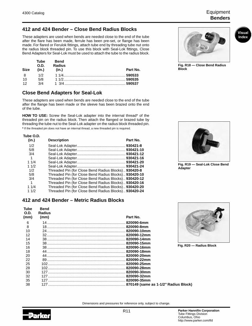
Fig. R18 — Close Bend Radius Block
Fig. R19 — Seal-Lok Close Bend Adapter
412 and 424 Bender – Close Bend Radius BlocksThese adapters are used when bends are needed close to the end of the tube after the flare has been made, ferrule has been pre-set, or flange has been made. For flared or Ferulok fittings, attach tube end by threading tube nut onto the radius block threaded pin. To use this block with Seal-Lok fittings, Close Bend Adapters for Seal-Lok must be used to attach the tube to the radius block. Tube Bend O.D. Radius Size (in.) (in.) Part No.
8 1/2 1 1/4 ............................................................ 590533 10 5/8 1 1/2 ............................................................ 590535 12 3/4 1 3/4 ........................................................... 590537
Close Bend Adapters for Seal-LokThese adapters are used when bends are needed close to the end of the tube after the flange has been made or the sleeve has been brazed onto the end of the tube.
HOW TO USE: Screw the Seal-Lok adapter into the internal thread* of the threaded pin on the radius block. Then attach the flanged or brazed tube by threading the tube nut to the Seal-Lok adapter on the radius block threaded pin.* If the threaded pin does not have an internal thread, a new threaded pin is required. Tube O.D. (in.) Description Part No.
1/2 Seal-Lok Adapter ............................................... 930421-8 5/8 Seal-Lok Adapter ............................................... 930421-10 3/4 Seal-Lok Adapter ............................................... 930421-12 1 Seal-Lok Adapter ............................................... 930421-16 1 1/4 Seal-Lok Adapter ............................................... 930421-20 1 1/2 Seal-Lok Adapter ............................................... 930421-24 1/2 Threaded Pin (for Close Bend Radius Blocks) .. 930420-8 5/8 Threaded Pin (for Close Bend Radius Blocks) .. 930420-10 3/4 Threaded Pin (for Close Bend Radius Blocks) .. 930420-12 1 Threaded Pin (for Close Bend Radius Blocks) .. 930420-16 1 1/4 Threaded Pin (for Close Bend Radius Blocks) .. 930420-20 1 1/2 Threaded Pin (for Close Bend Radius Blocks) .. 930420-24
412 and 424 Bender – Metric Radius Blocks Tube Bend O.D. Radius (mm) (mm) Part No.
6 14 ............................................................................ 820090-6mm 8 18 ............................................................................ 820090-8mm 10 24 ............................................................................ 820090-10mm 12 32 ............................................................................ 820090-12mm 14 38 ............................................................................ 820090-14mm 15 38 ............................................................................ 820090-15mm 16 38 ............................................................................ 820090-16mm 18 44 ............................................................................ 820090-18mm 20 44 ............................................................................ 820090-20mm 22 89 ............................................................................ 820090-22mm 25 102 ........................................................................... 820090-25mm 28 102 ........................................................................... 820090-28mm 30 127 ........................................................................... 820090-30mm 32 127 ........................................................................... 820090-32mm 35 127 ........................................................................... 820090-35mm 38 127 ........................................................................... 870149 (same as 1-1/2” Radius Block)
Fig. R20 — Radius Block
Benders

Parker Hannifin CorporationTube Fittings DivisionColumbus, Ohiohttp://www.parker.com/tfd
R12
4300 Catalog Equipment
Dimensions and pressures for reference only, subject to change.
Hydraulic Tube Bender Model HB632Hydraulic power does the work in bending tube of all materials in sizes from 6 (3/8” O.D.) through size 32 (2” O.D.), 10mm through 50mm, with wall thicknesses as great as .188 for an-nealed steel, and pipe sizes from 3/8” through 1-1/2”. See page R7 for wall thickness capabilities. The radius block, around which the tube is bent, is driven by a roller chain and sprocket powered by a cylinder and a separate hydraulic power unit.
Maximum bend angle is 180° with radii from 1 1/4” to 8”. Close second bends can be performed in either direction. An adjust-able stop controls the degree of bend to a maximum of 180° and is graduated in 1° increments. After the bend is completed and pressure is released, a spring returns the clamp arm to the zero starting position.
The clamp vise arm features a quick release speed screw for positioning the required clamp block. Each size of tube requires the proper sized radius block, clamp block and slide block.
Written instructions, a DVD and Bulletin 4391-B26 are included with each bender.
HB632 radius blocks, slide blocks and clamp blocks will work with the following benders as well: 624, 824, 832 and 848.
NOTE: For size 28 (1 3/4” O.D. tube) through 32 (2” O.D. tube) radius blocks, an adapter plate is required.
DIMENSIONS: L – 40” W – 11” H – 12”
COMPONENTS REQUIREDMinimum components required are a Model HB632 Bender, hose assembly, hydraulic pump and a radius, slide and clamp block which match the tube/pipe O.D. to be bent.
Part Name Part No.Hydraulic Bender Model HB632 (without pump) ........................ 631050Hydraulic Pump (10,000 psi, 110V AC) ...................................... 900085High Flow Hydraulic Pump (10,000 psi, 110V) ........................... 974691Hose Assembly (3’ long) ............................................................. 910004
One each of the following is required per tube O.D.: Radius Block, Clamp Block, Slide Block.Radius Block ............................................................................... See pages R13 – R15
INCH TUBE SIZESClamp Block (for -6) .................................................................... 864266Clamp Block (for -8, -12, -16, -24) .............................................. 631092Clamp Block (for -10, -14, -18, -20) ............................................ 631093Clamp Block (for -28) .................................................................. 027418-28Clamp Block (for -32) .................................................................. 027418-32Slide Block (for -6) ...................................................................... 864276Slide Block (for -8, -12, -16, -24) ................................................. 520516Slide Block (for -10, -14, -18, -20) ............................................... 520518Slide Block (for -28) .................................................................... 631063Slide Block (for -32) .................................................................... 631066
Fig. R21 — HB632
Fig. R22 — 900085 Pump
Fig. R24 — Clamp Block
Fig. R23 — High Flow Pum
Fig. R25 — Slide Block
Benders
Parker Hannifin CorporationTube Fittings DivisionColumbus, Ohiohttp://www.parker.com/tfd
R13
4300 Catalog Equipment
Dimensions and pressures for reference only, subject to change.
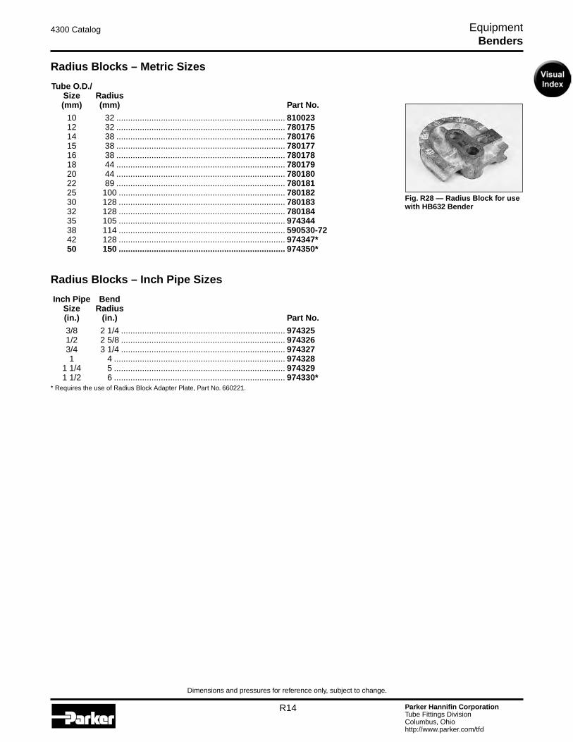
Fig. R27 — Radius Block for use with HB632 Bender
METRIC TUBE SIZES Part No.Clamp Block (for 10mm, 12mm, 14mm, 16mm) ......................... 790017Clamp Block (for 15mm, 16mm, 18mm, 20mm) ......................... 780195Clamp Block (for 22mm, 25mm, 30mm, 32mm) ......................... 780196Clamp Block (for 35mm) ............................................................. 974346Clamp Block (for 38mm) ............................................................. 631092Clamp Block (for 42mm) ............................................................. 974349Clamp Block (for 50mm) ............................................................. 974352Slide Block (for 10mm, 12mm, 14mm, 16mm) ........................... 790016Slide Block (for 15mm, 16mm, 18mm, 20mm) ........................... 780192Slide Block (for 22mm, 25mm, 30mm, 32mm) ........................... 780193Slide Block (for 35mm) ............................................................... 820094Slide Block (for 38mm) ............................................................... 520516Slide Block (for 42mm) ............................................................... 974348Slide Block (for 50mm) ............................................................... 974351
INCH PIPE SIZESClamp Block (for 3/8”, 1/2”, 3/4”) ................................................ 974332Clamp Block (for 1”) .................................................................... 974338Clamp Block (for 1 1/4”) .............................................................. 974341Clamp Block (for 1 1/2”) .............................................................. 974343Slide Block (for 3/8”, 1/2”, 3/4”) ................................................... 974331Slide Block (for 1”) ...................................................................... 974336Slide Block (for 1 1/4”) ................................................................ 974340Slide Block (for 1 1/2”) ................................................................ 974342
OPTIONAL ACCESSORIESRadius Block Adapter Plate (for sizes 1 3/4”, 42mm, 1 1/2 IPS and larger)..................... 660221Mandrel Bending Components for HB632 .................................. See pages R16 – R18 A video (on DVD) is included to provide proper instructions for use.
Radius BlocksFor use with HB632 Bender
Radius blocks for every standard tube size from size 6 (3/8” O.D.) to size 32 (2” O.D.), 10mm through 50mm, and inch pipe sizes 3/8” through 1-1/2” are available.
Standard Radius Blocks – Inch Sizes Tube O.D. Radius Size (in.) (in.) Part No.
6 3/8 1 1/8 ............................................................ 590512-18 6 3/8 1 1/4 ............................................................ 540502 8 1/2 1 1/4 ............................................................ 530763 8 1/2 1 1/2 ............................................................ 590515-24 10 5/8 1 1/2 ............................................................ 530764 10 5/8 1 7/8 ............................................................ 590518-30 12 3/4 1 3/4 ............................................................ 530765 12 3/4 2 1/4 ............................................................ 590521-36 14 7/8 2 ............................................................... 530766 14 7/8 2 5/8 ............................................................ 590523-42 16 1 3 ............................................................... 590524-48 18 1 1/8 3 3/8 ............................................................ 590526-54 18 1 1/8 3 1/2 ............................................................ 530768 20 1 1/4 3 3/4 ............................................................ 590527-60 24 1 1/2 4 1/2 ............................................................ 590530-72 24 1 1/2 5 ............................................................... 530770 28 1 3/4 7 ............................................................... 631057-112* 32 2 8 ............................................................... 631060-128*
* Requires the use of Radius Block Adapter Plate, Part No. 660221.
Fig. R26 — Radius Block Adapter Plate
Benders
Parker Hannifin CorporationTube Fittings DivisionColumbus, Ohiohttp://www.parker.com/tfd
R14
4300 Catalog Equipment
Dimensions and pressures for reference only, subject to change.
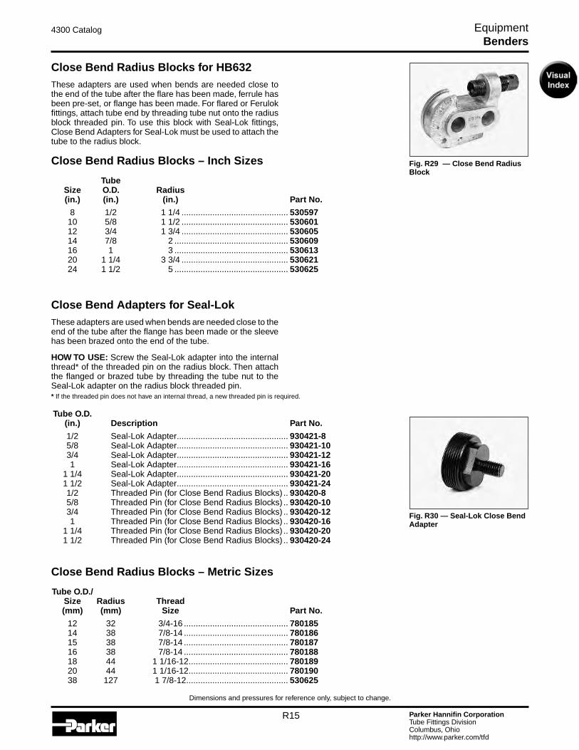
Radius Blocks – Metric Sizes Tube O.D./ Size Radius (mm) (mm) Part No.
10 32 ........................................................................ 810023 12 32 ........................................................................ 780175 14 38 ........................................................................ 780176 15 38 ........................................................................ 780177 16 38 ........................................................................ 780178 18 44 ........................................................................ 780179 20 44 ........................................................................ 780180 22 89 ........................................................................ 780181 25 100 ....................................................................... 780182 30 128 ....................................................................... 780183 32 128 ....................................................................... 780184 35 105 ....................................................................... 974344 38 114 ....................................................................... 590530-72 42 128 ....................................................................... 974347* 50 150 ....................................................................... 974350*
Radius Blocks – Inch Pipe Sizes Inch Pipe Bend Size Radius (in.) (in.) Part No.
3/8 2 1/4 ...................................................................... 974325 1/2 2 5/8 ...................................................................... 974326 3/4 3 1/4 ...................................................................... 974327 1 4 ......................................................................... 974328 1 1/4 5 ......................................................................... 974329 1 1/2 6 ......................................................................... 974330** Requires the use of Radius Block Adapter Plate, Part No. 660221.
Fig. R28 — Radius Block for use with HB632 Bender
Benders
Parker Hannifin CorporationTube Fittings DivisionColumbus, Ohiohttp://www.parker.com/tfd
R15
4300 Catalog Equipment
Dimensions and pressures for reference only, subject to change.
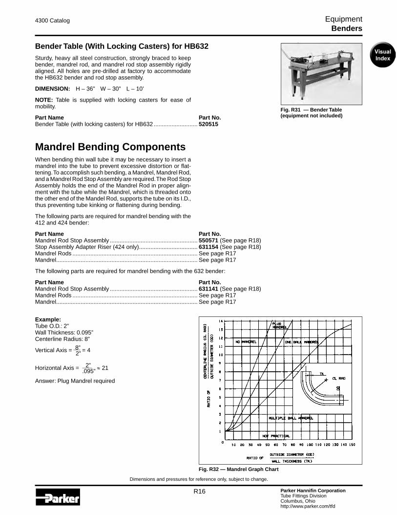
Fig. R29 — Close Bend Radius Block
Close Bend Radius Blocks for HB632These adapters are used when bends are needed close to the end of the tube after the flare has been made, ferrule has been pre-set, or flange has been made. For flared or Ferulok fittings, attach tube end by threading tube nut onto the radius block threaded pin. To use this block with Seal-Lok fittings, Close Bend Adapters for Seal-Lok must be used to attach the tube to the radius block.
Close Bend Radius Blocks – Inch Sizes Tube Size O.D. Radius (in.) (in.) (in.) Part No.
8 1/2 1 1/4 ............................................. 530597 10 5/8 1 1/2 ............................................. 530601 12 3/4 1 3/4 ............................................. 530605 14 7/8 2 ................................................ 530609 16 1 3 ................................................ 530613 20 1 1/4 3 3/4 ............................................. 530621 24 1 1/2 5 ................................................ 530625
Close Bend Adapters for Seal-LokThese adapters are used when bends are needed close to the end of the tube after the flange has been made or the sleeve has been brazed onto the end of the tube.
HOW TO USE: Screw the Seal-Lok adapter into the internal thread* of the threaded pin on the radius block. Then attach the flanged or brazed tube by threading the tube nut to the Seal-Lok adapter on the radius block threaded pin.* If the threaded pin does not have an internal thread, a new threaded pin is required. Tube O.D. (in.) Description Part No.
1/2 Seal-Lok Adapter ............................................... 930421-8 5/8 Seal-Lok Adapter ............................................... 930421-10 3/4 Seal-Lok Adapter ............................................... 930421-12 1 Seal-Lok Adapter ............................................... 930421-16 1 1/4 Seal-Lok Adapter ............................................... 930421-20 1 1/2 Seal-Lok Adapter ............................................... 930421-24 1/2 Threaded Pin (for Close Bend Radius Blocks) .. 930420-8 5/8 Threaded Pin (for Close Bend Radius Blocks) .. 930420-10 3/4 Threaded Pin (for Close Bend Radius Blocks) .. 930420-12 1 Threaded Pin (for Close Bend Radius Blocks) .. 930420-16 1 1/4 Threaded Pin (for Close Bend Radius Blocks) .. 930420-20 1 1/2 Threaded Pin (for Close Bend Radius Blocks) .. 930420-24
Close Bend Radius Blocks – Metric Sizes Tube O.D./ Size Radius Thread (mm) (mm) Size Part No.
12 32 3/4-16 ............................................ 780185 14 38 7/8-14 ............................................ 780186 15 38 7/8-14 ............................................ 780187 16 38 7/8-14 ............................................ 780188 18 44 1 1/16-12 .......................................... 780189 20 44 1 1/16-12 .......................................... 780190 38 127 1 7/8-12 ........................................... 530625
Benders
Fig. R30 — Seal-Lok Close Bend Adapter
Parker Hannifin CorporationTube Fittings DivisionColumbus, Ohiohttp://www.parker.com/tfd
R16
4300 Catalog Equipment
Dimensions and pressures for reference only, subject to change.
Fig. R31 — Bender Table (equipment not included)
Fig. R32 — Mandrel Graph Chart
Bender Table (With Locking Casters) for HB632Sturdy, heavy all steel construction, strongly braced to keep bender, mandrel rod, and mandrel rod stop assembly rigidly aligned. All holes are pre-drilled at factory to accommodate the HB632 bender and rod stop assembly.
DIMENSION: H – 36” W – 30” L – 10’
NOTE: Table is supplied with locking casters for ease of mobility.
Part Name Part No.Bender Table (with locking casters) for HB632 ........................... 520515
Mandrel Bending ComponentsWhen bending thin wall tube it may be necessary to insert a mandrel into the tube to prevent excessive distortion or flat-tening. To accomplish such bending, a Mandrel, Mandrel Rod, and a Mandrel Rod Stop Assembly are required. The Rod Stop Assembly holds the end of the Mandrel Rod in proper align-ment with the tube while the Mandrel, which is threaded onto the other end of the Mandel Rod, supports the tube on its I.D., thus preventing tube kinking or flattening during bending.
The following parts are required for mandrel bending with the 412 and 424 bender:
Part Name Part No.Mandrel Rod Stop Assembly ...................................................... 550571 (See page R18)Stop Assembly Adapter Riser (424 only) .................................... 631154 (See page R18)Mandrel Rods ............................................................................. See page R17Mandrel ....................................................................................... See page R17
The following parts are required for mandrel bending with the 632 bender:
Part Name Part No.Mandrel Rod Stop Assembly ...................................................... 631141 (See page R18)Mandrel Rods ............................................................................. See page R17Mandrel ....................................................................................... See page R17
Example:Tube O.D.: 2”Wall Thickness: 0.095”Centerline Radius: 8”
Vertical Axis = 8” = 4 2”
Horizontal Axis = 2” ≈ 21 .095”
Answer: Plug Mandrel required
Benders
Parker Hannifin CorporationTube Fittings DivisionColumbus, Ohiohttp://www.parker.com/tfd
R17
4300 Catalog Equipment
Dimensions and pressures for reference only, subject to change.
Table R4 — Mandrel Sizes
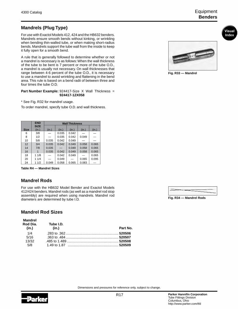
Fig. R33 — Mandrel
Fig. R34 — Mandrel Rods
Mandrels (Plug Type)For use with Exactol Models 412, 424 and the HB632 benders. Mandrels ensure smooth bends without kinking, or wrinkling when bending thin-walled tube, or when making short-radius bends. Mandrels support the tube wall from the inside to keep it fully open for a smooth bend.
A rule that is generally followed to determine whether or not a mandrel is necessary is as follows: When the wall thickness of the tube to be bent is 7 percent or more of the tube O.D., a mandrel is usually not necessary. On wall thicknesses that range between 4-6 percent of the tube O.D., it is necessary to use a mandrel to avoid wrinkling and flattening in the bend area. This rule is based on a bend radii of between three and four times the tube O.D.
Part Number Example: 924417-Size X Wall Thickness = 924417-12X058
* See Fig. R32 for mandrel usage.
To order mandrel, specify tube O.D. and wall thickness.
Mandrel RodsFor use with the HB632 Model Bender and Exactol Models 412/424 benders. Mandrel rods (as well as a mandrel rod stop assembly) are required when using mandrels. Mandrel rod diameters are determined by tube I.D.
Mandrel Rod Sizes Mandrel Rod Dia. Tube I.D. (in.) (in.) Part No.
1/4 .283 to .362 ...................................................... 520506 5/16 .363 to .484 ...................................................... 520507 13/32 .485 to 1.489 ..................................................... 520508 5/8 1.49 to 1.87 .................................................... 520509
Benders
Size
END SIZE(in.)
Wall Thickness
(in.) (in.) (in.) (in.) (in.)6 3/8 — 0.035 0.042 — —8 1/2 — 0.035 0.042 0.049 —10 5/8 0.035 0.042 0.049 — —12 3/4 0.035 0.042 0.049 0.058 0.06514 7/8 0.035 — 0.049 0.058 0.06516 1 0.035 0.042 0.049 0.058 0.06518 1 1/8 — 0.042 0.049 — 0.06520 1 1/4 — 0.049 — 0.065 0.09524 1 1/2 0.049 0.058 0.065 0.083 —
Parker Hannifin CorporationTube Fittings DivisionColumbus, Ohiohttp://www.parker.com/tfd
R18
4300 Catalog Equipment
Dimensions and pressures for reference only, subject to change.
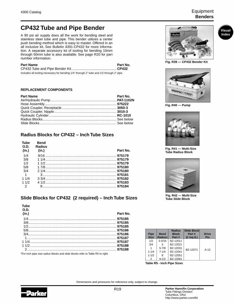
Fig. R35 — Mandrel Rod Stop Assembly /632
Fig. R36 — Mandrel Rod Stop Assembly 412/424
Fig. R37 — Stop Assembly Adapter/Riser
Fig. R38 — Universal Side Angle Indicator
Mandrel Rod Stop AssemblyFor use with Model HB632 bender.
The Mandrel Rod Stop Assembly, when bolted to the end of a table opposite of the bender, keeps the mandrel rod in align-ment with the tube when mandrel bending.
Part Name Part No.Mandrel Rod Stop Assembly (for bender Model HB632) ............ 631141
Mandrel Rod Stop AssemblyFor use with Exactol 412/424 Model benders.
Part Name Part No.Mandrel Rod Stop Assembly ...................................................... 550571
Part Name Part No.Stop Assembly Adapter/Riser for 424 ......................................... 631154
Universal Side Angle IndicatorFor use with Model HB632 bender.
Accurately determines angle between tube bends in different planes. Keeps out of plane angles accurate, when making re-peated bends. Large, easy-to-read vernier dial. Maximum 3/4” O.D. tube can be used if the tube must be extended through the indicator. Maximum 1 1/2” O.D. tube can be used if end of tube is held in clamp jaw.
Part Name Part No.Universal Side Angle Indicator ................................................... 520520
Benders
Parker Hannifin CorporationTube Fittings DivisionColumbus, Ohiohttp://www.parker.com/tfd
R19
4300 Catalog Equipment
Dimensions and pressures for reference only, subject to change.
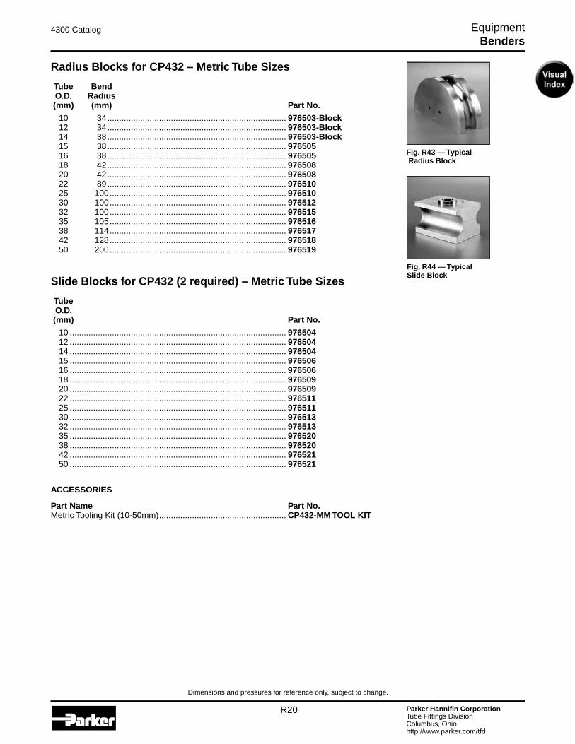
Fig. R39 — CP432 Bender Kit
Fig. R40 — Pump
Fig. R41 — Multi-Size Tube Radius Block
Fig. R42 — Multi-Size Tube Slide Block
CP432 Tube and Pipe BenderA 90 psi air supply does all the work for bending steel and stainless steel tube and pipe. This bender utilizes a center push bending method which is easy to master. Offered in an all inclusive kit. See Bulletin 4391-CP432 for more informa-tion. A separate accessory kit of tooling for bending 10mm through 50mm tube is also available. See page R20 for part number information.
Part Name Part No.CP432 Tube and Pipe Bender Kit ............................................... CP432Includes all tooling necessary for bending 1/4” thorugh 2” tube and 1/2 through 2” pipe.
REPLACEMENT COMPONENTS
Part Name Part No.Air/Hydraulic Pump ..................................................................... PAT-1102NHose Assembly ........................................................................... 975222Quick Coupler, Receptacle ......................................................... 3050-3Quick Coupler, Nipple ................................................................. 3010-3Hydraulic Cylinder ...................................................................... RC-1010Radius Blocks ............................................................................. See belowSlide Blocks ................................................................................ See below
Radius Blocks for CP432 – Inch Tube Sizes Tube Bend O.D. Radius (in.) (in.) Part No.
1/4 9/16 .......................................................................... 975179 3/8 1 1/4 .......................................................................... 975179 1/2 1 1/2 .......................................................................... 975179 5/8 1 7/8 .......................................................................... 975180 3/4 2 1/4 .......................................................................... 975180 1 3 ............................................................................. 975181 1 1/4 3 3/4 .......................................................................... 975182 1 1/2 4 1/2 .......................................................................... 975183 2 8 ............................................................................. 975184
Slide Blocks for CP432 (2 required) – Inch Tube Sizes Tube O.D. (in.) Part No.
1/4 ............................................................................................ 975185 3/8 ............................................................................................ 975185 1/2 ............................................................................................ 975185 5/8 ............................................................................................ 975186 3/4 ............................................................................................ 975186 1 ............................................................................................. 975187 1 1/4 .......................................................................................... 975187 1 1/2 .......................................................................................... 975188 2 ............................................................................................. 975188*For inch pipe size radius blocks and slide blocks refer to Table R5 to right.
Benders
PipeSize
Bend Radius)
RadiusBlockPart #
Slide BlockPart #
(2 req.’d.)DrivePin
1/2 3-3/16 BZ-12011
BZ-12071 A-12
3/4 5 BZ-120211 5-7/8 BZ-12031
1-1/4 7-1/4 BZ-120411-1/2 8 BZ-12051
2 9-1/2 BZ-12061
Table R5 - Inch Pipe Sizes
Parker Hannifin CorporationTube Fittings DivisionColumbus, Ohiohttp://www.parker.com/tfd
R20
4300 Catalog Equipment
Dimensions and pressures for reference only, subject to change.
Fig. R43 — Typical Radius Block
Fig. R44 — Typical Slide Block
Radius Blocks for CP432 – Metric Tube Sizes Tube Bend O.D. Radius (mm) (mm) Part No.
10 34 ............................................................................ 976503-Block 12 34 ............................................................................ 976503-Block 14 38 ............................................................................ 976503-Block 15 38 ............................................................................ 976505 16 38 ............................................................................ 976505 18 42 ............................................................................ 976508 20 42 ............................................................................ 976508 22 89 ............................................................................ 976510 25 100 ........................................................................... 976510 30 100 ........................................................................... 976512 32 100 ........................................................................... 976515 35 105 ........................................................................... 976516 38 114 ........................................................................... 976517 42 128 ........................................................................... 976518 50 200 ........................................................................... 976519
Benders
Slide Blocks for CP432 (2 required) – Metric Tube Sizes Tube O.D. (mm) Part No.
10 ............................................................................................ 976504 12 ............................................................................................ 976504 14 ............................................................................................ 976504 15 ............................................................................................ 976506 16 ............................................................................................ 976506 18 ............................................................................................ 976509 20 ............................................................................................ 976509 22 ............................................................................................ 976511 25 ............................................................................................ 976511 30 ............................................................................................ 976513 32 ............................................................................................ 976513 35 ............................................................................................ 976520 38 ............................................................................................ 976520 42 ............................................................................................ 976521 50 ............................................................................................ 976521
ACCESSORIES
Part Name Part No.Metric Tooling Kit (10-50mm) ...................................................... CP432-MM TOOL KIT
Parker Hannifin CorporationTube Fittings DivisionColumbus, Ohiohttp://www.parker.com/tfd
R21
4300 Catalog Equipment
Dimensions and pressures for reference only, subject to change.
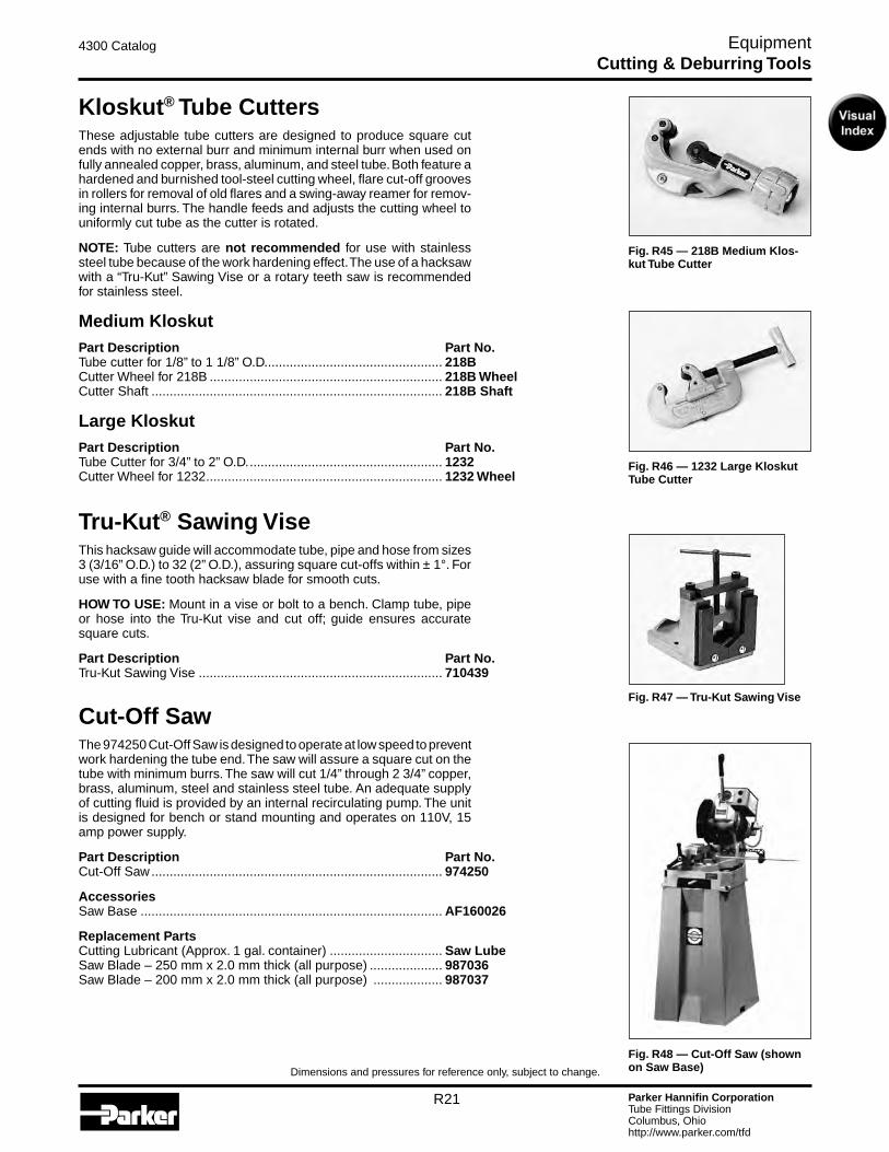
Fig. R45 — 218B Medium Klos-kut Tube Cutter
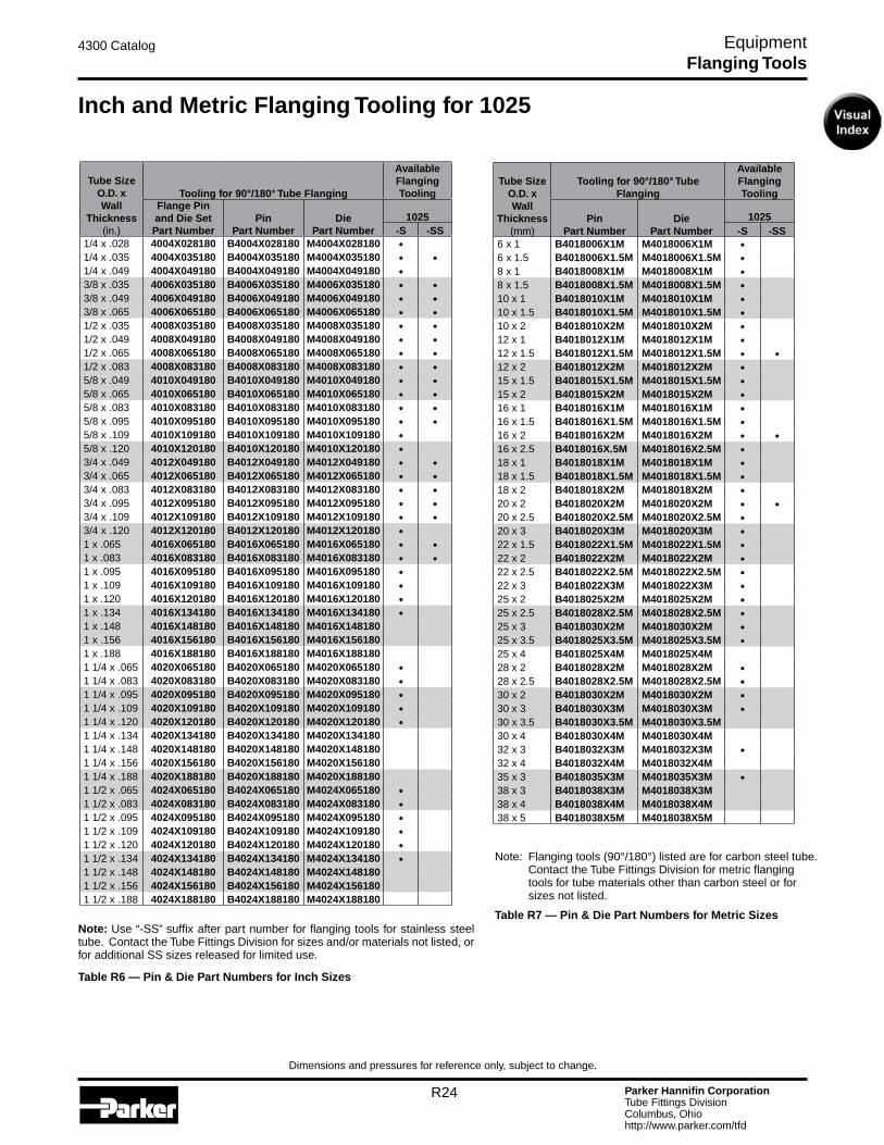
Fig. R47 — Tru-Kut Sawing Vise
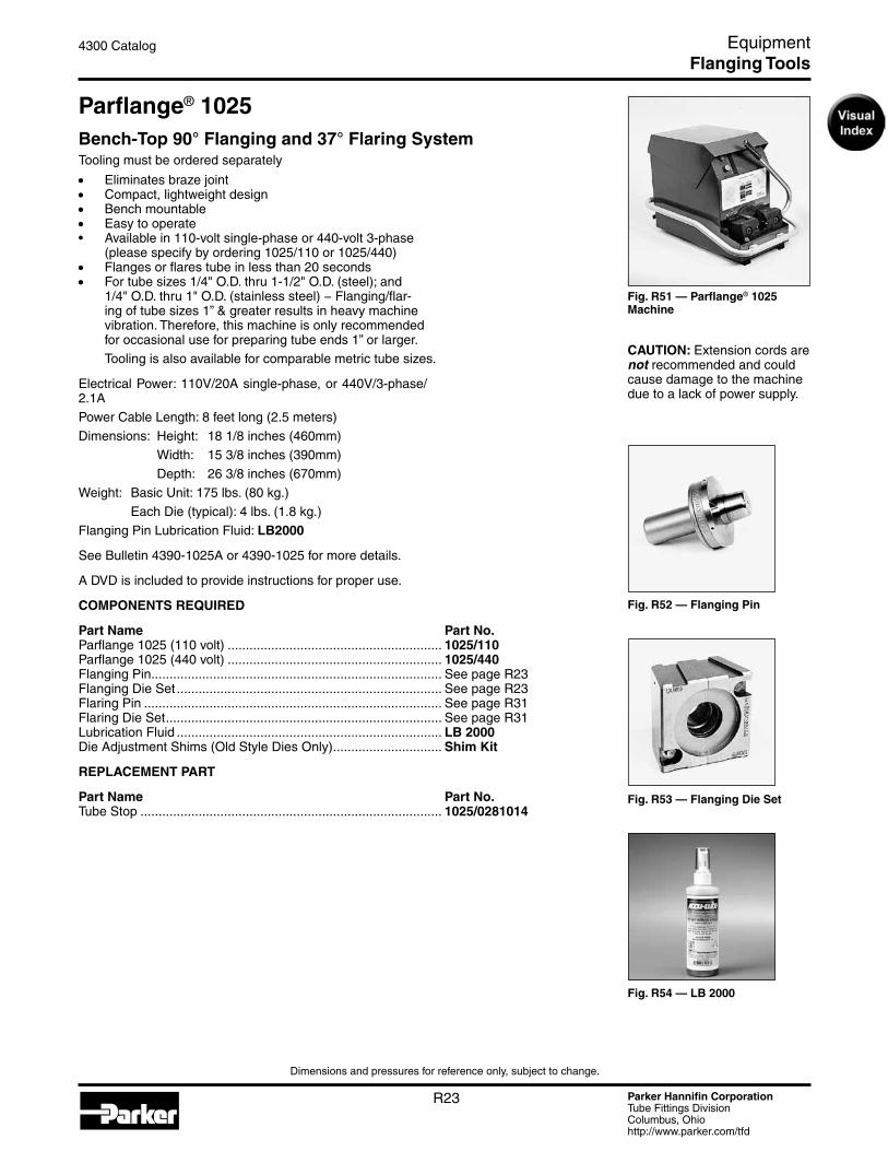
Fig. R46 — 1232 Large Kloskut Tube Cutter
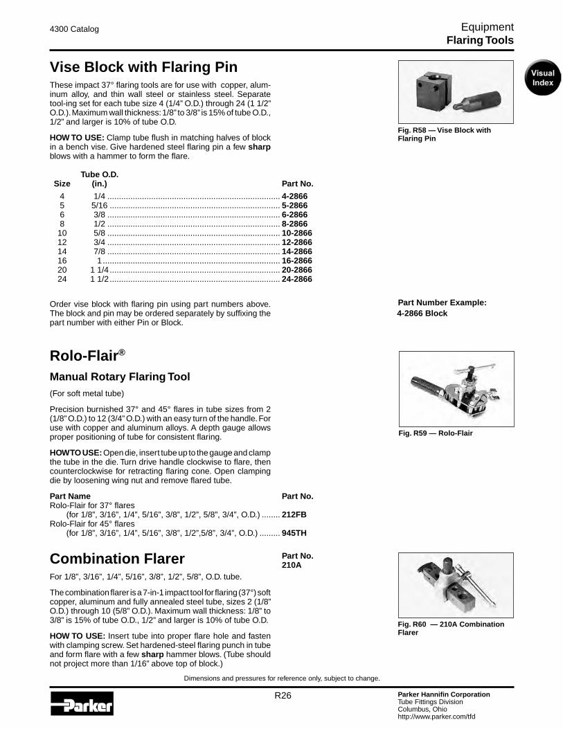
Fig. R48 — Cut-Off Saw (shown on Saw Base)
Kloskut® Tube CuttersThese adjustable tube cutters are designed to produce square cut ends with no external burr and minimum internal burr when used on fully annealed copper, brass, aluminum, and steel tube. Both feature a hardened and burnished tool-steel cutting wheel, flare cut-off grooves in rollers for removal of old flares and a swing-away reamer for remov-ing internal burrs. The handle feeds and adjusts the cutting wheel to uniformly cut tube as the cutter is rotated.
NOTE: Tube cutters are not recommended for use with stainless steel tube because of the work hardening effect. The use of a hacksaw with a “Tru-Kut” Sawing Vise or a rotary teeth saw is recommended for stainless steel.
Medium KloskutPart Description Part No.Tube cutter for 1/8” to 1 1/8” O.D. ................................................ 218BCutter Wheel for 218B ................................................................ 218B WheelCutter Shaft ................................................................................ 218B Shaft
Large KloskutPart Description Part No.Tube Cutter for 3/4” to 2” O.D. ..................................................... 1232Cutter Wheel for 1232 ................................................................. 1232 Wheel
Tru-Kut® Sawing ViseThis hacksaw guide will accommodate tube, pipe and hose from sizes 3 (3/16” O.D.) to 32 (2” O.D.), assuring square cut-offs within ± 1°. For use with a fine tooth hacksaw blade for smooth cuts.
HOW TO USE: Mount in a vise or bolt to a bench. Clamp tube, pipe or hose into the Tru-Kut vise and cut off; guide ensures accurate square cuts.
Part Description Part No.Tru-Kut Sawing Vise ................................................................... 710439
Cut-Off SawThe 974250 Cut-Off Saw is designed to operate at low speed to prevent work hardening the tube end. The saw will assure a square cut on the tube with minimum burrs. The saw will cut 1/4” through 2 3/4” copper, brass, aluminum, steel and stainless steel tube. An adequate supply of cutting fluid is provided by an internal recirculating pump. The unit is designed for bench or stand mounting and operates on 110V, 15 amp power supply.
Part Description Part No.Cut-Off Saw ................................................................................ 974250
AccessoriesSaw Base ................................................................................... AF160026
Replacement PartsCutting Lubricant (Approx. 1 gal. container) ............................... Saw LubeSaw Blade – 250 mm x 2.0 mm thick (all purpose) .................... 987036Saw Blade – 200 mm x 2.0 mm thick (all purpose) ................... 987037
Cutting & Deburring Tools

Parker Hannifin CorporationTube Fittings DivisionColumbus, Ohiohttp://www.parker.com/tfd
R22
4300 Catalog Equipment
Dimensions and pressures for reference only, subject to change.
Fig. R49 — 226A In-Ex Deburr Tool
Fig. R50 — Power Deburr Tool
In-Ex® Tube Deburring Tool 226AA quick twist of the wrist will deburr either the O.D. or the I.D. of the tube end. Parker’s In-Ex deburrer can be used on an-nealed steel, stainless steel, copper and aluminum, for tube sizes 1/8” to 1 5/8” O.D.
Part Description Part No.In-Ex Deburring Tool ................................................................... 226ABlade Set for 226A Tube Deburr Tool .......................................... 226A Blades
Power Deburr ToolThe Parker Power Deburr Tool is designed for deburring the I.D. and O.D. of 1/4” through 2” steel, stainless steel, copper and aluminum tube. The lightweight unit incorporates a modu-lar design which allows Parker’s Cut-Off Saw, part number 974250, to be easily mounted on the top. The Power Deburr Tool requires 110V/10A power supply.
Dimensions: L – 20”, W – 18”, H – 9”.
Part Description Part No.Power Deburr Tool ...................................................................... 972125
Replacement PartsI.D. Deburr Cone ......................................................................... 971816O.D. Deburr Blades (six blade set).............................................. 910485
Cutting & Deburring Tools
Parker Hannifin CorporationTube Fittings DivisionColumbus, Ohiohttp://www.parker.com/tfd
R23
4300 Catalog Equipment
Dimensions and pressures for reference only, subject to change.
Fig. R51 — Parflange® 1025 Machine
Fig. R52 — Flanging Pin
Fig. R54 — LB 2000
CAUTION: Extension cords are not recommended and could cause damage to the machine due to a lack of power supply.
Fig. R53 — Flanging Die Set
Parflange® 1025Bench-Top 90° Flanging and 37° Flaring SystemTooling must be ordered separately
• Eliminates braze joint• Compact, lightweight design• Bench mountable• Easy to operate• Availablein110-voltsingle-phaseor440-volt3-phase
(please specify by ordering 1025/110 or 1025/440)• Flanges or flares tube in less than 20 seconds• For tube sizes 1/4" O.D. thru 1-1/2" O.D. (steel); and
1/4" O.D. thru 1" O.D. (stainless steel) − Flanging/flar-ing of tube sizes 1” & greater results in heavy machine vibration. Therefore, this machine is only recommended for occasional use for preparing tube ends 1” or larger.
Tooling is also available for comparable metric tube sizes.
Electrical Power: 110V/20A single-phase, or 440V/3-phase/2.1APower Cable Length: 8 feet long (2.5 meters)Dimensions: Height: 18 1/8 inches (460mm) Width: 15 3/8 inches (390mm) Depth: 26 3/8 inches (670mm)Weight: Basic Unit: 175 lbs. (80 kg.) Each Die (typical): 4 lbs. (1.8 kg.)Flanging Pin Lubrication Fluid: LB2000
See Bulletin 4390-1025A or 4390-1025 for more details.
A DVD is included to provide instructions for proper use.
COMPONENTS REQUIRED
Part Name Part No.Parflange 1025 (110 volt) ........................................................... 1025/110Parflange 1025 (440 volt) ........................................................... 1025/440Flanging Pin ................................................................................ See page R23Flanging Die Set ......................................................................... See page R23Flaring Pin .................................................................................. See page R31Flaring Die Set ............................................................................ See page R31Lubrication Fluid ......................................................................... LB 2000Die Adjustment Shims (Old Style Dies Only) .............................. Shim Kit
REPLACEMENT PART
Part Name Part No.Tube Stop ................................................................................... 1025/0281014
Flanging Tools
Parker Hannifin CorporationTube Fittings DivisionColumbus, Ohiohttp://www.parker.com/tfd
R24
4300 Catalog Equipment
Dimensions and pressures for reference only, subject to change.
Tube Size O.D. xWall
Thickness (in.)
Tooling for 90°/180° Tube Flanging
Available Flanging Tooling
Flange Pin and Die SetPart Number
PinPart Number
DiePart Number
1025-S -SS
1/4 x .028 4004X028180 B4004X028180 M4004X028180 ·1/4 x .035 4004X035180 B4004X035180 M4004X035180 · ·1/4 x .049 4004X049180 B4004X049180 M4004X049180 ·3/8 x .035 4006X035180 B4006X035180 M4006X035180 · ·3/8 x .049 4006X049180 B4006X049180 M4006X049180 · ·3/8 x .065 4006X065180 B4006X065180 M4006X065180 · ·1/2 x .035 4008X035180 B4008X035180 M4008X035180 · ·1/2 x .049 4008X049180 B4008X049180 M4008X049180 · ·1/2 x .065 4008X065180 B4008X065180 M4008X065180 · ·1/2 x .083 4008X083180 B4008X083180 M4008X083180 · ·5/8 x .049 4010X049180 B4010X049180 M4010X049180 · ·5/8 x .065 4010X065180 B4010X065180 M4010X065180 · ·5/8 x .083 4010X083180 B4010X083180 M4010X083180 · ·5/8 x .095 4010X095180 B4010X095180 M4010X095180 · ·5/8 x .109 4010X109180 B4010X109180 M4010X109180 ·5/8 x .120 4010X120180 B4010X120180 M4010X120180 ·3/4 x .049 4012X049180 B4012X049180 M4012X049180 · ·3/4 x .065 4012X065180 B4012X065180 M4012X065180 · ·3/4 x .083 4012X083180 B4012X083180 M4012X083180 · ·3/4 x .095 4012X095180 B4012X095180 M4012X095180 · ·3/4 x .109 4012X109180 B4012X109180 M4012X109180 · ·3/4 x .120 4012X120180 B4012X120180 M4012X120180 ·1 x .065 4016X065180 B4016X065180 M4016X065180 · ·1 x .083 4016X083180 B4016X083180 M4016X083180 · ·1 x .095 4016X095180 B4016X095180 M4016X095180 ·1 x .109 4016X109180 B4016X109180 M4016X109180 ·1 x .120 4016X120180 B4016X120180 M4016X120180 ·1 x .134 4016X134180 B4016X134180 M4016X134180 ·1 x .148 4016X148180 B4016X148180 M4016X1481801 x .156 4016X156180 B4016X156180 M4016X1561801 x .188 4016X188180 B4016X188180 M4016X1881801 1/4 x .065 4020X065180 B4020X065180 M4020X065180 ·1 1/4 x .083 4020X083180 B4020X083180 M4020X083180 ·1 1/4 x .095 4020X095180 B4020X095180 M4020X095180 ·1 1/4 x .109 4020X109180 B4020X109180 M4020X109180 ·1 1/4 x .120 4020X120180 B4020X120180 M4020X120180 ·1 1/4 x .134 4020X134180 B4020X134180 M4020X1341801 1/4 x .148 4020X148180 B4020X148180 M4020X1481801 1/4 x .156 4020X156180 B4020X156180 M4020X1561801 1/4 x .188 4020X188180 B4020X188180 M4020X1881801 1/2 x .065 4024X065180 B4024X065180 M4024X065180 ·1 1/2 x .083 4024X083180 B4024X083180 M4024X083180 ·1 1/2 x .095 4024X095180 B4024X095180 M4024X095180 ·1 1/2 x .109 4024X109180 B4024X109180 M4024X109180 ·1 1/2 x .120 4024X120180 B4024X120180 M4024X120180 ·1 1/2 x .134 4024X134180 B4024X134180 M4024X134180 ·1 1/2 x .148 4024X148180 B4024X148180 M4024X1481801 1/2 x .156 4024X156180 B4024X156180 M4024X1561801 1/2 x .188 4024X188180 B4024X188180 M4024X188180
Table R6 — Pin & Die Part Numbers for Inch Sizes
Note: Use “-SS” suffix after part number for flanging tools for stainless steel tube. Contact the Tube Fittings Division for sizes and/or materials not listed, or for additional SS sizes released for limited use.
Table R7 — Pin & Die Part Numbers for Metric Sizes
Note: Flanging tools (90°/180°) listed are for carbon steel tube. Contact the Tube Fittings Division for metric flanging tools for tube materials other than carbon steel or for sizes not listed.
Inch and Metric Flanging Tooling for 1025
Flanging Tools
Tube Size O.D. xWall
Thickness(mm)
Tooling for 90°/180° Tube Flanging
Available Flanging Tooling
PinPart Number
DiePart Number
1025-S -SS
6 x 1 B4018006X1M M4018006X1M ·6 x 1.5 B4018006X1.5M M4018006X1.5M ·8 x 1 B4018008X1M M4018008X1M ·8 x 1.5 B4018008X1.5M M4018008X1.5M ·10 x 1 B4018010X1M M4018010X1M ·10 x 1.5 B4018010X1.5M M4018010X1.5M ·10 x 2 B4018010X2M M4018010X2M ·12 x 1 B4018012X1M M4018012X1M ·12 x 1.5 B4018012X1.5M M4018012X1.5M · ·12 x 2 B4018012X2M M4018012X2M ·15 x 1.5 B4018015X1.5M M4018015X1.5M ·15 x 2 B4018015X2M M4018015X2M ·16 x 1 B4018016X1M M4018016X1M ·16 x 1.5 B4018016X1.5M M4018016X1.5M ·16 x 2 B4018016X2M M4018016X2M · ·16 x 2.5 B4018016X.5M M4018016X2.5M ·18 x 1 B4018018X1M M4018018X1M ·18 x 1.5 B4018018X1.5M M4018018X1.5M ·18 x 2 B4018018X2M M4018018X2M ·20 x 2 B4018020X2M M4018020X2M · ·20 x 2.5 B4018020X2.5M M4018020X2.5M ·20 x 3 B4018020X3M M4018020X3M ·22 x 1.5 B4018022X1.5M M4018022X1.5M ·22 x 2 B4018022X2M M4018022X2M ·22 x 2.5 B4018022X2.5M M4018022X2.5M ·22 x 3 B4018022X3M M4018022X3M ·25 x 2 B4018025X2M M4018025X2M ·25 x 2.5 B4018028X2.5M M4018028X2.5M ·25 x 3 B4018030X2M M4018030X2M ·25 x 3.5 B4018025X3.5M M4018025X3.5M ·25 x 4 B4018025X4M M4018025X4M28 x 2 B4018028X2M M4018028X2M ·28 x 2.5 B4018028X2.5M M4018028X2.5M ·30 x 2 B4018030X2M M4018030X2M ·30 x 3 B4018030X3M M4018030X3M ·30 x 3.5 B4018030X3.5M M4018030X3.5M30 x 4 B4018030X4M M4018030X4M32 x 3 B4018032X3M M4018032X3M ·32 x 4 B4018032X4M M4018032X4M35 x 3 B4018035X3M M4018035X3M ·38 x 3 B4018038X3M M4018038X3M38 x 4 B4018038X4M M4018038X4M38 x 5 B4018038X5M M4018038X5M

Parker Hannifin CorporationTube Fittings DivisionColumbus, Ohiohttp://www.parker.com/tfd
R25
4300 Catalog Equipment
Dimensions and pressures for reference only, subject to change.
Fig. R57 — Flaring Pin
Fig. R56 — Pre-Flaring Pins
Fig. R55 — Vise Block
Manual Flaring Tool Vise Block and Flaring Pin — Metric TubeThese 37° flaring tools are designed for use in a vise when flaring metric tube from 6mm O.D. to 38mm O.D.
From 20mm size tube and upward it is necessary to use a pre-flaring pin to start the flare.• Clamp tube flush in black halves• Flaretubebyhammeringtheflaringpin.
A separate block and pin set is used for each tube size.
Pre-Flaring Pins Tube O.D. (mm) Part No.
20 ......................................................................................... P1E 25 ......................................................................................... P1E 30 ......................................................................................... P1E 32 ......................................................................................... P1E 38 ......................................................................................... P1E
Flaring Pins Tube O.D. (mm) Part No.
6 .......................................................................................... P17408 8 .......................................................................................... P17408 10 ......................................................................................... P17408 12 ......................................................................................... P17414 14 ......................................................................................... P17414 15 ......................................................................................... P17414 16 ......................................................................................... P17414 18 ......................................................................................... P17418 20 ......................................................................................... P17418 25 ......................................................................................... P17422 30 ......................................................................................... P17432 32 ......................................................................................... P17432 38 ......................................................................................... P17438
Vise Blocks Tube O.D. (mm) Part No.
6 .......................................................................................... M27406 8 .......................................................................................... M27408 10 ......................................................................................... M27410 12 ......................................................................................... M27412 14 ......................................................................................... M27414 15 ......................................................................................... M27415 16 ......................................................................................... M27416 18 ......................................................................................... M27418 20 ......................................................................................... M27420 25 ......................................................................................... M27425 30 ......................................................................................... M27430 32 ......................................................................................... M27432 38 ......................................................................................... M27438
Flaring Tools
Parker Hannifin CorporationTube Fittings DivisionColumbus, Ohiohttp://www.parker.com/tfd
R26
4300 Catalog Equipment
Dimensions and pressures for reference only, subject to change.
Vise Block with Flaring PinThese impact 37° flaring tools are for use with copper, alum-inum alloy, and thin wall steel or stainless steel. Separate tool-ing set for each tube size 4 (1/4” O.D.) through 24 (1 1/2” O.D.). Maximum wall thickness: 1/8” to 3/8” is 15% of tube O.D., 1/2” and larger is 10% of tube O.D.
HOW TO USE: Clamp tube flush in matching halves of block in a bench vise. Give hardened steel flaring pin a few sharp blows with a hammer to form the flare. Tube O.D. Size (in.) Part No.
4 1/4 ........................................................................... 4-2866 5 5/16 .......................................................................... 5-2866 6 3/8 ........................................................................... 6-2866 8 1/2 ........................................................................... 8-2866 10 5/8 ........................................................................... 10-2866 12 3/4 ........................................................................... 12-2866 14 7/8 ........................................................................... 14-2866 16 1 ............................................................................. 16-2866 20 1 1/4 .......................................................................... 20-2866 24 1 1/2 .......................................................................... 24-2866
Order vise block with flaring pin using part numbers above.The block and pin may be ordered separately by suffixing the part number with either Pin or Block.
Rolo-Flair®
Manual Rotary Flaring Tool(For soft metal tube)
Precision burnished 37° and 45° flares in tube sizes from 2 (1/8” O.D.) to 12 (3/4” O.D.) with an easy turn of the handle. For use with copper and aluminum alloys. A depth gauge allows proper positioning of tube for consistent flaring.
HOW TO USE: Open die, insert tube up to the gauge and clamp the tube in the die. Turn drive handle clockwise to flare, then counterclockwise for retracting flaring cone. Open clamping die by loosening wing nut and remove flared tube.
Part Name Part No.Rolo-Flair for 37° flares (for 1/8”, 3/16”, 1/4”, 5/16”, 3/8”, 1/2”, 5/8”, 3/4”, O.D.) ........ 212FBRolo-Flair for 45° flares (for 1/8”, 3/16”, 1/4”, 5/16”, 3/8”, 1/2”,5/8”, 3/4”, O.D.) ......... 945TH
Fig. R59 — Rolo-Flair
Flaring Tools
Fig. R60 — 210A Combination Flarer
Fig. R58 — Vise Block with Flaring Pin
Combination Flarer
For 1/8”, 3/16”, 1/4”, 5/16”, 3/8”, 1/2”, 5/8”, O.D. tube.
The combination flarer is a 7-in-1 impact tool for flaring (37°) soft copper, aluminum and fully annealed steel tube, sizes 2 (1/8” O.D.) through 10 (5/8” O.D.). Maximum wall thickness: 1/8” to 3/8” is 15% of tube O.D., 1/2” and larger is 10% of tube O.D.
HOW TO USE: Insert tube into proper flare hole and fasten with clamping screw. Set hardened-steel flaring punch in tube and form flare with a few sharp hammer blows. (Tube should not project more than 1/16” above top of block.)
4-2866 BlockPart Number Example:
Part No. 210A

Parker Hannifin CorporationTube Fittings DivisionColumbus, Ohiohttp://www.parker.com/tfd
R27
4300 Catalog Equipment
Dimensions and pressures for reference only, subject to change.
Fig. R61 — Hydra-Tool
Fig. R62 — Electric Pump
Fig. R63 — Hand Pump
Fig. R64 — Flaring Cone
Fig. R65 — Die Ring
Hydra-ToolHydraulic Flaring and Pre-Setting ToolFlaring
An efficient dependable device for 37° and 45° flaring of steel, stainless steel and copper tube. This task is made easy through hydraulic power provided by a hand or electric pump. The equipment is portable and easy to use.
This tool accommodates dies for tubes ranging in inch sizes from 4 through 32 (1/4” through 2” outside diameters) with wall thicknesses as great as .134”, and metric sizes from 6mm through 50mm. The hydraulic “push” of the Hydra-Tool flares the tube to a 37° flare angle. A gauge can be provided to enable the operator to determine the pressure required to adequately flare any given material and wall thickness of the tube. Com-plete instructions are included with the Hydra-Tool. See bulletin 4392-B10. See the following for Hydra-Tool basic unit or kit, and choice of power sources and necessary tooling.
NOTE: Flaring die sets and other tooling are available in non-standard sizes upon request from the factory.
See Appendix for flaring pressures.
COMPONENTS REQUIRED
Part Name Part No.*Hydra-Tool (basic unit) .............................................................. 710400B*Hydra-Tool Male Adapter .......................................................... 6-8 F5OLO-S*“T” Adapter for Gauge ............................................................... 6 R6LO-S*Hose Assembly (for hand or electric pumps) ............................ 910004*Adapter for Gauge ..................................................................... 6 G6L-S*Pressure Gauge (0 - 10,000 psi) ............................................... 900044Electric Hydraulic Pump (10,000 psi; 1/2 hp; 40-125 volt) .......... 900085Hand Hydraulic Pump (10,000 psi; 2 speed) .............................. 900086Die Ring (1/4” - 1 1/4”) (6mm - 32mm) ....................................... 710416ADie Ring (1 1/2” - 2”) (35mm - 50mm) ........................................ 71041237° Flaring Cone (1/4” - 1 1/4”) (6mm - 32mm) .......................... 71041937° Flaring Cone (1 1/2” - 2”) (35mm - 50mm) ........................... 710411Die Retainer Assembly (1/4” - 1 1/4”) (6mm - 32mm) ................. 710424-1Die Retainer Assembly (1 1/2” - 2”) (35mm - 50mm) .................. 710424-2Flaring Die Sets .......................................................................... See pages R28 – R29*Lubricant ................................................................................... STP**45° Flaring Cone (1/4” - 1”) ......................................................... 910312
*Included in Hydra-tool kit (Part 720370B-3)** STP Lubricant is the only lubricant recommended for use with Hydra-Tool.
Hydra-Tool KitPart Name Part No.Hydra-Tool Kit (for use with electric or hand pump) .................... 720370B-3 Includes basic unit, gauge adapter, Hydra-Tool connector, lubricant, “T” adapter, carrying case, hose assembly, operation manual and video.
Fig. R66 — Die Retainer
Flaring Tools
Fig. R67— Hydra-Tool Kit
Parker Hannifin CorporationTube Fittings DivisionColumbus, Ohiohttp://www.parker.com/tfd
R28
4300 Catalog Equipment
Dimensions and pressures for reference only, subject to change.
Fig. R68 — Flaring Die Set
Hydra-Tool 37° Flaring Die Sets for Steel – Inch Tube O.D. Size (in.) Part No.
4 1/4 ........................................................................... 710417-4 5 5/16 .......................................................................... 710417-5 6 3/8 ........................................................................... 710417-6 8 1/2 ........................................................................... 710417-8 10 5/8 ........................................................................... 710417-10 12 3/4 ........................................................................... 710417-12 14 7/8 ........................................................................... 710417-14 16 1 ............................................................................. 710417-16 20 1 1/4 .......................................................................... 710417-20 24 1 1/2 .......................................................................... 710415-24 32 2 ............................................................................. 710415-32
Hydra-Tool 37° Flaring Die Sets for Stainless Steel – Inch Tube O.D. Size (in.) Part No.
4 1/4 ........................................................................... 710417-4 SS 5 5/16 .......................................................................... 710417-5 SS* 6 3/8 ........................................................................... 710417-6 SS 8 1/2 ........................................................................... 710417-8 SS 10 5/8 ........................................................................... 710417-10 SS 12 3/4 ........................................................................... 710417-12 SS 14 7/8 ........................................................................... 710417-14 SS* 16 1 ............................................................................. 710417-16 SS 20 1 1/4 .......................................................................... 710417-20 SS 24 1 1/2 .......................................................................... 710415-24 SS 32 2 ............................................................................. 710415-32 SS
* Non-standard.
Hydra-Tool 37° Flaring Die Sets – Metric Tube O.D./ Size (mm) Part No.
6 ......................................................................................... 770106-6 8 ......................................................................................... 770106-8 10 ........................................................................................ 770106-10 12 ........................................................................................ 770106-12 15 ........................................................................................ 770106-15 16 ........................................................................................ 770106-16 18 ........................................................................................ 770106-18 20 ........................................................................................ 770106-20 22 ........................................................................................ 770106-22 25 ........................................................................................ 770106-25 28 ........................................................................................ 770106-28 30 ........................................................................................ 770106-30 32 ........................................................................................ 770106-32 35 ........................................................................................ 770095-35 38 ........................................................................................ 770095-38 42 ........................................................................................ 770095-42 50 ........................................................................................ 770095-50
Flaring Tools
Parker Hannifin CorporationTube Fittings DivisionColumbus, Ohiohttp://www.parker.com/tfd
R29
4300 Catalog Equipment
Dimensions and pressures for reference only, subject to change.
Hydra-Tool 45° Flaring Die Sets – Inch Tube O.D. Size (in.) Part No.
4 1/4 ........................................................................... 977420-4 6 3/8 ........................................................................... 977420-6 8 1/2 ........................................................................... 977420-8 10 5/8 ........................................................................... 977420-10 12 3/4 ........................................................................... 977420-12 14 7/8 ........................................................................... 977420-14 16 1 ............................................................................. 977420-16
REPLACEMENT PART
Part Name Part No.Tube Stop Assembly ................................................................... 710420B
OPTIONAL ACCESSORIES
Part Name Part No.Hydra-Tool Carrying Case .......................................................... 720377 Sturdy wood case for Hydra-Tool and tooling. (Hydra-Tool Kit is shipped in this carrying case.)
Flaring Tools
Fig. R69 — Carrying Case
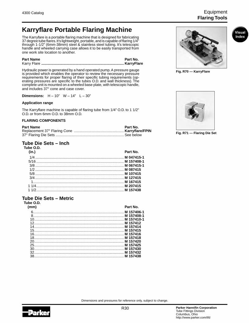
Parker Hannifin CorporationTube Fittings DivisionColumbus, Ohiohttp://www.parker.com/tfd
R30
4300 Catalog Equipment
Dimensions and pressures for reference only, subject to change.
Karryflare Portable Flaring MachineThe Karryfare is a portable flaring machine that is designed for fabricating 37 degree tube flares. It’s lightweight, portable, and is capable of flaring 1/4” through 1-1/2” (6mm-38mm) steel & stainless steel tubing. It’s telescopic handle and wheeled carrying case allows it to be easily transported from one work site location to another.
Part Name Part No.Karry Flare ................................................................................. KarryFlare
Hydraulic power is generated by a hand operated pump. A pressure gauge is provided which enables the operator to review the necessary pressure requirements for proper flaring of their specific tubing requirements (op-erating pressures are specific to the tubes O.D. and wall thickness). The complete unit is mounted on a wheeled base plate, with telescopic handle, and includes 37° cone and case cover.
Dimensions: H – 10” W – 14” L – 30”
Application range
The Karryflare machine is capable of flaring tube from 1/4” O.D. to 1 1/2” O.D. or from 6mm O.D. to 38mm O.D.
FLARING COMPONENTS
Part Name Part No.Replacement 37° Flaring Cone ................................................. Karryflare/FPIN37° Flaring Die Sets ................................................................... See below
Tube Die Sets – Inch Tube O.D. (in.) Part No.
1/4 ....................................................................................... M 047415-1 5/16 ...................................................................................... M 157408-1 3/8 ....................................................................................... M 067415-1 1/2 ....................................................................................... M 087415 5/8 ....................................................................................... M 107415 3/4 ....................................................................................... M 127415 1 ......................................................................................... M 167415 1 1/4 ...................................................................................... M 207415 1 1/2 ...................................................................................... M 157438
Tube Die Sets – Metric Tube O.D. (mm) Part No. 6 ......................................................................................... M 157406-1 8 ......................................................................................... M 157408-1 10 ........................................................................................ M 157410-1 12 ........................................................................................ M 157412 14 ........................................................................................ M 157414 15 ........................................................................................ M 157415 16 ........................................................................................ M 157416 18 ........................................................................................ M 157418 20 ........................................................................................ M 157420 25 ........................................................................................ M 157425 30 ........................................................................................ M 157430 32 ........................................................................................ M 157432 38 ........................................................................................ M 157438
Fig. R71 — Flaring Die Set
Fig. R70 — KarryFlare
Flaring Tools

Parker Hannifin CorporationTube Fittings DivisionColumbus, Ohiohttp://www.parker.com/tfd
R31
4300 Catalog Equipment
Dimensions and pressures for reference only, subject to change.
Parflange® 1025 37° Flaring and Flanging SystemsParker’s Parflange 1025 machine is designed to create 37° flared tube ends. For more detailed information on the machine and part numbers, refer to page R23.
Fig. R72 — Parflange 1025
Inch and Metric Flaring Tooling for 1025
Flaring Tools
Table R8 — Parflange Flaring Tooling for Inch Sizes
Tooling suitable for 37°/74° flaring of steel, stainless steel, aluminum, monel, copper, and cupro-nickel tube materials. For 37°/74° flaring, one die covers each tube O.D.; a different pin is required for each tube wall. Setscrews in flaring dies may require slight adjustment for different tube materials and/or tube walls.
Fig. R73 — Flaring Pin Fig. R74— Flaring Die
Table R9 — Parflange Flaring Tooling for Metric Sizes
Tooling suitable for 37°/74° flaring of steel, stainless steel, aluminum, monel, copper, and cupro-nickel tube materials. Apply LB 2000 lube to flaring pin. Setscrews in flaring dies may require slight adjustment for different tube materials and/or tube walls.
Tube Size O.D. x Wall Thickness
(in.)
Tooling for 37°/74° Tube Flaring
Available Flaring Tooling
PinPart Number
DiePart Number 1025
1/4 x .020 B4004X020074 M4004074 ·1/4 x .028 B4004X028074 M4004074 ·1/4 x .035 B4004X035074 M4004074 ·1/4 x .049 B4004X049074 M4004074 ·1/4 x .065 B4004X065074 M4004074 ·3/8 x .020 B4006X020074 M4006074 ·3/8 x .028 B4006X028074 M4006074 ·3/8 x .035 B4006X035074 M4006074 ·3/8 x .049 B4006X049074 M4006074 ·3/8 x .065 B4006X065074 M4006074 ·1/2 x .028 B4008X028074 M4008074 ·1/2 x .035 B4008X035074 M4008074 ·1/2 x .049 B4008X049074 M4008074 ·1/2 x .065 B4008X065074 M4008074 ·1/2 x .083 B4008X083074 M4008074 ·5/8 x .035 B4010X035074 M4010074 ·5/8 x .049 B4010X049074 M4010074 ·5/8 x .065 B4010X065074 M4010074 ·5/8 x .083 B4010X083074 M4010074 ·5/8 x .095 B4010X095074 M4010074 ·3/4 x .035 B4012X035074 M4012074 ·3/4 x .049 B4012X049074 M4012074 ·3/4 x .065 B4012X065074 M4012074 ·3/4 x .083 B4012X083074 M4012074 ·3/4 x .095 B4012X095074 M4012074 ·3/4 x .109 B4012X109074 M4012074 ·1 x .035 B4016X035074 M4016074 ·1 x .049 B4016X049074 M4016074 ·1 x .065 B4016X065074 M4016074 ·1 x .083 B4016X083074 M4016074 ·1 x .095 B4016X095074 M4016074 ·1 x .109 B4016X109074 M4016074 ·1 x .120 B4016X120074 M4016074 ·1 1/4 x .049 B4020X049074 M4020074 ·1 1/4 x .065 B4020X065074 M4020074 ·1 1/4 x .083 B4020X083074 M4020074 ·1 1/4 x .095 B4020X095074 M4020074 ·1 1/4 x .109 B4020X109074 M4020074 ·1 1/4 x .120 B4020X120074 M4020074 ·1 1/2 x .065 B4024X065074 M4024074 ·1 1/2 x .083 B4024X083074 M4024074 ·1 1/2 x .095 B4024X095074 M4024074 ·1 1/2 x .109 B4024X109074 M4024074 ·1 1/2 x .120 B4024X120074 M4024074 ·
Tube Size O.D. x Wall Thickness
(mm)
Tooling for 37°/74° Tube Flaring
Available Flaring Tooling
PinPart Number
DiePart Number 1025
6 x 1 B4007406X1M M4007406M ·6 x 1.5 B4007406X1.5M M4007406M ·8 x 1 B4007408X1M M4007408M ·8 x 1.5 B4007408X1.5M M4007408M ·10 x 1 B4007410X1M M4007410M ·10 x 1.5 B4007410X1.5M M4007410M ·12 x 1.5 B4007412X1.5M M4007412M ·12 x 2 B4007412X2M M4007412M ·15 x 1.5 B4007415X1.5M M4007415M ·15 x 2 B4007415X2M M4007415M ·16 x 1.5 B4007416X1.5M M4007416M ·16 x 2 B4007416X2M M4007416M ·18 x 2 B4007418X2M M4007418M ·20 x 2 B4007420X2M M4007420M ·20 x 2.5 B4007420X2.5M M4007420M ·25 x 2 B4007425X2M M4007425M ·25 x 2.5 B4007425X2.5M M4007425M ·25 x 3 B4007425X3M M4007425M ·30 x 2.5 B4007430X2.5M M4007430M ·30 x 3 B4007430X3M M4007430M ·32 x 3 B4007432X3M M4007432M ·38 x 3 B4007438X3M M4007438M ·38 x 4 B4007438X4M M4007438M
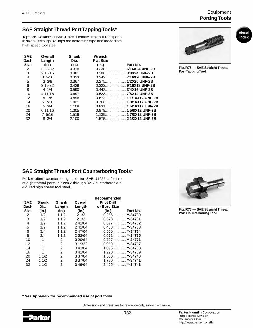
Parker Hannifin CorporationTube Fittings DivisionColumbus, Ohiohttp://www.parker.com/tfd
R32
4300 Catalog Equipment
Dimensions and pressures for reference only, subject to change.
SAE Straight Thread Port Tapping Tools*Taps are available for SAE J1926-1 female straight thread ports in sizes 2 through 32. Taps are bottoming type and made from high speed tool steel.
SAE Overall Shank Wrench Dash Length Dia. Flat Size Size (in.) (in.) (in.) Part No. 2 2 23/32 0.318 0.238.................... 5/16X24 UNF-2B 3 2 15/16 0.381 0.286.................... 3/8X24 UNF-2B 4 3 5/16 0.323 0.242.................... 7/16X20 UNF-2B 5 3 3/8 0.367 0.275.................... 1/2X20 UNF-2B 6 3 19/32 0.429 0.322.................... 9/16X18 UNF-2B 8 4 1/4 0.590 0.442.................... 3/4X16 UNF-2B 10 4 11/16 0.697 0.523.................... 7/8X14 UNF-2B 12 5 1/8 0.896 0.672.................... 1 1/16X12 UNF-2B 14 5 7/16 1.021 0.766.................... 1 3/16X12 UNF-2B 16 5 3/4 1.108 0.831.................... 1 5/16X12 UNF-2B 20 6 11/16 1.305 0.979.................... 1 5/8X12 UNF-2B 24 7 5/16 1.519 1.139.................... 1 7/8X12 UNF-2B 32 8 3/4 2.100 1.575.................... 2 1/2X12 UNF-2B
Fig. R75 — SAE Straight Thread Port Tapping Tool
Fig. R76 — SAE Straight Thread Port Counterboring Tool
SAE Straight Thread Port Counterboring Tools*Parker offers counterboring tools for SAE J1926-1 female straight thread ports in sizes 2 through 32. Counterbores are 4-fluted high speed tool steel.
Recommended SAE Shank Shank Overall Pilot Drill Dash Dia. Length Length or Bore Size Size (in.) (in.) (in.) (in.) Part No. 2 1/2 1 1/2 2 1/2 0.266 ............ Y-34730 3 1/2 1 1/2 2 1/2 0.328 ............ Y-34731 4 1/2 1 1/2 2 41/64 0.377 ............ Y-34732 5 1/2 1 1/2 2 41/64 0.438 ............ Y-34733 6 3/4 1 1/2 2 47/64 0.500 ............ Y-34734 8 3/4 1 1/2 2 53/64 0.672 ............ Y-34735 10 1 2 3 29/64 0.797 ............ Y-34736 12 1 2 3 19/32 0.969 ............ Y-34737 14 1 2 3 41/64 1.095 ............ Y-34738 16 1 2 3 41/64 1.220 ............ Y-34739 20 1 1/2 2 3 37/64 1.530 ............ Y-34740 24 1 1/2 2 3 37/64 1.780 ............ Y-34741 32 1 1/2 2 3 49/64 2.405 ............ Y-34743
* See Appendix for recommended use of port tools.
Porting Tools
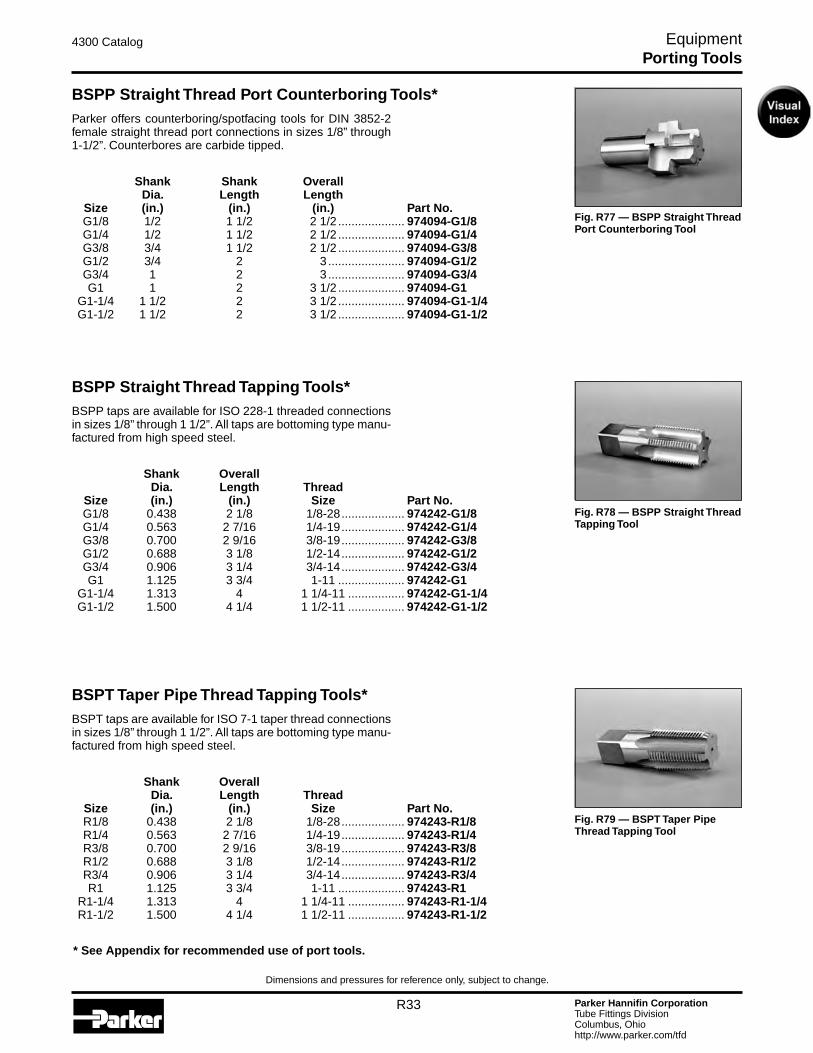
Parker Hannifin CorporationTube Fittings DivisionColumbus, Ohiohttp://www.parker.com/tfd
R33
4300 Catalog Equipment
Dimensions and pressures for reference only, subject to change.
BSPP Straight Thread Port Counterboring Tools*Parker offers counterboring/spotfacing tools for DIN 3852-2 female straight thread port connections in sizes 1/8” through 1-1/2”. Counterbores are carbide tipped.
Shank Shank Overall Dia. Length Length Size (in.) (in.) (in.) Part No. G1/8 1/2 1 1/2 2 1/2 .................... 974094-G1/8 G1/4 1/2 1 1/2 2 1/2 .................... 974094-G1/4 G3/8 3/4 1 1/2 2 1/2 .................... 974094-G3/8 G1/2 3/4 2 3 ....................... 974094-G1/2 G3/4 1 2 3 ....................... 974094-G3/4 G1 1 2 3 1/2 .................... 974094-G1 G1-1/4 1 1/2 2 3 1/2 .................... 974094-G1-1/4 G1-1/2 1 1/2 2 3 1/2 .................... 974094-G1-1/2
Fig. R77 — BSPP Straight Thread Port Counterboring Tool
Fig. R78 — BSPP Straight Thread Tapping Tool
BSPP Straight Thread Tapping Tools*BSPP taps are available for ISO 228-1 threaded connections in sizes 1/8” through 1 1/2”. All taps are bottoming type manu-factured from high speed steel.
Shank Overall Dia. Length Thread Size (in.) (in.) Size Part No. G1/8 0.438 2 1/8 1/8-28 ................... 974242-G1/8 G1/4 0.563 2 7/16 1/4-19 ................... 974242-G1/4 G3/8 0.700 2 9/16 3/8-19 ................... 974242-G3/8 G1/2 0.688 3 1/8 1/2-14 ................... 974242-G1/2 G3/4 0.906 3 1/4 3/4-14 ................... 974242-G3/4 G1 1.125 3 3/4 1-11 .................... 974242-G1 G1-1/4 1.313 4 1 1/4-11 ................. 974242-G1-1/4 G1-1/2 1.500 4 1/4 1 1/2-11 ................. 974242-G1-1/2
BSPT Taper Pipe Thread Tapping Tools*BSPT taps are available for ISO 7-1 taper thread connections in sizes 1/8” through 1 1/2”. All taps are bottoming type manu-factured from high speed steel.
Shank Overall Dia. Length Thread Size (in.) (in.) Size Part No. R1/8 0.438 2 1/8 1/8-28 ................... 974243-R1/8 R1/4 0.563 2 7/16 1/4-19 ................... 974243-R1/4 R3/8 0.700 2 9/16 3/8-19 ................... 974243-R3/8 R1/2 0.688 3 1/8 1/2-14 ................... 974243-R1/2 R3/4 0.906 3 1/4 3/4-14 ................... 974243-R3/4 R1 1.125 3 3/4 1-11 .................... 974243-R1 R1-1/4 1.313 4 1 1/4-11 ................. 974243-R1-1/4 R1-1/2 1.500 4 1/4 1 1/2-11 ................. 974243-R1-1/2
Fig. R79 — BSPT Taper Pipe Thread Tapping Tool
* See Appendix for recommended use of port tools.
Porting Tools
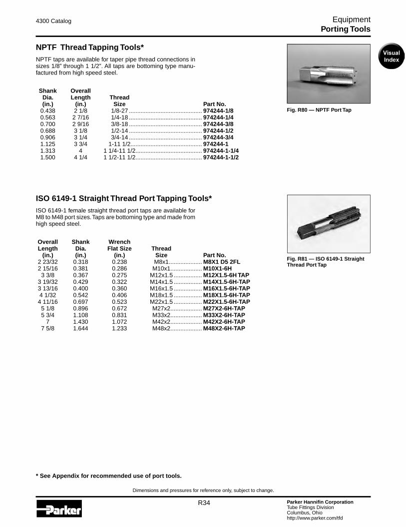
Parker Hannifin CorporationTube Fittings DivisionColumbus, Ohiohttp://www.parker.com/tfd
R34
4300 Catalog Equipment
Dimensions and pressures for reference only, subject to change.
Fig. R81 — ISO 6149-1 Straight Thread Port Tap
ISO 6149-1 Straight Thread Port Tapping Tools*ISO 6149-1 female straight thread port taps are available for M8 to M48 port sizes. Taps are bottoming type and made from high speed steel.
Overall Shank Wrench Length Dia. Flat Size Thread (in.) (in.) (in.) Size Part No. 2 23/32 0.318 0.238 M8x1 .................... M8X1 D5 2FL 2 15/16 0.381 0.286 M10x1 ................... M10X1-6H 3 3/8 0.367 0.275 M12x1.5 ................. M12X1.5-6H TAP 3 19/32 0.429 0.322 M14x1.5 ................. M14X1.5-6H-TAP 3 13/16 0.400 0.360 M16x1.5 ................. M16X1.5-6H-TAP 4 1/32 0.542 0.406 M18x1.5 ................. M18X1.5-6H-TAP 4 11/16 0.697 0.523 M22x1.5 ................. M22X1.5-6H-TAP 5 1/8 0.896 0.672 M27x2 ................... M27X2-6H-TAP 5 3/4 1.108 0.831 M33x2 ................... M33X2-6H-TAP 7 1.430 1.072 M42x2 ................... M42X2-6H-TAP 7 5/8 1.644 1.233 M48x2 ................... M48X2-6H-TAP
Fig. R80 — NPTF Port Tap
NPTF Thread Tapping Tools*NPTF taps are available for taper pipe thread connections in sizes 1/8” through 1 1/2”. All taps are bottoming type manu-factured from high speed steel.
Shank Overall Dia. Length Thread (in.) (in.) Size Part No. 0.438 2 1/8 1/8-27 ............................................ 974244-1/8 0.563 2 7/16 1/4-18 ............................................ 974244-1/4 0.700 2 9/16 3/8-18 ............................................ 974244-3/8 0.688 3 1/8 1/2-14 ............................................ 974244-1/2 0.906 3 1/4 3/4-14 ............................................ 974244-3/4 1.125 3 3/4 1-11 1/2 ........................................... 974244-1 1.313 4 1 1/4-11 1/2 ........................................ 974244-1-1/4 1.500 4 1/4 1 1/2-11 1/2 ........................................ 974244-1-1/2
* See Appendix for recommended use of port tools.
Porting Tools
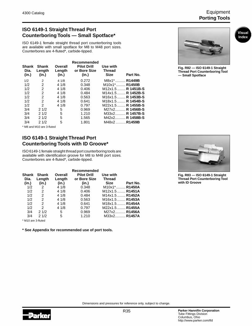
Parker Hannifin CorporationTube Fittings DivisionColumbus, Ohiohttp://www.parker.com/tfd
R35
4300 Catalog Equipment
Dimensions and pressures for reference only, subject to change.
Fig. R83 — ISO 6149-1 Straight Thread Port Counterboring Tool with ID Groove
ISO 6149-1 Straight Thread Port Counterboring Tools — Small Spotface*ISO 6149-1 female straight thread port counterboring tools are available with small spotface for M8 to M48 port sizes. Counterbores are 4-fluted*, carbide-tipped.
Recommended Shank Shank Overall Pilot Drill Use with Dia. Length Length or Bore Size Thread (in.) (in.) (in.) (in.) Size Part No.
1/2 2 4 1/8 0.272 M8x1* .......... R1449B 1/2 2 4 1/8 0.348 M10x1* ......... R1450B 1/2 2 4 1/8 0.406 M12x1.5 ........ R 1451B-S 1/2 2 4 1/8 0.484 M14x1.5 ........ R 1452B-S 1/2 2 4 1/8 0.563 M16x1.5 ........ R 1453B-S 1/2 2 4 1/8 0.641 M18x1.5 ........ R 1454B-S 1/2 2 4 1/8 0.797 M22x1.5 ........ R 1455B-S 3/4 2 1/2 5 0.969 M27x2 .......... R 1456B-S 3/4 2 1/2 5 1.210 M33x2 .......... R 1457B-S 3/4 2 1/2 5 1.565 M42x2 .......... R 1458B-S 3/4 2 1/2 5 1.801 M48x2 ...........R1459B* M8 and M10 are 3-fluted
ISO 6149-1 Straight Thread Port Counterboring Tools with ID Groove*ISO 6149-1 female straight thread port counterboring tools are available with identification groove for M8 to M48 port sizes. Counterbores are 4-fluted*, carbide-tipped.
Recommended Shank Shank Overall Pilot Drill Use with Dia. Length Length or Bore Size Thread (in.) (in.) (in.) (in.) Size Part No. 1/2 2 4 1/8 0.348 M10x1* ......... R1450A 1/2 2 4 1/8 0.406 M12x1.5 ........ R1451A 1/2 2 4 1/8 0.484 M14x1.5 ........ R1452A 1/2 2 4 1/8 0.563 M16x1.5 ........ R1453A 1/2 2 4 1/8 0.641 M18x1.5 ........ R1454A 1/2 2 4 1/8 0.797 M22x1.5 ........ R1455A 3/4 2 1/2 5 0.969 M27x2 .......... R1456A 3/4 2 1/2 5 1.210 M33x2 .......... R1457A* M10 are 3-fluted
* See Appendix for recommended use of port tools.
Porting Tools
Fig. R82 — ISO 6149-1 Straight Thread Port Counterboring Tool — Small Spotface
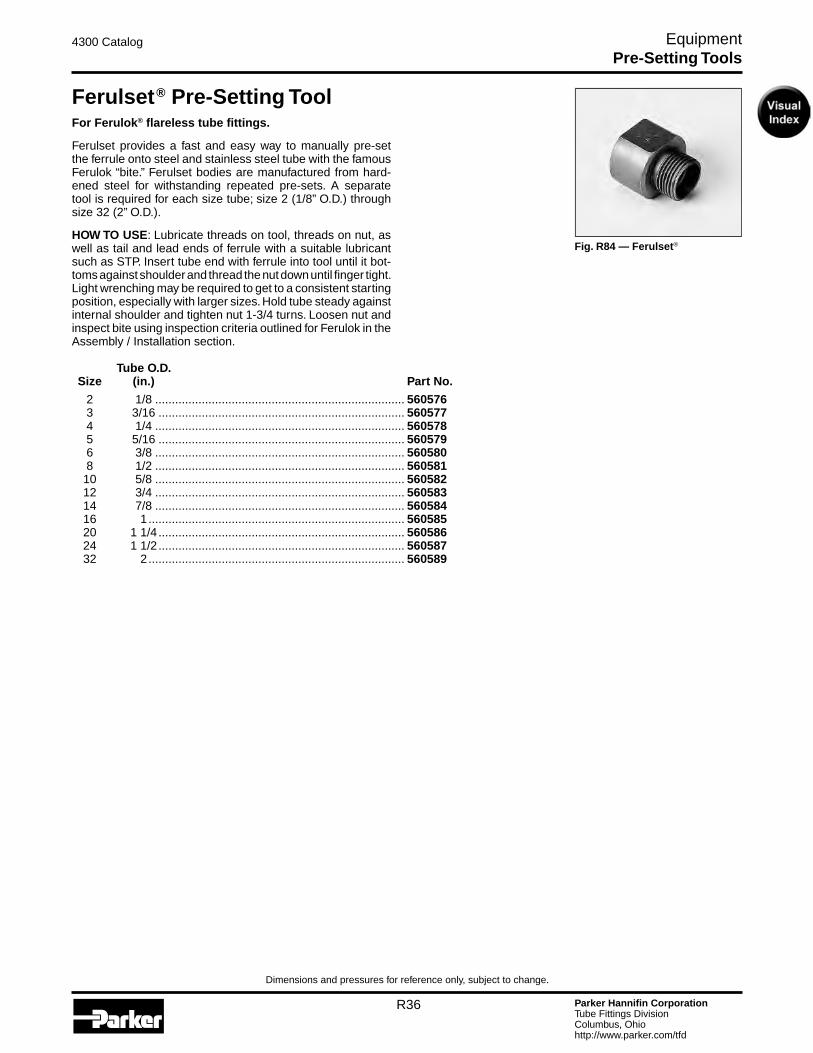
Parker Hannifin CorporationTube Fittings DivisionColumbus, Ohiohttp://www.parker.com/tfd
R36
4300 Catalog Equipment
Dimensions and pressures for reference only, subject to change.
Fig. R84 — Ferulset®
Ferulset® Pre-Setting ToolFor Ferulok® flareless tube fittings.
Ferulset provides a fast and easy way to manually pre-set the ferrule onto steel and stainless steel tube with the famous Ferulok “bite.” Ferulset bodies are manufactured from hard-ened steel for withstanding repeated pre-sets. A separate tool is required for each size tube; size 2 (1/8” O.D.) through size 32 (2” O.D.).
HOW TO USE: Lubricate threads on tool, threads on nut, as well as tail and lead ends of ferrule with a suitable lubricant such as STP. Insert tube end with ferrule into tool until it bot-toms against shoulder and thread the nut down until finger tight. Light wrenching may be required to get to a consistent starting position, especially with larger sizes. Hold tube steady against internal shoulder and tighten nut 1-3/4 turns. Loosen nut and inspect bite using inspection criteria outlined for Ferulok in the Assembly / Installation section. Tube O.D. Size (in.) Part No.
2 1/8 ........................................................................... 560576 3 3/16 .......................................................................... 560577 4 1/4 ........................................................................... 560578 5 5/16 .......................................................................... 560579 6 3/8 ........................................................................... 560580 8 1/2 ........................................................................... 560581 10 5/8 ........................................................................... 560582 12 3/4 ........................................................................... 560583 14 7/8 ........................................................................... 560584 16 1 ............................................................................. 560585 20 1 1/4 .......................................................................... 560586 24 1 1/2 .......................................................................... 560587 32 2 ............................................................................. 560589
Pre-Setting Tools

Parker Hannifin CorporationTube Fittings DivisionColumbus, Ohiohttp://www.parker.com/tfd
R37
4300 Catalog Equipment
Dimensions and pressures for reference only, subject to change.
Fig. R85 — VOMO Pre-Assembly Tool
VOMO Pre-Assembly BodiesFor EO and EO-2 Flareless Metric Tube Fittings
VOMO tools are made of hardened tool-steel, for standard assembly of steel fittings, stainless steel fittings and hose standpipes (BE).
Refer to the EO/EO2 Assembly and Installation section for use information (page S28).
NOTE: It is strongly recommended that a hydraulic tool be used to preset EO and EO-2 fittings in sizes 30S, 35L, 38S and 42L.
Tube O.D. Series (mm) Part No. LL 4 ............................................................................. VOMO04LLX LL 6 ............................................................................. VOMO06LLX LL 8 ............................................................................. VOMO08LLX LL 10 ............................................................................ VOMO10LLX LL 12 ............................................................................ VOMO12LLX L 6 ............................................................................. VOMO06LX L 8 ............................................................................. VOMO08LX L 10 ............................................................................ VOMO10LX L 12 ............................................................................ VOMO12LX L 15 ............................................................................ VOMO15LX L 18 ............................................................................ VOMO18LX L 22 ............................................................................ VOMO22LX L 28 ............................................................................ VOMO28LX L 35 ............................................................................ VOMO35LX L 42 ............................................................................ VOMO42LX S 6 ............................................................................. VOMO06SX S 8 ............................................................................. VOMO08SX S 10 ............................................................................ VOMO10SX S 12 ............................................................................ VOMO12SX S 14 ............................................................................ VOMO14SX S 16 ............................................................................ VOMO16SX S 20 ............................................................................ VOMO20SX S 25 ............................................................................ VOMO25SX S 30 ............................................................................ VOMO30SX S 38 ............................................................................ VOMO38SX
Pre-Setting Tools

Parker Hannifin CorporationTube Fittings DivisionColumbus, Ohiohttp://www.parker.com/tfd
R38
4300 Catalog Equipment
Dimensions and pressures for reference only, subject to change.
Fig. R86 — Hyferset
Fig. R87 — Electric Pump
Fig. R88 — Hand Pump
HyfersetParker Hydraulic Ferrule Pre-Setting Tool for Ferulok® Fittings and EO/EO-2 Metric Fittings
PORTABLE...EFFICIENT...EASY TO USE
The Hyferset is an efficient, dependable device for pre-setting Parker ferrules on tube of steel and stainless steel. This task is made easy through hydraulic power provided by a hand or electric pump. The equipment is portable, and has an optional sturdy wood carrying case.
In hydraulic pre-setting, little physical strength is required by the operator to set ferrules properly. Although the amount of force needed increases as the ferrule size increases, the pressure can be easily achieved.
This tool accommodates pre-setting dies for tubes ranging in size from 4 through 32 (1/4” through 2” outside diameter) and 6mm to 28mm O.D. metric sizes. The tube, with tube nut and ferrule, is positioned in the die. The hydraulic “push” of the Hyferset pre-sets the ferrule onto the tube — producing a visible ridge of metal, in front of the sleeve bite edge, that can be easily inspected.
Positive Stop Body Dies (For Ferulok Fittings Only)
The positive stop body die design eliminates the need for predetermined relief valve settings, pressure gauges or chart reading. Positive stop feature allows for uniform assemblies to be made on tube from 1/4” thru 2”. One set of dies can be used on both steel and stainless steel tube. When used in conjunction with the Ferulok visible bite ferrules, the entire system is the most reliable method available for assembling a fitting to a piece of tube.
See Appendix for pre-setting pressures for EO and EO-2 steel fittings.
You will find instructions for proper use in the 4393-B1 user manual.
COMPONENTS REQUIRED
Part Name Part No.*Hyferset (basic unit, no accessories) ........................................ 611011A*Hyferset Adapter ....................................................................... 6 FLO-SGauge “T” Adapter ...................................................................... 6 R6LO-S*Hose Assembly ......................................................................... 910004Gauge Swivel Adapter ................................................................ 6 G6L-SPressure Gauge (0 - 10,000 psi) ................................................ 900044*Hand pump (10,000 psi, 2 speed) ............................................. 900086Electric pump (10,000 psi, 1/2 HP, 40-125 volt) .......................... 900085Nut die set (1/4” to 2” O.D.) ......................................................... See page R39Positive Stop body die (1/4” to 2” O.D.) ....................................... See page R39Nut Die Set (6mm to 28mm) ....................................................... See page R40Body Die (6mm to 28mm) ........................................................... See page R40* Included in Hyferset Kit
Part Name Part No.Hyferset Kit ................................................................................. 611049C Includes basic unit, hand hydraulic pump, hose assembly, 1 adapter (6 FLO-S), wooden carrying case, operation manual and video.
Pre-Setting Tools
Fig. R89 — Hyferset Kit
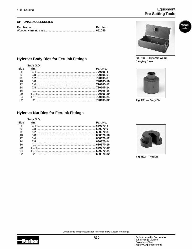
Parker Hannifin CorporationTube Fittings DivisionColumbus, Ohiohttp://www.parker.com/tfd
R39
4300 Catalog Equipment
Dimensions and pressures for reference only, subject to change.
Fig. R90 — Hyferset Wood Carrying Case
OPTIONAL ACCESSORIES
Part Name Part No.Wooden carrying case ................................................................ 651085
Hyferset Body Dies for Ferulok Fittings Tube O.D. Size (in.) Part No. 4 1/4 ........................................................................... 720105-4 6 3/8 ........................................................................... 720105-6 8 1/2 ........................................................................... 720105-8 10 5/8 ........................................................................... 720105-10 12 3/4 ........................................................................... 720105-12 14 7/8 ........................................................................... 720105-14 16 1 ............................................................................. 720105-16 20 1 1/4 .......................................................................... 720105-20 24 1 1/2 .......................................................................... 720105-24 32 2 ............................................................................. 720105-32
Hyferset Nut Dies for Ferulok Fittings Tube O.D. Size (in.) Part No. 4 1/4 ........................................................................... 680370-4 6 3/8 ........................................................................... 680370-6 8 1/2 ........................................................................... 680370-8 10 5/8 ........................................................................... 680370-10 12 3/4 ........................................................................... 680370-12 14 7/8 ........................................................................... 680370-14 16 1 ............................................................................. 680370-16 20 1 1/4 .......................................................................... 680370-20 24 1 1/2 .......................................................................... 680370-24 32 2 ............................................................................. 680370-32
Fig. R91 — Body Die
Fig. R92 — Nut Die
Pre-Setting Tools
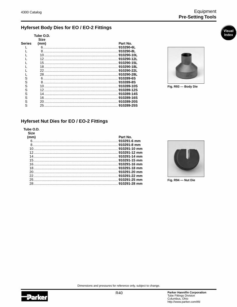
Parker Hannifin CorporationTube Fittings DivisionColumbus, Ohiohttp://www.parker.com/tfd
R40
4300 Catalog Equipment
Dimensions and pressures for reference only, subject to change.
Hyferset Body Dies for EO / EO-2 Fittings Tube O.D. Size Series (mm) Part No. L 6 ............................................................................. 910290-6L L 8 ............................................................................. 910290-8L L 10 ............................................................................ 910290-10L L 12 ............................................................................ 910290-12L L 15 ............................................................................ 910290-15L L 18 ............................................................................ 910290-18L L 22 ............................................................................ 910290-22L L 28 ............................................................................ 910290-28L S 6 ............................................................................. 910289-6S S 8 ............................................................................. 910289-8S S 10 ............................................................................ 910289-10S S 12 ............................................................................ 910289-12S S 14 ............................................................................ 910289-14S S 16 ............................................................................ 910289-16S S 20 ............................................................................ 910289-20S S 25 ............................................................................ 910289-25S
Hyferset Nut Dies for EO / EO-2 Fittings Tube O.D. Size (mm) Part No. 6 ........................................................................................ 910291-6 mm 8 ........................................................................................ 910291-8 mm 10 ....................................................................................... 910291-10 mm 12 ....................................................................................... 910291-12 mm 14 ....................................................................................... 910291-14 mm 15 ....................................................................................... 910291-15 mm 16 ....................................................................................... 910291-16 mm 18 ....................................................................................... 910291-18 mm 20 ....................................................................................... 910291-20 mm 22 ....................................................................................... 910291-22 mm 25 ....................................................................................... 910291-25 mm 28 ....................................................................................... 910291-28 mm
Fig. R93 — Body Die
Fig. R94 — Nut Die
Pre-Setting Tools
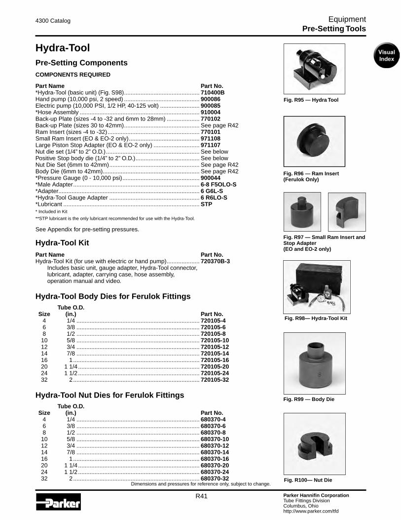
Parker Hannifin CorporationTube Fittings DivisionColumbus, Ohiohttp://www.parker.com/tfd
R41
4300 Catalog Equipment
Dimensions and pressures for reference only, subject to change.
Fig. R96 — Ram Insert (Ferulok Only)
Fig. R97 — Small Ram Insert and Stop Adapter (EO and EO-2 only)
Hydra-ToolPre-Setting ComponentsCOMPONENTS REQUIRED
Part Name Part No.*Hydra-Tool (basic unit) (Fig. S98) .............................................. 710400BHand pump (10,000 psi, 2 speed) .............................................. 900086Electric pump (10,000 PSI, 1/2 HP, 40-125 volt) ........................ 900085*Hose Assembly ......................................................................... 910004Back-up Plate (sizes -4 to -32 and 6mm to 28mm) .................... 770102Back-up Plate (sizes 30 to 42mm) .............................................. See page R42Ram Insert (sizes -4 to -32) ........................................................ 770101Small Ram Insert (EO & EO-2 only) ........................................... 971108Large Piston Stop Adapter (EO & EO-2 only) ............................ 971107Nut die set (1/4” to 2” O.D.) ......................................................... See belowPositive Stop body die (1/4” to 2” O.D.) ....................................... See belowNut Die Set (6mm to 42mm) ....................................................... See page R42Body Die (6mm to 42mm) ........................................................... See page R42*Pressure Gauge (0 - 10,000 psi) ............................................... 900044*Male Adapter ............................................................................. 6-8 F5OLO-S*Adapter ...................................................................................... 6 G6L-S*Hydra-Tool Gauge Adapter ....................................................... 6 R6LO-S*Lubricant ................................................................................... STP* Included in Kit
**STP lubricant is the only lubricant recommended for use with the Hydra-Tool.
See Appendix for pre-setting pressures.
Hydra-Tool KitPart Name Part No.Hydra-Tool Kit (for use with electric or hand pump) .................... 720370B-3 Includes basic unit, gauge adapter, Hydra-Tool connector, lubricant, adapter, carrying case, hose assembly, operation manual and video.
Hydra-Tool Body Dies for Ferulok Fittings Tube O.D. Size (in.) Part No. 4 1/4 ........................................................................... 720105-4 6 3/8 ........................................................................... 720105-6 8 1/2 ........................................................................... 720105-8 10 5/8 ........................................................................... 720105-10 12 3/4 ........................................................................... 720105-12 14 7/8 ........................................................................... 720105-14 16 1 ............................................................................. 720105-16 20 1 1/4 .......................................................................... 720105-20 24 1 1/2 .......................................................................... 720105-24 32 2 ............................................................................. 720105-32
Hydra-Tool Nut Dies for Ferulok Fittings Tube O.D. Size (in.) Part No. 4 1/4 ........................................................................... 680370-4 6 3/8 ........................................................................... 680370-6 8 1/2 ........................................................................... 680370-8 10 5/8 ........................................................................... 680370-10 12 3/4 ........................................................................... 680370-12 14 7/8 ........................................................................... 680370-14 16 1 ............................................................................. 680370-16 20 1 1/4 .......................................................................... 680370-20 24 1 1/2 .......................................................................... 680370-24 32 2 ............................................................................. 680370-32
Fig. R99 — Body Die
Fig. R100— Nut Die
Pre-Setting Tools
Fig. R95 — Hydra Tool
Fig. R98— Hydra-Tool Kit
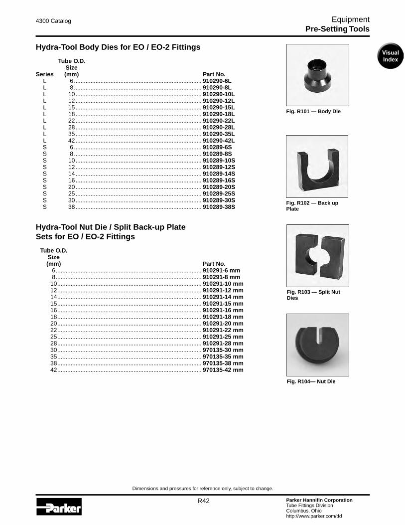
Parker Hannifin CorporationTube Fittings DivisionColumbus, Ohiohttp://www.parker.com/tfd
R42
4300 Catalog Equipment
Dimensions and pressures for reference only, subject to change.
Fig. R101 — Body Die
Fig. R104— Nut Die
Fig. R103 — Split Nut Dies
Hydra-Tool Body Dies for EO / EO-2 Fittings Tube O.D. Size Series (mm) Part No. L 6 ............................................................................. 910290-6L L 8 ............................................................................. 910290-8L L 10 ............................................................................ 910290-10L L 12 ............................................................................ 910290-12L L 15 ............................................................................ 910290-15L L 18 ............................................................................ 910290-18L L 22 ............................................................................ 910290-22L L 28 ............................................................................ 910290-28L L 35 ............................................................................ 910290-35L L 42 ............................................................................ 910290-42L S 6 ............................................................................. 910289-6S S 8 ............................................................................. 910289-8S S 10 ............................................................................ 910289-10S S 12 ............................................................................ 910289-12S S 14 ............................................................................ 910289-14S S 16 ............................................................................ 910289-16S S 20 ............................................................................ 910289-20S S 25 ............................................................................ 910289-25S S 30 ............................................................................ 910289-30S S 38 ............................................................................ 910289-38S
Hydra-Tool Nut Die / Split Back-up Plate Sets for EO / EO-2 Fittings Tube O.D. Size (mm) Part No. 6 ........................................................................................ 910291-6 mm 8 ........................................................................................ 910291-8 mm 10 ....................................................................................... 910291-10 mm 12 ....................................................................................... 910291-12 mm 14 ....................................................................................... 910291-14 mm 15 ....................................................................................... 910291-15 mm 16 ....................................................................................... 910291-16 mm 18 ....................................................................................... 910291-18 mm 20 ....................................................................................... 910291-20 mm 22 ....................................................................................... 910291-22 mm 25 ....................................................................................... 910291-25 mm 28 ....................................................................................... 910291-28 mm 30 ....................................................................................... 970135-30 mm 35 ....................................................................................... 970135-35 mm 38 ....................................................................................... 970135-38 mm 42 ....................................................................................... 970135-42 mm
Pre-Setting Tools
Fig. R102 — Back up Plate

Parker Hannifin CorporationTube Fittings DivisionColumbus, Ohiohttp://www.parker.com/tfd
R43
4300 Catalog Equipment
Dimensions and pressures for reference only, subject to change.
Fig. R105— EO-Karrymat
EO-KarrymatThe EO-Karrymat is a dependable device for safe and efficient bite-type pre-setting. It allows pre-assembly of all sizes of EO, EO-2 and Ferulok fittings without the need for electric power.
The EO-Karrymat consists of a hydraulic drive, Handpump and pressure gauge, all firmly attached to a carrying case.
Part Name Part No.EO-Karrymat .............................................................................. EOKarrymat
EO-Karrymat Body Dies for EO / EO-2 Fittings Tube O.D. Series (mm) Part No. LL 4 ............................................................................. MOK04LLX LL 6 ............................................................................. MOK06LLX LL 8 ............................................................................. MOK08LLX LL 10 ............................................................................ MOK10LLX LL 12 ............................................................................ MOK12LLX L 6 ............................................................................. MOK06LX L 8 ............................................................................. MOK08LX L 10 ............................................................................ MOK10LX L 12 ............................................................................ MOK12LX L 15 ............................................................................ MOK15LX L 18 ............................................................................ MOK18LX L 22 ............................................................................ MOK22LX L 28 ............................................................................ MOK28LX L 35 ............................................................................ MOK35LX L 42 ............................................................................ MOK42LX S 6 ............................................................................. MOK06SX S 8 ............................................................................. MOK08SX S 10 ............................................................................ MOK10SX S 12 ............................................................................ MOK12SX S 14 ............................................................................ MOK14SX S 16 ............................................................................ MOK16SX S 20 ............................................................................ MOK20SX S 25 ............................................................................ MOK25SX S 30 ............................................................................ MOK30SX
Fig. R106 — MOK Body Die
Pre-Setting Tools
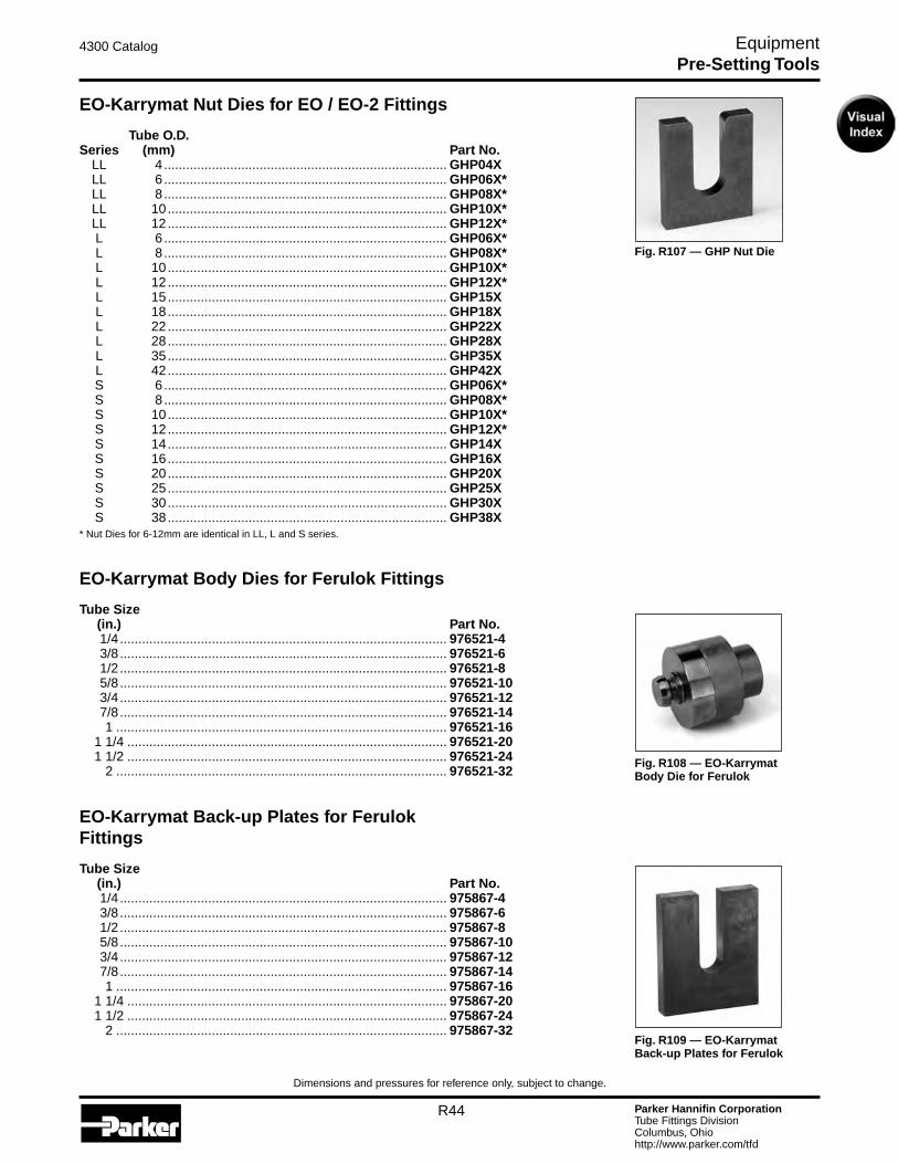
Parker Hannifin CorporationTube Fittings DivisionColumbus, Ohiohttp://www.parker.com/tfd
R44
4300 Catalog Equipment
Dimensions and pressures for reference only, subject to change.
Fig. R107 — GHP Nut Die
EO-Karrymat Nut Dies for EO / EO-2 Fittings Tube O.D. Series (mm) Part No. LL 4 ............................................................................. GHP04X LL 6 ............................................................................. GHP06X* LL 8 ............................................................................. GHP08X* LL 10 ............................................................................ GHP10X* LL 12 ............................................................................ GHP12X* L 6 ............................................................................. GHP06X* L 8 ............................................................................. GHP08X* L 10 ............................................................................ GHP10X* L 12 ............................................................................ GHP12X* L 15 ............................................................................ GHP15X L 18 ............................................................................ GHP18X L 22 ............................................................................ GHP22X L 28 ............................................................................ GHP28X L 35 ............................................................................ GHP35X L 42 ............................................................................ GHP42X S 6 ............................................................................. GHP06X* S 8 ............................................................................. GHP08X* S 10 ............................................................................ GHP10X* S 12 ............................................................................ GHP12X* S 14 ............................................................................ GHP14X S 16 ............................................................................ GHP16X S 20 ............................................................................ GHP20X S 25 ............................................................................ GHP25X S 30 ............................................................................ GHP30X S 38 ............................................................................ GHP38X* Nut Dies for 6-12mm are identical in LL, L and S series.
EO-Karrymat Body Dies for Ferulok Fittings Tube Size (in.) Part No. 1/4 ......................................................................................... 976521-4 3/8 ......................................................................................... 976521-6 1/2 ......................................................................................... 976521-8 5/8 ......................................................................................... 976521-10 3/4 ......................................................................................... 976521-12 7/8 ......................................................................................... 976521-14 1 .......................................................................................... 976521-16 1 1/4 ....................................................................................... 976521-20 1 1/2 ....................................................................................... 976521-24 2 .......................................................................................... 976521-32
EO-Karrymat Back-up Plates for Ferulok Fittings Tube Size (in.) Part No. 1/4 ......................................................................................... 975867-4 3/8 ......................................................................................... 975867-6 1/2 ......................................................................................... 975867-8 5/8 ......................................................................................... 975867-10 3/4 ......................................................................................... 975867-12 7/8 ......................................................................................... 975867-14 1 .......................................................................................... 975867-16 1 1/4 ....................................................................................... 975867-20 1 1/2 ....................................................................................... 975867-24 2 .......................................................................................... 975867-32
Fig. R108 — EO-Karrymat Body Die for Ferulok
Fig. R109 — EO-Karrymat Back-up Plates for Ferulok
Pre-Setting Tools
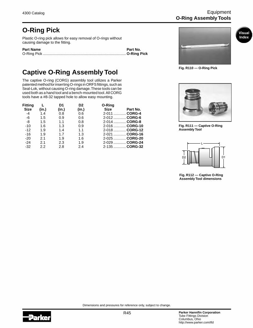
Parker Hannifin CorporationTube Fittings DivisionColumbus, Ohiohttp://www.parker.com/tfd
R45
4300 Catalog Equipment
Dimensions and pressures for reference only, subject to change.
O-Ring PickPlastic O-ring pick allows for easy removal of O-rings without causing damage to the fitting.
Part Name Part No.O-Ring Pick ................................................................................ O-Ring Pick
Captive O-Ring Assembly ToolThe captive O-ring (CORG) assembly tool utilizes a Parker patented method for inserting O-rings in ORFS fittings, such as Seal-Lok, without causing O-ring damage. These tools can be used both as a hand tool and a bench-mounted tool. All CORG tools have a #8-32 tapped hole to allow easy mounting.
Fitting L D1 D2 O-Ring Size (in.) (in.) (in.) Size Part No. -4 1.4 0.8 0.6 2-011 ............ CORG-4 -6 1.5 0.9 0.6 2-012 ............ CORG-6 -8 1.5 1.1 0.8 2-014 ............ CORG-8 -10 1.6 1.3 0.9 2-016 ............ CORG-10 -12 1.9 1.4 1.1 2-018 ............ CORG-12 -16 1.9 1.7 1.3 2-021 ............ CORG-16 -20 2.1 1.9 1.6 2-025 ............ CORG-20 -24 2.1 2.3 1.9 2-029 ............ CORG-24 -32 2.2 2.8 2.4 2-135 ............ CORG-32
Fig. R111 — Captive O-Ring Assembly Tool
Fig. R110 — O-Ring Pick
Fig. R112 — Captive O-Ring Assembly Tool dimensions
O-Ring Assembly Tools

Parker Hannifin CorporationTube Fittings DivisionColumbus, Ohiohttp://www.parker.com/tfd
R46
4300 Catalog Equipment
Dimensions and pressures for reference only, subject to change.
Fig. R113 — Braze Flux
Fig. R114 — Post Braze Cleaner
Braze FluxBlack braze flux can be used for brazing either steel or stainless steel components. When applied liberally this flux helps the flow of the silver braze alloy and prevents oxidation.
Part Name Part No.Black Flux ................................................................................... Black Flux 1/2 lbBlack Flux ................................................................................... Black Flux 1 lb
Post Braze CleanerThis cleaner is used to clean the assembly after brazing. Once the silver braze alloy has solidified, immediately immerse the joint into the braze cleaner solution. The cleaner combined with the sudden change in temperature removes the flux from the assembly. Braze cleaner does not provide corrosion protection. See “Corrosion Protection After Brazing” in the Assembly / Installation section, page S17.
Available in sizes 2 1/2 lb. and 5 lb. jars. When ordering simply denote quantity after Braze Cleaner.
Part Name Part No.Braze Cleaner ............................................................................. Braze Cleaner 2 1/2 lbBraze Cleaner ............................................................................. Braze Cleaner 5 lb
Braze Flux and Cleaner
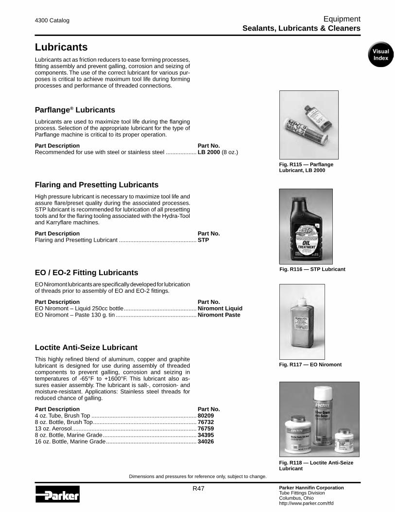
Parker Hannifin CorporationTube Fittings DivisionColumbus, Ohiohttp://www.parker.com/tfd
R47
4300 Catalog Equipment
Dimensions and pressures for reference only, subject to change.
Fig. R115 — Parflange Lubricant, LB 2000
Fig. R117 — EO Niromont
Fig. R118 — Loctite Anti-Seize Lubricant
Fig. R116 — STP Lubricant
LubricantsLubricants act as friction reducers to ease forming processes, fitting assembly and prevent galling, corrosion and seizing of components. The use of the correct lubricant for various pur-poses is critical to achieve maximum tool life during forming processes and performance of threaded connections.
Parflange® LubricantsLubricants are used to maximize tool life during the flanging process. Selection of the appropriate lubricant for the type of Parflange machine is critical to its proper operation.
Part Description Part No.Recommended for use with steel or stainless steel ................... LB 2000 (8 oz.)
Flaring and Presetting LubricantsHigh pressure lubricant is necessary to maximize tool life and assure flare/preset quality during the associated processes. STP lubricant is recommended for lubrication of all presetting tools and for the flaring tooling associated with the Hydra-Tool and Karryflare machines.
Part Description Part No.Flaring and Presetting Lubricant ................................................ STP
EO / EO-2 Fitting LubricantsEO Niromont lubricants are specifically developed for lubrication of threads prior to assembly of EO and EO-2 fittings.
Part Description Part No.EO Niromont – Liquid 250cc bottle ............................................. Niromont LiquidEO Niromont – Paste 130 g. tin .................................................. Niromont Paste
Loctite Anti-Seize LubricantThis highly refined blend of aluminum, copper and graphite lubricant is designed for use during assembly of threaded components to prevent galling, corrosion and seizing in temperatures of -65°F to +1600°F. This lubricant also as-sures easier assembly. The lubricant is salt-, corrosion- and moisture-resistant. Applications: Stainless steel threads for reduced chance of galling.
Part Description Part No.4 oz. Tube, Brush Top ................................................................. 802098 oz. Bottle, Brush Top ................................................................ 7673213 oz. Aerosol ............................................................................. 767598 oz. Bottle, Marine Grade .......................................................... 3439516 oz. Bottle, Marine Grade ........................................................ 34026
Sealants, Lubricants & Cleaners
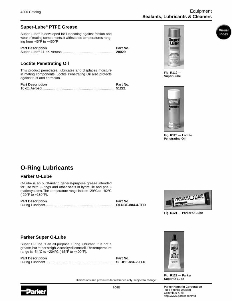
Parker Hannifin CorporationTube Fittings DivisionColumbus, Ohiohttp://www.parker.com/tfd
R48
4300 Catalog Equipment
Dimensions and pressures for reference only, subject to change.
Super-Lube® PTFE Grease Super-Lube® is developed for lubricating against friction and wear of mating components. It withstands temperatures rang-ing from -45°F to +450°F.
Part Description Part No.Super-Lube® 11 oz. Aerosol ....................................................... 20029
Loctite Penetrating OilThis product penetrates, lubricates and displaces moisture in mating components. Loctite Penetrating Oil also protects against rust and corrosion.
Part Description Part No.16 oz. Aerosol ............................................................................. 51221
Fig. R119 — Super-Lube
Fig. R120 — Loctite Penetrating Oil
Fig. R121 — Parker O-Lube
Fig. R122 — Parker Super O-Lube
O-Ring LubricantsParker O-LubeO-Lube is an outstanding general-purpose grease intended for use with O-rings and other seals in hydraulic and pneu-matic systems. The temperature range is from -29°C to +82°C (-20°F to +180°F).
Part Description Part No.O-ring Lubricant .......................................................................... OLUBE-884-4-TFD
Parker Super O-LubeSuper O-Lube is an all-purpose O-ring lubricant. It is not a grease, but rather a high-viscosity silicone oil. The temperature range is -54°C to +204°C (-65°F to +400°F).
Part Description Part No.O-ring Lubricant .......................................................................... SLUBE-884-2-TFD
Sealants, Lubricants & Cleaners
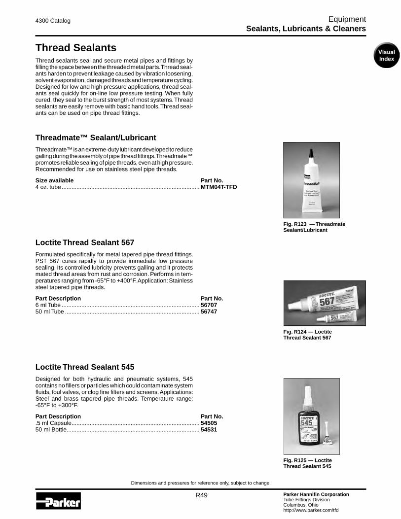
Parker Hannifin CorporationTube Fittings DivisionColumbus, Ohiohttp://www.parker.com/tfd
R49
4300 Catalog Equipment
Dimensions and pressures for reference only, subject to change.
Fig. R125 — Loctite Thread Sealant 545
Thread SealantsThread sealants seal and secure metal pipes and fittings by filling the space between the threaded metal parts. Thread seal-ants harden to prevent leakage caused by vibration loosening, solvent evaporation, damaged threads and temperature cycling. Designed for low and high pressure applications, thread seal-ants seal quickly for on-line low pressure testing. When fully cured, they seal to the burst strength of most systems. Thread sealants are easily remove with basic hand tools. Thread seal-ants can be used on pipe thread fittings.
Threadmate™ Sealant/LubricantThreadmate™ is an extreme-duty lubricant developed to reduce galling during the assembly of pipe thread fittings. Threadmate™ promotes reliable sealing of pipe threads, even at high pressure. Recommended for use on stainless steel pipe threads.
Size available Part No.4 oz. tube .................................................................................... MTM04T-TFD
Loctite Thread Sealant 567Formulated specifically for metal tapered pipe thread fittings. PST 567 cures rapidly to provide immediate low pressure sealing. Its controlled lubricity prevents galling and it protects mated thread areas from rust and corrosion. Performs in tem-peratures ranging from -65°F to +400°F. Application: Stainless steel tapered pipe threads.
Part Description Part No.6 ml Tube .................................................................................... 5670750 ml Tube .................................................................................. 56747
Loctite Thread Sealant 545Designed for both hydraulic and pneumatic systems, 545 contains no fillers or particles which could contaminate system fluids, foul valves, or clog fine filters and screens. Applications: Steel and brass tapered pipe threads. Temperature range: -65°F to +300°F.
Part Description Part No..5 ml Capsule .............................................................................. 5450550 ml Bottle ................................................................................. 54531
Fig. R123 — Threadmate Sealant/Lubricant
Fig. R124 — Loctite Thread Sealant 567
Sealants, Lubricants & Cleaners
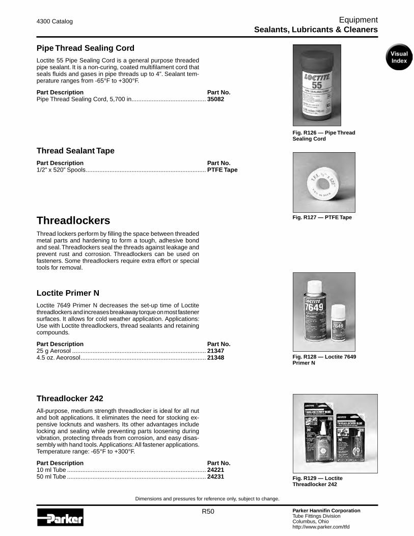
Parker Hannifin CorporationTube Fittings DivisionColumbus, Ohiohttp://www.parker.com/tfd
R50
4300 Catalog Equipment
Dimensions and pressures for reference only, subject to change.
Pipe Thread Sealing CordLoctite 55 Pipe Sealing Cord is a general purpose threaded pipe sealant. It is a non-curing, coated multifilament cord that seals fluids and gases in pipe threads up to 4”. Sealant tem-perature ranges from -65°F to +300°F.
Part Description Part No.Pipe Thread Sealing Cord, 5,700 in. ........................................... 35082
Thread Sealant TapePart Description Part No.1/2” x 520” Spools ....................................................................... PTFE Tape
ThreadlockersThread lockers perform by filling the space between threaded metal parts and hardening to form a tough, adhesive bond and seal. Threadlockers seal the threads against leakage and prevent rust and corrosion. Threadlockers can be used on fasteners. Some threadlockers require extra effort or special tools for removal.
Loctite Primer NLoctite 7649 Primer N decreases the set-up time of Loctite threadlockers and increases breakaway torque on most fastener surfaces. It allows for cold weather application. Applications: Use with Loctite threadlockers, thread sealants and retaining compounds.
Part Description Part No.25 g Aerosol ............................................................................... 213474.5 oz. Aeorosol .......................................................................... 21348
Threadlocker 242 All-purpose, medium strength threadlocker is ideal for all nut and bolt applications. It eliminates the need for stocking ex-pensive locknuts and washers. Its other advantages include locking and sealing while preventing parts loosening during vibration, protecting threads from corrosion, and easy disas-sembly with hand tools. Applications: All fastener applications. Temperature range: -65°F to +300°F.
Part Description Part No.10 ml Tube .................................................................................. 2422150 ml Tube .................................................................................. 24231
Fig. R128 — Loctite 7649 Primer N
Fig. R127 — PTFE Tape
Fig. R126 — Pipe Thread Sealing Cord
Fig. R129 — Loctite Threadlocker 242
Sealants, Lubricants & Cleaners

Parker Hannifin CorporationTube Fittings DivisionColumbus, Ohiohttp://www.parker.com/tfd
R51
4300 Catalog Equipment
Dimensions and pressures for reference only, subject to change.
Loctite High Strength Threadlocker 271High strength threadlocker for heavy-duty applications is es-pecially well-suited for permanently locking studs and press fits. It replaces set screw and snap rings and locks against vibration loosening. Applications: Permanent fastener require-ments. Temperature range: -65°F to +300°F. DO NOT USE THIS PRODUCT WITH PARKER TUBE FITTINGS. RECOM-MENDED ONLY FOR FASTENER APPLICATIONS.
Part Description Part No.10 ml Tube .................................................................................. 2712150 ml Tube .................................................................................. 27131
CleanersLoctite cleaners and degreasers are designed for various applications to remove grease, grime, paint, adhesives and other soils your working hands get into. Fast Orange hand cleaners have aded conditioners to prevent your hands from cracking and drying out.
Loctite Fast Orange Hand CleanerFast Orange is the #1 selling biodegradable, waterless pe-troleum solvent-free hand cleaner that contains no harsh chemicals, mineral oils or ammonia that can sting cuts and abrasions. Pure, fresh smelling natural citrus power does the cleaning. With aloe, lanolin, jojoba, and now Corn Huskers Lotion® for added skin conditioning and protection, its smooth formula gently deep cleans the toughest dirt. Applications: Clean-up of resins, oil, grease, tar, ink, epoxies, paint and various adhesives.
Part Description Part No.Industrial Hand Wipes, 75 count ................................................. 34943
Loctite Natural Blue® DegreaserThis biodegradable, all-purpose, industrial strength, concen-trated cleaner and degreaser can be easily diluted with water for use in a variety of cleaning applications. Non-flammable and non-toxic.
Part Description Part No.24 oz. Spray Bottle...................................................................... 822491 Gallon Concentrate .................................................................. 82251
Fig. R130 — Loctite High Strength Threadlocker 271
Fig. R131 — Loctite Fast Orange Hand Cleaner
Fig. R132 — Loctite Natural Blue® Degreaser
Sealants, Lubricants & Cleaners

Parker Hannifin CorporationTube Fittings DivisionColumbus, Ohiohttp://www.parker.com/tfd
R52
4300 Catalog Equipment
Dimensions and pressures for reference only, subject to change.
Loctite Pro Strength Parts Cleaner This product was developed to aggressively penetrate, dis-solve and remove oil and grease from parts. Dries quickly with no residue.
Part Description Part No.19 oz. Aerosol ............................................................................. 30548
Loctite RackParker’s Loctite Rack makes a convenient counter top display for Loctite products. No supplies included.
Part Description Part No.Loctite Product Rack .................................................................. RACK
Fig. R134 — Loctite Rack (Supplies not included)
Fig. R133 — Loctite Pro Strength Parts Cleaner
Sealants, Lubricants & Cleaners
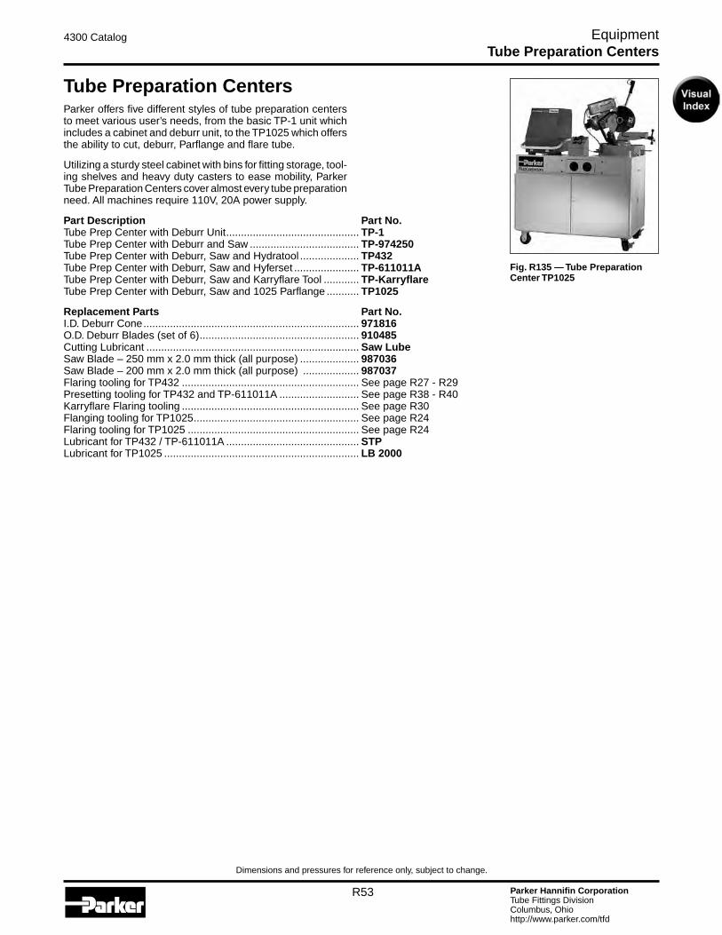
Parker Hannifin CorporationTube Fittings DivisionColumbus, Ohiohttp://www.parker.com/tfd
R53
4300 Catalog Equipment
Dimensions and pressures for reference only, subject to change.
Fig. R135 — Tube Preparation Center TP1025
Tube Preparation CentersParker offers five different styles of tube preparation centers to meet various user’s needs, from the basic TP-1 unit which includes a cabinet and deburr unit, to the TP1025 which offers the ability to cut, deburr, Parflange and flare tube.
Utilizing a sturdy steel cabinet with bins for fitting storage, tool-ing shelves and heavy duty casters to ease mobility, Parker Tube Preparation Centers cover almost every tube preparation need. All machines require 110V, 20A power supply.
Part Description Part No.Tube Prep Center with Deburr Unit ............................................. TP-1Tube Prep Center with Deburr and Saw ..................................... TP-974250Tube Prep Center with Deburr, Saw and Hydratool .................... TP432Tube Prep Center with Deburr, Saw and Hyferset ...................... TP-611011ATube Prep Center with Deburr, Saw and Karryflare Tool ............ TP-KarryflareTube Prep Center with Deburr, Saw and 1025 Parflange ........... TP1025
Replacement Parts Part No.I.D. Deburr Cone ......................................................................... 971816O.D. Deburr Blades (set of 6) ...................................................... 910485Cutting Lubricant ........................................................................ Saw Lube Saw Blade – 250 mm x 2.0 mm thick (all purpose) .................... 987036Saw Blade – 200 mm x 2.0 mm thick (all purpose) ................... 987037Flaring tooling for TP432 ............................................................ See page R27 - R29Presetting tooling for TP432 and TP-611011A ........................... See page R38 - R40Karryflare Flaring tooling ............................................................ See page R30Flanging tooling for TP1025 ........................................................ See page R24Flaring tooling for TP1025 .......................................................... See page R24Lubricant for TP432 / TP-611011A ............................................. STPLubricant for TP1025 .................................................................. LB 2000
Tube Preparation Centers

Parker Hannifin CorporationTube Fittings DivisionColumbus, Ohiohttp://www.parker.com/tfd
R54
4300 Catalog Equipment
Dimensions and pressures for reference only, subject to change.
Fig. R136 — Thread Identification Kit
Thread Identification KitThe Thread Identification Kit can be used to identify metric, BSP, SAE and NPT threads, as well as SAE flanges. It con-tains thread gauges, calipers, thread profiles, and an instruction booklet that details most thread forms and connection styles found in fluidpower systems worldwide.
Part Name Part No.Thread Identification Kit .............................................................. MIK-1
PortboardsThe Portboards can be used for identification of ISO, SAE, BSP and NPT ports and port threads. They are machined with female threads for quick and easy identification by screwing in the male port end.
Portboard A (SAE Straight Thread -2 through -32 and NPT 1/8 through 1 1/2).
Part Name Part No.Portboard A ................................................................................ Portboard A
Portboard B (Metric 8mm through 48mm and BSP 1/8 through 1 1/2).
Part Name Part No.Portboard B ................................................................................ Portboard B
Fig. R137 — Portboard A
Fig. R138 — Portboard B
Fig. R139 — International Thread Kit (ITK)
International Thread KitParker’s International Thread Kit offers the necessary tools to identify almost any thread you may encounter. The new ITK has LL, L and S series plugs to identify female DIN threads such as EO style hose ends. It also includes the MIK-1 and BSPP plugs in order to identify BSPP hose ends from 1/8” to 2”.
Part Name Part No.International Thread Kit .............................................................. ITK
Thread Idnetification

Parker Hannifin CorporationTube Fittings DivisionColumbus, Ohiohttp://www.parker.com/tfd
R55
4300 Catalog Equipment
Dimensions and pressures for reference only, subject to change.
Inch Hex Size Par-Lok Wrenches
Hex Max. Size Torque (in.) (ft.-lbs.) Part No.
3/8 24 ............................................................................ 860062-6 7/16 27 ............................................................................ 860062-7 1/2 32 ............................................................................ 860062-8 9/16 43 ............................................................................ 860062-9 5/8 65 ............................................................................ 860062-10 11/16 81 ............................................................................ 860062-11 3/4 92 ............................................................................ 860062-12 13/16 108 ........................................................................... 860062-13 7/8 135 ........................................................................... 860062-14 15/16 152 ........................................................................... 860062-15 1 162 ........................................................................... 860062-16 1 1/8 206 ........................................................................... 860062-18 1 1/4 238 ........................................................................... 860062-20 1 3/8 282 ........................................................................... 860062-22 1 1/2 314 ........................................................................... 860062-24 1 5/8 346 ........................................................................... 860062-26 1 7/8 364 ........................................................................... 860062-30 2 373 ........................................................................... 860062-32 2 1/4 391 ........................................................................... 860062-36
Part Description Part No.Full kit of sizes 3/8” to 1” ............................................................. 860062-KITFull kit of sizes 1 1/8” to 2 1/4” .................................................... 860062-KIT2Seal-Lok Wrench Kit (5/8”, 11/16”, 3/4”, 13/16”, 7/8”, 15/16”) ............................... 860062-LKITTriple-Lok and Ferulok Wrench Kit (9/16”, 11/16”, 7/8”, 1”, 1 1/4”) ............................................. 860062-XUKIT
Fig. R142 — Par-Lok Wrench
Fig. R143 — Seal-Lok Wrench Kit
Fig. R140 — Par-Lok Wrench
Fig. R141 — Par-Lok Wrench Kit
Par-Lok® Wrench360° Snap-action ratchet wrench for hex sizes from 3/8” to 2 1/4” across the flats and metric from 10mm to 50mm. Inch sizes meet government specifications and are listed as NSN-5120-00-474-7227. Wrenches are covered by a limited lifetime warranty. Damage due to over-torque is not covered by warranty.
Install Tube Fittings FasterEasy access ratchet wrench speeds fittings installation in tight locations. Rugged, snap-action jaws can be opened over tube lines, locked onto fitting hex and ratcheted within 1/8 turn. Full six point contact prevents fitting distortion common with wrench slippage. Ideal for tube line installations where compact runs require multiple fittings make-up, disassembly and remakes.
SpecificationsPar-Lok wrenches are available individually or in six different kit combinations. Par-Lok jaws are constructed from drop-forged, high carbon steel material with a black conversion coat finish. Par-Lok handles are made from heavy gauge steel material, heat treated and with a corrosion resistant black finish. Solid stainless steel rivets and tempered jaw springs are designed into every wrench for maximum strength.
Wrenches
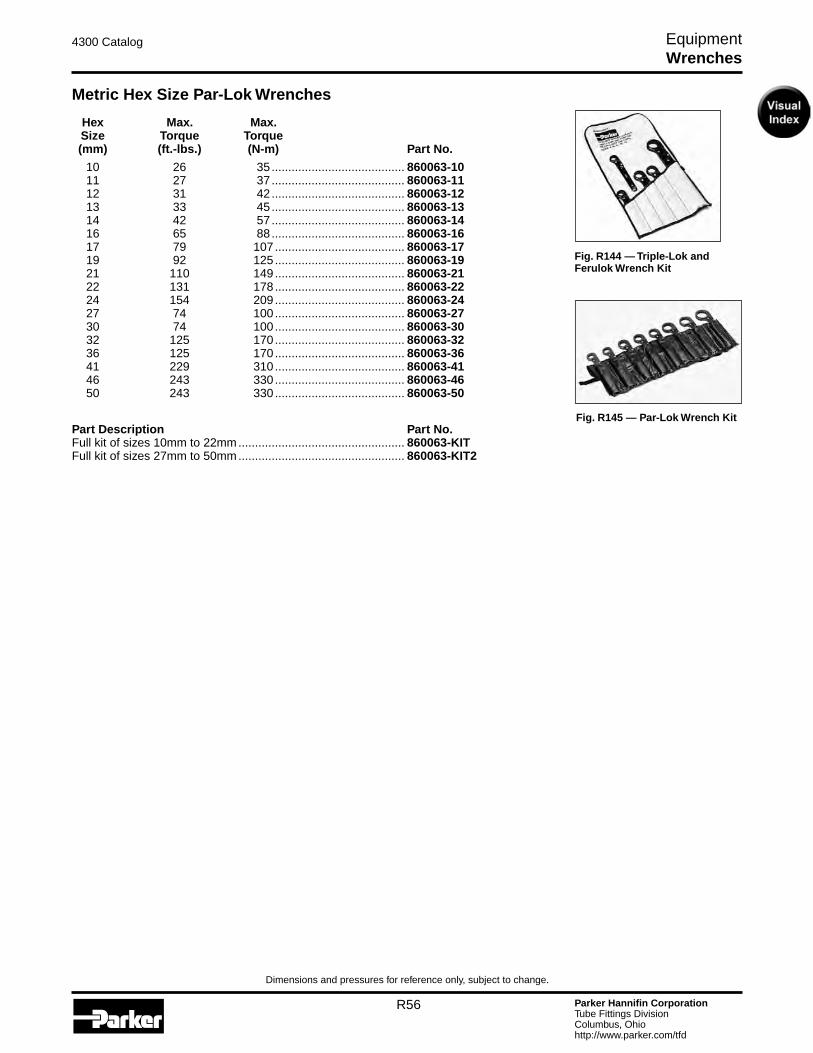
Parker Hannifin CorporationTube Fittings DivisionColumbus, Ohiohttp://www.parker.com/tfd
R56
4300 Catalog Equipment
Dimensions and pressures for reference only, subject to change.
Fig. R145 — Par-Lok Wrench Kit
Metric Hex Size Par-Lok Wrenches
Hex Max. Max. Size Torque Torque (mm) (ft.-lbs.) (N-m) Part No.
10 26 35 ........................................ 860063-10 11 27 37 ........................................ 860063-11 12 31 42 ........................................ 860063-12 13 33 45 ........................................ 860063-13 14 42 57 ........................................ 860063-14 16 65 88 ........................................ 860063-16 17 79 107 ....................................... 860063-17 19 92 125 ....................................... 860063-19 21 110 149 ....................................... 860063-21 22 131 178 ....................................... 860063-22 24 154 209 ....................................... 860063-24 27 74 100 ....................................... 860063-27 30 74 100 ....................................... 860063-30 32 125 170 ....................................... 860063-32 36 125 170 ....................................... 860063-36 41 229 310 ....................................... 860063-41 46 243 330 ....................................... 860063-46 50 243 330 ....................................... 860063-50
Part Description Part No.Full kit of sizes 10mm to 22mm .................................................. 860063-KITFull kit of sizes 27mm to 50mm .................................................. 860063-KIT2
Fig. R144 — Triple-Lok and Ferulok Wrench Kit
Wrenches
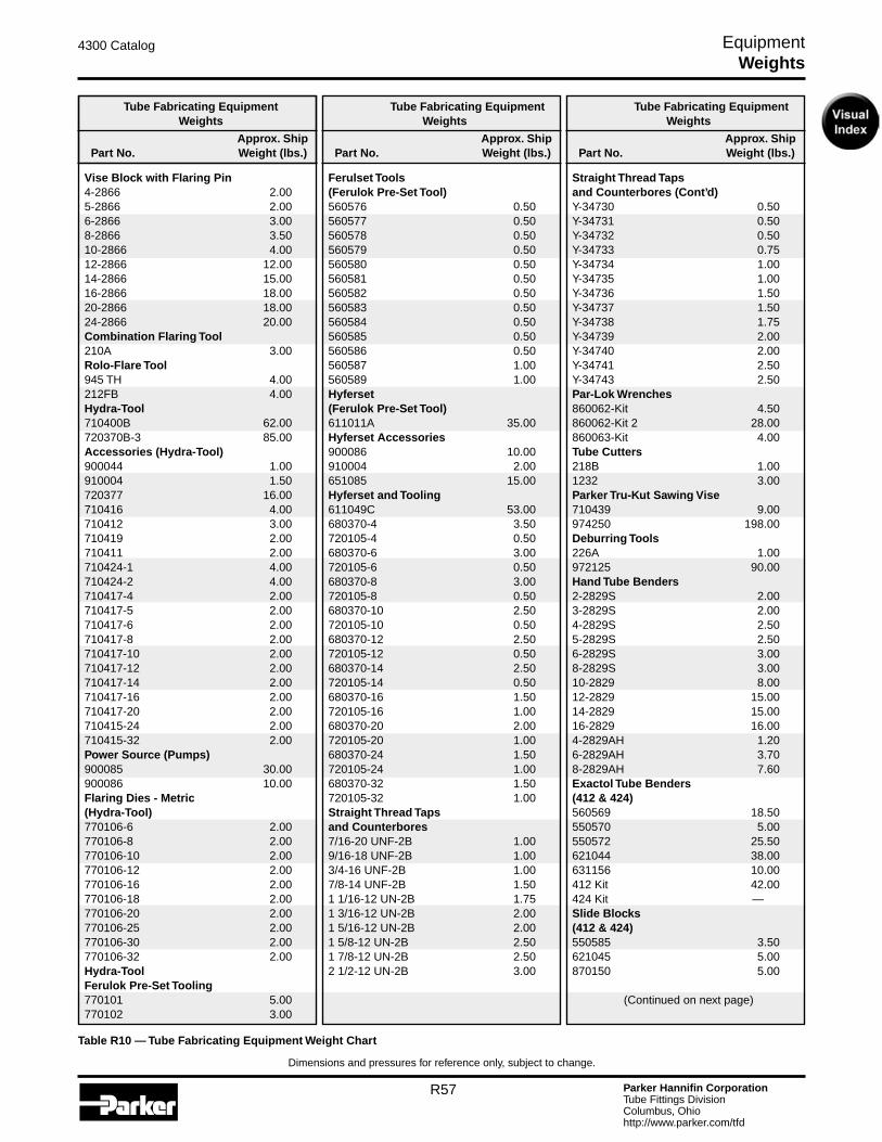
Parker Hannifin CorporationTube Fittings DivisionColumbus, Ohiohttp://www.parker.com/tfd
R57
4300 Catalog Equipment
Dimensions and pressures for reference only, subject to change.
Tube Fabricating Equipment Weights
Approx. Ship Part No. Weight (lbs.)
Straight Thread Taps and Counterbores (Cont’d)Y-34730 0.50Y-34731 0.50Y-34732 0.50Y-34733 0.75Y-34734 1.00Y-34735 1.00Y-34736 1.50Y-34737 1.50Y-34738 1.75Y-34739 2.00Y-34740 2.00Y-34741 2.50Y-34743 2.50Par-Lok Wrenches860062-Kit 4.50860062-Kit 2 28.00860063-Kit 4.00Tube Cutters218B 1.001232 3.00Parker Tru-Kut Sawing Vise710439 9.00974250 198.00Deburring Tools226A 1.00972125 90.00Hand Tube Benders2-2829S 2.003-2829S 2.004-2829S 2.505-2829S 2.506-2829S 3.008-2829S 3.0010-2829 8.0012-2829 15.0014-2829 15.0016-2829 16.004-2829AH 1.206-2829AH 3.708-2829AH 7.60Exactol Tube Benders (412 & 424)560569 18.50550570 5.00550572 25.50621044 38.00631156 10.00412 Kit 42.00424 Kit —Slide Blocks (412 & 424)550585 3.50621045 5.00870150 5.00
(Continued on next page)
Tube Fabricating Equipment Weights
Approx. Ship Part No. Weight (lbs.)
Ferulset Tools (Ferulok Pre-Set Tool)560576 0.50560577 0.50560578 0.50560579 0.50560580 0.50560581 0.50560582 0.50560583 0.50560584 0.50560585 0.50560586 0.50560587 1.00560589 1.00Hyferset (Ferulok Pre-Set Tool)611011A 35.00Hyferset Accessories900086 10.00910004 2.00651085 15.00Hyferset and Tooling611049C 53.00680370-4 3.50720105-4 0.50680370-6 3.00720105-6 0.50680370-8 3.00720105-8 0.50680370-10 2.50720105-10 0.50680370-12 2.50720105-12 0.50680370-14 2.50720105-14 0.50680370-16 1.50720105-16 1.00680370-20 2.00720105-20 1.00680370-24 1.50720105-24 1.00680370-32 1.50720105-32 1.00Straight Thread Taps and Counterbores7/16-20 UNF-2B 1.009/16-18 UNF-2B 1.003/4-16 UNF-2B 1.007/8-14 UNF-2B 1.501 1/16-12 UN-2B 1.751 3/16-12 UN-2B 2.001 5/16-12 UN-2B 2.001 5/8-12 UN-2B 2.501 7/8-12 UN-2B 2.502 1/2-12 UN-2B 3.00
Table R10 — Tube Fabricating Equipment Weight Chart
Tube Fabricating Equipment Weights
Approx. Ship Part No. Weight (lbs.)
Vise Block with Flaring Pin4-2866 2.005-2866 2.006-2866 3.008-2866 3.5010-2866 4.0012-2866 12.0014-2866 15.0016-2866 18.0020-2866 18.0024-2866 20.00Combination Flaring Tool210A 3.00Rolo-Flare Tool945 TH 4.00212FB 4.00Hydra-Tool710400B 62.00720370B-3 85.00Accessories (Hydra-Tool)900044 1.00910004 1.50720377 16.00710416 4.00710412 3.00710419 2.00710411 2.00710424-1 4.00710424-2 4.00710417-4 2.00710417-5 2.00710417-6 2.00710417-8 2.00710417-10 2.00710417-12 2.00710417-14 2.00710417-16 2.00710417-20 2.00710415-24 2.00710415-32 2.00Power Source (Pumps)900085 30.00900086 10.00Flaring Dies - Metric (Hydra-Tool)770106-6 2.00770106-8 2.00770106-10 2.00770106-12 2.00770106-16 2.00770106-18 2.00770106-20 2.00770106-25 2.00770106-30 2.00770106-32 2.00Hydra-Tool Ferulok Pre-Set Tooling770101 5.00770102 3.00
Weights
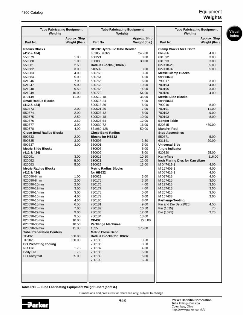
Parker Hannifin CorporationTube Fittings DivisionColumbus, Ohiohttp://www.parker.com/tfd
R58
4300 Catalog Equipment
Dimensions and pressures for reference only, subject to change.
Table R10 — Tube Fabricating Equipment Weight Chart (cont’d.)
Tube Fabricating Equipment Weights
Approx. Ship Part No. Weight (lbs.)
Radius Blocks (412 & 424)550579 1.00550580 1.00550581 2.50550582 3.00550583 4.00550584 5.00621046 7.00621047 9.00621048 9.50621049 10.00870149 11.00Small Radius Blocks (412 & 424)550573 2.00550574 2.00550575 2.50550576 2.50550577 3.00550578 4.00Close Bend Radius Blocks590533 2.00590535 3.00590537 3.00Metric Slide Blocks (412 & 424)820091 3.00820092 5.00820093 5.00Metric Radius Blocks (412 & 424)820090-6mm 1.00820090-8mm 2.00820090-10mm 2.00820090-12mm 3.00820090-14mm 3.00820090-15mm 4.00820090-16mm 4.50820090-18mm 6.50820090-20mm 7.00820090-22mm 9.00820090-25mm 9.50820090-28mm 10.00820090-30mm 10.50820090-32mm 11.00Tube Preparation CentersTP432 560.00TP1025 880.00EO Presetting ToolingNut Die 1.75Body Die .75EO-Karrymat 55.00
Tube Fabricating Equipment Weights
Approx. Ship Part No. Weight (lbs.)
HB632 Hydraulic Tube Bender631050 (632) 245.00660221 8.00900085 30.00Radius Blocks (HB632)540502 3.00530763 3.50530764 4.00530765 6.00530766 10.00530768 14.00530770 54.00590512-18 35.00590515-24 4.00590518-30 6.00590521-36 7.00590523-42 8.00590524-48 10.00590526-54 12.00590630-72 16.00631060-128 50.00Close Bend Radius Blocks for HB632530597 3.50530601 5.00530605 6.00530609 8.00530613 10.50530621 12.00530625 13.00Metric Radius Blocks for HB632810023 3.00780175 3.50780176 4.00780177 4.00780178 5.00780179 6.00780180 8.00780181 9.00780182 10.50780183 12.00780184 13.00CP432 225.00Parflange Machines1025 175.00Metric Close Bend Radius Blocks for HB632780185 3.50780186 3.50780187 4.00780188 5.00780189 6.00780190 6.50
Tube Fabricating Equipment Weights
Approx. Ship Part No. Weight (lbs.)
Clamp Blocks for HB632864266 4.00631092 3.00631093 3.00027418-28 5.00027418-32 5.00Metric Clamp Blocks for HB632790017 3.00780194 4.00780195 3.00780186 4.00Metric Slide Blocks for HB632790016 8.00780191 11.00780192 9.00780193 8.00Bender Table520515 470.00Mandrel Rod Stop Assemblies550571 5.00631141 20.00Universal Side Angle Indicator520520 25.00Karryflare 116.00Inch Flaring Dies for KarryflareM 047415-1 4.00M 157408-1 4.00M 067415-1 4.00M 087415 4.00M 107415 3.50M 127415 3.50M 167415 3.50M 207415 3.00M 157438 3.00Parflange ToolingPin and Die Set (1025) 4.50Pin (1025) .75Die (1025) 3.75
Weights