Equipment Guide - Dock Ladders, Dock Bumpers, Boat Ladders
16
Equipment Guide Boat Hoist Gear Plate Assembly Electric Motor Wiring Diagrams Drum Switch GFCI Boat Hoist USA assumes no responsibility or liability for installations and/or improper use of the equipment. This guide is intended to be used as a reference and a general guideline only. Boat Hoist USA is not responsible for the design, construction or installation of docks, piers or lifts. This guide is intended to be given to the end user of the equipment. Professional installers, please leave this guide with your customer!
Transcript of Equipment Guide - Dock Ladders, Dock Bumpers, Boat Ladders
Equipment Guide
Boat Hoist
Gear Plate Assembly
Electric Motor
Wiring Diagrams
Drum Switch
GFCI
Boat Hoist USA assumes no responsibility or liability for installations and/or improper use of the equipment. This guide is intended to be used as a reference and a general guideline only.
Boat Hoist USA is not responsible for the design, construction or installation of docks, piers or lifts.
This guide is intended to be given to the end user of the equipment. Professional installers, please leave this guide with your customer!
If you did not receive all your boxes or concerned about a shipment contact the Boat Hoist USA shipping department:
800-259-8715 Ext. 211
Table Of Contents
Page Section 2 About the Flat-Plate Boat Hoist
2 Mounting the Flat-Plate Hoist
3 Installing & Maintaining the Flat-Plate Hoist
4 Electric Motors
5 Wiring Diagrams for Electric Motors
8 Minimum Wire Size for Electric Motors
9 Drum Switches
10 Wiring Diagrams for Drum Switches
11 GFCI
12 Troubleshooting Guide
14 Warranty Information
Before Signing Delivery Ticket
Signing the delivery ticket as received is a contractual agreement for transfer of ownership from Boat Hoist USA to the signee. BEFORE you sign the delivery ticket make sure delivery is complete and no visible damages are present. If items are missing or shipment is damaged either notate this on the delivery ticket and have the driver sign this notation or refuse the shipment. If the shipment is delivered and signed as a complete delivery then it is understood by Boat Hoist USA that the shipment arrived complete with no damage.
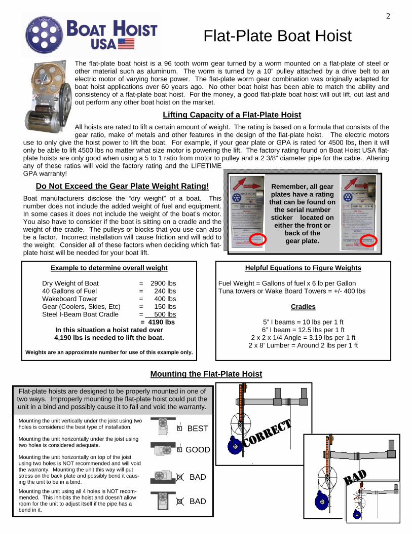
Flat-Plate Boat Hoist The flat-plate boat hoist is a 96 tooth worm gear turned by a worm mounted on a flat-plate of steel or other material such as aluminum. The worm is turned by a 10” pulley attached by a drive belt to an electric motor of varying horse power. The flat-plate worm gear combination was originally adapted for boat hoist applications over 60 years ago. No other boat hoist has been able to match the ability and consistency of a flat-plate boat hoist. For the money, a good flat-plate boat hoist will out lift, out last and out perform any other boat hoist on the market.
Lifting Capacity of a Flat-Plate Hoist
All hoists are rated to lift a certain amount of weight. The rating is based on a formula that consists of the gear ratio, make of metals and other features in the design of the flat-plate hoist. The electric motors
use to only give the hoist power to lift the boat. For example, if your gear plate or GPA is rated for 4500 lbs, then it will only be able to lift 4500 lbs no matter what size motor is powering the lift. The factory rating found on Boat Hoist USA flat-plate hoists are only good when using a 5 to 1 ratio from motor to pulley and a 2 3/8” diameter pipe for the cable. Altering any of these ratios will void the factory rating and the LIFETIME GPA warranty!
Do Not Exceed the Gear Plate Weight Rating!
Boat manufacturers disclose the “dry weight” of a boat. This number does not include the added weight of fuel and equipment. In some cases it does not include the weight of the boat’s motor. You also have to consider if the boat is sitting on a cradle and the weight of the cradle. The pulleys or blocks that you use can also be a factor. Incorrect installation will cause friction and will add to the weight. Consider all of these factors when deciding which flat-plate hoist will be needed for your boat lift.
Remember, all gear plates have a rating that can be found on
the serial number sticker located on either the front or
back of the gear plate.
Mounting the Flat-Plate Hoist
Flat-plate hoists are designed to be properly mounted in one of two ways. Improperly mounting the flat-plate hoist could put the unit in a bind and possibly cause it to fail and void the warranty.
Mounting the unit horizontally under the joist using two holes is considered adequate.
Mounting the unit vertically under the joist using two holes is considered the best type of installation.
Mounting the unit horizontally on top of the joist using two holes is NOT recommended and will void the warranty. Mounting the unit this way will put stress on the back plate and possibly bend it caus-ing the unit to be in a bind.
Mounting the unit using all 4 holes is NOT recom-mended. This inhibits the hoist and doesn’t allow room for the unit to adjust itself if the pipe has a bend in it.
GOOD √
BAD
BAD
BEST √
Helpful Equations to Figure Weights Fuel Weight = Gallons of fuel x 6 lb per Gallon Tuna towers or Wake Board Towers = +/- 400 lbs
Cradles
5” I beams = 10 lbs per 1 ft 6” I beam = 12.5 lbs per 1 ft
2 x 2 x 1/4 Angle = 3.19 lbs per 1 ft 2 x 8’ Lumber = Around 2 lbs per 1 ft
Example to determine overall weight
Dry Weight of Boat = 2900 lbs 40 Gallons of Fuel = 240 lbs Wakeboard Tower = 400 lbs Gear (Coolers, Skies, Etc) = 150 lbs Steel I-Beam Boat Cradle = 500 lbs = 4190 lbs
In this situation a hoist rated over 4,190 lbs is needed to lift the boat.
Weights are an approximate number for use of this example only.
CORRECT
BAD
2
A Flat-Plate Hoist is NOT a Load Bearing Unit One of the most important things to understand is that a flat-plate hoist is not a load bearing unit. If lifting the boat directly off the pipe, the installer must adequately support the pipe. We recommend some type of support every 10-12 feet, and always put a support between the unit and where the cable winds on the pipe. If the pipe is not supported correctly and the weight of the boat bends the pipe, the gear could ultimately break due to the leverage created. Signs that your hoist is in a bind or being used as Load Bearing: • Unit is not lifting the boat • Unit is making noise or “squealing” • Gear or back plate bearing breaks • You notice metal shavings coming out of the worm housing • Unit freezes or “locks up” and you cannot turn it by hand
Installing and Maintaining the Boat Hoist USA Flat-Plate Hoist • Unit may be mounted vertically or horizontally and must be straight. • Hang the Gear Plate Assembly (GPA) first before you bolt the motor to it. This will make installation considerably easer
as the completed hoist with the motor weighs well over 100 lbs. • Make sure the unit is not in a bind, bent or twisted in any manner. • All Boat Hoist USA hoists are rated based on using a 2” schedule 40 pipe. Changing the diameter of the pipe in any
way will change the unit rating. • Unit needs to be at a right angle to the pipe. If they are not aligned at a right angle, rapid wearing of gears will occur. • Unit must be properly greased. Boat Hoist USA recommends that you grease the unit a minimum of two times a year or
more depending on use. • Do not operate the unit more than two lifting cycles without giving it time to cool. • NEVER attempt to weld a unit or gear plate to the structure. Welding the unit will void the warranty. • Always use the bolt holes provided and bolt the unit using two of the four holes.
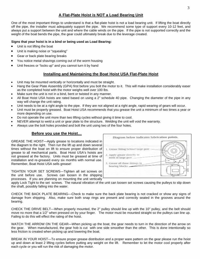
Before you use the Hoist… GREASE THE HOIST—Apply grease to locations indicated in the diagram to the right. Then run the lift up and down several times without the boat on lift to ensure proper distribution of grease to all mechanical parts. Boat Hoist USA’s hoists are not greased at the factory. Units must be greased at time of installation and re-greased every six months with normal use. Remember, Boat Hoist USA sells grease! TIGHTEN YOUR SET SCREWS—Tighten all set screws on the unit before use. Screws can loosen in the shipping processes. If you are planning on mounting the unit vertically apply Lock Tight to the set screws. The natural vibration of the unit can loosen set screws causing the pulleys to slip down the shaft, possibly falling into the water. CHECK THE BACK PLATE BEARING—Check to make sure the back plate bearing is not cracked or show any signs of damage from shipping. Also, make sure both snap rings are present and correctly seated in the grooves around the bearing. CHECK THE DRIVE BELT—When properly mounted, the 2” pulley should line up with the 10” pulley, and the belt should move no more that a 1/2” when pressed on by your finger. The motor must be mounted straight so the pulleys can line up. Failing to do this will effect the rating of the hoist. WATCH THE ARROW ON THE GEAR—When picking up the boat, the gear needs to turn in the direction of the arrow on the gear. When manufactured, the gear hob is cut with one side smoother than the other. This is done intentionally so less friction is created when picking up and lowering the boat. BREAK IN YOUR HOIST—To ensure proper grease distribution and a proper ware pattern on the gear please run the hoist up and down at least 2 lifting cycles before putting any weight on the lift. Remember to let the motor cool properly after each cycle or you will run the risk of damaging the motor.
3
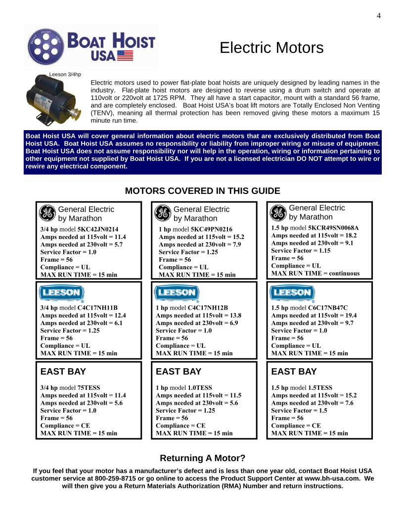
Electric motors used to power flat-plate boat hoists are uniquely designed by leading names in the industry. Flat-plate hoist motors are designed to reverse using a drum switch and operate at 110volt or 220volt at 1725 RPM. They all have a start capacitor, mount with a standard 56 frame, and are completely enclosed. Boat Hoist USA’s boat lift motors are Totally Enclosed Non Venting (TENV), meaning all thermal protection has been removed giving these motors a maximum 15 minute run time.
Leeson 3/4hp
Boat Hoist USA will cover general information about electric motors that are exclusively distributed from Boat Hoist USA. Boat Hoist USA assumes no responsibility or liability from improper wiring or misuse of equipment. Boat Hoist USA does not assume responsibility nor will help in the operation, wiring or information pertaining to other equipment not supplied by Boat Hoist USA. If you are not a licensed electrician DO NOT attempt to wire or rewire any electrical component.
MOTORS COVERED IN THIS GUIDE
Electric Motors
1 hp model C4C17NH12B Amps needed at 115volt = 13.8 Amps needed at 230volt = 6.9 Service Factor = 1.0 Frame = 56 Compliance = UL MAX RUN TIME = 15 min
3/4 hp model C4C17NH11B Amps needed at 115volt = 12.4 Amps needed at 230volt = 6.1 Service Factor = 1.25 Frame = 56 Compliance = UL MAX RUN TIME = 15 min
1.5 hp model C6C17NB47C Amps needed at 115volt = 19.4 Amps needed at 230volt = 9.7 Service Factor = 1.0 Frame = 56 Compliance = UL MAX RUN TIME = 15 min
General Electric by Marathon
3/4 hp model 5KC42JN0214 Amps needed at 115volt = 11.4 Amps needed at 230volt = 5.7 Service Factor = 1.0 Frame = 56 Compliance = UL MAX RUN TIME = 15 min
3/4 hp model 75TESS Amps needed at 115volt = 11.4 Amps needed at 230volt = 5.6 Service Factor = 1.0 Frame = 56 Compliance = CE MAX RUN TIME = 15 min
EAST BAY 1 hp model 1.0TESS Amps needed at 115volt = 11.5 Amps needed at 230volt = 5.6 Service Factor = 1.25 Frame = 56 Compliance = CE MAX RUN TIME = 15 min
EAST BAY 1.5 hp model 1.5TESS Amps needed at 115volt = 15.2 Amps needed at 230volt = 7.6 Service Factor = 1.5 Frame = 56 Compliance = CE MAX RUN TIME = 15 min
EAST BAY
General Electric by Marathon
1 hp model 5KC49PN0216 Amps needed at 115volt = 15.2 Amps needed at 230volt = 7.9 Service Factor = 1.25 Frame = 56 Compliance = UL MAX RUN TIME = 15 min
1.5 hp model 5KCR49SN0068A Amps needed at 115volt = 18.2 Amps needed at 230volt = 9.1 Service Factor = 1.15 Frame = 56 Compliance = UL MAX RUN TIME = continuous
General Electric by Marathon
Returning A Motor?
If you feel that your motor has a manufacturer’s defect and is less than one year old, contact Boat Hoist USA customer service at 800-259-8715 or go online to access the Product Support Center at www.bh-usa.com. We
will then give you a Return Materials Authorization (RMA) Number and return instructions.
4
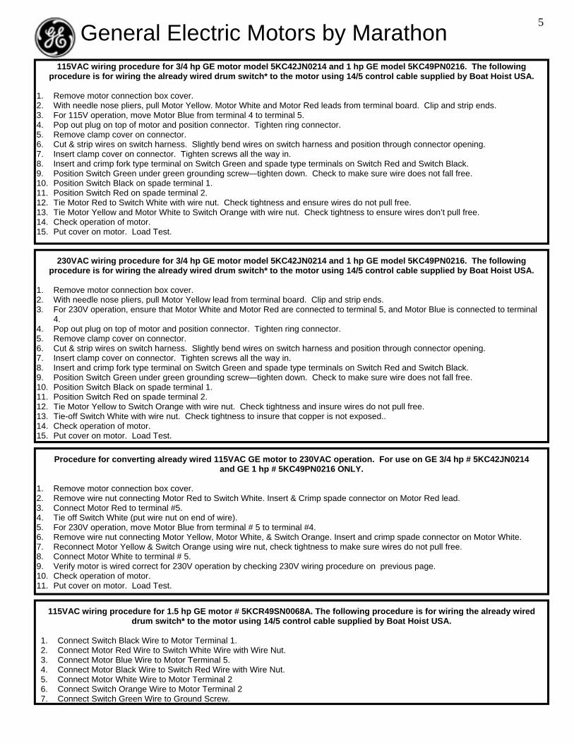
230VAC wiring procedure for 3/4 hp GE motor model 5KC42JN0214 and 1 hp GE model 5KC49PN0216. The following procedure is for wiring the already wired drum switch* to the motor using 14/5 control cable supplied by Boat Hoist USA.
1. Remove motor connection box cover. 2. With needle nose pliers, pull Motor Yellow lead from terminal board. Clip and strip ends. 3. For 230V operation, ensure that Motor White and Motor Red are connected to terminal 5, and Motor Blue is connected to terminal
4. 4. Pop out plug on top of motor and position connector. Tighten ring connector. 5. Remove clamp cover on connector. 6. Cut & strip wires on switch harness. Slightly bend wires on switch harness and position through connector opening. 7. Insert clamp cover on connector. Tighten screws all the way in. 8. Insert and crimp fork type terminal on Switch Green and spade type terminals on Switch Red and Switch Black. 9. Position Switch Green under green grounding screw—tighten down. Check to make sure wire does not fall free. 10. Position Switch Black on spade terminal 1. 11. Position Switch Red on spade terminal 2. 12. Tie Motor Yellow to Switch Orange with wire nut. Check tightness and insure wires do not pull free. 13. Tie-off Switch White with wire nut. Check tightness to insure that copper is not exposed.. 14. Check operation of motor. 15. Put cover on motor. Load Test.
General Electric Motors by Marathon
Procedure for converting already wired 115VAC GE motor to 230VAC operation. For use on GE 3/4 hp # 5KC42JN0214 and GE 1 hp # 5KC49PN0216 ONLY.
1. Remove motor connection box cover. 2. Remove wire nut connecting Motor Red to Switch White. Insert & Crimp spade connector on Motor Red lead. 3. Connect Motor Red to terminal #5. 4. Tie off Switch White (put wire nut on end of wire). 5. For 230V operation, move Motor Blue from terminal # 5 to terminal #4. 6. Remove wire nut connecting Motor Yellow, Motor White, & Switch Orange. Insert and crimp spade connector on Motor White. 7. Reconnect Motor Yellow & Switch Orange using wire nut, check tightness to make sure wires do not pull free. 8. Connect Motor White to terminal # 5. 9. Verify motor is wired correct for 230V operation by checking 230V wiring procedure on previous page. 10. Check operation of motor. 11. Put cover on motor. Load Test.
115VAC wiring procedure for 3/4 hp GE motor model 5KC42JN0214 and 1 hp GE model 5KC49PN0216. The following procedure is for wiring the already wired drum switch* to the motor using 14/5 control cable supplied by Boat Hoist USA.
1. Remove motor connection box cover. 2. With needle nose pliers, pull Motor Yellow. Motor White and Motor Red leads from terminal board. Clip and strip ends. 3. For 115V operation, move Motor Blue from terminal 4 to terminal 5. 4. Pop out plug on top of motor and position connector. Tighten ring connector. 5. Remove clamp cover on connector. 6. Cut & strip wires on switch harness. Slightly bend wires on switch harness and position through connector opening. 7. Insert clamp cover on connector. Tighten screws all the way in. 8. Insert and crimp fork type terminal on Switch Green and spade type terminals on Switch Red and Switch Black. 9. Position Switch Green under green grounding screw—tighten down. Check to make sure wire does not fall free. 10. Position Switch Black on spade terminal 1. 11. Position Switch Red on spade terminal 2. 12. Tie Motor Red to Switch White with wire nut. Check tightness and ensure wires do not pull free. 13. Tie Motor Yellow and Motor White to Switch Orange with wire nut. Check tightness to ensure wires don’t pull free. 14. Check operation of motor. 15. Put cover on motor. Load Test.
115VAC wiring procedure for 1.5 hp GE motor # 5KCR49SN0068A. The following procedure is for wiring the already wired drum switch* to the motor using 14/5 control cable supplied by Boat Hoist USA.
1. Connect Switch Black Wire to Motor Terminal 1. 2. Connect Motor Red Wire to Switch White Wire with Wire Nut. 3. Connect Motor Blue Wire to Motor Terminal 5. 4. Connect Motor Black Wire to Switch Red Wire with Wire Nut. 5. Connect Motor White Wire to Motor Terminal 2 6. Connect Switch Orange Wire to Motor Terminal 2 7. Connect Switch Green Wire to Ground Screw.
5
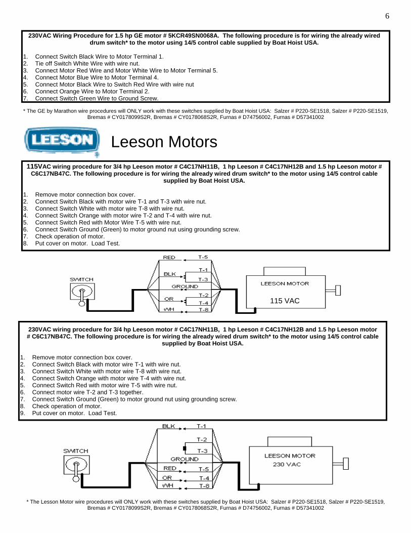
230VAC Wiring Procedure for 1.5 hp GE motor # 5KCR49SN0068A. The following procedure is for wiring the already wired drum switch* to the motor using 14/5 control cable supplied by Boat Hoist USA.
1. Connect Switch Black Wire to Motor Terminal 1. 2. Tie off Switch White Wire with wire nut. 3. Connect Motor Red Wire and Motor White Wire to Motor Terminal 5. 4. Connect Motor Blue Wire to Motor Terminal 4. 5. Connect Motor Black Wire to Switch Red Wire with wire nut 6. Connect Orange Wire to Motor Terminal 2. 7. Connect Switch Green Wire to Ground Screw.
* The GE by Marathon wire procedures will ONLY work with these switches supplied by Boat Hoist USA: Salzer # P220-SE1518, Salzer # P220-SE1519, Bremas # CY0178099S2R, Bremas # CY0178068S2R, Furnas # D74756002, Furnas # D57341002
Leeson Motors 115VAC wiring procedure for 3/4 hp Leeson motor # C4C17NH11B, 1 hp Leeson # C4C17NH12B and 1.5 hp Leeson motor #
C6C17NB47C. The following procedure is for wiring the already wired drum switch* to the motor using 14/5 control cable supplied by Boat Hoist USA.
1. Remove motor connection box cover. 2. Connect Switch Black with motor wire T-1 and T-3 with wire nut. 3. Connect Switch White with motor wire T-8 with wire nut. 4. Connect Switch Orange with motor wire T-2 and T-4 with wire nut. 5. Connect Switch Red with Motor Wire T-5 with wire nut. 6. Connect Switch Ground (Green) to motor ground nut using grounding screw. 7. Check operation of motor. 8. Put cover on motor. Load Test.
115 VAC
* The Lesson Motor wire procedures will ONLY work with these switches supplied by Boat Hoist USA: Salzer # P220-SE1518, Salzer # P220-SE1519, Bremas # CY0178099S2R, Bremas # CY0178068S2R, Furnas # D74756002, Furnas # D57341002
230VAC wiring procedure for 3/4 hp Leeson motor # C4C17NH11B, 1 hp Leeson # C4C17NH12B and 1.5 hp Leeson motor # C6C17NB47C. The following procedure is for wiring the already wired drum switch* to the motor using 14/5 control cable
supplied by Boat Hoist USA. 1. Remove motor connection box cover. 2. Connect Switch Black with motor wire T-1 with wire nut. 3. Connect Switch White with motor wire T-8 with wire nut. 4. Connect Switch Orange with motor wire T-4 with wire nut. 5. Connect Switch Red with motor wire T-5 with wire nut. 6. Connect motor wire T-2 and T-3 together. 7. Connect Switch Ground (Green) to motor ground nut using grounding screw. 8. Check operation of motor. 9. Put cover on motor. Load Test.
6
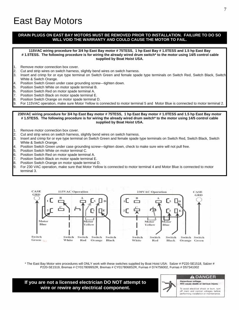
East Bay Motors DRAIN PLUGS ON EAST BAY MOTORS MUST BE REMOVED PRIOR TO INSTALLATION. FAILURE TO DO SO
WILL VOID THE WARRANTY AND COULD CAUSE THE MOTOR TO FAIL.
230VAC wiring procedure for 3/4 hp East Bay motor # 75TESS, 1 hp East Bay motor # 1.0TESS and 1.5 hp East Bay motor # 1.5TESS. The following procedure is for wiring the already wired drum switch* to the motor using 14/5 control cable
supplied by Boat Hoist USA. 1. Remove motor connection box cover. 2. Cut and strip wires on switch harness, slightly bend wires on switch harness. 3. Insert and crimp for or eye type terminal on Switch Green and female spade type terminals on Switch Red, Switch Black, Switch
White & Switch Orange. 4. Position Switch Green under case grounding screw—tighten down, check to make sure wire will not pull free. 5. Position Switch White on motor terminal C. 6. Position Switch Red on motor spade terminal A. 7. Position Switch Black on motor spade terminal E. 8. Position Switch Orange on motor spade terminal D. 9. For 230 VAC operation, make sure that Motor Yellow is connected to motor terminal 4 and Motor Blue is connected to motor
terminal 3.
115VAC wiring procedure for 3/4 hp East Bay motor # 75TESS, 1 hp East Bay # 1.0TESS and 1.5 hp East Bay # 1.5TESS. The following procedure is for wiring the already wired drum switch* to the motor using 14/5 control cable
supplied by Boat Hoist USA. 1. Remove motor connection box cover. 2. Cut and strip wires on switch harness, slightly bend wires on switch harness. 3. Insert and crimp for or eye type terminal on Switch Green and female spade type terminals on Switch Red, Switch Black, Switch
White & Switch Orange. 4. Position Switch Green under case grounding screw—tighten down. 5. Position Switch White on motor spade terminal B. 6. Position Switch Red on motor spade terminal A. 7. Position Switch Black on motor spade terminal E. 8. Position Switch Orange on motor spade terminal D. 9. For 115VAC operation, make sure Motor Yellow is connected to motor terminal 5 and Motor Blue is connected to motor terminal 2.
If you are not a licensed electrician DO NOT attempt to wire or rewire any electrical component.
* The East Bay Motor wire procedures will ONLY work with these switches supplied by Boat Hoist USA: Salzer # P220-SE1518, Salzer # P220-SE1519, Bremas # CY0178099S2R, Bremas # CY0178068S2R, Furnas # D74756002, Furnas # D57341002
7
INSTALLATION TIP #1
In most cases low voltage cannot be detected until the load is on the hoist. Have your installer lift the boat completely out of the water to ensure that Low voltage is not a problem.
INSTALLATION TIP #2
If you are experiencing low volt-age, your options are: • Replace the wire • Change the system from
115VAC to 230VAC • Compound the lift.
INSTALLATION TIP #3
Sometimes low voltage can be caused by your lift being in a bind. Refer to the Troubleshooting Guide on pages 13-14 of this Equipment Guide.
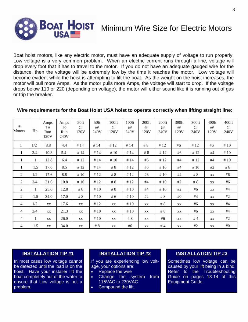
Minimum Wire Size for Electric Motors
Boat hoist motors, like any electric motor, must have an adequate supply of voltage to run properly. Low voltage is a very common problem. When an electric current runs through a line, voltage will drop every foot that it has to travel to the motor. If you do not have an adequate gauged wire for the distance, then the voltage will be extremely low by the time it reaches the motor. Low voltage will become evident while the hoist is attempting to lift the boat. As the weight on the hoist increases, the motor will pull more Amps. As the motor pulls more Amps, the voltage will start to drop. If the voltage drops below 110 or 220 (depending on voltage), the motor will either sound like it is running out of gas or trip the breaker.
Wire requirements for the Boat Hoist USA hoist to operate correctly when lifting straight line:
# Motors
Hp
Amps To
Run 120V
Amps To
Run 240V
50ft @
120V
50ft @
240V
100ft @
120V
100ft @
240V
200ft @
120V
200ft @
240V
300ft @
120V
300ft @
240V
400ft @
120V
400ft @
240V
1 1/2 8.8
5.4
# 14 # 14 # 14 # 12 # 12 # 12 # 10
# 10
# 10
# 8 #6 #6
2
2
2
2
4
4
4
4
1/2
1/2
3/4
3/4
1
1
1.5
1.5
17.6
21.6
25.6
34.0
xx
xx
xx
xx
8.8
10.8
12.8
17.0
17.6
21.3
26.0
34.0
# 12
# 12
# 12
# 12
# 12
# 10
# 10
# 10
# 10
# 10 # 10
# 10
# 10
# 10
# 8
# 8
# 10
# 10
# 8
# 8
# 8
# 6 # 8
# 8
# 8
# 8
# 8
# 8
# 8
# 10
# 10
xx
xx
xx
xx
xx
xx
xx
xx
xx
xx
xx
xx
xx
xx
xx
xx
xx
xx
xx
xx
xx
xx
xx
xx #6
#6
#6
#6
#6
#6
#6 #4
#4
#4
#4
#4
#4
#4
#2
#2
#2
#2
#2
#2 # 4
# 4
#6
#0
#0
1
1
1
3/4
1
1.5
10.8
12.8
17.0
4.4
6.4
8.5
# 14 # 14
# 14
# 14
# 14
# 14 # 12
# 12
# 12
# 12
# 12
# 12
# 12
# 10
# 10
# 10 # 10 # 8
# 8 #6
#6
#6
#4
#4
#4
#4
#2 # 8
8
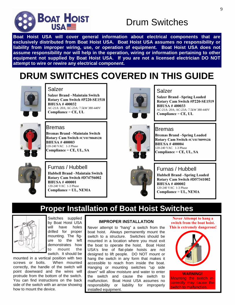
DRUM SWITCHES COVERED IN THIS GUIDE Salzer Salzer Brand –Maintain Switch Rotary Cam Switch #P220-SE1518 BHUSA # 400032 AC-21A: 20A; AC-23A: 7.5kW 380-440V Compliance = CE, UL
Salzer Brand –Spring Loaded Rotary Cam Switch #P220-SE1519 BHUSA # 400033 AC-21A: 20A; AC-23A: 7.5kW 380-440V Compliance = CE, UL
Salzer
Furnas / Hubbell Hubbell Brand –Maintain Switch Rotary Cam Switch #D74756002 BHUSA # 400001 120-240 VAC 1-3 Phase Compliance = UL, NEMA
Furnas / Hubbell Hubbell Brand –Spring Loaded Rotary Cam Switch #D57341002 BHUSA # 400002 120-240 VAC 1-3 Phase Compliance = UL, NEMA
Bremas Brand –Maintain Switch Rotary Cam Switch #CY0178068S2R BHUSA # 400003 120-240 VAC 1-3 Phase Compliance = CE, UL, SA
Bremas Bremas Brand –Spring Loaded Rotary Cam Switch #CY0178099S2R BHUSA # 400004 120-240 VAC 1-3 Phase Compliance = CE, UL, SA
Bremas
Proper Installation of Boat Hoist Switches Switches supplied by Boat Hoist USA will have holes drilled for proper mounting. The fig-ure to the left demonstrates how to mount the switch. It should be
mounted in a vertical position with two screws or bolts. When mounted correctly, the handle of the switch will point downward and the wires will protrude from the bottom of the switch. You can find instructions on the back side of the switch with an arrow showing how to mount the device.
WARNING! Mounting the switch in-correctly may cause the switch to malfunction.
Never Attempt to hang a switch from the boat hoist.
This is extremely dangerous!
IMPROPER INSTALLATION
Never attempt to “hang” a switch from the boat hoist. Always permanently mount the switch to a structure. Switches should be mounted in a location where you must exit the boat to operate the hoist. Boat Hoist USA’s line of flat-plate hoists are not designed to lift people. DO NOT mount or hang the switch in any form that makes it accessible to reach from inside the boat. Hanging or mounting switches “up side down” will allow moisture and water to enter the switch and cause the switch to malfunction. Boat Hoist USA assumes no responsibility or liability for improperly installed equipment.
Drum Switches
9
Boat Hoist USA will cover general information about electrical components that are exclusively distributed from Boat Hoist USA. Boat Hoist USA assumes no responsibility or liability from improper wiring, use, or operation of equipment. Boat Hoist USA does not assume responsibility nor will help in the operation, wiring or information pertaining to other equipment not supplied by Boat Hoist USA. If you are not a licensed electrician DO NOT attempt to wire or rewire any electrical component.
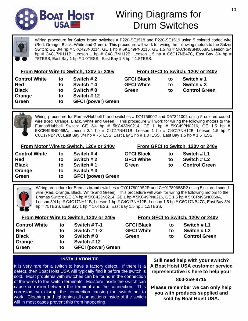
Wiring procedure for Furnas/Hubbell brand switches # D74756002 and D57341002 using 5 colored coded wire (Red, Orange, Black, White and Green). This procedure will work for wiring the following motors to the Furnas/Hubbell Switch: GE 3/4 hp # 5KC42JN0214, GE 1 hp # 5KC49PN0216, GE 1.5 hp # 5KCR49SN0068A, Leeson 3/4 hp # C4C17NH11B, Leeson 1 hp # C4C17NH12B, Leeson 1.5 hp # C6C17NB47C, East Bay 3/4 hp # 75TESS, East Bay 1 hp # 1.0TESS, East Bay 1.5 hp # 1.5TESS.
From Motor Wire to Switch, 120v or 240v
Control White to Switch # 4 Red to Switch # 2 Black to Switch # 1 Orange to Switch # 3 Green to GFCI (power) Green
From GFCI to Switch, 120v or 240v
GFCI Black to Switch # L1 GFCI White to Switch # L2 Green to Control Green
Still need help with your switch? A Boat Hoist USA customer service representative is here to help you!
800-259-8715
Please remember we can only help you with products supplied and
sold by Boat Hoist USA.
Wiring Diagrams for Drum Switches
Wiring procedure for Salzer brand switches # P220-SE1518 and P220-SE1519 using 5 colored coded wire (Red, Orange, Black, White and Green). This procedure will work for wiring the following motors to the Salzer Switch: GE 3/4 hp # 5KC42JN0214, GE 1 hp # 5KC49PN0216, GE 1.5 hp # 5KCR49SN0068A, Leeson 3/4 hp # C4C17NH11B, Leeson 1 hp # C4C17NH12B, Leeson 1.5 hp # C6C17NB47C, East Bay 3/4 hp # 75TESS, East Bay 1 hp # 1.0TESS, East Bay 1.5 hp # 1.5TESS.
From Motor Wire to Switch, 120v or 240v
Control White to Switch # 2 Red to Switch # 4 Black to Switch # 8 Orange to Switch # 12 Green to GFCI (power) Green
From GFCI to Switch, 120v or 240v
GFCI Black to Switch # 1 GFCI White to Switch # 3 Green to Control Green
Wiring procedure for Bremas brand switches # CY0178099S2R and CY0178068SR2 using 5 colored coded wire (Red, Orange, Black, White and Green). This procedure will work for wiring the following motors to the Bremas Switch: GE 3/4 hp # 5KC42JN0214, GE 1 hp # 5KC49PN0216, GE 1.5 hp # 5KCR49SN0068A, Leeson 3/4 hp # C4C17NH11B, Leeson 1 hp # C4C17NH12B, Leeson 1.5 hp # C6C17NB47C, East Bay 3/4 hp # 75TESS, East Bay 1 hp # 1.0TESS, East Bay 1.5 hp # 1.5TESS.
From Motor Wire to Switch, 120v or 240v
Control White to Switch # T-1 Red to Switch # T-2 Black to Switch # 8 Orange to Switch # 12 Green to GFCI (power) Green
From GFCI to Switch, 120v or 240v
GFCI Black to Switch # L1 GFCI White to Switch # L2 Green to Control Green
INSTALLATION TIP
It is very rare for a switch to have a factory defect. If there is a defect, then Boat Hoist USA will typically find it before the switch is sold. Most problems with switches can be found in the connection of the wires to the switch terminals. Moisture inside the switch can cause corrosion between the terminal and the connection. This corrosion can disrupt the connection causing the switch not to work. Cleaning and tightening all connections inside of the switch will in most cases prevent this from happening.
10
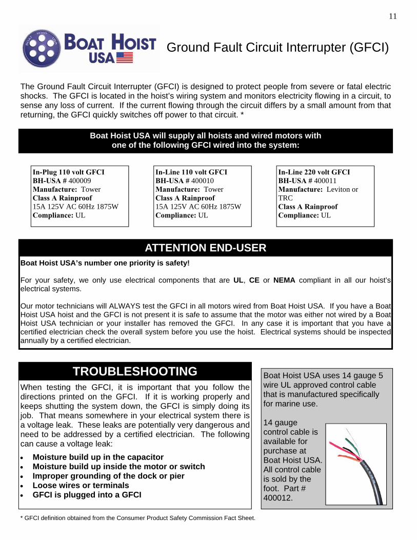
Boat Hoist USA will supply all hoists and wired motors with one of the following GFCI wired into the system:
ATTENTION END-USER Boat Hoist USA’s number one priority is safety! For your safety, we only use electrical components that are UL, CE or NEMA compliant in all our hoist’s electrical systems. Our motor technicians will ALWAYS test the GFCI in all motors wired from Boat Hoist USA. If you have a Boat Hoist USA hoist and the GFCI is not present it is safe to assume that the motor was either not wired by a Boat Hoist USA technician or your installer has removed the GFCI. In any case it is important that you have a certified electrician check the overall system before you use the hoist. Electrical systems should be inspected annually by a certified electrician.
TROUBLESHOOTING When testing the GFCI, it is important that you follow the directions printed on the GFCI. If it is working properly and keeps shutting the system down, the GFCI is simply doing its job. That means somewhere in your electrical system there is a voltage leak. These leaks are potentially very dangerous and need to be addressed by a certified electrician. The following can cause a voltage leak:
• Moisture build up in the capacitor • Moisture build up inside the motor or switch • Improper grounding of the dock or pier • Loose wires or terminals • GFCI is plugged into a GFCI
Boat Hoist USA uses 14 gauge 5 wire UL approved control cable that is manufactured specifically for marine use. 14 gauge control cable is available for purchase at Boat Hoist USA. All control cable is sold by the foot. Part # 400012.
Ground Fault Circuit Interrupter (GFCI)
The Ground Fault Circuit Interrupter (GFCI) is designed to protect people from severe or fatal electric shocks. The GFCI is located in the hoist’s wiring system and monitors electricity flowing in a circuit, to sense any loss of current. If the current flowing through the circuit differs by a small amount from that returning, the GFCI quickly switches off power to that circuit. *
In-Plug 110 volt GFCI BH-USA # 400009 Manufacture: Tower Class A Rainproof 15A 125V AC 60Hz 1875W Compliance: UL
In-Line 110 volt GFCI BH-USA # 400010 Manufacture: Tower Class A Rainproof 15A 125V AC 60Hz 1875W Compliance: UL
In-Line 220 volt GFCI BH-USA # 400011 Manufacture: Leviton or TRC Class A Rainproof Compliance: UL
11
* GFCI definition obtained from the Consumer Product Safety Commission Fact Sheet.
Troubleshooting My boat hoist runs until the boat starts to come out of the water and then stops. Why can’t my hoist lift my boat out of the water? The hoist “stopping” is usually caused by low of voltage. An electric motor uses voltage as its fuel, and when it does not have enough it will simply stop. Even though you have 115 or 240 volts at the plug, the real test is to see if your electrical system can maintain this voltage while the hoist is being used. As the hoist begins to pick up the boat the motor starts to experience a load and works harder. The harder the motor works the more AMPS the motor will need. As the motor uses more AMPS the voltage will begin to drop, eventu-ally stopping the motor. This issue is typically a result of one of the following: • Inadequate voltage supply: Voltage will drop every foot that it travels from the main breaker. On long runs, heavier gauge wire
is needed to help maintain the strength of the voltage from the main panel to the outlet. A wire chart is supplied on page 8 of this guide. Check the gauge of wire verses the length it has to run, then check the chart to make sure you have the right wire needed. If you are trying to lift the boat using extension cords or a generator, then chances are you are not meeting voltage requirements.
• Lifting to much weight: Lifting more weight than your hoist is designed to lift can cause the motor to experience low voltage. In this situation, the motor reached its max capacity. In some cases, with extreme drops in voltage the GFCI will trip and turn the power off. All hoists are rated and will lift up to their rating with no problems. It is a common mistake to underestimate the weight that the hoist is having to lift. Please refer to page 4 to calculate how much you are lifting.
• Improper installation of equipment or general maintenance: Improper installation, causing the unit to get in a bind will actually build unneeded friction in the lift. Friction is translated to the motor as more weight, thus the AMPS to voltage process take effect. Improperly installed equipment can also effect the rating of the lift. For example, the pulleys or blocks used in the system need to be ball bearing. Blocks that are not ball bearing will cause friction that is translated into weight. Improper grease on the gears and other parts of the lift can cause unneeded friction as well. Just remember this, flat-plate hoists have been lifting boats for over 50 years, it is probably NOT the hoist that is malfunctioning.
I’ve never had this problem with my old hoist and the hoist in the next stall is operating fine, even with the same boat. What’s wrong with my new hoist? Chances are the older hoist and the hoist in the other stall operates fine because it is installed correctly or has different voltage require-ments. A 3/4 hp motor will actually lift more with adequate power than a 1 hp motor can lift with inadequate power. Older lift systems typically used smaller gauge wire because most lift motors were 3/4 hp. Today, as boats get heaver and larger, more powerful motors are required and some older systems cannot provide the power. Voltage will drop every foot it travels and the line between adequate voltage and low voltage could be reached between motors just 10 feet apart. My Hoist is making a clicking noise. Why? This rhythmic clicking noise can sometimes be experienced with new hoists, especially hoists that are lifting heavy boats. Do not be alarmed! The hoist is not in danger of failing. The noise you are hearing is caused by a release of pressure as the worm gear releases from the worm. In most cases this noise will eventually disappear all together as the gears wear into each other (brake in period). Ad-justing the belts, tightening the collars, and greasing the unit may also help silence the clicking noise. Why is my Hoist is making a loud squeal when lifting or lowering the boat? A hoist making this type of noise is not normal and you should stop using the lift until the problem is solved. This noise is typically heard on hoists that have been improperly installed or not greased. In both situations serious damage could be caused to the hoist. Review the installation guides available in this guide and grease the unit using the correct type of grease. (See pages 6-7) Why is my Hoist is making a harmonic sound when the boat is being lowered? A hoist making this type of noise is probably in the break-in period. Look at the arrow on the gear. The arrow points to the smooth side of the gear and should be moving in that direction as the boat is being lifted. The rough side of the gear is being used while the boat is being lowered. As the worm turns on this rough side, it is actually acting like sand paper and smoothing the gear. During this period a harmonic tone will sometimes be heard. The sound will eventually go away as the hoist gets broken-in. The set screw on the pulley has loosened and keeps falling out. What do I do? If the pulleys are not aligned or the unit is experiencing heavy vibration, the set screws can loosen. If the unit is mounted vertically the screw can fall out completely. Make sure your pulleys are lined up and that there is nothing in the installation that could cause vibra-tion to the gear plate. If this does not work, use Lock Tight on the set screws. I can see metal shavings in the grease around the worm. Is that the sign of a problem? This is definitely not a typical or safe situation for a Hoist. What is happening is that the 96 tooth worm gear has moved and the hob on the gear is not lining up with the tooth of the worm. The softer metal is now being cut by the stronger metal. This happens because the system is not installed correctly and the drive pipe that acts like a lever has moved the gear. This typically happens when an uneven load is put on the pipe and the load is transferred into the gear sleeve. The hoist does not need to be used until the problem has been solved. Refer to this guide for proper installations and tips. (See pages 6-7)
12
Troubleshooting
The motor will not turn, even without a load. The motor just hums. Why? This scenario sounds like your capacitor has stopped working. The electric motors supplied by Boat Hoist USA all work with start ca-pacitors. The capacitor is actually a battery that holds a charge. This charge is designed to “jump” start the motor. You can diagnose this problem by taking the motor off the hoist, turn it on, and as it starts to hum spin the shaft. If the motor starts running then it is most likely the capacitor. By spinning the shaft you simulated a capacitor. Unfortunately a capacitor is not considered a manufacturer’s de-fect and is the responsibility of the customer to replace it if one goes bad. Don’t worry, it is as easy as changing a battery! Contact the Boat Hoist USA sales department to order a new capacitor. The motor makes a loud grinding sound when turned on. Why? This grinding sound is originating from the bearings that are inside the motor. There are two probable causes to this sound: • The motor was dropped and damaged, causing a bearing or two to pop out of the track. Before installing a lift it is the customers
responsibility to check the condition of equipment, especially after equipment has been shipped. Always plug the motor in and run it in both directions to ensure the motor will run smooth and quite. Immediately contact the Boat Hoist USA customer service de-partment if your motor is not operating properly before you install the lift.
• The bearings can rust over time, especially in salt water environments. If the motor has ever been submerged or is directly ex-posed to this environment, the bearings could be rusted. It is the customers responsibility to ensure their motors are properly pro-tected against the environment.
Why does my motor smoke when it is turned on? If this is the first time the motor has been used and the motor came wired from Boat Hoist USA, un-plug it and contact Boat Hoist USA customer service at 800-259-8715. If the motor was wired by any other party other than Boat Hoist USA, un-plug the motor and care-fully review all wiring instructions to see if the motor has been wired properly. If this is a motor that has been in service for some time and has been operating fine until now, then chances are the motor has overheated and the windings are burning. Boat hoist motors are enclosed to help protect them from the environment and foreign debris. Since these motors cannot vent, they will overheat with about 15 minutes of continuous running or continual start and stop without at least 5 minute cool down between each cycle. Be careful when troubleshooting a motor as you can burn the windings which are not covered under the warranty. Why isn't an overheated motor covered under warranty? Overheating is the result when too many Amps run through the motor causing the copper windings inside a motor to heat up and burn. Once this has happened the motor is ruined. Boat Hoist USA will warranty equipment for motor defects that originated from the factory. Since windings are new from the factory and can only be burned as a result from the user or an act of God (lightening), burned wind-ings cannot be covered under the warranty. What will cause my motor to overheat and ruin? The following can cause a motor to overheat and possibly damage or burn the windings: • Running the motor with an inadequate voltage supply. • Running the motor continually for more than 15 minutes at a time. • Turning the motor on and off in rapid succession (this can be easy done with a spring loaded switch or remote control). • Exceeding the motor lift rating. • A voltage surge such as lightning strike. These are just a few common occurrences that can damage an electric motor. In any case the motor will need to be replaced. How can I tell if my motor has burned windings? The most obvious sign is a smoking motor. If the motor has worked properly before, chances are the windings have been slowly over-heating over time. With every use the windings slowly burn and become so damaged that they begin to smoke. Another quick way to tell is it to UNPLUG the motor and remove the access plate. If the motor has been overheating, burn marks and/or a burn smell will be evident. In any case the motor will need to be replaced. I have replaced my motor and I’m using my existing switch. When I turn the new motor on it will only run in one direction and I know the motor is wired correctly per Boat Hoist USA directions. What is the problem? Chances are the existing switch and wire harness is not supplied by Boat Hoist USA. These directions will only work with these switches: Salzer # P220-21383-A02, Salzer # P220-21404-A02, Bremas # CY0178099S2R, Bremas # CY0178068S2R, Furnas # A14D, Furnas # A14Dx599U, Furnas # A14Y, Furnas # A14YX599. If you have any other switch, Boat Hoist USA will not be able to help you. If you are interested in purchasing one of the switches list above, contact a Boat Hoist USA sales representative at 800-259-8715.
13
LIFETIME WARRANTY Gear Plate Assembly
(GPA)
GPA WARRANTY REGISTRATION FORM
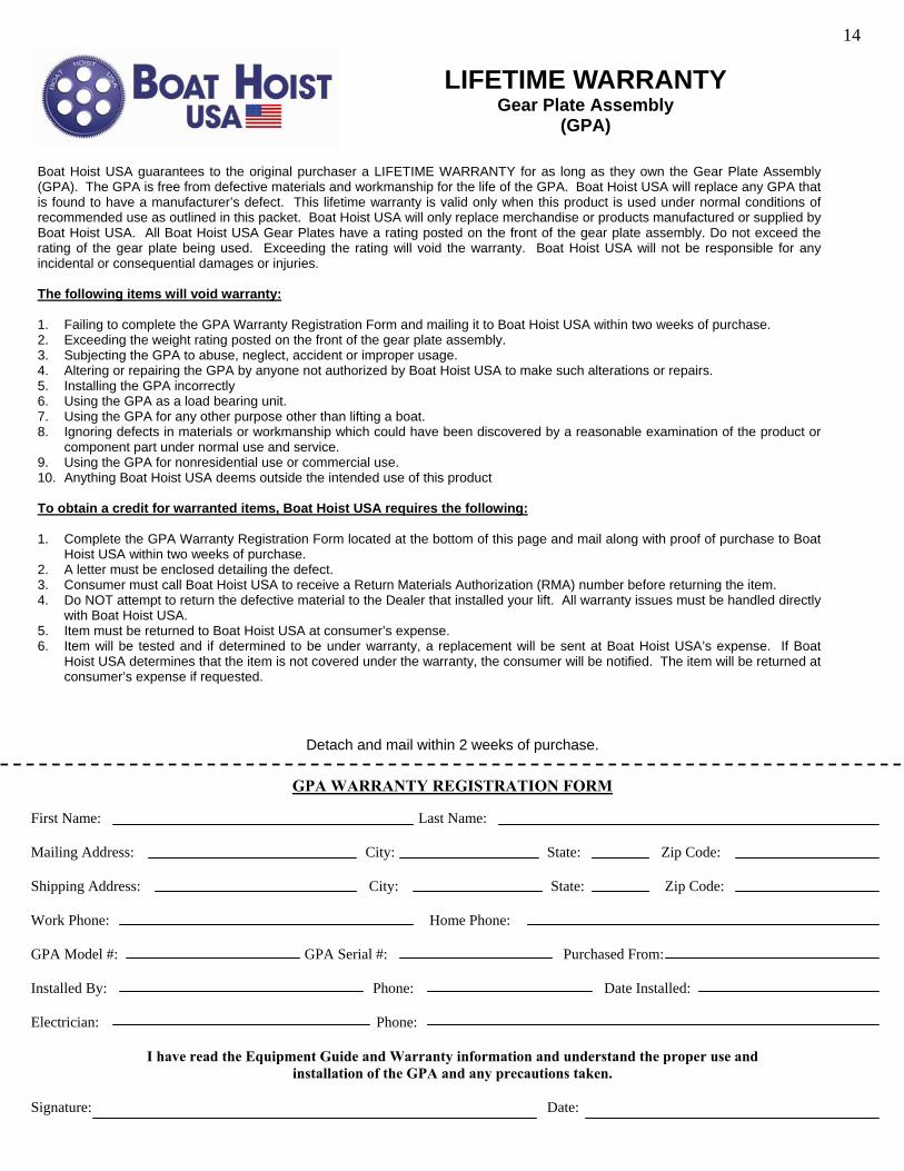
Boat Hoist USA guarantees to the original purchaser a LIFETIME WARRANTY for as long as they own the Gear Plate Assembly (GPA). The GPA is free from defective materials and workmanship for the life of the GPA. Boat Hoist USA will replace any GPA that is found to have a manufacturer’s defect. This lifetime warranty is valid only when this product is used under normal conditions of recommended use as outlined in this packet. Boat Hoist USA will only replace merchandise or products manufactured or supplied by Boat Hoist USA. All Boat Hoist USA Gear Plates have a rating posted on the front of the gear plate assembly. Do not exceed the rating of the gear plate being used. Exceeding the rating will void the warranty. Boat Hoist USA will not be responsible for any incidental or consequential damages or injuries. The following items will void warranty: 1. Failing to complete the GPA Warranty Registration Form and mailing it to Boat Hoist USA within two weeks of purchase. 2. Exceeding the weight rating posted on the front of the gear plate assembly. 3. Subjecting the GPA to abuse, neglect, accident or improper usage. 4. Altering or repairing the GPA by anyone not authorized by Boat Hoist USA to make such alterations or repairs. 5. Installing the GPA incorrectly 6. Using the GPA as a load bearing unit. 7. Using the GPA for any other purpose other than lifting a boat. 8. Ignoring defects in materials or workmanship which could have been discovered by a reasonable examination of the product or
component part under normal use and service. 9. Using the GPA for nonresidential use or commercial use. 10. Anything Boat Hoist USA deems outside the intended use of this product To obtain a credit for warranted items, Boat Hoist USA requires the following: 1. Complete the GPA Warranty Registration Form located at the bottom of this page and mail along with proof of purchase to Boat
Hoist USA within two weeks of purchase. 2. A letter must be enclosed detailing the defect. 3. Consumer must call Boat Hoist USA to receive a Return Materials Authorization (RMA) number before returning the item. 4. Do NOT attempt to return the defective material to the Dealer that installed your lift. All warranty issues must be handled directly
with Boat Hoist USA. 5. Item must be returned to Boat Hoist USA at consumer’s expense. 6. Item will be tested and if determined to be under warranty, a replacement will be sent at Boat Hoist USA’s expense. If Boat
Hoist USA determines that the item is not covered under the warranty, the consumer will be notified. The item will be returned at consumer’s expense if requested.
First Name: Last Name: Mailing Address: City: State: Zip Code: Shipping Address: City: State: Zip Code: Work Phone: Home Phone: GPA Model #: GPA Serial #: Purchased From: Installed By: Phone: Date Installed: Electrician: Phone:
I have read the Equipment Guide and Warranty information and understand the proper use and installation of the GPA and any precautions taken.
Signature: Date:
Detach and mail within 2 weeks of purchase.
14
LIMITED WARRANTY Motor & Wire Harness
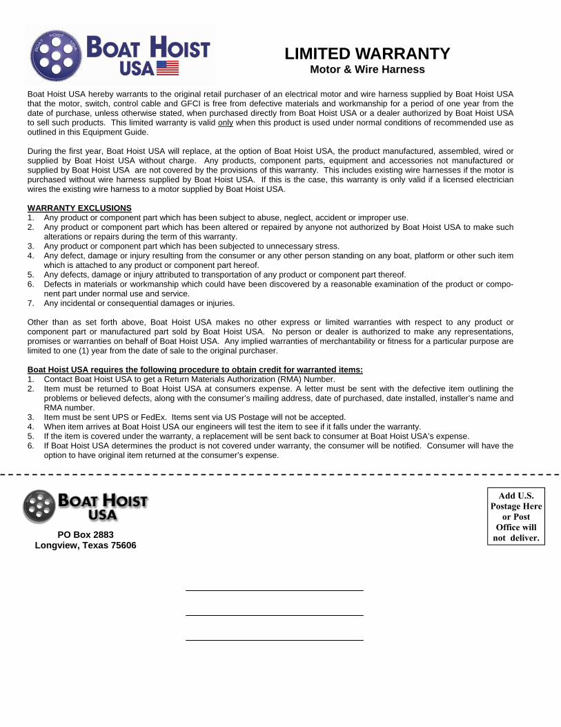
Boat Hoist USA hereby warrants to the original retail purchaser of an electrical motor and wire harness supplied by Boat Hoist USA that the motor, switch, control cable and GFCI is free from defective materials and workmanship for a period of one year from the date of purchase, unless otherwise stated, when purchased directly from Boat Hoist USA or a dealer authorized by Boat Hoist USA to sell such products. This limited warranty is valid only when this product is used under normal conditions of recommended use as outlined in this Equipment Guide. During the first year, Boat Hoist USA will replace, at the option of Boat Hoist USA, the product manufactured, assembled, wired or supplied by Boat Hoist USA without charge. Any products, component parts, equipment and accessories not manufactured or supplied by Boat Hoist USA are not covered by the provisions of this warranty. This includes existing wire harnesses if the motor is purchased without wire harness supplied by Boat Hoist USA. If this is the case, this warranty is only valid if a licensed electrician wires the existing wire harness to a motor supplied by Boat Hoist USA. WARRANTY EXCLUSIONS 1. Any product or component part which has been subject to abuse, neglect, accident or improper use. 2. Any product or component part which has been altered or repaired by anyone not authorized by Boat Hoist USA to make such
alterations or repairs during the term of this warranty. 3. Any product or component part which has been subjected to unnecessary stress. 4. Any defect, damage or injury resulting from the consumer or any other person standing on any boat, platform or other such item
which is attached to any product or component part hereof. 5. Any defects, damage or injury attributed to transportation of any product or component part thereof. 6. Defects in materials or workmanship which could have been discovered by a reasonable examination of the product or compo-
nent part under normal use and service. 7. Any incidental or consequential damages or injuries. Other than as set forth above, Boat Hoist USA makes no other express or limited warranties with respect to any product or component part or manufactured part sold by Boat Hoist USA. No person or dealer is authorized to make any representations, promises or warranties on behalf of Boat Hoist USA. Any implied warranties of merchantability or fitness for a particular purpose are limited to one (1) year from the date of sale to the original purchaser. Boat Hoist USA requires the following procedure to obtain credit for warranted items: 1. Contact Boat Hoist USA to get a Return Materials Authorization (RMA) Number. 2. Item must be returned to Boat Hoist USA at consumers expense. A letter must be sent with the defective item outlining the
problems or believed defects, along with the consumer’s mailing address, date of purchased, date installed, installer’s name and RMA number.
3. Item must be sent UPS or FedEx. Items sent via US Postage will not be accepted. 4. When item arrives at Boat Hoist USA our engineers will test the item to see if it falls under the warranty. 5. If the item is covered under the warranty, a replacement will be sent back to consumer at Boat Hoist USA’s expense. 6. If Boat Hoist USA determines the product is not covered under warranty, the consumer will be notified. Consumer will have the
option to have original item returned at the consumer’s expense.
PO Box 2883 Longview, Texas 75606
Add U.S. Postage Here
or Post Office will
not deliver.