EQUIPMENT GENERAL PROVISIONS 1. GENERAL 1 · PDF file.1 Latest revision of AWWA D100. .2...
52
City of Winnipeg Water Treatment Program Section 11000 Construction of Site Utilities Page 1 of 9 Bid Opportunity No. 94-2007 April 2007 EQUIPMENT GENERAL PROVISIONS 1. GENERAL 1.1 Requirements .1 The provisions of this Section shall apply to all equipment except where otherwise indicated. .2 Substantiating calculations and Drawings shall be submitted at the time of submittal. 1.2 Reference Specifications, Codes, and Standards .1 Equipment shall be in accordance with the latest edition of the following standards, as applicable and as indicated in each equipment Specification: .1 ASTM .2 ANSI .3 ASME .4 AWWA .5 ASHRAE .6 AWS .7 NFPA .8 FS .9 NEMA .10 Manufacturer's published recommendations and Specifications. .11 General Industry Safety Orders (OSHA). .12 CSA .13 ULC .2 The following standards are referenced in this Section: .1 ANSI B16.1 - Cast Iron Pipe Flanges and Flanged Fittings, Class 25, 125, 250, and 800. .2 ANSI B16.5 - Pipe Flanges and Flanged Fittings, Steel, Nickel Alloy and other Special Alloys. .3 ANSI B46.1 - Surface Texture.
Transcript of EQUIPMENT GENERAL PROVISIONS 1. GENERAL 1 · PDF file.1 Latest revision of AWWA D100. .2...
City of Winnipeg Water Treatment Program Section 11000 Construction of Site Utilities Page 1 of 9 Bid Opportunity No. 94-2007 April 2007
EQUIPMENT GENERAL PROVISIONS
1. GENERAL
1.1 Requirements
.1 The provisions of this Section shall apply to all equipment except where otherwise indicated.
.2 Substantiating calculations and Drawings shall be submitted at the time of submittal.
1.2 Reference Specifications, Codes, and Standards
.1 Equipment shall be in accordance with the latest edition of the following standards, as applicable and as indicated in each equipment Specification:
.1 ASTM
.2 ANSI
.3 ASME
.4 AWWA
.5 ASHRAE
.6 AWS
.7 NFPA
.8 FS
.9 NEMA
.10 Manufacturer's published recommendations and Specifications.
.11 General Industry Safety Orders (OSHA).
.12 CSA
.13 ULC
.2 The following standards are referenced in this Section:
.1 ANSI B16.1 - Cast Iron Pipe Flanges and Flanged Fittings, Class 25, 125, 250, and 800.
.2 ANSI B16.5 - Pipe Flanges and Flanged Fittings, Steel, Nickel Alloy and other Special Alloys.
.3 ANSI B46.1 - Surface Texture.
City of Winnipeg Water Treatment Program Section 11000 Construction of Site Utilities Page 2 of 9 Bid Opportunity No. 94-2007 April 2007
EQUIPMENT GENERAL PROVISIONS
.4 ASME B1.20.1 - General Purpose Pipe Threads (Inch).
.5 ASME B31.1 - Power Piping.
.6 AWWA C206 - Field Welding of Steel Water Pipe.
.7 AWWA C207 - Steel Pipe Flanges for Waterworks Service - Sizes 4 In. Through 144 In. (100 mm through 3,600 mm).
.8 AWWA D100 - Welded Steel Tanks for Water Storage.
.9 ASTM A 48 - Gray Iron Castings.
.10 ASTM A 108 - Steel Bars, Carbon, Cold-Finished, Standard Quality.
1.3 Contractor Submittals
.1 Shop Drawings: Furnish submittals in accordance with Section 01300 - Submittals.
.2 Equipment Installation: Complete all documentation as required within Section 01650 – Equipment Installation.
.3 Manuals: Provide manuals as specified within Section 01730 – Operation & Maintenance Manuals.
.4 Spare Parts List: A spare parts list complete with the name, address, and telephone number of the nearest distributor for each piece of equipment shall be provided. Include current prices for each spare part.
1.4 Quality Assurance
.1 Costs: Pay all costs of inspection, testing, adjustment, and instruction services performed by Manufacturer’s representatives. The City will pay for power and water.
.2 Quality and Tolerances: Tolerances and clearances shall be as shown on the Shop Drawings and shall be closely adhered to.
.1 Machine Work shall in all cases be of high-grade workmanship and finish, with due consideration to the special nature or function of the parts. Members without milled ends and which are to be framed to other steel parts of the structure may have a variation in the detailed length of not greater than 1.5 mm for members 10 m or less in length, and not greater than 3 mm for members over 10 m in length.
.2 Castings shall be homogeneous and free from non-metallic inclusions and defects. Surfaces of castings which are not machined shall be cleaned to remove foundry irregularities. Casting defects not exceeding 12.5% of the total thickness and where defects will not affect the strength and serviceability of the casting may be repaired by approved welding procedures.
City of Winnipeg Water Treatment Program Section 11000 Construction of Site Utilities Page 3 of 9 Bid Opportunity No. 94-2007 April 2007
EQUIPMENT GENERAL PROVISIONS
.3 All materials shall meet the physical and mechanical properties in accordance with the reference standards.
.3 Machine Finish: The type of finish shall be the most suitable for the application and shall be shown in micro-inches in accordance with ANSI B46.1. The following finishes shall be used:
.1 Surface roughness not greater than 63 µin shall be required for all surfaces in sliding contact.
.2 Surface roughness not greater than 250 µin shall be required for surfaces in contact where a tight joint is not required.
.3 Rough finish not greater than 500 µin shall be required for other machined surfaces.
.4 Contact surfaces of shafts and stems which pass through stuffing boxes and contact surfaces of bearings shall be finished to not greater than 32 µin.
2. PRODUCTS
2.1 General Requirements
.1 Noise Level: When in operation, no single piece of equipment shall exceed the OSHA noise level requirement of 85 dBA for one (1) hour exposure per day.
.2 Drive Trains and Service Factors: Service factors shall be applied in the selection or design of mechanical power transmission components. All components of drive train assemblies between the prime mover and the driven equipment shall be designed and rated to deliver the maximum peak or starting torque, speed, and horsepower. All of the applicable service factors shall be considered, such as mechanical motors, load class, start frequency, ventilation, ambient temperature, and fan factors. Drive train components include couplings, shafts, gears and gear drives, drive chains, sprockets, and V-belt drives. Unless otherwise indicated, a service factor of 1 and a uniform load classification for submersible pumps shall be used.
.3 Mechanical Service Factors
Mechanical Service Factors
Electric Motor Uniform 1.25 Moderate Shock 1.50 Heavy Shock 2.00
.4 For thermal rating adjustments such as start frequency, ambient temperature, and hourly duty cycle factor, ventilation factor, and fan factor, refer to gear Manufacturer sizing information.
City of Winnipeg Water Treatment Program Section 11000 Construction of Site Utilities Page 4 of 9 Bid Opportunity No. 94-2007 April 2007
EQUIPMENT GENERAL PROVISIONS
.5 Where load classifications are not indicated, service factors based on AGMA 514.02 shall be used for standard load classifications and service factors for flexible couplings.
.6 Welding: Unless otherwise indicated, welding shall conform to the following:
.1 Latest revision of AWWA D100.
.2 Latest revision of AWWA C206.
.3 Composite fabricated steel assemblies that are to be erected or installed inside a hydraulic structure, including any fixed or movable structural components of mechanical equipment, shall have continuous seal welds to prevent entrance of air or moisture.
.4 Welding shall be by the metal-arc method or gas-shielded arc method as described in the AWS "Welding Handbook" as supplemented by other pertinent standards of the AWS. Qualification of welders shall be in accordance with the AWS Standards.
.5 In assembly and during welding, the component parts shall be adequately clamped, supported, and restrained to minimize distortion and for control of dimensions. Weld reinforcement shall be as specified by the AWS code. Upon completion of welding, weld splatter, flux, slag, and burrs left by attachments shall be removed. Welds shall be repaired to produce a workmanlike appearance, with uniform weld contours and dimensions. Sharp corners of material that is to be painted or coated shall be ground to a minimum of 0.8 mm (1/32 inch) on the flat.
.7 Protective Coating: Equipment shall be painted or coated as specified within each equipment Specification unless otherwise indicated. Non-ferrous metal and corrosion-resisting steel surfaces shall be coated with food grade grease or lubricating oil. Coated surfaces shall be protected from abrasion or other damage during handling, testing, storing, assembly, and shipping.
.8 Protection of Equipment: Equipment shall be boxed, crated, or otherwise protected from damage and moisture during shipment, handling, and storage. Equipment shall be protected from exposure to corrosive fumes and shall be kept thoroughly dry at all times. Equipment delivered to the Site with rust or corroded parts shall be rejected.
.9 Vibration Isolators: Air compressors, blowers, engines, inline fans shall be provided with restrained spring-type vibration isolators or pads per Manufacturer's written recommendations. Vibration isolations shall be provided with seismic restraint.
.10 Controls: Equipment and system controls shall be in accordance with Division 17 – Instrumentation.
2.2 Equipment Supports
.1 Equipment Supports: Unless otherwise indicated, equipment supports, anchors, and restrainers shall be adequately designed for static, dynamic, wind, and seismic loads. The design horizontal seismic force shall be the greater of: that noted in the general structural
City of Winnipeg Water Treatment Program Section 11000 Construction of Site Utilities Page 5 of 9 Bid Opportunity No. 94-2007 April 2007
EQUIPMENT GENERAL PROVISIONS
notes or as required by the governing building code, or 10% of gravity. Submitted design calculations for equipment supports shall bear the signature and seal of a Professional Engineer registered in the Province of Manitoba, unless otherwise indicated.
2.3 Couplings
.1 Mechanical couplings shall be provided between the driver and the driven equipment. Flexible couplings shall be provided between the driver and the driven equipment to accommodate slight angular misalignment, parallel misalignment, end float, and to cushion shock loads. Unless otherwise indicated or recommended by the Manufacturer, coupling type shall be furnished with the respective equipment as follows:
Equipment Type Coupling Type Direct or driven pumps Gear or flexible spring
.2 Each coupling size shall be determined based on the rated horsepower of the motor, speed of the shaft, and the load classification service factor. The equipment Manufacturer shall select or recommend the size and type of coupling required to suit each specific application.
.3 Differential Settlement: Where differential settlement between the driver and the driven equipment may occur, two (2) sets of universal type couplings shall be provided.
.4 Taper-Lock or equal bushings may be used to provide for easy installation and removal of shafts of various diameters.
2.4 Shafting
.1 General: Shafting shall be continuous between bearings and shall be sized to transmit the power required. Keyways shall be accurately cut in line. Shafting shall not be turned down at the ends to accommodate bearings or sprockets whose bore is less than the diameter of the shaft. Shafts shall rotate in the end bearings and shall be turned and polished, straight, and true.
.2 Design Criteria: All shafts shall be designed to carry the steady state and transient loads suitable for unlimited number of load applications, in accordance with ASME B106.1M, - Design of Transmission Shafting. Where shafts are subjected to fatigue stresses, such as frequent start and stop cycles, the mean stress shall be determined by using the modified Goodman Diagram. The maximum torsional stress shall not exceed the endurance limit of the shaft after application of the factor of safety of 2 in the endurance limit and the stress concentration factor of the fillets in the shaft and keyway. Stress concentration factor shall be in accordance with ASME Standard B17.1 - Keys and Keyseats.
.3 Materials: Shafting materials shall be appropriate for the type of service and torque transmitted. Environmental elements such as corrosive gases, moisture, and fluids shall be taken into consideration. Materials shall be as indicated unless furnished as part of an equipment assembly:
.1 Low carbon cold-rolled steel shafting shall conform to ASTM A108, Grade 1018.
City of Winnipeg Water Treatment Program Section 11000 Construction of Site Utilities Page 6 of 9 Bid Opportunity No. 94-2007 April 2007
EQUIPMENT GENERAL PROVISIONS
.2 Medium carbon cold-rolled shafting shall conform to ASTM A108, Grade 1045.
.3 Other grades of carbon steel alloys shall be suitable for service and load.
.4 Corrosion-resistant shafting shall be stainless steel or Monel, whichever is most suitable for the intended service.
.4 Differential Settlement: Where differential settlement between the driver and the driven equipment may occur, a shaft of sufficient length with two (2) sets of universal type couplings shall be provided.
2.5 Sprockets
.1 General: Sprockets shall be used in conjunction with chain drives and chain-type material handling equipment.
.2 Materials: Unless otherwise indicated, materials shall be as follows:
.1 Sprockets with 25 teeth or less, normally used as a driver, shall be made of medium carbon steel in the 0.40 to 0.45% carbon range.
.2 Type A and B sprockets with 26 teeth or more, normally used as driven sprockets, shall be made of minimum 0.20% carbon steel.
.3 Large diameter sprockets with Type C hub shall be made of cast iron conforming to ASTM A48, Class 30.
.3 Sprockets shall be accurately machined to ANSI Standards. Sprockets shall have deep hardness penetration in tooth Sections.
.4 Finish bored sprockets shall be furnished complete with keyseat and set screws.
.5 To facilitate installation and disassembly, sprockets shall be of the split type or shall be furnished with Taper-Lock bushings as required.
.6 Idler sprockets shall be provided with brass or Babbitt bushings, complete with oil hole and axial or circumferential grooving with stainless steel tubing and grease fitting extended to an accessible location. Steel collars with set screws may be provided in both sides of the hub.
2.6 Bearings
.1 General: Bearings shall conform to the standards of the AFBMA.
.2 To assure satisfactory bearing application, fitting practice, mounting, lubrication, sealing, static rating, housing strength, and lubrication shall be considered in bearing selection.
.3 Re-lubricatable type bearings shall be equipped with hydraulic grease fitting in an accessible location and shall have sufficient grease capacity in the bearing chamber.
City of Winnipeg Water Treatment Program Section 11000 Construction of Site Utilities Page 7 of 9 Bid Opportunity No. 94-2007 April 2007
EQUIPMENT GENERAL PROVISIONS
.4 Lubricated-for-life bearings shall be factory-lubricated with the Manufacturer's recommended grease to insure maximum bearing life and best performance.
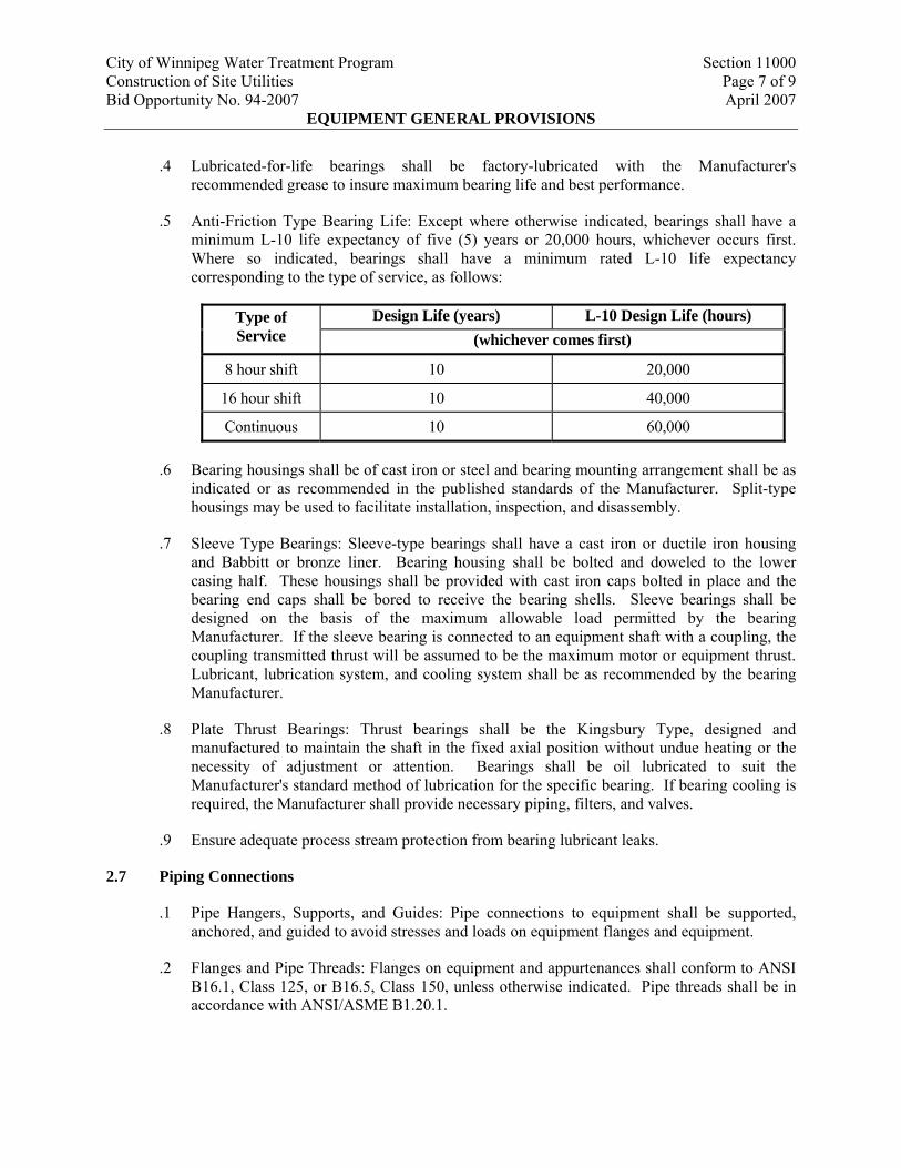
.5 Anti-Friction Type Bearing Life: Except where otherwise indicated, bearings shall have a minimum L-10 life expectancy of five (5) years or 20,000 hours, whichever occurs first. Where so indicated, bearings shall have a minimum rated L-10 life expectancy corresponding to the type of service, as follows:
Design Life (years) L-10 Design Life (hours) Type of Service (whichever comes first)
8 hour shift 10 20,000
16 hour shift 10 40,000
Continuous 10 60,000
.6 Bearing housings shall be of cast iron or steel and bearing mounting arrangement shall be as indicated or as recommended in the published standards of the Manufacturer. Split-type housings may be used to facilitate installation, inspection, and disassembly.
.7 Sleeve Type Bearings: Sleeve-type bearings shall have a cast iron or ductile iron housing and Babbitt or bronze liner. Bearing housing shall be bolted and doweled to the lower casing half. These housings shall be provided with cast iron caps bolted in place and the bearing end caps shall be bored to receive the bearing shells. Sleeve bearings shall be designed on the basis of the maximum allowable load permitted by the bearing Manufacturer. If the sleeve bearing is connected to an equipment shaft with a coupling, the coupling transmitted thrust will be assumed to be the maximum motor or equipment thrust. Lubricant, lubrication system, and cooling system shall be as recommended by the bearing Manufacturer.
.8 Plate Thrust Bearings: Thrust bearings shall be the Kingsbury Type, designed and manufactured to maintain the shaft in the fixed axial position without undue heating or the necessity of adjustment or attention. Bearings shall be oil lubricated to suit the Manufacturer's standard method of lubrication for the specific bearing. If bearing cooling is required, the Manufacturer shall provide necessary piping, filters, and valves.
.9 Ensure adequate process stream protection from bearing lubricant leaks.
2.7 Piping Connections
.1 Pipe Hangers, Supports, and Guides: Pipe connections to equipment shall be supported, anchored, and guided to avoid stresses and loads on equipment flanges and equipment.
.2 Flanges and Pipe Threads: Flanges on equipment and appurtenances shall conform to ANSI B16.1, Class 125, or B16.5, Class 150, unless otherwise indicated. Pipe threads shall be in accordance with ANSI/ASME B1.20.1.
City of Winnipeg Water Treatment Program Section 11000 Construction of Site Utilities Page 8 of 9 Bid Opportunity No. 94-2007 April 2007
EQUIPMENT GENERAL PROVISIONS
.3 Flexible Connectors: Flexible connectors shall be provided in all piping connections to engines, blowers, compressors, and other vibrating equipment and in piping systems. Flexible connectors shall be harnessed or otherwise anchored to prevent separation of the pipe where required by the installation.
.4 Insulating Connections: Insulating bushings, unions, couplings, or flanges, as appropriate, shall be used.
2.8 Gaskets and Packings
.1 Packing around valve stems and reciprocating shafts shall be of compressible material, compatible with the fluid being used. Chevron-type "V" packing shall be Garlock No. 432, John Crane "Everseal".
.2 Packing around rotating shafts (other than valve stems) shall be "O"-rings, stuffing boxes, or mechanical seals, as recommended by the Manufacturer.
2.9 Nameplates
.1 Equipment nameplates of stainless steel shall be engraved or stamped and fastened to the equipment in an accessible location with No. 4 or larger oval head stainless steel screws or drive pins. Nameplates shall contain the Manufacturer's name, model, serial number, size, characteristics, and appropriate data describing the machine performance ratings.
2.10 Tools and Spare Parts
.1 Tools: Furnish one (1) complete set of special wrenches and other special tools necessary for the assembly, adjustment, and dismantling of the equipment. Tools shall be of best quality hardened steel forgings with bright finish. Wrench heads shall have work faces dressed to fit nuts. Tools shall be suitable for professional Work and manufactured by Snap On, Crescent, Stanley, or equal. The set of tools shall be neatly mounted in a labelled toolbox of suitable design provided with a hinged cover.
.2 Spare parts shall be furnished as indicated in the individual equipment Sections. All spare parts shall be suitably packaged in a metal box and labelled with equipment numbers by means of stainless steel or solid plastic nametags attached to the box.
2.11 Equipment Lubricants
.1 Install food grade lubricants for all equipment during storage and prior to initial testing of the equipment.
3. EXECUTION
3.1 Manufacturer's Representative Field Services
.1 Refer to Section 01650 – Equipment Installation.
City of Winnipeg Water Treatment Program Section 11000 Construction of Site Utilities Page 9 of 9 Bid Opportunity No. 94-2007 April 2007
EQUIPMENT GENERAL PROVISIONS
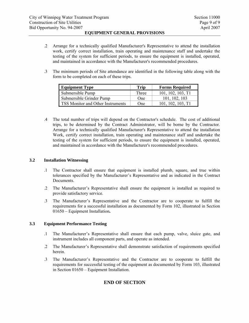
.2 Arrange for a technically qualified Manufacturer's Representative to attend the installation work, certify correct installation, train operating and maintenance staff and undertake the testing of the system for sufficient periods, to ensure the equipment is installed, operated, and maintained in accordance with the Manufacturer's recommended procedures.
.3 The minimum periods of Site attendance are identified in the following table along with the form to be completed on each of these trips.
Equipment Type Trip Forms Required Submersible Pump Three 101, 102, 103, T1 Submersible Grinder Pump One 101, 102, 103 TSS Monitor and Other Instruments One 101, 102, 103, T1
.4 The total number of trips will depend on the Contractor's schedule. The cost of additional trips, to be determined by the Contract Administrator, will be borne by the Contractor. Arrange for a technically qualified Manufacturer's Representative to attend the installation Work, certify correct installation, train operating and maintenance staff and undertake the testing of the system for sufficient periods, to ensure the equipment is installed, operated, and maintained in accordance with the Manufacturer's recommended procedures.
3.2 Installation Witnessing
.1 The Contractor shall ensure that equipment is installed plumb, square, and true within tolerances specified by the Manufacturer’s Representative and as indicated in the Contract Documents.
.2 The Manufacturer’s Representative shall ensure the equipment is installed as required to provide satisfactory service.
.3 The Manufacturer’s Representative and the Contractor are to cooperate to fulfill the requirements for a successful installation as documented by Form 102, illustrated in Section 01650 – Equipment Installation.
3.3 Equipment Performance Testing
.1 The Manufacturer’s Representative shall ensure that each pump, valve, sluice gate, and instrument includes all component parts, and operate as intended.
.2 The Manufacturer’s Representative shall demonstrate satisfaction of requirements specified herein.
.3 The Manufacturer’s Representative and the Contractor are to cooperate to fulfill the requirements for successful testing of the equipment as documented by Form 103, illustrated in Section 01650 – Equipment Installation.
END OF SECTION
City of Winnipeg Water Treatment Program Section 11300 Construction of Site Utilities Page 1 of 8 Bid Opportunity No. 94-2007 April 2007
PROCESS PUMP GENERAL REQUIREMENTS
1. GENERAL
1.1 Description
.1 This Section defines the general requirements for the supply of all pumps required for this Contract.
1.2 Definitions
.1 The terms in the Specification generally comply with the definitions of the Hydraulic Institute.
.2 Definitions:
.1 Pump Bowl Efficiency: Pump efficiency shall be calculated as the pump delivered hydraulic power divided by the mechanical brake horsepower at the inlet shaft of the pump. It shall take full account of mechanical losses. Since this is difficult to measure in the field, it will be calculated based on the Overall Efficiency multiplied by the Electrical Efficiency of the Motor.
.2 Overall Efficiency: Pump and Motor overall efficiency shall be calculated as the pump delivered hydraulic power divided by the electrical power supplied to the motor. It shall take full account of mechanical and electrical losses.
.3 Electrical Efficiency: Motor efficiency shall be calculated as the motor delivered mechanical brake horsepower divided by the electrical power supplied to the motor. It shall take full account of mechanical and electrical losses and will be based on the published guaranteed efficiency of the motor.
.4 Performance Curve: The performance curve is a graph of the flow delivered (L/s; x-axis) in relation to the discharge head (metres; y-axis). It generally denotes efficiencies as isopleths and may include NPSH requirements as a function of the flow.
.5 Best Efficiency Point: The BEP is the point in the pump performance curve where the pump operates at its highest pump efficiency.
.6 Rating Point: The pump rating point is the combination of discharge head and flow which the pump must satisfy. It typically is determined on the basis of all duty pumps (one or more, depending on the service) operating simultaneously against the worst system conditions (typically maximum headloss, minimum suction head, maximum discharge head, etc.). This condition is listed in the detailed pump Specification and must be satisfied by the pump supplied.
.7 Low Head Point: The low head point is the combination of head and flow which corresponds to the least head the pump might operate against. It is determined on the basis of only one (1) duty pump operating against the system conditions which would produce the least discharge pressure (typically minimum headloss, maximum suction
City of Winnipeg Water Treatment Program Section 11300 Construction of Site Utilities Page 2 of 8 Bid Opportunity No. 94-2007 April 2007
PROCESS PUMP GENERAL REQUIREMENTS
head, minimum discharge head, etc.). The minimum system head is shown or described for each pump. The Manufacturer must ensure that the pump can operate satisfactorily, without cavitation in the pump casing or over-stressing of the motor, at the intersection of the pump curve and the minimum head curve, or low head point.
.8 Low Speed Point: The minimum flow and head conditions against which a variable speed pump is expected to operate.
1.3 Submissions
.1 Shop Drawings: Submit in accordance with Sections 01300 – Submittals and 11000 – Equipment General Provisions. For all pump Shop Drawings in addition to the requirements of Section 11000 – Equipment General Provisions, include the following specific details:
.1 Performance curve for the pumping unit(s) superimposed on the system curve for the particular pumping application. With the performance curve, include efficiency isopleths and NPSHR variation with flow. Where required in the specific pump Sections, the performance curve should be certified in accordance with HIS.
.2 Motor operating data, including motor and insulation ratings, start-up and operating current ratings, operating voltage and amperage tolerances, description of construction complete with illustrative Drawings, and any other pertinent information.
.3 List of materials of construction, detailing the component parts of the pump(s), their materials of construction, and reference Specifications for those materials.
.4 Required ancillary services including but not limited to electrical, seal water, and drains. The sizes, ratings, and any other pertinent information related to these services.
.5 Installation instructions indicating assembly and mounting requirements, alignment and assembly tolerances, and points of connection for ancillary services (electrical, seal water, drains, etc.).
.6 Start-up instructions including lubricant requirements, electrical requirements, etc.
.2 O&M Data: Provide for incorporation in the O&M manual as specified in Section 01730 – Operation and Maintenance Manual. Include the following:
.1 Complete description of operation.
.2 General arrangement and detailed Drawings.
.3 Wiring diagrams for power and control schematics.
.4 Parts catalogues with complete list of repair and replacement parts with Section Drawings, illustrating the connections and the part Manufacturer's identifying numbers.
City of Winnipeg Water Treatment Program Section 11300 Construction of Site Utilities Page 3 of 8 Bid Opportunity No. 94-2007 April 2007
PROCESS PUMP GENERAL REQUIREMENTS
1.4 Delivery and Storage
.1 Prior to delivery, ensure that Form 101 the Certificate of Readiness to Install is completed to ensure that the Contractor is ready to receive the specified equipment.
.2 Ship pre-assembled to the degree that is possible.
.3 Securely fasten heavy wood blanks to the pump flanges. Use blanks that are larger diameter than the flange. Protect machined surfaces against rusting. Protect threaded connections with threaded plugs or caps. Protect open, plain pipe ends with caps.
.4 Where pumps are to be stored on Site for any period of time exceeding one (1) week, the Contractor shall be aware of specific requirements to ensure there is no uneven wear or distortion of pump component parts.
.5 Identify any special storage requirements.
1.5 Coordination
.1 Coordinate with other Divisions to ensure there are no conflicts in the Work.
2. PRODUCTS
2.1 Pump Performance Requirements
.1 Supply pumps that are suitable for continuous duty.
.2 Select impellers for fixed speed pumps that permit operation at an efficiency of within 5% of the efficiency at the BEP.
.3 For variable speed pumps, select pump speed and impeller diameter which allow operation from the Rating Point to the Low Speed Point at efficiencies within 10% of efficiency at the BEP.
.4 Ensure that motors are sufficiently sized to drive pumps at a maximum speed when the head is as defined for the low head point.
.5 Supply pumps capable of operating at 30% of the flow at the rated capacity with good efficiency without exceeding the motor horsepower and capable of operating at any point on its characteristic curve, to where that curve intersects the low head point, without exceeding motor power rating.
2.2 Pressure Sensing
.1 For submersible pumps, supply only one (1) gauge for mounting on the discharge of the pump on a weldolet.
City of Winnipeg Water Treatment Program Section 11300 Construction of Site Utilities Page 4 of 8 Bid Opportunity No. 94-2007 April 2007
PROCESS PUMP GENERAL REQUIREMENTS
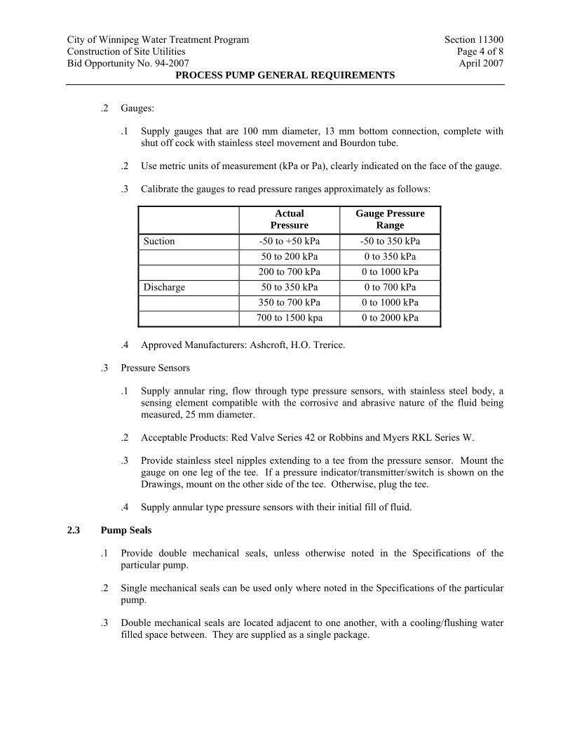
.2 Gauges:
.1 Supply gauges that are 100 mm diameter, 13 mm bottom connection, complete with shut off cock with stainless steel movement and Bourdon tube.
.2 Use metric units of measurement (kPa or Pa), clearly indicated on the face of the gauge.
.3 Calibrate the gauges to read pressure ranges approximately as follows:
Actual Pressure
Gauge Pressure Range
Suction -50 to +50 kPa -50 to 350 kPa 50 to 200 kPa 0 to 350 kPa 200 to 700 kPa 0 to 1000 kPa Discharge 50 to 350 kPa 0 to 700 kPa 350 to 700 kPa 0 to 1000 kPa 700 to 1500 kpa 0 to 2000 kPa
.4 Approved Manufacturers: Ashcroft, H.O. Trerice.
.3 Pressure Sensors
.1 Supply annular ring, flow through type pressure sensors, with stainless steel body, a sensing element compatible with the corrosive and abrasive nature of the fluid being measured, 25 mm diameter.
.2 Acceptable Products: Red Valve Series 42 or Robbins and Myers RKL Series W.
.3 Provide stainless steel nipples extending to a tee from the pressure sensor. Mount the gauge on one leg of the tee. If a pressure indicator/transmitter/switch is shown on the Drawings, mount on the other side of the tee. Otherwise, plug the tee.
.4 Supply annular type pressure sensors with their initial fill of fluid.
2.3 Pump Seals
.1 Provide double mechanical seals, unless otherwise noted in the Specifications of the particular pump.
.2 Single mechanical seals can be used only where noted in the Specifications of the particular pump.
.3 Double mechanical seals are located adjacent to one another, with a cooling/flushing water filled space between. They are supplied as a single package.
City of Winnipeg Water Treatment Program Section 11300 Construction of Site Utilities Page 5 of 8 Bid Opportunity No. 94-2007 April 2007
PROCESS PUMP GENERAL REQUIREMENTS
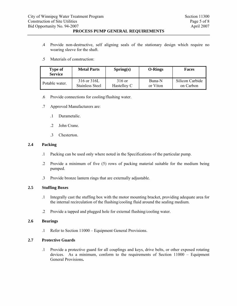
.4 Provide non-destructive, self aligning seals of the stationary design which require no wearing sleeve for the shaft.
.5 Materials of construction:
Type of Service
Metal Parts Spring(s) O-Rings Faces
Potable water. 316 or 316L Stainless Steel
316 or Hastelloy C
Buna-N or Viton
Silicon Carbide on Carbon
.6 Provide connections for cooling/flushing water.
.7 Approved Manufacturers are:
.1 Durametalic.
.2 John Crane.
.3 Chesterton.
2.4 Packing
.1 Packing can be used only where noted in the Specifications of the particular pump.
.2 Provide a minimum of five (5) rows of packing material suitable for the medium being pumped.
.3 Provide bronze lantern rings that are externally adjustable.
2.5 Stuffing Boxes
.1 Integrally cast the stuffing box with the motor mounting bracket, providing adequate area for the internal recirculation of the flushing/cooling fluid around the sealing medium.
.2 Provide a tapped and plugged hole for external flushing/cooling water.
2.6 Bearings
.1 Refer to Section 11000 – Equipment General Provisions.
2.7 Protective Guards
.1 Provide a protective guard for all couplings and keys, drive belts, or other exposed rotating devices. As a minimum, conform to the requirements of Section 11000 – Equipment General Provisions.
City of Winnipeg Water Treatment Program Section 11300 Construction of Site Utilities Page 6 of 8 Bid Opportunity No. 94-2007 April 2007
PROCESS PUMP GENERAL REQUIREMENTS
2.8 Couplings
.1 For all pumps other than submersible and where noted otherwise in the detailed Specifications, provide flexible, double disc spacer type couplings conforming to Section 11000 – Equipment General Provisions.
.2 Design couplings so that the pump unit can be disassembled without disturbing face piping.
2.9 Shafts
.1 Design shafts to absorb 1.15 times the rated power of the motors required to drive the pumps when the pump is fitted with maximum size impellers.
2.10 V-Belt Drives
.1 Do not use V-belt drives unless specified or shown on the Drawings.
.2 Conform to the requirements of Section 11000 – Equipment General Provisions.
.3 Where V-belt drives are indicated, ensure that the pump motor can handle operating speeds 20% higher than required for the specified operating points.
2.11 Tagging Instructions
.1 Tag loose items associated with a particular unit with the equipment number. Use aluminum or stainless steel (no plastic) tags securely attached to each item.
.2 Identification used shall be the same as the symbol indicated in the Specifications or on the Drawings and shall be located in a conspicuous place as acceptable to the Contract Administrator.
2.12 Spare Parts
.1 For each pump, provide for one (1) spare mechanical seal or packing kit (as applicable) and one (1) set of pump bearings.
.2 For each centrifugal pump type and size, provide a single impeller, wear plate, suction ring (if replaceable), one (1) pump shaft and nut.
.3 For spare parts for positive displacement pumps, provide as a minimum, one (1) wearing element. Refer to related pump Specifications for the specific spare part requirements.
2.13 Factory Performance Testing
.1 Where required for specific pumps, as noted in the Sections related to those pumps, factory performance test all pumps.
.2 Conduct factory performance testing in compliance with the HIS.
City of Winnipeg Water Treatment Program Section 11300 Construction of Site Utilities Page 7 of 8 Bid Opportunity No. 94-2007 April 2007
PROCESS PUMP GENERAL REQUIREMENTS
.3 Inform Contract Administrator at least three (3) weeks prior to the factory testing to allow for his attendance.
.4 Certify test results and summarize findings in a short report. Submit report to the Contract Administrator within three (3) weeks of completing factory tests.
.5 Where the pump(s) does not satisfy the specified performance requirements within the tolerances specified by the Hydraulics Institute, redesign, modify, and re-test the pump(s), all at no additional cost.
.6 Do not ship the pump(s) until the test result report has been submitted to the Contract Administrator.
2.14 Finishes
.1 Factory prime all pumps in accordance with Section 11901 – Factory Applied Maintenance and Corrosion Protection Coatings.
3. EXECUTION
3.1 General
.1 Comply with the requirements of the specific Sections for the pumps to be provided.
3.2 Installation
.1 Comply with the requirements of Section 01650 – Equipment Installation and any special requirements listed in the specific Sections related to each pump.
3.3 Testing
.1 The Contractor will field test all pumps greater than or equal to 3.7 kW, and smaller units where noted, to verify performance. The Contractor will record the results of the testing and provide as required, clarification of testing procedures, or any additional information necessary to complete testing in an appropriate manner.
.2 The Contractor will provide temporary connections, flow monitoring, pressure monitoring, ammeters, and temporary tankage required for the performance of the tests.
.3 Flow Metering:
.1 Where possible, use fill and draw techniques to determine the amount of flow conveyed during the test period. Ensure that the volumes are sufficient for at least five (5) minutes of pump operation at the flows that are to be tested, other than runout.
.2 Where permanent flow meters are installed on the downstream piping, they may be used to measure the flow during testing when accepted by the Contract Administrator.
City of Winnipeg Water Treatment Program Section 11300 Construction of Site Utilities Page 8 of 8 Bid Opportunity No. 94-2007 April 2007
PROCESS PUMP GENERAL REQUIREMENTS
Ensure that the permanent flow meters are calibrated to within 5% of the rated flow of the pump to be tested prior to testing.
.3 Temporary metering may be used if accepted by the Contract Administrator. Temporary meters must have an accuracy of plus or minus 5%, at the rated flow of the pump, to be acceptable.
.4 Where other methods are not possible or where directed, use dye testing to determine the flow during the test periods. Dye testing is to be conducted by an agency acceptable to the Contract Administrator. Measured flows during the testing will be certified by a qualified Representative of the Contract Administrator to be within 5% of the actual flows.
.4 Pressure Monitoring:
.1 Do not use permanent gauges for pressure monitoring during tests. Temporary test gauges can be connected to the permanent gauge taps.
.2 Use gauges with sufficient accuracy to measure anticipated pressures on pump discharges within 2.5%. Where pump suction draws from an open tank or wet well, test gauge must be capable of measuring pressure at pump suction within 1.0 kPa.
.3 Provide evidence of pressure gauge calibration within three (3) months of conducting tests.
.5 Test pump(s) at a minimum of three (3) flow conditions, typically corresponding to the rating point flow, 75% of that flow, and 120% of that flow. At each test point, measure flow, pressure, and amperage. In addition, verify run-out conditions.
.6 For variable speed pumps, conduct the tests at two (2) speeds, typically 100% of the design speed and 30% of the design speed.
.7 Field Test Report:
.1 Compile field test results into a report for submittal to the Contract Administrator.
.2 Describe test set-up and measurement devices used to conduct the tests.
.3 For each pump, list the specified performance requirements and field test results. Show field test results (flow, pressure, power draw) superimposed on the performance curve provided with the submissions.
.8 Where field tests do not verify compliance with specified performance requirements; investigate cause for noncompliance, undertake remedial Work as required to bring pump into compliance or replace the pump and all necessary ancillaries, and retest to prove compliance. All Work required to bring the pump into compliance is the responsibility of the Contractor and will be performed at no extra cost to the City.
END OF SECTION
City of Winnipeg Water Treatment Program Section 11305 Construction of Site Utilities Page 1 of 9 Bid Opportunity No. 94-2007 April 2007
PROCESS SUBMERSIBLE PUMPS
1. GENERAL
1.1 Scope of Work
.1 The Work under this Section includes supply, delivery, installation, training, testing, and performance verification support for submersible pumps, the package control panel, and other ancillary items for a complete working pump station.
1.2 References
.1 The following is a list of standards that may be referenced in this Section:
.1 ASTM:
.1 A48, Standard Specification for Gray Iron Castings.
.2 A576, Standard Specification for Steel Bars, Carbon, Hot-Wrought, Special Quality.
.2 HIS
.3 Canadian Electrical Code, CSA C22.1
.4 NEMA
.5 ULC
1.3 Definitions
.1 Terminology pertaining to pumping unit performance and construction shall conform to ratings and nomenclature of HIS.
1.4 Submittals
.1 Shop Drawings, Refer to Section 01300 – Submittals:
.1 Make, model, weight, and horsepower of each equipment assembly.
.2 Complete catalogue information, descriptive literature, specifications, dimensions, and identification of materials of construction.
.3 Performance data curves showing head, capacity, horsepower demand, and pump efficiency over entire operating range of pump, from shutoff to maximum capacity. Indicate separately design points, head, capacity, horsepower demand, overall efficiency, and minimum submergence required at guarantee point.
.4 Power and control wiring diagrams, including terminals and numbers.
City of Winnipeg Water Treatment Program Section 11305 Construction of Site Utilities Page 2 of 9 Bid Opportunity No. 94-2007 April 2007
PROCESS SUBMERSIBLE PUMPS
.5 Complete motor nameplate data, as defined by NEMA, from motor manufacturer.
.6 Factory finish system.
.7 Bearing life calculations.
.2 Quality Control Submittals:
.1 Factory and Field Performance Test Reports and Log.
.2 Manufacturer's Certification of Compliance that factory finish system meets requirements specified herein.
.3 Special shipping, storage and protection, and handling instructions.
.4 Manufacturer's printed installation instructions.
.5 Manufacturer's Certificate of Proper Installation.
.6 Suggested spare parts list to maintain equipment in service for period of one (1) year and five (5) years. Include list of special tools required for checking, testing, parts replacement, and maintenance with current price information.
.7 List special tools, materials, and supplies furnished with equipment for use prior to and during start-up and for future maintenance.
.8 O&M manual.
1.5 Extra Materials
.1 Furnish for each size of pumps:
.1 One (1) set mechanical seals.
.2 One (1) complete set of special tools required to dismantle pump.
2. PRODUCTS
2.1 Supplements
.1 Pump datasheet and any other specific requirements are attached to this Section as supplements.
2.2 Components
.1 Pump equipment shall consist of pump(s) complete with motor(s), control system, guide rail and anchoring brackets, base elbow, power cable(s), and pump lifting cable(s).
.1 Pump metal parts that come into contact with guide rail or cable system shall be made of non-sparking materials.
City of Winnipeg Water Treatment Program Section 11305 Construction of Site Utilities Page 3 of 9 Bid Opportunity No. 94-2007 April 2007
PROCESS SUBMERSIBLE PUMPS
.2 Control panel and level switches and level transmitters.
.2 Lifting Arrangement: 2500 mm minimum, stainless steel chain, and one “grip-eye.” Attach chain permanently to pump and access platform with stainless steel wire rope. “Grip-eye” will be capable of being threaded over and engaging links of stainless steel chain so pump and motor may be lifted with “grip-eye” and independent hoist.
.3 Sliding guide bracket shall be integral part of pump unit. Pump unit shall be guided by no less than two (2) guide bars, or equivalent cable system, and pressed tightly against discharge connection elbow with metal-to-metal contact or through use of profile-type gasket, provided that gasket is attached to pump’s flange and can be easily accessed for inspection when pump is lifted out of wet well.
.4 Oil chamber between seals shall be equipped with drain and inspection plug. Plug shall have positive anti-leak seal and shall be easily accessible from outside. Provide leak detection output signal to control panel.
.5 Motor nameplate horsepower shall not be exceeded at any head-capacity point on pump curve.
.6 Pump motor and sensor cables shall be suitable for submersible pump application and cable sizing shall conform to Canadian Electrical Code specifications for pump motors. Cable shall be of sufficient length to reach junction boxes without strain or splicing.
.7 Cable Entry System:
.1 Junction chamber and motor shall be separated by stator lead sealing gland or terminal board that shall prevent foreign material entering through pump top.
.2 Utilize cable with factory-installed sealing gland with non-shrink epoxy seal system.
.3 O-ring compression seal between sealing gland and cable entry point shall also be acceptable.
2.3 Control Panel
.1 NEMA 12 painted steel enclosure, for outdoor duty. Refer to Divisions 16 and 17, Instruments & Panels Subsystem, for additional panel requirements.
.2 Free standing, wall mounted.
.3 Control panel shall include:
.1 Main circuit breaker disconnect interlocked with panel door.
.2 Combination circuit breaker type, NEMA rated motor starters.
.3 Fused control power transformer, 120 VAC.
City of Winnipeg Water Treatment Program Section 11305 Construction of Site Utilities Page 4 of 9 Bid Opportunity No. 94-2007 April 2007
PROCESS SUBMERSIBLE PUMPS
.4 Duty alternator and duty/standby controls.
.5 ON/OFF/CPU switches.
.6 Running lights.
.7 High level indication.
.8 Normally closed, dry, 5 A at 120 VAC contacts for future remote indication of:
.1 High level alarm.
.2 Pump failure (temperature or moisture alarm).
.9 Terminal strip for interfacing with external wiring.
.10 High temperature indication.
.11 Moisture alarm indication.
.12 Alarm (high temperature, moisture, or high level) beacon located on top of panel.
.13 Lightning protection.
.14 Alarm silence button.
.15 Document pocket located inside panel with pump and panel O&M manual and separate laminated pump curve.
.16 110 V, duplex GFI outlet, weather-protected, and accessible from outside of panel.
.17 Run hour meter.
.18 100 W minimum, condensation heater with thermostat.
.19 ULC labelled panel.
.4 Pre-wired and factory tested.
.5 Mount control switches, indicating lights, and switches on hinged front panel.
.6 Single Feed: 575 V, 3 phase.
2.4 Accessories
.1 Level Switch/Transmitters:
.1 Provide level switch and level transmitters as shown on Drawings for:
.1 Low low level - alarm.
.2 Low level – pump off. (from level transmitter)
City of Winnipeg Water Treatment Program Section 11305 Construction of Site Utilities Page 5 of 9 Bid Opportunity No. 94-2007 April 2007
PROCESS SUBMERSIBLE PUMPS
.3 High level – pump on. (from level transmitter)
.4 High high level – alarm.
.2 In accordance with Divisions 16 and 17, Instruments and Panel Subsystems components.
.2 Provide input points for 4 to 20 mA signals from the TSS monitor and flow meter.
.3 Interface to WTP control system MODBUS RS232 connection to Ethernet converter.
.4 Equipment Identification Plate: 16 gauge stainless steel with 6 mm die-stamped equipment tag number securely mounted in readily visible location.
.5 Lifting Lugs: Equipment weighing over 45 kg.
.6 Anchor Bolts: Type 316 stainless steel, sized by equipment manufacturer.
2.5 Factory Finishing
.1 Prepare, prime, and finish coat in accordance with Section 11900 – Field Applied Corrosion Protection and Maintenance Coatings, and Section 11901 – Factory Applied Maintenance and Corrosion Protection Coatings.
2.6 Source Quality Control
.1 Control Panel:
.1 Factory Inspections: Inspect control panels for required construction, electrical connection, and intended function.
.2 Factory Tests and Adjustments: Test all control panels furnished.
.2 Pump:
.1 Factory Performance Test:
.1 In accordance with HIS 1.6, for centrifugal pump tests.
.2 Include test data sheets, curve test results, performance test logs.
.2 Conduct on each pump.
.3 Perform under actual or approved simulated operating conditions:
.1 Throttle discharge valve to obtain pump data points on curve at 2/3, 1/3, and shutoff conditions.
City of Winnipeg Water Treatment Program Section 11305 Construction of Site Utilities Page 6 of 9 Bid Opportunity No. 94-2007 April 2007
PROCESS SUBMERSIBLE PUMPS
.3 Motor Functional Test: Perform Manufacturer's standard motor test. Submerge and run for thirty (30) minutes at pumping conditions corresponding to maximum motor load.
3. EXECUTION
3.1 Installation by Contractor
.1 Installation will be in accordance with the Manufacturer’s printed installation instructions. Installation includes but is not limited to:
.1 Connect suction and discharge piping without imposing strain to pump flanges.
.2 No portion of pump shall bear directly on floor of sump.
3.2 Field Finishing
.1 No field coating is allowed only field touch up in accordance with the Manufacturer’s recommendation is permitted.
3.3 Field Quality Control by Contractor
.1 Functional Tests: Conduct on each pump.
.1 Alignment: Test complete assemblies for correct rotation, proper alignment and connection, and quiet operation.
.2 Vibration Test:
.1 Test with units installed and in normal operation, and discharging to the connected piping systems at rates between the low discharge head and high discharge head conditions specified, and with the actual building structures and foundations provided shall not develop at any frequency or in any plane, peak-to-peak vibration amplitudes in excess of 0.1 mm or velocities in excess of 3 mm/sec.
.2 If units exhibit vibration in excess of the limits specified adjust or modify as necessary. Units that cannot be adjusted or modified to conform as specified shall be replaced.
.3 Flow Output: Measured by local instrumentation and storage volumes.
.4 Operating Temperatures: Monitor bearing areas on pump and motor for abnormally high temperatures.
.2 Performance Test: In accordance with HIS and/or more stringent requirements as described herein for operating conditions indicated in supplemental equipment data sheets.
City of Winnipeg Water Treatment Program Section 11305 Construction of Site Utilities Page 7 of 9 Bid Opportunity No. 94-2007 April 2007
PROCESS SUBMERSIBLE PUMPS
3.4 Manufacturer's Representative Field Services
.1 Verify satisfactory delivery of the equipment by completing Form 100, illustrated in Section 01650 – Equipment Installation.
.2 Instruct Contractor in the methods and precautions to be followed in the installation of the equipment. Certify the Contractor's understanding by completing Form 101, illustrated in Section 01650 – Equipment Installation.
.3 Arrange for a technically qualified Manufacturer's Representative to attend the installation work, certify correct installation, train operating and maintenance staff and undertake the testing of the system for sufficient periods, to ensure the equipment is installed, operated, and maintained in accordance with the Manufacturer's recommended procedures.
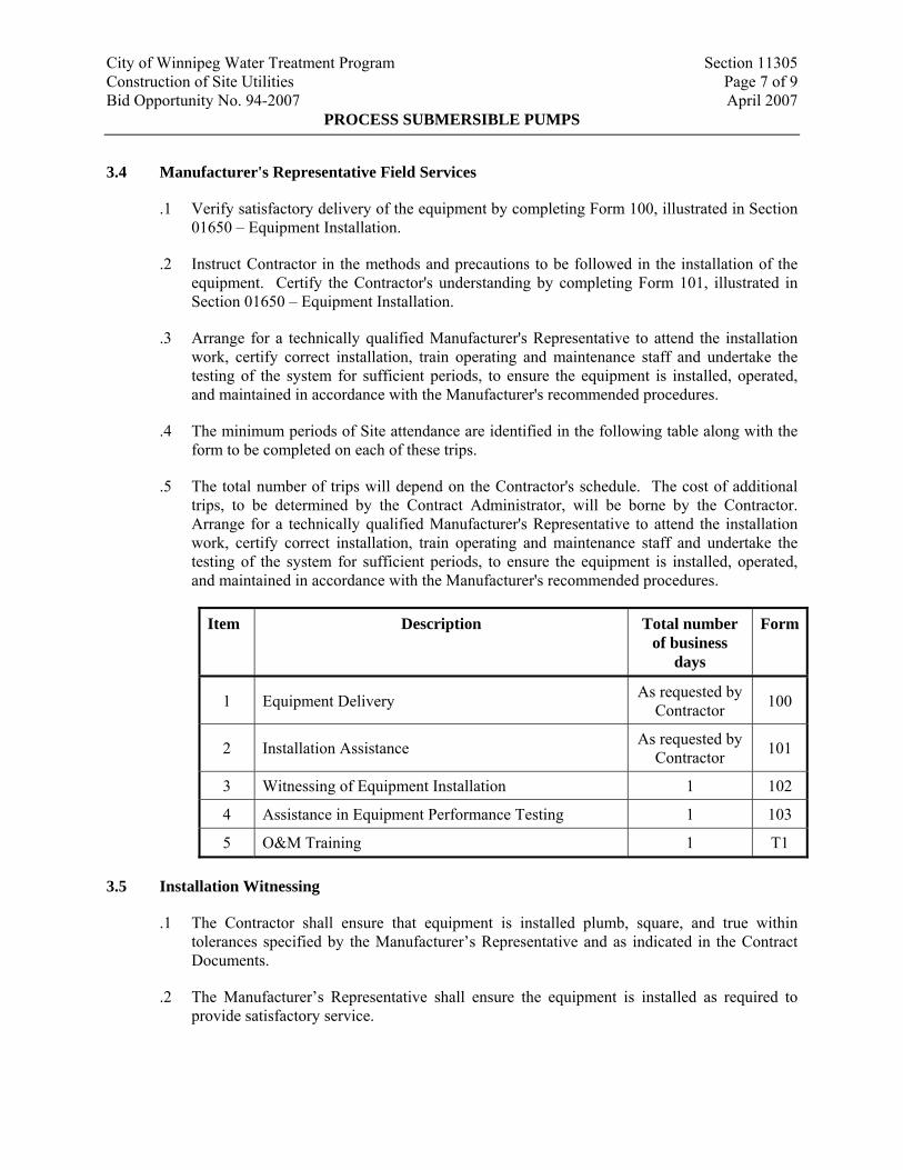
.4 The minimum periods of Site attendance are identified in the following table along with the form to be completed on each of these trips.
.5 The total number of trips will depend on the Contractor's schedule. The cost of additional trips, to be determined by the Contract Administrator, will be borne by the Contractor. Arrange for a technically qualified Manufacturer's Representative to attend the installation work, certify correct installation, train operating and maintenance staff and undertake the testing of the system for sufficient periods, to ensure the equipment is installed, operated, and maintained in accordance with the Manufacturer's recommended procedures.
Item Description Total number of business
days
Form
1 Equipment Delivery As requested by Contractor 100
2 Installation Assistance As requested by Contractor 101
3 Witnessing of Equipment Installation 1 102
4 Assistance in Equipment Performance Testing 1 103
5 O&M Training 1 T1
3.5 Installation Witnessing
.1 The Contractor shall ensure that equipment is installed plumb, square, and true within tolerances specified by the Manufacturer’s Representative and as indicated in the Contract Documents.
.2 The Manufacturer’s Representative shall ensure the equipment is installed as required to provide satisfactory service.
City of Winnipeg Water Treatment Program Section 11305 Construction of Site Utilities Page 8 of 9 Bid Opportunity No. 94-2007 April 2007
PROCESS SUBMERSIBLE PUMPS
.3 The Manufacturer’s Representative and the Contractor are to cooperate to fulfill the requirements for a successful installation as documented by Form 102, illustrated in Section 01650 – Equipment Installation.
3.6 Equipment Performance Testing
.1 The Manufacturer’s Representative shall ensure that each pump, including all component parts, operates as intended.
.2 The Manufacturer’s Representative shall demonstrate satisfaction of requirements specified herein.
.3 The Manufacturer’s Representative and the Installation Contractor are to cooperate to fulfill the requirements for successful testing of the equipment as documented by Form 103, illustrated in Section 01650 – Equipment Installation.
3.7 Training
.1 The Manufacturer’s Representative shall provide the services of factory trained instructors for the purpose of training the City’s personnel in the proper operation and maintenance of the equipment as documented by Form T1. Conform to the requirements of Section 01650 – Equipment Installation.
3.8 Supplements
.1 Data Sheets:
.1 Dewatering Pumps: P-L921, P-L922.
City of Winnipeg Water Treatment Program Section 11305 Construction of Site Utilities Page 9 of 9 Bid Opportunity No. 94-2007 April 2007
PROCESS SUBMERSIBLE PUMPS
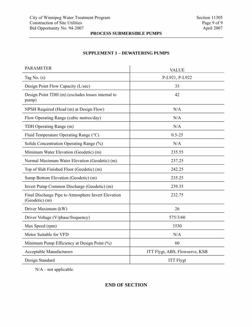
SUPPLEMENT 1 – DEWATERING PUMPS
PARAMETER VALUE
Tag No. (s) P-L921, P-L922
Design Point Flow Capacity (L/sec) 35
Design Point TDH (m) (excludes losses internal to pump)
42
NPSH Required (Head (m) at Design Flow) N/A
Flow Operating Range (cubic metres/day) N/A
TDH Operating Range (m) N/A
Fluid Temperature Operating Range (°C) 0.5-25
Solids Concentration Operating Range (%) N/A
Minimum Water Elevation (Geodetic) (m) 235.55
Normal Maximum Water Elevation (Geodetic) (m) 237.25
Top of Slab Finished Floor (Geodetic) (m) 242.25
Sump Bottom Elevation (Geodetic) (m) 235.25
Invert Pump Common Discharge (Geodetic) (m) 239.35
Final Discharge Pipe to Atmosphere Invert Elevation (Geodetic) (m)
232.75
Driver Maximum (kW) 26
Driver Voltage (V/phase/frequency) 575/3/60
Max Speed (rpm) 3530
Motor Suitable for VFD N/A
Minimum Pump Efficiency at Design Point (%) 60
Acceptable Manufacturers ITT Flygt, ABS, Flowserve, KSB
Design Standard ITT Flygt
N/A – not applicable.
END OF SECTION
City of Winnipeg Water Treatment Program Section 11391 Construction of Site Utilities Page 1 of 14 Bid Opportunity No. 94-2007 April 2007
PACKAGED SEWAGE LIFT STATION, WET WELL TYPE
1. GENERAL
1.1 Scope of Work
.1 The Work under this Section includes supply, delivery, installation, training, testing, and performance verification support for semi-positive displacement submersible grinder pump system, the package control panel, tankage connection to existing sanitary system and other ancillary items for a complete working pump station.
1.2 References
.1 Section 02315 – Excavation, Trenching and Backfilling
.2 The following is a list of standards that may be referenced in this Section:
.1 HIS
.2 Canadian Electrical Code, CSA C22.1
.3 NEMA
.4 ULC
1.3 Definitions
.1 Terminology pertaining to pumping unit performance and construction shall conform to ratings and nomenclature of HIS.
1.4 Submittals
.1 Shop Drawings, Refer to Section 01300 – Submittals:
.1 Make, model, weight, and horsepower of each equipment assembly.
.2 Complete catalogue information, descriptive literature, specifications, dimensions, and identification of materials of construction.
.3 Performance data curves showing head, capacity, horsepower demand, and pump efficiency over entire operating range of pump, from shutoff to maximum capacity. Indicate separately design points, head, capacity, horsepower demand, overall efficiency, and minimum submergence required at guarantee point.
.4 Power and control wiring diagrams, including terminals and numbers.
.5 Complete motor nameplate data, as defined by NEMA, from motor manufacturer.
.6 Factory finish system.
.7 Bearing life calculations.
City of Winnipeg Water Treatment Program Section 11391 Construction of Site Utilities Page 2 of 14 Bid Opportunity No. 94-2007 April 2007
PACKAGED SEWAGE LIFT STATION, WET WELL TYPE
.2 Quality Control Submittals:
.1 Manufacturer’s warranty performance certificate: minimum twenty four (24) months.
.2 Factory and Field Performance Test Reports and Log.
.3 Manufacturer's Certification of Compliance that factory finish system meets requirements specified herein.
.4 Special shipping, storage and protection, and handling instructions.
.5 Manufacturer's printed installation instructions.
.6 Manufacturer's Certificate of Proper Installation.
.7 Suggested spare parts list to maintain equipment in service for period of one (1) year and five (5) years. Include list of special tools required for checking, testing, parts replacement, and maintenance with current price information.
.8 List special tools, materials, and supplies furnished with equipment for use prior to and during start-up and for future maintenance.
.9 O&M manual.
.3 Other:
.1 Excavation plan for the existing sanitary storage tank.
.2 Condition inspection of existing sanitary tank, including tank material, dimensional drawings of all components, and any other observations related to the construction.
.3 Details of the anti-flotation concrete anchor, sealed by a Professional Engineer registered to APEGM.
.4 Details of the connections to the existing sanitary FRP tank, sealed by a Professional Engineer registered to APEGM.
.5 Safe work plan.
1.5 Extra Materials
.1 Supply one (1) spare grinder pump core, complete with all operational controls, level sensors, check valve, anti-siphon valve, pump/motor unit, and grinder.
1.6 Measurement and Payment
.1 Packaged sewage lift station shall be measured as a lump sum basis. The lump sum price shall be payment in full for all working and materials specified herein required for a
City of Winnipeg Water Treatment Program Section 11391 Construction of Site Utilities Page 3 of 14 Bid Opportunity No. 94-2007 April 2007
PACKAGED SEWAGE LIFT STATION, WET WELL TYPE
complete and operational sewage lift station, and the supply and installation of electrical and control service from the pump control panel to the Deacon Booster Pump Station.
2. PRODUCTS
2.1 Operating Conditions
.1 The pumps shall be capable of delivering 0.94 L/s against a rated total dynamic head of 0 m and 0.57 L/s against a rated total dynamic head of 42 m. The pump(s) must also be capable of operating at negative total dynamic head without overloading the motor(s).
2.2 Supplements
.1 Pump datasheet and any other specific requirements are attached to this Section as supplements.
2.3 Components
.1 Pump: the pump shall be a custom designed, integral, vertical rotor, motor driven, solids handling pump of the progressing cavity type with a single mechanical seal. The rotor shall be through-hardened, highly polished, precipitation hardened stainless steel. The stator shall be of a specifically compounded ethylene propylene synthetic elastomer.
.2 Grinder: the grinder shall be placed immediately below the pumping elements and shall be direct-driven by a single, one-piece motor shaft. The grinder impeller assembly shall be securely fastened to the pump motor shaft by means of a threaded connection attaching the grinder impeller to the motor shaft. Attachment by means of pins or keys will not be acceptable. The grinder will be of the rotating type with a stationary hardened and ground stainless steel shredding ring spaced in close annular alignment with the driven impeller assembly, which shall carry two hardened type 400 series stainless steel cutter bars.
.1 This assembly shall be dynamically balanced and operate without objectionable noise or vibration over the entire range of recommended operating pressures. The grinder shall be constructed so as to eliminate clogging and jamming under all normal operating conditions including starting. Sufficient vortex action shall be created to scour the tank free of deposits or sludge banks which would impair the operation of the pump. These requirements shall be accomplished by the following, in conjunction with the pump:
.1 The grinder shall be positioned in such a way that solids are fed in an upward flow direction.
.2 The maximum flow rate through the cutting mechanism must not exceed 1.2 m/s. This is a critical design element to prevent jamming and as such must be adhered to.
.3 The inlet shroud shall have a diameter of no less than 125 mm.
City of Winnipeg Water Treatment Program Section 11391 Construction of Site Utilities Page 4 of 14 Bid Opportunity No. 94-2007 April 2007
PACKAGED SEWAGE LIFT STATION, WET WELL TYPE
.4 The impeller mechanism must rotate at a nominal speed of no greater than 1800 rpm.
.2 The grinder shall be capable of reducing all components in normal domestic sewage, including a reasonable amount of “foreign objects,” such as paper, wood, plastic, glass, rubber and the like, to finely-divided particles which will pass freely through the passages of the pump and the 32 mm diameter discharge.
.3 Electrical motor: the motor shall be a 0.75 kW, 1725 rpm, 120 V 60 Hertz, 1 Phase, capacitor start, ball bearing, air-cooled induction type with a low starting current not to exceed 30 amperes and high starting torque of 11.4 N. m. Inherent protection against running overloads or locked rotor conditions for the pump motor shall be provided by the use of an automatic-reset, integral thermal overload protector incorporated into the motor. This motor protector combination shall have been specifically investigated and listed by Underwriters Laboratories, Inc., for the application. Non-capacitor start motors or permanent split capacitor motors will not be accepted because of their reduced starting torque and consequent diminished grinding capability. To reduce the potential of environmental concerns, the expense of handling and disposing of oil, and the associated maintenance costs, oil-filled motors will not be accepted.
.4 Mechanical seal: the pump/core shall be provided with a mechanical shaft seal to prevent leakage between the motor and pump. The seal shall have a stationary ceramic seat and carbon rotating surface with faces precision lapped and held in position by a stainless steel spring.
.5 Discharge hose and slide face disconnect/valve: all discharge fittings and piping shall be constructed of 304 series stainless steel, polypropylene, EPDM or PVC. The discharge hose assembly shall include a shut-off valve rated for 1380 kPa WOG and a quick disconnect feature to simplify installation and pump removal.
.6 Electrical quick disconnect: the grinder pump unit shall include a single NEMA 6P electrical quick disconnect for all power and control functions. An integral tube shall allow venting of the control compartment to assure proper operation of the pressure switch level system. The grinder pump will be furnished with a length of 6 conductor, 14 gauge, type SJOW cable, pre-wired and watertight to meet UL requirements.
.7 Check valve: the pump discharge shall be equipped with a factory-installed, gravity-operated, flapper-type integral check valve built into the pump discharge. The check valve will provide a full-ported passageway when open, and shall introduce a friction loss of less than 6 inches of water at maximum rated flow. Moving parts will be made of a 300 series stainless steel and fabric-reinforced synthetic elastomer to ensure corrosion resistance, dimensional stability, and fatigue strength. A nonmetallic hinge shall be an integral part of the flapper assembly providing a maximum degree of freedom to assure seating even at a very low back pressure. The valve body shall be an injection molded part made of glass filled PVC. Ball-type check valves are unacceptable due to their limited sealing capacity in slurry applications.
City of Winnipeg Water Treatment Program Section 11391 Construction of Site Utilities Page 5 of 14 Bid Opportunity No. 94-2007 April 2007
PACKAGED SEWAGE LIFT STATION, WET WELL TYPE
.8 Anti-siphon valve: the pump discharge shall be equipped with a factory-installed, gravity-operated, flapper-type integral anti-siphon valve built into the stainless steel discharge piping. Moving parts will be made of 300 series stainless steel and fabric-reinforced synthetic elastomer to ensure corrosion resistance, dimensional stability, and fatigue strength. A nonmetallic hinge shall be an integral part of the flapper assembly, providing a maximum degree of freedom to ensure proper operation even at a very low pressure. The valve body shall be injection-molded from a glass-filled thermoplastic resin. Holes or ports in the discharge piping are not acceptable anti-siphon devices, due to their tendency to clog from the solids in the slurry being pumped.
.9 The grinder pump station shall have an easily removable core assembly containing pump, motor, grinder, all motor controls, check valve, anti-siphon valve, electrical quick disconnect and wiring. The watertight integrity of the core unit, shall be established by 100% factory test at a minimum of 34.5 kPa.
.10 The grinder pump core unit shall have two lifting hooks complete with polypropylene lift-out harness connected to its top housing to facilitate easy core removal when necessary. All mechanical and electrical connections must provide easy disconnect capability for core unit removal and installation. A push to run feature will be provided for field trouble shooting. All motor control components shall be mounted on a readily replaceable bracket for ease of field service.
.11 Motor nameplate horsepower shall not be exceeded at any head-capacity point on pump curve.
.12 Pump motor and sensor cables shall be suitable for submersible pump application and cable sizing shall conform to Canadian Electrical Code specifications for pump motors. Cable shall be of sufficient length to reach junction boxes without strain or splicing.
.13 Tank and Integral Accessway:
.1 Fibreglass-Reinforced Polyester Resin: The tank shall be custom moulded of fibreglass reinforced polyester resin. Tank wall and bottom must withstand the pressure exerted by saturated soil loading at maximum burial depth. All station components must function normally when exposed to 150 percent maximum external soil and hydrostatic pressure.
.2 The accessway shall be an integral extension of the wet well assembly and include a lockable cover assembly providing low profile mounting and watertight capability. Accessway design and construction shall facilitate field adjustment of station height in increments of 75 mm without the use of any adhesives or sealants requiring cure time before installation can be completed.
.3 The station shall have all necessary penetrations moulded in and factory sealed. To ensure a leak-free installation, no field penetrations shall be acceptable.
.4 All discharge piping shall be constructed of 304 Series Stainless Steel and terminate outside the accessway bulkhead with a stainless steel, 32 mm female NPT fitting. The
City of Winnipeg Water Treatment Program Section 11391 Construction of Site Utilities Page 6 of 14 Bid Opportunity No. 94-2007 April 2007
PACKAGED SEWAGE LIFT STATION, WET WELL TYPE
discharge piping shall include a stainless steel ball valve rated for 1380 kPa WOG; PVC ball valve will not be accepted. The bulkhead penetration shall be factory installed and warranted by the manufacturer to be watertight.
.5 The accessway shall include a single NEMA 6P electrical quick disconnect (EQD) for all power and control functions, factory installed with accessway penetrations warranted by the manufacturer to be watertight. Plug-type connections of the power cable onto the pump housing will not be acceptable due to the potential for leaks and electrical shorts. The accessway shall also include a 50 mm PVC vent to prevent sewage gases from accumulating in the tank.
.14 Control Panel:
.1 All necessary controls, including motor and level controls, shall be located in the top housing of the core unit. The top housing will be attached with stainless steel fasteners.
.2 Non-fouling waste water level controls for controlling pump operation shall be accomplished by monitoring the pressure changes in an integral air column connected to a pressure switch. The level detection device shall have no moving parts in direct contact with the wastewater. High-level sensing will be accomplished in the manner detailed above by a separate air-bell sensor and pressure switch of the same type. Closure of the high-level sensing device will energize an alarm circuit as well as a redundant pump-on circuit. For increased reliability, pump ON/OFF and High-level alarm functions shall not be controlled by the same switch. Float switches of any kind, including float trees, will not be accepted due to the periodic need to maintain (rinsing, cleaning) such devices.
.3 To assure reliable operation of the differential pressure switches each core shall be equipped with a pressure equalization chamber. The equalization chamber shall continuously calibrate the level sensing pressure switches to fluctuations in barometric pressure and prevent fluid from entering the control compartment during high water level conditions. The equalization chamber shall be constructed from EPDM, High Impact Polystyrene and stainless steel and measure 300 mm in diameter by 150 mm high. The chamber shall be assembled by the core manufacturer and factory tested at the point of assembly to verify proper operation.
.4 The grinder pump will be furnished with 6 conductor 14 gauge, type SJOW cable, pre-wired and watertight to meet UL requirements with a factory installed NEMA 6P EQD half attached to it.
.5 Control panel shall include:
.1 Main circuit breaker disconnect interlocked with panel door.
.2 Combination circuit breaker type, NEMA rated motor starters.
.3 Fused control power transformer, 120 VAC.
City of Winnipeg Water Treatment Program Section 11391 Construction of Site Utilities Page 7 of 14 Bid Opportunity No. 94-2007 April 2007
PACKAGED SEWAGE LIFT STATION, WET WELL TYPE
.4 ON/OFF/CPU switches.
.5 Running lights.
.6 High level indication.
.7 Normally closed, dry, 5 A at 120 VAC contacts for future remote indication of:
.1 High level alarm.
.2 Pump failure (temperature or moisture alarm).
.8 Terminal strip for interfacing with external wiring.
.9 High temperature indication.
.10 Moisture alarm indication.
.11 Alarm (high temperature, moisture, or high level) beacon located on top of panel.
.12 Lightning protection.
.13 Alarm silence button.
.14 Document pocket located inside panel with pump and panel operation and maintenance manual and separate laminated pump curve.
.15 110 V, duplex GFI outlet, weather-protected, and accessible from outside of panel.
.16 Run hour meter.
.17 100 W minimum, condensation heater with thermostat.
.18 ULC labelled panel.
.6 Prewired and factory tested.
.7 Mount control switches, indicating lights, and switches on hinged front panel.
.8 Single feed: 120 V, 1 phase.
.15 Alarm panel: each grinder pump station shall include a NEMA 4X, UL-listed Alarm Panel suitable for wall or pole mounting. The NEMA 4X enclosure shall be manufactured of thermoplastic polyester to ensure corrosion resistance. The enclosure shall include a hinged, lockable cover with padlock, preventing access to electrical components, and creating a secured safety front to allow access only to authorized personnel. The enclosure shall not exceed 267 W x 355 H x 178 D (mm), or 318 W x 356 H x 190 D (mm) if certain options are included.
City of Winnipeg Water Treatment Program Section 11391 Construction of Site Utilities Page 8 of 14 Bid Opportunity No. 94-2007 April 2007
PACKAGED SEWAGE LIFT STATION, WET WELL TYPE
.1 The alarm panel shall contain one (1) 15-amp, double-pole circuit breaker for the pump core’s power circuit and one (1) 15-amp single-pole circuit breaker for the alarm circuit. The panel shall contain a push-to-run feature, an internal run indicator, and a complete alarm circuit. All circuit boards in the Alarm Panel are to be protected with a conformal coating and the AC power circuit shall include an auto resetting fuse.
.2 The alarm panel shall include the following features: external audible and visual alarm; push-to-run switch; and redundant pump start with high level alarm capability. The alarm sequence is to be as follows:
.1 When liquid level in the sewage wet well rises above the alarm level, audible and visual alarms are activated, the contacts on the alarm pressure switch close, and the redundant pump starting system is energized.
.2 The audible alarm may be silenced by means of the externally mounted, push-to-silence button.
.3 Visual alarm remains illuminated until the sewage level in the wet well drops below the “off” setting of the alarm pressure switch.
.3 The visual alarm lamp shall be inside a red, oblong lens at least 95 L x 60 W x 38 H (mm). Visual alarm shall be mounted to the top of the enclosure in such a manner as to maintain NEMA 4X rating. The audible alarm shall be externally mounted on the bottom of the enclosure, capable of 93 dB @ 0.6 m. The audible alarm shall be capable of being deactivated by depressing a push-type switch that is encapsulated in a weatherproof silicone boot and mounted on the bottom of the enclosure (push-to-silence button).
.4 The entire alarm panel, as manufactured and including any of the following options shall be listed by Underwriters Laboratories, Inc.
.5 All materials exposed to waste water shall have inherent corrosion protection.
.16 NEMA 12 painted steel enclosure, for outdoor duty. Refer to Divisions 16 and 17, Instruments and Panels Subsystem, for additional panel requirements.
2.4 Accessories
.1 Provide level control devices for:
.1 Low level – pump off. (from level transmitter)
.2 High level – pump on. (from level transmitter)
.3 High high level – alarm.
.2 In accordance with Divisions 16 and 17, Instruments and Panel Subsystems components.
City of Winnipeg Water Treatment Program Section 11391 Construction of Site Utilities Page 9 of 14 Bid Opportunity No. 94-2007 April 2007
PACKAGED SEWAGE LIFT STATION, WET WELL TYPE
.3 Interface to WTP control system MODBUS RS232 connection to Ethernet converter.
.4 Equipment Identification Plate: 16 gauge stainless steel with 6 mm die-stamped equipment tag number securely mounted in readily visible location.
2.5 Source Quality Control
.1 Control Panel:
.1 Factory Inspections: Inspect control panels for required construction, electrical connection, and intended function.
.2 Factory Tests and Adjustments: Test all control panels furnished.
.2 Pump:
.1 Factory Performance Test:
.1 In accordance with HIS 1.6, for centrifugal pump tests.
.2 Include test data sheets, curve test results, performance test logs.
.2 Conduct on each pump.
.3 Perform under actual or approved simulated operating conditions.
.1 Throttle discharge valve to obtain pump data points on curve at 2/3, 1/3, and shutoff conditions.
.3 Motor Functional Test: Perform Manufacturer's standard motor test. Submerge and run for thirty (30) minutes at pumping conditions corresponding to maximum motor load.
3. EXECUTION
3.1 Factory Test:
.1 Each grinder pump shall be submerged and operated for 5 minutes (minimum). Included in this procedure will be the testing of all ancillary components such as, the anti-siphon valve, check valve, discharge assembly and each unit’s dedicated level and motor controls. All factory tests shall incorporate each of the above listed items. Actual appurtenances and controls which will be installed in the field, shall be particular to the tested pump only. A common set of appurtenances and controls for all pumps will not be acceptable. Certified test results shall be available upon request showing the operation of each grinder pump at two (2) different points on its curve, with the maximum pressure no less than 414 kPa. The Contract Administrator reserves the right to inspect such testing procedures with representatives of the City, at the grinder pump manufacturer’s facility.
City of Winnipeg Water Treatment Program Section 11391 Construction of Site Utilities Page 10 of 14 Bid Opportunity No. 94-2007 April 2007
PACKAGED SEWAGE LIFT STATION, WET WELL TYPE
3.2 Delivery:
.1 All Grinder Pump units will be delivered to the job site, 100% completely assembled, including testing, ready for installation.
3.3 Installation:
.1 The electrical enclosure shall be furnished, installed and wired to the grinder pump station by the Contractor. An alarm device is required on every installation.
.2 The Contractor shall mount the alarm device in a conspicuous location, as per national and local codes. The Alarm Panel will be connected to the Grinder Pump Station by a length of six (6) conductor 12 gauge TC type cable as shown on the contract drawings. The power and alarm circuits must be on separate power circuits. The grinder pump station will be provided with a minimum of 9.75 m of useable electrical supply cable outside the station, to connect to the alarm panel. This cable shall be provided with a factory installed EQD half to connect to the mating EQD half on the core.
.3 The Contractor shall be responsible for handling ground water to provide a firm, dry subgrade for the structure, and shall guard against flotation or other damage resulting from general water or flooding.
.4 The grinder pump station shall not be set into the excavation until the installation procedures and excavation have been approved by the Contract Administrator.
.5 Installation shall be accomplished so that 25 mm to 100 mm of accessway, below the bottom of the lid, extends above the finished grade line. The finished grade shall slope away from the unit. The diameter of the excavated hole must be large enough to allow for the concrete anchor.
.6 A 150 mm (minimum) layer of naturally rounded aggregate, clean and free flowing, with particle size of not less than 3 mm or more than 20 mm shall be used as bedding material under each unit.
.7 A concrete anti-flotation collar, and sized according to the Manufacturer’s instructions, shall be required and shall be pre-cast to the grinder pump or poured in place. Each grinder pump station with its pre-cast anti-flotation collar shall have a minimum of three (3) lifting eyes for loading and unloading purposes.
.8 If the concrete is poured in place, the unit shall be levelled, and filled with water, to the bottom of the inlet, to help prevent the unit from shifting while the concrete is being poured. The concrete must be manually vibrated to ensure there are no voids. If it is necessary to pour the concrete to a level higher than the inlet piping, a 200 mm sleeve is required over the inlet prior to the concrete being poured.
.9 Make connections to existing piping and tank as shown on the drawings.
City of Winnipeg Water Treatment Program Section 11391 Construction of Site Utilities Page 11 of 14 Bid Opportunity No. 94-2007 April 2007
PACKAGED SEWAGE LIFT STATION, WET WELL TYPE
3.4 Backfill Requirements:
.1 Backfill to 200 mm above the highest pipe connection with sand confirming to CW2030.
.2 Backfill the remaining excavation with Class 2 backfill as specified in CW2030.
.3 All restoration shall be the responsibility of the Contractor. The site shall be restored to its original condition, in all respects, including, but not limited to, curb and sidewalk replacement, landscaping, top soiling and seeding, and restoration of traveling ways, as directed by the Contractor Administrator.
3.5 Start-up and Field Testing:
.1 The Manufacturer shall provide the services of qualified factory trained technician(s) who shall inspect the placement and wiring of each station, perform field tests as specified herein, and instruct the City’s personnel in the operation and maintenance of the equipment before the stations are accepted by the City.
.2 All equipment and materials necessary to perform testing shall be the responsibility of the Contractor.
.3 The services of a trained factory-authorized technician shall be provided at a rate of 2 days. Each day shall be ten (10) person hours in duration.
.4 Upon completion of the installation, the authorized factory technicians will perform the following test on each station:
.1 Make certain the discharge shut-off valve is fully open. Turn ON the alarm power circuit.
.2 Fill the wet well with water to a depth sufficient to verify the high level alarm is operating. Shut off water.
.3 Turn ON pump power circuit. Initiate pump operation to verify automatic “on/off” controls are operative. Pump should immediately turn ON. Within one (1) minute alarm light will turn OFF. Within three (3) minutes the pump will turn OFF.
.5 Upon completion of the start-up and testing, the manufacturer shall submit to the Contract Administrator the start-up authorization form describing the results of the tests performed for each Grinder Pump Station. Final acceptance of the system will not occur until authorization forms have been received for each pump station installed and any installation deficiencies corrected.
3.6 Field Finishing
.1 No field coating is allowed. Only field touch-up in accordance with the Manufacturer’s recommendation is permitted.
City of Winnipeg Water Treatment Program Section 11391 Construction of Site Utilities Page 12 of 14 Bid Opportunity No. 94-2007 April 2007
PACKAGED SEWAGE LIFT STATION, WET WELL TYPE
3.7 Field Quality Control by Contractor
.1 Functional Tests: Conduct on each pump.
.1 Alignment: Test complete assemblies for correct rotation, proper alignment and connection, and quiet operation.
.2 Vibration Test:
.1 Test with units installed and in normal operation, and discharging to the connected piping systems at rates between the low discharge head and high discharge head conditions specified, and with the actual building structures and foundations provided shall not develop at any frequency or in any plane, peak-to-peak vibration amplitudes in excess of 0.1 mm or velocities in excess of 3 mm/sec.
.2 If units exhibit vibration in excess of the limits specified adjust or modify as necessary. Units that cannot be adjusted or modified to conform as specified shall be replaced.
.3 Flow Output: Measured by local instrumentation and storage volumes.
.4 Operating Temperatures: Monitor bearing areas on pump and motor for abnormally high temperatures.
.2 Performance Test: In accordance with HIS and/or more stringent requirements as described herein for operating conditions indicated in supplemental equipment data sheets.
3.8 Manufacturer's Representative Field Services
.1 Verify satisfactory delivery of the equipment by completing Form 100, illustrated in Section 01650 – Equipment Installation.
.2 Instruct Contractor in the methods and precautions to be followed in the installation of the equipment. Certify the Contractor's understanding by completing Form 101, illustrated in Section 01650 – Equipment Installation.
.3 Arrange for a technically qualified Manufacturer's Representative to attend the installation work, certify correct installation, and undertake the testing of the system for sufficient periods, to ensure the equipment is installed, operated, and maintained in accordance with the Manufacturer's recommended procedures.
.4 The minimum periods of Site attendance are identified in the following table along with the form to be completed on each of these trips.
.5 The total number of trips will depend on the Contractor's schedule. The cost of additional trips, to be determined by the Contract Administrator, will be borne by the Contractor. Arrange for a technically qualified Manufacturer's Representative to attend the installation work, certify correct installation, and undertake the testing of the system for sufficient
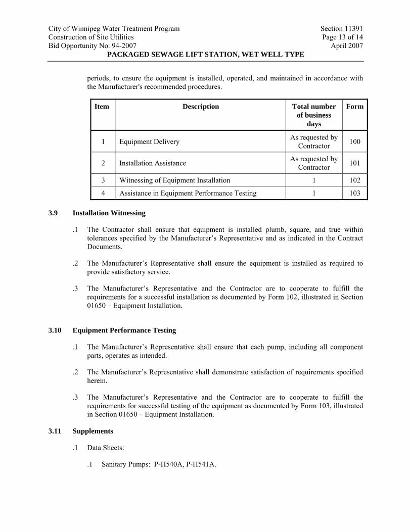
City of Winnipeg Water Treatment Program Section 11391 Construction of Site Utilities Page 13 of 14 Bid Opportunity No. 94-2007 April 2007
PACKAGED SEWAGE LIFT STATION, WET WELL TYPE
periods, to ensure the equipment is installed, operated, and maintained in accordance with the Manufacturer's recommended procedures.
Item Description Total number of business
days
Form
1 Equipment Delivery As requested by Contractor 100
2 Installation Assistance As requested by Contractor 101
3 Witnessing of Equipment Installation 1 102
4 Assistance in Equipment Performance Testing 1 103
3.9 Installation Witnessing
.1 The Contractor shall ensure that equipment is installed plumb, square, and true within tolerances specified by the Manufacturer’s Representative and as indicated in the Contract Documents.
.2 The Manufacturer’s Representative shall ensure the equipment is installed as required to provide satisfactory service.
.3 The Manufacturer’s Representative and the Contractor are to cooperate to fulfill the requirements for a successful installation as documented by Form 102, illustrated in Section 01650 – Equipment Installation.
3.10 Equipment Performance Testing
.1 The Manufacturer’s Representative shall ensure that each pump, including all component parts, operates as intended.
.2 The Manufacturer’s Representative shall demonstrate satisfaction of requirements specified herein.
.3 The Manufacturer’s Representative and the Contractor are to cooperate to fulfill the requirements for successful testing of the equipment as documented by Form 103, illustrated in Section 01650 – Equipment Installation.
3.11 Supplements
.1 Data Sheets:
.1 Sanitary Pumps: P-H540A, P-H541A.
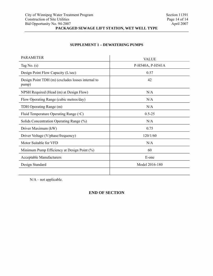
City of Winnipeg Water Treatment Program Section 11391 Construction of Site Utilities Page 14 of 14 Bid Opportunity No. 94-2007 April 2007
PACKAGED SEWAGE LIFT STATION, WET WELL TYPE
SUPPLEMENT 1 – DEWATERING PUMPS
PARAMETER VALUE
Tag No. (s) P-H540A, P-H541A
Design Point Flow Capacity (L/sec) 0.57
Design Point TDH (m) (excludes losses internal to pump)
42
NPSH Required (Head (m) at Design Flow) N/A
Flow Operating Range (cubic metres/day) N/A
TDH Operating Range (m) N/A
Fluid Temperature Operating Range (◦C) 0.5-25
Solids Concentration Operating Range (%) N/A
Driver Maximum (kW) 0.75
Driver Voltage (V/phase/frequency) 120/1/60
Motor Suitable for VFD N/A
Minimum Pump Efficiency at Design Point (%) 60
Acceptable Manufacturers E-one
Design Standard Model 2016-180
N/A – not applicable.
END OF SECTION
City of Winnipeg Water Treatment Program Section 11900 Construction of Site Utilities Page 1 of 5 Bid Opportunity No. 94-2007 April 2007
FIELD-APPLIED CORROSION PROTECTION AND MAINTENANCE COATINGS
1. GENERAL
.1 Provide, apply, and maintain the specified field applied protective and maintenance coating systems. Coatings are required on all process and mechanical equipment, vessels, and pipes unless specifically deleted.
.2 Refer to Drawings and Schedules for the type, location, and extent of coatings required and include for all field coating necessary to complete all the work shown, specified, or scheduled.
1.2 Delivery and Storage
.1 Deliver all coating materials to the Site in sealed containers properly labelled to indicate the Manufacturer's name, type and colour of contents, date of manufacture, batch number, and storage requirements.
.2 Provide adequately heated and ventilated storage for all materials and ensure compliance with fire prevention regulations.
2. PRODUCTS
2.1 Manufacturers
.1 All constituents of each coating system are to be provided by the same Manufacturer.
.2 Acceptable Manufacturers: Valspar, Sherwin Williams, Benjamin Moore
2.2 Schedule of Surface Treatments
.1 The Schedule of Surface Treatments defines the components of the protective coating system.
City of Winnipeg Water Treatment Program Section 11900 Construction of Site Utilities Page 2 of 5 Bid Opportunity No. 94-2007 April 2007
FIELD-APPLIED CORROSION PROTECTION AND MAINTENANCE COATINGS
Schedule of Surface Treatments
Ref. Description Surface Treatments A Solvent Cleaning As SSPC-SP1 B Hand Tool Cleaning As SSPC-SP2 C Power Tool Cleaning As SSPC-SP3 D Brush Blast As SSPC-SP7 E Near White Metal Blast As SSPC-SP10 F White Metal Blast As SSPC-SP5 (NACE #1) G Abrasion The surface shall be lightly abraded using steel wool or
abrasive cloth to provide a key for the next coat, to remove runs or excessive brush marks.
H Vinyl Wash Primer DFT 13 microns. To be over-coated within 24 hours I Zinc Chromate Primer Nominal DFT 40 microns J Inorganic Zinc Primer Zinc in ethyl silicate vehicle. Minimum DFT 40 microns K Industrial Enamel
(to 100ºC) To 1-GP-61M Alkyd Enamel. Minimum DFT 30 microns
L High Built Epoxy To AWWA C210 and certified by an appropriate testing agency (NSF Std. 61, CSA, etc.) for use on waste water applications. Minimum DFT 200 microns
M Bituminous Paint To AWWA C230, MIL-P-151470 N Silicone Alkyd
(100ºC to 150ºC) Min. 60% solids by weight. Nominal DFT 40 microns
O Silicone Enamel (150ºC to 400ºC)
To 1-GP-143M, DFT 40 microns
P Fast Drying Aluminum Sealer
To 1-GP-69M, Nominal DFT 25 microns
Q Canvas Insulation Sealer Acrylic or PVA latex R Epoxy Gloss Enamel To 1-GP-146, nominal DFT 50 microns
SSPC: Steel Structures Painting Council, 4400 Fifth Avenue, Pittsburgh, PA 15213 Surface Preparation Specifications, March 1985.
2.3 Schedule of Protective Systems
.1 The schedule of protective systems defines the combination of surface treatments required in each system and the sections of the plant to which it is to be applied. The systems have been grouped into three (3) categories as follows:
.1 Category A: Immersed Service, equipment or material fully, partially or intermittently immersed in water during routine plant operation.
City of Winnipeg Water Treatment Program Section 11900 Construction of Site Utilities Page 3 of 5 Bid Opportunity No. 94-2007 April 2007
FIELD-APPLIED CORROSION PROTECTION AND MAINTENANCE COATINGS
.2 Category B: Exposed Service, equipment or material exposed to the normal range of atmospheric conditions and conditions common to water treatment facilities (high humidity, etc.)
.3 Category C: Indoor Service, equipment or materials inside buildings or other ventilated spaces.
2.4 Category A
.1 Category A: All Category A systems will be tested by the Contract Administrator using a wet sponge holiday detector set at 67.5 V. Touch-up will be required at points where the detector is grounded.
.2 Schedule:
Schedule of Systems
System Surface Treatments Typical Applications
A1 A, D, L, L Equipment or piping delivered with inorganic zinc primer, e.g. clarifier mechanics, mixers, etc.
A2 A, F, J, L, L Equipment or piping delivered uncoated or with coatings not compatible with epoxy, e.g. ductile iron, cast iron or steel pipe and pipe sleeves inside treatment units. External Surfaces at valves, fabricated pipe supports, brackets, etc.
A3 A, G, M Aluminum surfaces in contact with concrete, e.g. access cover frames A4 A, E Ferrous metal surface cast into concrete, e.g. penstocks, pipe sleeves A5 A Stainless steels, plastics, and fibreglass products
2.5 Category B
.1 Schedule:
Schedule of Systems
System Surface Treatments Typical Applications B1 A, B, R, R Equipment or piping delivered with inorganic zinc primer, e.g.
motors, flocculator gearbox & motor, valve headstocks, piping above ground & outside treatment units, hydrants, etc.
B2 A, B, J, R, R Equipment or piping delivered but not applied with an inorganic zinc prime coat or with a prime coat not compatible with an inorganic zinc overcoat.
B3 A, B, H, R, R Galvanized or cadmium plated goods, e.g. pipe supports or brackets, mountings for electrical or control equipment (Unistrut, etc.)
B4 A Stainless steel or aluminum products, e.g. insulation recovering
City of Winnipeg Water Treatment Program Section 11900 Construction of Site Utilities Page 4 of 5 Bid Opportunity No. 94-2007 April 2007
FIELD-APPLIED CORROSION PROTECTION AND MAINTENANCE COATINGS
2.6 Category C
.1 Schedule
Schedule of Systems
System Surface Treatments Typical Applications
C1 A, B, K, K Equipment or piping delivered c/w factory finished coatings. Coated for system identification and maintenance. Surface temperature during operation not exceeding 100ºC, e.g. pumps, air handling units, valves, etc.
C2 A, G, K, K Equipment or accessories fully primed. Surface temperatures not exceeding 100ºC, e.g. pumps, steel piping
C3 A, C, I, N, N Equipment or accessories as C1 or C2 but with operating surface temperatures between 100ºC and 150ºC, e.g. air compressors, blowers
C4 E, J, O Equipment or accessories as C1 or C2 but with operating surface temperatures between 150ºC and 400ºC, e.g. boiler fittings
C5 B, P, K, K Piping or valves with bituminous or tar coatings. Surface temperatures not exceeding 100ºC, e.g. cast iron & ductile iron pipe, valves.
C6 A, K, K PVC pipe, fittings or accessories coated for identification only. C7 A, H, K, K Aluminum insulation recovering coated for identification only. C8 A, Q, G, N, N
Canvas insulation recovering.
NOTE: (1) Surface preparation G-abrasion has not been fully scheduled but is to be carried out between all coatings.
(2) No bare ferrous metal surfaces are permitted. Pipe hanger rods etc., unless zinc or cadmium plated, are to be at least prime coated. Cut ends of plated surfaces (Uni-strut, etc.) are to be spot primed.
2.7 Colour Coding
.1 Coordinate with the Contract Administrator for pipe and equipment identification colour coding.
3. EXECUTION
3.1 Quality Assurance
.1 Apply all paints and coatings strictly in accordance with the Manufacturer's directions.
City of Winnipeg Water Treatment Program Section 11900 Construction of Site Utilities Page 5 of 5 Bid Opportunity No. 94-2007 April 2007
FIELD-APPLIED CORROSION PROTECTION AND MAINTENANCE COATINGS
.2 Pay particular attention to ensure the compatibility of each surface treatment with the preceding and subsequent surface treatments and coatings. Ensure the compatibility of all surface treatments and coatings.
3.2 Environmental Conditions
.1 Do not apply a coating when the ambient or surface temperature is below 10°C or less than 3°C above the dew point.
.2 Provide adequate ventilation and sufficient heating to maintain temperatures above 7°C for twenty four (24) hours before coatings are applied. Continue heating to maintain 10ºC during application and for forty eight (48) hours after application.
.3 Provide a minimum of 300 lux illumination on surface to be treated.
.4 Do not apply coatings where dust is being generated.
3.3 Protection
.1 Provide sufficient drop cloths, shields and protective equipment to prevent spray or droppings from fouling surfaces not being painted. Make good any damage resulting from inadequate or unsuitable protection.
.2 Maintain all coated surfaces until completion of the works. Damage to coatings, occurring at any time, shall be made good within seven (7) days.
.3 Place cotton waste, cloths, and material which may constitute a fire hazard in closed metal containers and remove from the Site at suitable intervals.
.4 Remove and, after painting, replace or adequately mask all grease nipples, bright metal surfaces, identification plates and other items not to be painted. Do not use solvent that may remove permanent lacquer finishes.
3.4 Condition of Surfaces
.1 Thoroughly examine all surfaces to be treated or coated prior to commencement of Work. Report, in writing, to the Contract Administrator any condition or defect that may affect the integrity or quality of the finished coating. Do not commence Work on any section until all such defects in that section have been corrected.
.2 On all factory primed or coated equipment, touch-up defects prior to the application of subsequent coatings.
.3 Be responsible for the condition of surfaces and for correcting defects and deficiencies in the surface.
END OF SECTION
City of Winnipeg Water Treatment Program Section 11901 Construciton of Site Utilities Page 1 of 5 Bid Opportunity No. 94-2007 April 2007
FACTORY APPLIED MAINTENANCE AND CORROSION PROTECTION COATINGS
1. GENERAL
1.1 Work Included
.1 Supply and application of all factory applied prime coats or factory applied finish coats.
1.2 Submissions
.1 With the equipment Shop Drawings, submit details of the coating systems to be applied.
1.3 Quality Assurance
.1 This Specification is intended to be a minimum reference standard. The Contractor may submit for review alternative coating systems for specific items of equipment which provide equal or better corrosion protection and maintenance service than those specified herein.
2. PRODUCTS
2.1 Surface Preparation
.1 Immersion Service: After degreasing, dry blast all ferrous components to a white metal finish in accordance with SSPC-SP5 to a degree of cleanliness in accordance with NACE No. 1 and obtain a 50 µm blast profile.
.2 Non-immersion Service: After degreasing, dry blast all ferrous components to a near white finish in accordance with SSPC-SP10 to a degree of cleanness in accordance with NACE No. 3 and obtain a 50 µm blast profile.
2.2 Prime Coating
.1 Prime coat all ferrous surfaces before the blasted surfaces deteriorate.
.2 Coat ferrous surfaces with inorganic zinc primer, containing a minimum of 50% solids by volume, applied to a minimum dry film thickness of 75 µm.
.3 Coating method shall be governed by the coating Manufacturer’s recommendation and to the requirement of SSPC 6000 Painting Practices.
2.3 Assembly
.1 For items which are to be bolted together before shipment, clean surfaces and coat before the parts are assembled.
.2 Continuous weld all welded connections, sealing the mating surface completely. On completion of the welding and fettling, treat all weld seams with phosphoric acid solution. Rinse and thoroughly dry before the prime is applied.
.3 Where dissimilar metals are mated insulate the mating surfaces from one another to provide protection against corrosion. Insulate bolts, nuts, washers, and rivets in a similar manner.
City of Winnipeg Water Treatment Program Section 11901 Construciton of Site Utilities Page 2 of 5 Bid Opportunity No. 94-2007 April 2007
FACTORY APPLIED MAINTENANCE AND CORROSION PROTECTION COATINGS
.4 Use 304 stainless steel or better for all nuts, bolts, washers and similar fittings for immersion service. For non-immersion service, use 304 stainless or zinc or cadmium plated nuts, bolts, washers, and similar fittings. Clean and coat the inner face of non-threaded bolt holes as required for other surfaces.
2.4 Schedule of Surface Treatments
.1 The schedule of Surface Treatments defines the components of the protective coating systems.
Schedule of Surface Treatments
Ref. Description Surface Treatments A Solvent Cleaning As SSPC-SP1 B Hand Tool Cleaning As SSPC-SP2 C Power Tool Cleaning As SSPC-SP3 D Brush Blast As SSPC-SP7 E Near White Metal Blast As SSPC-SP10 F White Metal Blast As SSPC-SP5 (NACE #1) G Abrasion The surface shall be lightly abraded using steel wool or
abrasive cloth to provide a key for the next coat, to remove runs or excessive brush marks.
H Vinyl Wash Primer DFT 13 µ. To be over-coated within 24 hours I Water Borne Acrylic Primer Nominal DFT 40 µ J Inorganic Zinc Primer Zinc in ethyl silicate vehicle. Minimum DFT 40 µ K Industrial Enamel (to 100ºC) To CGSB 1-GP-61M Alkyd Enamel. Minimum DFT 30 µ L High Built Epoxy To AWWA C210, certified by appropriate testing agency
(NSF STD 61-CSA, etc.). For use on potable water application.
M Bituminous Paint To AWWA C230, MIL-P-151470 N Silicone Alkyd (100ºC to 150ºC) Min. 60% solids by weight. O Silicone Enamel (150ºC to
400ºC) To CGSB 1-GP-143M, DFT 40 µ
P Fast Drying Aluminum Sealer To CTSB 1-GP-69M, Nominal DFT 25 µ Q Canvas Insulation Sealer Acrylic or PVA latex R Epoxy Gloss Enamel To CGSB 1-GP-146. Nominal DFT 50 µ SSPC: Steel Structures Painting Council, 4400 Fifth Avenue, Pittsburgh, PA 15213
Surface Preparation Specifications, March 1985.
City of Winnipeg Water Treatment Program Section 11901 Construciton of Site Utilities Page 3 of 5 Bid Opportunity No. 94-2007 April 2007
FACTORY APPLIED MAINTENANCE AND CORROSION PROTECTION COATINGS
2.5 Schedule of Protective Systems
.1 The schedule of protective systems defines the combination of surface treatments required in each system and the sections of the plant to which it is to be applied. The systems have been grouped into three categories as follows:
.1 Category A: Immersed Service - equipment or material fully, partially or intermittently immersed in water (chlorinated) during routine plant operation.
.2 Category B: Exposed Service - equipment or material exposed to the normal range of atmospheric conditions and conditions common to water treatment and storage (high humidity, etc.)
.3 Category C: Indoor Service - equipment or material inside buildings or other ventilated spaces.
2.6 Category A
.1 Category A: All category A systems will be tested by the Contract Administrator using a wet sponge holiday detector set at 67.5 V. Touch up will be required at points where the detector is grounded.
.2 Schedule:
Schedule of Systems
System Surface Treatments Typical Applications
A1 A, D, L, L Equipment or piping delivered with inorganic zinc primer A2 A, F, J, L, L Equipment or piping delivered uncoated or with coatings not
compatible with epoxy, e.g. ductile iron, cast iron or steel pipe and pipe sleeves inside treatment units. External Surfaces at valves, fabricated pipe supports, brackets, etc.
A3 A, G, M Aluminum surfaces in contact with concrete, e.g. access cover frames A4 A, E Ferrous metal surface cast into concrete, e.g. penstocks, pipe sleeves A5 A Stainless steels, plastics, and fibreglass products A6 A,E,J,M,M Ferrous metal immersed in abrasive environment
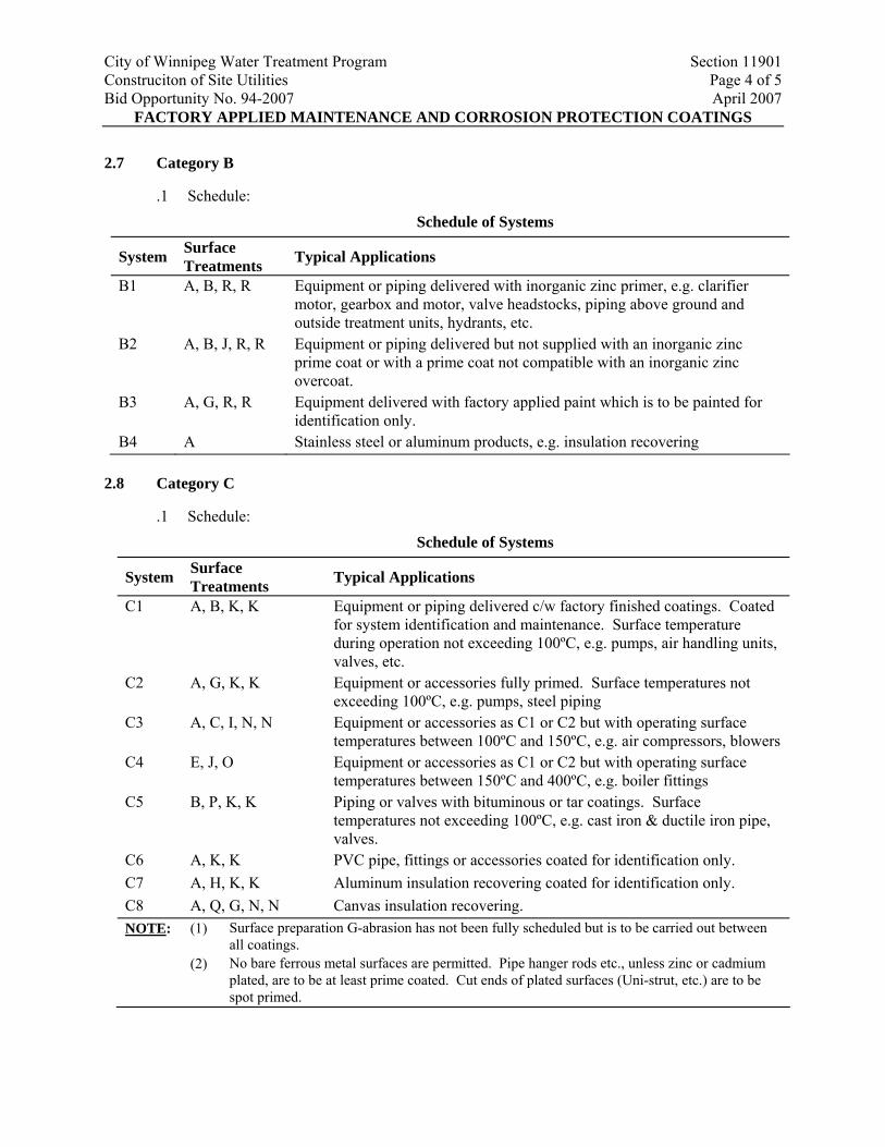
City of Winnipeg Water Treatment Program Section 11901 Construciton of Site Utilities Page 4 of 5 Bid Opportunity No. 94-2007 April 2007
FACTORY APPLIED MAINTENANCE AND CORROSION PROTECTION COATINGS
2.7 Category B
.1 Schedule: Schedule of Systems
System Surface Treatments Typical Applications
B1 A, B, R, R Equipment or piping delivered with inorganic zinc primer, e.g. clarifier motor, gearbox and motor, valve headstocks, piping above ground and outside treatment units, hydrants, etc.
B2 A, B, J, R, R Equipment or piping delivered but not supplied with an inorganic zinc prime coat or with a prime coat not compatible with an inorganic zinc overcoat.
B3 A, G, R, R Equipment delivered with factory applied paint which is to be painted for identification only.
B4 A Stainless steel or aluminum products, e.g. insulation recovering 2.8 Category C
.1 Schedule: Schedule of Systems
System Surface Treatments Typical Applications
C1 A, B, K, K Equipment or piping delivered c/w factory finished coatings. Coated for system identification and maintenance. Surface temperature during operation not exceeding 100ºC, e.g. pumps, air handling units, valves, etc.
C2 A, G, K, K Equipment or accessories fully primed. Surface temperatures not exceeding 100ºC, e.g. pumps, steel piping
C3 A, C, I, N, N Equipment or accessories as C1 or C2 but with operating surface temperatures between 100ºC and 150ºC, e.g. air compressors, blowers
C4 E, J, O Equipment or accessories as C1 or C2 but with operating surface temperatures between 150ºC and 400ºC, e.g. boiler fittings
C5 B, P, K, K Piping or valves with bituminous or tar coatings. Surface temperatures not exceeding 100ºC, e.g. cast iron & ductile iron pipe, valves.
C6 A, K, K PVC pipe, fittings or accessories coated for identification only. C7 A, H, K, K Aluminum insulation recovering coated for identification only. C8 A, Q, G, N, N Canvas insulation recovering. NOTE: (1) Surface preparation G-abrasion has not been fully scheduled but is to be carried out between
all coatings. (2) No bare ferrous metal surfaces are permitted. Pipe hanger rods etc., unless zinc or cadmium
plated, are to be at least prime coated. Cut ends of plated surfaces (Uni-strut, etc.) are to be spot primed.
City of Winnipeg Water Treatment Program Section 11901 Construciton of Site Utilities Page 5 of 5 Bid Opportunity No. 94-2007 April 2007
FACTORY APPLIED MAINTENANCE AND CORROSION PROTECTION COATINGS
2.9 Colour Coding
.1 Refer to Section 11910 – Identification for pipe and equipment identification colour coding.
2.10 Acceptable Products
.1 General Paints Canada Ltd.
.2 ICI Paints Canada Ltd.
.3 Amercoat Ltd.
.4 Rust Oleum
.5 Valspar
.6 Carboline
.7 Plasite
3. EXECUTION
3.1 Inspection
.1 Notify the Contract Administrator two (2) weeks before commencing the protective coating to permit the inspection by the Contract Administrator of the surface preparation and protective coating application.
3.2 Protection
.1 Protect all coated equipment adequately against damage, dust, moisture, and scratching during shipment, off-loading and storage on Site. If, in the opinion of the Contract Administrator, the coating is damaged during shipment to the extent that touch-up would not be satisfactory, return and re-coat the equipment at the Contractor's cost.
.2 Make good damage to coatings occurring at any time prior to the application of any further coatings.
3.3 Application Conditions
.1 Apply all factory applied coatings under controlled conditions, in a dust-free atmosphere at a temperature of between 10 and 20°C, and a relative humidity should not exceed 80%.
END OF SECTION
City of Winnipeg Water Treatment Program Section 11910 Construction of Site Utilities Page 1 of 2 Bid Opportunity No. 94-2007 April 2007
IDENTIFICATION
1. GENERAL
1.1 Work Included
.1 Identification of equipment, motors, vessels, valves, ferrous, non-ferrous and insulated piping.
2. PRODUCTS
2.1 Equipment Nameplates
.1 Provide metal nameplate on each piece of Manufacturer's equipment, mechanically fastened with raised or recessed letters.
.2 Provide ULC and/or CSA registration plates, as required by respective agency.
.3 Manufacturer's nameplates to indicate size, equipment model, manufacturer's name, serial number, voltage, cycle, phase and power of motors.
2.2 Piping
.1 All piping installed under this Contract shall be painted and identified with pipe markers designating the pipe service and the direction of flow, except for stainless steel pipe and aluminum recovered pipe which shall be banded and identified.
.2 Pipe markers shall either be painted on the pipe or be self adhesive stick-on decals.
.3 Direction arrows are to be 150 mm long x 70 mm wide for piping with an outer diameter 75 mm or larger, including insulation. Use 100 mm long x 20 mm high for smaller diameters. Abbreviations for names of the pipe service are provided in the Drawings.
2.3 Colour Coding
.1 Colour coded system identification shall be carried out on the following items:
.1 All uninsulated piping and valves.
.2 All canvas and cotton insulated coverings.
.3 All pumps - coat pumps with the colour identifying the material being pumped.
.4 Paint all motors grey.
.2 Identification shall consist of the following:
.1 Full coating of non-stainless steel pipes and valves to the colour designated for the medium being conveyed.
City of Winnipeg Water Treatment Program Section 11910 Construction of Site Utilities Page 2 of 2 Bid Opportunity No. 94-2007 April 2007
IDENTIFICATION
.2 Coat non-submerged process equipment to match the colour requirements of the material being processed.
.3 Paint valve handles, chain wheels, and similar appurtenances black.
.3 Identification colours shall be as shown in accordance with standard colour and identification schedules. The Contract Administrator will provide details of the colours to be used within seven (7) days of such requests by the Contractor.
3. EXECUTION
3.1 Equipment Manufacturer's Nameplates
.1 Locate nameplates so that they are easily read. Do not insulate or paint over plates.
3.2 Equipment Project Identification
.1 Attach plates to the equipment with sheet metal screws or nuts and bolts (adhesive will not be accepted).
.2 Fasten plates in conspicuous locations. Where plates cannot be mounted on hot or cold surfaces, provide standoffs.
3.3 Piping
.1 On completion of protective coatings or finish painting, neatly stencil on yellow, green, or white backgrounds, as appropriate, direction flow arrows and the pipe service or attach pipe marking labels.
.2 Provide pipe identification in readily visible locations. Piping shall be identified:
.1 At each valve.
.2 On both sides of wall penetrations.
.3 At floor and roof penetrations
.4 On each leg of branches.
.5 Every 10 m along continuous runs.
END OF SECTION


![Revision 1 - Health Sciences Authority · REVISION HISTORY Guidance Version (Publish Date) [3 latest revisions] Revision GN -33: Revision 1 (October 2017 ) R1 R1.1 GN-33: Revision](https://static.fdocuments.in/doc/165x107/5f68252834c0024cc457a63d/revision-1-health-sciences-authority-revision-history-guidance-version-publish.jpg)