Equipment / Device QA · • Device QA is a large subject, only a little of which can be covered...
31
Equipment / Device QA James Gordon, Ph.D. Henry Ford Health System
Transcript of Equipment / Device QA · • Device QA is a large subject, only a little of which can be covered...

Equipment / Device QA
James Gordon, Ph.D.Henry Ford Health System

Disclosures
• I participate in research funded by Varian Medical Systems and Philips Medical Systems

Outline of Presentation
• Learning Objectives• Disclaimer• Philosophy• Treatment Workflow • End-to-End Testing• Conclusions

Learning Objectives
• Identify necessary & desirable elements of device QA
• Discuss achievable tolerances and corrective actions if equipment drifts out of tolerance

Disclaimers• Device QA is a large subject, only a little of which can
be covered here
• You need to adapt QA tests and process to your own equipment and treatment workflow
• Some references are provided; Shepard and Solberg’s QA presentation from the 2007 AAPM Annual Meeting is a good starting point
• Cited manufacturer safety notices are illustrative, and are not intended to single out specific manufacturers

Philosophy• Per TG-142:
– Establish baseline– Monitor deviations at appropriate intervals– Take corrective actions if equipment drifts from baseline by more
than tolerance
• Perform tests after TPS or R&V upgrade
• Update QA practice in response to supplier safety advisories and variances / incidents
• QA tests can be guided by FTA / FMEA

Failure Modes and Effects Analysis• FMEA risk priority number (RPN) is the product of:
– Probability (P) – Severity (S)– Detection (D)
• FMEA can guide QA design:– Events that have a high RPN as a result of high likelihood of
escaping detection, can be addressed by supplementing QA tests and processes

U
Treatment Workflowsimulation
(CT, MR)fusion
(CT, MR, PET)structure
delineation*treatmentplanning
patient specific QA†
patientsetup
treatmentdelivery
treatmentverification*
† see Sasa Mutic’s presentation * not discussed
Message
Understand the uncertainties each element contributes to the end-to-end uncertainty.

Simulation• CT # accuracy directly affects dose calculation accuracy
• Simulator (CT, MR) geometric accuracy directly affects delineation uncertainties
• CT QA (TG-66 [1]) and MR QA (ACR Tests [2,3]) should be performed at recommended intervals, and after system upgrades
CT phantom MR phantom
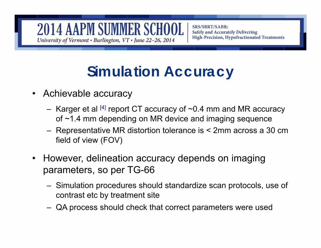
Simulation Accuracy• Achievable accuracy
– Karger et al [4] report CT accuracy of ~0.4 mm and MR accuracy of ~1.4 mm depending on MR device and imaging sequence
– Representative MR distortion tolerance is < 2mm across a 30 cm field of view (FOV)
• However, delineation accuracy depends on imaging parameters, so per TG-66 – Simulation procedures should standardize scan protocols, use of
contrast etc by treatment site– QA process should check that correct parameters were used
U
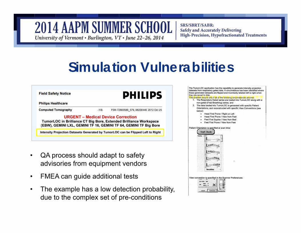
Simulation Vulnerabilities
• QA process should adapt to safety advisories from equipment vendors
• FMEA can guide additional tests
• The example has a low detection probability, due to the complex set of pre-conditions

Fusion• Fusion of MR or PET images can reduce delineation
uncertainties, but contributes its own uncertainties
• For rigid CT / MR registration, achievable accuracy based on phantom studies is ~2 mm. [6]
• Accuracy will degrade if registering to a surrogate, as distance between target & surrogate increases.
• Care should therefore be taken when performing single-isocenter, multi-target treatments, where some targets could be distant from the isocenter. [7]

Fusion• Deformable image registration is work-in-progress. [8,9] QA was
surveyed by Sharpe & Brock (2008) [10], who state: “there is no uniform consensus to guide the development of a comprehensive and prescriptive QA program in this arena” TG-132 is coming soon!
• QA can utilize phantoms, or simulated images, but also depends strongly on visual inspection by experienced operators.
• Receiver operating characteristic (ROC) studies [11,12] suggest visual inspection can reliably detect rigid translations ≥2mm & rotations ≥2°
• To the author’s knowledge, experienced observers’ ability to detect deformable image mis-registrations is not yet quantified
• Automated registration algorithms have the potential for occasional large mis-registrations [11,13]

Fusion• Fusion QA:
– Understand limitations of fusion methods applied to different treatment sites
– Do your own testing
– Provide training
– Ensure treatment process provides adequate review (See TG-132 Assessment Level for fusion quality)

Training MaterialIGRT training can help ensure consistent treatment quality
These examples are from reference [18]: On Target: Ensuring Geometric Accuracy in Radiotherapy. Royal College of Radiologists, 2008.

TG-132 Fusion Assessment LevelUncertaintyAssessment
Phrase Description
0 Whole scan aligned ‐ Anatomy within 1 mm everywhere‐ Useful for structure definition everywhere‐ Ok for stereotactic localization
1 Locally aligned ‐ Anatomy local to the area of interest is un‐distorted and aligned within 1mm‐ Useful for structure definition within the local region‐ Ok for localization provided target is in locally aligned region
2 Useable with risk of deformation
‐ Aligned locally, with mild anatomical variation‐ Acceptable registration required deformation which risks altering anatomy‐ Registered image shouldn’t be used solely for target definition as target may be deformed‐ Increased reliance on additional information is highly recommended‐ Registered image information should be used in complimentary manner and no
image should be used by itself
3 Useable for diagnosis only ‐ Registration not good enough to rely on geometric integrity‐ Possible use to identify general location of lesion (e.g. PET hot spot)
4 Alignment not acceptable ‐ Unable to align anatomy to acceptable levels‐ Patient position variation too great between scans (e.g. surgical resection of the
anatomy of interest or dramatic weight change between scans)

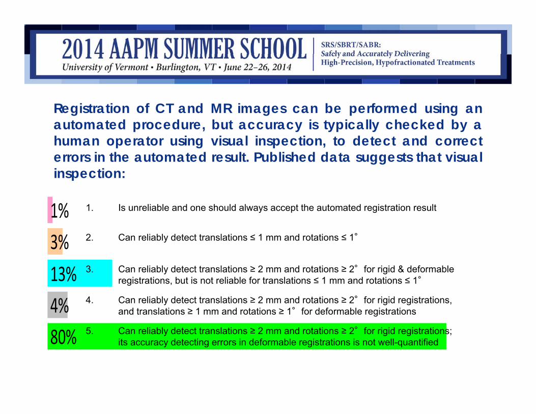
Registration of CT and MR images can be performed using anautomated procedure, but accuracy is typically checked by ahuman operator using visual inspection, to detect and correcterrors in the automated result. Published data suggests that visualinspection:
1. Is unreliable and one should always accept the automated registration result
2. Can reliably detect translations ≤ 1 mm and rotations ≤ 1°
3. Can reliably detect translations ≥ 2 mm and rotations ≥ 2°for rigid & deformable registrations, but is not reliable for translations ≤ 1 mm and rotations ≤ 1°
4. Can reliably detect translations ≥ 2 mm and rotations ≥ 2°for rigid registrations, and translations ≥ 1 mm and rotations ≥ 1°for deformable registrations
5. Can reliably detect translations ≥ 2 mm and rotations ≥ 2°for rigid registrations; its accuracy detecting errors in deformable registrations is not well-quantified
10
Registration of CT and MR images can be performed using anautomated procedure, but accuracy is typically checked by ahuman operator using visual inspection, to detect and correcterrors in the automated result. Published data suggests that visualinspection:
80%4%13%3%1% 1. Is unreliable and one should always accept the automated registration result
2. Can reliably detect translations ≤ 1 mm and rotations ≤ 1°
3. Can reliably detect translations ≥ 2 mm and rotations ≥ 2°for rigid & deformable registrations, but is not reliable for translations ≤ 1 mm and rotations ≤ 1°
4. Can reliably detect translations ≥ 2 mm and rotations ≥ 2°for rigid registrations, and translations ≥ 1 mm and rotations ≥ 1°for deformable registrations
5. Can reliably detect translations ≥ 2 mm and rotations ≥ 2°for rigid registrations; its accuracy detecting errors in deformable registrations is not well-quantified

Correct answer: 5
Ref: Veninga JACMP 5, no. 3 (2004): 66–79. Fitzpatrick IEEE Tr. Medical Imaging 17, no. 4 (1998): 571–85. Brock IJROBP 76, no. 2 (2010): 583–96
1. Is unreliable and one should always accept the automated registration result
2. Can reliably detect translations ≤ 1 mm and rotations ≤ 1°
3. Can reliably detect translations ≥ 2 mm and rotations ≥ 2°for rigid & deformable registrations, but is not reliable for translations ≤ 1 mm and rotations ≤ 1°
4. Can reliably detect translations ≥ 2 mm and rotations ≥ 2°for rigid registrations, and translations ≥ 1 mm and rotations ≥ 1°for deformable registrations
5. Can reliably detect translations ≥ 2 mm and rotations ≥ 2°for rigid registrations; its accuracy detecting errors in deformable registrations is not well-quantified

Treatment Planning• After commissioning has identified appropriate uses and
limitations for the TPS, the goal is to detect deviations
• RPC (now IROC) data suggests ~80% of institutions can achieve dosimetric accuracy of ~7% [14]
• TG-53 [15] provides comprehensive guidelines for QA
• Treatment process should standardize parameters such as beam arrangements, calc. grid size, jaw tracking
• TPS upgrades are a source of changes, so re-testing is required after upgrades

Treatment Planning• Significant change in ability to model small field output
factors between iPlan Dose 4.1 and 4.5
Publication in preparation N. Wen, Y. Huang, Y. Qin
4.5

U
TPS Vulnerabilities
• The example has a low detection probability, due to the complex set of pre-conditions

Patient Setup / Treatment Delivery• Accuracy of setup and delivery is addressed prior to treatment
through standard QA activities
– goal is to ensure radiation and imaging isocenters are aligned and mechanical systems (e.g., 6D couch) perform correctly
– TG-142 Tables I - III list daily, monthly and annual QA for SRS/SBRT
– TG-142 Table VI lists imaging system QA (to be supplemented with QA for additional systems such as Calypso, optical surface matching)
– Respiratory gating system• TG-142 discusses monthly & annual QA• TG-76 Report 91 discusses respiratory motion management in more detail,
including QA recommendations
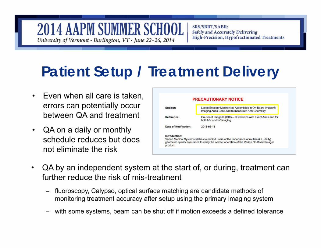
Patient Setup / Treatment Delivery• Even when all care is taken,
errors can potentially occur between QA and treatment
• QA on a daily or monthly schedule reduces but does not eliminate the risk
• QA by an independent system at the start of, or during, treatment can further reduce the risk of mis-treatment
– fluoroscopy, Calypso, optical surface matching are candidate methods of monitoring treatment accuracy after setup using the primary imaging system
– with some systems, beam can be shut off if motion exceeds a defined tolerance

In a 2007 gamma knife treatment in Michigan, a patient was setup for MRI head-first, but the feet-first orientation was selected onthe MRI unit, causing planning images to be left-right reversed.The error was not detected and the dose distribution was shifted18mm across the midline of the brain (wrong-side treatment). Thebest overall strategy to guard against this type of error would be:
1. Always do MRI imaging head-first
2. Ensure the planning physicist is present at simulation
3. Provide training to the MRI staff
4. Check the orientation of imported image sets in the treatment planning system
5. Ensure redundant methods exist to verify patient setup at simulation, planning and treatment are consistent

In a 2007 gamma knife treatment in Michigan, a patient was setup for MRI head-first, but the feet-first orientation was selected onthe MRI unit, causing planning images to be left-right reversed.The error was not detected and the dose distribution was shifted18mm across the midline of the brain (wrong-side treatment). Thebest overall strategy to guard against this type of error would be:
93%7%0%1%0% 1. Always do MRI imaging head-first
2. Ensure the planning physicist is present at simulation
3. Provide training to the MRI staff
4. Check the orientation of imported image sets in the treatment planning system
5. Ensure redundant methods exist to verify patient setup at simulation, planning and treatment are consistent

Correct answer: 5
Ref: Gamma knife treatment to wrong side of brain. Event Notification Report 43746. United States Nuclear Regulatory Commission (2007)
1. Always do MRI imaging head-first
2. Ensure the planning physicist is present at simulation
3. Provide training to the MRI staff
4. Check the orientation of imported image sets in the treatment planning system
5. Ensure redundant methods exist to verify patient setup at simulation, planning and treatment are consistent
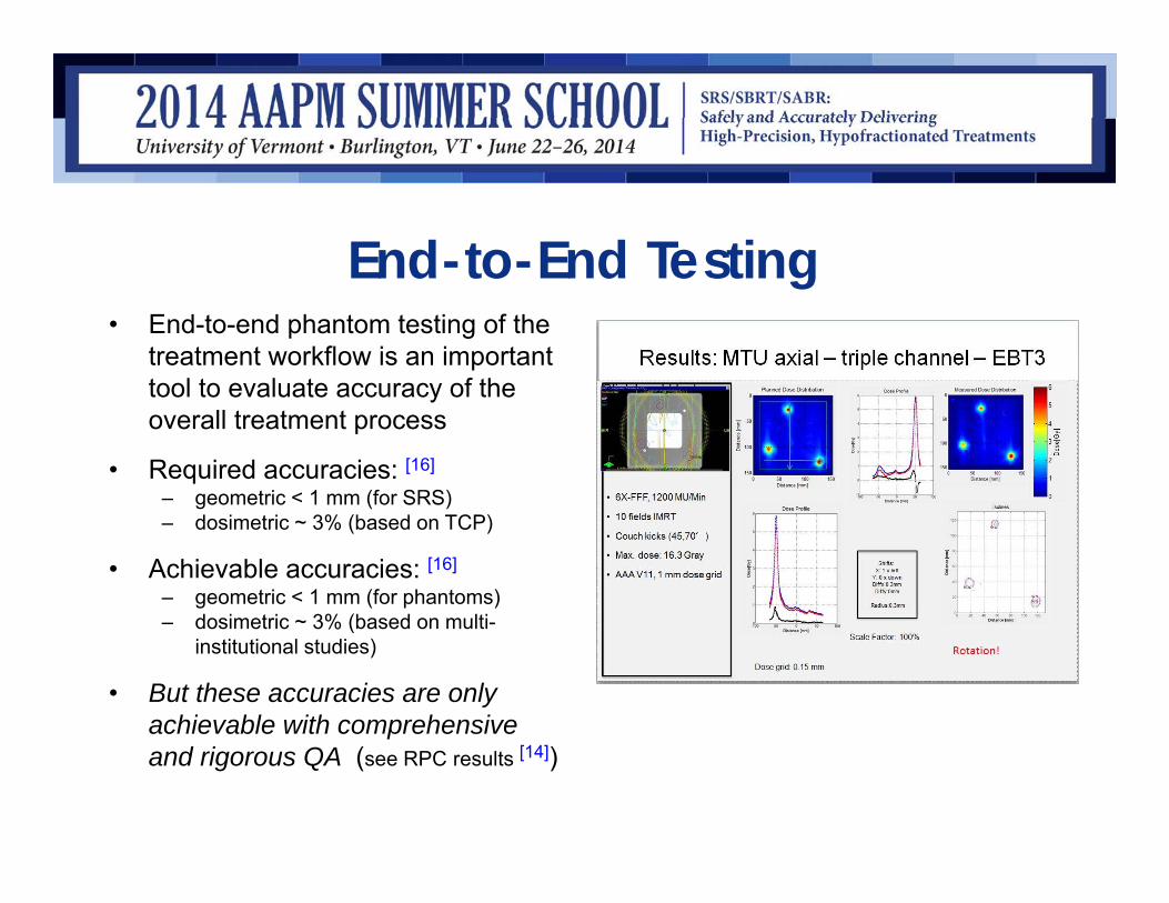
End-to-End Testing• End-to-end phantom testing of the
treatment workflow is an important tool to evaluate accuracy of the overall treatment process
• Required accuracies: [16]
– geometric < 1 mm (for SRS)– dosimetric ~ 3% (based on TCP)
• Achievable accuracies: [16]
– geometric < 1 mm (for phantoms)– dosimetric ~ 3% (based on multi-
institutional studies)
• But these accuracies are only achievable with comprehensive and rigorous QA (see RPC results [14])

Conclusions• Error rates in RT are small (e.g., 0.1% / field) and rates of severe /
reportable errors are at least an order of magnitude smaller
• However, this still ensures the mean time between errors in a clinic is months or a few years
• Use of redundant / independent checks can reduce an error rate from e.g., 0.1% to 0.0001%
• Some future challenges are: – to implement real-time error-checking at the time of treatment
– by automating data collection, to move RT closer to a modern systems control approach, that uses quantitative data to maintain RT quality within tight limits [17]

References[1] Mutic, Sasa, Jatinder R. Palta, Elizabeth K. Butker, Indra J. Das, M. Saiful Huq, Leh-Nien Dick Loo, Bill J. Salter, Cynthia H.
McCollough, and Jacob Van Dyk. “Quality Assurance for Computed-Tomography Simulators and the Computed-Tomography-Simulation Process: Report of the AAPM Radiation Therapy Committee Task Group No. 66.” Medical Physics 30, no. 10 (2003): 2762.
[2] Phantom Test Guidance for Use of the Small MRI Phantom for the MRI Accreditation Program http://www.acr.org/~/media/ACR/Documents/Accreditation/MRI/SmallPhantomGuidance.pdf
[3] Phantom Test Guidance for Use of the Small MRI Phantom for the MRI Accreditation Program http://www.acr.org/~/media/ACR/Documents/Accreditation/MRI/LargePhantomInstructions.pdf
[4] Karger, Christian P, Peter Hipp, Marcus Henze, Gernot Echner, Angelika Höss, Lothar Schad, and Günther H Hartmann. “StereotacticImaging for Radiotherapy: Accuracy of CT, MRI, PET and SPECT.” Physics in Medicine and Biology 48, no. 2 (2003): 211–21.
[5] Philips Field Safety Notice FSN 72800586_579, 88200446 2012 Oct 25, TumorLOC in Brilliance CT Big Bore, Extended Brilliance Workspace (EBW), GEMINI LXL, GEMINI TF 16, GEMINI TF 64, GEMINI TF Big Bore, Intensity Projection Datasets Generated by TumorLOC can be Flipped Left to Right
[6] Jonker, Benjamin P. “Image Fusion Pitfalls for Cranial Radiosurgery.” Surgical Neurology International 4(Suppl 3) (2013): S123–8.[7] Clark, Grant M, Richard A Popple, P Edward Young, and John B Fiveash. “Feasibility of Single-Isocenter Volumetric Modulated Arc
Radiosurgery for Treatment of Multiple Brain Metastases.” International Journal of Radiation Oncology, Biology, Physics 76, no. 1 (January 1, 2010): 296–302.
[8] Brock, Kristy K, and Deformable Registration Accuracy Consortium. “Results of a Multi-Institution Deformable Registration Accuracy Study (MIDRAS).” International Journal of Radiation Oncology, Biology, Physics 76, no. 2 (February 1, 2010): 583–96.
[9] Stanley, Nick, Carri Glide-Hurst, Jinkoo Kim, Jeffrey Adams, Shunshan Li, Ning Wen, Indrin J. Chetty, and Hualiang Zhong. “Using Patient-Specific Phantoms to Evaluate Deformable Image Registration Algorithms for Adaptive Radiation Therapy.” Journal of Applied Clinical Medical Physics 14, no. 6 (November 4, 2013).
[10] Sharpe, Michael, and Kristy K. Brock. “Quality Assurance of Serial 3D Image Registration, Fusion, and Segmentation.” International Journal of Radiation Oncology*Biology*Physics, Quality Assurance for Radiation Therapy Quality Assurance of Radiation Therapy: The Challenges of Advanced Technologies Symposium, 71, no. 1, Supplement (May 1, 2008): S33–S37.
[11] Fitzpatrick, J.M., D. L G Hill, Y. Shyr, J. West, C. Studholme, and C.R. Maurer. “Visual Assessment of the Accuracy of Retrospective Registration of MR and CT Images of the Brain.” IEEE Transactions on Medical Imaging 17, no. 4 (August 1998): 571–85.

References[12] Veninga, Theo, Henkjan Huisman, Richard W M van der Maazen, and Henk Huizenga. “Clinical Validation of the Normalized Mutual
Information Method for Registration of CT and MR Images in Radiotherapy of Brain Tumors.” Journal of Applied Clinical Medical Physics / American College of Medical Physics 5, no. 3 (2004): 66–79.
[13] Yeo, U J, J R Supple, M L Taylor, R Smith, T Kron, and R D Franich. “Performance of 12 DIR Algorithms in Low-Contrast Regions for Mass and Density Conserving Deformation.” Medical Physics 40, no. 10 (October 2013): 101701. doi:10.1118/1.4819945.
[14] Molineu, Andrea, Nadia Hernandez, Trang Nguyen, Geoffrey Ibbott, and David Followill. “Credentialing Results from IMRT Irradiations of an Anthropomorphic Head and Neck Phantom.” Medical Physics 40, no. 2 (February 2013).
[15] Fraass, B., K. Doppke, M. Hunt, G. Kutcher, G. Starkschall, R. Stern, and J. Van Dyke. “AAPM Report 62 - TG-53 - QA for Clinical Radiotherapy Treatment Planning.” Medical Physics 25, no. 10 (1998): 1773–1829.
[16] Thwaites, David. “Accuracy Required and Achievable in Radiotherapy Dosimetry: Have Modern Technology and Techniques Changed Our Views?” Journal of Physics: Conference Series 444, no. 1 (June 26, 2013).
[17] Bujold, Alexis, Tim Craig, David Jaffray, and Laura A Dawson. “Image-Guided Radiotherapy: Has It Influenced Patient Outcomes?” Seminars in Radiation Oncology 22, no. 1 (January 2012): 50–61.
[18] On Target: Ensuring Geometric Accuracy in Radiotherapy. Royal College of Radiologists, 2008. (At time of writing available at: http://www.rcr.ac.uk/docs/oncology/pdf/BFCO(08)5_On_target.pdf )