Equipment design Ethylbenzene production by liquid phase Done by: Mohammed Almohsen Supervised By:...
41
Equipment design Ethylbenzene production by liquid phase Done by: Mohammed Almohsen Supervised By: Prof. M. A. Fahim Eng. Yusuf Ismail KUWAIT UNIVERSITYCOLLEGE OF ENGINEERING & PETROLEUMCHEMICAL ENGINEERING DEPARTMENT
-
Upload
elvin-williams -
Category
Documents
-
view
236 -
download
1
Transcript of Equipment design Ethylbenzene production by liquid phase Done by: Mohammed Almohsen Supervised By:...

Equipment designEthylbenzene production by liquid phase
Done by: Mohammed Almohsen
Supervised By:
Prof. M. A. Fahim
Eng. Yusuf Ismail
KUWAIT UNIVERSITYCOLLEGE OF ENGINEERING & PETROLEUMCHEMICAL ENGINEERING DEPARTMENT

Distillation column:
Distillation T-101
Separate and recycle Ethylbenzene
COLUMN DIAMETER:
LIQUID VAPOR FLOW FACTOR
FOR BOTTOMS FOR TOP
TAKE PLATE SPACING AS 0.6 M
BASE K1 = 0.08TOP K1 = 0.12
BASE K1 = 0.066TOP K1 = 0.1078
CORRECTION FOR SURFACE TENSIONS
FROM FIGURE

FLOODING VELOCITY:
DESIGN FOR 85% FLOODING AT MAXIMUM FLOW RATE
BASE
TOP

MAXIMUM VOLUMETRIC FLOW RATE
BOTTOM TOP
NET AREA REQUIRED:
TAKING DOWNCOMER AREA AS 12 per cent OF TOTAL AREA
COLUMN CROSS-SECTIONAL AREA
COLUMN DIAMETER:
USE SAME DIAMETER ABOVE AND BELOW FEED =6.328M=20.76FT

COLUMN HEIGHT:
Column height = (Number of stage * Plate spacing) + Column Diameter
H = 27.9m =91.6 FT

LIQUID FLOW PATTERN:MAXIMUM VOLUMETRIC LIQUID
RATE
DOUBLE PASS PLATE IS USED
FROM FIGURE

PROVISIONAL PLATE DESIGN:
•Column diameter =
•Column area =
•Downcomer area =
•Net area =
•Active area =
•Hole area =

WEIR LENGTH
FROM FIGURE
•Take weir height =
•Hole diameter =
•Plate thickness =
ASSUME

CHECK WEEPING:
MAXIMUM LIQUID RATE
TURNDOWN PERCENTAGE = 0.80
MINIMUM LIQUID RATE
MAXIMUM WEIR CREST:
MINIMUM WEIR CREST:

AT MINIMUM RATE
FROM FIGURE
MINIMUM VAPOR VELOCITY THROUGH HOLE:
ACTUAL MINIMUM VAPOR VELOCITY
SO MINIMUM OPERATING RATE WILL BE ABOVE WEEP POINT.

PLATE PRESSURE DROP:MAXIMUM VAPOR VELOCITY THROUGH
HOLES
Plate thickness / hole dia. = 1.25
FROM FIGURE
DRY PLATE DROP
RESIDUAL DROP
TOTAL PLATE PRESSURE DROP

DOWN COMER LIQUID BACK-UP:DOWNCOMER PRESSURE
LOSSTAKE
AREA UNDER APRON
HEAD LOSS IN THE DOWNCOMER
BACK-UP IN DOWNCOMER
CHECK RESIDENCE TIME
SATISFACTORY

CHECK ENTRAINMENT
ψ =0.013 , well below 0.1
FROM FIGURE

PERFORATED AREA:
FROM FIGURE
•Angle subtended by the edge of the plate = 85
•Mean length, unperforated edge strips = 9.3136
•Area of unperforated edge strips=0.4191 m
•Mean length of calming zone,approx =4.7738
•Area of calming zones =0.4296 m
•Total area for perforations, Ap =23.0532

FROM FIGURE
NUMBER OF HOLES:AREA OF ONE HOLE:
NUMBER OF HOLES:

AREA OF CONDENSER
AREA OF REBOILER
Inlet temperature T1 231.8769 Co
Outlet temperature T2 230.4711 Co
Mean overall heat transfer coefficient U
1000.0000 W/m2.Co
Heat flow Q 50810.0000 KW
Inlet temperature T1 159.8721 Co
Outlet temperature T2 158.5811 Co
Mean overall heat transfer coefficient U
1000.0000 W/m2.Co
Heat flow Q 52720.0000 KW

THICKNESS CALCULATIONS:
Internal raduis of shell before allowance corrosion is added ri
124.567 in
Maximum allowable internal pressure P 100.000 psi
Working stress for carbon steel S 13706.660 psi
Efficincy of joients EJ 0.850
Allowance for corrosin Cc 0.125 in

Equipment Name Benzene Column
Objective Separate and recycle Benzene to the reactor
Equipment Number T-101
Designer Mohammed Al-Mohsen
Type Continuous Distillation Column
Location After Mixer (MIX-108)
Material of Construction Carbon steel
Insulation Mineral wool
Cost ($) $711,828
Operating Condition
Operating Temperature (oC) 171
Operating Pressure (psi) 100
Feed Flow Rate (kg/h) 451181
Diameter (m) 6.328
Height (m) 27.9
Thickness (mm) 30.47
SPECIFICATION SHEET OF BENZENE COLUMN T-101

COST CALCULATIONS:
• Column cost:
• Cost of tray = 1,100 $/trays
• Cost of trays = 52,800$
• Cost of Vessel:
• Diameter outside=6m
• Volume outside=895
• Volume inside=878
• Volume of metal=17
• Weight of metal=296,080lb
• Cost of vessel 2007 =547,200$
• Vessel type: Large ,No Internals , Medium
• Cost of reboiler:
• Cost 2007 = 39,300$
• Cost of condenser:
• Cost 2007 =19,800$
• Total cost of without insulation=659,100$
• Insulation cost = 52,728$
• Total cost of T-101=711,828$
FROM:WWW.MATCHE.COM
Heat exchanger:
3 heat exchanger has been designE-102 ,E103 and e-105.
The type of the 3 heat exchanger are shell and tube.

Cooler E-102 detailed calculation:
• Heat load:
•
COOLING FLOW:
ASSUMETRY AND ERROR
BECAUSE THERE IS PHASE CHANGE
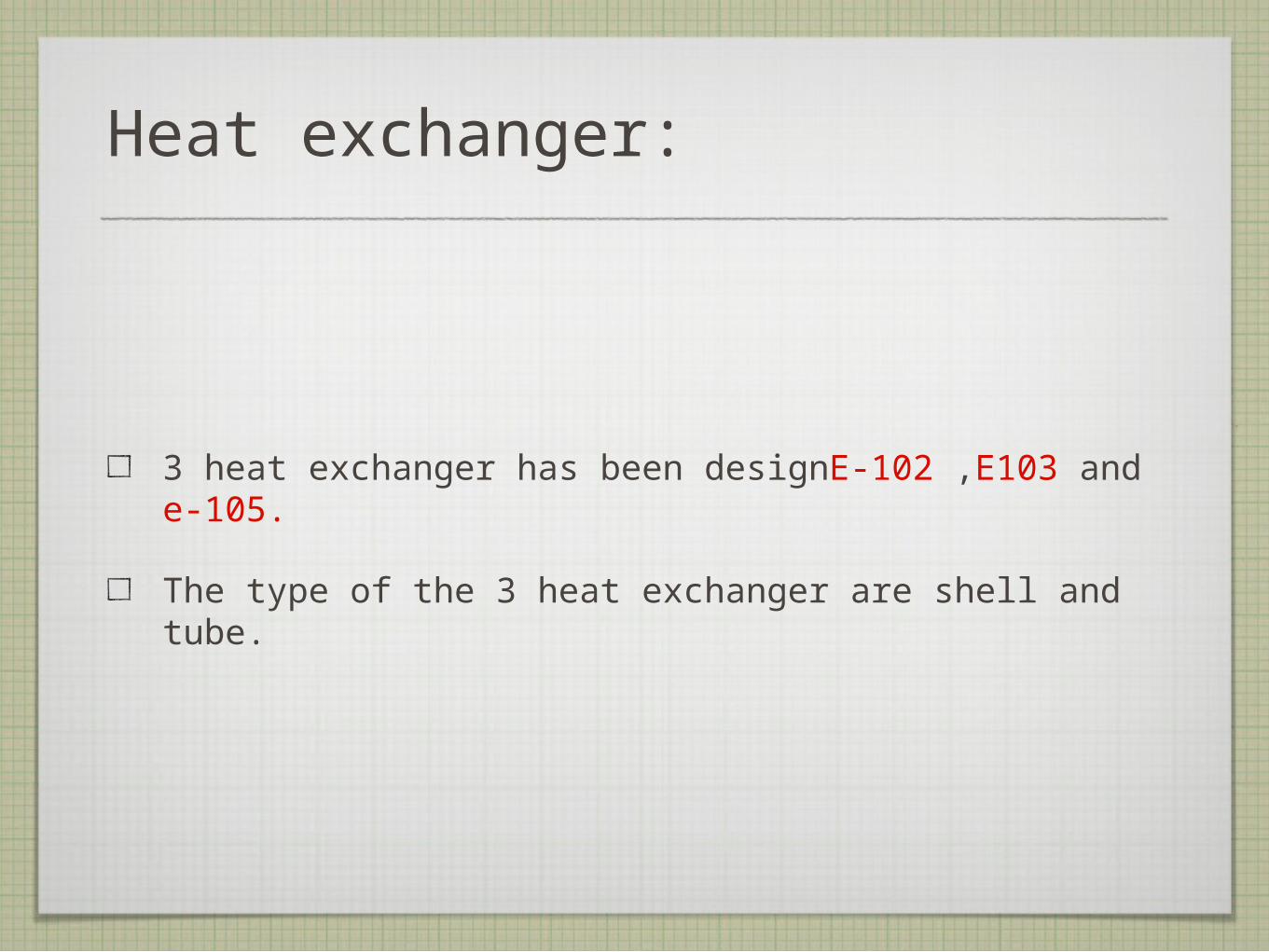
TEMPERATURE CORRECTION FACTOR: CALCULATION:
USING ONE SHELL PASS AND TWO TUBE PASSES
FROM FIGURE

ASSUME
PROVISIONAL AREA:
CHOOSE TUBE MATERIAL TO BE carbon steel WITH THE FOLLOWING PROPERTYOUTER DIAMETER Do = 25 MMINNER DIAMETER Di = 20 MMTUBE LENGTH = 4.88 M

AREA OF ONE TUBE
NUMBER OF TUBES
Nt = provisinal area / area of one tube = 792.36 = 793
USING 1.25 TRIANGULAR PITCH
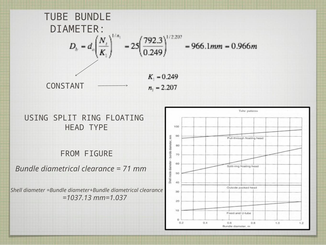
TUBE BUNDLE DIAMETER:
CONSTANT
USING SPLIT RING FLOATING HEAD TYPE
Bundle diametrical clearance = 71 mm
FROM FIGURE
Shell diameter =Bundle diameter+Bundle diametrical clearance
=1037.13 mm=1.037

TUBE-SIDE COEFFICIENT: METHOD 1
• Mean water temperature =
• Tube cross sectional area =
• Total flow area=Tubes per pass x Cross
sectional area=

• Water mass velocity=mass flow rate/total flow
area=
• Water linear velocity Ut = mass velocity /
density =
• Inside coefficient for water hi:

TUBE-SIDE COEFFICIENT: METHOD 1I
•REYNALDO NUMBER
•PRANDTL NUMBER
HEAT TRANSFER FACTOR
FROM FIGURE

•INSIDE COEFFICIENT FOR WATER
Hs:

SHELL-SIDE COEFFICIENT:
• Choose baffle spacing =
• Tube pitch =
• Cross flow area=
• Mass velocity Gs= mass flow rate/cross flow
area =

• Equivalent diameter for triangular arrangement
• Mean shell side diameter temperature:
• Reynaldo number
• Prandtl number

CHOOSE 25% BAFFLE CUT
FROM FIGURE
HEAT TRANSFER FACTOR

OVERALL HEAT TRANSFER COEFFICIENT:
• Thermal conductivity of steel =
• Outside coefficient (fouling factor) =
• Inside coefficient (fouling factor) =
CLOSE TO INITIAL VALUE ASSUMED

PRESSURE DROP:
TUBE SIDE:
FROM FIGURE
HEAT TRANSFER FACTOR

SHELL SIDE:
FROM FIGURE
Linear velocity =

Internal raduis of shell before allowance
corrosion is added ri 20.416 in
Maximum allowable internal pressure P
85 psi
Working stress for carbon steel S
13706.66 psi
Efficincy of joients EJ 0.85
Allowance for corrosin Cc
0.125 in
SHELL THICKNESS CALCULATIONS:

• Cost Calculations:
•From www.matche.com
•Heat transfer area = 3,269 ft2
•Exchanger Type: Carbon steel
•Internal Pressure: 450 psi
•Cost with out insulation: 110,900$
•Insulation cost: 8,872$
•Final cost 2007:119,772$

Equipment Name Heat exchanger
Objective Heat the Benzene recycled stream before feed to the distillation
Equipment Number E-102
Designer Mohammed Al-Mohsen
Type Shell and Tube Heat Exchanger
Location After E-103 Heat Exchanger
Utility Cooling Water
Material of Construction Cupro Nickel for shell sideCarbon Steel for tube side
Insulation Glass wool
Cost ($) $110,900
Operating Condition
Shell Side
Inlet temperature (C) 159.38Outlet temperature
(C)158.58
Tube Side
Inlet temperature (C) 27Outlet temperature
(C)78
Number of Tube Rows 2 Number of Tubes 793
Tube bundle Diameter (m)
0.966 Shell Diameter (m) 1.037
Q total (kW) 22617 LMTD (oC) 104.48
U (W/m2C) 738Heat Exchanger Area
(m2)303.69

Equipment Name Heat exchanger
Objective Heat the polyethylbenzen recycled stream before feed to Trans-reactor
Equipment Number E-105
Designer Mohammed Al-Mohsen
Type Shell and Tube Heat Exchanger
Location After P-101 pump
Utility Cooling Water
Material of Construction Cupro Nickel for shell sideCarbon Steel for tube side
Insulation Glass wool
Cost ($) $110,880
Operating Condition
Shell Side
Inlet temperature (C) 247.8Outlet temperature
(C)127.5
Tube Side
Inlet temperature (C) 27Outlet temperature
(C)45
Number of Tube Rows 4 Number of Tubes 12
Tube bundle Diameter (m)
0.157 Shell Diameter (m) 0.205
Q total (kW) 256.5 LMTD (oC) 145.69
U (W/m2oC) 608.4Heat Exchanger Area
(m2)2.736
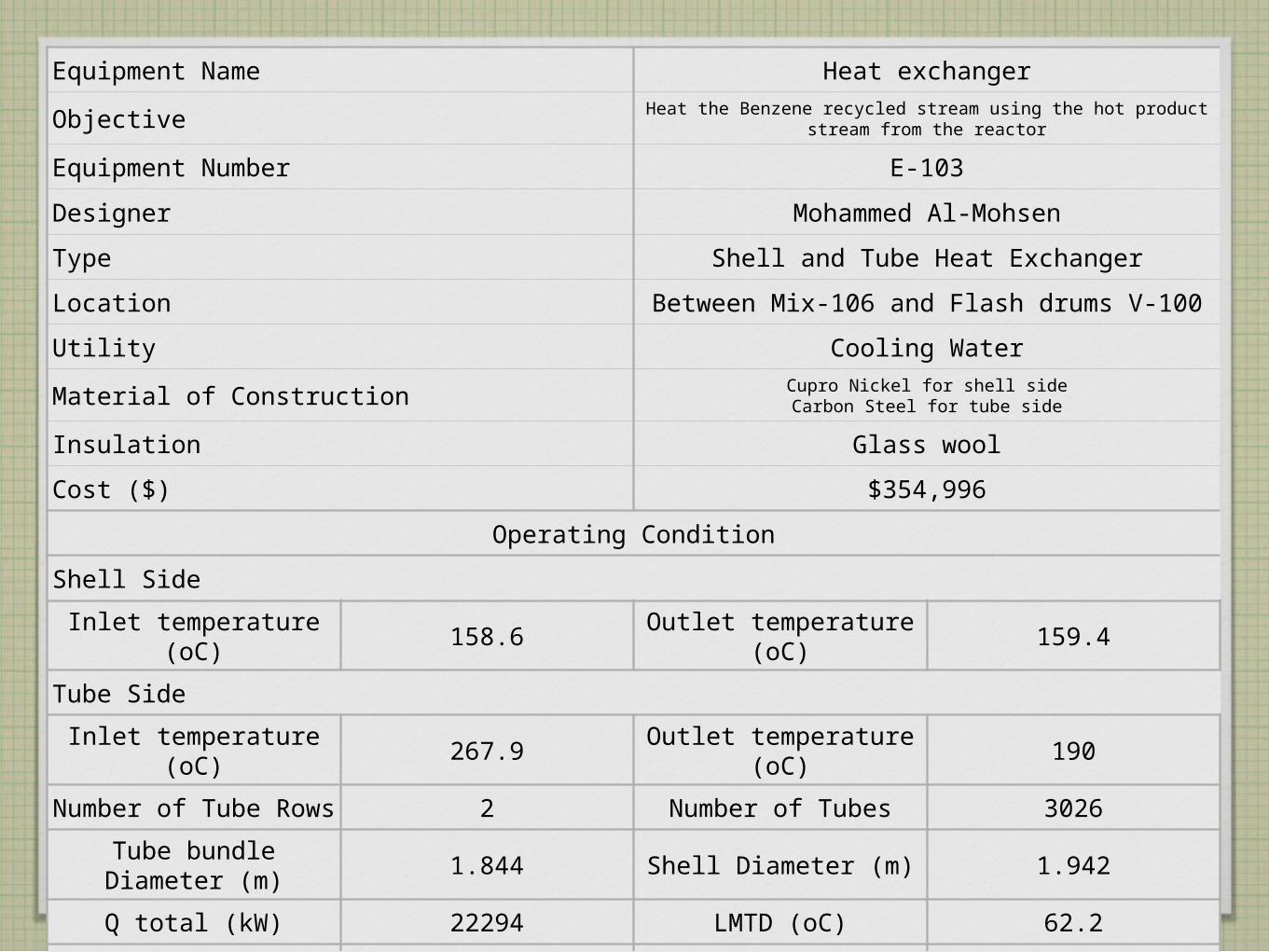
Equipment Name Heat exchanger
Objective Heat the Benzene recycled stream using the hot product stream from the reactor
Equipment Number E-103
Designer Mohammed Al-Mohsen
Type Shell and Tube Heat Exchanger
Location Between Mix-106 and Flash drums V-100
Utility Cooling Water
Material of Construction Cupro Nickel for shell sideCarbon Steel for tube side
Insulation Glass wool
Cost ($) $354,996
Operating Condition
Shell Side
Inlet temperature (oC) 158.6Outlet temperature
(oC)159.4
Tube Side
Inlet temperature (oC) 267.9Outlet temperature
(oC)190
Number of Tube Rows 2 Number of Tubes 3026
Tube bundle Diameter (m)
1.844 Shell Diameter (m) 1.942
Q total (kW) 22294 LMTD (oC) 62.2
U (W/m2oC) 334.755Heat Exchanger Area
(m2)12987