EQN 1135 ECN 1123 - Heidenhain...ECN 1123, EQN 1135 Rotary encoders for absolute position values...
7
Product Information ECN 1123 EQN 1135 Absolute Rotary Encoders with 1KA Positive-Locking Hollow Shaft for Safety-Related Applications 06/2018
Transcript of EQN 1135 ECN 1123 - Heidenhain...ECN 1123, EQN 1135 Rotary encoders for absolute position values...

Product Information
ECN 1123EQN 1135
Absolute Rotary
Encoders with 1KA
Positive-Locking Hollow
Shaft for Safety-Related
Applications
06/2018
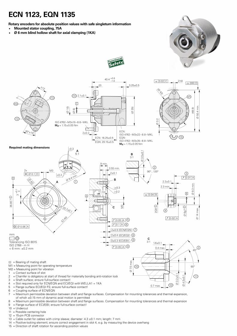
ECN 1123, EQN 1135
Rotary encoders for absolute position values with safe singleturn information
• Mounted stator coupling, 75A
• Ø 6 mm blind hollow shaft for axial clamping (1KA)
= Bearing of mating shaft
M1 = Measuring point for operating temperature
M2 = Measuring point for vibration
1 = Contact surface of slot
2 = Chamfer is obligatory at start of thread for materially bonding anti-rotation lock
3 = Shaft surface; ensure full-surface contact!
4 = Slot required only for ECN/EQN and ECI/EQI with WELLA1 = 1KA
5 = Flange surface ECI/EQI FS; ensure full-surface contact!
6 = Coupling surface of ECN/EQN
7 = Maximum permissible deviation between shaft and flange surfaces. Compensation for mounting tolerances and thermal expansion,
of which ±0.15 mm of dynamic axial motion is permitted
8 = Maximum permissible deviation between shaft and flange surfaces. Compensation for mounting tolerances and thermal expansion
9 = Flange surface of ECI/EBI; ensure full-surface contact!
10 = Undercut
11 = Possible centering hole
12 = 15-pin PCB connector
13 = Cable outlet for cables with crimp sleeve; diameter: 4.3 ±0.1 mm; length: 7 mm
14 = Positive-locking element; ensure correct engagement in slot 4, e.g. by measuring the device overhang
15 = Direction of shaft rotation for ascending position values
Required mating dimensions

Specifications
Specifications ECN 1123 – Singleturn EQN 1135 – Multiturn
ID number 743586-01 743587-01
Functional safety
for applications up to
As single-encoder system for monitoring functions:
• SIL 1 as per EN 61508 (further basis for testing: EN 61800-5-2)
• Category 2, PL c as per EN ISO 13849-1:2015
As single-encoder system for closed-loop functions:
• SIL 2 as per EN 61508 (further basis for testing: EN 61800-5-2)
• Category 3, PL d as per EN ISO 13849-1:2015
Safe in singleturn operation
PFH ≤ 15 · 10 –9 (probability of dangerous failure per hour)
Safe position 1) Encoder: ±1.75° (safety-related measuring step: SM = 0.7°)
Mechanical coupling: ±2° (fault exclusion for loosening of shaft coupling and stator coupling; designed
for accelerations of ≤ 300 m/s 2 )
Interface EnDat 2.2
Ordering designation EnDat22
Position values per rev. 8 388 608 (23 bits)
Revolutions - 4096 (12 bits)
Calculation time tcal
Clock frequency
≤ 7 µs
≤ 8 MHz
System accuracy ±60"
Electrical connection 15-pin PCB connector (with connection for external temperature sensor 3) )
Cable length ≤ 100 m (see EnDat description in the Interfaces of HEIDENHAIN Encoders brochure)
Supply voltage DC 3.6 V to 14 V
Power consumption 2) (max.) At 3.6 V: ≤ 600 mW
At 14 V: ≤ 700 mW
At 3.6 V: ≤ 700 mW
At 14 V: ≤ 800 mW
Current consumption (typical) At 5 V: 85 mA (without load) At 5 V: 105 mA (without load)
Shaft Blind hollow shaft, Ø 6 mm, with positive-locking element (1KA)
Speed ≤ 12 000 rpm
Starting torque 4) at 20 °C ≤ 0.001 Nm ≤ 0.002 Nm
Moment of inertia Rotor: 0.4 · 10 –6 kgm 2 ; stator: 1.0 · 10 –5 kgm 2
Angular acceleration Rotor: ≤ 1 · 10 5 rad/s 2 ; stator: ≤ 1 · 10 4 rad/s 2
Axial motion of measured shaft ≤ ±0.5 mm
Natural frequency of stator coupling ≥ 1000 Hz
Vibration 55 Hz to 2 000 Hz
Shock 6 ms
≤ 200 m/s 2 (EN 60068-2-6); 10 Hz to 55 Hz constant over 3.2 mm peak to peak
≤ 2000 m/s 2 (EN 60068-2-27)
Operating temperature –40 °C to 110 °C
Trigger threshold of error message
for excessive temperature
125 °C (measuring accuracy of internal temperature sensor: ±5 K)
Relative humidity ≤ 93 % (40 °C/21 d as per EN 60068-2-78); condensation excluded
Protection EN 60529 IP40 (see Insulation under General mechanical information in the Encoders for Servo Drives brochure;
contamination from the ingress of liquid must be prevented)
Mass ≈ 0.1 kg
1) Further tolerances may apply in the subsequent electronics after position value comparison (contact mfr. of subsequent electronics)
2) See General electrical information in the Interfaces of HEIDENHAIN Encoders brochure
3) See Temperature measurement in motors in the Encoders for Servo Drives brochure
4) Comply with the maximum torque when designing the mechanical fault exclusion (page 4)

Mounting
The blind hollow shaft of the rotary encoder is slid onto the measured shaft and fastened with
a central screw. It is particularly important to ensure that the positive-locking element of the
encoder shaft securely engages the corresponding slot in the measured shaft. The stator is
connected without a centering collar to a flat surface with two clamping screws. Use screws
with materially bonding anti-rotation lock (see Mounting accessories).
The following material properties and conditions must be complied with when planning and
executing customer-side installation:
Mating stator Mating shaft
Material Aluminum Steel
Tensile strength Ra ≥ 220 N/mm 2 ≥ 600 N/mm 2
Yield strength Rp0.2 or yield point Re - ≥ 400 N/mm 2
Shear strength τa 130 N/mm 2 ≥ 390 N/mm 2
Interface pressure PG ≥ 250 N/mm 2 ≥ 660 N/mm 2
Modulus of Elasticity E (at 20 °C) 70 kN/mm 2 to
75 kN/mm 2
200 kN/mm 2 to
215 kN/mm 2
Coefficient of thermal expansion αtherm
(at 20 °C)
≤ 25 · 10 –6 K –1 10 · 10 –6 K –1 to
17 · 10 –6 K –1
Surface roughness RZ ≤ 16 µm
Friction values Mounting surfaces must be clean and free of
grease. Use screws and washers in the condition
as delivered.
Tightening process Use a signaling torque tool as per
DIN EN ISO 6789; accuracy ±6 %
Mounting temperature 15 °C to 35 °C
When designing the mechanical fault exclusion for the shaft connection, use the following
maximum torque Mmax:
Mmax = 1.0 Nm
The mechanical design on the customer side must ensure that the maximum torque Mmax
occurring in the application can be transmitted.
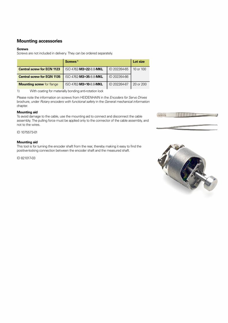
Mounting accessories
Screws
Screws are not included in delivery. They can be ordered separately.
Screws 1) Lot size
Central screw for ECN 1123 ISO 4762-M3×22-8.8-MKL ID 202264-65
Central screw for EQN 1135 ISO 4762-M3×35-8.8-MKL ID 202264-66
10 or 100
Mounting screw for flange ISO 4762-M3×10-8.8-MKL ID 202264-87 20 or 200
1) With coating for materially bonding anti-rotation lock
Please note the information on screws from HEIDENHAIN in the Encoders for Servo Drives
brochure, under Rotary encoders with functional safety in the General mechanical information
chapter.
Mounting aid
To avoid damage to the cable, use the mounting aid to connect and disconnect the cable
assembly. The pulling force must be applied only to the connector of the cable assembly, and
not to the wires.
ID 1075573-01
Mounting aid
This tool is for turning the encoder shaft from the rear, thereby making it easy to find the
positive-locking connection between the encoder shaft and the measured shaft.
ID 821017-03

Electrical Connection – Cable
Output cables inside the motor housing
Complete with 15-pin PCB connector and 8-pin
M12 flange socket (male); TPE single wires in
braided sleeve and wires for temperature sensor
TPE 10 × 0.16 mm 2 1) 2)
ID 1117412-xx
One 15-pin PCB connector and free cable end
(unstripped); Ø 3.7 mm EPG (with shield crimp
sleeve: Ø 4.3 mm) and wires for temperature
sensor
EPG 1 × (4 × 0.06 mm 2 ) + 4 × 0.06 mm 2 2)
TPE 2 × 0.16 mm 2
ID 1108078-xx
1) Single wires with braided sleeve
2) Shield connection required on the motor side
Note for safety-related applications: Document the bit error rate in accordance with Specification 533095!
PUR adapter cables and connecting cables
Ø 6 mm; 2 × (2 × 0.09 mm 2 ) + 2 × (2 × 0.16 mm 2 ); AP = 0.16 mm 2
8-pin M12 connector
Adapter cable with 8-pin M12 connector (female)
and 15-pin D-sub connector (male) for IK 215,
PWM 21, EIB 741, etc.
ID 1036526-xx
Adapter cable with 8-pin angled M12 connector
(female) and 15-pin D-sub connector (male) for
IK 215, PWM 21, EIB 741, etc.
ID 1133855-xx
Connecting cable with 8-pin M12 connector
(female) and 8-pin M12 coupling (male)
ID 1036372-xx
Connecting cable with 8-pin angled M12
connector (female) and 8-pin M12 coupling (male)
ID 1036386-xx
Connecting cable with 8-pin M12 connector
(female) and free cable end (unstripped)
ID 1129581-xx 1)
Connecting cable with 8-pin angled M12
connector (female) and free cable end (unstripped)
ID 1133799-xx 1)
AP: Cross section of power supply lines
1) Use connecting elements for 8 MHz signal transmission
Note for safety-related applications:
• Document the bit error rate in accordance with Specification 533095!
• CE compliance of the complete system must be documented!

Electrical connection – pin layout
Pin layout
8-pin M12 coupling
or flange socket
15-pin PCB connector
Power supply Serial data transfer Other signals 1)
M12 8 2 5 1 3 4 7 6 / /
13 11 14 12 7 8 9 10 5 6
UP Sensor UP 0 V Sensor 0 V DATA DATA CLOCK CLOCK T+ 2) T– 2)
Brown/
Green
Blue White/
Green
White Gray Pink Violet Yellow Brown Green
1) Only for encoder cables within the motor housing
2) Connections for external temperature sensor; evaluation optimized for KTY 84-130 (see Temperature measurement in motors in the
Encoders for Servo Drives brochure)
Cable shield connected to housing; Up = Power supply
Sensor: The sense line is connected in the encoder with the corresponding power line.
Vacant pins and wires must not be used!
Note for safety-related applications: Only completely assembled HEIDENHAIN cables are qualified. Do not modify cables or exchange
their connectors without first consulting with HEIDENHAIN Traunreut!
This Product Information document supersedes all previous editions, which thereby
become invalid. The basis for ordering from HEIDENHAIN is always the Product
Information document edition valid when the order is made.
Further information: Adhere to the information in the following documents to
ensure the correct and intended operation of the encoder:
• Encoders for Servo Drives brochure: 208922-xx
• Mounting instructions for ECN 1123, EQN 1135: 816487-xx
• Safety-Related Position Measuring Systems Technical Information document: 596632
• For implementation in a safe control or inverter, refer to Specification 533095750816 · 05 · A · 01 · 05/2018 · PDF