
eqckt indmotor
61
8/6/2013 PRB/EEE Dept/SCE 1 Phasor diagram of induction motor (Induction motor as a Generalized Transformer)
-
Upload
ramesh-babu -
Category
Documents
-
view
214 -
download
0
description
induction motor
Transcript of eqckt indmotor

8/6/2013 PRB/EEE Dept/SCE 1
Phasor diagram of induction motor
(Induction motor as a Generalized Transformer)
2
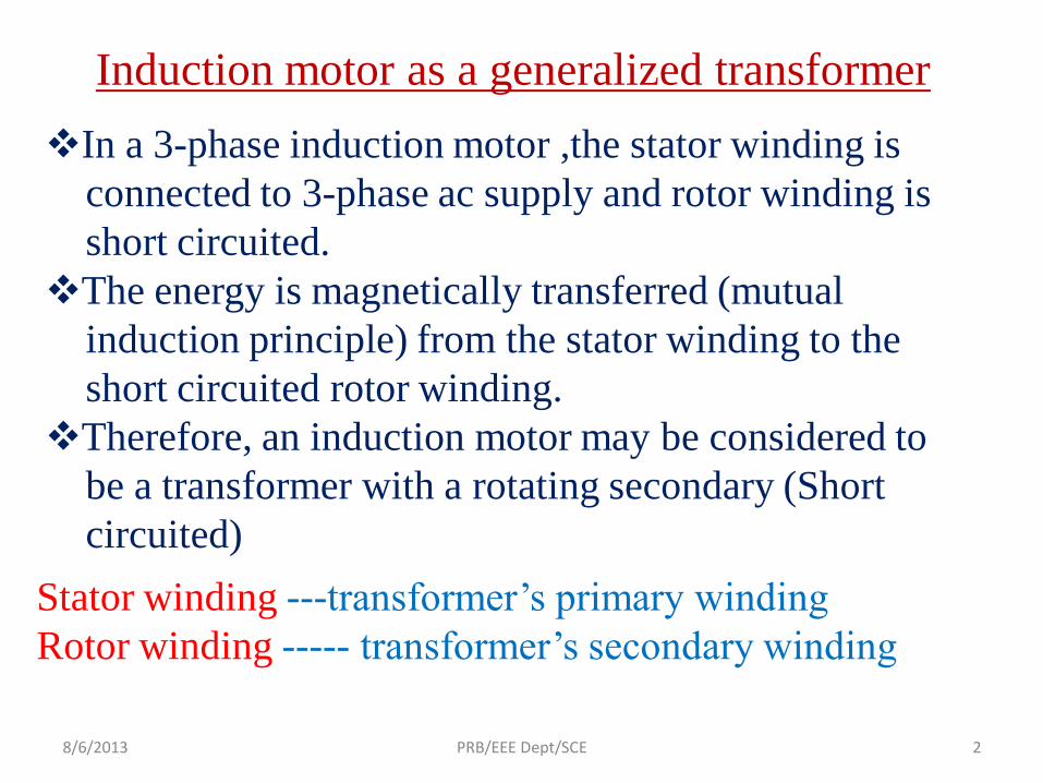
Induction motor as a generalized transformer
In a 3-phase induction motor ,the stator winding is
connected to 3-phase ac supply and rotor winding is
short circuited.
The energy is magnetically transferred (mutual
induction principle) from the stator winding to the
short circuited rotor winding.
Therefore, an induction motor may be considered to
be a transformer with a rotating secondary (Short
circuited)
Stator winding ---transformer’s primary winding
Rotor winding ----- transformer’s secondary winding
8/6/2013 PRB/EEE Dept/SCE

8/6/2013 PRB/EEE Dept/SCE 3
Equivalent circuit of an induction motor in per phase quantity

8/6/2013 PRB/EEE Dept/SCE 4
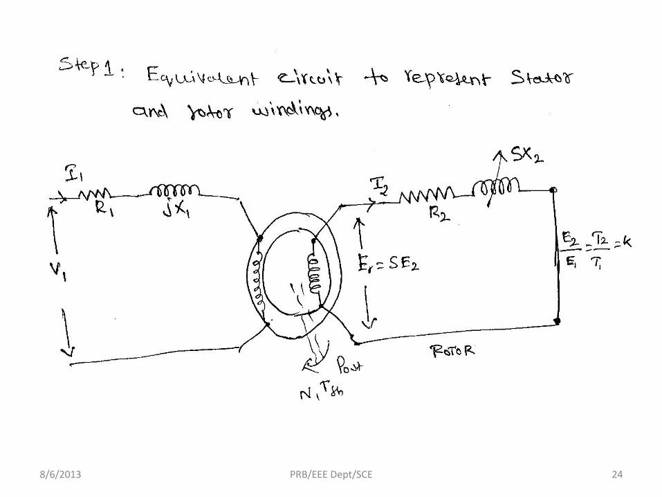
Stator circuit
V1 = applied voltage per phase to the stator
R1, X1 = stator resistance and stator leakage reactance
per phase respectively
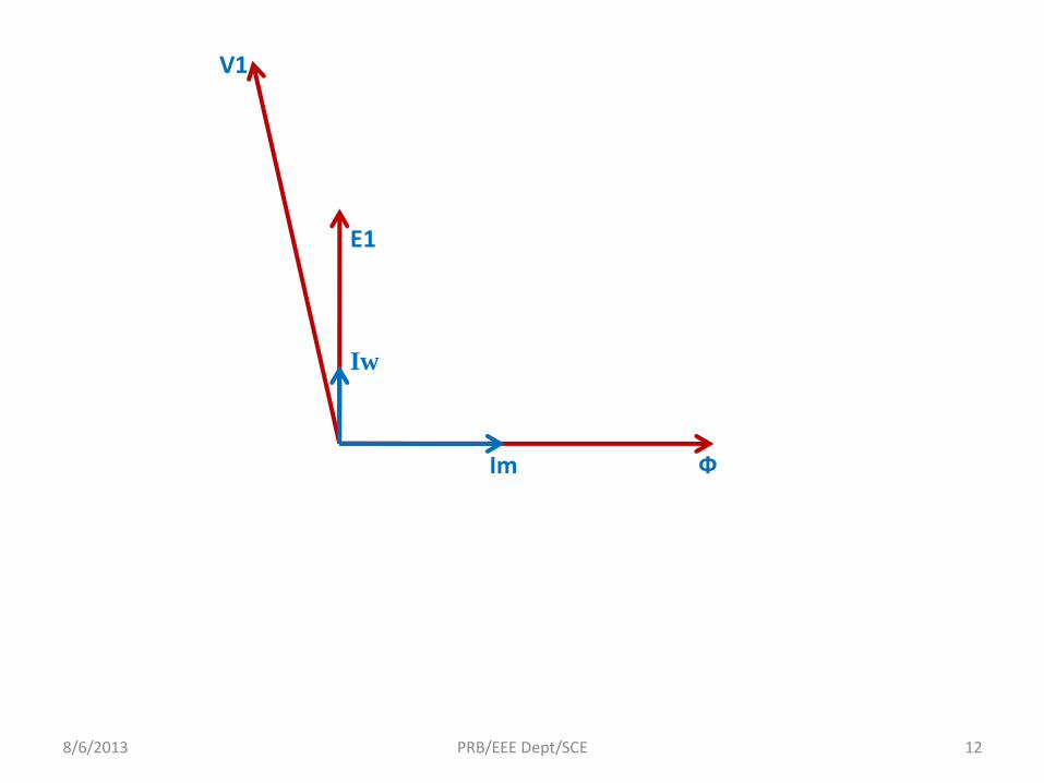
V1→ flux, φ→ links stator and rotor winding → self
induced emf E1 and mutually induced emf
Er =SE2=SKE1
Where, K = transformation ratio
K = (E2/E1) = (T2/T1)
In induction motor
(I1/I2) ≠ K because of distributed winding

8/6/2013 PRB/EEE Dept/SCE 5
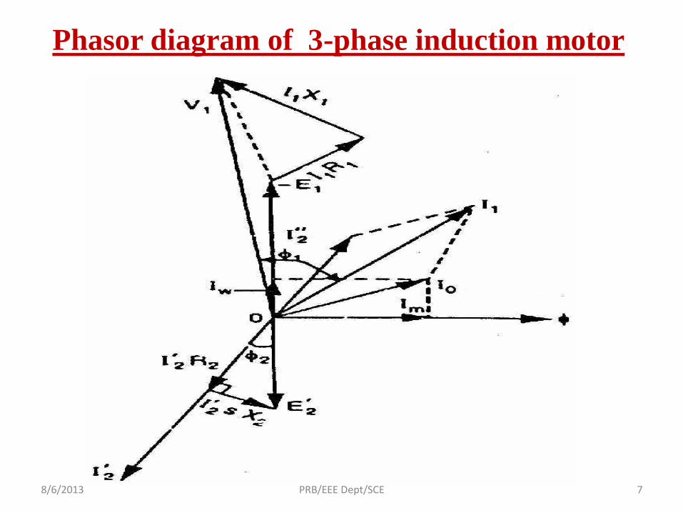
I1 causes voltage drop in R1 and X1
V1 = E1 + I1R1+jX1 ---------------------- phasor sum
When the motor is at no load, the stator winding
draws a current Io
Io = Iw + Im ------------ phasor sum
Iw = working component (no load loss)
Im – magnetizing component (setup flux in the core)

8/6/2013 PRB/EEE Dept/SCE 6
Rotor circuit
R2, X2 = rotor resistance and reactance
SX2= rotor reactance at any slip
Er→ set up I2 in the rotor
Er = I2R2 + jI2SX2 ---------------phasor sum
The rotor current I2 is reflected as I’2 in the stator
I’2 = KI2
I1 = Io + I’2 ------------ phasor sum
7
Phasor diagram of 3-phase induction motor
8/6/2013 PRB/EEE Dept/SCE

8
V1
8/6/2013 PRB/EEE Dept/SCE
9
V1
Ф
8/6/2013 PRB/EEE Dept/SCE

10
V1
Ф
E1
8/6/2013 PRB/EEE Dept/SCE

11
V1
Ф
E1
Im
8/6/2013 PRB/EEE Dept/SCE
12
V1
Ф
E1
Im
Iw
8/6/2013 PRB/EEE Dept/SCE
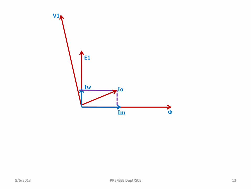
13
V1
Ф
E1
Im
Iw Io
8/6/2013 PRB/EEE Dept/SCE

14
V1
Ф
E1
Im
Iw Io
Er
8/6/2013 PRB/EEE Dept/SCE

15
V1
Ф
E1
Im
Iw Io
Er
I2
8/6/2013 PRB/EEE Dept/SCE

16
V1
Ф
E1
Im
Iw Io
Er
I2
I’2
8/6/2013 PRB/EEE Dept/SCE

17
V1
Ф
E1
Im
Iw Io
Er
I2
I’2 I1
8/6/2013 PRB/EEE Dept/SCE

18
V1
Ф
E1
Im
Iw Io
Er
I2
I’2 I1
I1R1
8/6/2013 PRB/EEE Dept/SCE

19
V1
Ф
E1
Im
Iw Io
Er
I2
I’2 I1
I1R1
I1X1
8/6/2013 PRB/EEE Dept/SCE

20
V1
Ф
E1
Im
Iw Io
Er
I2
I’2 I1
I1R1
I1X1
I2R2
8/6/2013 PRB/EEE Dept/SCE

21
V1
Ф
E1
Im
Iw Io
Er
I2
I’2 I1
I1R1
I1X1
I2R2
I2SX2
8/6/2013 PRB/EEE Dept/SCE
Ф2
Ф1

22
Equivalent circuit of
three-phase induction
motor
8/6/2013 PRB/EEE Dept/SCE
23
The machine parameters can be
represented in an electric circuit is
known as equivalent circuit.
Equivalent circuit
PurposeThe purpose of deriving an equivalent
circuit for a 3-phase induction motor is to
represent it by a simple electric circuit for
easy analysis.8/6/2013 PRB/EEE Dept/SCE
8/6/2013 PRB/EEE Dept/SCE 24

8/6/2013 PRB/EEE Dept/SCE 25

8/6/2013 PRB/EEE Dept/SCE 26

8/6/2013 PRB/EEE Dept/SCE 27
Step 2 : Equivalent circuit to represent stator core

28
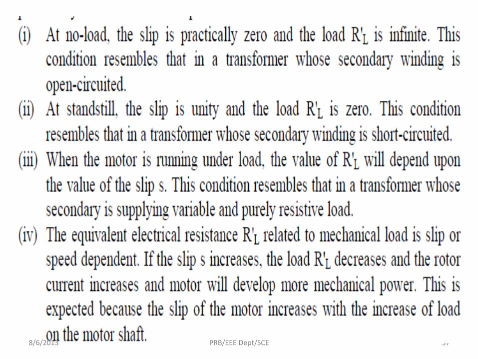
Equivalent circuit of the rotor
In a transformer, secondary is connected to electrical load. But, in a motor, the
rotor drives the mechanical load. Therefore mechanical load of the motor is
replaced by the equivalent electrical load.
Equivalent circuit per phase of the rotor at slip S
8/6/2013 PRB/EEE Dept/SCE
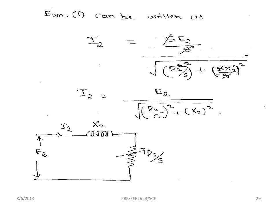
Step 3 : Convert actual rotating circuit into an equivalent stationary rotor circuit
8/6/2013 PRB/EEE Dept/SCE 29

308/6/2013 PRB/EEE Dept/SCE

8/6/2013 PRB/EEE Dept/SCE 31

8/6/2013 PRB/EEE Dept/SCE 32

8/6/2013 PRB/EEE Dept/SCE 33
Exact equivalent circuit
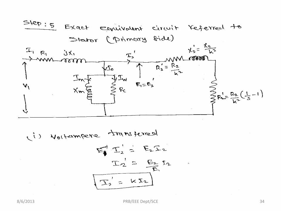
8/6/2013 PRB/EEE Dept/SCE 34

8/6/2013 PRB/EEE Dept/SCE 35
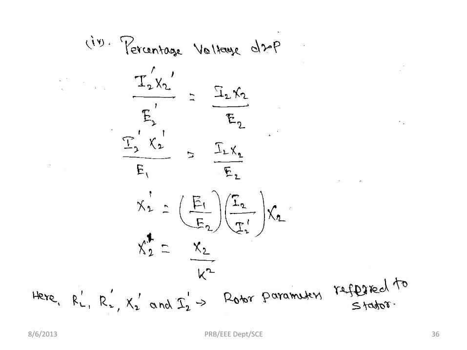
8/6/2013 PRB/EEE Dept/SCE 36
378/6/2013 PRB/EEE Dept/SCE
8/6/2013 PRB/EEE Dept/SCE 38
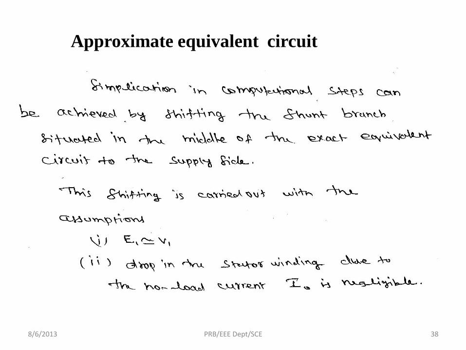
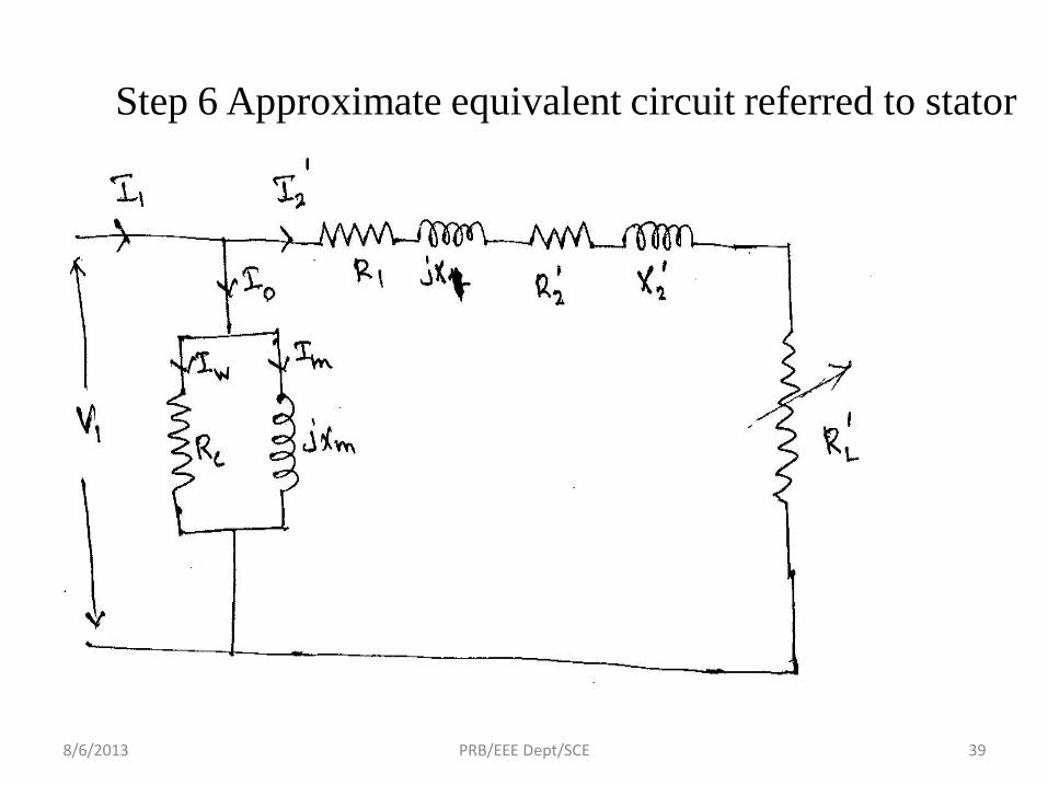
Approximate equivalent circuit
8/6/2013 PRB/EEE Dept/SCE 39
Step 6 Approximate equivalent circuit referred to stator

8/6/2013 PRB/EEE Dept/SCE 40

41
Drawbacks
8/6/2013 PRB/EEE Dept/SCE
8/6/2013 PRB/EEE Dept/SCE 42

8/6/2013 PRB/EEE Dept/SCE 43

8/6/2013 PRB/EEE Dept/SCE 44

8/6/2013 PRB/EEE Dept/SCE 45

8/6/2013 PRB/EEE Dept/SCE 46
8/6/2013 PRB/EEE Dept/SCE 47

8/6/2013 PRB/EEE Dept/SCE 48

8/6/2013 PRB/EEE Dept/SCE 49

8/6/2013 PRB/EEE Dept/SCE 50
8/6/2013 PRB/EEE Dept/SCE 51

8/6/2013 PRB/EEE Dept/SCE 52
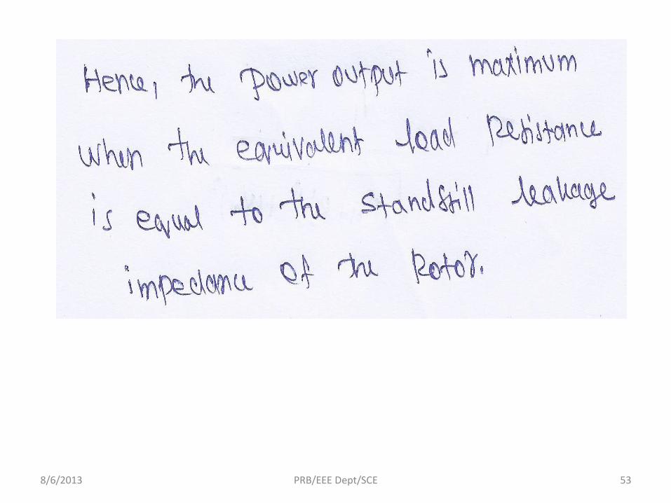
8/6/2013 PRB/EEE Dept/SCE 53

8/6/2013 PRB/EEE Dept/SCE 54

8/6/2013 PRB/EEE Dept/SCE 55
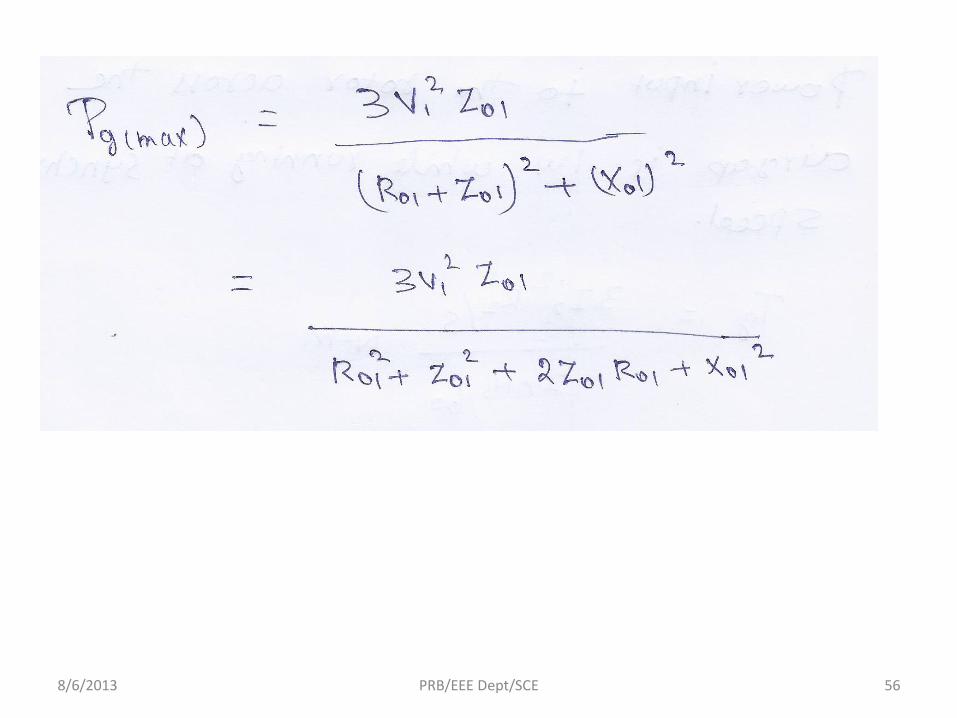
8/6/2013 PRB/EEE Dept/SCE 56

8/6/2013 PRB/EEE Dept/SCE 57
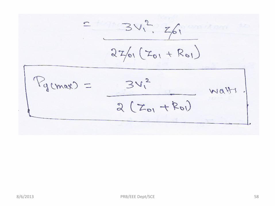
8/6/2013 PRB/EEE Dept/SCE 58

8/6/2013 PRB/EEE Dept/SCE 59
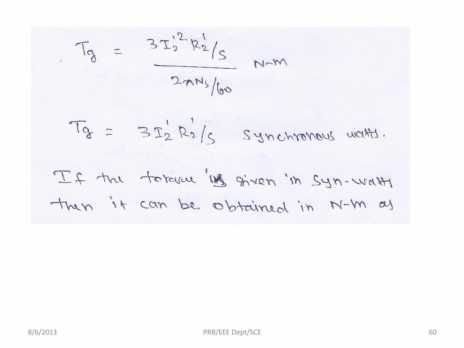
8/6/2013 PRB/EEE Dept/SCE 60

8/6/2013 PRB/EEE Dept/SCE 61


