
Epsilon - MONO Equip manuals/Epsilon... · The EPSILON can be transported ... 10 The bakery manager...
53
FG080 –EPSILON 05-4-17 Rev.B17 OPERATING AND MAINTENANCE MANUAL Epsilon NOTE: THIS MACHINE IS FOR USE WITH SOFT DOUGH ONLY The use of templates and/or accessories not produced or supplied by MONO Equipment will invalidate the machine’s warranty Enter Serial No. here.____________________________ In the event of an enquiry please quote this serial number. www.monoequip.com
Transcript of Epsilon - MONO Equip manuals/Epsilon... · The EPSILON can be transported ... 10 The bakery manager...

FG080 –EPSILON 05-4-17 Rev.B17
OPERATING AND MAINTENANCE MANUAL
Epsilon
DEPOSITOR
NOTE: THIS MACHINE IS FOR USE WITH SOFT DOUGH ONLY
The use of templates and/or accessories not produced or supplied by MONO Equipment will invalidate the machine’s warranty
Enter Serial No. here.____________________________
In the event of an enquiry please quote this serial number.
www.monoequip.com

FG080 –EPSILON 05-4-17 Rev.B17

FG080 –EPSILON 05-4-17 Rev.B17 3
Failure to adhere to the cleaning and maintenance instructions detailed in this booklet
could affect the warranty of this machine.
FOR SAFE WORKING, PAY SPECIAL ATTENTION TO ITEMS MARKED
The use of templates and/or accessories not produced or supplied by MONO Equipment will invalidate the
machine’s warranty

FG080 –EPSILON 05-4-17 Rev.B17 4
CONTENTS 1.0 - INTRODUCTION
2.0 - DIMENSIONS
3.0 - SPECIFICATIONS
4.0 - SAFETY
5.0 - INSTALLATION
6.0 - ISOLATION
7.0 - CLEANING INSTRUCTIONS
8.0 - OPERATING CONDITIONS
9.0 - PREPARING FOR OPERATION
9A – FITTING THE HOPPER
9B – FITTING A TEMPLATE
10.0 - OPERATING INSTRUCTIONS
1 – SELECT PRODUCT TYPE
2 – SELECT SAVED PRODUCT TYPE OR CHOOSE EMPTY SLOT TO CREATE A NEW PROGRAM
3 – OPERATOR SCREEN
4 – EDIT & SAVE SCREEN
4A – TRAY SETUP
5 – COPY
6 – DELETE
7 – PASSWORDS
8 – ENGINEERING SETTINGS
9 – FAULT INFORMATION SCREENS
11.0 - MAINTENANCE
12.0 - SPARES AND SERVICE
13.0 - SPARES LIST
14.0 - ELECTRICAL INFORMATION
EPSILON

FG080 –EPSILON 05-4-17 Rev.B17 5
1.0 INTRODUCTION
EPSILON
As it is our policy to improve our machines continuously, we reserve the right to change specifications without prior notice
SOFT
DOUGH HOPPER
EASY CHANGE
TEMPLATES
TRAVELLING HOPPER SYSTEM
(NO CONVEYOR BELTS)
LOAD FROM THE FRONT
TOUCH SCREEN CONTROL
The ground breaking EPSILON tabletop confectionary depositor requires less than 1 square metre of space to operate.
The unique travelling hopper system removes the need for a conveyor belt which means trays can be loaded and unloaded in the most ergonomically efficient way – directly from the front.
The EPSILON can be transported through a normal doorway and plugged into a standard 13amp socket.
Control is by a user friendly tri-colour touch screen (in 14 languages) and can be used to store up to 96 programs.
Robust stainless steel construction for durability and ease of cleaning.
A matching stainless steel table is also available to make the EPSILON freestanding.

FG080 –EPSILON 05-4-17 Rev.B17 6
2.0 DIMENSIONS
EPSILON
756 951
265
774
548

FG080 –EPSILON 05-4-17 Rev.B17 7
3.0 SPECIFICATIONS MODEL 400 450
(Nom. hopper width (mm))
Weight (with hopper fitted) (Kg) : tba tba
Standard hopper 20 22.5
Capacity (litre) :
Power: Single phase, 13A max load. Suitable for 110v,200v,
220v, 230v, and 240v, 50-60 Hz supply.
MAX RATING 2.5kW single phase fused at 13A
Cycles per minute = Depends on product.
i.e. 5 across 30g drop = 16 per minute.
Max program storage = 96
Number of languages = 14
Noise level = Less than 85dB
Electronics = All microprocessor controlled
NOTE:
The minimum deposit that can be made depends on several factors - recipe, mixing
method, template size, nozzle size and deposit speed.
As a guide the following is the minimum that should be attempted:
Macaroons 6g.
Meringues 3g.
Choux Paste 5g.
Viennese 4g.
Sponge Drops 4g.
SOFT DOUGH
As it is our policy to improve our machines continuously, we reserve the right to change specifications without prior notice
However, consult Mono Equipment if your intended product falls outside the above general machine specification.
EPSILON

FG080 –EPSILON 05-4-17 Rev.B17 8
4.0 SAFETY
1 Never use a machine in a faulty condition and always report any damage.
2 Only trained engineers may remove parts from this machine if a tool is required.
3 Always ensure hands are dry before touching any electrical appliance (including
cable, switch and plug). NEVER move machinery by pulling on the power cords
or cables.
4 Ensure that the floor area around the Epsilon is clean to avoid slipping –
especially if carrying heavy hopper and template components to and from the
machine.
5 All operatives must be fully trained.
Use of the machine can prove dangerous if:
the machine is operated by untrained or unskilled staff
the machine is not used for its intended purpose
the machine is not operated correctly
All safety devices applied to the machine during manufacture and the
operating instructions in this manual are required to operate this machine
safely. The owner and the operator are responsible for operating this machine
safely.
6 People undergoing training on the machine must be under direct supervision.
7 Do not operate the machine with any panels or guards removed.
8 No loose clothing or jewellery should be worn while operating the machine.
9 Switch off power at the mains isolator when machine is not in use and before
carrying out any cleaning or maintenance.
EPSILON

FG080 –EPSILON 05-4-17 Rev.B17 9
10 The bakery manager or the bakery supervisor should carry out daily safety
checks on the machine.
11 Do not operate machine without the hopper template fitted correctly.
12 Due to the essential requirement for handling heavy components during cleaning,
it is recommended that protective footwear be worn when carrying out such
procedures.
CAUTION: The feed hopper and pump assembly can exceed 25kg and will need to be lifted off by two people, or dismantled into smaller components while still on the machine.
ALL CLEANING AND MAINTENANCE OPERATIONS MUST BE MADE WITH MACHINE DISCONNECTED FROM THE
POWER SUPPLY.
EPSILON
FG080 –EPSILON 05-4-17 Rev.B17 10
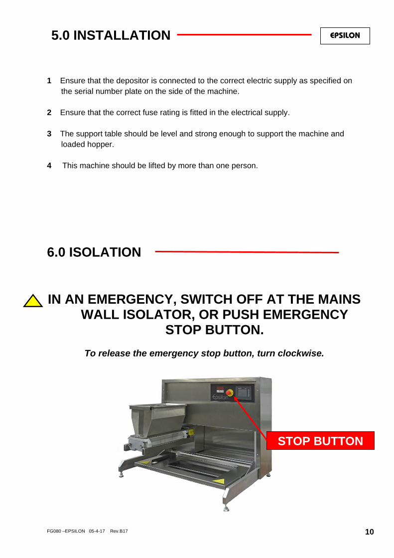
5.0 INSTALLATION
1 Ensure that the depositor is connected to the correct electric supply as specified on
the serial number plate on the side of the machine.
2 Ensure that the correct fuse rating is fitted in the electrical supply.
3 The support table should be level and strong enough to support the machine and
loaded hopper.
4 This machine should be lifted by more than one person.
6.0 ISOLATION
IN AN EMERGENCY, SWITCH OFF AT THE MAINS WALL ISOLATOR, OR PUSH EMERGENCY
STOP BUTTON.
To release the emergency stop button, turn clockwise.
STOP BUTTON
EPSILON

FG080 –EPSILON 05-4-17 Rev.B17 11
7.0 CLEANING INSTRUCTIONS
NOTE:
- Cleaning must be carried out by fully trained personnel only.
- Isolate machine from mains supply before carrying out any cleaning.
- Do not steam clean or use a jet of water.
-Do not use any form of caustic detergent or abrasive cleaners.-
All the outer surfaces of the machine should be wiped over daily with warm soapy water.
DOUGH HOPPERS BETWEEN PRODUCT MIX CHANGES
The feed hopper, pump assembly, template, nozzles etc. should be removed from
the machine and dismantled for thorough cleaning between product mix changes.
1. Open top safety guard (lift front and unhook the back edge) and remove excess
mixture remaining in the feed hopper.
2. Slacken template clamp strip nuts and remove fitted template from pump assembly
by sliding out while supporting it to avoid damage.
NOTE.
Thumbscrews only need to be released slightly to allow the template to slide away
from the pump assembly. If loosened too much, the template will have to be supported.
TEMPLATE
DOUGH HOPPER
EPSILON
CLAMP STRIP AND NUTS
NOZZLES

FG080 –EPSILON 05-4-17 Rev.B17 12
3 To reduce weight and bulk, separate and remove the empty feed hopper from the
pump assembly, by unscrewing the wing nuts, whilst still on the machine,.
To gain access to the inner wing nut, slide the complete hopper away from the machine
body slightly (keep on support bars) - this will also disengage the pump assembly from
the drive shaft.
Ensure that the wing nuts are placed where they will not be lost.
HOPPER WINGNUTS
FG080 –EPSILON 05-4-17 Rev.B17 13
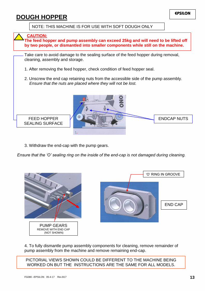
CAUTION:
The feed hopper and pump assembly can exceed 25kg and will need to be lifted off by two people, or dismantled into smaller components while still on the machine. Take care to avoid damage to the sealing surface of the feed hopper during removal, cleaning, assembly and storage. 1. After removing the feed hopper, check condition of feed hopper seal. 2. Unscrew the end cap retaining nuts from the accessible side of the pump assembly.
Ensure that the nuts are placed where they will not be lost. 3. Withdraw the end-cap with the pump gears.
Ensure that the ‘O’ sealing ring on the inside of the end-cap is not damaged during cleaning.
4. To fully dismantle pump assembly components for cleaning, remove remainder of pump assembly from the machine and remove remaining end-cap.
ENDCAP NUTS
END CAP
‘O’ RING IN GROOVE
FEED HOPPER SEALING SURFACE
DOUGH HOPPER
PUMP GEARS REMOVE WITH END CAP
(NOT SHOWN)
PICTORIAL VIEWS SHOWN COULD BE DIFFERENT TO THE MACHINE BEING WORKED ON BUT THE INSTRUCTIONS ARE THE SAME FOR ALL MODELS.
EPSILON
NOTE: THIS MACHINE IS FOR USE WITH SOFT DOUGH ONLY

FG080 –EPSILON 05-4-17 Rev.B17 14
EPSILON
To remove the table for cleaning: 1. Push the table down to its lowest level. 2. Lift the front edge and lift the table towards you. The table will release from the back pins and can be placed in a washer for cleaning.
To replace the table after cleaning: 1. Hold table with the front edge raised and engage the slots over the pin on both sides. 2. Lower the table front edge. When in the correct position the table will not slide forward.
TABLE
LOCATING PIN
FG080 –EPSILON 05-4-17 Rev.B17 15
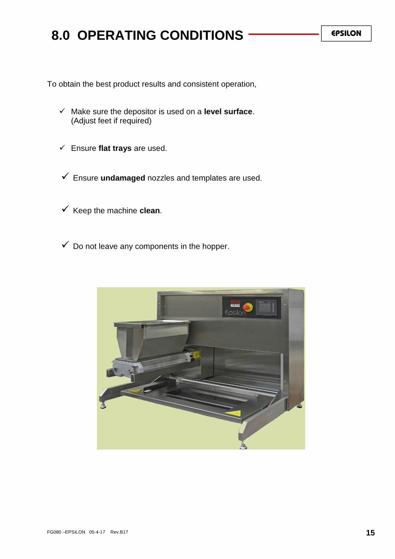
8.0 OPERATING CONDITIONS To obtain the best product results and consistent operation,
Make sure the depositor is used on a level surface. (Adjust feet if required)
Ensure flat trays are used.
Ensure undamaged nozzles and templates are used.
Keep the machine clean. Do not leave any components in the hopper.
EPSILON

FG080 –EPSILON 05-4-17 Rev.B17 16
9.0 PREPARING FOR OPERATION
1 Select template and nozzles required and fit as section 9a & 9b following.
Fill hopper with mix and close hopper guard.
2 Connect power cable to the correct electrical supply.
Make sure stop button is in released position (turn clockwise if required).
3 Select an existing program or create a new program through the on-screen menus.
(see section 10 operation)
4 The machine is now ready for operation.
TEMPLATE
HOPPER
REMOVE GUARD TO FILL HOPPER.
REPLACE CORRECTLY. (MACHINE WILL NOT OPERATE WITHOUT
THIS GUARD IN POSITION) SCREEN
STOP BUTTON
It is recommended that when heavy mixes are used, the inside of the hopper should be coated with vegetable oil and for lighter mixes such as meringue, dampen with water. The oil or water will help the mix to settle down the hopper walls and prevent air being sucked in.
EPSILON
NOTE: THIS MACHINE IS FOR USE WITH SOFT DOUGH ONLY
The use of templates and/or accessories not produced or supplied by MONO Equipment will invalidate the machine’s warranty

FG080 –EPSILON 05-4-17 Rev.B17 17
TABLE ADJUSTMENTS It is important that the table is parallel with the hopper. (If this is not correct the nozzles will not be the same distance from the trays and the deposits will differ across the tray). Measure the distance at “A” and “B” below and check that they are the same. This should be checked with the hopper bars positioned at both the full left position and the full right position.
If not the same, an adjustment can be made by raising or lowering the adjusters under the table. There is one each side to allow the table to be adjusted evenly.
Lift the front edge of the table and, with a suitable spanner, release the locking nut. screw the adjuster bolt up or down and then lock it in position with the locking nut. TRAY GUIDE ADJUSTMENT
“A”
“B”
This allows different width trays to be accommodated. To adjust the position of the back guide, remove the table and turn it over. Loosen the thumb nuts and slide the sheet across to the desired position. Tighten the nuts and replace the table.
NUTS
EPSILON
FG080 –EPSILON 05-4-17 Rev.B17 18
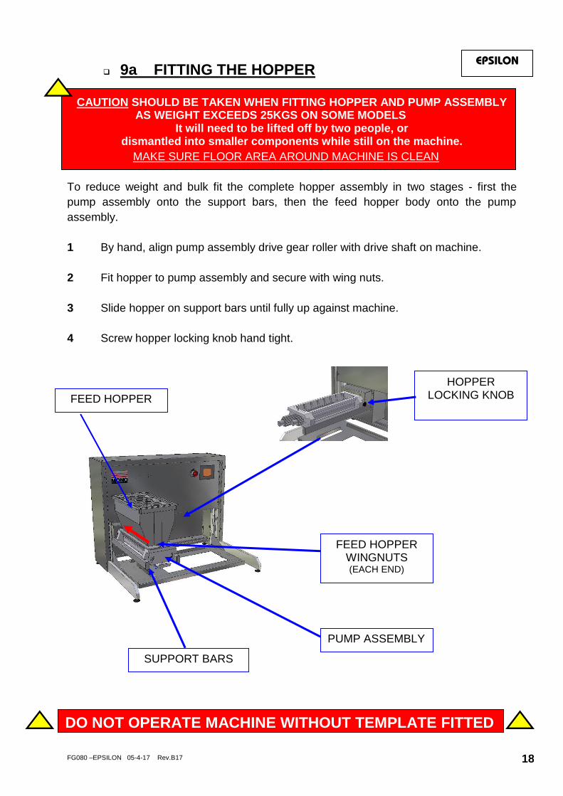
9a FITTING THE HOPPER
CAUTION SHOULD BE TAKEN WHEN FITTING HOPPER AND PUMP ASSEMBLY AS WEIGHT EXCEEDS 25KGS ON SOME MODELS
It will need to be lifted off by two people, or dismantled into smaller components while still on the machine.
MAKE SURE FLOOR AREA AROUND MACHINE IS CLEAN
To reduce weight and bulk fit the complete hopper assembly in two stages - first the
pump assembly onto the support bars, then the feed hopper body onto the pump
assembly.
1 By hand, align pump assembly drive gear roller with drive shaft on machine.
2 Fit hopper to pump assembly and secure with wing nuts.
3 Slide hopper on support bars until fully up against machine.
4 Screw hopper locking knob hand tight.
PUMP ASSEMBLY
FEED HOPPER
DO NOT OPERATE MACHINE WITHOUT TEMPLATE FITTED
FEED HOPPER WINGNUTS (EACH END)
SUPPORT BARS
HOPPER LOCKING KNOB
EPSILON

FG080 –EPSILON 05-4-17 Rev.B17
9b FITTING A TEMPLATE
1 Select template and nozzles required.
(Nozzles are not required for sheeting, staggered or stub templates)
2 Attach nozzles to template body:
3 Slide template into matching recess at base of pump assembly until the stop is in
position.
4 Tighten nuts on clamp strip (on underside of pump assembly) to secure template.
NOTE. If the nuts are not securely tightened,
leakage of mix will occur, affecting deposit weights.
TEMPLATE BODY
NOZZLES CLAMP STRIP NUTS
DO NOT OPERATE MACHINE WITHOUT TEMPLATE FITTED
EPSILON

FG080 –EPSILON 05-4-17 Rev.B17 20
10.0 ‘Epsilon’ OPERATION EPSILON
ALL OPERATIONS ARE ACTIVATED BY TOUCHING AREAS ON THE SCREEN WITH A FINGER. DO NOT USE EXCESSIVE FORCE OR HARD OBJECTS AS THIS WILL INVALIDATE MACHINE WARRANTY.

FG080 –EPSILON 05-4-17 Rev.B17 21
=
KEYBOARD ENTRY
REQUIRED
BLUE = OPERATION
RED = CHANGE SETTINGS
OPERATING KEY
FOR FOLLOWING INSTRUCTIONS
FOLLOW BLUE ARROWS AND BOXES TO OPERATE THE DEPOSITOR WITH ALREADY
SAVED PROGRAMS
FOLLOW RED ARROWS AND BOXES TO CHANGE SETTINGS AND CREATE NEW
PROGRAMS
WHEN KEYBOARD APPEARS, A CODE MUST BE ENTERED BY TOUCHING THE
NUMBERS IN THE CORRECT ORDER
IF A GREY BOX IS SHOWN IN THE BUTTON DESCRIPTION e.g. GO TO THE CORRESPONDING PAGE FURTHER ON IN THE INSTRUCTIONS. (MARKED IN TOP RIGHT HAND CORNER OF EACH PAGE)
7

FG080 –EPSILON 05-4-17 Rev.B17 22
SELECT PRODUCT TYPE SELECT PRODUCT TO DEPOSIT OR TO CREATE NEW PROGRAM
STRIP SHEETING
DROP
CHOOSE LANGUAGE MACHINE SETUP PRODUCT
EDITING COPYING DELETING
PROGRESS TO NEXT SCREEN
PASSWORDS ARE REQUIRED FOR
THESE FUNCTIONS. SEE PART 7
TO LAST SCREEN
TOWER
1
TOUCH THE SCREEN FOR THE TYPE OF PRODUCT REQUIRED THEN TOUCH TO MOVE TO THE NEXT SCREEN
HIGHLIGHT BOX APPEARS TO SHOW
SELECTED PRODUCT WHEN SCREEN IS
TOUCHED
THESE BUTTONS CONTROL CHANGES
TO THE MACHINE
PART
ALL OPERATIONS ARE ACTIVATED BY TOUCHING AREAS ON THE SCREEN WITH A FINGER. DO NOT USE EXCESSIVE FORCE OR HARD OBJECTS AS THIS WILL INVALIDATE MACHINE WARRANTY.
FG080 –EPSILON 05-4-17 Rev.B17 23
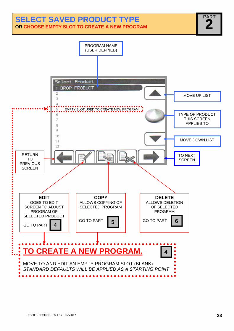
SELECT SAVED PRODUCT TYPE OR CHOOSE EMPTY SLOT TO CREATE A NEW PROGRAM
MOVE UP LIST
TYPE OF PRODUCT THIS SCREEN APPLIES TO
MOVE DOWN LIST
COPY ALLOWS COPYING OF SELECTED PROGRAM
GO TO PART
TO NEXT SCREEN
EDIT GOES TO EDIT
SCREEN TO ADJUST PROGRAM OF
SELECTED PRODUCT GO TO PART
DELETE
ALLOWS DELETION OF SELECTED
PROGRAM
GO TO PART
PROGRAM NAME (USER DEFINED)
4 5 6
2
EMPTY SLOT USED TO CREATE NEW PROGRAM
RETURN TO
PREVIOUSSCREEN
TO CREATE A NEW PROGRAM. MOVE TO AND EDIT AN EMPTY PROGRAM SLOT (BLANK). STANDARD DEFAULTS WILL BE APPLIED AS A STARTING POINT
4
PART

FG080 –EPSILON 05-4-17 Rev.B17 24
OPERATOR SCREEN
PRIME PUMP
USE THIS TO GET A CONSISTANT FLOW
OF MIX.
WEIGHT VALUE ADJUSTMENT
WEIGHT VALUE
PROGRAM NAME
3
THIS SCREEN CONTROLS THE ACTIONS REQUIRED BY THE OPERATOR.
RETURN TO PREVIOUS SCREEN
START STOP
PART

FG080 –EPSILON 05-4-17 Rev.B17 25
EDIT AND SAVE SCREEN
4 PROGRAM NAME
MUST BE ENTERED TO
ALLOW PROGRAM TO SAVE
PRODUCT QUANTITY THIS IS A SETTING NUMBER AND
DOES NOT INDICATE A MEASURE OF
ACTUAL VOLUME
SUCK BACK QUANTITY
TABLE JOG DISTANCE (mm)
OVERALL MACHINE SPEED (% OF MAXIMUM)
SAVE EDITS
EXIT THIS SCREEN
ENTER TRAY
SETUP SCREEN
PRIME PUMP
START MANUAL MODE
GO TO PART
4A
EXAMPLE:
DROP
SETTING ERROR INDICATOR
NOZZLE HEIGHT ABOVE TRAY
SURFACE
NOZZLE HEIGHT ABOVE TRAY SURFACE AND THE JOG DISTANCE IS OVER 80mm THIS
ERROR SCREEN WILL SHOW. RESET TO LOWER FIGURES TO CONTINUE.
PART

FG080 –EPSILON 05-4-17 Rev.B17 26
EXAMPLE:
TOWER
NOZZLE HEIGHT (mm) FOR EACH LAYER
NOZZLE HEIGHT (mm) FROM TRAY SURFACE
DEPOSIT QUANTITY FOR EACH LAYER
0 OTHER SETTING BUTTONS ARE THE SAME AS THE PREVIOUS PAGE
EXAMPLE:
STRIP
DEPOSIT QUANTITY FOR BEGINNING OF
PRODUCT
DEPOSIT QUANTITY FOR LENGTH
DEPOSIT QUANTITY FOR END OF
PRODUCT (-VE VALUES POSSIBLE)
NOZZLE HEIGHT ABOVE TRAY
SURFACE LENGTH (mm) OF
DEPOSIT
OTHER SETTING BUTTONS ARE THE SAME AS THE PREVIOUS PAGE

FG080 –EPSILON 05-4-17 Rev.B17 27
EXAMPLE:
SHEETING
DEPOSIT QUANTITY FOR BEGINNING OF
PRODUCT
DEPOSIT QUANTITY FOR LENGTH
DEPOSIT QUANTITY FOR END OF
PRODUCT (-VE VALUES POSSIBLE)
NOZZLE HEIGHT ABOVE TRAY
SURFACE LENGTH (mm) OF
DEPOSIT
OTHER SETTING BUTTONS ARE THE SAME AS THE PREVIOUS PAGE

FG080 –EPSILON 05-4-17 Rev.B17 28
TRAY SETUP
4A
DISTANCE (mm) TO 1ST
ROW ON TRAY (WHEN USING MANUAL OVER-RIDE)
DISTANCE (mm) BETWEEN ROWS (WHEN USING MANUAL OVER-RIDE)
MANUAL OVER-RIDE FOR ROW SPACING
ON/OFF
TRAY EDGE
HEIGHT (mm)
HORIZONTAL DISTANCE MOVED BY HOPPER AFTER
DEPOSIT
PRODUCT TYPE TO PREVIOUS SCREEN
NUMBER OF ROWS PER
TRAY
TRAY LENGTH (mm)
PRESS WINDOWS AND ENTER VALUES VIA KEYPAD
VERTICAL DISTANCE MOVED BY HOPPER AFTER
DEPOSIT
WIPE BACK
DEPOSIT DIRECTION
TOGGLES BETWEEN TWO WAY (DEFAULT) OR
ONE WAY
PART
FG080 –EPSILON 05-4-17 Rev.B17 29
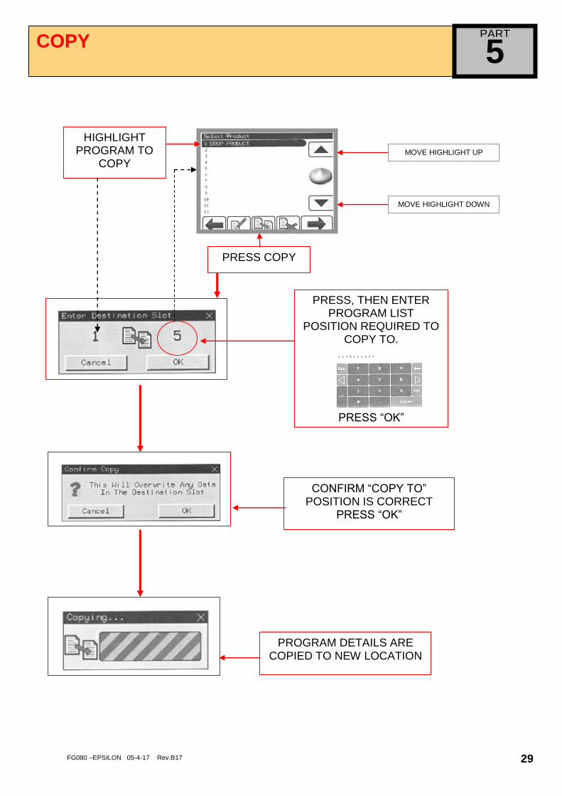
COPY
PRESS, THEN ENTER PROGRAM LIST
POSITION REQUIRED TO COPY TO.
PRESS “OK”
5
HIGHLIGHT PROGRAM TO
COPY
PRESS COPY
CONFIRM “COPY TO” POSITION IS CORRECT
PRESS “OK”
PROGRAM DETAILS ARE COPIED TO NEW LOCATION
MOVE HIGHLIGHT UP
MOVE HIGHLIGHT DOWN
PART

FG080 –EPSILON 05-4-17 Rev.B17 30
DELETE 6
HIGHLIGHT PROGRAM TO
DELETE
PRESS DELETE
MOVE HIGHLIGHT UP
MOVE HIGHLIGHT DOWN
TO CONFIRM, “DELETE” IS CORRECT PRESS “OK”
PROGRAM DETAILS ARE DELETED
CAUTION DO NOT ATTEMPT TO DELETE, UNLESS YOU ARE FULLY AWARE OF
THE RESULTS
PART

FG080 –EPSILON 05-4-17 Rev.B17 31
PASSWORDS
7
561234
3142–ENGINEERING SETTINGS
2808--DIAGNOSTICS
01554777460
RESET FACTORY DEFAULTS
CHANGE EDIT/COPY PASSWORD
CHANGE EDIT/COPY/DELETE
PASSWORD
5
6
1234 – SCREEN ADJUSTMENT
OR
OR
OR
FINE / C0ARSE
8
THIS SECTION IS FOR TRAINED ENGINEERS ONLY
THIS SECTION IS FOR TRAINED ENGINEERS ONLY
THIS SECTION IS FOR TRAINED ENGINEERS ONLY
5
6
4
CAUTION DO NOT ATTEMPT TO MAKE ADJUSTMENTS UNLESS YOU ARE FULLY
AWARE OF THE RESULTS
1111 2222
EDIT/COPY EDIT/COPY DELETE
PART

FG080 –EPSILON 05-4-17 Rev.B17 32
ENGINEERING SETTINGS (1) 8/1
GO TO NEXT SCREEN ENGINEERING SETTING 2
(NEXT PAGE)
EXIT THIS SCREEN
DEFAULT ACCELERATION
FOR PUMP
DEFAULT ACCELERATION
FOR JOG
PUMP SPEED WHEN USING
PRIME BUTTON
DEFAULT JOG SPEED
(VERTICAL AFTER DEPOSIT)
DEFAULT SPEED OF PUMP (100% VALUE IN PRODUCT SETUP PROGRAM)
THIS SECTION IS FOR TRAINED ENGINEERS ONLY
CAUTION DO NOT ATTEMPT TO MAKE ADJUSTMENTS UNLESS YOU ARE
FULLY AWARE OF THE RESULTS
PART
FG080 –EPSILON 05-4-17 Rev.B17 33
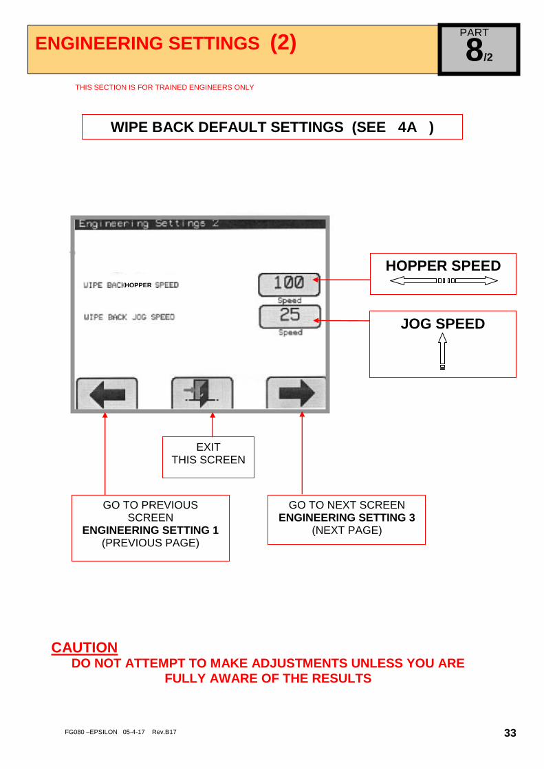
ENGINEERING SETTINGS (2) 8/2
THIS SECTION IS FOR TRAINED ENGINEERS ONLY
CAUTION DO NOT ATTEMPT TO MAKE ADJUSTMENTS UNLESS YOU ARE
FULLY AWARE OF THE RESULTS
HOPPER SPEED
JOG SPEED
EXIT THIS SCREEN
GO TO PREVIOUS SCREEN
ENGINEERING SETTING 1 (PREVIOUS PAGE)
WIPE BACK DEFAULT SETTINGS (SEE 4A )
HOPPER
GO TO NEXT SCREEN ENGINEERING SETTING 3
(NEXT PAGE)
PART

FG080 –EPSILON 05-4-17 Rev.B17 34
ENGINEERING SETTINGS (3)
8/3
THIS SECTION IS FOR TRAINED ENGINEERS ONLY
PUMP
TRAY
JOG
GEARBOX RATIOS
EXIT THIS SCREEN
GO TO PREVIOUS SCREEN ENGINEERING SETTING 2
(PREVIOUS PAGE)
CAUTION DO NOT ATTEMPT TO MAKE ADJUSTMENTS UNLESS YOU ARE
FULLY AWARE OF THE RESULTS
PART
FG080 –EPSILON 05-4-17 Rev.B17 35
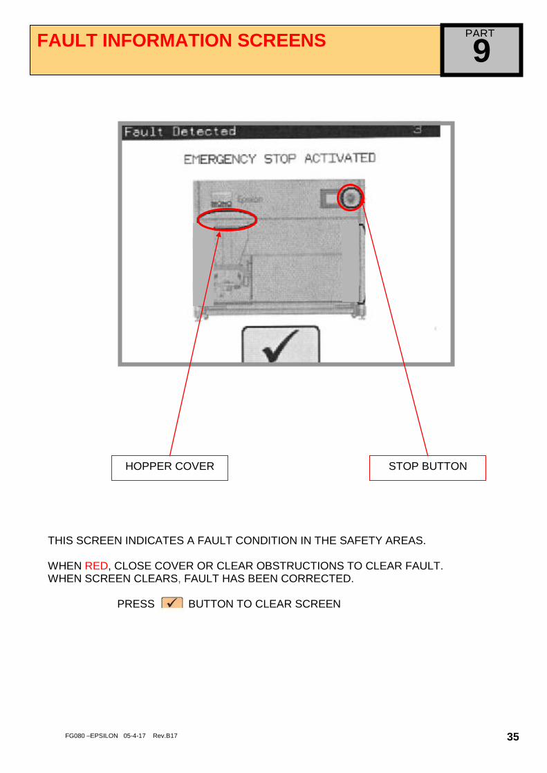
FAULT INFORMATION SCREENS
9
HOPPER COVER STOP BUTTON
THIS SCREEN INDICATES A FAULT CONDITION IN THE SAFETY AREAS. WHEN RED, CLOSE COVER OR CLEAR OBSTRUCTIONS TO CLEAR FAULT. WHEN SCREEN CLEARS, FAULT HAS BEEN CORRECTED.
PRESS BUTTON TO CLEAR SCREEN
PART

FG080 –EPSILON 05-4-17 Rev.B17 36
IF THE FOLLOWING SCREEN APPEARS, CHECK THAT THE HOOPER MOVEMENT ETC. IS NOT JAMMED WITH SOMETHING. IF IT IS, CLEAR THE OBSTRUCTION AND PRESS TO PROCEED.
IF THE FAULT IS NOT OBVIOUS AND NOT ABLE TO BE CLEARED SAFELY, A SUITABLY TRAINED ENGINEER SHOULD BE CALLED
ERROR WHEN LOADING/SAVING RECIPE DATA TO HMI STORAGE CARD
PLEASE CONTACT SERVICE DEPT. / ENGINEER IF PROBLEM PERSISTS

FG080 –EPSILON 05-4-17 Rev.B17 37
11.0 MAINTENANCE
Under most conditions the machine only needs to be kept clean and used as
instructed in this manual.
WARNING: DO NOT UNDER ANY CIRCUMSTANCES USE A WATER HOSE OR PRESSURE WASHER TO
CLEAN THIS MACHINE.
EPSILON

FG080 –EPSILON 05-4-17 Rev.B17 38
12.0 SPARES AND SERVICE
.
If a fault arises, please do not hesitate to contact the
Customer Service Department, quoting the machine serial number
on the silver information plate of the machine and on the front cover of this manual
UK SERVICE, SPARES and OVERSEAS SUPPORT:
Queensway Swansea West Industrial Estate
Swansea. SA5 4EB UK
email:[email protected] SPARES TEL. +44(0)1792 564039
Web site:www.monoequip.com
Tel. 01792 561234
Fax. 01792 561016
EPSILON

FG080 –EPSILON 05-4-17 Rev.B17 39
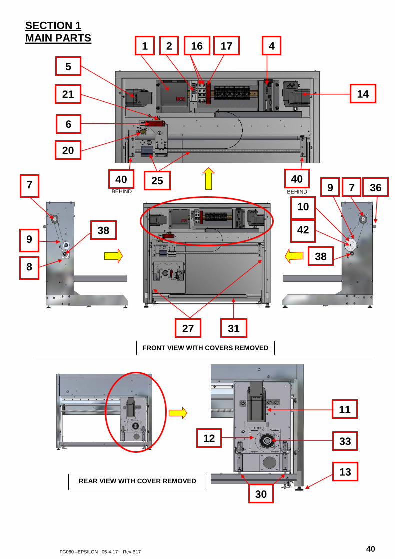
13.0 SPARES
EPSILON
EPSILON
FG080 –EPSILON 05-4-17 Rev.B17 40
14
4 17 2 1
5
6
7
9
8
10
9 7
11
FRONT VIEW WITH COVERS REMOVED
REAR VIEW WITH COVER REMOVED
SECTION 1
MAIN PARTS
13
16
25
21
20
27 31
42 38
38
36
12 33
30
40 40 BEHIND BEHIND
FG080 –EPSILON 05-4-17 Rev.B17 41
39
35
42
22
24
23
32
41
28
29
28
37
26
18/19 15
FRONT VIEW WITH COVERS ON
10
34
3
40

FG080 –EPSILON 05-4-17 Rev.B17 42
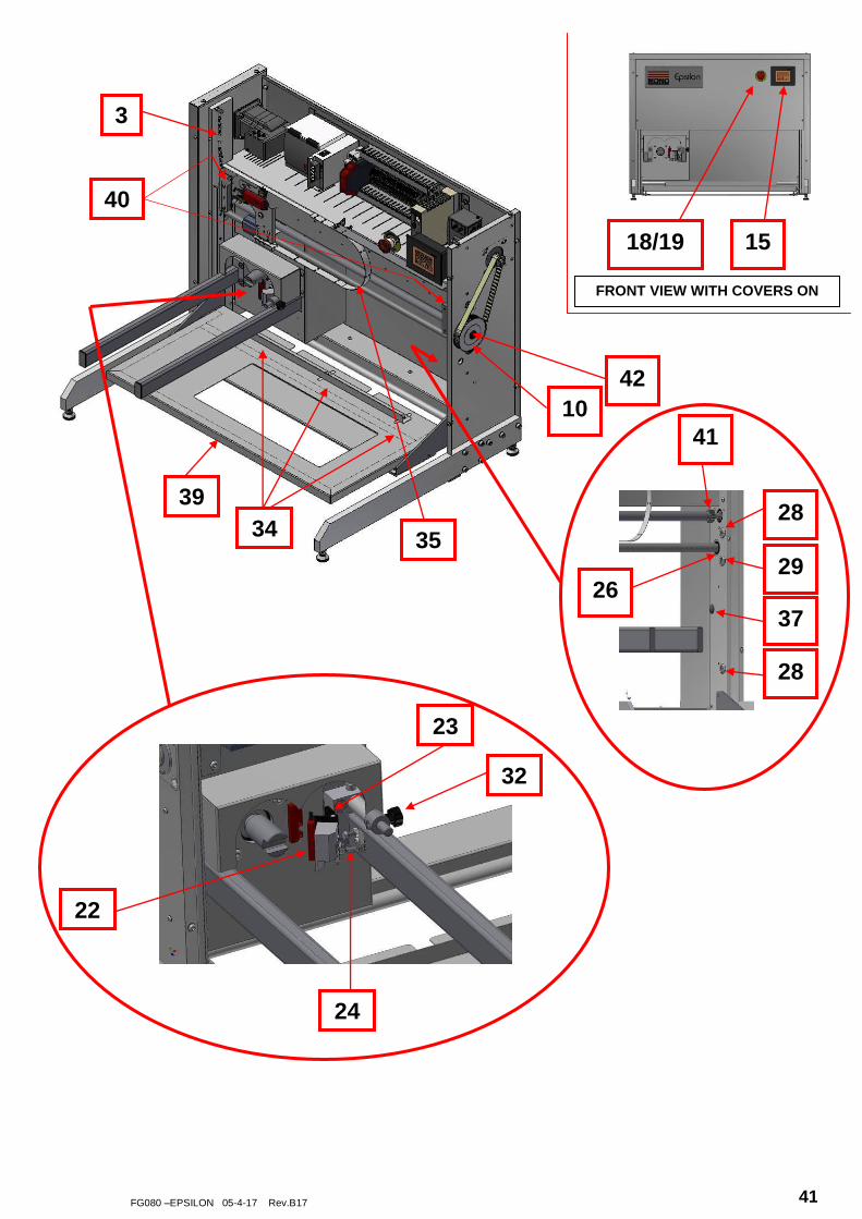
PARTS LIST FOR ITEMS ON PREVIOUS PAGES
1. POWER SUPPLY B801-93-019
2. POWER SUPPLY B801-93-005
3. TRAY SPRING A900-19-097
4. LMC20 B801-80-033
5. TRAY MOTOR B781-74-007
6. SAFETY SWITCH B801-07-005
7. TIMING PULLEY 080-02-00026
8. TIMING PULLEY 080-02-00020
9. TIMING BELT A900-21-107
10. TIMING PULLEY 080-02-00021
11. DEPOSIT MOTOR B781-74-008
12. GEARBOX A900-11-095
13. ADJUSTABLE FOOT A900-27-227
14. JOG MOTOR B781-74-006
15. HMI B801-93-034
16. CIRCUIT BREAKER B872-22-003
17. E-STOP RELAY B801-11-019
18. STOP BUTTON B801-12-043
19. CONTACT BLOCK B801-14-008 (N/C), B801-14-004 (N/O)
20. JOG SWITCH B842-07-029
21. TRAY SWITCH B842-07-030
ITEM DESCRIPTION PART NUMBER

FG080 –EPSILON 05-4-17 Rev.B17 43
22. TEMPLATE SAFETY SWITCH/MAGNET B801-07-006
23. HINGE FOR TEMPLATE SAFETY MAGNET A900-27-217
24. RETURN SPRING A900-19-094
25. BALLSCREW + NUT 080-02-00025 (400 model)
080-02-00048 (450 model)
26. BEARING FOR BALLSCREW A900-06-009
27. VERTICAL SLIDES A900-31-054
28. V-ROLLER – CONCENTRIC A900-06-297
29. V-ROLLER – ECCENTRIC A900-06-298
30. TRACK ROLLER A900-06-136
31. TRAY BACK STOP 080-08-00015(450 model)
080-08-00016 (450 model)
32. HOPPER LOCKING THUMSCREW A900-27-213
33. CIRCLIP – HOPPER DRIVESHAFT A900-01-193
34. WINGNUT FOR TRAY GUIDE A900-04-043
35. CABLE GUIDE STRAP 080-25-00006
36. MAINS CABLE GLANDS B900-17-002
37. BUMP STOPS A900-18-006
38. CIRCLIPS – BALLSCREW A900-01-112
39. PLATFORM FABRICATION 080-08-00001(400 model)
080-08-00011(450 model)
40. RACK 080-02-00032
41. PINION 080-02-00032
42. TRANS-TORQUE BUSH A900-10-01

FG080 –EPSILON 05-4-17 Rev.B17 44
SECTION 2 DOUGH HOPPER PARTS
WINGNUT A900-04-147
END CAP ASSEMBLY DRIVE END
ASSEMBLY No. M073-KMX001
HOPPER FABRICATION 400mm -- M080-09-00008 450mm -- M080-09-00011
WINGNUT A900-04-147
HOPPER SEAL 400mm -- A900-12-083 450mm -- A900-12-084
TOP COVER 400mm -- M080-09-00010 450mm -- M080-09-00014
END CAP BUSH M073-09-00600
END CAP SEAL A900-12-074
DRIVE GEAR
M073-09-00700 (400mm)
M073-09-01600 (450mm)
DRIVEN GEAR
M073-09-00702 (400mm)
M073-09-01602 (450mm)
END CAP ASSEMBLY NON DRIVE END
ASSEMBLY No. M073-KMX002
END CAP M073-09-00500
END CAP BUSH M073-09-00600
END CAP M073-09-03200
FG080 –EPSILON 05-4-17 Rev.B17 45
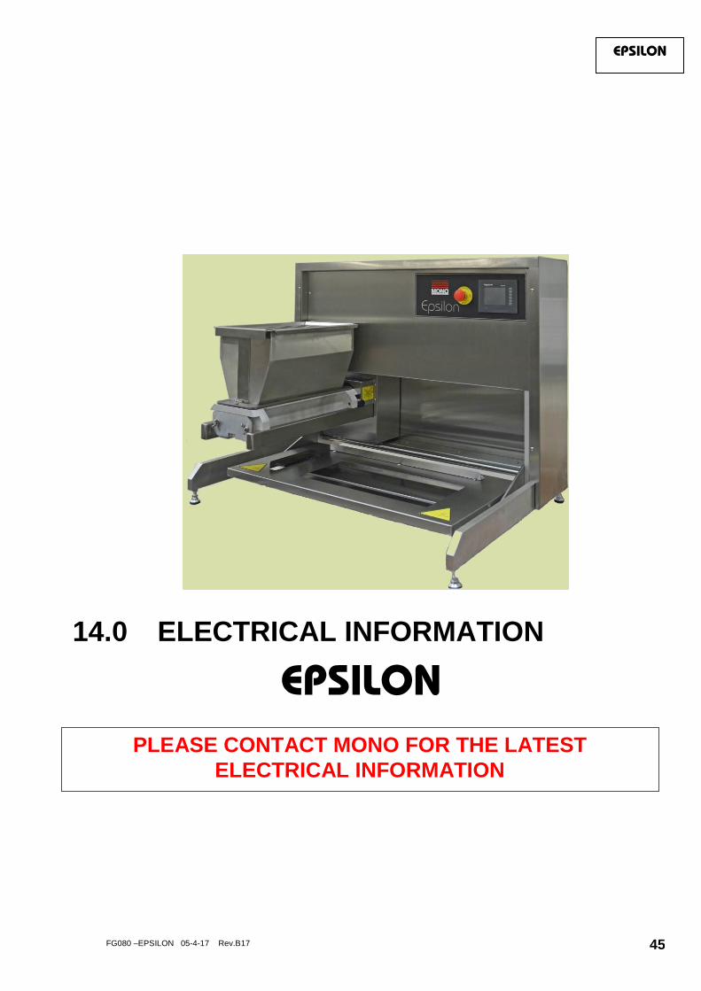
14.0 ELECTRICAL INFORMATION
EPSILON
EPSILON
PLEASE CONTACT MONO FOR THE LATEST
ELECTRICAL INFORMATION

FG080 –EPSILON 05-4-17 Rev.B17 46

FG080 –EPSILON 05-4-17 Rev.B17 47

FG080 –EPSILON 05-4-17 Rev.B17 48

FG080 –EPSILON 05-4-17 Rev.B17 49

FG080 –EPSILON 05-4-17 Rev.B17 50

FG080 –EPSILON 05-4-17 Rev.B17 51

FG080 –EPSILON 05-4-17 Rev.B17 52

FG080 –EPSILON 05-4-17 Rev.B17 53
The equipment mentioned in this manual has CE accreditation.
Queensway Swansea West Industrial Estate
Swansea. SA5 4EB UK
Tel. +44(0)1792 561234 SPARES Tel. +44(0)1792 564039
Fax. 01792 561016
Email:[email protected]
Web site: www.monoequip.com
As it is our policy to improve our machines continuously, we reserve the right to change specifications without prior notice
DISPOSAL
Care should be taken when the machine comes to the end of its working life. All parts should be disposed of in
the appropriate place, either recycling or other means as the law permits at the time.
Epsilon