EPOS2 Application Notes Collection En
220
maxon motor ag Brünigstrasse 220 P.O.Box 263 CH-6072 Sachseln Phone +41 (41) 666 15 00 Fax +41 (41) 666 16 50 www.maxonmotor.com Edition February 2012 EPOS2 Positioning Controllers Application Notes Collection maxon motor control Positioning Controllers Application Notes Collection Document ID: rel2946
-
Upload
kimbyungchul -
Category
Documents
-
view
77 -
download
0
Transcript of EPOS2 Application Notes Collection En

maxon motor ag Brünigstrasse 220 P.O.Box 263 CH-6072 Sachseln Phone +41 (41) 666 15 00 Fax +41 (41) 666 16 50 www.maxonmotor.com
Edition February 2012
EPOS2 Positioning Controllers
Application Notes Collection
maxon motor control
Positioning Controllers
Application Notes Collection
Document ID: rel2946

maxon motor controlA-2 Document ID: rel2946 EPOS2 Positioning Controllers
Edition: February 2012 EPOS2 Application Notes Collection© 2012 maxon motor. Subject to change without prior notice.
PLEASE READ THIS FIRSTThe present document represents a compilation of (hopefully) helpful “Good-to-Knows” that might come in handy in your daily work with EPOS2 Positioning Controllers.
The individual chapters cover particular cases or scenarios and are intended to give you a hand for effi-cient setup and parameterization of your system.
We strongly stress the following facts:• The present document does not replace any other documentation covering the basic installation and/
or parameterization described therein!• Also, any aspect in regard to health and safety, as well as to secure and safe operation are not cov-
ered in the present document – it is intended and must be understood as complimenting addition to those documents!

maxon motor controlEPOS2 Positioning Controllers Document ID: rel2946 A-3EPOS2 Application Notes Collection Edition: February 2012
© 2012 maxon motor. Subject to change without prior notice.
1 About this Document 9
2 Digital Inputs & Outputs 13
2.1 In Brief . . . . . . . . . . . . . . . . . . . . . . . . . . . . . . . . . . . . . . . . . . . . . . . . . . . . . . 13
2.2 Functionality. . . . . . . . . . . . . . . . . . . . . . . . . . . . . . . . . . . . . . . . . . . . . . . . . . 142.2.1 Digital Inputs . . . . . . . . . . . . . . . . . . . . . . . . . . . . . . . . . . . . . . . . . . . . . . . . . . . . . . . . . 14
2.2.2 Digital Outputs . . . . . . . . . . . . . . . . . . . . . . . . . . . . . . . . . . . . . . . . . . . . . . . . . . . . . . . . 17
2.3 Connection. . . . . . . . . . . . . . . . . . . . . . . . . . . . . . . . . . . . . . . . . . . . . . . . . . . 192.3.1 EPOS2 70/10 . . . . . . . . . . . . . . . . . . . . . . . . . . . . . . . . . . . . . . . . . . . . . . . . . . . . . . . . . 19
2.3.2 EPOS2 50/5 . . . . . . . . . . . . . . . . . . . . . . . . . . . . . . . . . . . . . . . . . . . . . . . . . . . . . . . . . . 24
2.3.3 EPOS2 Module 36/2 . . . . . . . . . . . . . . . . . . . . . . . . . . . . . . . . . . . . . . . . . . . . . . . . . . . 28
2.3.4 EPOS2 24/5 . . . . . . . . . . . . . . . . . . . . . . . . . . . . . . . . . . . . . . . . . . . . . . . . . . . . . . . . . . 29
2.3.5 EPOS2 24/2 . . . . . . . . . . . . . . . . . . . . . . . . . . . . . . . . . . . . . . . . . . . . . . . . . . . . . . . . . . 31
2.4 Configuration . . . . . . . . . . . . . . . . . . . . . . . . . . . . . . . . . . . . . . . . . . . . . . . . . 32
2.5 Wiring Examples . . . . . . . . . . . . . . . . . . . . . . . . . . . . . . . . . . . . . . . . . . . . . . 342.5.1 EPOS2 70/10 . . . . . . . . . . . . . . . . . . . . . . . . . . . . . . . . . . . . . . . . . . . . . . . . . . . . . . . . . 34
2.5.2 EPOS2 50/5 . . . . . . . . . . . . . . . . . . . . . . . . . . . . . . . . . . . . . . . . . . . . . . . . . . . . . . . . . . 35
2.5.3 EPOS2 Module 36/2 . . . . . . . . . . . . . . . . . . . . . . . . . . . . . . . . . . . . . . . . . . . . . . . . . . . 36
2.5.4 EPOS2 24/5 . . . . . . . . . . . . . . . . . . . . . . . . . . . . . . . . . . . . . . . . . . . . . . . . . . . . . . . . . . 38
2.5.5 EPOS2 24/2 . . . . . . . . . . . . . . . . . . . . . . . . . . . . . . . . . . . . . . . . . . . . . . . . . . . . . . . . . . 40
3 Analog Inputs & Outputs 41
3.1 In Brief . . . . . . . . . . . . . . . . . . . . . . . . . . . . . . . . . . . . . . . . . . . . . . . . . . . . . . 41
3.2 Functionality. . . . . . . . . . . . . . . . . . . . . . . . . . . . . . . . . . . . . . . . . . . . . . . . . . 423.2.1 Analog Inputs . . . . . . . . . . . . . . . . . . . . . . . . . . . . . . . . . . . . . . . . . . . . . . . . . . . . . . . . . 42
3.2.2 Analog Output (EPOS2 50/5 only) . . . . . . . . . . . . . . . . . . . . . . . . . . . . . . . . . . . . . . . . . 44
3.3 Connection. . . . . . . . . . . . . . . . . . . . . . . . . . . . . . . . . . . . . . . . . . . . . . . . . . . 453.3.1 EPOS2 70/10 . . . . . . . . . . . . . . . . . . . . . . . . . . . . . . . . . . . . . . . . . . . . . . . . . . . . . . . . . 45
3.3.2 EPOS2 50/5 . . . . . . . . . . . . . . . . . . . . . . . . . . . . . . . . . . . . . . . . . . . . . . . . . . . . . . . . . . 47
3.3.3 EPOS2 Module 36/2 . . . . . . . . . . . . . . . . . . . . . . . . . . . . . . . . . . . . . . . . . . . . . . . . . . . 48
3.3.4 EPOS2 24/5 . . . . . . . . . . . . . . . . . . . . . . . . . . . . . . . . . . . . . . . . . . . . . . . . . . . . . . . . . . 49
3.3.5 EPOS2 24/2 . . . . . . . . . . . . . . . . . . . . . . . . . . . . . . . . . . . . . . . . . . . . . . . . . . . . . . . . . . 51
3.4 Configuration . . . . . . . . . . . . . . . . . . . . . . . . . . . . . . . . . . . . . . . . . . . . . . . . . 52
4 Master Encoder Mode 55
4.1 In Brief . . . . . . . . . . . . . . . . . . . . . . . . . . . . . . . . . . . . . . . . . . . . . . . . . . . . . . 55
4.2 System Structure . . . . . . . . . . . . . . . . . . . . . . . . . . . . . . . . . . . . . . . . . . . . . . 56
4.3 Configuration . . . . . . . . . . . . . . . . . . . . . . . . . . . . . . . . . . . . . . . . . . . . . . . . . 58
4.4 Application Examples . . . . . . . . . . . . . . . . . . . . . . . . . . . . . . . . . . . . . . . . . . 60
TABLE OF CONTENTS

maxon motor controlA-4 Document ID: rel2946 EPOS2 Positioning Controllers
Edition: February 2012 EPOS2 Application Notes Collection© 2012 maxon motor. Subject to change without prior notice.
5 Step/Direction Mode 63
5.1 In Brief . . . . . . . . . . . . . . . . . . . . . . . . . . . . . . . . . . . . . . . . . . . . . . . . . . . . . . 63
5.2 System Structure . . . . . . . . . . . . . . . . . . . . . . . . . . . . . . . . . . . . . . . . . . . . . . 64
5.3 Configuration . . . . . . . . . . . . . . . . . . . . . . . . . . . . . . . . . . . . . . . . . . . . . . . . . 66
5.4 Application Examples . . . . . . . . . . . . . . . . . . . . . . . . . . . . . . . . . . . . . . . . . . . 68
6 Interpolated Position Mode 71
6.1 In Brief . . . . . . . . . . . . . . . . . . . . . . . . . . . . . . . . . . . . . . . . . . . . . . . . . . . . . . 71
6.2 In Detail . . . . . . . . . . . . . . . . . . . . . . . . . . . . . . . . . . . . . . . . . . . . . . . . . . . . . 726.2.1 Introductory Analogy . . . . . . . . . . . . . . . . . . . . . . . . . . . . . . . . . . . . . . . . . . . . . . . . . . . 72
6.2.2 General Description . . . . . . . . . . . . . . . . . . . . . . . . . . . . . . . . . . . . . . . . . . . . . . . . . . . . 72
6.2.3 Spline Interpolation . . . . . . . . . . . . . . . . . . . . . . . . . . . . . . . . . . . . . . . . . . . . . . . . . . . . 73
6.2.4 SYNC Time Stamp Mechanism. . . . . . . . . . . . . . . . . . . . . . . . . . . . . . . . . . . . . . . . . . . 74
6.3 IPM Implementation by maxon. . . . . . . . . . . . . . . . . . . . . . . . . . . . . . . . . . . . 756.3.1 Interpolated Position Data Buffer. . . . . . . . . . . . . . . . . . . . . . . . . . . . . . . . . . . . . . . . . . 75
6.3.2 Interpolated Position Mode FSA . . . . . . . . . . . . . . . . . . . . . . . . . . . . . . . . . . . . . . . . . . 76
6.3.3 Configuration Parameters . . . . . . . . . . . . . . . . . . . . . . . . . . . . . . . . . . . . . . . . . . . . . . . 77
6.3.4 Commanding Parameters . . . . . . . . . . . . . . . . . . . . . . . . . . . . . . . . . . . . . . . . . . . . . . . 77
6.3.5 Output Parameters . . . . . . . . . . . . . . . . . . . . . . . . . . . . . . . . . . . . . . . . . . . . . . . . . . . . 78
6.3.6 Object Description in Detail . . . . . . . . . . . . . . . . . . . . . . . . . . . . . . . . . . . . . . . . . . . . . . 79
6.3.7 Typical IPM Commanding Sequence . . . . . . . . . . . . . . . . . . . . . . . . . . . . . . . . . . . . . . 86
6.4 Configuration . . . . . . . . . . . . . . . . . . . . . . . . . . . . . . . . . . . . . . . . . . . . . . . . . 876.4.1 Motion Synchronisation . . . . . . . . . . . . . . . . . . . . . . . . . . . . . . . . . . . . . . . . . . . . . . . . . 89
6.4.2 Interruption in Case of Error . . . . . . . . . . . . . . . . . . . . . . . . . . . . . . . . . . . . . . . . . . . . . 89
7 Regulation Tuning 91
7.1 In Brief . . . . . . . . . . . . . . . . . . . . . . . . . . . . . . . . . . . . . . . . . . . . . . . . . . . . . . 91
7.2 Regulation Structures. . . . . . . . . . . . . . . . . . . . . . . . . . . . . . . . . . . . . . . . . . . 927.2.1 Current Control . . . . . . . . . . . . . . . . . . . . . . . . . . . . . . . . . . . . . . . . . . . . . . . . . . . . . . . 92
7.2.2 Velocity Control (with Velocity and Feedforward Acceleration) . . . . . . . . . . . . . . . . . . . 92
7.2.3 Position Control (with Velocity and Feedforward Acceleration) . . . . . . . . . . . . . . . . . . . 93
7.3 Working Principle . . . . . . . . . . . . . . . . . . . . . . . . . . . . . . . . . . . . . . . . . . . . . . 937.3.1 Identification and Modelling . . . . . . . . . . . . . . . . . . . . . . . . . . . . . . . . . . . . . . . . . . . . . . 93
7.3.2 Mapping . . . . . . . . . . . . . . . . . . . . . . . . . . . . . . . . . . . . . . . . . . . . . . . . . . . . . . . . . . . . . 93
7.3.3 Verification . . . . . . . . . . . . . . . . . . . . . . . . . . . . . . . . . . . . . . . . . . . . . . . . . . . . . . . . . . . 93
7.4 Regulation Tuning Wizard . . . . . . . . . . . . . . . . . . . . . . . . . . . . . . . . . . . . . . . 94
7.5 Tuning Modes. . . . . . . . . . . . . . . . . . . . . . . . . . . . . . . . . . . . . . . . . . . . . . . . . 957.5.1 Auto Tuning . . . . . . . . . . . . . . . . . . . . . . . . . . . . . . . . . . . . . . . . . . . . . . . . . . . . . . . . . . 95
7.5.2 Expert Tuning . . . . . . . . . . . . . . . . . . . . . . . . . . . . . . . . . . . . . . . . . . . . . . . . . . . . . . . . 95
7.5.3 Manual Tuning . . . . . . . . . . . . . . . . . . . . . . . . . . . . . . . . . . . . . . . . . . . . . . . . . . . . . . . . 97

maxon motor controlEPOS2 Positioning Controllers Document ID: rel2946 A-5EPOS2 Application Notes Collection Edition: February 2012
© 2012 maxon motor. Subject to change without prior notice.
8 Device Programming 99
8.1 In Brief . . . . . . . . . . . . . . . . . . . . . . . . . . . . . . . . . . . . . . . . . . . . . . . . . . . . . . 99
8.2 First Step . . . . . . . . . . . . . . . . . . . . . . . . . . . . . . . . . . . . . . . . . . . . . . . . . . . 100
8.3 Homing Mode . . . . . . . . . . . . . . . . . . . . . . . . . . . . . . . . . . . . . . . . . . . . . . . 1018.3.1 Start Homing . . . . . . . . . . . . . . . . . . . . . . . . . . . . . . . . . . . . . . . . . . . . . . . . . . . . . . . . 101
8.3.2 Read Status . . . . . . . . . . . . . . . . . . . . . . . . . . . . . . . . . . . . . . . . . . . . . . . . . . . . . . . . . 101
8.3.3 Stop Positioning . . . . . . . . . . . . . . . . . . . . . . . . . . . . . . . . . . . . . . . . . . . . . . . . . . . . . . 102
8.4 Profile Position Mode. . . . . . . . . . . . . . . . . . . . . . . . . . . . . . . . . . . . . . . . . . 1038.4.1 Set Position . . . . . . . . . . . . . . . . . . . . . . . . . . . . . . . . . . . . . . . . . . . . . . . . . . . . . . . . . 103
8.4.2 Read Status . . . . . . . . . . . . . . . . . . . . . . . . . . . . . . . . . . . . . . . . . . . . . . . . . . . . . . . . . 103
8.4.3 Stop Positioning . . . . . . . . . . . . . . . . . . . . . . . . . . . . . . . . . . . . . . . . . . . . . . . . . . . . . . 104
8.5 Profile Velocity Mode . . . . . . . . . . . . . . . . . . . . . . . . . . . . . . . . . . . . . . . . . . 1058.5.1 Start Velocity . . . . . . . . . . . . . . . . . . . . . . . . . . . . . . . . . . . . . . . . . . . . . . . . . . . . . . . . 105
8.5.2 Read Status . . . . . . . . . . . . . . . . . . . . . . . . . . . . . . . . . . . . . . . . . . . . . . . . . . . . . . . . . 105
8.5.3 Stop Velocity . . . . . . . . . . . . . . . . . . . . . . . . . . . . . . . . . . . . . . . . . . . . . . . . . . . . . . . . 105
8.6 Interpolated Position Mode (PVT) . . . . . . . . . . . . . . . . . . . . . . . . . . . . . . . . 106
8.7 Position Mode . . . . . . . . . . . . . . . . . . . . . . . . . . . . . . . . . . . . . . . . . . . . . . . 1068.7.1 Set Position . . . . . . . . . . . . . . . . . . . . . . . . . . . . . . . . . . . . . . . . . . . . . . . . . . . . . . . . . 106
8.7.2 Stop Positioning . . . . . . . . . . . . . . . . . . . . . . . . . . . . . . . . . . . . . . . . . . . . . . . . . . . . . . 106
8.7.3 Set Position with analog Setpoint . . . . . . . . . . . . . . . . . . . . . . . . . . . . . . . . . . . . . . . . 107
8.7.4 Stop Positioning from analog Setpoint . . . . . . . . . . . . . . . . . . . . . . . . . . . . . . . . . . . . . 107
8.8 Velocity Mode . . . . . . . . . . . . . . . . . . . . . . . . . . . . . . . . . . . . . . . . . . . . . . . 1088.8.1 Set Velocity . . . . . . . . . . . . . . . . . . . . . . . . . . . . . . . . . . . . . . . . . . . . . . . . . . . . . . . . . 108
8.8.2 Stop Velocity . . . . . . . . . . . . . . . . . . . . . . . . . . . . . . . . . . . . . . . . . . . . . . . . . . . . . . . . 108
8.8.3 Set Velocity with analog Setpoint. . . . . . . . . . . . . . . . . . . . . . . . . . . . . . . . . . . . . . . . . 109
8.8.4 Stop Velocity from analog Setpoint . . . . . . . . . . . . . . . . . . . . . . . . . . . . . . . . . . . . . . . 109
8.9 Current Mode. . . . . . . . . . . . . . . . . . . . . . . . . . . . . . . . . . . . . . . . . . . . . . . . 1108.9.1 Set Current. . . . . . . . . . . . . . . . . . . . . . . . . . . . . . . . . . . . . . . . . . . . . . . . . . . . . . . . . . 110
8.9.2 Stop Motion . . . . . . . . . . . . . . . . . . . . . . . . . . . . . . . . . . . . . . . . . . . . . . . . . . . . . . . . . 110
8.9.3 Set Current with analog Setpoint . . . . . . . . . . . . . . . . . . . . . . . . . . . . . . . . . . . . . . . . . 111
8.9.4 Stop Motion from analog Setpoint . . . . . . . . . . . . . . . . . . . . . . . . . . . . . . . . . . . . . . . . 111
8.10 State Machine . . . . . . . . . . . . . . . . . . . . . . . . . . . . . . . . . . . . . . . . . . . . . . . 1128.10.1 Clear Fault . . . . . . . . . . . . . . . . . . . . . . . . . . . . . . . . . . . . . . . . . . . . . . . . . . . . . . . . . . 112
8.10.2 Send NMT Service. . . . . . . . . . . . . . . . . . . . . . . . . . . . . . . . . . . . . . . . . . . . . . . . . . . . 112
8.11 Motion Info . . . . . . . . . . . . . . . . . . . . . . . . . . . . . . . . . . . . . . . . . . . . . . . . . . 1138.11.1 Get Movement State . . . . . . . . . . . . . . . . . . . . . . . . . . . . . . . . . . . . . . . . . . . . . . . . . . 113
8.11.2 Read Position. . . . . . . . . . . . . . . . . . . . . . . . . . . . . . . . . . . . . . . . . . . . . . . . . . . . . . . . 113
8.11.3 Read Velocity . . . . . . . . . . . . . . . . . . . . . . . . . . . . . . . . . . . . . . . . . . . . . . . . . . . . . . . . 113
8.11.4 Read Current . . . . . . . . . . . . . . . . . . . . . . . . . . . . . . . . . . . . . . . . . . . . . . . . . . . . . . . . 113
8.12 Utilities . . . . . . . . . . . . . . . . . . . . . . . . . . . . . . . . . . . . . . . . . . . . . . . . . . . . . 1148.12.1 Store all Parameters . . . . . . . . . . . . . . . . . . . . . . . . . . . . . . . . . . . . . . . . . . . . . . . . . . 114
8.12.2 Restore all default Parameters. . . . . . . . . . . . . . . . . . . . . . . . . . . . . . . . . . . . . . . . . . . 114
8.12.3 Restore default PDO COB-ID . . . . . . . . . . . . . . . . . . . . . . . . . . . . . . . . . . . . . . . . . . . 114

maxon motor controlA-6 Document ID: rel2946 EPOS2 Positioning Controllers
Edition: February 2012 EPOS2 Application Notes Collection© 2012 maxon motor. Subject to change without prior notice.
9 Controller Architecture 115
9.1 In Brief . . . . . . . . . . . . . . . . . . . . . . . . . . . . . . . . . . . . . . . . . . . . . . . . . . . . . 115
9.2 Overview . . . . . . . . . . . . . . . . . . . . . . . . . . . . . . . . . . . . . . . . . . . . . . . . . . . 116
9.3 Regulation Methods . . . . . . . . . . . . . . . . . . . . . . . . . . . . . . . . . . . . . . . . . . . 1179.3.1 Current Regulation. . . . . . . . . . . . . . . . . . . . . . . . . . . . . . . . . . . . . . . . . . . . . . . . . . . . 117
9.3.2 Velocity Regulation (with Feedforward) . . . . . . . . . . . . . . . . . . . . . . . . . . . . . . . . . . . . 118
9.3.3 Position Regulation (with Feedforward). . . . . . . . . . . . . . . . . . . . . . . . . . . . . . . . . . . . 119
9.3.4 Operation Modes with Feedforward. . . . . . . . . . . . . . . . . . . . . . . . . . . . . . . . . . . . . . . 120
9.4 Regulation Tuning . . . . . . . . . . . . . . . . . . . . . . . . . . . . . . . . . . . . . . . . . . . . 120
9.5 Dual Loop Regulation. . . . . . . . . . . . . . . . . . . . . . . . . . . . . . . . . . . . . . . . . . 1219.5.1 Current Regulation. . . . . . . . . . . . . . . . . . . . . . . . . . . . . . . . . . . . . . . . . . . . . . . . . . . . 121
9.5.2 Velocity Regulation (with Feedforward) . . . . . . . . . . . . . . . . . . . . . . . . . . . . . . . . . . . . 122
9.5.3 Position Regulation (with Feedforward). . . . . . . . . . . . . . . . . . . . . . . . . . . . . . . . . . . . 122
9.5.4 Conclusion . . . . . . . . . . . . . . . . . . . . . . . . . . . . . . . . . . . . . . . . . . . . . . . . . . . . . . . . . . 123
9.5.5 Auto Tuning . . . . . . . . . . . . . . . . . . . . . . . . . . . . . . . . . . . . . . . . . . . . . . . . . . . . . . . . . 123
9.6 Application Examples . . . . . . . . . . . . . . . . . . . . . . . . . . . . . . . . . . . . . . . . . . 1249.6.1 Example 1: System with high Inertia and low Friction . . . . . . . . . . . . . . . . . . . . . . . . . 124
9.6.2 Example 2: System with low Inertia, but high Friction . . . . . . . . . . . . . . . . . . . . . . . . . 132
9.7 Conclusion . . . . . . . . . . . . . . . . . . . . . . . . . . . . . . . . . . . . . . . . . . . . . . . . . . 138
10 CANopen Basic Information 139
10.1 In Brief . . . . . . . . . . . . . . . . . . . . . . . . . . . . . . . . . . . . . . . . . . . . . . . . . . . . . 139
10.2 Network Structure. . . . . . . . . . . . . . . . . . . . . . . . . . . . . . . . . . . . . . . . . . . . . 141
10.3 Configuration . . . . . . . . . . . . . . . . . . . . . . . . . . . . . . . . . . . . . . . . . . . . . . . . 142
10.4 SDO Communication . . . . . . . . . . . . . . . . . . . . . . . . . . . . . . . . . . . . . . . . . . 14810.4.1 Expedited SDO Protocol . . . . . . . . . . . . . . . . . . . . . . . . . . . . . . . . . . . . . . . . . . . . . . . 148
10.4.2 SDO Communication Examples . . . . . . . . . . . . . . . . . . . . . . . . . . . . . . . . . . . . . . . . . 150
10.5 PDO Communication . . . . . . . . . . . . . . . . . . . . . . . . . . . . . . . . . . . . . . . . . . 15110.5.1 PDO Transmissions. . . . . . . . . . . . . . . . . . . . . . . . . . . . . . . . . . . . . . . . . . . . . . . . . . . 152
10.5.2 PDO Mapping . . . . . . . . . . . . . . . . . . . . . . . . . . . . . . . . . . . . . . . . . . . . . . . . . . . . . . . 152
10.5.3 PDO Configuration. . . . . . . . . . . . . . . . . . . . . . . . . . . . . . . . . . . . . . . . . . . . . . . . . . . . 153
10.6 Node Guarding Protocol . . . . . . . . . . . . . . . . . . . . . . . . . . . . . . . . . . . . . . . . 155
10.7 Heartbeat Protocol . . . . . . . . . . . . . . . . . . . . . . . . . . . . . . . . . . . . . . . . . . . . 157

maxon motor controlEPOS2 Positioning Controllers Document ID: rel2946 A-7EPOS2 Application Notes Collection Edition: February 2012
© 2012 maxon motor. Subject to change without prior notice.
11 USB or RS232 to CAN Gateway 159
11.1 In Brief . . . . . . . . . . . . . . . . . . . . . . . . . . . . . . . . . . . . . . . . . . . . . . . . . . . . . 159
11.2 Communication Structure . . . . . . . . . . . . . . . . . . . . . . . . . . . . . . . . . . . . . . 160
11.3 Communication Examples . . . . . . . . . . . . . . . . . . . . . . . . . . . . . . . . . . . . . . 16111.3.1 USB . . . . . . . . . . . . . . . . . . . . . . . . . . . . . . . . . . . . . . . . . . . . . . . . . . . . . . . . . . . . . . . 161
11.3.2 RS232 . . . . . . . . . . . . . . . . . . . . . . . . . . . . . . . . . . . . . . . . . . . . . . . . . . . . . . . . . . . . . 163
11.4 Command Translation . . . . . . . . . . . . . . . . . . . . . . . . . . . . . . . . . . . . . . . . . 165
11.5 Limiting Factors . . . . . . . . . . . . . . . . . . . . . . . . . . . . . . . . . . . . . . . . . . . . . . 165
11.6 Timing . . . . . . . . . . . . . . . . . . . . . . . . . . . . . . . . . . . . . . . . . . . . . . . . . . . . . 16611.6.1 RS232 . . . . . . . . . . . . . . . . . . . . . . . . . . . . . . . . . . . . . . . . . . . . . . . . . . . . . . . . . . . . . 166
11.6.2 Timing Values . . . . . . . . . . . . . . . . . . . . . . . . . . . . . . . . . . . . . . . . . . . . . . . . . . . . . . . 166
11.7 Conclusion . . . . . . . . . . . . . . . . . . . . . . . . . . . . . . . . . . . . . . . . . . . . . . . . . . 167
12 Data Recording 169
12.1 In Brief . . . . . . . . . . . . . . . . . . . . . . . . . . . . . . . . . . . . . . . . . . . . . . . . . . . . . 169
12.2 Overview . . . . . . . . . . . . . . . . . . . . . . . . . . . . . . . . . . . . . . . . . . . . . . . . . . . 17012.2.1 Launching the Data Recorder . . . . . . . . . . . . . . . . . . . . . . . . . . . . . . . . . . . . . . . . . . . 170
12.2.2 Control Elements and their Function . . . . . . . . . . . . . . . . . . . . . . . . . . . . . . . . . . . . . . 171
12.3 Data Recorder Configuration . . . . . . . . . . . . . . . . . . . . . . . . . . . . . . . . . . . . 173
12.4 Example: Data Recording in “Profile Position Mode”. . . . . . . . . . . . . . . . . . 174
12.5 Data Recorder Specifications . . . . . . . . . . . . . . . . . . . . . . . . . . . . . . . . . . . 17812.5.1 Functionalities . . . . . . . . . . . . . . . . . . . . . . . . . . . . . . . . . . . . . . . . . . . . . . . . . . . . . . . 178
12.5.2 Object Description . . . . . . . . . . . . . . . . . . . . . . . . . . . . . . . . . . . . . . . . . . . . . . . . . . . . 178
13 Extended Encoders Configuration 185
13.1 In Brief . . . . . . . . . . . . . . . . . . . . . . . . . . . . . . . . . . . . . . . . . . . . . . . . . . . . . 185
13.2 Hardware Signals . . . . . . . . . . . . . . . . . . . . . . . . . . . . . . . . . . . . . . . . . . . . 18613.2.1 EPOS2 70/10 . . . . . . . . . . . . . . . . . . . . . . . . . . . . . . . . . . . . . . . . . . . . . . . . . . . . . . . . 186
13.2.2 EPOS2 50/5 . . . . . . . . . . . . . . . . . . . . . . . . . . . . . . . . . . . . . . . . . . . . . . . . . . . . . . . . . 187
13.2.3 EPOS2 Module 36/2 . . . . . . . . . . . . . . . . . . . . . . . . . . . . . . . . . . . . . . . . . . . . . . . . . . 188
13.3 Sensor Types. . . . . . . . . . . . . . . . . . . . . . . . . . . . . . . . . . . . . . . . . . . . . . . . 18913.3.1 SSI Absolute Encoder . . . . . . . . . . . . . . . . . . . . . . . . . . . . . . . . . . . . . . . . . . . . . . . . . 189
13.3.2 Incremental Encoder 2 . . . . . . . . . . . . . . . . . . . . . . . . . . . . . . . . . . . . . . . . . . . . . . . . . 191
13.3.3 Sinus Incremental Encoder 2 . . . . . . . . . . . . . . . . . . . . . . . . . . . . . . . . . . . . . . . . . . . . 194
13.4 Configuration Objects . . . . . . . . . . . . . . . . . . . . . . . . . . . . . . . . . . . . . . . . . 19613.4.1 Controller Structure . . . . . . . . . . . . . . . . . . . . . . . . . . . . . . . . . . . . . . . . . . . . . . . . . . . 196
13.4.2 Sensor Configuration . . . . . . . . . . . . . . . . . . . . . . . . . . . . . . . . . . . . . . . . . . . . . . . . . . 197
13.4.3 SSI Encoder Configuration . . . . . . . . . . . . . . . . . . . . . . . . . . . . . . . . . . . . . . . . . . . . . 199
13.4.4 Incremental Encoder 2 Configuration. . . . . . . . . . . . . . . . . . . . . . . . . . . . . . . . . . . . . . 201
13.4.5 Sinus Incremental Encoder 2 Configuration. . . . . . . . . . . . . . . . . . . . . . . . . . . . . . . . . 202
13.5 Application Examples . . . . . . . . . . . . . . . . . . . . . . . . . . . . . . . . . . . . . . . . . 20313.5.1 Example 1: Single Loop DC Motor / Gear / SSI Absolute Encoder . . . . . . . . . . . . . . . 203
13.5.2 Example 2: Dual Loop Incremental Encoder (2 Ch) / EC Motor / Gear / Incremental Encoder (3 Ch). . . . . . . . . . . . . . . . . . . . . . . . . . . . . . . . . . . . . . . . . . . . . . . . . . . . . . . 204

maxon motor controlA-8 Document ID: rel2946 EPOS2 Positioning Controllers
Edition: February 2012 EPOS2 Application Notes Collection© 2012 maxon motor. Subject to change without prior notice.
• • p a g e i n t e n t i o n a l l y l e f t b l a n k • •

About this Document
© 2012 maxon motor. Subject to change without prior notice.
maxon motor controlEPOS2 Positioning Controllers Document ID: rel2946 1-9EPOS2 Application Notes Collection Edition: February 2012
1 About this Document
1.1 Intended PurposeThe purpose of the present document is to provide you specific information to cover particular cases or scenarios that might come in handy during commissioning of your drive system.
Use for other and/or additional purposes is not permitted. maxon motor, the manufacturer of the equip-ment described, does not assume any liability for loss or damage that may arise from any other and/or additional use than the intended purpose.
1.2 Target AudienceThis document is meant for trained and skilled personnel working with the equipment described. It con-veys information on how to understand and fulfill the respective work and duties.
This document is a reference book. It does require particular knowledge and expertise specific to the equipment described.
1.3 How to useTake note of the following notations and codes which will be used throughout the document.
Table 1-1 Notations used in this Document
1.4 Symbols and Signs
1.4.1 Safety Alerts
Take note of when and why the alerts will be used and what the consequences are if you shouldfail to observe them!
Safety alerts are composed of…
• a signal word,
• a description of type and/or source of the danger,
• the consequence if the alert is being ignored, and
• explanations on how to avoid the hazard.
Following types will be used:
1) DANGERIndicates an imminently hazardous situation. If not avoided, the situation will result in death or serious injury.
2) WARNINGIndicates a potentially hazardous situation. If not avoided, the situation can result in death or serious injury.
Notation Explanation
«Abcd» indicating a title or a name (such as of document, product, mode, etc.)
¤Abcd¤indicating an action to be performed using a software control element (such as folder, menu, drop-down menu, button, check box, etc.) or a hardware element (such as switch, DIP switch, etc.)
(n) referring to an item (such as order number, list item, etc.)
denotes “see”, “see also”, “take note of” or “go to”

About this Document
© 2012 maxon motor. Subject to change without prior notice.
maxon motor control1-10 Document ID: rel2946 EPOS2 Positioning Controllers
Edition: February 2012 EPOS2 Application Notes Collection
3) CAUTIONIndicates a probable hazardous situation and is also used to alert against unsafe practices. If not avoided, the situation may result in minor or moderate injury.
Example:
1.4.2 Prohibited Actions and Mandatory Actions
The signs define prohibitive actions. So, you must not!
Examples:
The signs point out actions to avoid a hazard. So, you must!
Examples:
1.4.3 Informatory Signs
Requirement / Note / RemarkIndicates an action you must perform prior continuing or refers to information on a particular item.
Best PracticeGives advice on the easiest and best way to proceed.
Material DamagePoints out information particular to potential damage of equipment.
ReferenceRefers to particular information provided by other parties.
DANGER
High Voltage and/or Electrical ShockTouching live wires causes death or serious injuries!• Make sure that neither end of cable is connected to life power!• Make sure that power source cannot be engaged while work is in process!• Obey lock-out/tag-out procedures!• Make sure to securely lock any power engaging equipment against unintentional engagement and
tag with your name!
Do not touch! Do not operate!
Unplug! Tag before work!

About this Document
© 2012 maxon motor. Subject to change without prior notice.
maxon motor controlEPOS2 Positioning Controllers Document ID: rel2946 1-11EPOS2 Application Notes Collection Edition: February 2012
1.5 Trademarks and Brand NamesFor easier legibility, registered brand names are listed below and will not be further tagged with their respective trademark. It must be understood that the brands (the below list is not necessarily conclud-ing) are protected by copyright and/or other intellectual property rights even if their legal trademarks are omitted in the later course of this document.
Table 1-2 Brand Names and Trademark Owners
1.6 Sources for additional InformationFind the latest edition of additional documentation and software also on the internet:www.maxonmotor.com
For further details and additional information, please refer to below listed sources:
Table 1-3 Sources for additional Information
Brand Name Trademark Owner
Adobe® Reader® © Adobe Systems Incorporated, USA-San Jose, CA
CANopen®CiA®
© CiA CAN in Automation e.V, DE-Nuremberg
Excel © Microsoft Corporation, USA-Redmond, WA
Micro-Fit™Mini-Fit Jr.™
© Molex, USA-Lisle, IL
Pentium® © Intel Corporation, USA-Santa Clara, CA
Windows® © Microsoft Corporation, USA-Redmond, WA
# Reference
[ 1 ]CiA: DS-301 Communication Profile for Industrial Systemswww.can-cia.org
[ 2 ]CiA: DSP-402 Device Profile for Drives and Motion Controlwww.can-cia.org
[ 3 ]CiA: DSP-305 Layer Setting Services (LSS) and Protocolswww.can-cia.org
[ 4 ]CiA: DSP-306 Electronic Data Sheet Specificationwww.can-cia.org
[ 5 ]Konrad Etschberger: Controller Area NetworkISBN 3-446-21776-2
[ 6 ]maxon motor: EPOS2 Communication GuideEPOS Positioning Controller DVD or www.maxonmotor.com
[ 7 ]Dr. Urs Kafader: The selection of high-precision microdrivesISBN 978-3-9520143-6-3Also availably from ”the maxon academy” www.maxonmotor.com

About this Document
© 2012 maxon motor. Subject to change without prior notice.
maxon motor control1-12 Document ID: rel2946 EPOS2 Positioning Controllers
Edition: February 2012 EPOS2 Application Notes Collection
1.7 System Units
Table 1-4 Default Unit Dimensions
1.8 Copyright© 2012 maxon motor. All rights reserved.
The present document – including all parts thereof – is protected by copyright. Any use (including repro-duction, translation, microfilming and other means of electronic data processing) beyond the narrow restrictions of the copyright law without the prior approval of maxon motor ag, is not permitted and sub-ject to persecution under the applicable law.
maxon motor agBrünigstrasse 220P.O.Box 263CH-6072 SachselnSwitzerland
Phone +41 (41) 666 15 00Fax +41 (41) 666 16 50
www.maxonmotor.com
Unit Dimension Definition
Position units steps (quadcounts = 4 x Encoder Counts / Revolution)
Velocity units rpm (Revolutions per Minute)
Acceleration units rpm/s (Velocity Unit / Second)
Digital Inputs & OutputsIn Brief
© 2012 maxon motor. Subject to change without prior notice.
maxon motor controlEPOS2 Positioning Controllers Document ID: rel2946 2-13EPOS2 Application Notes Collection Edition: February 2012
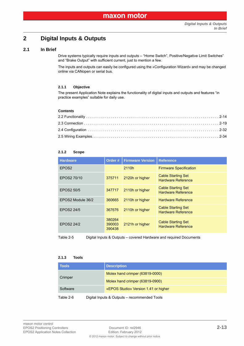
2 Digital Inputs & Outputs
2.1 In BriefDrive systems typically require inputs and outputs – “Home Switch”, Positive/Negative Limit Switches” and “Brake Output” with sufficient current, just to mention a few.
The inputs and outputs can easily be configured using the «Configuration Wizard» and may be changed online via CANopen or serial bus.
2.1.1 Objective
The present Application Note explains the functionality of digital inputs and outputs and features “in practice examples” suitable for daily use.
Contents
2.2 Functionality . . . . . . . . . . . . . . . . . . . . . . . . . . . . . . . . . . . . . . . . . . . . . . . . . . . . . . . . . . . . . . . . . 2-14
2.3 Connection . . . . . . . . . . . . . . . . . . . . . . . . . . . . . . . . . . . . . . . . . . . . . . . . . . . . . . . . . . . . . . . . . . 2-19
2.4 Configuration . . . . . . . . . . . . . . . . . . . . . . . . . . . . . . . . . . . . . . . . . . . . . . . . . . . . . . . . . . . . . . . . 2-32
2.5 Wiring Examples. . . . . . . . . . . . . . . . . . . . . . . . . . . . . . . . . . . . . . . . . . . . . . . . . . . . . . . . . . . . . . 2-34
2.1.2 Scope
Table 2-5 Digital Inputs & Outputs – covered Hardware and required Documents
2.1.3 Tools
Table 2-6 Digital Inputs & Outputs – recommended Tools
Hardware Order # Firmware Version Reference
EPOS2 2110h Firmware Specification
EPOS2 70/10 375711 2120h or higherCable Starting SetHardware Reference
EPOS2 50/5 347717 2110h or higherCable Starting SetHardware Reference
EPOS2 Module 36/2 360665 2110h or higher Hardware Reference
EPOS2 24/5 367676 2110h or higherCable Starting SetHardware Reference
EPOS2 24/2380264390003390438
2121h or higherCable Starting SetHardware Reference
Tools Description
CrimperMolex hand crimper (63819-0000)
Molex hand crimper (63819-0900)
Software «EPOS Studio» Version 1.41 or higher
Digital Inputs & OutputsFunctionality
© 2012 maxon motor. Subject to change without prior notice.
maxon motor control2-14 Document ID: rel2946 EPOS2 Positioning Controllers
Edition: February 2012 EPOS2 Application Notes Collection
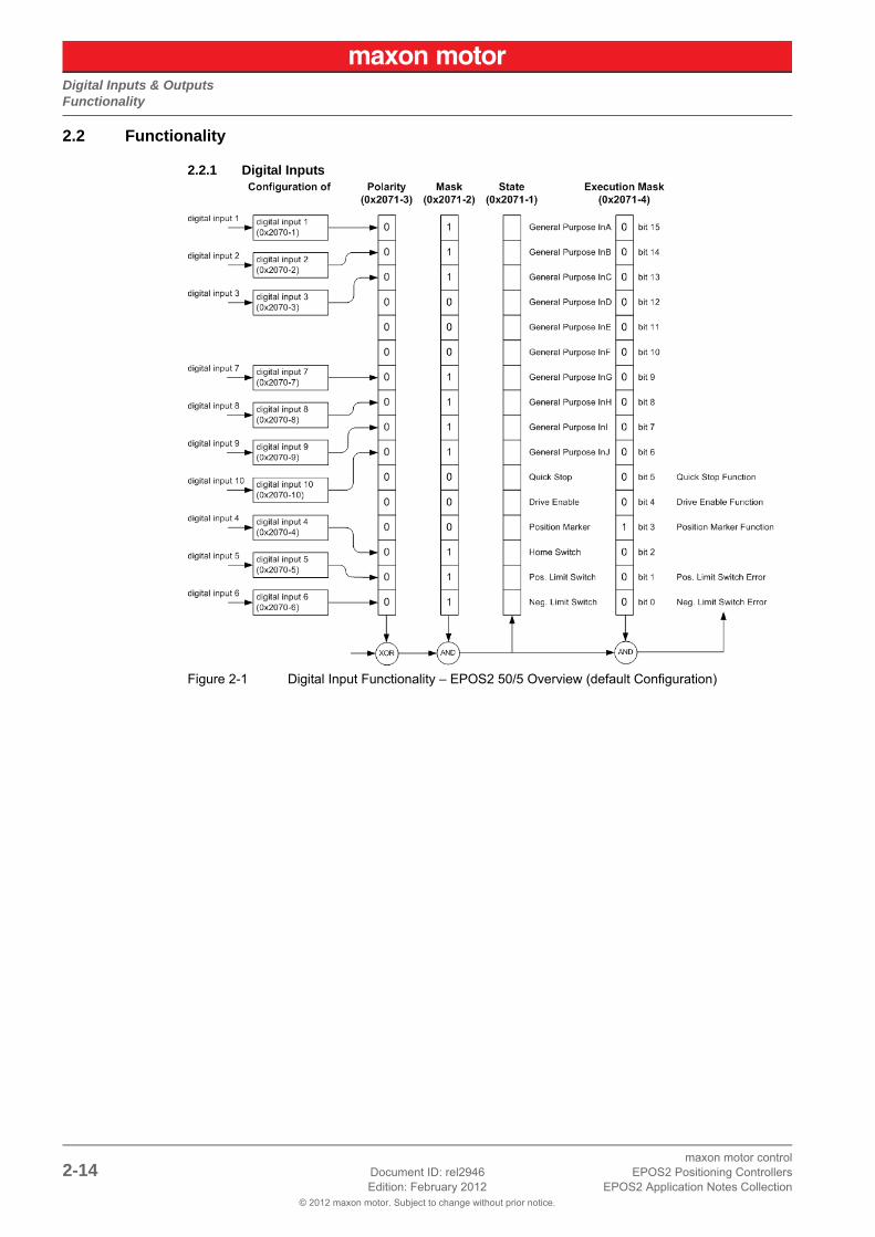
2.2 Functionality
2.2.1 Digital Inputs
Figure 2-1 Digital Input Functionality – EPOS2 50/5 Overview (default Configuration)

Digital Inputs & OutputsFunctionality
© 2012 maxon motor. Subject to change without prior notice.
maxon motor controlEPOS2 Positioning Controllers Document ID: rel2946 2-15EPOS2 Application Notes Collection Edition: February 2012
Configuration Parameter
Table 2-7 Digital Input – Configuration Parameter
Input Parameter
Table 2-8 Digital Input – Input Parameter
Name IndexSub-index
Description
Configuration of Digital Input 1 (Table 2-9)
0x2070 0x01 Defines functionality assigned to DigIN1.
Configuration of Digital Input 2 (Table 2-9)
0x2070 0x02 Defines functionality assigned to DigIN2.
Configuration of Digital Input 3 (Table 2-9)
0x2070 0x03 Defines functionality assigned to DigIN3.
Configuration of Digital Input 4 (Table 2-9)
0x2070 0x04 Defines functionality assigned to DigIN4.
Configuration of Digital Input 5 (Table 2-9)
0x2070 0x05Defines functionality assigned to DigIN5.Not available with EPOS2 Module 36/2!
Configuration of Digital Input 6 (Table 2-9)
0x2070 0x06Defines functionality assigned to DigIN6.Not available with EPOS2 Module 36/2!
Configuration of Digital Input 7 (Table 2-9)
0x2070 0x07Defines functionality assigned to DigIN7.Not available with EPOS2 24/5 and EPOS2 24/2!
Configuration of Digital Input 8 (Table 2-9)
0x2070 0x08Defines functionality assigned to DigIN8.Not available with EPOS2 24/5 and EPOS2 24/2!
Configuration of Digital Input 9 (Table 2-9)
0x2070 0x09Defines functionality assigned to DigIN9.Not available with EPOS2 Module 36/2, EPOS2 24/5 and EPOS2 24/2!
Configuration of Digital Input 10 (Table 2-9)
0x2070 0x0ADefines functionality assigned to DigIN10.Only available with EPOS2 50/5!
Digital Input Functionalities Mask (Table 2-10)
0x2071 0x02Displayed state of Digital Input Functionalities may be filtered.
Digital Input Functionalities Polarity (Table 2-11)
0x2071 0x03 Polarity of Digital Input Functionalities.
Digital Input Functionalities Execution Mask (Table 2-10)
0x2071 0x04Execution of Digital Input Functionalities can be inhibited.
Name IndexSub-index
Description
Digital Input Functionalities State (Table 2-10)
0x2071 0x01 Display state of Digital Input Functionalities.

Digital Inputs & OutputsFunctionality
© 2012 maxon motor. Subject to change without prior notice.
maxon motor control2-16 Document ID: rel2946 EPOS2 Positioning Controllers
Edition: February 2012 EPOS2 Application Notes Collection
Input Configuration Values
Parameter “Configuration of Digital Input” defines bit position in “Digital Input Functionalities State”.
Table 2-9 Digital Input – Input Configuration Values
Parameter Description
Table 2-10 Digital Input – Execution Mask Parameter
Polarity Values
Table 2-11 Digital Input – Polarity Values
Note• “Digital Input Functionalities State” will only be displayed, if “Digital Input Functionalities Mask” is set
to Enable.• “Digital Input Functionalities State” enables/disables the specific function.
Value Functionality Description
15 General Purpose A State can be read.
14 General Purpose B State can be read.
13 General Purpose C State can be read.
12 General Purpose D State can be read.
11 General Purpose E State can be read.
10 General Purpose F State can be read.
9 General Purpose G State can be read.
8 General Purpose H State can be read.
7 General Purpose I State can be read.
6 General Purpose J State can be read.
5 Quick Stop Set Quick Stop profile.
4 Device Enable Enables/disables device.
3 Position Marker Samples current position.
2 Home Switch Used in some homing modes.
1 Positive Limit Switch Generates limit error / used in some homing modes.
0 Negative Limit Switch Generates limit error / used in some homing modes.
Bit 15 Bit 14 Bit 13 Bit 12 Bit 11 Bit 10 Bit 9 Bit 8
General Purpose A
General Purpose B
General Purpose C
General Purpose D
General Purpose E
General Purpose F
General Purpose G
General Purpose H
Bit 7 Bit 6 Bit 5 Bit 4 Bit 3 Bit 2 Bit 1 Bit 0
General Purpose I
General Purpose J
Quick Stop
Device Enable
Position Marker
Home Switch
Pos. Limit Switch
Neg. Limit Switch
Bit 0 1
associated pin high active low active
Digital Inputs & OutputsFunctionality
© 2012 maxon motor. Subject to change without prior notice.
maxon motor controlEPOS2 Positioning Controllers Document ID: rel2946 2-17EPOS2 Application Notes Collection Edition: February 2012
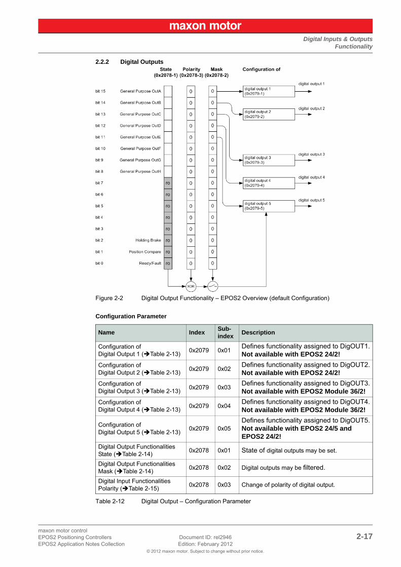
2.2.2 Digital Outputs
Figure 2-2 Digital Output Functionality – EPOS2 Overview (default Configuration)
Configuration Parameter
Table 2-12 Digital Output – Configuration Parameter
Name IndexSub-index
Description
Configuration of Digital Output 1 (Table 2-13)
0x2079 0x01Defines functionality assigned to DigOUT1.Not available with EPOS2 24/2!
Configuration of Digital Output 2 (Table 2-13)
0x2079 0x02Defines functionality assigned to DigOUT2.Not available with EPOS2 24/2!
Configuration of Digital Output 3 (Table 2-13)
0x2079 0x03Defines functionality assigned to DigOUT3.Not available with EPOS2 Module 36/2!
Configuration of Digital Output 4 (Table 2-13)
0x2079 0x04Defines functionality assigned to DigOUT4.Not available with EPOS2 Module 36/2!
Configuration of Digital Output 5 (Table 2-13)
0x2079 0x05Defines functionality assigned to DigOUT5.Not available with EPOS2 24/5 and EPOS2 24/2!
Digital Output Functionalities State (Table 2-14)
0x2078 0x01 State of digital outputs may be set.
Digital Output Functionalities Mask (Table 2-14)
0x2078 0x02 Digital outputs may be filtered.
Digital Input Functionalities Polarity (Table 2-15)
0x2078 0x03 Change of polarity of digital output.

Digital Inputs & OutputsFunctionality
© 2012 maxon motor. Subject to change without prior notice.
maxon motor control2-18 Document ID: rel2946 EPOS2 Positioning Controllers
Edition: February 2012 EPOS2 Application Notes Collection
Output Configuration Values
Parameter “Configuration of Digital Output” defines bit position in “Digital Output Functionalities State”.
Table 2-13 Digital Output – Output Configuration Values
Parameter Description
Table 2-14 Digital Output – Execution Mask Parameter
Polarity Values
Table 2-15 Digital Output – Polarity Values
NoteA change in “Digital Output Functionalities State” is only of effect, if “Digital Output Functionalities Mask” is set to Enable.
Value Functionality Description
15 General Purpose A State can be read.
14 General Purpose B State can be read.
13 General Purpose C State can be read.
12 General Purpose D State can be read.
11 General Purpose E State can be read.
10…8 not used –
7…3 reserved –
2 Holding BrakeActive output = activated brakeInactive output = deactivated brake
1 Position compare Trigger output of Position Compare.
0 Ready / Fault Active on Device Ready / Inactive on Fault
Bit 15 Bit 14 Bit 13 Bit 12 Bit 11 Bit 10…3 Bit 2 Bit 2 Bit 0
General Purpose A
General Purpose B
General Purpose C
General Purpose D
General Purpose E
not used / reserved
Holding Brake
Position Compare
Ready / Fault
Bit 0 1
associated pinnot inverted1 high0 low
inverted0 high1 low

Digital Inputs & OutputsConnection
© 2012 maxon motor. Subject to change without prior notice.
maxon motor controlEPOS2 Positioning Controllers Document ID: rel2946 2-19EPOS2 Application Notes Collection Edition: February 2012
2.3 Connection
2.3.1 EPOS2 70/10
EPOS Signal Cable 1 (275932) – Connector J5
Figure 2-3 EPOS Signal Cable 1
Table 2-16 EPOS Signal Cable 1 – Technical Data
Head A Head B
Technical Data
Cable cross-section 16 x 0.14 mm2
Length 3 m
Head AMolex Micro-Fit 3.0 16 poles (430-25-1600)Molex Micro-Fit 3.0 female crimp terminals (43030-xxxx)
Head B Cable end sleeves 0.14 mm2

Digital Inputs & OutputsConnection
© 2012 maxon motor. Subject to change without prior notice.
maxon motor control2-20 Document ID: rel2946 EPOS2 Positioning Controllers
Edition: February 2012 EPOS2 Application Notes Collection
Table 2-17 EPOS Signal Cable 1 – Pin Assignment EPOS2 70/10
WireHead A
PinHead B
PinTwisted
PairSignal Description
white 1 – IN_COM2 Common signal 2 for DigIN4…6
brown 2 – IN_COM1 Common signal 1 for DigIN1…3
green 3 – DigIN6Digital input 6 “Negative Limit Switch”
yellow 4 – DigIN5Digital input 5 “Positive Limit Switch”
grey 5 – DigIN4 Digital input 4 “Home Switch”
pink 6 – DigIN3 Digital input 3 “General Purpose”
blue 7 – DigIN2 Digital input 2 “General Purpose”
red 8 – DigIN1 Digital input 1 “General Purpose”
black 9 – +V Opto INExternal supply input voltage for Digital Outputs (+12…24 VDC)
violet 10 – DigOUT4 Digital output 4 “Brake”
grey/pink
11 – DigOUT3Digital output 3 “General Purpose”
red/blue 12 – DigOUT2Digital output 2 “General Purpose”
white/green
13 – DigOUT1Digital output 1 “General Purpose”
brown/green
14 – DigOUT_GndDigital OUT ground reference to “+V Opto IN”
white/yellow
15 – DigIN11Digital input 11 “Power Stage Enable”
yellow/brown
16 – IN_COM3 Common signal 3 for DigIN11

Digital Inputs & OutputsConnection
© 2012 maxon motor. Subject to change without prior notice.
maxon motor controlEPOS2 Positioning Controllers Document ID: rel2946 2-21EPOS2 Application Notes Collection Edition: February 2012
EPOS Signal Cable 2 (300586) – Connector J5A
Figure 2-4 EPOS Signal Cable 2
Table 2-18 EPOS Signal Cable 2 – Technical Data
Head A Head B
Technical Data
Cable cross-section 6 x 2 x 0.14 mm2
Length 3.00 m
Head AMolex Micro-Fit 3.0 12 poles (430-25-1200)Molex Micro-Fit 3.0 female crimp terminals (43030-xxxx)
Head B Cable end sleeves 0.14 mm2

Digital Inputs & OutputsConnection
© 2012 maxon motor. Subject to change without prior notice.
maxon motor control2-22 Document ID: rel2946 EPOS2 Positioning Controllers
Edition: February 2012 EPOS2 Application Notes Collection
Table 2-19 EPOS2 Signal Cable 2 – Pin Assignment EPOS2 70/10
WireHead A
PinHead B
PinTwisted
PairSignal Description
white 11
+5VOUT Reference output voltage +5 V
brown 2 A_Gnd Analog signal ground
green 32
AnIN2- Negative analog signal input 2
yellow 4 AnIN2+ Positive analog signal input 2
grey 53
AnIN1- Negative analog signal input 1
pink 6 AnIN1+ Positive analog signal input 1
blue 74
D_GND Digital signal ground
red 8 D_GND Digital signal ground
black 9
5
DigIN8/Digital input 8 “High Speed Command” complement or cos- input
violet 10 DigIN8Digital input 8 “High Speed Command” or cos+ input
grey/pink
11
6
DigIN7/Digital input 7 “High Speed Command” complement or sin- input
red/blue 12 DigIN7Digital input 7 “High Speed Command” or sin+ input

Digital Inputs & OutputsConnection
© 2012 maxon motor. Subject to change without prior notice.
maxon motor controlEPOS2 Positioning Controllers Document ID: rel2946 2-23EPOS2 Application Notes Collection Edition: February 2012
EPOS2 Signal Cable 4 (378173) – Connector J5B
Figure 2-5 EPOS2 Signal Cable 4
Table 2-20 EPOS2 Signal Cable 4 – Technical Data
Table 2-21 EPOS2 Signal Cable 4 – Pin Assignment EPOS2 70/10
Head A Head B
Technical Data
Cable cross-section 3 x 2 x 0.14 mm2, twisted pair
Length 3.00 m
Head AMolex Micro-Fit 3.0 6 poles (430-25-0600)Molex Micro-Fit 3.0 female crimp terminals (43030-xxxx)
Head B Cable end sleeves 0.14 mm2
WireHead A
PinHead B
PinTwisted
PairSignal Description
white 1
1
DigIN9/Digital input 9 “High Speed Command” complement
red 2 DigIN9Digital input 9 “High Speed Command”
brown 3 2 DigOUT5/Digital output 5 “High Speed Output” complement
green 43
+VAUXAuxiliary output voltage+5 VDC / 150 mA
yellow 5 D_GND Digital signal ground
grey 6 2 DigOUT5Digital output 5 “High Speed Output”
Digital Inputs & OutputsConnection
© 2012 maxon motor. Subject to change without prior notice.
maxon motor control2-24 Document ID: rel2946 EPOS2 Positioning Controllers
Edition: February 2012 EPOS2 Application Notes Collection
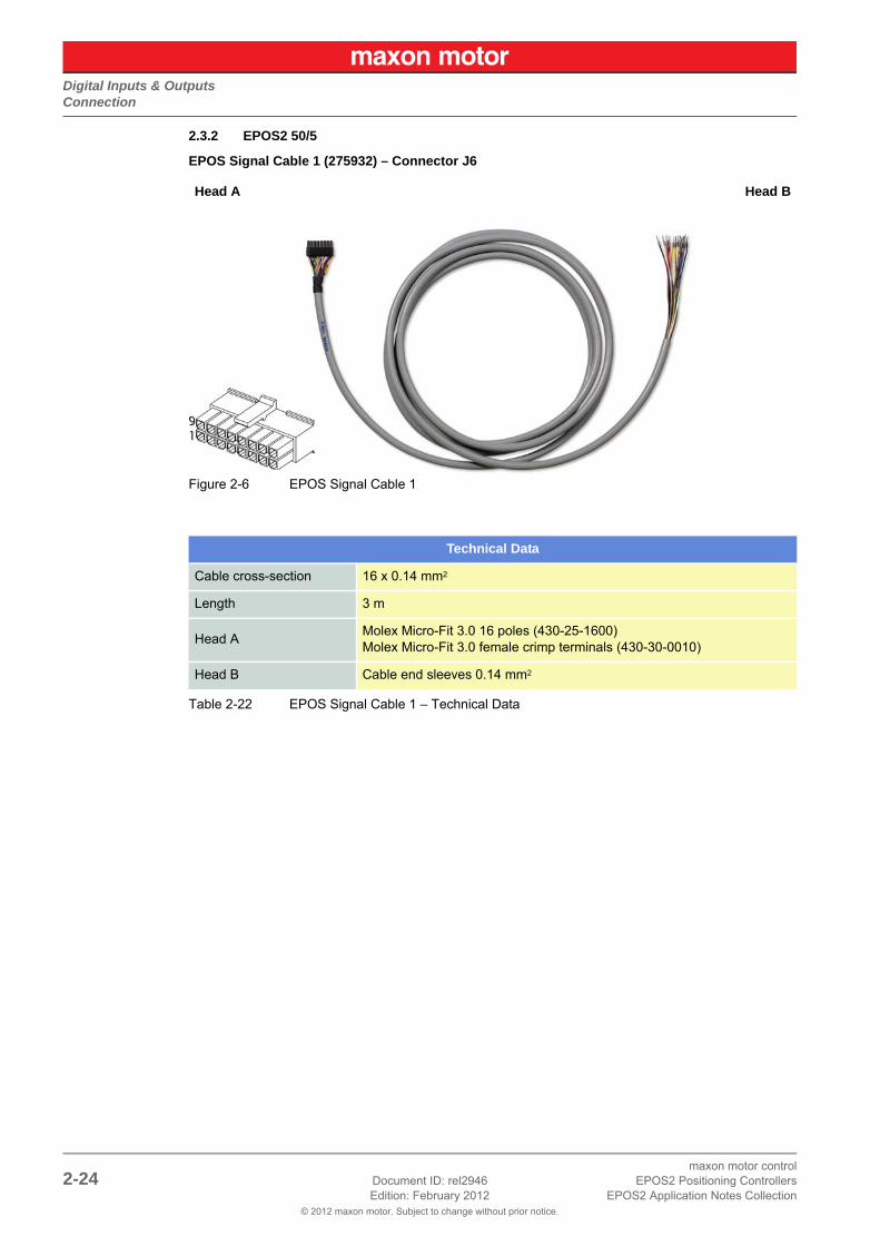
2.3.2 EPOS2 50/5
EPOS Signal Cable 1 (275932) – Connector J6
Figure 2-6 EPOS Signal Cable 1
Table 2-22 EPOS Signal Cable 1 – Technical Data
Head A Head B
Technical Data
Cable cross-section 16 x 0.14 mm2
Length 3 m
Head AMolex Micro-Fit 3.0 16 poles (430-25-1600)Molex Micro-Fit 3.0 female crimp terminals (430-30-0010)
Head B Cable end sleeves 0.14 mm2

Digital Inputs & OutputsConnection
© 2012 maxon motor. Subject to change without prior notice.
maxon motor controlEPOS2 Positioning Controllers Document ID: rel2946 2-25EPOS2 Application Notes Collection Edition: February 2012
Table 2-23 EPOS Signal Cable 1 – Pin Assignment EPOS2 50/5
WireHead A
PinHead B
PinTwisted
PairSignal Description
white 1 – IN_COM2 Common signal 2 for DigIN4…6
brown 2 – IN_COM1 Common signal 1 for DigIN1…3
green 3 – DigIN6Digital Input 6 “Negative Limit Switch”
yellow 4 – DigIN5Digital Input 5 “Positive Limit Switch”
grey 5 – DigIN4 Digital Input 4 “Home Switch”
pink 6 – DigIN3 Digital Input 3 “General Purpose”
blue 7 – DigIN2 Digital Input 2 “General Purpose”
red 8 – DigIN1 Digital Input 1 “General Purpose”
black 9 – +V Opto INExternal supply input voltage for Digital Outputs (+12…24 VDC)
violet 10 – DigOUT4Digital Output 4 “Brake / General Purpose”
grey/pink
11 – DigOUT3Digital Output 3 “Brake / General Purpose”
red/blue 12 – DigOUT2Digital Output 2 “General Purpose”
white/green
13 – DigOUT1Digital Output 1 “General Purpose”
brown/green
14 – DigOUT_GndDigital OUT ground reference to “+V Opto IN”
white/yellow
15 – DigIN11Digital Input 11 “Power Stage Enable”
yellow/brown
16 – IN_COM3 Common signal 3 for DigIN11

Digital Inputs & OutputsConnection
© 2012 maxon motor. Subject to change without prior notice.
maxon motor control2-26 Document ID: rel2946 EPOS2 Positioning Controllers
Edition: February 2012 EPOS2 Application Notes Collection
EPOS Signal Cable 2 (300586) – Connector J5
Figure 2-7 EPOS Signal Cable 2
Table 2-24 EPOS Signal Cable 2 – Technical Data
Head A Head B
Technical Data
Cable cross-section 6 x 2 x 0.14 mm2
Length 3.00 m
Head AMolex Micro-Fit 3.0 12 poles (430-25-1200)Molex Micro-Fit 3.0 female crimp terminals (430-30-0010)
Head B Cable end sleeves 0.14 mm2

Digital Inputs & OutputsConnection
© 2012 maxon motor. Subject to change without prior notice.
maxon motor controlEPOS2 Positioning Controllers Document ID: rel2946 2-27EPOS2 Application Notes Collection Edition: February 2012
Table 2-25 EPOS2 Signal Cable 3 – Pin Assignment EPOS2 50/5
WireHead A
PinHead B
PinTwisted
PairSignal Description
white 1
1
DigIN10/Digital Input 10 “High Speed Command” complement
brown 2 DigIN10Digital Input 10 “High Speed Command”
green 3
2
DigIN9/Digital Input 9 “High Speed Command” complement
yellow 4 DigIN9Digital Input 9 “High Speed Command”
grey 5
3
DigIN7/Digital Input 7 “High Speed Command” complement
pink 6 DigIN7Digital Input 7 “High Speed Command”
blue 7
4
DigIN8/Digital Input 8 “High Speed Command” complement
red 8 DigIN8Digital Input 8 “High Speed Command”
black 95
+VAUXAuxiliary output voltage +5 VDC / 150 mA
violet 10 D_GND Digital signal ground
grey/pink
11
6
DigOUT5/Digital Output 5 “High Speed Command” complement
red/blue 12 DigOUT5Digital Output 5 “High Speed Command”

Digital Inputs & OutputsConnection
© 2012 maxon motor. Subject to change without prior notice.
maxon motor control2-28 Document ID: rel2946 EPOS2 Positioning Controllers
Edition: February 2012 EPOS2 Application Notes Collection
2.3.3 EPOS2 Module 36/2
Connector Array
Figure 2-8 EPOS2 Module 36/2 – PCB with Connector Array
Table 2-26 EPOS2 Module 36/2 – PCB Connectors
Table 2-27 EPOS2 Module 36/2 – Pin Assignment
PCB Connectors
PCB On-board card edge connector
Suitable plugs
PCI Express (PCIe), 2 x 32 pins (vertical or horizontal), pitch 1 mmVertical:Tyco (2-1775801-1) or FCI (10018783-11111TLF) Horizontal:Tyco (1761465-2) or Meritec (983172-064-2MMF)
Suitable retainer FCI PCI Express Retainer, blue (10042618-002LF)
Pin Signal Description
A6 Power_GND Ground of supply voltage
A10+Vaux Auxiliary voltage output +5 VDC
+VDDin Auxiliary supply voltage input +5 VDC (optional)
A21 GND Ground of digital output
A22 DigOUT5 Digital Output 5
B12 GND Ground of digital input
B13 DigIN1 Digital Input 1
B14 DigIN2 Digital Input 2
B15 DigIN3 Digital Input 3
B16 DigIN4 Digital Input 4
B17 GND Ground of digital input
B18 DigIN7 Digital Input 7 “High Speed Command”
B19 DigIN7\ Digital Input 7 “High Speed Command” complement
B20 DigIN8 Digital Input 8 “High Speed Command”
B21 DigIN8\ Digital Input 8 “High Speed Command” complement
B22 DigOUT1 Digital Output 1
B23 DigOUT2 Digital Output 2

Digital Inputs & OutputsConnection
© 2012 maxon motor. Subject to change without prior notice.
maxon motor controlEPOS2 Positioning Controllers Document ID: rel2946 2-29EPOS2 Application Notes Collection Edition: February 2012
2.3.4 EPOS2 24/5
EPOS Signal Cable 1 (275932) – Connector J6
Figure 2-9 EPOS Signal Cable 1
Table 2-28 EPOS Signal Cable 1 – Technical Data
Head A Head B
Technical Data
Cable cross-section 16 x 0.14 mm2
Length 3 m
Head AMolex Micro-Fit 3.0 16 poles (430-25-1600)Molex Micro-Fit 3.0 female crimp terminals (430-30-0010)
Head B Cable end sleeves 0.14 mm2

Digital Inputs & OutputsConnection
© 2012 maxon motor. Subject to change without prior notice.
maxon motor control2-30 Document ID: rel2946 EPOS2 Positioning Controllers
Edition: February 2012 EPOS2 Application Notes Collection
Table 2-29 EPOS Signal Cable 1 – Pin Assignment EPOS2 24/5
WireHead A
PinHead B
PinTwisted
PairSignal Description
white 1 – D_Gnd Digital signal ground
brown 2 – D_Gnd Digital signal ground
green 3 – DigIN6Digital Input 6 “Negative Limit Switch”
yellow 4 – DigIN5Digital Input 5 “Positive Limit Switch”
grey 5 – DigIN4 Digital Input 4 “Home switch”
pink 6 – DigIN3 Digital Input 3 “General Purpose”
blue 7 – DigIN2 Digital Input 2 “General Purpose”
red 8 – DigIN1 Digital Input 1 “General Purpose”
black
9 *1)
–
+VoutAuxiliary supply voltage output (+11…+24 VDC)
9 *2) +VCLogic supply voltage output (+11…+24 VDC)
violet 10 – DigOUT4 Digital Output 4 “Brake”
grey/pink
11 – DigOUT3Digital Output 3 “General Purpose”
red/blue 12 – DigOUT2Digital Output 2 “General Purpose”
white/green
13 – DigOUT1Digital Output 1 “General Purpose”
brown/green
14 – A_Gnd Analog signal ground
white/yellow
15 – AnIN2 Analog Input 2
yellow/brown
16 – AnIN1 Analog Input 1
Remarks:*1) jumper JP4 is set (initial setting)*2) if jumper JP4 is open, a separate logic supply voltage may be applied

Digital Inputs & OutputsConnection
© 2012 maxon motor. Subject to change without prior notice.
maxon motor controlEPOS2 Positioning Controllers Document ID: rel2946 2-31EPOS2 Application Notes Collection Edition: February 2012
2.3.5 EPOS2 24/2
Connector J1
Figure 2-10 Connector J1
Table 2-30 Connector J1 – Pin Assignment EPOS2 24/2
WireHead A
PinHead B
PinTwisted
PairSignal Description
– 1 – DigIN1 Digital Input 1 “General Purpose”
– 2 – DigIN2 Digital Input 2 “General Purpose”
– 3 – DigIN3 Digital Input 3 “General Purpose”
– 4 – DigIN4 Digital Input 4 “Home Switch”
– 5 – DigIN5Digital Input 5 “Positive Limit Switch”
– 6 – DigIN6Digital Input 6 “Negative Limit Switch”
– 7 – D_Gnd Digital signal ground
– 8 – +VOUTAuxiliary supply voltage Output (+5 VDC / 10 mA)
– 9 – DigOUT3Digital Output 3 “General Purpose”
– 10 – DigOUT4Digital Output 4 “General Purpose”
– 11 – D_Gnd Digital signal ground
– 12 – Power_Gnd Power ground
– 13 – +VCCPower supply voltage (+9…24 VDC)

Digital Inputs & OutputsConfiguration
© 2012 maxon motor. Subject to change without prior notice.
maxon motor control2-32 Document ID: rel2946 EPOS2 Positioning Controllers
Edition: February 2012 EPOS2 Application Notes Collection
2.4 ConfigurationConfiguration is handled by a dynamic wizard assisting you in selecting desired functions and assigning them to inputs and outputs of you choice.
NoteThe following explanations show you how to initiate the Configuration Wizard. Its further coarse will then depend on the functions and options you will actually chose. The stated figures are thereby meant as examples.
2.4.1 Step A: Open I/O Configuration Wizard
1) Complete standard system configuration (Startup Wizard) in «EPOS Studio».
2) Doubleclick ¤I/O Configuration Wizard¤ to commence configuration.
Figure 2-11 Open I/O Configuration Wizard
3) A screen will appear showing the number of I/Os available for configuration.
4) Click ¤Next¤ to continue.
Figure 2-12 Configuration Wizard – Introduction
2.4.2 Step B: Configure Digital Inputs
1) Select predefined functions you wish to use by ticking respective check boxes. An available digi-tal input will automatically be assigned to your selection.
2) If you wish to assign a particular digital input to a given function, select desired input from the ¤Dropdown menu¤ in column “Input”.
3) Click ¤Next¤ to continue.
Figure 2-13 Configuration Wizard – Configure Digital Inputs

Digital Inputs & OutputsConfiguration
© 2012 maxon motor. Subject to change without prior notice.
maxon motor controlEPOS2 Positioning Controllers Document ID: rel2946 2-33EPOS2 Application Notes Collection Edition: February 2012
4) Define mask, type of switch (NPN or PNP) and switch output state.
5) Set limit switch error.
6) Click ¤Next¤ to continue.
7) Repeat for every earlier selected digital input.
Figure 2-14 Configuration Wizard – Configure Digital Input Functionality
2.4.3 Step C: Configure Digital Outputs
1) Select predefined functions you wish to use by ticking respective check boxes. An available digi-tal output will automatically be assigned to your selection.
2) If you wish to assign a particular digital output to a given function, select desired input from the ¤Dropdown menu¤ in column “Output”.
3) Click ¤Next¤ to continue.
Figure 2-15 Configuration Wizard – Configure Digital Outputs
2.4.4 Step D: Save Configuration
Figure 2-16 Safe Configuration
NoteYou may check the status and alter the configuration at any time using the «I/O Monitor».

Digital Inputs & OutputsWiring Examples
© 2012 maxon motor. Subject to change without prior notice.
maxon motor control2-34 Document ID: rel2946 EPOS2 Positioning Controllers
Edition: February 2012 EPOS2 Application Notes Collection
2.5 Wiring Examples
2.5.1 EPOS2 70/10
2.5.1.1 Proximity Switches
Figure 2-17 EPOS2 70/10 – DigIN4…6 / Proximity Switches
Best Practice• Preferably, use 3-wire PNP proximity switches.• Using 3-wire NPN proximity switches requires an additional pull-up resistor.
Rext (12 V) = 560 Ω (300 mW)Rext (24 V) = 3 kΩ (200 mW)
• By principle, using 2-wire proximity switches is possible.

Digital Inputs & OutputsWiring Examples
© 2012 maxon motor. Subject to change without prior notice.
maxon motor controlEPOS2 Positioning Controllers Document ID: rel2946 2-35EPOS2 Application Notes Collection Edition: February 2012
2.5.1.2 Permanent Magnet Brake
EPOS2 70/10 output 4 permits direct activation of loads with very high current demand (such as motor brakes and warning lights, etc.).
Figure 2-18 EPOS2 70/10 – DigOUT4 / permanent Magnet Brake
2.5.2 EPOS2 50/5
2.5.2.1 Proximity Switches
Figure 2-19 EPOS2 50/5 – DigIN4…6 / PNP/NPN Proximity Switches
Best Practice• We recommend the use of 3-wire PNP proximity switches.• The use of 3-wire NPN proximity switches requires an additional external pull-up resistor:
– Rext (12 V) = 560 Ω (300 mW)– Rext (24 V) = 3 kΩ (200 mW)
• The use of 2-wire proximity switches is possible.

Digital Inputs & OutputsWiring Examples
© 2012 maxon motor. Subject to change without prior notice.
maxon motor control2-36 Document ID: rel2946 EPOS2 Positioning Controllers
Edition: February 2012 EPOS2 Application Notes Collection
2.5.2.2 Permanent Magnet Brake
EPOS2 50/5 output 4 permits direct activation of loads with very high current demand (such as motor brakes and warning lights, etc.).
Figure 2-20 EPOS2 50/5 – DigOUT4 / permanent Magnet Brake
2.5.3 EPOS2 Module 36/2
2.5.3.1 Digital Inputs
Figure 2-21 EPOS2 Module 36/2 – DigIN4 / PNP Proximity Switch (applies also for DigIN2/3)
Figure 2-22 EPOS2 Module 36/2 – DigIN4 / Photoelectric Sensor (applies also for DigIN2/3)
PNP 3-Wire Model
Photoelectric Sensor
Note:Logic level threshold VIN assumed 5 V.Rext
RIN VS VIN )–(⋅VIN
---------------------------------------=

Digital Inputs & OutputsWiring Examples
© 2012 maxon motor. Subject to change without prior notice.
maxon motor controlEPOS2 Positioning Controllers Document ID: rel2946 2-37EPOS2 Application Notes Collection Edition: February 2012
2.5.3.2 Digital Outputs
Figure 2-23 EPOS2 Module 36/2 – DigOUT1 “sink” (applies also for DigIN2)
Figure 2-24 EPOS2 Module 36/2 – DigOUT1 “source” (applies also for DigIN2)
Digital Output 1 “sink”
Max. input voltageMax. load currentMax. voltage drop
+36 VDC50 mA<1.0 V @ 50 mA
Digital Output 1 “source”
Output voltageMax. load current
Uout ≈ 5 V - 0.75 V - (Iload x 2200 Ω)Iload ≤ 2 mA

Digital Inputs & OutputsWiring Examples
© 2012 maxon motor. Subject to change without prior notice.
maxon motor control2-38 Document ID: rel2946 EPOS2 Positioning Controllers
Edition: February 2012 EPOS2 Application Notes Collection
2.5.4 EPOS2 24/5
2.5.4.1 Proximity Switches
Figure 2-25 EPOS2 24/5 – DigIN4 / PNP Proximity Switch (applies also for DigIN5/6)
Figure 2-26 EPOS2 24/5 – DigIN4 / NPN Proximity Switch (applies also for DigIN5/6)
PNP 3-Wire Model
NPN 3-Wire Model NPN 2-Wire Model
Rext (12 V) = 510 Ω (300 mW)Rext (24 V) = 4.3 kΩ (150 mW)RIN = 4 kΩ

Digital Inputs & OutputsWiring Examples
© 2012 maxon motor. Subject to change without prior notice.
maxon motor controlEPOS2 Positioning Controllers Document ID: rel2946 2-39EPOS2 Application Notes Collection Edition: February 2012
2.5.4.2 Digital Outputs
Figure 2-27 EPOS2 24/5 – DigOUT1 “sink”
Figure 2-28 EPOS2 24/5 – DigOUT1 “source”
Digital Output “sink”
Max. input voltageMax. load currentMax. voltage drop
+30 VDC100 mA0.5 V @ 100 mA
Digital Output “source”
Output voltageMax. load current
Uout ≈ 5 V - 0.75 V - (Iload x 2200 Ω)Iload ≤ 2 mA

Digital Inputs & OutputsWiring Examples
© 2012 maxon motor. Subject to change without prior notice.
maxon motor control2-40 Document ID: rel2946 EPOS2 Positioning Controllers
Edition: February 2012 EPOS2 Application Notes Collection
2.5.5 EPOS2 24/2
2.5.5.1 Proximity Switches
Figure 2-29 EPOS2 24/2 – DigIN4 / PNP Proximity Switch (applies also for DigIN5/6)
2.5.5.2 Photoelectric Sensor
Figure 2-30 EPOS2 24/2 – DigIN4 / Photoelectric Sensor (analogously valid also for DigIN5/6)
PNP 3-Wire ModelRIN = 11 kΩ
3-Wire ModelRext = (12 V) = 20 kΩ (300 mW)Rext = (24 V) = 51 kΩ (150 mW)RIN = 11 kΩ

Analog Inputs & OutputsIn Brief
© 2012 maxon motor. Subject to change without prior notice.
maxon motor controlEPOS2 Positioning Controllers Document ID: rel2946 3-41EPOS2 Application Notes Collection Edition: February 2012
3 Analog Inputs & Outputs
3.1 In BriefDrive systems typically require inputs and outputs.
The analog inputs may be used for general purpose process values (such as temperature, pressure, torque from an external sensor, etc.). Also featured are predefined functions for analog inputs (such as respective setpoints for Current Mode, Velocity Mode and Position Mode).
EPOS2 50/5 additionally supports an analog output for general purposes.
The inputs and outputs can easily be configured using the «Configuration Wizard» and may be changed online via CANopen or serial bus.
3.1.1 Objective
The present Application Note explains the functionality of analog inputs and outputs and features “in practice examples” suitable for daily use.
Contents
3.2 Functionality . . . . . . . . . . . . . . . . . . . . . . . . . . . . . . . . . . . . . . . . . . . . . . . . . . . . . . . . . . . . . . . . . 3-42
3.3 Connection . . . . . . . . . . . . . . . . . . . . . . . . . . . . . . . . . . . . . . . . . . . . . . . . . . . . . . . . . . . . . . . . . . 3-45
3.4 Configuration . . . . . . . . . . . . . . . . . . . . . . . . . . . . . . . . . . . . . . . . . . . . . . . . . . . . . . . . . . . . . . . . 3-52
3.1.2 Scope
Table 3-31 Analog Inputs & Outputs – covered Hardware and required Documents
3.1.3 Tools
Table 3-32 Analog Inputs & Outputs – recommended Tools
Hardware Order # Firmware Version Reference
EPOS2 2110h Firmware Specification
EPOS2 70/10 375711 2120h or higherCable Starting SetHardware Reference
EPOS2 50/5 347717 2110h or higherCable Starting SetHardware Reference
EPOS2 Module 36/2 360665 2110h or higher Hardware Reference
EPOS2 24/5 367676 2110h or higherCable Starting SetHardware Reference
EPOS2 24/2380264390003390438
2121h or higherCable Starting SetHardware Reference
Tools Description
CrimperMolex hand crimper (63819-0000)
Molex hand crimper (63819-0900)
Software «EPOS Studio» Version 1.41 or higher
Analog Inputs & OutputsFunctionality
© 2012 maxon motor. Subject to change without prior notice.
maxon motor control3-42 Document ID: rel2946 EPOS2 Positioning Controllers
Edition: February 2012 EPOS2 Application Notes Collection
3.2 Functionality
3.2.1 Analog Inputs
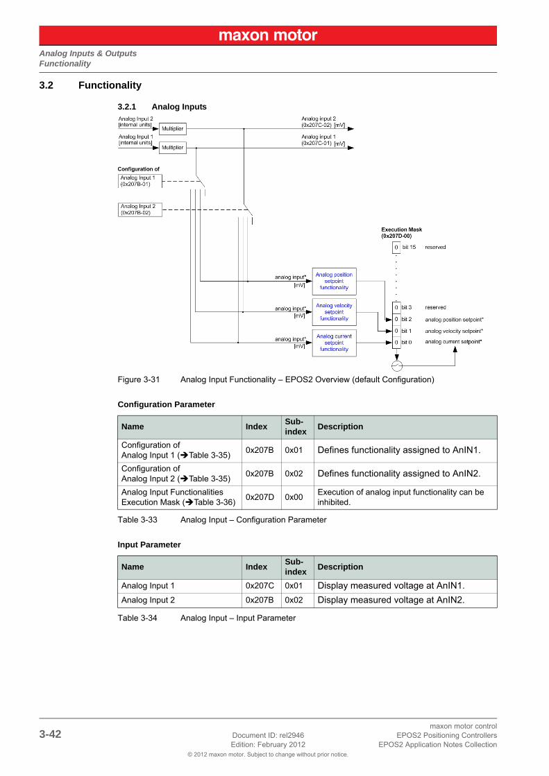
Figure 3-31 Analog Input Functionality – EPOS2 Overview (default Configuration)
Configuration Parameter
Table 3-33 Analog Input – Configuration Parameter
Input Parameter
Table 3-34 Analog Input – Input Parameter
Name IndexSub-index
Description
Configuration of Analog Input 1 (Table 3-35)
0x207B 0x01 Defines functionality assigned to AnIN1.
Configuration of Analog Input 2 (Table 3-35)
0x207B 0x02 Defines functionality assigned to AnIN2.
Analog Input Functionalities Execution Mask (Table 3-36)
0x207D 0x00Execution of analog input functionality can be inhibited.
Name IndexSub-index
Description
Analog Input 1 0x207C 0x01 Display measured voltage at AnIN1.
Analog Input 2 0x207B 0x02 Display measured voltage at AnIN2.

Analog Inputs & OutputsFunctionality
© 2012 maxon motor. Subject to change without prior notice.
maxon motor controlEPOS2 Positioning Controllers Document ID: rel2946 3-43EPOS2 Application Notes Collection Edition: February 2012
Input Configuration Values
Parameter “Configuration of Analog Input” defines bit position in “Analog Input Functionalities State”.
Table 3-35 Analog Input – Input Configuration Values
Parameter Description
Table 3-36 Analog Input – Execution Mask Parameter
NoteWith the execution mask, execution of analog input functionality can be inhibited.
Value Functionality Description
15 General Purpose A State can be read.
14 General Purpose B State can be read.
13 General Purpose C State can be read.
12 General Purpose D State can be read.
11 General Purpose E State can be read.
10 General Purpose F State can be read.
9 General Purpose G State can be read.
8 General Purpose H State can be read.
7…3 reserved –
2 Position SetpointAnalog input is used to command control function in Position Mode.
1 Velocity SetpointAnalog input is used to command control function in Velocity Mode.
0 Current SetpointAnalog input is used to command control function in Current Mode.
Bit 15 Bit 14 Bit 13 Bit 12 Bit 11 Bit 10 Bit 9 Bit 8
reserved reserved reserved reserved reserved reserved reserved reserved
Bit 7 Bit 6 Bit 5 Bit 4 Bit 3 Bit 2 Bit 1 Bit 0
reserved reserved reserved reserved reservedPosition Setpoint
Velocity Setpoint
Current Setpoint

Analog Inputs & OutputsFunctionality
© 2012 maxon motor. Subject to change without prior notice.
maxon motor control3-44 Document ID: rel2946 EPOS2 Positioning Controllers
Edition: February 2012 EPOS2 Application Notes Collection
3.2.2 Analog Output (EPOS2 50/5 only)
Figure 3-32 Analog Output Functionality – EPOS2 Overview (default Configuration)
Output Parameter
Table 3-37 Analog Output – Output Parameter
NoteThis object is used to set the voltage level [mV] of the Analog Output 1. Immediately after write to this object, the value is transferred to the Analog Output 1.
Name IndexSub-index
Description
Analog Output 1 0x207E 0x00 Defines voltage level set at AnOUT1.

Analog Inputs & OutputsConnection
© 2012 maxon motor. Subject to change without prior notice.
maxon motor controlEPOS2 Positioning Controllers Document ID: rel2946 3-45EPOS2 Application Notes Collection Edition: February 2012
3.3 Connection
3.3.1 EPOS2 70/10
EPOS Signal Cable 2 (300586) – Connector J5A
Figure 3-33 EPOS Signal Cable 2
Table 3-38 EPOS Signal Cable 2 – Technical Data
Head A Head B
Technical Data
Cable cross-section 6 x 2 x 0.14 mm2
Length 3.00 m
Head AMolex Micro-Fit 3.0 12 poles (430-25-1200)Molex Micro-Fit 3.0 female crimp terminals (43030-xxxx)
Head B Cable end sleeves 0.14 mm2

Analog Inputs & OutputsConnection
© 2012 maxon motor. Subject to change without prior notice.
maxon motor control3-46 Document ID: rel2946 EPOS2 Positioning Controllers
Edition: February 2012 EPOS2 Application Notes Collection
Table 3-39 EPOS2 Signal Cable 2 – Pin Assignment EPOS2 70/10
WireHead A
PinHead B
PinTwisted
PairSignal Description
white 11
+5VOUT Reference output voltage +5 V
brown 2 A_Gnd Analog signal ground
green 32
AnIN2- Negative analog signal input 2
yellow 4 AnIN2+ Positive analog signal input 2
grey 53
AnIN1- Negative analog signal input 1
pink 6 AnIN1+ Positive analog signal input 1
blue 74
D_GND Digital signal ground
red 8 D_GND Digital signal ground
black 9
5
DigIN8/Digital input 8 “High Speed Command” complement or cos- input
violet 10 DigIN8Digital input 8 “High Speed Command” or cos+ input
grey/pink
11
6
DigIN7/Digital input 7 “High Speed Command” complement or sin- input
red/blue 12 DigIN7Digital input 7 “High Speed Command” or sin+ input

Analog Inputs & OutputsConnection
© 2012 maxon motor. Subject to change without prior notice.
maxon motor controlEPOS2 Positioning Controllers Document ID: rel2946 3-47EPOS2 Application Notes Collection Edition: February 2012
3.3.2 EPOS2 50/5
EPOS2 Signal Cable 3 (350390) – Connector J7
Figure 3-34 EPOS2 Signal Cable 3
Table 3-40 EPOS2 Signal Cable 3 – Technical Data
Table 3-41 EPOS2 Signal Cable 3 – Pin Assignment EPOS2 50/5
Head A Head B
Technical Data
Cable cross-section 4 x 2 x 0.14 mm2
Length 3.00 m
Head AMolex Micro-Fit 3.0 8 poles (430-25-0800)Molex Micro-Fit 3.0 female crimp terminals (430-30-0010)
Head B Cable end sleeves 0.14 mm2
WireHead A
PinHead B
PinTwisted
PairSignal Description
white 1 1 AnOUT1Analog signal output 1”General Purpose”
red 2 4 not connected –
brown 3 1 A_Gnd Analog signal ground
green 4 2 AnIN2-Negative analog signal input 2 “General Purpose”
yellow 5 2 AnIN2+Positive analog signal input 2 “General Purpose”
grey 6 3 AnIN1-Negative analog signal input 1 “General Purpose”
pink 7 3 AnIN1+Positive analog signal input 1 “General Purpose”
blue 8 4 A_Gnd Analog signal ground

Analog Inputs & OutputsConnection
© 2012 maxon motor. Subject to change without prior notice.
maxon motor control3-48 Document ID: rel2946 EPOS2 Positioning Controllers
Edition: February 2012 EPOS2 Application Notes Collection
3.3.3 EPOS2 Module 36/2
Connector Array
Figure 3-35 EPOS2 Module 36/2 – PCB with Connector Array
Table 3-42 EPOS2 Module 36/2 – PCB Connectors
Table 3-43 EPOS2 Module 36/2 – Pin Assignment
PCB Connectors
PCB On-board card edge connector
Suitable plugs
PCI Express (PCIe), 2 x 32 pins (vertical or horizontal), pitch 1 mmVertical:Tyco (2-1775801-1) or FCI (10018783-11111TLF) Horizontal:Tyco (1761465-2) or Meritec (983172-064-2MMF)
Suitable retainer FCI PCI Express Retainer, blue (10042618-002LF)
Pin Signal Description
A18 GND Analog input ground
A19 AnIN1 Analog Input 1
A20 AnIN2 Analog Input 2
others separate document «EPOS2 Module 36/2 Hardware Reference»

Analog Inputs & OutputsConnection
© 2012 maxon motor. Subject to change without prior notice.
maxon motor controlEPOS2 Positioning Controllers Document ID: rel2946 3-49EPOS2 Application Notes Collection Edition: February 2012
3.3.4 EPOS2 24/5
EPOS Signal Cable 1 (275932) – Connector J5
Figure 3-36 EPOS Signal Cable 1
Table 3-44 EPOS Signal Cable 1 – Technical Data
Head A Head B
Technical Data
Cable cross-section 16 x 0.14 mm2
Length 3 m
Head AMolex Micro-Fit 3.0 16 poles (430-25-1600)Molex Micro-Fit 3.0 female crimp terminals (430-30-0010)
Head B Cable end sleeves 0.14 mm2

Analog Inputs & OutputsConnection
© 2012 maxon motor. Subject to change without prior notice.
maxon motor control3-50 Document ID: rel2946 EPOS2 Positioning Controllers
Edition: February 2012 EPOS2 Application Notes Collection
Table 3-45 EPOS Signal Cable 1 – Pin Assignment EPOS2 24/5
WireHead A
PinHead B
PinTwisted
PairSignal Description
white 1 – D_Gnd Digital signal ground
brown 2 – D_Gnd Digital signal ground
green 3 – DigIN6Digital Input 6“Negative Limit Switch”
yellow 4 – DigIN5Digital Input 5“Positive Limit Switch”
grey 5 – DigIN4 Digital Input 4 “Home switch”
pink 6 – DigIN3 Digital Input 3 “General Purpose”
blue 7 – DigIN2 Digital Input 2 “General Purpose”
red 8 – DigIN1 Digital Input 1 “General Purpose”
black
9 *1)
–
+VoutAuxiliary supply voltage output (+11…+24 VDC)
9 *2) +VCLogic supply voltage output (+11…+24 VDC)
violet 10 – DigOUT4 Digital Output 4 “Brake”
grey/pink
11 – DigOUT3Digital Output 3“General Purpose”
red/blue 12 – DigOUT2Digital Output 2“General Purpose”
white/green
13 – DigOUT1Digital Output 1“General Purpose”
brown/green
14 – A_Gnd Analog signal ground
white/yellow
15 – AnIN2 Analog Input 2
yellow/brown
16 – AnIN1 Analog Input 1
Remarks:*1) jumper JP4 is set (initial setting)*2) if jumper JP4 is open, a separate logic supply voltage may be applied

Analog Inputs & OutputsConnection
© 2012 maxon motor. Subject to change without prior notice.
maxon motor controlEPOS2 Positioning Controllers Document ID: rel2946 3-51EPOS2 Application Notes Collection Edition: February 2012
3.3.5 EPOS2 24/2
Connector J2
Table 3-46 Connector J2
Table 3-47 Connector J2 – Pin Assignment EPOS2 24/2
WireHead A
PinHead B
PinTwisted
PairSignal Description
– 1 1 CAN high CAN high bus line
– 2 4 CAN low CAN low bus line
– 3 1 RS232 RxD RS232 receive
– 4 2 RS232 TxD RS232 transmit
– 5 2 GND Ground
– 6 3 AnIN1 Analog Input 1
– 7 3 AnIN2 Analog Input 2
– 8 4 A_Gnd Analog signal ground

Analog Inputs & OutputsConfiguration
© 2012 maxon motor. Subject to change without prior notice.
maxon motor control3-52 Document ID: rel2946 EPOS2 Positioning Controllers
Edition: February 2012 EPOS2 Application Notes Collection
3.4 ConfigurationConfiguration is handled by a dynamic wizard assisting you in selecting desired functions and assigning them to inputs and outputs of you choice.
NoteThe following explanations show you how to initiate the Configuration Wizard. Its further coarse will then depend on the functions and options you will actually chose. The stated figures are thereby meant as examples.
3.4.1 Step A: Open I/O Configuration Wizard
1) Complete standard system configuration (Startup Wizard) in «EPOS Studio».
2) Doubleclick ¤I/O Configuration Wizard¤ to commence configuration.
Figure 3-37 Open I/O Configuration Wizard
3) A screen will appear showing the number of I/Os available for configuration.
4) Click ¤Next¤ to continue.
Figure 3-38 Configuration Wizard – Introduction
5) Click ¤Next¤ several times to skip configuration of digital I/Os.
3.4.2 Step B: Configure Analog Inputs
1) Select predefined functions you wish to use by ticking respective check boxes. An available ana-log input will automatically be assigned to your selection.
2) If you wish to assign a particular analog input to a given function, select desired input from the ¤Dropdown menu¤ in column “Input”.
3) Click ¤Next¤ to continue.
Figure 3-39 Configuration Wizard – Configure Analog Inputs

Analog Inputs & OutputsConfiguration
© 2012 maxon motor. Subject to change without prior notice.
maxon motor controlEPOS2 Positioning Controllers Document ID: rel2946 3-53EPOS2 Application Notes Collection Edition: February 2012
4) Define execution mask, setpoint scaling and setpoint offset.
5) Click ¤Next¤ to continue.
6) Repeat for every earlier selected analog input.
Figure 3-40 Configuration Wizard – Configure Analog Input Functionality
3.4.3 Step C: Save Configuration
Figure 3-41 Safe Configuration
NoteYou may check the status and alter the configuration at any time using the «I/O Monitor».

Analog Inputs & OutputsConfiguration
© 2012 maxon motor. Subject to change without prior notice.
maxon motor control3-54 Document ID: rel2946 EPOS2 Positioning Controllers
Edition: February 2012 EPOS2 Application Notes Collection
• • p a g e i n t e n t i o n a l l y l e f t b l a n k • •
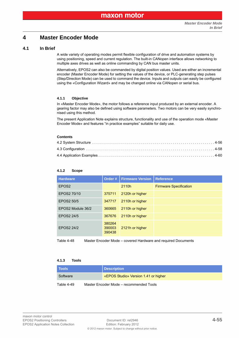
Master Encoder ModeIn Brief
© 2012 maxon motor. Subject to change without prior notice.
maxon motor controlEPOS2 Positioning Controllers Document ID: rel2946 4-55EPOS2 Application Notes Collection Edition: February 2012
4 Master Encoder Mode
4.1 In BriefA wide variety of operating modes permit flexible configuration of drive and automation systems by using positioning, speed and current regulation. The built-in CANopen interface allows networking to multiple axes drives as well as online commanding by CAN bus master units.
Alternatively, EPOS2 can also be commanded by digital position values. Used are either an incremental encoder (Master Encoder Mode) for setting the values of the device, or PLC-generating step pulses (Step/Direction Mode) can be used to command the device. Inputs and outputs can easily be configured using the «Configuration Wizard» and may be changed online via CANopen or serial bus.
4.1.1 Objective
In «Master Encoder Mode», the motor follows a reference input produced by an external encoder. A gearing factor may also be defined using software parameters. Two motors can be very easily synchro-nised using this method.
The present Application Note explains structure, functionality and use of the operation mode «Master Encoder Mode» and features “in practice examples” suitable for daily use.
Contents
4.2 System Structure . . . . . . . . . . . . . . . . . . . . . . . . . . . . . . . . . . . . . . . . . . . . . . . . . . . . . . . . . . . . . 4-56
4.3 Configuration . . . . . . . . . . . . . . . . . . . . . . . . . . . . . . . . . . . . . . . . . . . . . . . . . . . . . . . . . . . . . . . . 4-58
4.4 Application Examples . . . . . . . . . . . . . . . . . . . . . . . . . . . . . . . . . . . . . . . . . . . . . . . . . . . . . . . . . . 4-60
4.1.2 Scope
Table 4-48 Master Encoder Mode – covered Hardware and required Documents
4.1.3 Tools
Table 4-49 Master Encoder Mode – recommended Tools
Hardware Order # Firmware Version Reference
EPOS2 2110h Firmware Specification
EPOS2 70/10 375711 2120h or higher
EPOS2 50/5 347717 2110h or higher
EPOS2 Module 36/2 360665 2110h or higher
EPOS2 24/5 367676 2110h or higher
EPOS2 24/2380264390003390438
2121h or higher
Tools Description
Software «EPOS Studio» Version 1.41 or higher

Master Encoder ModeSystem Structure
© 2012 maxon motor. Subject to change without prior notice.
maxon motor control4-56 Document ID: rel2946 EPOS2 Positioning Controllers
Edition: February 2012 EPOS2 Application Notes Collection
4.2 System Structure
Figure 4-42 Master Encoder Mode – System Structure
Quadrature Counter
EPOS2 70/10, EPOS2 50/5 & EPOS2 Module 36/2
Table 4-50 Quadrature Counter – EPOS2 70/10, EPOS2 50/5 & EPOS2 Module 36/2
EPOS2 24/5 & EPOS2 24/2
Table 4-51 Quadrature Counter – EPOS2 24/5 & EPOS2 24/2
Table 4-52 Master Encoder Mode – Hardware Description (Digital Inputs)
Channel A Digital Input 8
Channel A\ Digital Input 8\
Channel B Digital Input 7
Channel B\ Digital Input 7\
Digital Position Desired Value (Polarity = 0)
Channel A Digital Input 3
Channel B Digital Input 2
Digital Position Desired Value (Polarity = 0)
ValueEPOS2 70/10EPOS2 50/5
EPOS2 Module 36/2 EPOS2 24/5 EPOS2 24/2
Input Voltage 0…5 VDC 0…5 VDC 0…24 VDC 0…24 VDC
Max. Input Voltage -12…+12 VDC -24…+24 VDC -30…+30 VDC -30…+30 VDC
Logic 0 typical <1.0 V typical <0.8 V typical <1.5 V typical <0.7 V
Logic 1 typical >2.4 V typical >2.0 V typical >3.0 V typical >2.4 V
Max.Input Frequency
5 MHz (differential)2.5 MHz (single-ended)
5 MHz (differential)2.5 MHz (single-ended)
100 kHz 500 kHz

Master Encoder ModeSystem Structure
© 2012 maxon motor. Subject to change without prior notice.
maxon motor controlEPOS2 Positioning Controllers Document ID: rel2946 4-57EPOS2 Application Notes Collection Edition: February 2012
Input Parameter
Table 4-53 Master Encoder Mode – Input Parameter
Output Parameter
Table 4-54 Master Encoder Mode – Output Parameter
Best Practice• Use a scaling factor ≤1 for better behavior. Due to the fact that no interpolation is implemented,
movements with factors >1 will result in bigger position jumps, thus producing current peaks.• Switch off software position limitation and set maximum /minimum position limits to INT32_MAX,
respectively to INT32_MIN!
Name IndexSub-index
Description
Digital Position Scaling Numerator
0x2300 0x02Numerator of the scaling factor.Can be used for electronic gearing or to reduce to input frequency.
Digital Position Scaling Denominator
0x2300 0x03Denominator of the scaling factor.Can be used for electronic gearing or to reduce to input frequency.
Digital Position Polarity 0x2300 0x04Polarity of the direction input. The direction can be changed (0 = positive, 1 = negative).
Digital Position Offset 0x2300 0x05Gives a dynamic displacement in reference to the encoder’s desired position.
Minimum Position Limit 0x607D 0x01Defines the negative position limit for the position demand value.
Maximum Position Limit 0x607D 0x02Defines the positive position limit for the position demand value.
Maximum ProfileVelocity 0x607F 0x00This value is used as velocity limit in a position (or velocity) profile mode.
Maximum Acceleration 0x60C5 0x00Allows to limit the acceleration to prevent mechanical damages. Represents the limit of the other acceleration/deceleration objects.
Name IndexSub-index
Description
Digital Position Desired Value 0x2300 0x01Counter value of the up/down counter.Serves as base for the scaling and limiting functions.
Position Demand Value 0x6062 0x00The Master Encoder Mode’s output after scaling and limiting.It is the setting value for the position regulator.
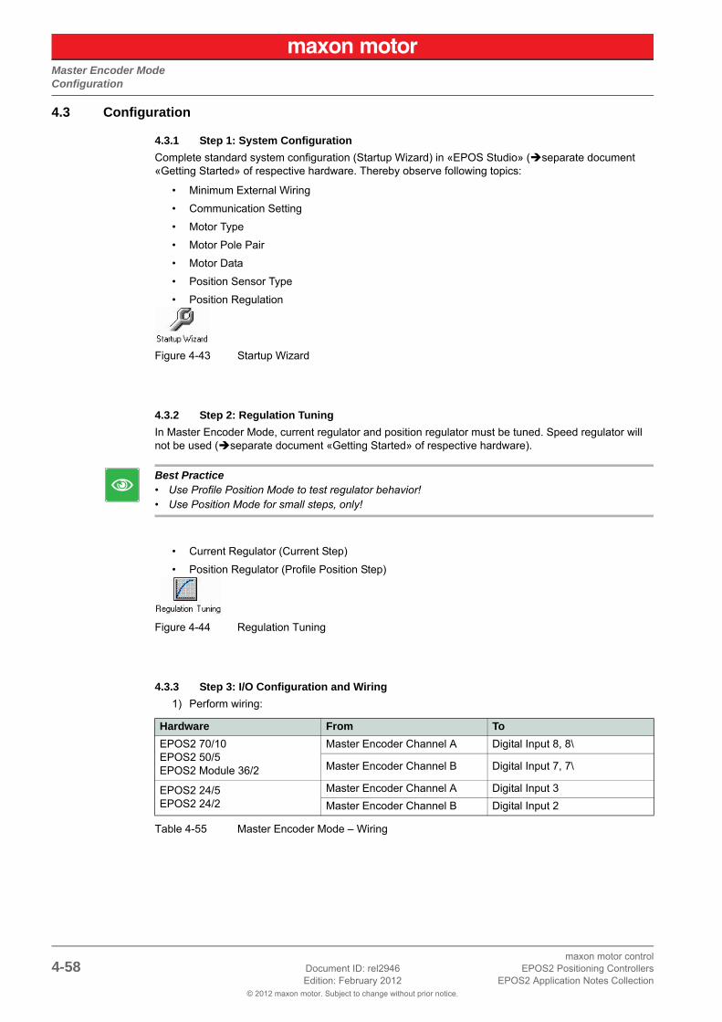
Master Encoder ModeConfiguration
© 2012 maxon motor. Subject to change without prior notice.
maxon motor control4-58 Document ID: rel2946 EPOS2 Positioning Controllers
Edition: February 2012 EPOS2 Application Notes Collection
4.3 Configuration
4.3.1 Step 1: System Configuration
Complete standard system configuration (Startup Wizard) in «EPOS Studio» (separate document «Getting Started» of respective hardware. Thereby observe following topics:
• Minimum External Wiring
• Communication Setting
• Motor Type
• Motor Pole Pair
• Motor Data
• Position Sensor Type
• Position Regulation
Figure 4-43 Startup Wizard
4.3.2 Step 2: Regulation Tuning
In Master Encoder Mode, current regulator and position regulator must be tuned. Speed regulator will not be used (separate document «Getting Started» of respective hardware).
Best Practice• Use Profile Position Mode to test regulator behavior!• Use Position Mode for small steps, only!
• Current Regulator (Current Step)
• Position Regulator (Profile Position Step)
Figure 4-44 Regulation Tuning
4.3.3 Step 3: I/O Configuration and Wiring
1) Perform wiring:
Table 4-55 Master Encoder Mode – Wiring
Hardware From To
EPOS2 70/10EPOS2 50/5EPOS2 Module 36/2
Master Encoder Channel A Digital Input 8, 8\
Master Encoder Channel B Digital Input 7, 7\
EPOS2 24/5EPOS2 24/2
Master Encoder Channel A Digital Input 3
Master Encoder Channel B Digital Input 2

Master Encoder ModeConfiguration
© 2012 maxon motor. Subject to change without prior notice.
maxon motor controlEPOS2 Positioning Controllers Document ID: rel2946 4-59EPOS2 Application Notes Collection Edition: February 2012
2) Start I/O Configuration Wizard to configure I/Os.
Figure 4-45 Configuration Wizard
3) Configure inputs:
Table 4-56 Configuration of Inputs
4.3.4 Step 4: Master Encoder Mode
Activate and configure Master Encoder Mode using «EPOS Studio».
Figure 4-46 Master Encoder Mode – Configuration
4.3.5 Step 5: Save all Parameters
1) Click right on used node (Navigation Window -> Workspace or Communication).
2) Click menu item ¤Save All Parameter¤.
Hardware Configure… …as…
EPOS2 70/10EPOS2 50/5EPOS2 Module 36/2
Digital Input 7 General Purpose A
Digital Input 8 General Purpose B
any available Digital Input Enable *1)
any available Digital Output Ready *2)
EPOS2 24/5EPOS2 24/2
Digital Input 2 General Purpose A
Digital Input 3 General Purpose B
any available Digital Input Enable *1)
any available Digital Output Ready *2)
Remarks:*1) In order to clear a fault condition, the device must be reset. Set input “Enable” to active.*2) Output “Ready” can be used to report a fault condition.

Master Encoder ModeApplication Examples
© 2012 maxon motor. Subject to change without prior notice.
maxon motor control4-60 Document ID: rel2946 EPOS2 Positioning Controllers
Edition: February 2012 EPOS2 Application Notes Collection
4.4 Application ExamplesA typical application for the Master Encoder Mode is a dual axes system.
• The master axis is configured, enabled and commanded via the serial interface (RS232, USB or CAN bus) and is working in “ProfilePosition Mode” or “Profile Velocity Mode”.
• The slave axis is working in “Master Encoder Mode”.
• The CAN bus interface is only used for configuration, monitoring and enabling.
• The set values for the slave axis are calculated using the encoder signals of the master axis.
Figure 4-47 Master Encoder Mode – Application Example: Dual Axes System
Calculation of Velocity of Slave Axis
The velocity of the slave axis is not only defined by the scaling factor, but also by the ratio of the encoder resolution of the master and slave axes.
[pulses per turn]
[rpm]
VelocitySlaveAxis VelocityMasterAxis
EncResMasterAxis
EncResSlaveAxis-------------------------------------------- Polarity 1 1–,[ ]
ScalingNumeratorSlaveAxis
ScalingDenominatorSlaveAxis-----------------------------------------------------------------------------⋅ ⋅ ⋅=
EncRes
Velocity

Master Encoder ModeApplication Examples
© 2012 maxon motor. Subject to change without prior notice.
maxon motor controlEPOS2 Positioning Controllers Document ID: rel2946 4-61EPOS2 Application Notes Collection Edition: February 2012
Limiting Factors
Maximal permitted Motor SpeedBelow figures represent theoretical achievable speeds. For applicable maximum permissible speed of the employed motor catalog motor data!
Main limiting factor is the input frequency of the encoder signals.
Table 4-57 Master Encoder Mode – Limiting Factors
NoteHigher velocities can be reached by increasing the scaling factor >1. Thereby consider applicable restrictions (“Best Practice” on page 4-57).
Master AxisEncoder
[pulse/turn]
Slave AxisMax. Input Frequency
Master AxisMax. Velocity [rpm](Scaling Factor 1)
500
EPOS2 70/10differential 5 MHz 600 000
single-ended 2.5 MHz 300 000
EPOS2 50/5differential 5 MHz 600 000
single-ended 2.5 MHz 300 000
EPOS2 Module 36/2differential 5 MHz 600 000
single-ended 2.5 MHz 300 000
EPOS2 24/5 100 kHz 12 000
EPOS2 24/2 500 kHz 60 000
1000
EPOS2 70/10differential 5 MHz 300 000
single-ended 2.5 MHz 150 000
EPOS2 50/5differential 5 MHz 300 000
single-ended 2.5 MHz 150 000
EPOS2 Module 36/2differential 5 MHz 300 000
single-ended 2.5 MHz 150 000
EPOS2 24/5 differential 100 kHz 6 000
EPOS2 24/2 differential 500 kHz 30 000
5000
EPOS2 70/10differential 5 MHz 60 000
single-ended 2.5 MHz 30 000
EPOS2 50/5differential 5 MHz 60 000
single-ended 2.5 MHz 30 000
EPOS2 Module 36/2differential 5 MHz 60 000
single-ended 2.5 MHz 30 000
EPOS2 24/5 100 kHz 1 200
EPOS2 24/2 500 kHz 3 000
Limitations:– EC motor, sinusoidal commutation: max. 25 000 rpm– EC motor, block commutation: max. 100 000 rpm

Master Encoder ModeApplication Examples
© 2012 maxon motor. Subject to change without prior notice.
maxon motor control4-62 Document ID: rel2946 EPOS2 Positioning Controllers
Edition: February 2012 EPOS2 Application Notes Collection
• • p a g e i n t e n t i o n a l l y l e f t b l a n k • •

Step/Direction ModeIn Brief
© 2012 maxon motor. Subject to change without prior notice.
maxon motor controlEPOS2 Positioning Controllers Document ID: rel2946 5-63EPOS2 Application Notes Collection Edition: February 2012
5 Step/Direction Mode
5.1 In BriefA wide variety of operating modes permit flexible configuration of drive and automation systems by using positioning, speed and current regulation. The built-in CANopen interface allows networking to multiple axes drives as well as online commanding by CAN bus master units.
Alternatively, EPOS2 can also be commanded by digital position values. Used are either an incremental encoder (Master Encoder Mode) for setting the values of the device, or PLC-generating step pulses (Step/Direction Mode) can be used to command the device. Inputs and outputs can easily be configured using the «Configuration Wizard» and may be changed online via CANopen or serial bus.
5.1.1 Objective
In «Step/Direction Mode», the motor axis follows a digital signal step-by-step. This mode can replace stepper motors. It can also be used to control the EPOS2 by a PLC without CAN interface.
The present Application Note explains structure, functionality and use of the operation mode «Step/Direction Mode» and features “in practice examples” suitable for daily use.
Contents
5.2 System Structure . . . . . . . . . . . . . . . . . . . . . . . . . . . . . . . . . . . . . . . . . . . . . . . . . . . . . . . . . . . . . 5-64
5.3 Configuration . . . . . . . . . . . . . . . . . . . . . . . . . . . . . . . . . . . . . . . . . . . . . . . . . . . . . . . . . . . . . . . . 5-66
5.4 Application Examples . . . . . . . . . . . . . . . . . . . . . . . . . . . . . . . . . . . . . . . . . . . . . . . . . . . . . . . . . . 5-68
5.1.2 Scope
Table 5-58 Step/Direction Mode – covered Hardware and required Documents
5.1.3 Tools
Table 5-59 Step/Direction Mode – recommended Tools
Hardware Order # Firmware Version Reference
EPOS2 2110h Firmware Specification
EPOS2 70/10 375711 2120h or higher
EPOS2 50/5 347717 2110h or higher
EPOS2 Module 36/2 360665 2110h or higher
EPOS2 24/5 367676 2110h or higher
EPOS2 24/2380264390003390438
2121h or higher
Tools Description
Software «EPOS Studio» Version 1.41 or higher

Step/Direction ModeSystem Structure
© 2012 maxon motor. Subject to change without prior notice.
maxon motor control5-64 Document ID: rel2946 EPOS2 Positioning Controllers
Edition: February 2012 EPOS2 Application Notes Collection
5.2 System Structure
Figure 5-48 Step/Direction Mode – System Structure
Up/Down Counter
EPOS2 70/10, EPOS2 50/5 & EPOS2 Module 36/2
Table 5-60 Up/Down Counter – EPOS2 70/10, EPOS2 50/5 & EPOS2 Module 36/2
EPOS2 24/5 & EPOS2 24/2
Table 5-61 Up/Down Counter – EPOS2 24/5 & EPOS2 24/2
Table 5-62 Step/Direction Mode – Hardware Description (Digital Inputs)
Step Digital Input 8
Step\ Digital Input 8\
Direction Digital Input 7
Direction\ Digital Input 7\
Digital Position Desired Value (Polarity = 0)
Step Digital Input 3
Direction Digital Input 2
Digital Position Desired Value (Polarity = 0)
ValueEPOS2 70/10EPOS2 50/5
EPOS2 Module 36/2 EPOS2 24/5 EPOS2 24/2
Input Voltage 0…5 VDC 0…5 VDC 0…24 VDC 0…24 VDC
Max. Input Voltage -12…+12 VDC -24…+24 VDC -30…+30 VDC -30…+30 VDC
Logic 0 typically <1.0 V typically <0.8 V typically <1.5 V typical <0.7 V
Logic 1 typically >2.4 V typically >2.0 V typically >3.0 V typical >2.4 V
Max.Input Frequency
5 MHz (differential)2.5 MHz (single-ended)
5 MHz (differential)2.5 MHz (single-ended)
100 kHz 500 kHz

Step/Direction ModeSystem Structure
© 2012 maxon motor. Subject to change without prior notice.
maxon motor controlEPOS2 Positioning Controllers Document ID: rel2946 5-65EPOS2 Application Notes Collection Edition: February 2012
Definition of Direction of Rotation
As seen towards motor output flange, definition is as follows:Direction Input Low: CCWDirection Input High: CW
Input Parameter
Table 5-63 Step/Direction Mode – Input Parameter
Output Parameter
Table 5-64 Step/Direction Mode – Output Parameter
Best Practice• Use a scaling factor ≤1 for better behavior. Due to the fact that no interpolation is implemented,
movements with factors >1 will result in bigger position jumps, thus producing current peaks.• Switch off software position limitation and set maximum /minimum position limits to INT32_MAX,
respectively to INT32_MIN!
Name IndexSub-index
Description
Digital Position Scaling Numerator
0x2300 0x02Numerator of the scaling factor.Can be used for electronic gearing or to reduce to input frequency.
Digital Position Scaling Denominator
0x2300 0x03Denominator of the scaling factor.Can be used for electronic gearing or to reduce to input frequency.
Digital Position Polarity 0x2300 0x04Polarity of the direction input. The direction can be changed (0 = positive, 1 = negative).
Digital Position Offset 0x2300 0x05Gives a dynamic displacement in reference to the encoder’s desired position.
Minimum Position Limit 0x607D 0x01Defines the negative position limit for the position demand value.
Maximum Position Limit 0x607D 0x02Defines the positive position limit for the position demand value.
Maximum ProfileVelocity 0x607F 0x00This value is used as velocity limit in a position (or velocity) profile mode.
Maximum Acceleration 0x60C5 0x00Allows to limit the acceleration to prevent mechanical damages. Represents the limit of the other acceleration/deceleration objects.
Name IndexSub-index
Description
Digital Position Desired Value 0x2300 0x01Counter value of the up/down counter.Serves as base for the scaling and limiting functions.
Position Demand Value 0x6062 0x00The Step/Direction Mode’s output after scaling and limiting.It is the setting value for the position regulator.

Step/Direction ModeConfiguration
© 2012 maxon motor. Subject to change without prior notice.
maxon motor control5-66 Document ID: rel2946 EPOS2 Positioning Controllers
Edition: February 2012 EPOS2 Application Notes Collection
5.3 Configuration
5.3.1 Step 1: System Configuration
Complete standard system configuration (Startup Wizard) in «EPOS Studio» (separate document «Getting Started» of respective hardware. Thereby observe following topics:
• Minimum External Wiring
• Communication Setting
• Motor Type
• Motor Pole Pair
• Motor Data
• Position Sensor Type
• Position Regulation
Figure 5-49 Startup Wizard
5.3.2 Step 2: Regulation Tuning
In Master Encoder Mode, current regulator and position regulator must be tuned. Speed regulator will not be used (separate document «Getting Started» of respective hardware).
Best Practice• Use Profile Position Mode to test regulator behavior!• Use Position Mode for small steps, only!
• Current Regulator (Current Step)
• Position Regulator (Profile Position Step)
Figure 5-50 Regulation Tuning
5.3.3 Step 3: I/O Configuration and Wiring
1) Perform wiring:
Table 5-65 Step/Direction Mode – Wiring
Hardware From To
EPOS2 70/10EPOS2 50/5EPOS2 Module 36/2
Step Digital Input 8, 8\
Direction Digital Input 7, 7\
EPOS2 24/5EPOS2 24/2
Step Digital Input 3
Direction Digital Input 2

Step/Direction ModeConfiguration
© 2012 maxon motor. Subject to change without prior notice.
maxon motor controlEPOS2 Positioning Controllers Document ID: rel2946 5-67EPOS2 Application Notes Collection Edition: February 2012
2) Start I/O Configuration Wizard to configure I/Os.
Figure 5-51 Configuration Wizard
3) Configure inputs:
Table 5-66 Configuration of Inputs
5.3.4 Step 4: Step/Direction Mode
Activate and configure Step/Direction Mode using «EPOS Studio».
Figure 5-52 Step/Direction Mode – Configuration
5.3.5 Step 5: Save all Parameters
1) Click right on used node (Navigation Window -> Workspace or Communication).
2) Click menu item ¤Save All Parameter¤.
Hardware Configure… …as…
EPOS2 70/10EPOS2 50/5EPOS2 Module 36/2
Digital Input 7 General Purpose A
Digital Input 8 General Purpose B
any available Digital Input Enable *1)
any available Digital Output Ready *2)
EPOS2 24/5EPOS2 24/2
Digital Input 2 General Purpose A
Digital Input 3 General Purpose B
any available Digital Input Enable *1)
any available Digital Output Ready *2)
Remarks:*1) In order to clear a fault condition, the device must be reset. Set input “Enable” to active.*2) Output “Ready” can be used to report a fault condition.
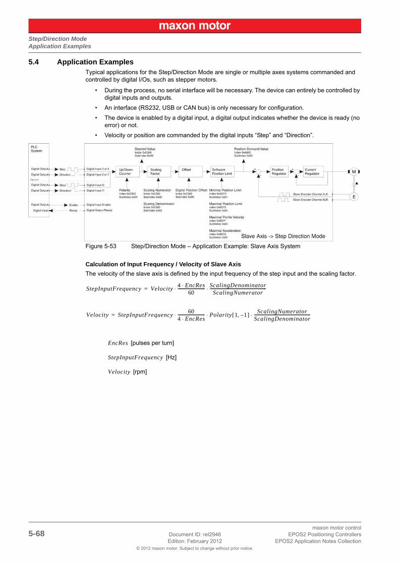
Step/Direction ModeApplication Examples
© 2012 maxon motor. Subject to change without prior notice.
maxon motor control5-68 Document ID: rel2946 EPOS2 Positioning Controllers
Edition: February 2012 EPOS2 Application Notes Collection
5.4 Application ExamplesTypical applications for the Step/Direction Mode are single or multiple axes systems commanded and controlled by digital I/Os, such as stepper motors.
• During the process, no serial interface will be necessary. The device can entirely be controlled by digital inputs and outputs.
• An interface (RS232, USB or CAN bus) is only necessary for configuration.
• The device is enabled by a digital input, a digital output indicates whether the device is ready (no error) or not.
• Velocity or position are commanded by the digital inputs “Step” and “Direction”.
Figure 5-53 Step/Direction Mode – Application Example: Slave Axis System
Calculation of Input Frequency / Velocity of Slave Axis
The velocity of the slave axis is defined by the input frequency of the step input and the scaling factor.
[pulses per turn]
[Hz]
[rpm]
StepInputFrequency Velocity4 EncRes⋅
60--------------------------- ScalingDenominator
ScalingNumerator--------------------------------------------------------⋅ ⋅=
Velocity StepInputFrequency60
4 EncRes⋅--------------------------- Polarity 1 1–,[ ] ScalingNumerator
ScalingDenominator--------------------------------------------------------⋅ ⋅ ⋅=
EncRes
StepInputFrequency
Velocity

Step/Direction ModeApplication Examples
© 2012 maxon motor. Subject to change without prior notice.
maxon motor controlEPOS2 Positioning Controllers Document ID: rel2946 5-69EPOS2 Application Notes Collection Edition: February 2012
Limiting Factors
Maximal permitted Motor SpeedBelow figures represent theoretical achievable speeds. For applicable maximum permissible speed of the employed motor catalog motor data!
The primary limiting factor is the step signal’s input frequency. Below table shows the maximum velocity of the slave axis assuming a scaling factor of 1. To command higher velocities, the scaling factor can be used to reduce the step input’s input frequency.
Table 5-67 Step/Direction Mode – Limiting Factors
NoteHigher velocities can be reached by increasing the scaling factor >1. Thereby consider applicable restrictions (“Best Practice” on page 5-65).
Encoder[pulse/turn]
Max. Step Input FrequencyMax. Velocity [rpm](Scaling Factor 1)
500
EPOS2 70/10differential 5 MHz 150 000
single-ended 2.5 MHz 75 000
EPOS2 50/5differential 5 MHz 150 000
single-ended 2.5 MHz 75 000
EPOS2 Module 36/2differential 5 MHz 150 000
single-ended 2.5 MHz 75 000
EPOS2 24/5 100 kHz 3 000
EPOS2 24/2 500 kHz 15 000
1000
EPOS2 70/10differential 5 MHz 75 000
single-ended 2.5 MHz 37 500
EPOS2 50/5differential 5 MHz 75 000
single-ended 2.5 MHz 37 500
EPOS2 Module 36/2differential 5 MHz 75 000
single-ended 2.5 MHz 37 500
EPOS2 24/5 differential 100 kHz 1 500
EPOS2 24/2 differential 500 kHz 7 500
5000
EPOS2 70/10differential 5 MHz 15 000
single-ended 2.5 MHz 7 500
EPOS2 50/5differential 5 MHz 15 000
single-ended 2.5 MHz 7 500
EPOS2 Module 36/2differential 5 MHz 15 000
single-ended 2.5 MHz 7 500
EPOS2 24/5 100 kHz 300
EPOS2 24/2 500 kHz 1 500
Limitations:– EC motor, sinusoidal commutation: max. 25 000 rpm– EC motor, block commutation: max. 100 000 rpm

Step/Direction ModeApplication Examples
© 2012 maxon motor. Subject to change without prior notice.
maxon motor control5-70 Document ID: rel2946 EPOS2 Positioning Controllers
Edition: February 2012 EPOS2 Application Notes Collection
• • p a g e i n t e n t i o n a l l y l e f t b l a n k • •

Interpolated Position ModeIn Brief
© 2012 maxon motor. Subject to change without prior notice.
maxon motor controlEPOS2 Positioning Controllers Document ID: rel2946 6-71EPOS2 Application Notes Collection Edition: February 2012
6 Interpolated Position Mode
6.1 In BriefA wide variety of operating modes permit flexible configuration of drive and automation systems by using positioning, speed and current regulation. The built-in CANopen interface allows networking to multiple axes drives as well as online commanding by CAN bus master units.
For fast communication with several EPOS devices, use the CANopen protocol. The individual devices of a network are commanded by a CANopen master.
6.1.1 Objective
«Interpolated Position Mode» is used to control multiply coordinated axes or a single axis with the need for time interpolation of setpoint data. The trajectory is calculated by the CANopen master and passed on to the controller's interpolated position buffer as a set of points. The controller then reads the points from the buffer and performs linear or cubic interpolation between them.
The present Application Note explains structure, functionality and use of the operation mode «Interpo-lated Position Mode» and features “in practice examples” suitable for daily use.
Contents
6.2 In Detail. . . . . . . . . . . . . . . . . . . . . . . . . . . . . . . . . . . . . . . . . . . . . . . . . . . . . . . . . . . . . . . . . . . . . 6-72
6.3 IPM Implementation by maxon . . . . . . . . . . . . . . . . . . . . . . . . . . . . . . . . . . . . . . . . . . . . . . . . . . . 6-75
6.4 Configuration . . . . . . . . . . . . . . . . . . . . . . . . . . . . . . . . . . . . . . . . . . . . . . . . . . . . . . . . . . . . . . . . 6-87
6.1.2 Scope
Table 6-68 Interpolated Position Mode – covered Hardware and required Documents
6.1.3 Tools
Table 6-69 Interpolated Position Mode – recommended Tools
Hardware Order # Firmware Version Reference (page 1-11)
EPOS2 2101hFirmware SpecificationCommunication Guide ([ 6 ])
EPOS2 70/10 375711 2120h or higher
EPOS2 50/5 347717 2110h or higher
EPOS2 Module 36/2 360665 2110h or higher
EPOS2 24/2380264390003390438
2121h or higher
CANopen NetworkDS-301 Version 4.02 ([ 1 ])DSP-402 Version 2.0 ([ 2 ])
Tools Description
Software «EPOS Studio» Version 1.41 or higher

Interpolated Position ModeIn Detail
© 2012 maxon motor. Subject to change without prior notice.
maxon motor control6-72 Document ID: rel2946 EPOS2 Positioning Controllers
Edition: February 2012 EPOS2 Application Notes Collection
6.2 In Detail
6.2.1 Introductory Analogy
Let us assume: In a company, a department manager must convert the department goals into clear tasks for his coworkers. It must be considered that the individual tasks oftentimes stand to each other in close interdependency. Thus, the department manager will gladly count on capable coworkers, being able to solve their tasks even on basis on just substantial data. For the solution’s quality, it is in particular important that it…
a) is factually correct; i.e. it will not require further checks,
b) will be finished in time and
c) was reached efficiently.
The functionality «Interpolated Position Mode» values up the positioning controller EPOS2 to such a “capable coworker” in a superordinate drive system. Following, the thesis’ description:
In a drive system, normally several axes must be moved according to the guidelines of a central control-ler. This can take place in the way that each local axis controller receives the next target position in real time – in time and at the same time to each sampling instance. This strategy has the advantage that the local controllers need only little intelligence. However, the central controller must compute target posi-tions for every sampling interval and must communicate the data to every local controller in real time.
As to above analogy…
• it would be favorable if only few, but substantial points of the driving profiles would be considered,
• it would be desirable if the corresponding data could be transmitted to the local controller not necessarily at the same time, but rather in time.
Both goals can be reached by interpolation and data buffering.
First, the central controller decides which points of the local trajectories are substantial for a synchro-nized total movement. Then, each relevant point of the local trajectories is supplemented with the corre-sponding velocity and time – i.e. triplicates of the kind (position, velocity, time = PVT) are formed. These triplicates are then transferred to the associated axis controllers, in time. Each local controller pos-sesses a buffer to receive these data. EPOS2’s buffer covers 64 locations for triplicates. The data trans-fer to the EPOS2 is in time as long as the buffer contains 1 to 64 new triplicates.
In EPOS2, local position regulation is sampled with a rate of 1 kHz. Thus, requiring 1000 target positions per second in real time. These target positions are computed in EPOS2 by means of interpolation. Each triplicate forms a base point with the abscissa time and the two ordinates position and velocity. There-fore, two triplicates deliver two abscissas and four corresponding ordinates, permitting an interpolation polynomial of third order unambiguously computed between the two base points. The computation, as well as the evaluation of the polynomial in the local sampling clock, take place on basis of simple arith-metic and are efficiently executed by the EPOS2.
The endpoint of the polynomial [n] forms the starting point of the polynomial [n+1]. Therefore, it is suffi-cient to indicate only the relative time in a data triplicate (i.e. the length of the time interval). In fact, with the EPOS2, the time distance of two base points can be selected between 1 ms and 255 ms. This inter-val length can be adapted by the central controller to realize the desired total movement.
With the goal of all controllers within the drive system referring to the same time base, the central con-troller initiates periodically a time check. This time synchronization takes place with the EPOS2 via the “SYNC Time Stamp Mechanism”.
Finally, Interpolated Position Mode can be qualified as follows: The resulting smooth driving profiles, as well as the close temporal synchronization allow to superpose several high-dynamic single movements to a precise total movement in a drive system.
6.2.2 General Description
The Interpolated Position Mode described in the CiA specification DSP402V3.0 is a general case. The objects are well-specified or a linear interpolation (PT). The interpolation type can also be extended by manufacturer-specific algorithms (selectable by «Interpolation Submode Selection», Object 0x60C0).

Interpolated Position ModeIn Detail
© 2012 maxon motor. Subject to change without prior notice.
maxon motor controlEPOS2 Positioning Controllers Document ID: rel2946 6-73EPOS2 Application Notes Collection Edition: February 2012
6.2.3 Spline Interpolation
For the Interpolated Position Mode, the interpolation type is a cubic spline interpolation. The higher-level trajectory planner sends a set of interpolation points by PVT reference point. Each PVT reference point contains information on position, velocity and time of a profile segment end point. The trajectory genera-tor of the drive performs a third order interpolation between the actual and the next reference point.
Figure 6-54 Interpolated Position Mode – PVT Principle
From two successive PVT reference points, the interpolation parameters a, b, c and d can be calculated:
d = P[t0] = P[n]
c = V[t0] = V[n]
b = T-2[n] * (3 * (P[n] – P[n-1]) + T[n] * (V[n] + 2 * V[n-1]))
a = T-3[n] * (2 * (P[n] – P[n-1]) + T[n] * (V[n] + V[n-1]))
The interpolated values for position, velocity and (possibly also) acceleration will be calculated as fol-lows:
P(t) = a * (t – t0)3 + b * (t – t0)2 + c * (t – t0) + d
V(t) = 3a * (t – t0)2 + 2b * (t – t0) + c
A(t) = 6a * (t – t0) + 2b
t0: time of interpolation segment end ( in this calculation t0 is greater then t!)
It is not mandatory that the time intervals are identical.

Interpolated Position ModeIn Detail
© 2012 maxon motor. Subject to change without prior notice.
maxon motor control6-74 Document ID: rel2946 EPOS2 Positioning Controllers
Edition: February 2012 EPOS2 Application Notes Collection
6.2.4 SYNC Time Stamp Mechanism
Can be used to synchronize the motion clock of the drive with a master clock in the network.
Figure 6-55 Interpolated Position Mode – Clock Synchronization
The synchronisation method is similar to IEEE 1588 and uses the CANopen DSP301 SYNC Service (COB-Id 0x80) and “High Resolution Time Stamp” on page 6-79.
The SYNC Frame will be transmitted periodically by the SYNC master. The exact transmitting time (Tm1) may be stored by latching an internal 1 us timer. The reception time (Td1) of the SYNC message will be stored by latching the device-internal motion clock timer. As a follow-up, the measured transmit-ting time (Tm1) will be sent to the drive using the High Resolution Time Stamp. The device then adjusts its internal motion clock time in relation to the time latched in the last SYNC.
By sending a CANopen DSP301 TIME Service (by default COB-Id 0x100, or defined as to “COB-ID Time Stamp Object” on page 6-79), the device-internal motion clock timer can be reset to “0”.

Interpolated Position ModeIPM Implementation by maxon
© 2012 maxon motor. Subject to change without prior notice.
maxon motor controlEPOS2 Positioning Controllers Document ID: rel2946 6-75EPOS2 Application Notes Collection Edition: February 2012
6.3 IPM Implementation by maxonThe Interpolated Position Mode is implemented in the EPOS2 as an additional operational mode (oper-ating mode 7 as specified in DSP 402V3.0).
Figure 6-56 Interpolated Position Mode – Interpolation Controller
6.3.1 Interpolated Position Data Buffer
PVT reference points will be sent in a manufacturer-specific 64 bit data record of a complex data struc-ture to a FIFO object.
6.3.1.1 Definition of complex Data Structure 0x0040
Table 6-70 Interpolated Position Mode – IPM Data Buffer Structure
MSB LSB
Time (unsigned8) Velocity (signed24) Position (signed32)
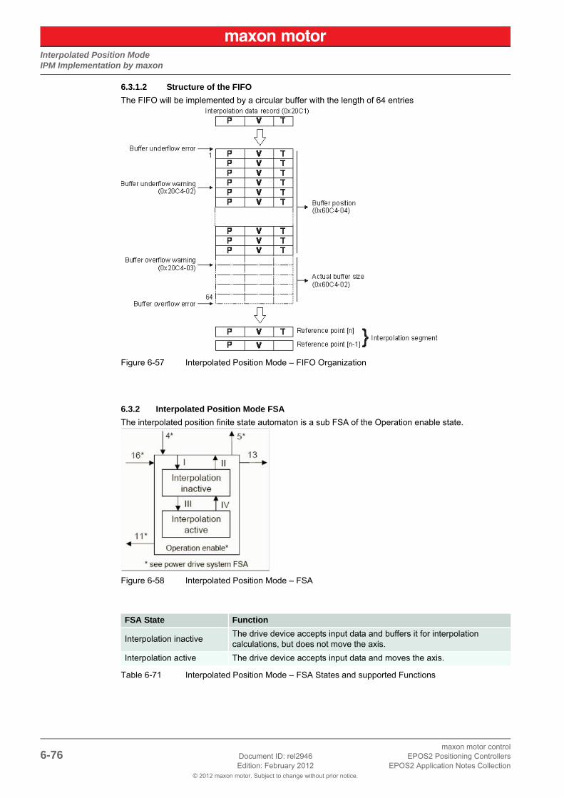
Interpolated Position ModeIPM Implementation by maxon
© 2012 maxon motor. Subject to change without prior notice.
maxon motor control6-76 Document ID: rel2946 EPOS2 Positioning Controllers
Edition: February 2012 EPOS2 Application Notes Collection
6.3.1.2 Structure of the FIFO
The FIFO will be implemented by a circular buffer with the length of 64 entries
Figure 6-57 Interpolated Position Mode – FIFO Organization
6.3.2 Interpolated Position Mode FSA
The interpolated position finite state automaton is a sub FSA of the Operation enable state.
Figure 6-58 Interpolated Position Mode – FSA
Table 6-71 Interpolated Position Mode – FSA States and supported Functions
FSA State Function
Interpolation inactiveThe drive device accepts input data and buffers it for interpolation calculations, but does not move the axis.
Interpolation active The drive device accepts input data and moves the axis.

Interpolated Position ModeIPM Implementation by maxon
© 2012 maxon motor. Subject to change without prior notice.
maxon motor controlEPOS2 Positioning Controllers Document ID: rel2946 6-77EPOS2 Application Notes Collection Edition: February 2012
Table 6-72 Interpolated Position Mode – Transition Events and Actions
6.3.3 Configuration Parameters
Table 6-73 Interpolated Position Mode – Configuration Parameters
6.3.4 Commanding Parameters
Table 6-74 Interpolated Position Mode – Commanding Parameters
Transition Event Action
I ip mode selected (object 6060h, page 6-86) clear data buffer
II ip mode not selected (object 6060h, page 6-86) none
III enable ip mode: set Controlword bit 4 to 1 none
IVdisable ip mode: set Controlword bit 4 to 0
or ip data record with time = 0none
Parameter Index Description
Interpolation Sub Mode Selection
0x60C0 Indicates the actually chosen interpolation mode.
Interpolation Time Period 0x60C2 Indicates the configured interpolation cycle time.
Interpolation Data Configuration
0x60C4Provides information on configuration and state of the buffer. It can also be used to clear the buffer.
Software Position Limit 0x607D
Contains the sub-parameters «Minimal Position Limit» and «Maximal Position Limit» that define the absolute position limits or the position demand value. A new target position will be checked against these limits
Position Window 0x6067
Permits definition of a position range around a target position to be regarded as valid. If the drive is within this area for a specified time, the related Statusword control bit 10 «Target reached» is set.
Position Window Time 0x6068 Defines the time or the position window.
Profile Velocity 0x6081If calculated velocity of the interpolation exceeds this value, a warning bit in Interpolation Buffer Status Word will be set.
Profile Acceleration 0x6083If calculated acceleration of the interpolation exceeds this value, a warning bit in Interpolation Buffer Status Word will be set.
Maximal Profile Velocity 0x607FIf calculated velocity of the interpolation exceeds this value, an error bit in Interpolation Buffer Status Word will be set and the device will switch to Fault reaction state.
Maximal Acceleration 0x60C5If calculated acceleration of the interpolation exceeds this value, an error bit in Interpolation Buffer Status Word will be set and the device will switch to Fault reaction state.
Interpolation Status 0x20C4The Interpolation buffer underflow/overflow warning level is configured in subindex 2 and 3.
Parameter Index Description
Controlword 0x6040The mode will be controlled by a write access to the Controlword’s mode-dependent bits.
Interpolation Data Record 0x20C1Contains a FIFO to feed PVT reference points to the data buffer.

Interpolated Position ModeIPM Implementation by maxon
© 2012 maxon motor. Subject to change without prior notice.
maxon motor control6-78 Document ID: rel2946 EPOS2 Positioning Controllers
Edition: February 2012 EPOS2 Application Notes Collection
Controlword (Interpolated Position Mode-specific Bits)
Table 6-75 Interpolated Position Mode – Controlword
Table 6-76 Interpolated Position Mode – Controlword Bits
6.3.5 Output Parameters
Table 6-77 Interpolated Position Mode – Output Parameters
Statusword (Interpolated Position Mode-specific Bits)
Table 6-78 Interpolated Position Mode – Statusword
Table 6-79 Interpolated Position Mode – Statusword Bits
Bit 15…9 Bit 8 Bit 7 Bit 6, 5 Bit 4 Bit 3…0
FwSpec Halt FwSpec reserved (0)Enable ip mode
FwSpec
Name Value Description
Enable ip mode0 Interpolated position mode inactive
1 Interpolated position mode active
Halt0 Execute instruction of bit 4
1 Stop axis with profile deceleration
Parameter Index Description
Interpolation status 0x20C4 The mode’s statusword is placed in subindex 1 of this object.
Statusword 0x6041 Mode state can be observed by Statusword bits.
Position Demand Value 0x6062The output of the trajectory generator – it is used as input for the position control function.
Bit 15, 14 Bit 13 Bit 12 Bit 11 Bit 10 Bit 9…0
FwSpec reserved ip mode active FwSpecTarget reached
FwSpec
Name Value Description
Target reached
0Halt = 0: Target Position not (yet) reachedHalt = 1: Axle decelerates
1Halt = 0: Target Position reachedHalt = 1: Velocity of axle is 0
ip mode active0 ip mode inactive
1 ip mode active

Interpolated Position ModeIPM Implementation by maxon
© 2012 maxon motor. Subject to change without prior notice.
maxon motor controlEPOS2 Positioning Controllers Document ID: rel2946 6-79EPOS2 Application Notes Collection Edition: February 2012
6.3.6 Object Description in Detail
6.3.6.1 COB-ID Time Stamp Object
Description
Defines the COB-ID of the Time Stamp Object (TIME). In EPOS2, this value is immutable.
6.3.6.2 High Resolution Time Stamp
Description
Contains the timestamp of the last received SYNC Object [1us]. The resolution of the device internal motion clock timer depend on the selected CAN bitrate (bit time) e.g. 1 us at 1Mbit/s. After a write access to this object, the EPOS2 calculates the difference between the received timestamp and the internal latched timestamp of the SYNC Object. This time difference is used as correction for the IPM time calculations.
Name COB-ID Time Stamp Object
Index 0x1012
Subindex 0x00
Type UNSIGNED32
Access RW
Default Value 0x00000100
Value Range 0x00000100 0x00000100
PDO Mapping no
Name High Resolution Time Stamp
Index 0x1013
Subindex 0x00
Type UNSIGNED32
Access RW
Default Value –
Value Range – –
PDO Mapping yes

Interpolated Position ModeIPM Implementation by maxon
© 2012 maxon motor. Subject to change without prior notice.
maxon motor control6-80 Document ID: rel2946 EPOS2 Positioning Controllers
Edition: February 2012 EPOS2 Application Notes Collection
6.3.6.3 Interpolation Data Record
Description
Sets PVT reference points in the interpolated position mode in the cubic spline interpolation sub-mode. The position is given absolute in [Position units], typically [qc]), the velocity is given in [Velocity units], typically [rpm]), and the time is given in [ms]. The object structure is defined in “Interpolated Position Data Buffer” on page 6-75.
Remarks
Normally used to feed PVT reference points to the drive while a PVT motion is executing. Therefore the object may be mapped to a RxPDO with transmission type of 255 (asynchronous).
In the Interpolation active state at least two data records have to be in the FIFO. Otherwise a Queue underflow Emergency will be launched and the drive changes to Fault reaction state.
A data record with time = 0 changes the state to Interpolation inactive without any error.
6.3.6.4 Interpolation Status
Description
Provides access to status information on the IP input data buffer.
Table 6-80 Interpolation Buffer Status Word
Name Interpolation Data Record
Index 0x20C1
Subindex 0x00
Type complex data structure 0x0040
Access WO
Default Value –
Value Range – –
PDO Mapping yes
Name Interpolation Status
Index 0x20C4
Number of entries 0x03
Name Interpolation Buffer Status
Index 0x20C4
Subindex 0x01
Type UNSIGNED16
Access RO
Default Value –
Value Range – –
PDO Mapping yes
Bit 15 Bit 14 Bit 13…12 Bit 11…8 Bit 7…4 Bit 3…0
IP Mode active Buffer enabled reserved (0)IPM buffer errors
reserved (0)IPM buffer warnings

Interpolated Position ModeIPM Implementation by maxon
© 2012 maxon motor. Subject to change without prior notice.
maxon motor controlEPOS2 Positioning Controllers Document ID: rel2946 6-81EPOS2 Application Notes Collection Edition: February 2012
Table 6-81 Interpolation Buffer Status Bits
Description
Gives the lower signalization level of the data input FIFO. If the filling level is below this border the warn-ing flag (bit 0) in the Interpolation buffer status will be set.
Name Bit
Va
lue
Description
Underflow Warning
00 No buffer underflow warning
1 Buffer underflow warning level (0x20C4-2) is reached
Overflow Warning
10 No buffer overflow warning
1 Buffer overflow warning level (0x20C4-3) is reached
Velocity Warning
20 No profile velocity violation detected
1 IPM velocity greater than profile velocity (0x6081) detected
Acceleration Warning
30 No profile acceleration violation detected
1 IPM acceleration greater than profile acceleration (0x6083) detected
Underflow Error 80 No buffer underflow error
1 Buffer underflow error (trajectory abort)
Overflow Error 90 No buffer overflow error
1 Buffer overflow error (trajectory abort)
Velocity Error 100 No maximal profile velocity error
1 IPM velocity greater than maximal profile velocity (0x607F) detected
Acceleration Error
11
0 No maximal profile acceleration error
1IPM acceleration greater than maximal profile acceleration (0x60C5) detected
Buffer enabled 140 Disabled access to the input buffer
1 Access to the input buffer enabled
IP Mode active 150 IP mode inactive (same as bit 12 in statusword)
1 IP mode active
Name Interpolation Buffer Underflow Warning
Index 0x20C4
Subindex 0x02
Type UNSIGNED16
Access RW
Default Value 4
Value Range 0 63
PDO Mapping no

Interpolated Position ModeIPM Implementation by maxon
© 2012 maxon motor. Subject to change without prior notice.
maxon motor control6-82 Document ID: rel2946 EPOS2 Positioning Controllers
Edition: February 2012 EPOS2 Application Notes Collection
Description
Gives the higher signalization level of the data input FIFO. If the filling level is above this border the warning flag (bit 1) in the Interpolation buffer status will be set.
6.3.6.5 Interpolation Sub Mode Selection
Description
Indicates the actually chosen interpolation mode.
Table 6-82 Interpolation Sub Mode Selection – Definition
Name Interpolation Buffer Overflow Warning
Index 0x20C4
Subindex 0x03
Type UNSIGNED16
Access RW
Default Value 60
Value Range 1 64
PDO Mapping no
Name Interpolation Sub Mode Selection
Index 0x60C0
Subindex 0x00
Type INTEGER16
Access RW
Default Value -1
Value Range -1 -1
PDO Mapping no
Value Description
-32 768…-2 Manufacturer-specific (reserved)
-1 cubic spline interpolation (PVT)
0 Linear interpolation (not yet implemented)
1…32 767 reserved

Interpolated Position ModeIPM Implementation by maxon
© 2012 maxon motor. Subject to change without prior notice.
maxon motor controlEPOS2 Positioning Controllers Document ID: rel2946 6-83EPOS2 Application Notes Collection Edition: February 2012
6.3.6.6 Interpolation Time Period
Description
Indicates the configured interpolation cycle time. The interpolation time period (subindex 0x01) value is given in 10interpolation time index per second. The interpolation time index (subindex 0x02) is dimensionless.
6.3.6.7 Interpolation Data Configuration
Description
Provides the maximal buffer size and is given in interpolation data records.
Name Interpolation Time Period
Index 0x60C2
Number of entries 0x02
Name Interpolation Time Period Value
Index 0x60C2
Subindex 0x01
Type UNSIGNED8
Access RW
Default Value 1
Value Range 1 1
PDO Mapping no
Name Interpolation Time Index
Index 0x60C2
Subindex 0x01
Type INTEGER8
Access RW
Default Value -3
Value Range -3 -3
PDO Mapping no
Name Interpolation Data Configuration
Index 0x60C4
Number of entries 0x06
Name Maximum Buffer Size
Index 0x60C4
Subindex 0x01
Type UNSIGNED32
Access RO
Default Value –
Value Range 64 64
PDO Mapping no

Interpolated Position ModeIPM Implementation by maxon
© 2012 maxon motor. Subject to change without prior notice.
maxon motor control6-84 Document ID: rel2946 EPOS2 Positioning Controllers
Edition: February 2012 EPOS2 Application Notes Collection
Description
Provides the actual free buffer size and is given in interpolation data records.
Description
The value 0 indicates a FIFO buffer organization.
Table 6-83 Buffer Organization – Definition
Description
Provides used buffer space and is given in interpolation data records. Writing to this object has no effect.
Name Actual Buffer Size
Index 0x60C4
Subindex 0x02
Type UNSIGNED32
Access RO
Default Value –
Value Range 0 64
PDO Mapping yes
Name Buffer Organization
Index 0x60C4
Subindex 0x03
Type UNSIGNED8
Access RW
Default Value –
Value Range – –
PDO Mapping no
Value Description
0 FIFO buffer
1 Ring buffer (not supported)
2…255 reserved
Name Buffer Position
Index 0x60C4
Subindex 0x04
Type UNSIGNED16
Access RW
Default Value 0
Value Range 0 64
PDO Mapping no

Interpolated Position ModeIPM Implementation by maxon
© 2012 maxon motor. Subject to change without prior notice.
maxon motor controlEPOS2 Positioning Controllers Document ID: rel2946 6-85EPOS2 Application Notes Collection Edition: February 2012
Description
Interpolation data record size is 8 bytes.
Description
If 0 is written, the data buffer is cleared and the access to it is denied. If 1 is written, the access to the data buffer is enabled.
Related Objects
“Interpolation Status” on page 6-80
Table 6-84 Buffer Clear – Definition
Name Size of Data Record
Index 0x60C4
Subindex 0x05
Type UNSIGNED8
Access WO
Default Value –
Value Range 8 8
PDO Mapping no
Name Buffer Clear
Index 0x60C4
Subindex 0x06
Type UNSIGNED8
Access WO
Default Value 0
Value Range 0 1
PDO Mapping no
Value Description
0 Clear input buffer (and all data records) access disabled
1 Enable access to the input buffer for the drive functions
2…255 reserved

Interpolated Position ModeIPM Implementation by maxon
© 2012 maxon motor. Subject to change without prior notice.
maxon motor control6-86 Document ID: rel2946 EPOS2 Positioning Controllers
Edition: February 2012 EPOS2 Application Notes Collection
6.3.7 Typical IPM Commanding Sequence
Table 6-85 Interpolated Position Mode – typical Command Sequence
As long as the interpolation is active, feeding of new reference points is the main task. To minimize the communication overhead, it might make sense to map the “Interpolation Data Record” in a (asynchro-nous) receive PDO. If the “Interpolation Buffer Status” is mapped to an event trigger transmit PDO (pos-sibly along with the Statusword), processing of reference point feeding can easier be implemented.
Object Name Object User Value [Default Value]
Modes of Operation 0x6060-00 0x07 (Interpolated Position Mode)
Max. Following ErrorMin. Position LimitMax. Position LimitMax. Profile VelocityMax. AccelerationProfile VelocityProfile AccelerationQuick Stop Deceleration
0x6065-000x607D-010x607D-020x607F-000x60C5-000x6081-000x6083-000x6084-00
Application specific [2000 qc]Application specific [-2147483648 qc]Application specific [2147483647 qc]Motor specific [25000 rpm]Application specific [4294967295 rpm/s]Application specific [1000 rpm]Application specific [10000 rpm/s]Application specific [10000 rpm/s
Controlword (Shutdown)Controlword (SwitchOn)
0x6040-000x6040-00
0x00060x000F
Buffer Clear 0x60C4-00 0x01
Interpolation Data Record 0x20C1-00 Reference points (PVT), minimum 2 points!
Controlword (enable ip mode) 0x6040-00 0x001F
if (Interpolation Buffer Status)do Interpolation Data Recorduntil (Interpolation Buffer Status)
0x20C4-010x20C1-000x20C4-01
Bit 0 == 1 (Underflow Warning)Reference point (PVT)Bit 1 == 1 (Overflow Warning)
Interpolation Data Record 0x20C1-00 Reference point (PVT) with time = 0

Interpolated Position ModeConfiguration
© 2012 maxon motor. Subject to change without prior notice.
maxon motor controlEPOS2 Positioning Controllers Document ID: rel2946 6-87EPOS2 Application Notes Collection Edition: February 2012
6.4 Configuration1) Complete standard system configuration (Startup Wizard) in «EPOS Studio» (separate docu-
ment «Getting Started» of respective hardware.
2) Start CANopen Wizard.
3) Select “Restore Default COB-IDs”.
4) Enter settings for “Receive PDO1”:
a) Tick “PDO is valid”.
b) Set Transmission Type to “Asynchronous”.
c) Click ¤Next¤.
Figure 6-59 CANopen Wizard #5
5) Change Mapping:
a) Delete all mapped objects.
b) Select “Interpolation Data Record” from Mappable Objects and add to Mapped Objects No 1 using ¤>>¤.
c) Click ¤OK¤.
Figure 6-60 Change Mapping Receive PDO1
6) Enter settings for “Transmit PDO1”:
a) Tick “PDO is valid”.
b) Set Transmission Type to “Asynchronous”.
c) Set Inhibit Time (e.g. 5.0 ms).

Interpolated Position ModeConfiguration
© 2012 maxon motor. Subject to change without prior notice.
maxon motor control6-88 Document ID: rel2946 EPOS2 Positioning Controllers
Edition: February 2012 EPOS2 Application Notes Collection
d) Click ¤Next¤.
Figure 6-61 CANopen Wizard #13
7) Change Mapping:
a) Delete all mapped objects.
b) Select “Interpolation Buffer Status” from Mappable Objects and add to Mapped Objects No 1 using ¤>>¤.
c) Select “StatusWord” from Mappable Objects and add to Mapped Objects No 2 using ¤>>¤.
d) Click ¤OK¤.
Figure 6-62 Change Mapping Transmit PDO1
8) Complete CANopen Wizard.

Interpolated Position ModeConfiguration
© 2012 maxon motor. Subject to change without prior notice.
maxon motor controlEPOS2 Positioning Controllers Document ID: rel2946 6-89EPOS2 Application Notes Collection Edition: February 2012
6.4.1 Motion Synchronisation
Interpolated Position Mode enables the synchronized motion of multiple axes. The movement of a num-ber of slave axes can be synchronized if they all run in IPM, and if they all possess the same time.
To start a number of slave axes synchronously, map the controlword to a synchronous RPDO, then use the mapped controlword to enable interpolation for all axes. There will be no reaction until next SYNC. Then, all drives will enable interpolated motion at once, setting the SYNC arrival time as the path speci-fication’s “zero” time.
If the axes have been synchronized by the SYNC Time Stamp Mechanism, the moving axes will run synchronous within an accuracy of microseconds.
If the CAN (SYNC) master is not able to produce the high resolution time stamp, an EPOS2 might be uses as clock master. Do so by mapping “High Resolution Time Stamp” object (0x1013) to a synchro-nous transmit PDO in the “clock master EPOS2”. Other EPOS2s in the system must be configured as clock slaves with the “High Resolution Time Stamp” object mapped to an asynchronous receive PDO with identical COB-ID as the clock master’s transmit PDO.
NoteThe resolution of the EPOS2 internal microsecond timer depends on the CAN bitrate since a CAN con-troller-internal hardware counter is used as timing reference. This hardware counter will be incremented by the bit time.
6.4.2 Interruption in Case of Error
If a currently running interpolation (index 0x20C4, subindex 0x03 “Interpolation Status” bit 15 “ip mode active” set) will be interrupted by an occurring error, the EPOS2 will react accordingly (i.e. disabling the controller and changing to state switch on disabled).
The interpolation can only be restarted by re-synchronization due to the fact that state “Operation enable” must be entered again, whereby the bit “ip mode active” will be cleared.

Interpolated Position ModeConfiguration
© 2012 maxon motor. Subject to change without prior notice.
maxon motor control6-90 Document ID: rel2946 EPOS2 Positioning Controllers
Edition: February 2012 EPOS2 Application Notes Collection
• • p a g e i n t e n t i o n a l l y l e f t b l a n k • •

Regulation TuningIn Brief
© 2012 maxon motor. Subject to change without prior notice.
maxon motor controlEPOS2 Positioning Controllers Document ID: rel2946 7-91EPOS2 Application Notes Collection Edition: February 2012
7 Regulation Tuning
7.1 In BriefA wide variety of operating modes permit flexible configuration of drive and automation systems by using positioning, speed and current regulation. The built-in CANopen interface allows networking to multiple axes drives as well as online commanding by CAN bus master units.
«Regulation Tuning» is an important attribute of EPOS2. It is a procedure for automatic start-up of all relevant regulation modes, such as current, velocity and/or positioning control. This intelligent tool is easy to handle and substantially increases the use of the positioning control unit.
7.1.1 Objective
The present Application Note explains use of «Regulation Tuning» and features “in practice examples” suitable for daily use.
Contents
7.2 Regulation Structures . . . . . . . . . . . . . . . . . . . . . . . . . . . . . . . . . . . . . . . . . . . . . . . . . . . . . . . . . . 7-92
7.3 Working Principle . . . . . . . . . . . . . . . . . . . . . . . . . . . . . . . . . . . . . . . . . . . . . . . . . . . . . . . . . . . . . 7-93
7.4 Regulation Tuning Wizard . . . . . . . . . . . . . . . . . . . . . . . . . . . . . . . . . . . . . . . . . . . . . . . . . . . . . . 7-94
7.5 Tuning Modes . . . . . . . . . . . . . . . . . . . . . . . . . . . . . . . . . . . . . . . . . . . . . . . . . . . . . . . . . . . . . . . . 7-95
7.1.2 Scope
Table 7-86 Regulation Tuning – covered Hardware and required Documents
7.1.3 Tools
Table 7-87 Regulation Tuning – recommended Tools
Hardware Order # Firmware Version Reference
EPOS2 2110h Firmware Specification
EPOS2 70/10 375711 2120h or higherCable Starting SetHardware Reference
EPOS2 50/5 347717 2110h or higherCable Starting SetHardware Reference
EPOS2 Module 36/2 360665 2110h or higher Hardware Reference
EPOS2 24/5 367676 2110h or higherCable Starting SetHardware Reference
EPOS2 24/2380264390003390438
2121h or higherCable Starting SetHardware Reference
Tools Description
Software «EPOS Studio» Version 1.41 or higher
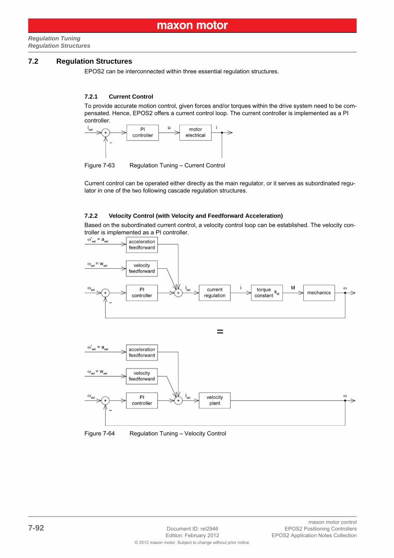
Regulation TuningRegulation Structures
© 2012 maxon motor. Subject to change without prior notice.
maxon motor control7-92 Document ID: rel2946 EPOS2 Positioning Controllers
Edition: February 2012 EPOS2 Application Notes Collection
7.2 Regulation StructuresEPOS2 can be interconnected within three essential regulation structures.
7.2.1 Current Control
To provide accurate motion control, given forces and/or torques within the drive system need to be com-pensated. Hence, EPOS2 offers a current control loop. The current controller is implemented as a PI controller.
Figure 7-63 Regulation Tuning – Current Control
Current control can be operated either directly as the main regulator, or it serves as subordinated regu-lator in one of the two following cascade regulation structures.
7.2.2 Velocity Control (with Velocity and Feedforward Acceleration)
Based on the subordinated current control, a velocity control loop can be established. The velocity con-troller is implemented as a PI controller.
Figure 7-64 Regulation Tuning – Velocity Control

Regulation TuningWorking Principle
© 2012 maxon motor. Subject to change without prior notice.
maxon motor controlEPOS2 Positioning Controllers Document ID: rel2946 7-93EPOS2 Application Notes Collection Edition: February 2012
7.2.3 Position Control (with Velocity and Feedforward Acceleration)
Based on the subordinated current control, a position control loop can be established. The position con-troller is implemented as a PID controller.
Figure 7-65 Regulation Tuning – Position Control
To improve the reference action of the motion system, position control is supplemented by feedforward control. Velocity feedforward compensates for speed-proportional friction, whereas known inertia can be taken into account by acceleration feedforward.
7.3 Working Principle«Regulation Tuning» is based on three features:
1) Identification and modelling of the plant.
2) Mapping model parameters of the plant to derivate controller parameters (PI, PID, feedforward).
3) Verification of the resulting regulation structure.
7.3.1 Identification and Modelling
For identification, the plant is activated by a two-point element – positive and negative current of varying amplitudes, which are based on motor parameters – until a stable oscillation of a fixed amplitude is achieved. This experiment is repeated at a different frequency. The characteristics of the oscillations represent substantial properties of the plant.
Hence, the modeling parameters of a simple mathematical model of the plant can be calculated.
7.3.2 Mapping
Now, the model parameters serve for calculation of controller parameters (PI or PID, respectively) and of feedforward velocity and acceleration parameters.
The validity range of the regulation parameters is characterized, among other aspects, by the regulation bandwidth which is determined as well.
7.3.3 Verification
To achieve proper operation with the gained motion control parameters, the system reaction is verified with a motion profile corresponding to the calculated bandwidth.

Regulation TuningRegulation Tuning Wizard
© 2012 maxon motor. Subject to change without prior notice.
maxon motor control7-94 Document ID: rel2946 EPOS2 Positioning Controllers
Edition: February 2012 EPOS2 Application Notes Collection
7.4 Regulation Tuning Wizard«Regulation Tuning» is a procedure for automated parameterization of the three above mentioned motion controller types (current, velocity and positioning regulation) including position control’s feedfor-ward parameters.
For successful Regulation Tuning, correct setup of system parameters in Startup Wizard is essential. Particularly important are…
• Motor data,
• Encoder data, and
• Communication with the PC.
Initiating the “Regulation Tuning Wizard”
1) Complete standard system configuration (Startup Wizard) in «EPOS Studio».
2) Select ¤Wizards¤ and select ¤Regulation Tuning¤.
Figure 7-66 Regulation Tuning Wizard
3) Select one of the two modes (for details “Tuning Modes” on page 7-95):
– ¤Auto Tuning¤
– ¤Expert Tuning¤.
Figure 7-67 Regulation Tuning Mode Selection

Regulation TuningTuning Modes
© 2012 maxon motor. Subject to change without prior notice.
maxon motor controlEPOS2 Positioning Controllers Document ID: rel2946 7-95EPOS2 Application Notes Collection Edition: February 2012
7.5 Tuning Modes
7.5.1 Auto Tuning
Auto Tuning is the Regulation Tuning’s “very-easy-to-use option”. The only thing needed to accomplish automated tuning is to push the start button. A message will inform you that the system will move during the subsequent procedure. Upon confirming the message, Auto Tuning will commence. All required set-tings are already implemented, so Auto Tuning can parameterize the motion system for most common load cases without further help.
Under certain conditions (strong motor cogging torque, unbalanced friction, low position sensor resolu-tion, etc.) however, or to cover particular requirements (wear, noise or energy optimized operation), Expert Tuning may be used.
7.5.2 Expert Tuning
Expert Tuning offers additional self-describing options for optimum regulation behavior. The following example illustrates tuning using Position Control. Handling of Current Control or Velocity Control how-ever are similar.
Expert Tuning’s user interface is divided in four sections:
a) Cascade
b) Identification
c) Parameterization
d) Verification:
Cascade
Provides information on the selected cascade structure.
Figure 7-68 Expert Tuning – Cascade
The view is split into two panes; “Main Regulation” and “Base Regulation” (or subordinated regulation). Their respective status is displayed in colored bars:
• Red: Undimensioned – the controller is not yet parameterized.
• Green: Dimensioned – the controller is already parameterized.
• Grey: Manually Dimensioned – the control parameters are being set manually (“Manual Tun-ing” on page 7-97).
Click ¤Show Parameters¤ to view/alter the currently set values.
Velocity control can be viewed and adjusted (in “Main Regulation” window), even if the position was originally defined to be the main controlled variable. However, in order to avoid inconsistencies with the position main regulations, current control cannot be changed. If velocity control’s current regulation needs to be optimized, velocity must be defined as Main Regulation variable.
Now, Regulation Tuning is being executed in three steps:

Regulation TuningTuning Modes
© 2012 maxon motor. Subject to change without prior notice.
maxon motor control7-96 Document ID: rel2946 EPOS2 Positioning Controllers
Edition: February 2012 EPOS2 Application Notes Collection
Identification
Figure 7-69 Expert Tuning – Identification
Tick ¤Identify¤ if identification of a new plant is necessary (e.g. if the plant properties have changed). In this case, the status of the corresponding controller, as well as all controllers of higher regulation hierar-chy, will change to “Undimensioned” (red).
By adjusting the identification amplitude, nonlinear properties (e.g. Coulomb Friction) can be simulated appropriately and can be considered in the plant model by means of harmonic linearization. However, presetting already offers a good basis for plant identification for most applications.
Parameterization
Figure 7-70 Expert Tuning – Parameterization
The calculated controller parameters can be modified to match given requirements by means of sliders:
• “Soft” means: slow regulation behavior, but well dampened.
• “Hard” means: quick regulation behavior, but less dampened.
Tick ¤Respect Cogging Torque¤ to achieve a hard, nevertheless well dampened motion regulation, which brings particular advantages for motors with high cogging torque. In case of unbalanced friction, the regulation behavior can be improved with this adjustment as well.
Verification
The verification of the resulting control system – including feedforward – permits examination of the overall performance. The verification can either take place with a movement profile (which takes band-width of the position regulation into account), or a step response. As interesting feature; in addition to the position, the corresponding current is recorded, too.
To zoom the recorded diagrams, crop the “area of interest” and click right.
Figure 7-71 Expert Tuning – Verification
The parameters “Position Step”, “Velocity”, “Acceleration” and “Deceleration” are computed automati-cally. They can be adjusted only if the positioning controller is in state “Manually Dimensioned” (grey).

Regulation TuningTuning Modes
© 2012 maxon motor. Subject to change without prior notice.
maxon motor controlEPOS2 Positioning Controllers Document ID: rel2946 7-97EPOS2 Application Notes Collection Edition: February 2012
The parameter “Max. Recording Time” limits the time interval for data acquisition. This can be useful, if details concerning the beginning of the movement profile are of interest.
¤Start¤ launches Expert Tuning. ¤Finish¤ will save the obtained feedback and feedforward parameters in the EPOS2 and make them valid for all operation modes. ¤Cancel¤ will reject the results and returns to the starting situation.
7.5.3 Manual Tuning
In certain conditions, you might wish to change control parameters manually to see how the system reacts without performing automated system identification and modelling.
Also, the manual mode can be used…
• for fine tuning and optimization in very demanding applications, or
• if the outcome of Auto Tuning/Expert Tuning is not satisfactory.
Initiate Manual Tuning by selecting ¤Manually Dimensioned¤ in ¤Show Parameter¤ dialog (“Cascade” on page 7-95). As a result, the status will switch to “Manually Dimensioned” (grey), thus neither auto-mated identification nor parameterization will be carried out. In addition, you can define the motion pro-file (“Verification” on page 7-96).
After ticking ¤Identify¤, or if you make any changes (“Parameterization” on page 7-96), Manual Tun-ing is terminated showing status “Undimensioned” (red).

Regulation TuningTuning Modes
© 2012 maxon motor. Subject to change without prior notice.
maxon motor control7-98 Document ID: rel2946 EPOS2 Positioning Controllers
Edition: February 2012 EPOS2 Application Notes Collection
• • p a g e i n t e n t i o n a l l y l e f t b l a n k • •

Device ProgrammingIn Brief
© 2012 maxon motor. Subject to change without prior notice.
maxon motor controlEPOS2 Positioning Controllers Document ID: rel2946 8-99EPOS2 Application Notes Collection Edition: February 2012
8 Device Programming
8.1 In BriefA wide variety of operating modes permit flexible configuration of drive and automation systems by using positioning, speed and current regulation. The built-in CANopen interface allows networking to multiple axes drives as well as online commanding by CAN bus master units.
8.1.1 Objective
The present Application Note explains typical commanding sequences for different operating modes. The explanations are based on writing/reading commands to access the Object Dictionary. For detailed information on the objects itself separate document «EPOS2 Firmware Specification» (subsequently referred to as “FwSpec”). For detailed information on the command structure «EPOS Studio» (com-mand analyzer).
Contents
8.2 First Step . . . . . . . . . . . . . . . . . . . . . . . . . . . . . . . . . . . . . . . . . . . . . . . . . . . . . . . . . . . . . . . . . . 8-100
8.3 Homing Mode . . . . . . . . . . . . . . . . . . . . . . . . . . . . . . . . . . . . . . . . . . . . . . . . . . . . . . . . . . . . . . . 8-101
8.4 Profile Position Mode . . . . . . . . . . . . . . . . . . . . . . . . . . . . . . . . . . . . . . . . . . . . . . . . . . . . . . . . . 8-103
8.5 Profile Velocity Mode . . . . . . . . . . . . . . . . . . . . . . . . . . . . . . . . . . . . . . . . . . . . . . . . . . . . . . . . . 8-105
8.6 Interpolated Position Mode (PVT). . . . . . . . . . . . . . . . . . . . . . . . . . . . . . . . . . . . . . . . . . . . . . . . 8-106
8.7 Position Mode . . . . . . . . . . . . . . . . . . . . . . . . . . . . . . . . . . . . . . . . . . . . . . . . . . . . . . . . . . . . . . . 8-106
8.8 Velocity Mode . . . . . . . . . . . . . . . . . . . . . . . . . . . . . . . . . . . . . . . . . . . . . . . . . . . . . . . . . . . . . . . 8-108
8.9 Current Mode . . . . . . . . . . . . . . . . . . . . . . . . . . . . . . . . . . . . . . . . . . . . . . . . . . . . . . . . . . . . . . . 8-110
8.10 State Machine. . . . . . . . . . . . . . . . . . . . . . . . . . . . . . . . . . . . . . . . . . . . . . . . . . . . . . . . . . . . . . 8-112
8.11 Motion Info . . . . . . . . . . . . . . . . . . . . . . . . . . . . . . . . . . . . . . . . . . . . . . . . . . . . . . . . . . . . . . . . 8-113
8.12 Utilities . . . . . . . . . . . . . . . . . . . . . . . . . . . . . . . . . . . . . . . . . . . . . . . . . . . . . . . . . . . . . . . . . . . 8-114
8.1.2 Scope
Table 8-88 Device Programming – covered Hardware and required Documents
Hardware Order # Firmware Version Reference
EPOS2 2110h Firmware Specification
EPOS2 70/10 375711 2120h or higher
EPOS2 50/5 347717 2110h or higher
EPOS2 Module 36/2 360665 2110h or higher
EPOS2 24/5 367676 2110h or higher
EPOS2 24/2380264390003390438
2121h or higher

Device ProgrammingFirst Step
© 2012 maxon motor. Subject to change without prior notice.
maxon motor control8-100 Document ID: rel2946 EPOS2 Positioning Controllers
Edition: February 2012 EPOS2 Application Notes Collection
8.1.3 Tools
Table 8-89 Device Programming – recommended Tools
8.2 First StepBefore the motor will be activated, motor parameters, position sensor parameters and regulation gains must be set. For detailed description FwSpec.
NoteFor detailed information on the command structure «EPOS Studio» (command analyzer).
Table 8-90 Device Programming – First Step
Tools Description
Software «EPOS Studio» Version 1.41 or higher
Object Name Object User Value [Default Value]
CAN Bitrate RS232 Baudrate
0x2001-000x2002-00
User-specific [0]User-specific [3]
Motor TypeContinuous Current LimitPole Pair NumberThermal Time Constant Winding
0x6402-000x6410-010x6410-030x6410-05
Motor-specific [10]Motor-specific [5000]Motor-specific [1]Motor-specific [40]
Encoder Pulse NumberPosition Sensor Type
0x2210-010x2210-02
Sensor-specific [500]Sensor-specific [1]
Current Regulator P-GainCurrent Regulator I-Gain
0x60F6-010x60F6-02
Motor-specific. Determine optimal parameter using “Regulation Tuning” in «EPOS Studio».
Speed Regulator P-GainSpeed Regulator I-Gain
0x60F9-010x60F9-02
Motor-specific. Determine optimal parameter using “Regulation Tuning” in «EPOS Studio».
Position Regulator P-GainPosition Regulator I-GainPosition Regulator D-Gain
0x60FB-010x60FB-020x60FB-03
Motor-specific. Determine optimal parameter using “Regulation Tuning” in «EPOS Studio».

Device ProgrammingHoming Mode
© 2012 maxon motor. Subject to change without prior notice.
maxon motor controlEPOS2 Positioning Controllers Document ID: rel2946 8-101EPOS2 Application Notes Collection Edition: February 2012
8.3 Homing Mode
8.3.1 Start Homing
The axis references to an absolute position using the selected homing method.
Table 8-91 Device Programming – Homing Mode (Start)
8.3.2 Read Status
Table 8-92 Device Programming – Homing Mode (Read)
Object Name Object User Value [Default Value]
Modes of Operation 0x6060-00 0x06 (Homing Mode)
Max. Following ErrorHome OffsetMax. Profile VelocityQuick Stop DecelerationSpeed for Switch SearchSpeed for Zero SearchHoming AccelerationCurrent Threshold Homing ModeHome Position
0x6065-000x607C-000x607F-000x6085-000x6099-010x6099-020x609A-000x2080-000x2081-00
User-specific [2000 qc]User-specific [0 qc]Motor-specific [25000 rpm]User-specific [10000 rpm/s]User-specific [100 rpm]User-specific [10 rpm]User-specific [1000 rpm/s]User-specific [500 mA]User-specific [0 qc]
Homing Method 0x6098-00 Select Homing Method (FwSpec)
Controlword (Shutdown)Controlword (Switch-on)
0x6040-000x6040-00
0x00060x000F
Controlword (Start homing mode) 0x6040-00 0x001F
Object Name Object User Value [Default Value]
Statusword (Target reached / Homing attained)
0x6041-00 Home position is reached if bit 10 / bit 12 is set to 1.

Device ProgrammingHoming Mode
© 2012 maxon motor. Subject to change without prior notice.
maxon motor control8-102 Document ID: rel2946 EPOS2 Positioning Controllers
Edition: February 2012 EPOS2 Application Notes Collection
8.3.3 Stop Positioning
Table 8-93 Device Programming – Homing Mode (Stop)
Object Name Object User Value [Default Value]
Controlword (Switch-on) orControlword (Halt homing) orControlword (Quick stop)
0x6040-00
0x6040-00
0x6040-00
0x000F
0x011F
0x000B

Device ProgrammingProfile Position Mode
© 2012 maxon motor. Subject to change without prior notice.
maxon motor controlEPOS2 Positioning Controllers Document ID: rel2946 8-103EPOS2 Application Notes Collection Edition: February 2012
8.4 Profile Position Mode
8.4.1 Set Position
The axis moves to an absolute or relative position using a motion profile.
Table 8-94 Device Programming – Profile Position Mode (Set)
8.4.2 Read Status
Table 8-95 Device Programming – Profile Position Mode (Read)
Object Name Object User Value [Default Value]
Modes of Operation 0x6060-00 0x01 (Profile Position Mode)
Max. Following ErrorMin. Position LimitMax. Position LimitMax. Profile VelocityProfile VelocityProfile AccelerationProfile DecelerationQuick Stop DecelerationMotion Profile Type
0x6065-000x607D-010x607D-020x607F-000x6081-000x6083-000x6084-000x6085-000x6086-00
User-specific [2000 qc]User-specific [-2147483648 qc]User-specific [2147483647 qc]Motor-specific [25000 rpm]Desired Velocity [1000 rpm]User-specific [10000 rpm/s]User-specific [10000 rpm/s]User-specific [10000 rpm/s]User-specific [0]
Controlword (Shutdown)Controlword (Switch-on)
0x6040-000x6040-00
0x00060x000F
Target Position 0x607A-00 Desired Position [qc]
Controlword (absolute pos.) orControlword (absolute pos., start immediately) orControlword (relative pos., start immediately) orControlword (relative positioning)
0x6040-00
0x6040-00
0x6040-00
0x6040-00
0x001F
0x003F
0x007F
0x005F
Object Name Object User Value [Default Value]
Statusword (Target reached) 0x6041-00 The axis is at target position if bit 10 is set.

Device ProgrammingProfile Position Mode
© 2012 maxon motor. Subject to change without prior notice.
maxon motor control8-104 Document ID: rel2946 EPOS2 Positioning Controllers
Edition: February 2012 EPOS2 Application Notes Collection
8.4.3 Stop Positioning
Table 8-96 Device Programming – Profile Position Mode (Stop)
Object Name Object User Value [Default Value]
Controlword (Stop positioning) orControlword (Quick stop)
0x6040-00
0x6040-00
0x010F
0x000B

Device ProgrammingProfile Velocity Mode
© 2012 maxon motor. Subject to change without prior notice.
maxon motor controlEPOS2 Positioning Controllers Document ID: rel2946 8-105EPOS2 Application Notes Collection Edition: February 2012
8.5 Profile Velocity Mode
8.5.1 Start Velocity
Motor shaft rotates with a certain speed with velocity profile.
Table 8-97 Device Programming – Profile Velocity Mode (Start)
8.5.2 Read Status
Table 8-98 Device Programming – Profile Velocity Mode (Read)
8.5.3 Stop Velocity
Table 8-99 Device Programming – Profile Velocity Mode (Stop)
Object Name Object User Value [Default Value]
Modes of Operation 0x6060-00 0x03 (Profile Velocity Mode)
Max. Profile VelocityProfile AccelerationProfile DecelerationQuick Stop DecelerationMotion Profile Type
0x607F-000x6083-000x6084-000x6085-000x6086-00
Motor-specific [25000 rpm]User-specific [10000 rpm/s]User-specific [10000 rpm/s]User-specific [10000 rpm/s]User-specific [0]
Controlword (Shutdown)Controlword (Switch-on)
0x6040-000x6040-00
0x00060x000F
Target Velocity 0x60FF-00 Velocity for movement [rpm]
Controlword 0x6040-00 0x000F
Object Name Object User Value [Default Value]
Statusword (Target velocity reached)
0x6041-00 Target velocity is reached if bit 10 is set.
Object Name Object User Value [Default Value]
Controlword (Halt Profile Velocity Mode) orControlword (Quick stop)
0x6040-00
0x6040-00
0x010F
0x000B

Device ProgrammingInterpolated Position Mode (PVT)
© 2012 maxon motor. Subject to change without prior notice.
maxon motor control8-106 Document ID: rel2946 EPOS2 Positioning Controllers
Edition: February 2012 EPOS2 Application Notes Collection
8.6 Interpolated Position Mode (PVT)For detailed information chapter “6 Interpolated Position Mode” on page 6-71.
8.7 Position Mode
8.7.1 Set Position
The axis moves to the new absolute position with maximum acceleration and maximum velocity without particular trajectory. If the difference between actual and new position is greater than “Max Following Error”, an emergency procedure will be launched.
Table 8-100 Device Programming – Position Mode (Set)
8.7.2 Stop Positioning
Table 8-101 Device Programming – Position Mode (Stop)
Object Name Object User Value [Default Value]
Modes of Operation 0x6060-00 0xFF (Position Mode)
Max. Following ErrorMin. Position LimitMax. Position LimitMax. Profile VelocityMax. Acceleration
0x6065-000x607D-010x607D-020x607F-000x60C5-00
User-specific [2000 qc]User-specific [-2147483648 qc]User-specific [2147483647 qc]Motor-specificUser-specific [4294967295]
Controlword (Shutdown)Controlword (Switch-on)
0x6040-000x6040-00
0x00060x000F
Position Mode Setting Value 0x2062-00 New Position [qc]
Object Name Object User Value [Default Value]
Controlword (Quick stop) 0x6040-00 0x000B

Device ProgrammingPosition Mode
© 2012 maxon motor. Subject to change without prior notice.
maxon motor controlEPOS2 Positioning Controllers Document ID: rel2946 8-107EPOS2 Application Notes Collection Edition: February 2012
8.7.3 Set Position with analog Setpoint
For details FwSpec, chapter “Position Mode”.
Table 8-102 Device Programming – Position Mode (Set, analog)
8.7.4 Stop Positioning from analog Setpoint
Table 8-103 Device Programming – Position Mode (Stop, analog)
Object Name Object User Value [Default Value]
Modes of Operation 0x6060-00 0xFF (Position Mode)
Max. Following ErrorMin. Position LimitMax. Position LimitMax. Profile VelocityMax. Acceleration
Configuration of Analog Input xAnalog Position Setpoint ScalingAnalog Position Setpoint Offset
0x6065-000x607D-010x607D-020x607F-000x60C5-00
0x207B-0x0x2303-010x2303-02
User-specific [2000 qc]User-specific [-2147483648 qc]User-specific [2147483647 qc]Motor-specificUser-specific [4294967295]
0x02User-specific [0]User-specific [0]
Controlword (Shutdown)Controlword (Switch-on)
0x6040-000x6040-00
0x00060x000F
Analog Input Functionalities Execution Mask
0x207D-00 0x02
Position Mode Setting ValueAnalog Position Setpoint
0x2062-000x2303-04
New Position [qc]Calculated value
Object Name Object User Value [Default Value]
Controlword (Quick stop) 0x6040-00 0x000B

Device ProgrammingVelocity Mode
© 2012 maxon motor. Subject to change without prior notice.
maxon motor control8-108 Document ID: rel2946 EPOS2 Positioning Controllers
Edition: February 2012 EPOS2 Application Notes Collection
8.8 Velocity Mode
8.8.1 Set Velocity
Motor shaft runs with a certain speed with maximum acceleration.
Table 8-104 Device Programming – Velocity Mode (Set)
8.8.2 Stop Velocity
Table 8-105 Device Programming – Velocity Mode (Stop)
Object Name Object User Value [Default Value]
Modes of Operation 0x6060-00 0xFE (Velocity Mode)
Max. Profile VelocityMax. Acceleration
0x607F-000x60C5-00
Motor-specificUser-specific [4294967295]
Controlword (Shutdown)Controlword (Switch-on)
0x6040-000x6040-00
0x00060x000F
Velocity Mode Setting Value 0x206B-00 Velocity for movement [rpm]
Object Name Object User Value [Default Value]
Velocity Mode Setting Value orControlword (Quick stop)
0x206B-00
0x6040-00
0x00000000
0x000B

Device ProgrammingVelocity Mode
© 2012 maxon motor. Subject to change without prior notice.
maxon motor controlEPOS2 Positioning Controllers Document ID: rel2946 8-109EPOS2 Application Notes Collection Edition: February 2012
8.8.3 Set Velocity with analog Setpoint
For details FwSpec, chapter “Velocity Mode”.
Table 8-106 Device Programming – Velocity Mode (Set, analog)
8.8.4 Stop Velocity from analog Setpoint
Table 8-107 Device Programming – Velocity Mode (Stop, analog)
Object Name Object User Value [Default Value]
Modes of Operation 0x6060-00 0xFF (Position Mode)
Max. Profile VelocityMax. Acceleration
Configuration of Analog Input xAnalog Velocity Setpoint ScalingAnalog Velocity Setpoint Offset
0x607F-000x60C5-00
0x207B-0x0x2302-010x2302-02
Motor-specificUser-specific [4294967295]
0x01User-specific [0]User-specific [0]
Controlword (Shutdown)Controlword (Switch-on)
0x6040-000x6040-00
0x00060x000F
Analog Input Functionalities Execution Mask
0x207D-00 0x01
Velocity Mode Setting ValueAnalog Position Setpoint
0x2062-000x2303-04
New Position [qc]Calculated value
Object Name Object User Value [Default Value]
Controlword (Quick stop) 0x6040-00 0x000B

Device ProgrammingCurrent Mode
© 2012 maxon motor. Subject to change without prior notice.
maxon motor control8-110 Document ID: rel2946 EPOS2 Positioning Controllers
Edition: February 2012 EPOS2 Application Notes Collection
8.9 Current Mode
8.9.1 Set Current
This command applies a certain current at the motor winding.
Table 8-108 Device Programming – Current Mode (Set)
8.9.2 Stop Motion
Table 8-109 Device Programming – Current Mode (Stop)
Object Name Object User Value [Default Value]
Modes of Operation 0x6060-00 0xFD (Current Mode)
Continuous Current LimitMax. Speed in Current ModeThermal Time Constant Winding
0x6410-010x6410-040x6410-05
Motor-specific (catalog for motor data)
Controlword (Shutdown)Controlword (Switch-on)
0x6040-000x6040-00
0x00060x000F
Current Mode Setting Value 0x2030-00 User-specific current [mA]
Object Name Object User Value [Default Value]
Current Mode Setting Value orControlword (Quick stop)
0x2030-00
0x6040-00
0x0000
0x0002

Device ProgrammingCurrent Mode
© 2012 maxon motor. Subject to change without prior notice.
maxon motor controlEPOS2 Positioning Controllers Document ID: rel2946 8-111EPOS2 Application Notes Collection Edition: February 2012
8.9.3 Set Current with analog Setpoint
For details FwSpec, chapter “Current Mode”.
Table 8-110 Device Programming – Current Mode (Set, analog)
8.9.4 Stop Motion from analog Setpoint
Table 8-111 Device Programming – Current Mode (Stop, analog)
Object Name Object User Value [Default Value]
Modes of Operation 0x6060-00 0xFF (Position Mode)
Continuous Current LimitMax. Speed in Current ModeThermal Time Constant Winding
Configuration of Analog Input xAnalog Current Setpoint ScalingAnalog Current Setpoint Offset
0x6410-010x6410-040x6410-05
0x207B-0x0x2301-010x2301-02
Motor-specific for all parameters (catalog for motor data)
0x00User-specific [0]User-specific [0]
Controlword (Shutdown)Controlword (Switch-on)
0x6040-000x6040-00
0x00060x000F
Analog Input Functionalities Execution Mask
0x207D-00 0x00
Current Mode Setting ValueAnalog Current Setpoint
0x2061-000x2301-04
New Position [qc]Calculated value
Object Name Object User Value [Default Value]
Controlword (Quick stop) 0x6040-00 0x0002

Device ProgrammingState Machine
© 2012 maxon motor. Subject to change without prior notice.
maxon motor control8-112 Document ID: rel2946 EPOS2 Positioning Controllers
Edition: February 2012 EPOS2 Application Notes Collection
8.10 State Machine
8.10.1 Clear Fault
Resetting “Fault” condition sends the Controlword with value 0x0080.
Table 8-112 Device Programming – State Machine (Clear Fault)
8.10.2 Send NMT Service
Table 8-113 Device Programming – State Machine (Send NMT Service)
Object Name Object User Value [Default Value]
Controlword (Fault Reset) 0x6040-00 0x0080
Object Name Object User Value [Default Value]
Node ID (Unique Node ID or 0 for all nodes)
Command specifier: 0x010x020x800x810x82
Start Remote NodeStop Remote NodeEnter Pre-OperationalReset NodeReset Communication

Device ProgrammingMotion Info
© 2012 maxon motor. Subject to change without prior notice.
maxon motor controlEPOS2 Positioning Controllers Document ID: rel2946 8-113EPOS2 Application Notes Collection Edition: February 2012
8.11 Motion Info
8.11.1 Get Movement State
Table 8-114 Device Programming – Motion Info (Get Movement State)
8.11.2 Read Position
Table 8-115 Device Programming – Motion Info (Read Position)
8.11.3 Read Velocity
Table 8-116 Device Programming – Motion Info (Read Velocity)
8.11.4 Read Current
Table 8-117 Device Programming – Motion Info (Read Current)
Object Name Object User Value [Default Value]
Read Statusword 0x6041-00Bit 10 tells states that target is reached. For details FwSpec.
Object Name Object User Value [Default Value]
Read Position 0x6064-00 Position [qc]
Object Name Object User Value [Default Value]
Read Velocity 0x2028-00 Velocity [rpm]
Object Name Object User Value [Default Value]
Read Current 0x6078-00 Current [mA]

Device ProgrammingUtilities
© 2012 maxon motor. Subject to change without prior notice.
maxon motor control8-114 Document ID: rel2946 EPOS2 Positioning Controllers
Edition: February 2012 EPOS2 Application Notes Collection
8.12 Utilities
8.12.1 Store all Parameters
Saves all parameters.
Table 8-118 Device Programming – Utilities (Store all Parameters)
8.12.2 Restore all default Parameters
Restores all parameters to factory settings.
Table 8-119 Device Programming – Utilities (Restore all default Parameters)
8.12.3 Restore default PDO COB-ID
Sets all COB-IDs of PDOs to default (Node ID based) value.
Table 8-120 Device Programming – Utilities (Restore default PDO COB-ID)
Object Name Object User Value [Default Value]
Save All Parameters 0x10101-01 0x65766173 “save”
Object Name Object User Value [Default Value]
Restore All Default Parameters 0x1011-01 0x64616F6C “load”
Object Name Object User Value [Default Value]
Restore Default COB-IDs 0x1011-05 0x64616F6C “load”

Controller ArchitectureIn Brief
© 2012 maxon motor. Subject to change without prior notice.
maxon motor controlEPOS2 Positioning Controllers Document ID: rel2946 9-115EPOS2 Application Notes Collection Edition: February 2012
9 Controller Architecture
9.1 In BriefA wide variety of operating modes permit flexible configuration of drive and automation systems by using positioning, speed and current regulation. The built-in CANopen interface allows networking to multiple axes drives as well as online commanding by CAN bus master units.
In addition to the standard EPOS2 PID position control, also feedforward compensation is available. The feedforward compensation provides faster setpoint following in applications with higher load inertia and accelerations and/or in applications with considerable speed-dependent load (as with friction-afflicted drives). With some EPOS2 Positioning Controllers, dual loop regulation is available.
9.1.1 Objective
The present Application Note explains the EPOS2 controller architecture. Furthermore explained will be mapping of internal controller parameters to controller parameters in SI units, and vice versa.
In addition to PID position regulation, the functionalities of built-in acceleration and velocity feedforward are described. Their advantages, compared to simple PID control are shown using two “in practice examples”.
Contents
9.2 Overview. . . . . . . . . . . . . . . . . . . . . . . . . . . . . . . . . . . . . . . . . . . . . . . . . . . . . . . . . . . . . . . . . . . 9-116
9.3 Regulation Methods . . . . . . . . . . . . . . . . . . . . . . . . . . . . . . . . . . . . . . . . . . . . . . . . . . . . . . . . . . 9-117
9.4 Regulation Tuning. . . . . . . . . . . . . . . . . . . . . . . . . . . . . . . . . . . . . . . . . . . . . . . . . . . . . . . . . . . . 9-120
9.5 Dual Loop Regulation . . . . . . . . . . . . . . . . . . . . . . . . . . . . . . . . . . . . . . . . . . . . . . . . . . . . . . . . . 9-121
9.6 Application Examples . . . . . . . . . . . . . . . . . . . . . . . . . . . . . . . . . . . . . . . . . . . . . . . . . . . . . . . . . 9-124
9.7 Conclusion . . . . . . . . . . . . . . . . . . . . . . . . . . . . . . . . . . . . . . . . . . . . . . . . . . . . . . . . . . . . . . . . . 9-138
9.1.2 Scope
Table 9-121 Controller Architecture – covered Hardware and required Documents
9.1.3 Tools
Table 9-122 Controller Architecture – recommended Tools
Hardware Order # Firmware Version Reference
EPOS2 2121h Firmware Specification
EPOS2 70/10 375711 2120h or higher
EPOS2 50/5 347717 2110h or higher
EPOS2 Module 36/2 360665 2110h or higher
EPOS2 24/5 367676 2110h or higher
EPOS2 24/2380264390003390438
2121h or higher
Tools Description
Software «EPOS Studio» Version 1.43 or higher

Controller ArchitectureOverview
© 2012 maxon motor. Subject to change without prior notice.
maxon motor control9-116 Document ID: rel2946 EPOS2 Positioning Controllers
Edition: February 2012 EPOS2 Application Notes Collection
9.2 OverviewThe EPOS2 controller architecture contains three built-in control loops.
• Current regulation is used in all modes.
• Position and velocity controllers are only used in position-based, respectively velocity-based modes.
• Current control loop receives as input the position, respectively velocity controller’s output.
Figure 9-72 Controller Architecture
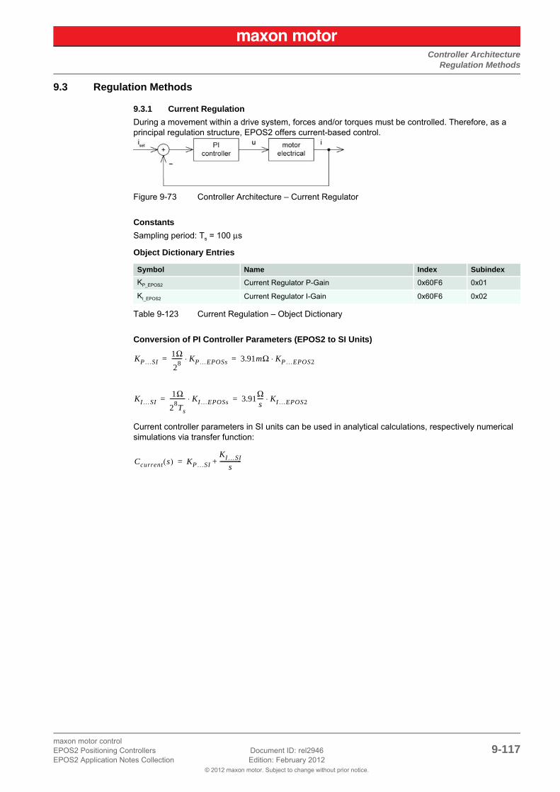
Controller ArchitectureRegulation Methods
© 2012 maxon motor. Subject to change without prior notice.
maxon motor controlEPOS2 Positioning Controllers Document ID: rel2946 9-117EPOS2 Application Notes Collection Edition: February 2012
9.3 Regulation Methods
9.3.1 Current Regulation
During a movement within a drive system, forces and/or torques must be controlled. Therefore, as a principal regulation structure, EPOS2 offers current-based control.
Figure 9-73 Controller Architecture – Current Regulator
Constants
Sampling period: Ts = 100 μs
Object Dictionary Entries
Table 9-123 Current Regulation – Object Dictionary
Conversion of PI Controller Parameters (EPOS2 to SI Units)
Current controller parameters in SI units can be used in analytical calculations, respectively numerical simulations via transfer function:
Symbol Name Index Subindex
KP_EPOS2 Current Regulator P-Gain 0x60F6 0x01
KI_EPOS2 Current Regulator I-Gain 0x60F6 0x02
KP…SI1Ω
28------- KP…EPOSs⋅ 3.91mΩ KP…EPOS2⋅= =
KI…SI1Ω
28Ts
----------- KI…EPOSs⋅ 3.91Ωs---- KI…EPOS2⋅= =
Ccurrent s( ) KP…SI
KI…SI
s---------------+=

Controller ArchitectureRegulation Methods
© 2012 maxon motor. Subject to change without prior notice.
maxon motor control9-118 Document ID: rel2946 EPOS2 Positioning Controllers
Edition: February 2012 EPOS2 Application Notes Collection
9.3.2 Velocity Regulation (with Feedforward)
Based on the subordinated current control, EPOS2 also offers velocity regulation.
Figure 9-74 Controller Architecture – Velocity Regulator
Constants
Sampling period: Ts = 1 ms
Object Dictionary Entries
Table 9-124 Velocity Regulation – Object Dictionary
Conversion of PI Controller Parameters (EPOS2 to SI Units)
Velocity controller parameters in SI units can be used in analytical calculations, respectively numerical simulations via transfer function:
Conversion of Feedforward Parameters (EPOS2 to SI Units)
Symbol Name Index Subindex
KP_EPOS2 Speed Regulator P-Gain 0x60F9 0x01
KI_EPOS2 Speed Regulator I-Gain 0x60F9 0x02
Kω_EPOS2 Velocity Feedforward Factor in Speed Regulator 0x60F9 0x04
Kα_EPOS2Acceleration Feedforward Factor in Speed Regulator
0x60F9 0x05
Velocity feedforward:
Acceleration feedforward:
KP…SI 20 μArad( ) s⁄
-------------------- KP…EPOS2⋅=
KI…SI 5 mA( ) s⁄rad( ) s⁄
-------------------- KI…EPOS2⋅=
Cvelocity s( ) KP…SI
KI…SI
s---------------+=
Kω…SI 1 μArad( ) s⁄
-------------------- Kω…EPOS2⋅=
Kα…SI 1 μA
rad( ) s⁄ 2---------------------- Kα…EPOS2⋅=

Controller ArchitectureRegulation Methods
© 2012 maxon motor. Subject to change without prior notice.
maxon motor controlEPOS2 Positioning Controllers Document ID: rel2946 9-119EPOS2 Application Notes Collection Edition: February 2012
9.3.3 Position Regulation (with Feedforward)
Based on the subordinated current control, EPOS2 is able to close a positioning control loop.
Figure 9-75 Controller Architecture – Position Regulator with Feedforward
Constants
Sampling period: Ts = 1 ms
Object Dictionary Entries
Table 9-125 Position Regulation with Feedforward – Object Dictionary
The position controller is implemented as PID controller. To improve the motion system’s setpoint fol-lowing, positioning regulation is supplemented by feedforward control. Thereby, velocity feedforward serves for compensation of speed-proportional friction, whereas acceleration feedforward considers known inertia.
Conversion of PI Controller Parameters (EPOS2 to SI Units)
Position controller parameters in SI units can be used in analytical calculations, respectively numerical simulations via transfer function:
Symbol Name Index Subindex
KP_EPOS2 Position Regulator P-Gain 0x60FB 0x01
KI_EPOS2 Position Regulator I-Gain 0x60FB 0x02
KD_EPOS2 Position Regulator D-Gain 0x60FB 0x03
Kω_EPOS2 Velocity Feedforward Factor in Position Regulator 0x60FB 0x04
Kα_EPOS2Acceleration Feedforward Factor in Position Regulator
0x60FB 0x05
KP…SI 10 mArad--------- KP…EPOS2⋅=
KI…SI 78 mA( ) s⁄rad
------------------- KI…EPOS2⋅=
KD…SI 80μAsrad---------- KD…EPOS2⋅=
Cposition s( ) KP…SI
KI…SI
s---------------
KD…SIS
1KD…SI
16KP…SI-----------------------s+
-----------------------------------+ +=

Controller ArchitectureRegulation Tuning
© 2012 maxon motor. Subject to change without prior notice.
maxon motor control9-120 Document ID: rel2946 EPOS2 Positioning Controllers
Edition: February 2012 EPOS2 Application Notes Collection
Conversion of Feedforward Parameters (EPOS2 to SI Units)
9.3.4 Operation Modes with Feedforward
Acceleration and velocity feedforward have an effect in «Profile Position Mode», «Profile Velocity Mode» and «Homing Mode». All other operating modes are not influenced.
9.3.4.1 Purpose of Velocity Feedforward
Velocity feedforward provides additional current in cases, where the load increases with speed, such as speed-dependent friction. The load is assumed to increase proportional with speed. The optimal velocity feedforward parameter in SI units is…
Meaning: With given total friction proportional factor “r” relative to the motor shaft, and the motor’s torque constant “kM”, you ought to adjust the velocity feedforward parameter to…
9.3.4.2 Purpose of Acceleration Feedforward
Acceleration feedforward provides additional current in cases of high acceleration and/or high load iner-tias. The optimal acceleration feedforward parameter in SI units is…
Meaning: With given total inertia “J” relative to the motor shaft, and the motor’s torque constant “kM”, you ought to adjust the acceleration feedforward parameter to…
9.4 Regulation Tuningmaxon motor’s «EPOS Studio» features «Regulation Tuning» as powerful wizard allowing to automati-cally tune all controller and feedforward parameters described above for most drive systems within a few minutes. For details chapter “7 Regulation Tuning” on page 7-91.
Velocity feedforward:
Acceleration feedforward:
Kω…SI 1 μArad( ) s⁄
-------------------- Kω…EPOS2⋅=
Kα…SI 1 μA
rad( ) s⁄ 2---------------------- Kα…EPOS2⋅=
Kω…SIr
kM------=
Kω…EPOS2r
kM------ rad( ) s⁄
1μA--------------------⋅ r
kM------ 106
rad( ) s⁄A
-----------------------------⋅= =
Kα…SIJ
kM------=
Kα…EPOS2J
kM------ rad( ) s⁄ 2
1μA----------------------⋅ J
kM------ 106
rad( ) s⁄2
A-------------------------------⋅= =

Controller ArchitectureDual Loop Regulation
© 2012 maxon motor. Subject to change without prior notice.
maxon motor controlEPOS2 Positioning Controllers Document ID: rel2946 9-121EPOS2 Application Notes Collection Edition: February 2012
9.5 Dual Loop Regulation
Available with EPOS2 70/10, EPOS2 50/5 and EPOS2 Module 36/2 only!
In many applications it is common to use gears to increase motor torque, or screw spindles to transform motor rotation into linear movement. The gear itself is made of a lot of different parts, such as, belts, pin-ions, pulleys, spindles, etc.
The associated elasticity and backlash of these parts create an effect of compliance and as well as a delay in the drive chain. Often, the mechanical transmission between motor and load has some back-lash, too, resulting in a certain “delay” being introduced to the plant. This delay influences the regulation stability and may have such big impact that one may be forced to reduce the dynamic behavior or the precision of the drive.
To overcome these limitations and to combine a motor/gear system with a precise and high dynamic regulation, it will be necessary to control the motor movement as well as the load movement. This results in a new control structure called “dual loop”, featuring two individual encoders – one directly mounted to the motor, the another mounted at the gear or linear slide or directly on/near to the load.
Figure 9-76 Dual Loop Architecture
The auxiliary regulation is designed to provide damping and dynamic system behavior while the main regulation generates the desired position precision.
9.5.1 Current Regulation
The dual loop current controller is implemented similar to the current controller in a single loop system. For details chapter “9.3.1 Current Regulation” on page 9-117.

Controller ArchitectureDual Loop Regulation
© 2012 maxon motor. Subject to change without prior notice.
maxon motor control9-122 Document ID: rel2946 EPOS2 Positioning Controllers
Edition: February 2012 EPOS2 Application Notes Collection
9.5.2 Velocity Regulation (with Feedforward)
The design is based on current regulation.
Figure 9-77 Dual Loop Velocity Regulation
In velocity mode, the auxiliary controller appropriately stabilizes the loop; however, the main controller provides the correct speed feedback.
The dual loop velocity controller (that is main controller and auxiliary controller together) is implemented as PI controller.
Conversion parameters
Conversion of PI controller and feedforward parameters in dual loop (EPOS2 to SI units) are identical to that in single loop (chapter “9.3.2 Velocity Regulation (with Feedforward)” on page 9-118).
9.5.3 Position Regulation (with Feedforward)
The design is based on current regulation.
Figure 9-78 Dual Loop Position Regulation
motor speedload speed
motor speedload position
ωM
ωL
ωM
ϕL

Controller ArchitectureDual Loop Regulation
© 2012 maxon motor. Subject to change without prior notice.
maxon motor controlEPOS2 Positioning Controllers Document ID: rel2946 9-123EPOS2 Application Notes Collection Edition: February 2012
In position mode, the auxiliary controller is designed to stabilize the loop, whereas the main controller provides the correct position feedback.
The dual loop position controller (that is main controller and auxiliary controller together) is realized as PID controller and features the same sampling period as the dual loop velocity controller.
Conversion parameters
Conversion of PI controller and feedforward parameters in dual loop (EPOS2 to SI units) are identical to that in single loop (chapter “9.3.3 Position Regulation (with Feedforward)” on page 9-119).
9.5.4 Conclusion
The dual loop topology is adequate if the ratio of motor inertia and load inertia is not too large. The drive elements (motor, gear, encoders, load) must be dimensioned correctly.
General Selection Practice
To achieve reliability of the system, follow the scheme below to determine the individual components:
• MotorChose a motor capable to fulfill the load’s requirements for maximum torque, continuous torque, and speed. For detailed information chapter “1.6 Sources for additional Information” on page 1-11, item [ 7 ]).
• GearChose a gear capable to fulfill the load’s torque and speed range. Boundary conditions are maxi-mum motor load, maximum gear load, and the associated speed limits.Another influence that might need consideration is the minimum motor heat dissipation capability. Use the following formula to determine the optimum gear ratio:
• Motor EncoderChose a motor encoder capable to provide sufficient stiffness in the inner loop. A few hundred increments per revolution as the motor encoder’s minimum resolution are recommended.
• Load EncoderChose a load encoder capable to at least deliver the required resolution and accuracy on the load side.
General RuleWith Dual Loop Regulation, the following general restriction applies:
9.5.5 Auto Tuning
The dual loop start up is similar to the start up of the single loop regulation and can be described with the following major steps:
1) Identification and modeling of the plant.
2) Calculation of all controller parameters (current, auxiliary, main, feedforward).
3) Mapping; the calculated controller parameters (main, auxiliary) are mathematically transformed to PI controller parameters (for velocity regulation) or to PID controller parameters (for position regulation).
4) Verification; the system’s dynamic response is measured and displayed using the scope function in «EPOS2 Studio». This allows verification, whether the system behavior is as expected.
load inertiamotor inertia
I JlJm-------=
Jl
Jm
AuxEncoderResolution GearRatio⋅ MainEncoderResolution≤

Controller ArchitectureApplication Examples
© 2012 maxon motor. Subject to change without prior notice.
maxon motor control9-124 Document ID: rel2946 EPOS2 Positioning Controllers
Edition: February 2012 EPOS2 Application Notes Collection
9.6 Application ExamplesPlease find below two “in practice examples” suitable for daily use.
For comparability and validity reasons, the measured simulation results are converted to theunits “mA”, “rpm” and “qc”!
9.6.1 Example 1: System with high Inertia and low Friction
System Components
Table 9-126 Controller Architecture – Example 1: Components
Model of the Plant
The following parameters can be deduced:
Figure 9-79 Example1 – Block Diagram
Item Description Setting
ControllerEPOS2 50/5 (347717)
Motormaxon EC 40 (118896)
No load speed (line 2) n0 = 10’400 rpm
No load current (line 3) I0 = 258 mA
Nominal current (line 6) In = 3.4 A
Resistance phase to phase (line 10) R = 1.25 Ω
Inductance phase to phase (line 11) L = 0.319 mH
Torque constant (line 12) kM = 38.2 mNm/A
Rotor inertia (line 16) Jmotor = 85 gcm2
EncoderHEDL 5540 (110516)
Encoder pulse number 500
Mechanical loadFly wheel
Inertia Jload = 5000 gcm2

Controller ArchitectureApplication Examples
© 2012 maxon motor. Subject to change without prior notice.
maxon motor controlEPOS2 Positioning Controllers Document ID: rel2946 9-125EPOS2 Application Notes Collection Edition: February 2012
Electrical Part
R = 1.25 Ω
L = 0.319 mH
Interface between electrical and mechanical Parts
Mechanical Part
• Input is the voltage at the motor winding.
• Outputs are current, velocity or position.
Regulation Tuning as to the described conditions results in the following controller and feedforward parameters:
Figure 9-80 Example1 – System Parameters, real
For numerical simulation, the conversion results from EPOS2 to SI units are as follows:
Current Controller
kM 38.2mNmA
-------------=
J Jmotor Jload+ 5085gcm2= =
rkMI0
n02πrad
1---------------- 1min
60s-------------⋅
---------------------------------------- 9.86mNm
1089rad2
------------------------ 9.05 μNmrad( ) s⁄
--------------------= = =
KP…EPOS2 434= KP…SI 1.70Ω=
KI…EPOS2 105= KI…SI 4.11kΩs
-------=
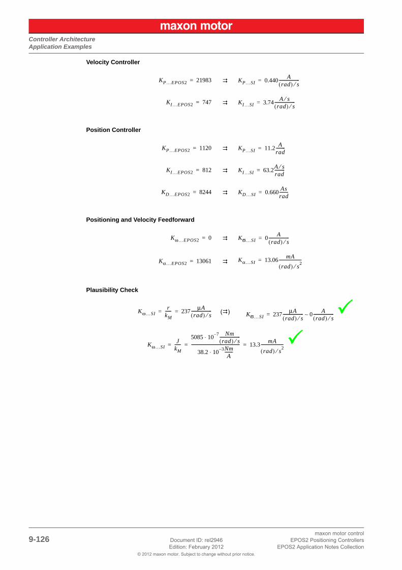
Controller ArchitectureApplication Examples
© 2012 maxon motor. Subject to change without prior notice.
maxon motor control9-126 Document ID: rel2946 EPOS2 Positioning Controllers
Edition: February 2012 EPOS2 Application Notes Collection
Velocity Controller
Position Controller
Positioning and Velocity Feedforward
Plausibility Check
()
KP…EPOS2 21983= KP…SI 0.440 Arad( ) s⁄
--------------------=
KI…EPOS2 747= KI…SI 3.74 A s⁄rad( ) s⁄
--------------------=
KP…EPOS2 1120= KP…SI 11.2 Arad---------=
KI…EPOS2 812= KI…SI 63.2A s⁄rad----------=
KD…EPOS2 8244= KD…SI 0.660 Asrad---------=
Kω…EPOS2 0= Kϖ…SI 0 Arad( ) s⁄
--------------------=
Kα…EPOS2 13061= Kα…SI 13.06 mA
rad( ) s2⁄
----------------------=
Kω…SIr
kM------ 237 μA
rad( ) s⁄--------------------= = Kϖ…SI 237 μA
rad( ) s⁄-------------------- 0 A
rad( ) s⁄--------------------∼=
Kω…SIJ
kM------
5085 10⋅ 7– Nmrad( ) s⁄
--------------------
38.2 10 3–⋅ NmA
-------------------------------------------------------- 13.3 mA
rad( ) s⁄ 2----------------------= = =

Controller ArchitectureApplication Examples
© 2012 maxon motor. Subject to change without prior notice.
maxon motor controlEPOS2 Positioning Controllers Document ID: rel2946 9-127EPOS2 Application Notes Collection Edition: February 2012
Verification of Current Control
The plant is connected to the PI current controller. The controller is parameterized as described above.
Figure 9-81 Example1 – Current Regulation, Block Model
Figure 9-82 Example1 – Current Regulation, simulated
Figure 9-83 Example1 – Current Regulation, measured

Controller ArchitectureApplication Examples
© 2012 maxon motor. Subject to change without prior notice.
maxon motor control9-128 Document ID: rel2946 EPOS2 Positioning Controllers
Edition: February 2012 EPOS2 Application Notes Collection
Verification of Velocity Control
The PI velocity controller is connected to current regulation.
Figure 9-84 Example1 – Velocity Regulation, Block Model
Figure 9-85 Example1 – Velocity Regulation, simulated
Figure 9-86 Example1 – Velocity Regulation, measured

Controller ArchitectureApplication Examples
© 2012 maxon motor. Subject to change without prior notice.
maxon motor controlEPOS2 Positioning Controllers Document ID: rel2946 9-129EPOS2 Application Notes Collection Edition: February 2012
Verification of Position Control with Feedforward
The PID position controller is connected to current regulation.
Figure 9-87 Example1 – Position Control with Feedforward, Block Model
With correct Feedforward
Figure 9-88 Example1 – Position Control with Feedforward, simulated
Figure 9-89 Example1 – Position Control with Feedforward, measured

Controller ArchitectureApplication Examples
© 2012 maxon motor. Subject to change without prior notice.
maxon motor control9-130 Document ID: rel2946 EPOS2 Positioning Controllers
Edition: February 2012 EPOS2 Application Notes Collection
Without Feedforward
Figure 9-90 Example1 – Position Control without Feedforward, simulated
Figure 9-91 Example1 – Position Control without Feedforward, measured

Controller ArchitectureApplication Examples
© 2012 maxon motor. Subject to change without prior notice.
maxon motor controlEPOS2 Positioning Controllers Document ID: rel2946 9-131EPOS2 Application Notes Collection Edition: February 2012
With incorrect Feedforward (acceleration Feedforward parameter doubled)
Figure 9-92 Example1 – Position Control with incorrect Feedforward, simulated
Figure 9-93 Example1 – Position Control with incorrect Feedforward, measured

Controller ArchitectureApplication Examples
© 2012 maxon motor. Subject to change without prior notice.
maxon motor control9-132 Document ID: rel2946 EPOS2 Positioning Controllers
Edition: February 2012 EPOS2 Application Notes Collection
9.6.2 Example 2: System with low Inertia, but high Friction
Figure 9-94 Controller Architecture – Example 2: System with low Inertia/high Friction
System Components
Table 9-127 Controller Architecture – Example 2: Components
Model of the Plant
The following parameters can be deduced:
Figure 9-95 Example 2 – Block Diagram
Item Description Setting
ControllerEPOS2 50/5 (347717)
Motormaxon RE 35 (273754)
No load speed (line 2) n0 = 7530 rpm
No load current (line 3) I0 = 92.7 mA
Nominal current (line 6) In = 1.95 A
Resistance phase to phase (line 10) R = 2.07 Ω
Inductance phase to phase (line 11) L = 0.620 mH
Torque constant (line 12) kM = 52.5 mNm/A
Rotor inertia (line 16) Jmotor = 72 gcm2
EncoderHEDL 5540 (110514)
Encoder pulse number 500
Mechanical loadLinear Drive
Inertia Jload = 100 gcm2
Friction, velocity-dependent Mr 211 μNmrad( ) s⁄
--------------------ω 8.65mNm sign ω( )⋅+=

Controller ArchitectureApplication Examples
© 2012 maxon motor. Subject to change without prior notice.
maxon motor controlEPOS2 Positioning Controllers Document ID: rel2946 9-133EPOS2 Application Notes Collection Edition: February 2012
Electrical Part
R = 2.07 Ω
L = 0.620 mH
Interface between electrical and mechanical Parts
Mechanical Part
• Input is the voltage at the motor winding.
• Outputs are current, velocity or position.
Regulation Tuning according to the described conditions results in the following controller and feedfor-ward parameters:
Figure 9-96 Example 2 – System Parameters, real
kM 52.5mNmA
-------------=
J Jmotor Jload+ 172gcm2= =
r0 8.65mNm=
r1
211 μNmrad( ) s⁄
--------------------
load
kMI0
n02πrad
1---------------- 1min
60s-------------⋅
motor
------------------------------------------+ 211 6+( ) πNmrad( ) s⁄
-------------------- 217 πNmrad( ) s⁄
--------------------= = =

Controller ArchitectureApplication Examples
© 2012 maxon motor. Subject to change without prior notice.
maxon motor control9-134 Document ID: rel2946 EPOS2 Positioning Controllers
Edition: February 2012 EPOS2 Application Notes Collection
For numerical simulation, the conversion results from EPOS2 to SI units are as follows:
Current Controller
Velocity Controller
Position Controller
Positioning and Velocity Feedforward
Plausibility Check
KP…EPOS2 832= KP…SI 3.25Ω=
KI…EPOS2 209= KI…SI 8.17kΩs
-------=
KP…EPOS2 1575= KP…SI 31.5 mArad( ) s⁄
--------------------=
KI…EPOS2 257= KI…SI 1.29 A s⁄rad( ) s⁄
--------------------=
KP…EPOS2 386= KP…SI 3.86 Arad---------=
KI…EPOS2 1193= KI…SI 93.1A s⁄rad----------=
KD…EPOS2 616= KD…SI 49.3mAsrad-----------=
Kω…EPOS2 4426= Kϖ…SI 4.42 mArad( ) s⁄
--------------------=
Kα…EPOS2 270= Kα…SI 270 μA
rad( ) s2⁄
----------------------=
Kω…SI
r1kM------ 4.13 mA
rad( ) s⁄--------------------= =
Kω…SIJ
kM------
172 10⋅ 7– Nmrad( ) s⁄
--------------------
52.5 10 3–⋅ NmA
----------------------------------------------------- 327 μA
rad( ) s⁄ 2----------------------= = =

Controller ArchitectureApplication Examples
© 2012 maxon motor. Subject to change without prior notice.
maxon motor controlEPOS2 Positioning Controllers Document ID: rel2946 9-135EPOS2 Application Notes Collection Edition: February 2012
Verification of Current Control
The plant is connected to the PI current controller. The controller is parameterized as described above.
Figure 9-97 Example 2 – Current Regulation, Block Model
Figure 9-98 Example 2 – Current Regulation, simulated
Figure 9-99 Example 2 – Current Regulation, measured

Controller ArchitectureApplication Examples
© 2012 maxon motor. Subject to change without prior notice.
maxon motor control9-136 Document ID: rel2946 EPOS2 Positioning Controllers
Edition: February 2012 EPOS2 Application Notes Collection
Verification of Velocity Control
The PI velocity controller is connected to current regulation.
Figure 9-100 Example 2 – Velocity Regulation, Block Model
Figure 9-101 Example 2 – Velocity Regulation, simulated
Figure 9-102 Example 2 – Velocity Regulation, measured

Controller ArchitectureApplication Examples
© 2012 maxon motor. Subject to change without prior notice.
maxon motor controlEPOS2 Positioning Controllers Document ID: rel2946 9-137EPOS2 Application Notes Collection Edition: February 2012
Verification of Position Control with Feedforward
The PID position controller is connected to current regulation.
Figure 9-103 Example 2 – Position Control with Feedforward, Block Model
With correct Feedforward
Figure 9-104 Example 2 – Position Control with Feedforward, simulated
Figure 9-105 Example 2 – Position Control with Feedforward, measured

Controller ArchitectureConclusion
© 2012 maxon motor. Subject to change without prior notice.
maxon motor control9-138 Document ID: rel2946 EPOS2 Positioning Controllers
Edition: February 2012 EPOS2 Application Notes Collection
Without Feedforward
Figure 9-106 Example 2 – Position Control without Feedforward, simulated
Figure 9-107 Example 2 – Position Control without Feedforward, measured
9.7 ConclusionScaling of the internal controller parameters is a specific EPOS2 feature. To understand these parame-ters and to use them in analytical calculations, respectively numerical simulations, understanding on how to map EPOS2’s internal controller parameters to SI units controller parameters, and vice versa, is essential.
In practice, direct drive systems are often used because of their lower overall costs and the requirement for a backlash-free behavior. As a result, the ratio between motor inertia and load inertia often are 1:10, or higher.
Therefore, EPOS2’s PID position control with feedforward compensation is of great advantage. Com-pared to simple PID control, the feedforward compensation provides significant faster and more accu-rate setpoint following.

CANopen Basic InformationIn Brief
© 2012 maxon motor. Subject to change without prior notice.
maxon motor controlEPOS2 Positioning Controllers Document ID: rel2946 10-139EPOS2 Application Notes Collection Edition: February 2012
10 CANopen Basic Information
10.1 In BriefA wide variety of operating modes permit flexible configuration of drive and automation systems by using positioning, speed and current regulation. The built-in CANopen interface allows networking to multiple axes drives as well as online commanding by CAN bus master units.
For fast communication with several EPOS2 devices, we suggest to use the CANopen protocol. The individual devices within the network are commanded by a CANopen master.
10.1.1 Objective
The present Application Note explains the functionality of the CANopen structure and protocol. It also describes the configuration process in a step-by-step procedure.
Contents
10.2 Network Structure . . . . . . . . . . . . . . . . . . . . . . . . . . . . . . . . . . . . . . . . . . . . . . . . . . . . . . . . . . 10-141
10.3 Configuration . . . . . . . . . . . . . . . . . . . . . . . . . . . . . . . . . . . . . . . . . . . . . . . . . . . . . . . . . . . . . 10-142
10.4 SDO Communication . . . . . . . . . . . . . . . . . . . . . . . . . . . . . . . . . . . . . . . . . . . . . . . . . . . . . . . 10-148
10.5 PDO Communication . . . . . . . . . . . . . . . . . . . . . . . . . . . . . . . . . . . . . . . . . . . . . . . . . . . . . . . 10-151
10.6 Node Guarding Protocol . . . . . . . . . . . . . . . . . . . . . . . . . . . . . . . . . . . . . . . . . . . . . . . . . . . . . 10-155
10.7 Heartbeat Protocol . . . . . . . . . . . . . . . . . . . . . . . . . . . . . . . . . . . . . . . . . . . . . . . . . . . . . . . . . 10-157
10.1.2 Scope
Table 10-128 CANopen Basic Information – covered Hardware and required Documents
10.1.3 Tools
Table 10-129 CANopen Basic Information – recommended Tools
Hardware Order # Firmware Version Reference
EPOS2 2110hFirmware SpecificationCommunication Guide
EPOS2 70/10 375711 2120h or higher
EPOS2 50/5 347717 2110h or higher
EPOS2 Module 36/2 360665 2110h or higher
EPOS2 24/5 367676 2110h or higher
EPOS2 24/2380264390003390438
2121h or higher
CANopen NetworkDS-301 Version 4.02 ([ 1 ])DSP-402 Version 2.0 ([ 2 ])
Tools Description
Software «EPOS Studio» Version 1.41 or higher

CANopen Basic InformationIn Brief
© 2012 maxon motor. Subject to change without prior notice.
maxon motor control10-140 Document ID: rel2946 EPOS2 Positioning Controllers
Edition: February 2012 EPOS2 Application Notes Collection

CANopen Basic InformationNetwork Structure
© 2012 maxon motor. Subject to change without prior notice.
maxon motor controlEPOS2 Positioning Controllers Document ID: rel2946 10-141EPOS2 Application Notes Collection Edition: February 2012
10.2 Network Structuremaxon EPOS2 drives’ CAN interface follows the CiA CANopen specification DS-301, version 4.02 “Communication Profile for Industrial Systems” and DSP 402, version 2.0 “Device Profile for Drives and Motion Control”.
Figure 10-108 CANopen Network Structure (Example)
The CAN bus line must be terminated at both ends using a termination resistor of typically 120 Ω.
Use the internal bus termination as far as available on the EPOS2 Positioning Controller. The bus termi-nation can be switched on by DIP switch.
Table 10-130 DIP Switch Settings for CAN Bus Termination
DeviceBus terminatedwith 120 Ω DIP Switch Setting
EPOS2 70/10 DIP switch 8 “ON”
Figure 10-109 EPOS2 70/10 – DIP Switch
EPOS2 50/5 DIP switch 9 “ON”
Figure 10-110 EPOS2 50/5 – DIP Switch
EPOS2 24/5 DIP switch 8 “ON”
Figure 10-111 EPOS2 24/5 – DIP Switch
EPOS2 24/2 DIP switch 6 “ON”
Figure 10-112 EPOS2 24/2 – DIP Switch

CANopen Basic InformationConfiguration
© 2012 maxon motor. Subject to change without prior notice.
maxon motor control10-142 Document ID: rel2946 EPOS2 Positioning Controllers
Edition: February 2012 EPOS2 Application Notes Collection
10.3 ConfigurationFollow below step-by-step instructions for correct CAN communication setup.
10.3.1 Step 1: CANopen Master
Use one of the PC/CAN interface cards or PLCs listed below. For all of them, motion control libraries, examples and documentation are available on the internet (for URLs page 1-11).
Remarks:
*1) Interface driver of CANopen card must be installed!
*2) All CAN products of other manufacturers may also be used. However, no motion control library is available.
Table 10-131 CANopen Basic Information – recommended Components
RecommendedComponent
Manufacturer / Contact Supported Productmaxon Motion Control Li-brary
PC/CAN Interface Card*1)
IXXATwww.ixxat.de
All offered CANopen cards Windows 32-Bit DLL
Vectorwww.vector-informatik.de
All offered CANopen cards Windows 32-Bit DLL
National Instrumentswww.ni.com/can
All offered CANopen cards Windows 32-Bit DLL
PLCs*2)
Beckhoffwww.beckhoff.de
All offered CANopen cards IEC 61131-3 Beckhoff Library
Siemenswww.siemens.com/index.jsp
Helmholzwww.helmholz.de
S7-300 with Helmholz CAN300 Master
Delivered and supported by Helmholz
VIPAwww.vipa.de
VIPA 214-2CM02 CAN-Master IEC 61131-3 VIPA Library

CANopen Basic InformationConfiguration
© 2012 maxon motor. Subject to change without prior notice.
maxon motor controlEPOS2 Positioning Controllers Document ID: rel2946 10-143EPOS2 Application Notes Collection Edition: February 2012
10.3.2 Step 2: CAN Bus Wiring
The two-wire bus line must be terminated at both ends using a termination resistor of 120 Ω. Twisting is recommended, shielding is suggested (depending on EMC requirements).
EPOS2 Positioning Controller
Table 10-132 CAN Bus Wiring – Controller
CAN Bus Line
Table 10-133 CAN Bus Wiring – CAN Bus Line
EPOS2 70/10 (375711)EPOS2 50/5 (347717)EPOS2 24/5 (367676)EPOS2 24/2 (390438), (380264), (390003)
EPOS2 Module 36/2 (360665)
Pin 1 “CAN high” A31 “CAN high”
Pin 2 “CAN low” A30 “CAN low”
Pin 3 “CAN GND” A32 “CAN GND”
Pin 4 “CAN shield” –
Figure 10-113 CAN Connector Types
Figure 10-114 Connector Array
CAN 9 Pin D-Sub (DIN41652) on PLCorPC/CAN Interface
CAN RJ45 on PLCorPC/CAN Interface
Pin 7 “CAN_H” high bus line Pin 1 “CAN_H” high bus line
Pin 2 “CAN_L” low bus line Pin 2 “CAN_L” low bus line
Pin 3 “CAN_GND” GroundPin 3 “CAN_GND” GroundPin 7 “CAN_GND” Ground
Pin 5 “CAN_Shield” Cable Shield Pin 6 “CAN_Shield” Cable Shield
Female Male Female Male
Figure 10-115 D-Sub Connector Figure 10-116 RJ45 Connector

CANopen Basic InformationConfiguration
© 2012 maxon motor. Subject to change without prior notice.
maxon motor control10-144 Document ID: rel2946 EPOS2 Positioning Controllers
Edition: February 2012 EPOS2 Application Notes Collection
10.3.3 Step 3: CAN Node ID
Generally applicable Rules• An unique Node ID (CAN ID) must be defined for all devices within the CAN network.• The CAN ID results in the summed values of the stated DIP switches set to “1” (ON) or the connected
input lines, respectively. The address can be coded using binary code.• By setting all stated DIP switches to “0” (OFF) – or by letting the input lines open, respectively – the
CAN IDs may be configured by software (changing the object “Node ID”). In this case, the number of addressable nodes is 127.
10.3.3.1 EPOS2 70/10, EPOS2 50/5 & EPOS2 24/5 (DIP Switch 1…7, Addresses 1…127)
Table 10-134 EPOS2 70/10, EPOS2 50/5 & EPOS2 24/5 – CAN ID
Examples
Use following table as a (non-concluding) guide:
Table 10-135 DIP Switch 1…7 Settings (Example)
Switch Binary Code Valence DIP Switch
1 20 1
Figure 10-117 DIP Switch EPOS2 70/10 & DIP Switch EPOS2 24/5
Figure 10-118 DIP Switch EPOS2 50/5
2 21 2
3 22 4
4 23 8
5 24 16
6 25 32
7 26 64
CAN ID/Switch 1 2 3 4 5 6 7
Valence 1 2 4 8 16 32 64
CAN ID Calculation
1 1 0 0 0 0 0 0 1
2 0 1 0 0 0 0 0 2
32 0 0 0 0 0 1 0 32
35 1 1 0 0 0 1 0 1 + 2 + 32
127 1 1 1 1 1 1 1 1 + 2 + 4 + 8 + 16 + 32 + 64

CANopen Basic InformationConfiguration
© 2012 maxon motor. Subject to change without prior notice.
maxon motor controlEPOS2 Positioning Controllers Document ID: rel2946 10-145EPOS2 Application Notes Collection Edition: February 2012
10.3.3.2 EPOS2 Module 36/2 (Input Line 1…7, Addresses 1…127)
Note• The set CAN ID can be observed by adding the valences of all inputs connected externally to GND.• The CAN ID may also be configured by software if all input lines are open or externally connected to
+3.3 VDC.
Table 10-136 EPOS2 Module 36/2 – CAN ID
For examples on DIP switch settings Table 10-135.
10.3.3.3 EPOS2 24/2 (DIP Switch 1…4, Addresses 1…15)
Table 10-137 EPOS2 24/2 – CAN ID
Examples:
Use following table as a (non-concluding) guide:
Table 10-138 Switch 1…4 Settings (Example)
Pin Binary Code Valence Signal Description
B24 – – GND Ground for CAN ID settings
B25 20 1 CANID1 CAN ID 1
B26 21 2 CANID2 CAN ID 2
B27 22 4 CANID3 CAN ID 3
B28 23 8 CANID4 CAN ID 4
B29 24 16 CANID5 CAN ID 5
B30 25 32 CANID6 CAN ID 6
B31 26 64 CANID7 CAN ID 7
Switch Binary Code Valence DIP Switch
1 20 1
Figure 10-119 DIP Switch EPOS2 24/2
2 21 2
3 22 4
4 23 8
CAN ID/Switch 1 2 3 4
Valence 1 2 4 8
CAN ID DIP Setting Calculation
1 1 0 0 0 1
2 0 1 0 0 2
8 0 0 0 1 8
11 1 1 0 1 1 + 2 + 8
15 1 1 1 1 1 + 2 + 4 + 8

CANopen Basic InformationConfiguration
© 2012 maxon motor. Subject to change without prior notice.
maxon motor control10-146 Document ID: rel2946 EPOS2 Positioning Controllers
Edition: February 2012 EPOS2 Application Notes Collection
10.3.4 Step 4: CAN Communication
For EPOS2, following CAN bit rates are available:
Table 10-139 CAN Communication – Bit Rates and Line Lengths
Note• All devices within the CAN bus must use the same bit rate!• The CANopen bus’ maximum bit rate depends on the line length. Use «EPOS Studio» to configure bit
rate by writing object “CAN Bit rate” (Index 0x2001, Subindex 0x00).
10.3.5 Step 5: Activate Changes
Activate changes by saving and resetting the EPOS2 using «EPOS Studio».
1) Execute menu item ¤Save All Parameters¤.
2) Select context menu item ¤Reset Node¤ of the selected node.
Object “CAN Bitrate”(Index 0x2001, Subindex
0x00)Bit rate
Max. Line Lengthaccording to CiA DS-102
0 1 MBit/s 25 m
1 800 kBit/s 50 m
2 500 kBit/s 100 m
3 250 kBit/s 250 m
4 125 kBit/s 500 m
(5) reserved –
6 50 kBit/s 1000 m
7 20 kBit/s 2500 m
(8) not supported (10 kBit/s) –
9 automatic bit rate detection –

CANopen Basic InformationConfiguration
© 2012 maxon motor. Subject to change without prior notice.
maxon motor controlEPOS2 Positioning Controllers Document ID: rel2946 10-147EPOS2 Application Notes Collection Edition: February 2012
10.3.6 Step 6: Communication Test
Use a CAN monitor program (supported by PC’s or PLC CAN interface’s manufacturer) to check wiring and configuration:
1) Reset all EPOS2 devices in the bus.
2) Upon power on, the EPOS2 will send a boot up message.
3) Make sure that all connected devices send a boot up message. If not, EPOS will produce a “CAN in Error Passive Mode”.
4) Boot up message:COB-ID = 0x700 + Node IDData [0] = 0x00
As an example, the figure below shows the incoming message on CAN bus (EPOS2 Node ID = 1) dis-played by a CAN monitor supplied by IXXAT.
Figure 10-120 Example: Boot Up Message of Node 1
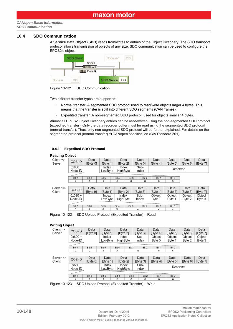
CANopen Basic InformationSDO Communication
© 2012 maxon motor. Subject to change without prior notice.
maxon motor control10-148 Document ID: rel2946 EPOS2 Positioning Controllers
Edition: February 2012 EPOS2 Application Notes Collection
10.4 SDO CommunicationA Service Data Object (SDO) reads from/writes to entries of the Object Dictionary. The SDO transport protocol allows transmission of objects of any size. SDO communication can be used to configure the EPOS2’s object.
Figure 10-121 SDO Communication
Two different transfer types are supported:
• Normal transfer: A segmented SDO protocol used to read/write objects larger 4 bytes. This means that the transfer is split into different SDO segments (CAN frames).
• Expedited transfer: A non-segmented SDO protocol, used for objects smaller 4 bytes.
Almost all EPOS2 Object Dictionary entries can be read/written using the non-segmented SDO protocol (expedited transfer). Only the data recorder buffer must be read using the segmented SDO protocol (normal transfer). Thus, only non-segmented SDO protocol will be further explained. For details on the segmented protocol (normal transfer) CANopen specification (CiA Standard 301).
10.4.1 Expedited SDO Protocol
Reading Object
Figure 10-122 SDO Upload Protocol (Expedited Transfer) – Read
Writing Object
Figure 10-123 SDO Upload Protocol (Expedited Transfer) – Write

CANopen Basic InformationSDO Communication
© 2012 maxon motor. Subject to change without prior notice.
maxon motor controlEPOS2 Positioning Controllers Document ID: rel2946 10-149EPOS2 Application Notes Collection Edition: February 2012
Abort SDO Protocol (in Case of Error)
Figure 10-124 SDO Upload Protocol (Expedited Transfer) – Abort
NoteFor detailed descriptions of “Abort Codes” FwSpec.
Table 10-140 SDO Transfer Protocol – Legend
Overview on important Command Specifier ([Byte 0] Bit 7…5)
Table 10-141 Command Specifier (Overview)
Legend
ccs client command specifier (Bit 7…5)
scs server command specifier (Bit 7…5)
X not used (always “0”)
nOnly valid if e = 1 and s = 1, otherwise 0. If valid, it indicates the number of bytes in Data [Byte 4…7] that do not contain data. Bytes [8 - n, 7] do not contain segment data.
e Transfer type (0: normal transfer; 1: expedited transfer)
s Size indicator (0: data set size is not indicated; 1: data set size is indicated)
Type Length Sending Data [Byte 0] Receiving Data [Byte 0]
ReadingObject
1 Byte 40 4F
2 Byte 40 4B
3 Byte 40 43
WritingObject
1 Byte 2F (or 22) 60
2 Byte 2B (or 22) 60
4 Byte 23 (or 22) 60
not defined 22 60

CANopen Basic InformationSDO Communication
© 2012 maxon motor. Subject to change without prior notice.
maxon motor control10-150 Document ID: rel2946 EPOS2 Positioning Controllers
Edition: February 2012 EPOS2 Application Notes Collection
10.4.2 SDO Communication Examples
Read “Current Regulator P-Gain” (Index 0x60F6, Subindex 0x01) from node 1:
Table 10-142 Example “Read”
Write “Current Regulator P-Gain” (Index 0x60F6, Subindex 0x01) to node 1:
Table 10-143 Example “Write”
Read “Unknown Object” (Index 0x2000, Subindex 0x08) from node 1:
Table 10-144 Example “Read”
CANopen Sending SDO Frame CANopen Receiving SDO Frame
COD-ID 0x601 0x600 + Node ID COD-ID 0x581 0x580 + Node ID
Data [0] 0x40 ccs =2 Data [0] 0x4B scs = 2, n = 2, e = 1, s = 1
Data [1] 0xF6 Index LowByte Data [1] 0xF6 Index LowByte
Data [2] 0x60 Index HighByte Data [2] 0x60 Index HighByte
Data [3] 0x01 Subindex Data [3] 0x01 Subindex
Data [4] 0x00 reserved Data [4] 0x90 P-Gain LowByte
Data [5] 0x00 reserved Data [5] 0x01 P-Gain HighByte
Data [6] 0x00 reserved Data [6] 0x00 reserved
Data [7] 0x00 reserved Data [7] 0x00 reserved
Current Regulator P-Gain: 0x00000190 = 400
CANopen Sending SDO Frame CANopen Receiving SDO Frame
COD-ID 0x601 0x600 + Node ID COD-ID 0x581 0x580 + Node ID
Data [0] 0x2B ccs = 1, n = 2, e = 1, s = 1 Data [0] 0x60 scs = 3
Data [1] 0xF6 Index LowByte Data [1] 0xF6 Index LowByte
Data [2] 0x60 Index HighByte Data [2] 0x60 Index HighByte
Data [3] 0x01 Subindex Data [3] 0x01 Subindex
Data [4] 0x12 P-Gain LowByte Data [4] 0x00 reserved
Data [5] 0x34 P-Gain HighByte Data [5] 0x00 reserved
Data [6] 0x00 reserved Data [6] 0x00 reserved
Data [7] 0x00 reserved Data [7] 0x00 reserved
Current Regulator P-Gain: new value
CANopen Sending SDO Frame CANopen Receiving SDO Frame
COD-ID 0x601 0x600 + Node ID COD-ID 0x581 0x580 + Node ID
Data [0] 0x40 ccs =2 Data [0] 0x80 scs = 3
Data [1] 0x00 Index LowByte Data [1] 0x00 Index LowByte
Data [2] 0x20 Index HighByte Data [2] 0x20 Index HighByte
Data [3] 0x08 Subindex Data [3] 0x08 Subindex
Data [4] 0x00 reserved Data [4] 0x11 Abort Code [Byte 0]
Data [5] 0x00 reserved Data [5] 0x00 Abort Code [Byte 1]
Data [6] 0x00 reserved Data [6] 0x09 Abort Code [Byte 2]
Data [7] 0x00 reserved Data [7] 0x06 Abort Code [Byte 3]
Abort code: 0x06090011 the last read or write command had a wrong object subindex.

CANopen Basic InformationPDO Communication
© 2012 maxon motor. Subject to change without prior notice.
maxon motor controlEPOS2 Positioning Controllers Document ID: rel2946 10-151EPOS2 Application Notes Collection Edition: February 2012
10.5 PDO CommunicationProcess Data Objects (PDOs) – unconfirmed services containing no protocol overhead – are used for fast data transmission (real-time data) with a high priority. Consequently, they represent an extremely fast and flexible method to transmit data from one node to any number of other nodes. PDOs may con-tain up to 8 data bytes that can be specifically compiled and confirmed to suit own requirements. Each PDO has a unique identifier and is transmitted by only one node, but it can be received by more than one (producer/consumer communication).
The CANopen network management is node-oriented and follows a master/slave structure. It requires one device in the network, which serves as NMT (Network Management) Master. The other nodes are NMT Slaves.
Figure 10-125 Network Management (NMT)
The CANopen NMT Slave devices implement a state machine that automatically brings every device to “Pre-Operational” state, once powered and initialized. In this state, the node may be configured and parameterized via SDO (e.g. using a configuration tool), PDO communication is not permitted. Thus, to switch from “Pre-Operational” to “Operational”, you will need to send the “Start Remote Node Protocol”. For detailed information on NMT Services separate document «EPOS2 Communication Guide».
Table 10-145 NMT Functionality
Figure 10-126 NMT Slave State Diagram
Function COB-IDCS
(Byte 0)Node ID(Byte 1)
Functionality
StartRemote NodeProtocol
0 0x01 0 (all)All EPOS2 (all CANopen nodes) will enter NMT State “Operational”.
0 0x01 nThe EPOS2 (or CANopen node) with Node ID n will enter NMT State “Operational”.
EnterPre-OperationalProtocol
0 0x80 0 (all)All EPOS2 (all CANopen nodes) will enter NMT State “Pre-Operational”.
0 0x80 nThe EPOS2 (or CANopen node) with Node ID n will enter NMT State “Pre-Operational”.

CANopen Basic InformationPDO Communication
© 2012 maxon motor. Subject to change without prior notice.
maxon motor control10-152 Document ID: rel2946 EPOS2 Positioning Controllers
Edition: February 2012 EPOS2 Application Notes Collection
10.5.1 PDO Transmissions
PDO transmissions may be driven by remote requests, event triggered and actuated by Sync message received:
• Remotely requested:Another device may initiate the transmission of an asynchronous PDO by sending a remote transmission request (remote frame).
• Event triggered (only Transmit PDOs):An event of a mapped object (e.g. velocity changed) will cause the transmission of the TxPDO. Subindex 3h of object “Transmit PDO X Parameter” contains the inhibit time, which represents the minimum interval for PDO transmission. The value is defined as a multiple of 100 us.
• Synchronous transmission:In order to initiate simultaneous sampling of input values of all nodes, a periodically transmitted Sync message is required. Synchronous PDO transmission takes place in cyclic and acyclic transmission mode. Cyclic transmission means that the node waits for the Sync message after which it sends its measured values. Its PDO transmission type number (1…240) indicates the Sync rate it listens to (the number of Sync messages the node waits before next transmission of its values). The EPOS supports only Sync rates of 1.
10.5.2 PDO Mapping
Default application objects’ mapping as well as the supported transmission mode is described in the Object Dictionary for each PDO. PDO identifiers may have high priority to guarantee short response time. PDO transmission is not confirmed. PDO mapping defines the application objects to be transmitted within a PDO. It describes sequence and length of the mapped application objects. A device supporting variable mapping of PDOs must support this during the Pre-Operational state. If dynamic mapping dur-ing Operational state is supported, the SDO Client is responsible for data consistency.
Figure 10-127 PDO Mapping

CANopen Basic InformationPDO Communication
© 2012 maxon motor. Subject to change without prior notice.
maxon motor controlEPOS2 Positioning Controllers Document ID: rel2946 10-153EPOS2 Application Notes Collection Edition: February 2012
10.5.3 PDO Configuration
For PDO Configuration, the device must be in Pre-Operational state!
The following section will explain how to configuration must be implemented step-by-step. Use «EPOS Studio» for all changes in the Object Dictionary described below. For each step, an example quotes “Receive PDO 1” and “Node 1”.
10.5.3.1 Step 1: Configure COB-ID
The default value of the COB-ID depends on the Node ID (Default COB-ID = PDO-Offset + Node ID). Otherwise, the COB-ID can be set in a defined range. Below table shows all default COB-IDs and their ranges:
Table 10-146 COB-IDs – Default Values and Value Range
Changed COB-IDs can be reset by “Restore Default PDO COB-IDs” using context menu of ¤Object Dic-tionary¤ view in «EPOS Studio».
10.5.3.2 Step 2: Set Transmission Type
Object Index SubindexDefault
COB-ID Node 1
TxPDO 1 0x1800 0x01 0x181
TxPDO 2 0x1801 0x01 0x281
TxPDO 3 0x1802 0x01 0x381
TxPDO 4 0x1803 0x01 0x481
RxPDO 1 0x1400 0x01 0x201
RxPDO 2 0x1401 0x01 0x301
RxPDO 3 0x1402 0x01 0x401
RxPDO 4 0x1403 0x01 0x501
Example: Object “COB-ID used by RxPDO 1” (Index 0x1400, Subindex 0x01):
Default COB ID RxPDO 1In Range COB ID RxPDO 1
= 0x200 + Node ID = 0x201= 0x233
Type 0x01 TxPDOs Data is sampled and transmitted after the occurrence of the SYNC.
RxPDOs Data is passed on to the EPOS2 and transmitted after the occurrence of the SYNC.
Type 0xFD TxPDOs Data is sampled and transmitted after the occurrence of a remote transmission request (RTR).
Type 0xFF TxPDOs Data is sampled and transmitted after the occurrence of a remote transmission request or an internal event (value changed).
RxPDOs Data is directly passed on to the EPOS2 application.
Example: Object “Transmission Type” (Index 0x1400, Subindex 0x02)Value = 0xFF

CANopen Basic InformationPDO Communication
© 2012 maxon motor. Subject to change without prior notice.
maxon motor control10-154 Document ID: rel2946 EPOS2 Positioning Controllers
Edition: February 2012 EPOS2 Application Notes Collection
10.5.3.3 Step 3: Number of Mapped Application Objects
Disable the PDO by wiring zero to object “Number of Mapped Application Objects in…”.
10.5.3.4 Step 4: Mapping Objects
Set value from an object.
NoteFor details on all mappable objects FwSpec, chapters “Receive PDO… Parameter” and “Transmit PDO… Parameter”.
10.5.3.5 Step 5: Number of mapped Application Objects
Enable PDO by writing the value of the number of objects in object “Number of Mapped Application Objects in…”.
10.5.3.6 Step 6: Activate Changes
Changes will directly be activated.
Execute menu item ¤Save All Parameters¤ in the context menu of the used node («EPOS Studio» \ Navigation Window \ Workspace or Communication) or in the context menu in the view “Object Diction-ary”.
Example: Object “Number of Mapped Application Objects in RxPDO 1” (Index 0x1600, Subindex 0x00)Value = 0x00
Example: Object1 “1st Mapped Object in RxPDO 1” (Index 0x1600, Subindex 0x01)Object2 “2nd Mapped Object in RxPDO 1” (Index 0x1600, Subindex 0x02)Object3 “3rd Mapped Object in RxPDO 1” (Index 0x1600, Subindex 0x03)
RxPDO 1 # Mapped Object
1 Object_1 = 0x60400010 Controlword (16-bit)
2 Object_2 = 0x607A0020 Target Position (32-bit)
3 Object_3 = 0x60FB0210 Position Regulator I-Gain (16-bit)
Example: Object “Number of Mapped Application Objects in RxPDO 1” (Index 0x1600, Subindex 0x00)

CANopen Basic InformationNode Guarding Protocol
© 2012 maxon motor. Subject to change without prior notice.
maxon motor controlEPOS2 Positioning Controllers Document ID: rel2946 10-155EPOS2 Application Notes Collection Edition: February 2012
10.6 Node Guarding ProtocolUsed to detect absent devices that do not transmit PDOs regularly (e.g. because of bus-off). The NMT Master can manage a database where, among other information, expected states of all connected devices are recorded, which is known as Node Guarding. With cyclic Node Guarding, the NMT Master regularly polls its NMT Slaves. To detect the absence of the NMT Master, the slaves test internally, whether Node Guarding is taking place in the defined time interval (Life Guarding).
Node Guarding is initiated by the NMT Master in Pre-Operational state of the slave by transmitting a Remote Frame. Node Guarding is also activated if Stopped State is active.
Legend: 1) Data Field / 2) Node Guard Time / 3) Node/Life Guarding Event
Figure 10-128 Node Guarding Protocol – Timing Diagram
Data Field
Holds the NMT State. Upon receipt of a node guard answer, bit 8 toggles between 0x00 and 0x80. Thus, the data field supports the following values:
Table 10-147 Node Guarding Protocol – Data Field
Node Guard Time
Is calculated as follows:
Value Toggle EPOS2 NMT State
0x04 not set Stopped
0x84 set Stopped
0x05 not set Operational
0x85 set Operational
0x7F not set Pre-Operational
0xFF set Pre-Operational
NodeGuardTime GuardTime LifeTimeFactor⋅=

CANopen Basic InformationNode Guarding Protocol
© 2012 maxon motor. Subject to change without prior notice.
maxon motor control10-156 Document ID: rel2946 EPOS2 Positioning Controllers
Edition: February 2012 EPOS2 Application Notes Collection
Node / Life Guarding Event
In case EPOS2 misses the Remote Transmit Request (RTR), it will change it’s device state to error (Node Guarding Error).
In case the answer is missed by the Master System, it may react with the Node Guarding Event.

CANopen Basic InformationHeartbeat Protocol
© 2012 maxon motor. Subject to change without prior notice.
maxon motor controlEPOS2 Positioning Controllers Document ID: rel2946 10-157EPOS2 Application Notes Collection Edition: February 2012
10.7 Heartbeat ProtocolThe Heartbeat Protocol has a higher priority than the Node Guarding Protocol, if both are enabled, only the Heartbeat Protocol is supported. The EPOS2 transmits a cyclic heartbeat message if the Heartbeat Protocol is enabled (Heartbeat Producer Time 0 = Disabled / greater than 0 = enabled). The Heartbeat Consumer guards receipt of the Heartbeat within the Heartbeat Consumer Time. If the Heartbeat Pro-ducer Time is configured in EPOS2, it will start immediately with the Heartbeat Protocol.
Legend: 1) Data Field / 2) Heartbeat Producer and Heartbeat Consumer Time / 3) Hearbeat Event
Figure 10-129 Heartbeat Protocol – Timing Diagram
Data Field
Holds the NMT State. Each time the value of toggle between 0x00 and 0x80. Therefore the following values for the data field are possible:
Table 10-148 Heartbeat Protocol – Data Field
Heartbeat Producer Time and Heartbeat Consumer Time
The Heartbeat Consumer Time must be longer than the Heartbeat Producer Time because of genera-
tion, sending and indication time ( ). Each indication of the Master resets the Heartbeat Consumer Time.
Heartbeat Event
If EPOS2 is in an unknown state (e.g. supply voltage failure), the Heartbeat Protocol cannot be sent to the Master. The Master will recognize this event upon elapsed Heartbeat Consumer Time and will gen-erate a Heartbeat Event.
Value EPOS2 NMT State
0x00 Bootup
0x04 Stopped
0x05 Operational
0xFF Pre-Operational
HeartbeatConsumerTime HeartbeatProducerTime 5ms+≥

CANopen Basic InformationHeartbeat Protocol
© 2012 maxon motor. Subject to change without prior notice.
maxon motor control10-158 Document ID: rel2946 EPOS2 Positioning Controllers
Edition: February 2012 EPOS2 Application Notes Collection

USB or RS232 to CAN GatewayIn Brief
© 2012 maxon motor. Subject to change without prior notice.
maxon motor controlEPOS2 Positioning Controllers Document ID: rel2946 11-159EPOS2 Application Notes Collection Edition: February 2012
11 USB or RS232 to CAN Gateway
11.1 In BriefA wide variety of operating modes permit flexible configuration of drive and automation systems by using positioning, speed and current regulation. The built-in CANopen interface allows networking to multiple axes drives as well as online commanding by CAN bus master units.
For simple point-to-point communication, EPOS2 also supports an USB or RS232 interface. In order to access a network using USB or RS232 protocols, EPOS2 includes an USB-to-CANopen, respectively a RS232-to-CANopen gateway functionality.
11.1.1 Objective
The present Application Note explains the functionality of the built-in communication gateway USB to CANopen or RS232 to CANopen. Advantages and disadvantages of this communication structures are discussed.
Contents
11.2 Communication Structure . . . . . . . . . . . . . . . . . . . . . . . . . . . . . . . . . . . . . . . . . . . . . . . . . . . . 11-160
11.3 Communication Examples . . . . . . . . . . . . . . . . . . . . . . . . . . . . . . . . . . . . . . . . . . . . . . . . . . . 11-161
11.4 Command Translation . . . . . . . . . . . . . . . . . . . . . . . . . . . . . . . . . . . . . . . . . . . . . . . . . . . . . . 11-165
11.6 Timing . . . . . . . . . . . . . . . . . . . . . . . . . . . . . . . . . . . . . . . . . . . . . . . . . . . . . . . . . . . . . . . . . . . 11-166
11.7 Conclusion . . . . . . . . . . . . . . . . . . . . . . . . . . . . . . . . . . . . . . . . . . . . . . . . . . . . . . . . . . . . . . . 11-167
11.1.2 Scope
Table 11-149 USB or RS232 to CAN Gateway – covered Hardware and required Documents
11.1.3 Tools
Table 11-150 USB or RS232 to CAN Gateway – recommended Tools
Hardware Order # Firmware Version Reference
EPOS2 2110hFirmware SpecificationCommunication Guide
EPOS2 70/10 375711 2120h or higher
EPOS2 50/5 347717 2110h or higher
EPOS2 Module 36/2 360665 2110h or higher
EPOS2 24/5 367676 2110h or higher
EPOS2 24/2380264390003390438
2121h or higher
Tools Description
Software «EPOS Studio» Version 1.41 or higher

USB or RS232 to CAN GatewayCommunication Structure
© 2012 maxon motor. Subject to change without prior notice.
maxon motor control11-160 Document ID: rel2946 EPOS2 Positioning Controllers
Edition: February 2012 EPOS2 Application Notes Collection
11.2 Communication StructureUsing the gateway functionality, the master can access all other EPOS2 devices connected to the CAN Bus via USB port or RS232 interface of the gateway device. Even other CANopen devices (I/O mod-ules) supporting the CANopen standard CiA DS 301 may be accessed.
Figure 11-130 Gateway Communication Structure
Communication data are exchanged between USB/RS232 master and the gateway using a maxon-spe-cific USB/RS232 protocol. The data between the gateway and the addressed device are exchanged using the CANopen SDO protocol according to the CiA Standard DS 301.
For details on CAN bus wiring chapter “10 CANopen Basic Information” on page 10-139.
Table 11-151 Communication Data Exchange
Step Protocol Sender Receiver Description
1
USB [maxon-specific]or
RS232 [maxon- specific]
USB or RS232 Master
EPOS2 ID 1, Gateway
Command including the node ID is sent to the device working as a gateway. The gateway decides whether to execute the command or to translate and forward it to the CAN bus.
Criteria:Node ID = 0 (Gateway)Node ID = DIP switchelse
Execute Execute Forward to CAN
2 CANopen [SDO]EPOS2 ID 1, Gateway
EPOS2 ID 2
The gateway is forwarding the command to the CAN network. The USB/RS232 command is translated to a CANopen SDO service.
3 CANopen [SDO]EPOS2 ID 2
EPOS2 ID 1, Gateway
The EPOS2 ID 2 is executing the command and sending the corresponding CAN frame back to the gateway.
4
USB [maxon specific] or
RS232 [maxon specific]
EPOS2 ID 1, Gateway
USB or RS232 Master
The gateway is receiving the CAN frame corresponding to the SDO service. This CAN frame is translated back to the USB/RS232 frame and sent back to the USB/RS232 master.

USB or RS232 to CAN GatewayCommunication Examples
© 2012 maxon motor. Subject to change without prior notice.
maxon motor controlEPOS2 Positioning Controllers Document ID: rel2946 11-161EPOS2 Application Notes Collection Edition: February 2012
11.3 Communication ExamplesThe examples employ following abbreviations:
Table 11-152 SDO Transfer Protocol – Legend
11.3.1 USB
Figure 11-131 Communication via USB (Example)
Legend
ccs client command specifier (Bit 7…5)
scs server command specifier (Bit 7…5)
X not used (always “0”)
nOnly valid if e = 1 and s = 1, otherwise 0. If valid, it indicates the number of bytes in Data [Byte 4…7] that do not contain data. Bytes [8 - n, 7] do not contain segment data (Bit 3 and 2).
e Transfer type (0: normal transfer; 1: expedited transfer) (Bit 1)
s Size indicator (0: data set size is not indicated; 1: data set size is indicated) (Bit 0)
Object: DeviceType, Index 0x1000, Subindex 0x00
Node: 2
USB Command: ReadObject
CANopen Service: SDO Upload (Expedited Transfer)

USB or RS232 to CAN GatewayCommunication Examples
© 2012 maxon motor. Subject to change without prior notice.
maxon motor control11-162 Document ID: rel2946 EPOS2 Positioning Controllers
Edition: February 2012 EPOS2 Application Notes Collection
Table 11-153 Communication via USB (Example) – Steps 1/2
Table 11-154 Communication via USB (Example) – Steps 3/4
Step 1: USB Sending Frames Step 2: CANopen Sending SDO Frame
DLE 0x90 Data Link Escape COB-ID 0x602 0x600 + Node ID
STX 0x02 Start of Text Data[0] 0x40 ccs = 2
OpCode 0x10 ReadObject command Data[1] 0x00 Index Byte 0
Len 0x02 2 Data Words Data[2] 0x10 Index Byte 1
Data[0] 0x00 Index Byte 0 Data[3] 0x00 Sub Index
Data[1] 0x10 Index Byte 1 Data[4] 0x00 reserved
Data[2] 0x00 Sub Index Data[5] 0x00 reserved
Data[3] 0x02 Node Id Data[6] 0x00 reserved
CRC[0] 0xDF Checksum Byte 0 Data[7] 0x00 reserved
CRC[1] 0xF2 Checksum Byte 1
Step 4: USB Receiving Frame Step 3: CANopen Receiving SDO Frame
DLE 0x90 Data Link Escape COB-ID 0x582 0x580 + Node ID
STX 0x02 Start of Text Data[0] 0x43 scs = 2, n = 0, e = 1, s = 1
OpCode 0x00 Answer to ReadObject Data[1] 0x00 Index LowByte
Len 0x04 4 Data Words Data[2] 0x10 Index HighByte
Data[0] 0x00 ErrorCode Byte 0 Data[3] 0x00 Sub Index
Data[1] 0x00 ErrorCode Byte 1 Data[4] 0x92 DeviceType Byte 1
Data[2] 0x00 ErrorCode Byte 2 Data[5] 0x01 DeviceType Byte 2
Data[3] 0x00 ErrorCode Byte 3 Data[6] 0x02 DeviceType Byte 3
Data[4] 0x92 DeviceType Byte 0 Data[7] 0x00 DeviceType Byte 4
Data[5] 0x01 DeviceType Byte 1
Data[6] 0x02 DeviceType Byte 2
Data[7] 0x00 DeviceType Byte 3
CRC[0] 0x9A Checksum Byte 0
CRC[1] 0xED Checksum Byte 1

USB or RS232 to CAN GatewayCommunication Examples
© 2012 maxon motor. Subject to change without prior notice.
maxon motor controlEPOS2 Positioning Controllers Document ID: rel2946 11-163EPOS2 Application Notes Collection Edition: February 2012
11.3.2 RS232
Figure 11-132 Communication via RS232 (Example)
Object: DeviceType, Index 0x1000, Subindex 0x00
Node: 2
USB Command: ReadObject
CANopen Service: SDO Upload (Expedited Transfer)
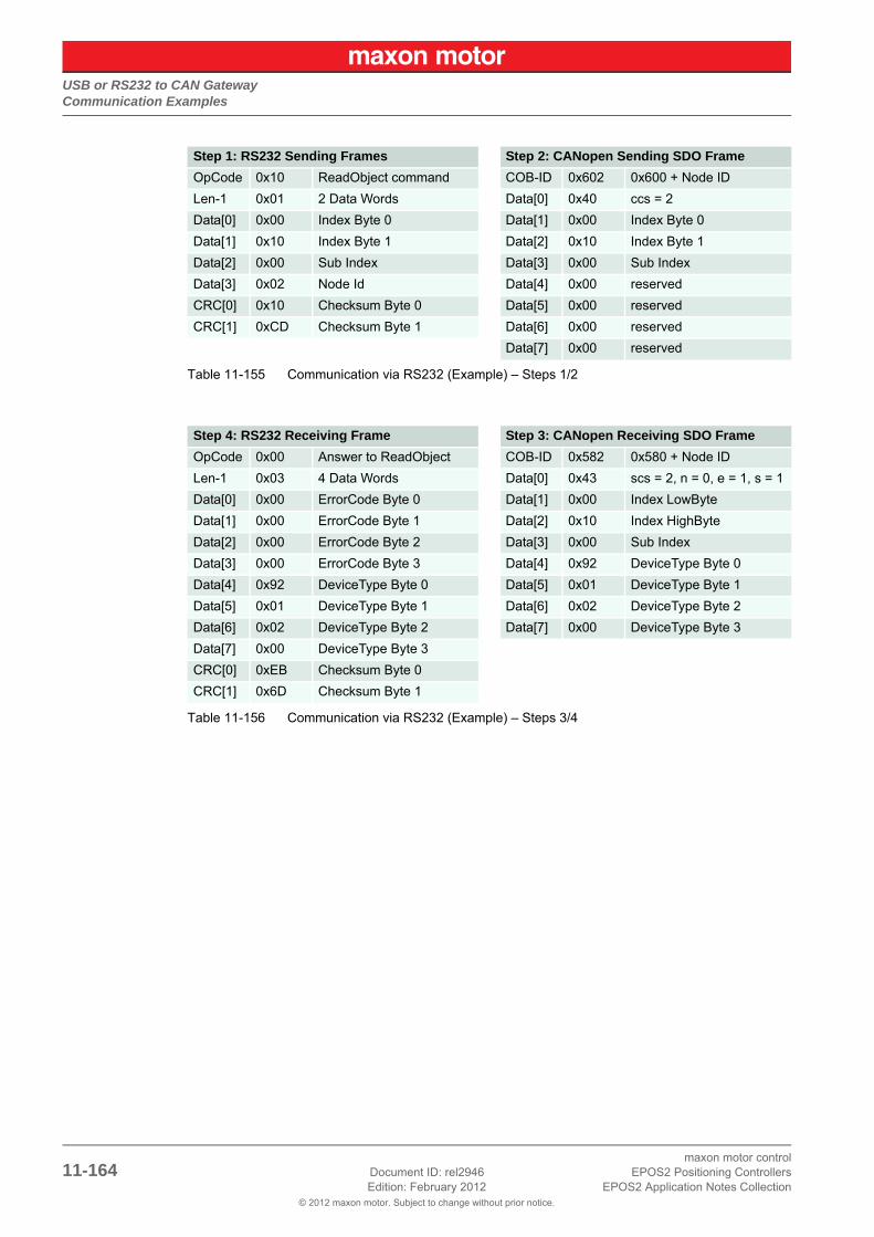
USB or RS232 to CAN GatewayCommunication Examples
© 2012 maxon motor. Subject to change without prior notice.
maxon motor control11-164 Document ID: rel2946 EPOS2 Positioning Controllers
Edition: February 2012 EPOS2 Application Notes Collection
Table 11-155 Communication via RS232 (Example) – Steps 1/2
Table 11-156 Communication via RS232 (Example) – Steps 3/4
Step 1: RS232 Sending Frames Step 2: CANopen Sending SDO Frame
OpCode 0x10 ReadObject command COB-ID 0x602 0x600 + Node ID
Len-1 0x01 2 Data Words Data[0] 0x40 ccs = 2
Data[0] 0x00 Index Byte 0 Data[1] 0x00 Index Byte 0
Data[1] 0x10 Index Byte 1 Data[2] 0x10 Index Byte 1
Data[2] 0x00 Sub Index Data[3] 0x00 Sub Index
Data[3] 0x02 Node Id Data[4] 0x00 reserved
CRC[0] 0x10 Checksum Byte 0 Data[5] 0x00 reserved
CRC[1] 0xCD Checksum Byte 1 Data[6] 0x00 reserved
Data[7] 0x00 reserved
Step 4: RS232 Receiving Frame Step 3: CANopen Receiving SDO Frame
OpCode 0x00 Answer to ReadObject COB-ID 0x582 0x580 + Node ID
Len-1 0x03 4 Data Words Data[0] 0x43 scs = 2, n = 0, e = 1, s = 1
Data[0] 0x00 ErrorCode Byte 0 Data[1] 0x00 Index LowByte
Data[1] 0x00 ErrorCode Byte 1 Data[2] 0x10 Index HighByte
Data[2] 0x00 ErrorCode Byte 2 Data[3] 0x00 Sub Index
Data[3] 0x00 ErrorCode Byte 3 Data[4] 0x92 DeviceType Byte 0
Data[4] 0x92 DeviceType Byte 0 Data[5] 0x01 DeviceType Byte 1
Data[5] 0x01 DeviceType Byte 1 Data[6] 0x02 DeviceType Byte 2
Data[6] 0x02 DeviceType Byte 2 Data[7] 0x00 DeviceType Byte 3
Data[7] 0x00 DeviceType Byte 3
CRC[0] 0xEB Checksum Byte 0
CRC[1] 0x6D Checksum Byte 1

USB or RS232 to CAN GatewayCommand Translation
© 2012 maxon motor. Subject to change without prior notice.
maxon motor controlEPOS2 Positioning Controllers Document ID: rel2946 11-165EPOS2 Application Notes Collection Edition: February 2012
11.4 Command TranslationThe USB/RS232 command set is designed approximate to CANopen services. All USB/RS232 com-mands have a directly corresponding service in the CAN network, thus simplifying the gateway function-ality. Between two subsequent USB/RS232 commands, no data must be stored or buffered, thus mini-mizing Gateway’s memory use. All received data are directly forwarded to the CAN bus.
Table 11-157 Command Translation – USB/RS232 to CANopen Service
11.5 Limiting FactorsThe number of segments has a big influence on the data exchange performance. Exchanging data directly with a device connected to RS232 (no gateway), a data segment can transfer up to 63 Bytes per command, thus for 1kB of data, 17 commands must be sent. Compared to sending data to a device addressed via gateway, 147 commands must be sent. CANopen services (normal transfer) allow only 7 bytes to be transferred in a segment. Therefore, the CANopen segment limits also the RS232 segment. Please keep in mind; the gateway is not capable of buffering data nor to split data into several CANopen services.
Considering the segment size, CANopen is the limiting factor for the communication performance. Con-sidering the bit rate of the two field buses, the RS232 interface is the limiting factor. Communication via gateway cannot take advantage of the CAN bus’ high bit rate, it is limited by the RS232’s slow bit rate and the small CANopen segment size.
Table 11-158 USB or RS232 to CAN Gateway – Limiting Factors
However, these limiting factors must be put into perspective, because most of the elements in the Object Dictionary are 32-bit parameters, or even smaller. Thus, segmented transfer is used very rarely. Segmented transfer will only be used to read the data recorder’s data buffer or for firmware download.
USB/RS232 Command CANopen Service
ReadObject Initiate SDO Upload / Expedited Transfer
InitiateSegmentedRead Initiate SDO Upload / Normal Transfer
SegmentRead Upload SDO Segment
WriteObject Initiate SDO Download / Expedited Transfer
InitiateSegmentedWrite Initiate SDO Download / Normal Transfer
SegmentWrite Download SDO Segment
SendNMTService NMT Service
ReadLSSFrame LSS Service
SendLSSFrame LSS Service
Description USB Protocol RS232 Protocol CANopenUSB to CANopen Gateway
RS232 to CANopen Gateway
Max. bit rate 1 MBit/s 115.2 kBit/s 1 MBit/s 1 MBit/s 115.2 kBit/s
Max. segment size
63 Bytes 63 Bytes 7 Bytes 7 Bytes 7 Bytes
Conclusion
Transfer Rate Fast Slow Fast Fast Slow
Segment Size Big Big Small Small Small

USB or RS232 to CAN GatewayTiming
© 2012 maxon motor. Subject to change without prior notice.
maxon motor control11-166 Document ID: rel2946 EPOS2 Positioning Controllers
Edition: February 2012 EPOS2 Application Notes Collection
11.6 Timing
11.6.1 RS232
The primary bottleneck in communication via RS232 to CANopen gateway is the RS232 bit rate. The maximum RS232 bit rate (115.2 kBit/s) is ten times smaller than the maximum CAN bit rate (1 MBit/s). The duration of the communication depends more or less on the RS232 bit rate used. The following tim-ing example shows communication delaying for addressing a device via the gateway.
Example
Table 11-159 RS232 to CAN Gateway – Timing
11.6.2 Timing Values
Measured values are based on PC using IXXAT card with driver VCI3.
Table 11-160 Timing – CAN Bus (CANopen SDO Services)
Table 11-161 Timing – USB
Test Platform Pentium 4, 2.66 GHz, Windows XP, EPOS_UserInterface
Command ReadObject, 32-Bit Object
RS232 Bit rate 38400 Bit/s (Default)
CAN Bit rate 1 MBit/s (Default)
Time via Gateway 10.125 ms (measured)
Time without Gateway 9.995 ms (measured)
Delay 130 μs
CANRead/Write 8-bit / 16-bit / 32-bit object
(2 CAN frames @ 8/8 bytes)Read/Write
(200 CAN frames @ 8/8 bytes)
Bit Rate Calculated Measured Calculated Measured
1 MBit/s 220 μs 794 μs 44 ms 159 ms
800 kBit/s 275 μs 850 μs 55 ms 170 ms
500 kBit/s 440 μs 1.0 ms 88 ms 204 ms
250 kBit/s 880 μs 1.5 ms 196 ms 307 ms
125 kBit/s 1.8 ms 2.4 ms 360 ms 488 ms
50 kBit/s 4.4 ms 5.3 ms 880 ms 1052 ms
20 kBit/s 11 ms 12.4 ms 2.2 s 2.5 s
USBRead/Write 8-bit / 16-bit / 32-bit object
(2 USB frames @ 10/14 bytes)Read/Write
(200 2 USB frames @ 10/14 bytes)
Bit Rate Calculated Measured Calculated Measured
1 MBit/s 2 ms 2.3 ms 400 ms 474 ms

USB or RS232 to CAN GatewayConclusion
© 2012 maxon motor. Subject to change without prior notice.
maxon motor controlEPOS2 Positioning Controllers Document ID: rel2946 11-167EPOS2 Application Notes Collection Edition: February 2012
Table 11-162 Timing – RS232 (maxon-specific protocol)
11.7 ConclusionThe gateway functionality enables easy connection to the CAN network without the need of a separate CAN interface card to monitor a CAN network. Also, wiring of the CAN network does not require altera-tion. By simply plugging the USB or RS232 cable into one of the EPOS2 Positioning Controllers, all other EPOS2 devices in the network can be controlled and monitored.
The delay in CAN communication can be neglected when considering the time needed with RS232 baud rate. Thus, the gateway does not slow down the RS232 communication. Thereby, it does not really make any difference (except in segmented transfers) whether the master is addressing a device in the CAN network directly via RS232 or via the gateway.
RS232Read/Write 8-bit / 16-bit / 32-bit object
(2 RS232 frames @ 10/14 bytes)Read/Write
(200 RS232 frames @ 10/14 bytes)
Bit Rate Calculated Measured Calculated Measured
115200 Bit/s 2.083 ms 3.9 ms 0.42 s 0.8 s
57600 Bit/s 4.16 ms 7.2 ms 0.83 s 1.4 s
38400 Bit/s 6.25 ms 10.4 ms 1.25 s 2.1 s
19200 Bit/s 12.5 ms 20.5 ms 2.5 s 4.1 s
14400 Bit/s 16.6 ms 27.2 ms 3.33 s 5.5 s
9600 Bit/s 34.47 ms 40.7 ms 6.89 s 8.2 s

USB or RS232 to CAN GatewayConclusion
© 2012 maxon motor. Subject to change without prior notice.
maxon motor control11-168 Document ID: rel2946 EPOS2 Positioning Controllers
Edition: February 2012 EPOS2 Application Notes Collection
• • p a g e i n t e n t i o n a l l y l e f t b l a n k • •

Data RecordingIn Brief
© 2012 maxon motor. Subject to change without prior notice.
maxon motor controlEPOS2 Positioning Controllers Document ID: rel2946 12-169EPOS2 Application Notes Collection Edition: February 2012
12 Data Recording
12.1 In BriefA wide variety of operating modes permit flexible configuration of drive and automation systems by using positioning, speed and current regulation. The built-in CANopen interface allows networking to multiple axes drives as well as online commanding by CAN bus master units.
EPOS and EPOS2 both feature a built-in data recorder to debug errors and to monitor motion control parameters and actual values.
12.1.1 Objective
The present Application Note explains the functionality of the built-in data recorder. Features and config-uration options are explained.
Contents
12.2 Overview. . . . . . . . . . . . . . . . . . . . . . . . . . . . . . . . . . . . . . . . . . . . . . . . . . . . . . . . . . . . . . . . . 12-170
12.3 Data Recorder Configuration . . . . . . . . . . . . . . . . . . . . . . . . . . . . . . . . . . . . . . . . . . . . . . . . . 12-173
12.4 Example: Data Recording in “Profile Position Mode” . . . . . . . . . . . . . . . . . . . . . . . . . . . . . . . 12-174
12.5 Data Recorder Specifications . . . . . . . . . . . . . . . . . . . . . . . . . . . . . . . . . . . . . . . . . . . . . . . . . 12-178
12.1.2 Scope
Table 12-163 Data Recording – covered Hardware and required Documents
Hardware Order # Firmware Version Reference
EPOS2 all Firmware Specification
EPOS2 70/10 375711 all
EPOS2 50/5 347717 all
EPOS2 Module 36/2 360665 all
EPOS2 24/5 367676 all
EPOS2 24/2380264390003390438
2121h or higher
EPOS all Firmware Specification
EPOS 70/10 300583 all
EPOS 24/1
280937302267302287317270
all
EPOS P 24/5 323232 all
MCD EPOS 60 W 326343 all
MCD EPOS P 60 W 315665 all

Data RecordingOverview
© 2012 maxon motor. Subject to change without prior notice.
maxon motor control12-170 Document ID: rel2946 EPOS2 Positioning Controllers
Edition: February 2012 EPOS2 Application Notes Collection
12.1.3 Tools
Table 12-164 Data Recording – recommended Tools
12.2 Overview
12.2.1 Launching the Data Recorder
1) Start «EPOS Studio».
2) Start Data Recorder – either click right ¤Selected Node¤ or click ¤Tools¤ in Navigation Window.
3) Following screen will be displayed:
Figure 12-133 Data Recorder Overview
Tools Description
Software «EPOS Studio» Version 1.41 or higher

Data RecordingOverview
© 2012 maxon motor. Subject to change without prior notice.
maxon motor controlEPOS2 Positioning Controllers Document ID: rel2946 12-171EPOS2 Application Notes Collection Edition: February 2012
12.2.2 Control Elements and their Function
Title Bar
Table 12-165 Data Recording – Title Bar
Options Bar
Table 12-166 Data Recording – Option Bar
Control Element Description / Function
Status
Displays data recorder’s status. The following states are possible:
Data Recorder RunningContinuous Acquisition Mode
Data are continuously recorded and displayed.
Data Recorder WaitingSingle Trigger Mode
On standby, waiting to receive a trigger to start a single data record (for trigger options page 12-174).
Data Recorder TriggeredSingle Trigger Mode
Sampling in process until data buffer is full.
Data Recorder StoppedSingle Trigger Mode orContinuous Acquisition Mode
Recording completed and stopped, results are being displayed.
Start
Commences sampling.In “Single Trigger Mode”, the data recorder is waiting for a trigger. In “Continuous Acquisition Mode”, the data recorder is continuously recording and displaying data.
Stop Stops sampling. Latest recorded data are being displayed.
Force trigger A trigger has been activated.
Control Element Description / Function
Display ModeLinear Mode To display data, linear interpolation will be used.
Sample & Hold Between samples, no interpolation will be used.
Available CurvesAvailable curves will be listed.Tick check box to show/untick to hide a curve in the display.
Cursor
Off No curser will be displayed.
Free Cursor Curser will appear, as soon as the mouse is moved.
Attached CursorMoving the mouse will attach the cursor to the selected curve. Use “Available Curves” to select another curve.
Update Display Last sampled data will be loaded and displayed.
Configure Recorder
To select sampled data and to configure the data recorder (“Data Recorder Configuration” on page 12-173).

Data RecordingOverview
© 2012 maxon motor. Subject to change without prior notice.
maxon motor control12-172 Document ID: rel2946 EPOS2 Positioning Controllers
Edition: February 2012 EPOS2 Application Notes Collection
Display
Table 12-167 Data Recording – Display
Context Menu
Table 12-168 Data Recording – Context Menu
Control Element Description / Function
ZoomZoom in: Click left and draw a rectangle over desired area – status indication (upper left corner) will change to “Zoomed”.Zoom out: Click right – status indication will disappear.
CursorIf activated, the cursor will appear as small circle. Cursor’s actual coordinates are displayed in the upper right corner.
Left / Right ScaleEach data set may be displayed in either left or right pane (Data Recorder Configuration).
Time Scale At bottom border with corresponding time base at lower right corner.
Legend Currently displayed curves’ legend appears in lower left corner.
Control Element Description / Function
Load Recorded Data
Load recorded data from file (*.rda).
Save & Export Recorded Data
Save recorded data to file in following file formats:
*.rda Binary Format (for use with «EPOS Studio»)
*.txt ASCII Text Format (for import in Microsoft Excel)
*.csvComma Separated Values (for import in Microsoft Excel)
*.bmp Bitmap Format
Auto Scale Select this option to automatically calculate optimal scale values.
Setup Scale Values
If “Auto Scale” is deselected, left/right pane and time scale can be defined manually.
Manual Open connected device’s online help manual.
Configure Recorder
To select sampled data and to configure data recorder (Data Recorder Configuration).
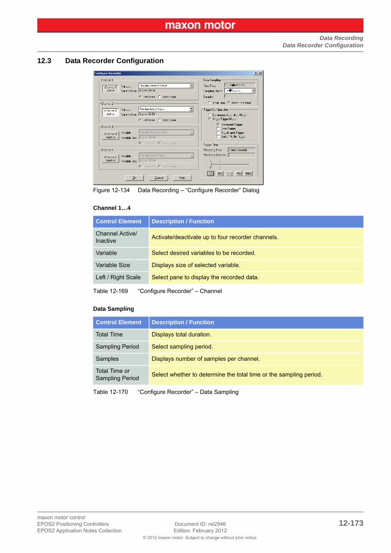
Data RecordingData Recorder Configuration
© 2012 maxon motor. Subject to change without prior notice.
maxon motor controlEPOS2 Positioning Controllers Document ID: rel2946 12-173EPOS2 Application Notes Collection Edition: February 2012
12.3 Data Recorder Configuration
Figure 12-134 Data Recording – “Configure Recorder” Dialog
Channel 1…4
Table 12-169 “Configure Recorder” – Channel
Data Sampling
Table 12-170 “Configure Recorder” – Data Sampling
Control Element Description / Function
Channel Active/Inactive
Activate/deactivate up to four recorder channels.
Variable Select desired variables to be recorded.
Variable Size Displays size of selected variable.
Left / Right Scale Select pane to display the recorded data.
Control Element Description / Function
Total Time Displays total duration.
Sampling Period Select sampling period.
Samples Displays number of samples per channel.
Total Time or Sampling Period
Select whether to determine the total time or the sampling period.

Data RecordingExample: Data Recording in “Profile Position Mode”
© 2012 maxon motor. Subject to change without prior notice.
maxon motor control12-174 Document ID: rel2946 EPOS2 Positioning Controllers
Edition: February 2012 EPOS2 Application Notes Collection
Trigger Configuration
Table 12-171 “Configure Recorder” – Trigger Configuration
Trigger Time
Table 12-172 “Configure Recorder” – Trigger Time
12.4 Example: Data Recording in “Profile Position Mode”
12.4.1 Step 1: Configure Data Recorder
1) Click ¤Configure Recorder¤ in the options bar or select ¤Configure Recorder¤ from the context menu.
Figure 12-135 Configure Data Recorder
2) Select the following variables:
• Position Demand Value
• Position Actual Value
• Velocity Actual Value
• Current Actual Value
3) Select a sampling period of 1 ms.
4) Select ¤Single Trigger Mode¤ and tick ¤Movement Trigger¤.
Control Element Description / Function
Continuous Acquisition Mode
Data will continuously be recorded.
Single Trigger Mode
Movement TriggerA trigger is activated upon every start of a movement.
Error Trigger A trigger is activated upon an occurring error.
Digital Input TriggerA trigger is activated at an edge of a digital input.Note: In “Homing Mode”, also the current threshold will be interpreted as a trigger.
End of Profile TriggerA trigger is activated at the end of a movement profile.
Control Element Description / Function
Preceding Time
The lead time to be displayed prior activation of a trigger. “100%” permits display of data prior the trigger.Best Practice: Use the trigger time in combination with the error trigger to debug errors.
Preceding Samples
Displays the number of samples before the trigger.

Data RecordingExample: Data Recording in “Profile Position Mode”
© 2012 maxon motor. Subject to change without prior notice.
maxon motor controlEPOS2 Positioning Controllers Document ID: rel2946 12-175EPOS2 Application Notes Collection Edition: February 2012
5) Select a preceding time of 0 microseconds.
Figure 12-136 Select Configuration Options
6) Click ¤OK¤ to save settings.
12.4.2 Step 2: Execute Movement
1) Change the active view to “Profile Position Mode”.
2) Activate “Profile Position Mode”.
3) Enable the EPOS and start a relative movement.
Figure 12-137 Execute Movement
12.4.3 Step 3: Update Display
Change back to the view “Data Recording”. If the display does not automatically refresh, press ¤Update Display¤ button.
12.4.4 Step 4: Save recorded Data
1) Click right ¤Save & Export Recorded Data¤ to open context menu.
Figure 12-138 Save recorded Data

Data RecordingExample: Data Recording in “Profile Position Mode”
© 2012 maxon motor. Subject to change without prior notice.
maxon motor control12-176 Document ID: rel2946 EPOS2 Positioning Controllers
Edition: February 2012 EPOS2 Application Notes Collection
2) Select desired path.
3) Enter a file name.
4) Press ¤Save¤.
Figure 12-139 Save recorded Data
Best PracticeSave recorded data as ASCII text file or as bitmap!
12.4.5 Step 5: Analyze recorded Data
1) Select cursor mode ¤Attached Cursor¤.
2) Tick ¤Position Actual Value¤ in “Available Curves”.
3) Move cursor over the display and read the attached curve's values.
Figure 12-140 Analyze recorded Data

Data RecordingExample: Data Recording in “Profile Position Mode”
© 2012 maxon motor. Subject to change without prior notice.
maxon motor controlEPOS2 Positioning Controllers Document ID: rel2946 12-177EPOS2 Application Notes Collection Edition: February 2012
12.4.6 Step 6: Restart Data Recorder
Click ¤Start¤ to restart and prepare the data recorder for the next recording.
Figure 12-141 Restart Data Recorder

Data RecordingData Recorder Specifications
© 2012 maxon motor. Subject to change without prior notice.
maxon motor control12-178 Document ID: rel2946 EPOS2 Positioning Controllers
Edition: February 2012 EPOS2 Application Notes Collection
12.5 Data Recorder Specifications
12.5.1 Functionalities
Recorder
• Executed in current regulator (max 10 kHz sampling rate)
• Configurable sampling rate
• Total buffer size: 512 words
While the data recorder is running, data are sampled to a ring buffer until a trigger is set. After a trigger, data will be recorded until the buffer is full.
Variables
• Max. four variables of the Object Dictionary
• 16-bit and 32-bit variables are allowed (one word)
• 8-bit variables need 16-bits in the data recorder memory
Trigger
Following automatic trigger modes are supported:
• Manuel Trigger – set by communication
• Movement Trigger – set at movement start
• Error Trigger – set by error
• Digital Input Trigger – set by digital input
• End of Profile Trigger – set at movement stop
12.5.2 Object Description
12.5.2.1 Data Recorder Control
Description
The data recorder is controlled by write access.
Table 12-173 Data Recorder Control – Bits
Name Data Recorder Control
Index 0x2010
Subindex 0x00
Type UNSIGNED16
Access RW
Default Value 0
Value Range 0 3
Bit Description
15…2 reserved
10 = no trigger1 = force trigger
00 = stop recorder1 = start recorder

Data RecordingData Recorder Specifications
© 2012 maxon motor. Subject to change without prior notice.
maxon motor controlEPOS2 Positioning Controllers Document ID: rel2946 12-179EPOS2 Application Notes Collection Edition: February 2012
12.5.2.2 Data Recorder Configuration
Description
Configures the auto trigger functions.
Table 12-174 Data Recorder Configuration – Bits
12.5.2.3 Data Recorder Sampling Period
Description
Sampling period as a multiple of the current regulator cycle (n multiplied by 0.1ms).
12.5.2.4 Data Recorder Number of Preceding Samples
Description
Number of preceding samples defines the trigger position in the data recorder buffer.
Name Data Recorder Configuration
Index 0x2011
Subindex 0x00
Type UNSIGNED16
Access RW
Default Value 0
Value Range Table 12-174
Bit Description
15…4 reserved
3 1 = trigger at end of profile
2 1 = trigger upon digital input
1 1 = trigger by error state
0 1 = trigger at movement start
Name Data Recorder Sampling Period
Index 0x2012
Subindex 0x00
Type UNSIGNED16
Access RW
Default Value 10
Value Range 0 65535
Name Data Recorder Number of Preceding Samples
Index 0x2013
Subindex 0x00
Type UNSIGNED16
Access RW
Default Value 0
Value Range 0 65535

Data RecordingData Recorder Specifications
© 2012 maxon motor. Subject to change without prior notice.
maxon motor control12-180 Document ID: rel2946 EPOS2 Positioning Controllers
Edition: February 2012 EPOS2 Application Notes Collection
12.5.2.5 Data Recorder Number of Sampling Variables
Description
Number of variables (max. 4) to be recorded.
12.5.2.6 Data Recorder Index of Variables
Description
Index of Object Dictionary.
Related Objects
Data Recorder Subindex of Variables
Name Data Recorder Number of Sampling Variables
Index 0x2014
Subindex 0x00
Type UNSIGNED16
Access RW
Default Value 0
Value Range 0 4
Name Data Recorder Index of Variables
Index 0x2015
Number of entries 0x05
NamesData Recorder Index of Variable 1Data Recorder Index of Variable 2
Data Recorder Index of Variable 3Data Recorder Index of Variable 4
Index 0x2015
Subindex 0x01…0x04
Type UNSIGNED16
Access RW
Default Value 0
Value Range Object Dictionary

Data RecordingData Recorder Specifications
© 2012 maxon motor. Subject to change without prior notice.
maxon motor controlEPOS2 Positioning Controllers Document ID: rel2946 12-181EPOS2 Application Notes Collection Edition: February 2012
12.5.2.7 Data Recorder Subindex of Variables
Description
Subindex of Object Dictionary.
Related Objects
Data Recorder Index of Variables
12.5.2.8 Data Recorder Status
Description
Data recorder’s status.
Table 12-175 Data Recorder Status – Bits
Name Data Recorder Subindex of Variables
Index 0x2016
Number of entries 0x05
NamesData Rec… Subindex of Variable 1Data Rec… Subindex of Variable 2
Data Rec… Subindex of Variable 3Data Rec… Subindex of Variable 4
Index 0x2016
Subindex 0x01…0x04
Type UNSIGNED16
Access RW
Default Value 0
Value Range Object Dictionary
Name Data Recorder Status
Index 0x2017
Subindex 0x00
Type UNSIGNED16
Access RO
Default Value 0
Value Range Table 12-175
Bit Description
15…2 reserved
10 = not triggered1 = triggered
00 = stopped1 = running

Data RecordingData Recorder Specifications
© 2012 maxon motor. Subject to change without prior notice.
maxon motor control12-182 Document ID: rel2946 EPOS2 Positioning Controllers
Edition: February 2012 EPOS2 Application Notes Collection
12.5.2.9 Data Recorder Max. Number of Samples
Description
Defines maximal number of samples per variable. The parameter is dynamically calculated by the data recorder.
The maximal number of samples is the memory size (512 words) divided by the sum of the variable size (in words) of all configured variables.
Example:
Table 12-176 Data Recorder Max. Number of Samples – Example
12.5.2.10 Data Recorder Number of recorded Samples
Description
Offset to the start of the recorded data vector within the ring buffer.
Name Data Recorder max. Number of Samples
Index 0x2018
Subindex 0x00
Type UNSIGNED16
Access RO
Default Value 0
Value Range – –
Sum of Variable Size[word]
Example Number of Samples
11 x 16-bit variable
or1 x 8-bit variable
512
2 1 x 32-bit variable 256
3 1 x 16-bit and 1 x 32-bit variable 170
… … …
8 4 x 32-bit variables 64
Name Data Recorder Number of recorded Samples
Index 0x2019
Subindex 0x00
Type UNSIGNED16
Access RO
Default Value 0
Value Range – –

Data RecordingData Recorder Specifications
© 2012 maxon motor. Subject to change without prior notice.
maxon motor controlEPOS2 Positioning Controllers Document ID: rel2946 12-183EPOS2 Application Notes Collection Edition: February 2012
12.5.2.11 Data Recorder Data Buffer
Description
Memory for the different data recorder’s ring buffers. Memory allocation is dynamically calculated when the recorder is started.
Data Buffer Segmentation (Example: 2 x 16-bit variables, 1 x 32-bit variable)
Figure 12-142 Data Recorder Data Buffer – Segmentation
StartRingBuffer1 = 0
StartRingBuffer2 = MaxNbOfSamples * nbOfWords(Variable1)
StartRingBuffer3 = MaxNbOfSamples * (nbOfWords(Variable1) + nbOfWords(Variable2)
Name Data Recorder Data Buffer
Index 0x201B
Subindex 0x00
Type Domain
Access RO
Default Value 0
Value Range – –

Data RecordingData Recorder Specifications
© 2012 maxon motor. Subject to change without prior notice.
maxon motor control12-184 Document ID: rel2946 EPOS2 Positioning Controllers
Edition: February 2012 EPOS2 Application Notes Collection
• • p a g e i n t e n t i o n a l l y l e f t b l a n k • •

Extended Encoders ConfigurationIn Brief
© 2012 maxon motor. Subject to change without prior notice.
maxon motor controlEPOS2 Positioning Controllers Document ID: rel2946 13-185EPOS2 Application Notes Collection Edition: February 2012
13 Extended Encoders Configuration
13.1 In BriefIn addition to standard incremental digital encoders to detect the actual position, a number of other sen-sor types may be used:
• SSI absolute encoder (single or multi turn, 6 to 32 bit resolution, Gray or binary code, RS422)
• Analog incremental encoder (2-channel, max. 10 bit interpolation, Sinus-Cosinus 1 Vss)
• Digital incremental encoder (2-channel or 3-channel, up to 2 500 000 impulse, RS422)
13.1.1 Objective
The present Application Note explains the configuration of extended encoders and features “in practice examples” suitable for daily use.
Contents
13.2 Hardware Signals . . . . . . . . . . . . . . . . . . . . . . . . . . . . . . . . . . . . . . . . . . . . . . . . . . . . . . . . . . 13-186
13.3 Sensor Types . . . . . . . . . . . . . . . . . . . . . . . . . . . . . . . . . . . . . . . . . . . . . . . . . . . . . . . . . . . . . 13-189
13.4 Configuration Objects . . . . . . . . . . . . . . . . . . . . . . . . . . . . . . . . . . . . . . . . . . . . . . . . . . . . . . . 13-196
13.5 Application Examples . . . . . . . . . . . . . . . . . . . . . . . . . . . . . . . . . . . . . . . . . . . . . . . . . . . . . . . 13-203
13.1.2 Scope
Table 13-177 Extended Encoders Configuration – covered Hardware and required Documents
13.1.3 Tools
Table 13-178 Extended Encoders Configuration – recommended Tools
Hardware Order # Firmware Version Reference
EPOS2 2120h Firmware Specification
EPOS2 70/10 375711 2120h or higherCable Starting SetHardware Reference
EPOS2 50/5 347717 2120h or higherCable Starting SetHardware Reference
EPOS2 Module 36/2 360665 2120h or higher Hardware Reference
Tools Description
Crimper Molex hand crimper (63819-0000)
Software «EPOS Studio» Version 1.42 or higher

Extended Encoders ConfigurationHardware Signals
© 2012 maxon motor. Subject to change without prior notice.
maxon motor control13-186 Document ID: rel2946 EPOS2 Positioning Controllers
Edition: February 2012 EPOS2 Application Notes Collection
13.2 Hardware SignalsThe extended position sensors can be connected to the EPOS2 Positioning Controllers’s digital inputs and outputs.
13.2.1 EPOS2 70/10
Signal 2 Connector (J5A)
Contains differential “High Speed Command” digital inputs.
Additionally available are differential analog inputs.
Figure 13-143 EPOS2 70/10 – Signal 2 Connector (J5A)
Table 13-179 EPOS2 70/10 – Signal 2 Connector (J5A)
Pin Signal Description
1 +5VOUT Reference output voltage +5 V
2 A_Gnd Analog signal ground
3 AnIN2- Analog Input 2, negative signal
4 AnIN2+ Analog Input 2, positive signal
5 AnIN1- Analog Input 1, negative signal
6 AnIN1+ Analog Input 1, positive signal
7 D_Gnd Digital signal ground
8 D_Gnd Digital signal ground
9 DigIN8/ Digital Input 8 “High Speed Command” complement
10 DigIN8 Digital Input 8 “High Speed Command”
11 DigIN7/ Digital Input 7 “High Speed Command” complement
12 DigIN7 Digital Input 7 “High Speed Command”

Extended Encoders ConfigurationHardware Signals
© 2012 maxon motor. Subject to change without prior notice.
maxon motor controlEPOS2 Positioning Controllers Document ID: rel2946 13-187EPOS2 Application Notes Collection Edition: February 2012
Signal 3 Connector (J5B)
Contains differential “High Speed Command” digital I/Os.
Figure 13-144 EPOS2 70/10 – Signal 3 Connector (J5B)
Table 13-180 EPOS2 70/10 – Signal 3 Connector (J5B)
13.2.2 EPOS2 50/5
Signal 1 Connector (J5)
Contains differential “High Speed” digital inputs and outputs.
Figure 13-145 EPOS2 50/5 – Signal 1 Connector (J5)
Table 13-181 EPOS2 50/5 – Signal 1 Connector (J5)
Pin Signal Description
1 DigIN9/ Digital Input 9 “High Speed Command” complement
2 DigIN9 Digital Input 9 “High Speed Command”
3 DigOUT5/ Digital Output 5 “High Speed Output” complement
4 +VAUX Auxiliary output voltage +5DC / 150 mA
5 D_Gnd Digital signal ground
6 DigOUT5 Digital Output 5 “High Speed Output”
Pin Signal Description
1 DigIN10/ Digital Input 10 “High Speed Command” complement
2 DigIN10 Digital Input 10 “High Speed Command”
3 DigIN9/ Digital Input 9 “High Speed Command” complement
4 DigIN9 Digital Input 9 “High Speed Command”
5 DigIN7/ Digital Input 7 “High Speed Command” complement
6 DigIN7 Digital Input 7 “High Speed Command”
7 DigIN8/ Digital Input 8 “High Speed Command” complement
8 DigIN8 Digital Input 8 “High Speed Command”
9 +VAUX Auxiliary output voltage (+5 VDC / 150 mA)
10 D_Gnd Digital signal ground
11 DigOUT5/ Digital Output 5 “High Speed Output” complement
12 DigOUT5 Digital Output 5 “High Speed Output”

Extended Encoders ConfigurationHardware Signals
© 2012 maxon motor. Subject to change without prior notice.
maxon motor control13-188 Document ID: rel2946 EPOS2 Positioning Controllers
Edition: February 2012 EPOS2 Application Notes Collection
13.2.3 EPOS2 Module 36/2
Arrays A and B (excerpt)
Table 13-182 EPOS2 Module 36/2 – Pin Assignment Arrays A & B
Pin Signal Description
A10+Vaux Auxiliary voltage output +5 VDC
+VDDin Auxiliary supply voltage input +5 VDC (optional)
B12 GND Ground of digital input
B13 DigIN1 Digital Input 1
B14 DigIN2 Digital Input 2
B15 DigIN3 Digital Input 3
B16 DigIN4 Digital Input 4
B17 GND Ground of digital input
B18 DigIN7 Digital Input 7 “High Speed Command”
B19 DigIN7\ Digital Input 7 “High Speed Command” complement
B20 DigIN8 Digital Input 8 “High Speed Command”
B21 DigIN8\ Digital Input 8 “High Speed Command” complement
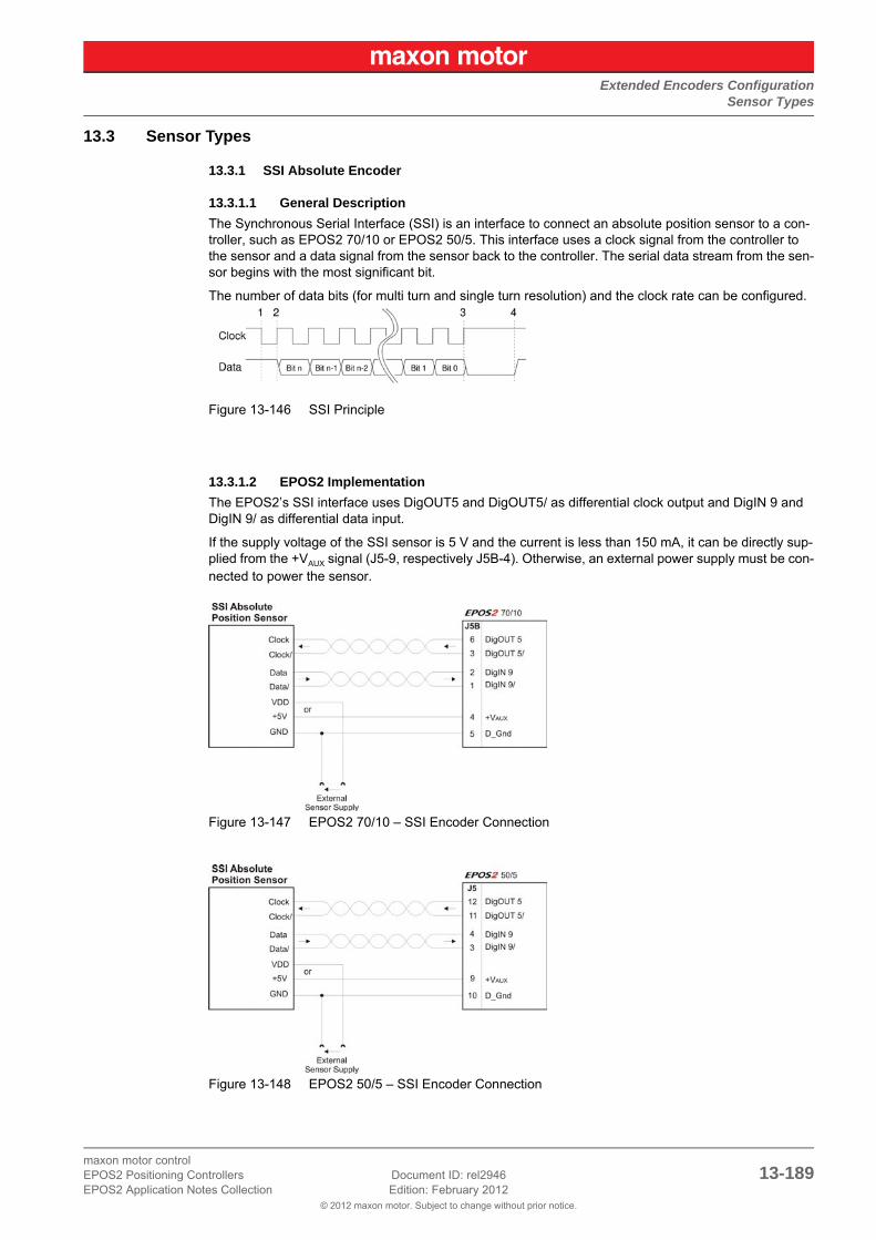
Extended Encoders ConfigurationSensor Types
© 2012 maxon motor. Subject to change without prior notice.
maxon motor controlEPOS2 Positioning Controllers Document ID: rel2946 13-189EPOS2 Application Notes Collection Edition: February 2012
13.3 Sensor Types
13.3.1 SSI Absolute Encoder
13.3.1.1 General Description
The Synchronous Serial Interface (SSI) is an interface to connect an absolute position sensor to a con-troller, such as EPOS2 70/10 or EPOS2 50/5. This interface uses a clock signal from the controller to the sensor and a data signal from the sensor back to the controller. The serial data stream from the sen-sor begins with the most significant bit.
The number of data bits (for multi turn and single turn resolution) and the clock rate can be configured.
Figure 13-146 SSI Principle
13.3.1.2 EPOS2 Implementation
The EPOS2’s SSI interface uses DigOUT5 and DigOUT5/ as differential clock output and DigIN 9 and DigIN 9/ as differential data input.
If the supply voltage of the SSI sensor is 5 V and the current is less than 150 mA, it can be directly sup-plied from the +VAUX signal (J5-9, respectively J5B-4). Otherwise, an external power supply must be con-nected to power the sensor.
Figure 13-147 EPOS2 70/10 – SSI Encoder Connection
Figure 13-148 EPOS2 50/5 – SSI Encoder Connection

Extended Encoders ConfigurationSensor Types
© 2012 maxon motor. Subject to change without prior notice.
maxon motor control13-190 Document ID: rel2946 EPOS2 Positioning Controllers
Edition: February 2012 EPOS2 Application Notes Collection
Figure 13-149 EPOS2 70/10 & EPOS2 50/5 – DigIN9 “Differential” Circuit
Figure 13-150 EPOS2 70/10 & EPOS2 50/5 – DigOUT5 “Differential” Circuit
Differential
DigIN9 “High Speed Command” Connector [J5B] Pins [1] / [2]
Min. differential input voltage ±200 mV
Line receiver (internal) EIA RS422 Standard
Max. input frequency 5 MHz
Differential
DigOUT5 “High Speed Output” Connector [J5B] Pins [3] / [6]
Differential output voltage min 1.5 V @ RL = 54 Ω
Output current max. 60 mA
Line transceiver (internal) EIA RS422 Standard
Max. output frequency 5 MHz

Extended Encoders ConfigurationSensor Types
© 2012 maxon motor. Subject to change without prior notice.
maxon motor controlEPOS2 Positioning Controllers Document ID: rel2946 13-191EPOS2 Application Notes Collection Edition: February 2012
13.3.1.3 Choice of Manufacturers for SSI Absolute Encoders
Table 13-183 SSI Absolute Encoder – Manufacturers (not concluding)
13.3.2 Incremental Encoder 2
13.3.2.1 General description
The incremental signals are transmitted as square-wave pulse trains A and B, phase-shifted by 90° electrical. The signals A and B and their inverted signals typically have TTL levels.
13.3.2.2 EPOS2 Implementation
A second incremental encoder can be connected to the EPOS2’s digital inputs DigIN7 to DigIN9, the same inputs which are used for «Master Encoder Mode» and «Step/Direction Mode». Therefore, this two modes cannot be used in conjunction with the Incremental Encoder 2.
If the supply voltage of the incremental encoder is 5 V and the current is less than 150 mA, it can be directly supplied from the +VAUX signal (J5-9, respectively J5B-4). Otherwise, an external power supply must be connected to power the sensor.
Figure 13-151 EPOS2 70/10 – Incremental Encoder 2 Connection
Manufacturer Contact
BaumerBaumer Electric AG, CH-8501 Frauenfeldwww.baumerelectric.com
HeidenhainDR. JOHANNES HEIDENHAIN GmbH, DE-83292 Traunreutwww.heidenhain.de
HengstlerHENGSTLER GmbH, DE-78554 Aldingenwww.hengstler.com
Posital FrabaPOSITAL GmbH, DE-51063 Colognewww.posital.de
and others

Extended Encoders ConfigurationSensor Types
© 2012 maxon motor. Subject to change without prior notice.
maxon motor control13-192 Document ID: rel2946 EPOS2 Positioning Controllers
Edition: February 2012 EPOS2 Application Notes Collection
Figure 13-152 EPOS2 50/5 – Incremental Encoder 2 Connection
Figure 13-153 EPOS2 70/10 & EPOS2 50/5 – DigIN7 “Differential” Circuit (analogously valid also for DigIN8)
Figure 13-154 EPOS2 Module 36/2 – Incremental Encoder 2 Connection
Differential
DigIN7 “High Speed Command”DigIN8 “High Speed Command”
Connector [J5A] Pins [9] / [10]Connector [J5A] Pins [11] / [12]
Min. differential input voltage ±200 mV
Line receiver (internal) EIA RS422 Standard
Max. input frequency 5 MHz

Extended Encoders ConfigurationSensor Types
© 2012 maxon motor. Subject to change without prior notice.
maxon motor controlEPOS2 Positioning Controllers Document ID: rel2946 13-193EPOS2 Application Notes Collection Edition: February 2012
Figure 13-155 EPOS2 Module 36/2 – DigIN7 “Differential” Circuit (analogously valid also for DigIN8)
13.3.2.3 Choice of Manufacturers for Incremental Encoder 2
Table 13-184 Incremental Encoder 2 – Manufacturers (not concluding)
Differential
DigIN7 “High Speed Command”DigIN8 “High Speed Command”
Pins [B18] / [B19]Pins [B20] / [B21]
Min. differential input voltage ±200 mV
Line receiver (internal) EIA RS422 Standard
Max. input frequency 5 MHz
Manufacturer Contact
maxonmaxon motor ag, CH-6072 Sachselnwww.maxonmotor.com
BaumerBaumer Electric AG, CH-8501 Frauenfeldwww.baumerelectric.com
HeidenhainDR. JOHANNES HEIDENHAIN GmbH, DE-83292 Traunreutwww.heidenhain.de
HengstlerHENGSTLER GmbH, DE-78554 Aldingenwww.hengstler.com
ScanconSCANCON A/S, DK-3450 Alleroedwww.scancon.dk
and others

Extended Encoders ConfigurationSensor Types
© 2012 maxon motor. Subject to change without prior notice.
maxon motor control13-194 Document ID: rel2946 EPOS2 Positioning Controllers
Edition: February 2012 EPOS2 Application Notes Collection
13.3.3 Sinus Incremental Encoder 2
13.3.3.1 General Description
The sinusoidal incremental signals A and B are phase-shifted by 90° electrical. The differential signal has an amplitude of typically 1 Vpp. The number of periods per turn can be configured.
Figure 13-156 Sinus Incremental Encoder Principle
13.3.3.2 EPOS2 Implementation
A sinus incremental encoder can be connected to the EPOS2’s digital inputs DigIN7 and DigIN8, the same inputs which are used for «Master Encoder Mode» and «Step/Direction Mode». Therefore, this two modes cannot be used in conjunction with the Sinus Incremental Encoder 2.
If the supply voltage of the SSI sensor is 5 V and the current is less than 150 mA, it can be directly sup-plied from the +VAUX signal (J5-9, respectively J5B-4). Otherwise, an external power supply must be con-nected to power the sensor.
Figure 13-157 EPOS2 70/10 – Sinus Incremental Encoder Connection
Figure 13-158 EPOS2 50/5 – Sinus Incremental Encoder Connection

Extended Encoders ConfigurationSensor Types
© 2012 maxon motor. Subject to change without prior notice.
maxon motor controlEPOS2 Positioning Controllers Document ID: rel2946 13-195EPOS2 Application Notes Collection Edition: February 2012
Figure 13-159 EPOS2 70/10 & EPOS2 50/5 – DigIN7/DigIN8 “Differential” Input Circuit of Sinus Incre-mental Encoder 2
13.3.3.3 Choice of Manufacturers for Sinus Incremental Encoder 2
Table 13-185 Sinus Incremental Encoder 2 – Manufacturers (not concluding)
Manufacturer Contact
BaumerBaumer Electric AG, CH-8501 Frauenfeldwww.baumerelectric.com
HeidenhainDR. JOHANNES HEIDENHAIN GmbH, DE-83292 Traunreutwww.heidenhain.de
HengstlerHENGSTLER GmbH, DE-78554 Aldingenwww.hengstler.com
and others
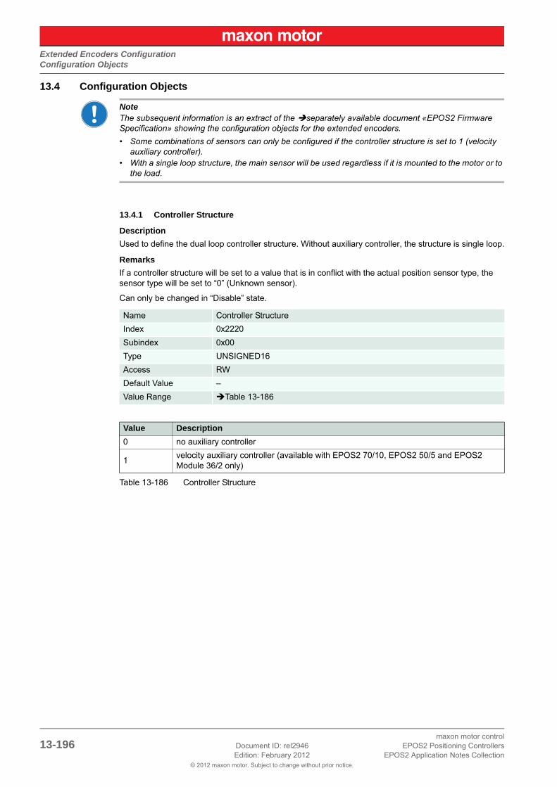
Extended Encoders ConfigurationConfiguration Objects
© 2012 maxon motor. Subject to change without prior notice.
maxon motor control13-196 Document ID: rel2946 EPOS2 Positioning Controllers
Edition: February 2012 EPOS2 Application Notes Collection
13.4 Configuration Objects
NoteThe subsequent information is an extract of the separately available document «EPOS2 Firmware Specification» showing the configuration objects for the extended encoders.
• Some combinations of sensors can only be configured if the controller structure is set to 1 (velocity auxiliary controller).
• With a single loop structure, the main sensor will be used regardless if it is mounted to the motor or to the load.
13.4.1 Controller Structure
Description
Used to define the dual loop controller structure. Without auxiliary controller, the structure is single loop.
Remarks
If a controller structure will be set to a value that is in conflict with the actual position sensor type, the sensor type will be set to “0” (Unknown sensor).
Can only be changed in “Disable” state.
Table 13-186 Controller Structure
Name Controller Structure
Index 0x2220
Subindex 0x00
Type UNSIGNED16
Access RW
Default Value –
Value Range Table 13-186
Value Description
0 no auxiliary controller
1velocity auxiliary controller (available with EPOS2 70/10, EPOS2 50/5 and EPOS2 Module 36/2 only)

Extended Encoders ConfigurationConfiguration Objects
© 2012 maxon motor. Subject to change without prior notice.
maxon motor controlEPOS2 Positioning Controllers Document ID: rel2946 13-197EPOS2 Application Notes Collection Edition: February 2012
13.4.2 Sensor Configuration
Description
Used to define the main and the auxiliary controller’s sensor type.
Figure 13-160 Regulation, Sensor and Gear Overview
Table 13-187 Position Sensor Type – Bits
Name Sensor Configuration
Index 0x2210
Number of entries 4
Name Position Sensor Type
Index 0x2210
Subindex 0x02
Type UNSIGNED16
Access RW
Default Value 0x01
Value Range Table 13-187 and Table 13-188
Bit Description
15…12 reserved (0)
11…8 Sensor type of auxiliary controller
7…4 reserved (0)
3…0 Sensor type of main controller
Value Description Abbreviation
0 Unknown sensor (undefined) –
1 Incremental Encoder 1 with index (3-channel)Inc Enc1
2 Incremental Encoder 1 without index (2-channel)
3 Hall Sensors (Remark: consider worse resolution) Hall
4 Absolute encoder SSI *1) SSI
5 reserved –
6 Incremental Encoder 2 with index (3-channel) *1) Inc Enc2
7 Incremental Encoder 2 without index (2-channel) *2)

Extended Encoders ConfigurationConfiguration Objects
© 2012 maxon motor. Subject to change without prior notice.
maxon motor control13-198 Document ID: rel2946 EPOS2 Positioning Controllers
Edition: February 2012 EPOS2 Application Notes Collection
Table 13-188 Supported Sensor Types
Description
Used to change the position sensor polarity.
Remarks
Can only be changed in “Disable” state.
The absolute position may be corrupted after changing this parameter.
Table 13-189 Position Sensor Polarity
8 Sinus Incremental Encoder 2 *1) Sin Inc Enc2
Remarks:*1) only available with EPOS2 70/10 and EPOS2 50/5*2) only available with EPOS2 70/10, EPOS2 50/5 and EPOS2 Module
Name Position Sensor Polarity
Index 0x2210
Subindex 0x04
Type UNSIGNED16
Access RW
Default Value 0x00
Value Range Table 13-189
Bit
Va
lue
Name Description
00 Incremental
Encoder 1
normal Enc1 polarity (CCW counts positive)
1 inverted Enc1 polarity (or encoder mounted on motor shaft)
10
Hall sensorsnormal Hall sensor polarity (maxon standard)
1 inverted Hall sensor polarity
20
SSI Encodernormal SSI polarity (CCW counts positive)
1 inverted SSI polarity
30 Incremental
Encoder 2 *2)
normal Enc2 polarity (CCW counts positive)
1 inverted Enc2 polarity (or encoder mounted on motor shaft)
40 Sinus
Incremental Encoder *1)
normal Enc2Sin Encoder polarity (CCW counts positive)
1 inverted Enc2Sin Encoder polarity
5…15 (0) reserved –
Remarks:*1) only available with EPOS2 70/10 and EPOS2 50/5*2) only available with EPOS2 70/10, EPOS2 50/5 and EPOS2 Module 36/2
Value Description Abbreviation

Extended Encoders ConfigurationConfiguration Objects
© 2012 maxon motor. Subject to change without prior notice.
maxon motor controlEPOS2 Positioning Controllers Document ID: rel2946 13-199EPOS2 Application Notes Collection Edition: February 2012
13.4.3 SSI Encoder Configuration
Description
Used to configure the interpretation of the SSI Encoder.
Remark
Changes are only supported in “Disable” state.
Description
SSI data rate (SSI clock frequency) in [kbit/s].
Remark
The maximal data rate depends on the actual line length and the employed SSI encoders’ specifica-tions. Typically are 400 kbit/s for cable lengths <50 m.
Description
Defines the number of multi-turn and single-turn bits. The maximal number of bits for both values com-bined is 32. The resolution is 2number of bits single-turn.
Table 13-190 SSI Encoder Number of Data Bits
Name SSI Encoder Configuration
Index 0x2211
Number of entries 4
Name SSI Encoder Datarate
Index 0x2211
Subindex 0x01
Type UNSIGNED16
Access RW
Default Value 500
Value Range 400 2 000
Name SSI Encoder Number of Data Bits
Index 0x2211
Subindex 0x02
Type UNSIGNED16
Access RW
Default Value 3085 (0x0C0D)
Value Range Table 13-190
Bit NameValue
Minimal Maximal Default
15…8 number of bits multi-turn 0 26 12
7…0 number of bits single-turn 6 23 13

Extended Encoders ConfigurationConfiguration Objects
© 2012 maxon motor. Subject to change without prior notice.
maxon motor control13-200 Document ID: rel2946 EPOS2 Positioning Controllers
Edition: February 2012 EPOS2 Application Notes Collection
Description
Position received from encoder [Position units] (page 1-12).
Description
Defines the SSI’s encoding type.
Table 13-191 SSI Encoding Type
Name SSI Encoder Actual Position
Index 0x2211
Subindex 0x03
Type INTEGER32
Access RO
Default Value –
Value Range – –
Name SSI Encoding Type
Index 0x2211
Subindex 0x04
Type UNSIGNED16
Access RW
Default Value 0
Value Range Table 13-191
Value Description
0 SSI Encoder binary type
1 SSI Encoder Gray coded

Extended Encoders ConfigurationConfiguration Objects
© 2012 maxon motor. Subject to change without prior notice.
maxon motor controlEPOS2 Positioning Controllers Document ID: rel2946 13-201EPOS2 Application Notes Collection Edition: February 2012
13.4.4 Incremental Encoder 2 Configuration
Description
Used to configure the interpretation of the Incremental Encoder 2.
Remarks
Can only be changed in “Disable” state.
The absolute position may be corrupted after changing this parameter.
Description
The encoder’s pulse number must be set to number of pulses per turn of the connected Incremental Encoder.
Description
Holds the internal counter register of the Incremental Encoder 2. It shows the actual encoder position in quad counts [qc].
Description
Holds the Incremental Encoder 2 counter reached upon last detected encoder index pulse. It shows the actual encoder index position in quad counts [qc].
Name Incremental Encoder 2 Configuration
Index 0x2212
Number of entries 3
Name Incremental Encoder 2 Pulse Number
Index 0x2212
Subindex 0x01
Type UNSIGNED32
Access RW
Default Value 500
Value Range 16 2 500 000
Name Incremental Encoder 2 Counter
Index 0x2212
Subindex 0x02
Type UNSIGNED32
Access RO
Default Value –
Value Range – –
Name Incremental Encoder 2 Counter at Index Pulse
Index 0x2212
Subindex 0x03
Type UNSIGNED32
Access RO
Default Value –
Value Range – –

Extended Encoders ConfigurationConfiguration Objects
© 2012 maxon motor. Subject to change without prior notice.
maxon motor control13-202 Document ID: rel2946 EPOS2 Positioning Controllers
Edition: February 2012 EPOS2 Application Notes Collection
13.4.5 Sinus Incremental Encoder 2 Configuration
Description
Used to configure the Sinus Incremental Encoder 2 Configuration’s interpretation.
Remarks
Can only be changed in “Disable” state.
The absolute position may be corrupted after changing this parameter.
Description
Defines the resolution of “Sinus Incremental Encoder 2”. The parameter pulses per turn must be set to the number of pulses per revolution of the connected Sinus Incremental Encoder.
This value multiplied by 2number of interpolation bits is the total resolution of the Sinus Incremental Encoder.
The values are further limited as follows:
Table 13-192 Encoder 2 Resolution
Description
Position received from Sinus Incremental Encoder [Position units] (page 1-12).
Name Sinus Incremental Encoder 2 Configuration
Index 0x2213
Number of entries 2
Max. resolution: 2number of interpolation bits * pulses per turn ≤ 10 000 000
Min. resolution: 2number of interpolation bits * pulses per turn ≥ 64
Name Sinus Incremental Encoder 2 Resolution
Index 0x2213
Subindex 0x01
Type UNSIGNED32
Access RW
Default Value 0x00800006
Value Range Table 13-192
Bit NameValue
Minimal Maximal Default
15…8 pulses per turn 1 2 500 000 2048
7…0 number of interpolation bits 2 10 4
Name Sinus Incremental Encoder 2 Actual Position
Index 0x2213
Subindex 0x02
Type INTEGER32
Access RO
Default Value –
Value Range – –

Extended Encoders ConfigurationApplication Examples
© 2012 maxon motor. Subject to change without prior notice.
maxon motor controlEPOS2 Positioning Controllers Document ID: rel2946 13-203EPOS2 Application Notes Collection Edition: February 2012
13.5 Application Examples
Best PracticeThe system should work correct if you employ components as listed and configure them as described.
If not the case, check the objects’ configuration after executing the described wizards and adjust/tune them according to the actual components employed.
13.5.1 Example 1: Single Loop DC Motor / Gear / SSI Absolute Encoder
Table 13-193 Example 1 – Setup
Figure 13-161 Example 1 – Wiring Diagram
1) Wire the system according to the wiring diagram (Figure 13-161).
2) Follow the configuration steps in the “Startup Wizard” of «EPOS Studio».
3) Upon successful configuration, start the “Regulation Tuning Wizard”.
4) Now your system is ready to use.For verification purposes: The related objects should have been set as follows:
Figure 13-162 Example 1 – Object Configuration
Equipment Type / Specifications
Controller maxon motor controller EPOS2 70/10 (375711)
Motor maxon DC motor (any)
Gearmaxon gear (any)reduction 23:1 (absolute 576:25), recommended input speed <6000 rpm
Absolute SSI Encoder
Baumer BMMH (42S105C 12/13 B25)Coding: GrayInterface Data Rate: 500 kbit/sSingleturn Data Bits: 12Multiturn Data Bits: 13

Extended Encoders ConfigurationApplication Examples
© 2012 maxon motor. Subject to change without prior notice.
maxon motor control13-204 Document ID: rel2946 EPOS2 Positioning Controllers
Edition: February 2012 EPOS2 Application Notes Collection
13.5.2 Example 2: Dual Loop Incremental Encoder (2 Ch) / EC Motor / Gear / Incremental Encoder (3 Ch)
Table 13-194 Example 2 – Setup
Figure 13-163 Example 2 – Wiring Diagram
Equipment Type / Specifications
Controller maxon motor controller EPOS2 50/5 (347717)
Motor maxon EC motor (any)
Auxiliary Encodermaxon Encoder MRCounts per turn: 1000 inc.Number of Channels: 2 (or 3)
Gearmaxon gear (any)reduction 5.8:1 (absolute 23:4), recommended input speed <8000 rpm
Main EncoderBaumer BHF (16.05A 7200-E2-5)Counts per turn: 7200 inc.Number of Channels: 3
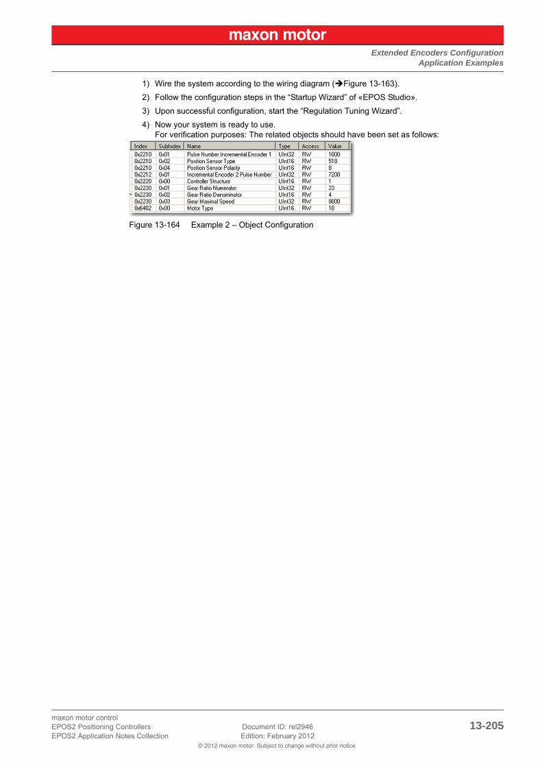
Extended Encoders ConfigurationApplication Examples
© 2012 maxon motor. Subject to change without prior notice.
maxon motor controlEPOS2 Positioning Controllers Document ID: rel2946 13-205EPOS2 Application Notes Collection Edition: February 2012
1) Wire the system according to the wiring diagram (Figure 13-163).
2) Follow the configuration steps in the “Startup Wizard” of «EPOS Studio».
3) Upon successful configuration, start the “Regulation Tuning Wizard”.
4) Now your system is ready to use.For verification purposes: The related objects should have been set as follows:
Figure 13-164 Example 2 – Object Configuration

Extended Encoders ConfigurationApplication Examples
© 2012 maxon motor. Subject to change without prior notice.
maxon motor control13-206 Document ID: rel2946 EPOS2 Positioning Controllers
Edition: February 2012 EPOS2 Application Notes Collection
• • p a g e i n t e n t i o n a l l y l e f t b l a n k • •

maxon motor controlEPOS2 Positioning Controllers Document ID: rel2946 Z-207EPOS2 Application Notes Collection Edition: February 2012
© 2012 maxon motor. Subject to change without prior notice.
Figure 2-1 Digital Input Functionality – EPOS2 50/5 Overview (default Configuration) . . . . . . . . .14
Figure 2-2 Digital Output Functionality – EPOS2 Overview (default Configuration) . . . . . . . . . . .17
Figure 2-3 EPOS Signal Cable 1 . . . . . . . . . . . . . . . . . . . . . . . . . . . . . . . . . . . . . . . . . . . . . . . . . .19
Figure 2-4 EPOS Signal Cable 2 . . . . . . . . . . . . . . . . . . . . . . . . . . . . . . . . . . . . . . . . . . . . . . . . . .21
Figure 2-5 EPOS2 Signal Cable 4 . . . . . . . . . . . . . . . . . . . . . . . . . . . . . . . . . . . . . . . . . . . . . . . . .23
Figure 2-6 EPOS Signal Cable 1 . . . . . . . . . . . . . . . . . . . . . . . . . . . . . . . . . . . . . . . . . . . . . . . . . .24
Figure 2-7 EPOS Signal Cable 2 . . . . . . . . . . . . . . . . . . . . . . . . . . . . . . . . . . . . . . . . . . . . . . . . . .26
Figure 2-8 EPOS2 Module 36/2 – PCB with Connector Array. . . . . . . . . . . . . . . . . . . . . . . . . . . .28
Figure 2-9 EPOS Signal Cable 1 . . . . . . . . . . . . . . . . . . . . . . . . . . . . . . . . . . . . . . . . . . . . . . . . . .29
Figure 2-10 Connector J1 . . . . . . . . . . . . . . . . . . . . . . . . . . . . . . . . . . . . . . . . . . . . . . . . . . . . . . . .31
Figure 2-11 Open I/O Configuration Wizard . . . . . . . . . . . . . . . . . . . . . . . . . . . . . . . . . . . . . . . . . .32
Figure 2-12 Configuration Wizard – Introduction . . . . . . . . . . . . . . . . . . . . . . . . . . . . . . . . . . . . . . .32
Figure 2-13 Configuration Wizard – Configure Digital Inputs. . . . . . . . . . . . . . . . . . . . . . . . . . . . . .32
Figure 2-14 Configuration Wizard – Configure Digital Input Functionality . . . . . . . . . . . . . . . . . . . .33
Figure 2-15 Configuration Wizard – Configure Digital Outputs . . . . . . . . . . . . . . . . . . . . . . . . . . . .33
Figure 2-16 Safe Configuration . . . . . . . . . . . . . . . . . . . . . . . . . . . . . . . . . . . . . . . . . . . . . . . . . . . .33
Figure 2-17 EPOS2 70/10 – DigIN4…6 / Proximity Switches . . . . . . . . . . . . . . . . . . . . . . . . . . . . .34
Figure 2-18 EPOS2 70/10 – DigOUT4 / permanent Magnet Brake . . . . . . . . . . . . . . . . . . . . . . . . .35
Figure 2-19 EPOS2 50/5 – DigIN4…6 / PNP/NPN Proximity Switches . . . . . . . . . . . . . . . . . . . . . .35
Figure 2-20 EPOS2 50/5 – DigOUT4 / permanent Magnet Brake . . . . . . . . . . . . . . . . . . . . . . . . . .36
Figure 2-21 EPOS2 Module 36/2 – DigIN4 / PNP Proximity Switch (applies also for DigIN2/3) . . .36
Figure 2-22 EPOS2 Module 36/2 – DigIN4 / Photoelectric Sensor (applies also for DigIN2/3) . . . .36
Figure 2-23 EPOS2 Module 36/2 – DigOUT1 “sink” (applies also for DigIN2). . . . . . . . . . . . . . . . .37
Figure 2-24 EPOS2 Module 36/2 – DigOUT1 “source” (applies also for DigIN2) . . . . . . . . . . . . . .37
Figure 2-25 EPOS2 24/5 – DigIN4 / PNP Proximity Switch (applies also for DigIN5/6) . . . . . . . . .38
Figure 2-26 EPOS2 24/5 – DigIN4 / NPN Proximity Switch (applies also for DigIN5/6) . . . . . . . . .38
Figure 2-27 EPOS2 24/5 – DigOUT1 “sink” . . . . . . . . . . . . . . . . . . . . . . . . . . . . . . . . . . . . . . . . . . .39
Figure 2-28 EPOS2 24/5 – DigOUT1 “source”. . . . . . . . . . . . . . . . . . . . . . . . . . . . . . . . . . . . . . . . .39
Figure 2-29 EPOS2 24/2 – DigIN4 / PNP Proximity Switch (applies also for DigIN5/6) . . . . . . . . .40
Figure 2-30 EPOS2 24/2 – DigIN4 / Photoelectric Sensor (analogously valid also for DigIN5/6) . .40
Figure 3-31 Analog Input Functionality – EPOS2 Overview (default Configuration) . . . . . . . . . . . .42
Figure 3-32 Analog Output Functionality – EPOS2 Overview (default Configuration) . . . . . . . . . . .44
Figure 3-33 EPOS Signal Cable 2 . . . . . . . . . . . . . . . . . . . . . . . . . . . . . . . . . . . . . . . . . . . . . . . . . .45
Figure 3-34 EPOS2 Signal Cable 3 . . . . . . . . . . . . . . . . . . . . . . . . . . . . . . . . . . . . . . . . . . . . . . . . .47
Figure 3-35 EPOS2 Module 36/2 – PCB with Connector Array. . . . . . . . . . . . . . . . . . . . . . . . . . . .48
Figure 3-36 EPOS Signal Cable 1 . . . . . . . . . . . . . . . . . . . . . . . . . . . . . . . . . . . . . . . . . . . . . . . . . .49
Figure 3-37 Open I/O Configuration Wizard . . . . . . . . . . . . . . . . . . . . . . . . . . . . . . . . . . . . . . . . . .52
Figure 3-38 Configuration Wizard – Introduction . . . . . . . . . . . . . . . . . . . . . . . . . . . . . . . . . . . . . . .52
Figure 3-39 Configuration Wizard – Configure Analog Inputs . . . . . . . . . . . . . . . . . . . . . . . . . . . . .52
Figure 3-40 Configuration Wizard – Configure Analog Input Functionality . . . . . . . . . . . . . . . . . . .53
Figure 3-41 Safe Configuration . . . . . . . . . . . . . . . . . . . . . . . . . . . . . . . . . . . . . . . . . . . . . . . . . . . .53
Figure 4-42 Master Encoder Mode – System Structure. . . . . . . . . . . . . . . . . . . . . . . . . . . . . . . . . .56
LIST OF FIGURES

maxon motor controlZ-208 Document ID: rel2946 EPOS2 Positioning Controllers
Edition: February 2012 EPOS2 Application Notes Collection© 2012 maxon motor. Subject to change without prior notice.
Figure 4-43 Startup Wizard . . . . . . . . . . . . . . . . . . . . . . . . . . . . . . . . . . . . . . . . . . . . . . . . . . . . . . . 58
Figure 4-44 Regulation Tuning . . . . . . . . . . . . . . . . . . . . . . . . . . . . . . . . . . . . . . . . . . . . . . . . . . . . 58
Figure 4-45 Configuration Wizard . . . . . . . . . . . . . . . . . . . . . . . . . . . . . . . . . . . . . . . . . . . . . . . . . . 59
Figure 4-46 Master Encoder Mode – Configuration. . . . . . . . . . . . . . . . . . . . . . . . . . . . . . . . . . . . . 59
Figure 4-47 Master Encoder Mode – Application Example: Dual Axes System . . . . . . . . . . . . . . . 60
Figure 5-48 Step/Direction Mode – System Structure . . . . . . . . . . . . . . . . . . . . . . . . . . . . . . . . . . . 64
Figure 5-49 Startup Wizard . . . . . . . . . . . . . . . . . . . . . . . . . . . . . . . . . . . . . . . . . . . . . . . . . . . . . . . 66
Figure 5-50 Regulation Tuning . . . . . . . . . . . . . . . . . . . . . . . . . . . . . . . . . . . . . . . . . . . . . . . . . . . . 66
Figure 5-51 Configuration Wizard . . . . . . . . . . . . . . . . . . . . . . . . . . . . . . . . . . . . . . . . . . . . . . . . . . 67
Figure 5-52 Step/Direction Mode – Configuration . . . . . . . . . . . . . . . . . . . . . . . . . . . . . . . . . . . . . . 67
Figure 5-53 Step/Direction Mode – Application Example: Slave Axis System . . . . . . . . . . . . . . . . 68
Figure 6-54 Interpolated Position Mode – PVT Principle. . . . . . . . . . . . . . . . . . . . . . . . . . . . . . . . . 73
Figure 6-55 Interpolated Position Mode – Clock Synchronization . . . . . . . . . . . . . . . . . . . . . . . . . . 74
Figure 6-56 Interpolated Position Mode – Interpolation Controller . . . . . . . . . . . . . . . . . . . . . . . . . 75
Figure 6-57 Interpolated Position Mode – FIFO Organization . . . . . . . . . . . . . . . . . . . . . . . . . . . . . 76
Figure 6-58 Interpolated Position Mode – FSA . . . . . . . . . . . . . . . . . . . . . . . . . . . . . . . . . . . . . . . . 76
Figure 6-59 CANopen Wizard #5. . . . . . . . . . . . . . . . . . . . . . . . . . . . . . . . . . . . . . . . . . . . . . . . . . . 87
Figure 6-60 Change Mapping Receive PDO1 . . . . . . . . . . . . . . . . . . . . . . . . . . . . . . . . . . . . . . . . . 87
Figure 6-61 CANopen Wizard #13. . . . . . . . . . . . . . . . . . . . . . . . . . . . . . . . . . . . . . . . . . . . . . . . . . 88
Figure 6-62 Change Mapping Transmit PDO1 . . . . . . . . . . . . . . . . . . . . . . . . . . . . . . . . . . . . . . . . 88
Figure 7-63 Regulation Tuning – Current Control . . . . . . . . . . . . . . . . . . . . . . . . . . . . . . . . . . . . . . 92
Figure 7-64 Regulation Tuning – Velocity Control . . . . . . . . . . . . . . . . . . . . . . . . . . . . . . . . . . . . . . 92
Figure 7-65 Regulation Tuning – Position Control. . . . . . . . . . . . . . . . . . . . . . . . . . . . . . . . . . . . . . 93
Figure 7-66 Regulation Tuning Wizard . . . . . . . . . . . . . . . . . . . . . . . . . . . . . . . . . . . . . . . . . . . . . . 94
Figure 7-67 Regulation Tuning Mode Selection . . . . . . . . . . . . . . . . . . . . . . . . . . . . . . . . . . . . . . . 94
Figure 7-68 Expert Tuning – Cascade. . . . . . . . . . . . . . . . . . . . . . . . . . . . . . . . . . . . . . . . . . . . . . .95
Figure 7-69 Expert Tuning – Identification. . . . . . . . . . . . . . . . . . . . . . . . . . . . . . . . . . . . . . . . . . . . 96
Figure 7-70 Expert Tuning – Parameterization . . . . . . . . . . . . . . . . . . . . . . . . . . . . . . . . . . . . . . . . 96
Figure 7-71 Expert Tuning – Verification . . . . . . . . . . . . . . . . . . . . . . . . . . . . . . . . . . . . . . . . . . . . . 96
Figure 9-72 Controller Architecture . . . . . . . . . . . . . . . . . . . . . . . . . . . . . . . . . . . . . . . . . . . . . . . . 116
Figure 9-73 Controller Architecture – Current Regulator . . . . . . . . . . . . . . . . . . . . . . . . . . . . . . . . 117
Figure 9-74 Controller Architecture – Velocity Regulator . . . . . . . . . . . . . . . . . . . . . . . . . . . . . . . 118
Figure 9-75 Controller Architecture – Position Regulator with Feedforward . . . . . . . . . . . . . . . . . 119
Figure 9-76 Dual Loop Architecture. . . . . . . . . . . . . . . . . . . . . . . . . . . . . . . . . . . . . . . . . . . . . . . . 121
Figure 9-77 Dual Loop Velocity Regulation . . . . . . . . . . . . . . . . . . . . . . . . . . . . . . . . . . . . . . . . . . 122
Figure 9-78 Dual Loop Position Regulation . . . . . . . . . . . . . . . . . . . . . . . . . . . . . . . . . . . . . . . . . . 122
Figure 9-79 Example1 – Block Diagram . . . . . . . . . . . . . . . . . . . . . . . . . . . . . . . . . . . . . . . . . . . . 124
Figure 9-80 Example1 – System Parameters, real . . . . . . . . . . . . . . . . . . . . . . . . . . . . . . . . . . . . 125
Figure 9-81 Example1 – Current Regulation, Block Model . . . . . . . . . . . . . . . . . . . . . . . . . . . . . . 127
Figure 9-82 Example1 – Current Regulation, simulated . . . . . . . . . . . . . . . . . . . . . . . . . . . . . . . . 127
Figure 9-83 Example1 – Current Regulation, measured . . . . . . . . . . . . . . . . . . . . . . . . . . . . . . . . 127
Figure 9-84 Example1 – Velocity Regulation, Block Model . . . . . . . . . . . . . . . . . . . . . . . . . . . . . . 128
Figure 9-85 Example1 – Velocity Regulation, simulated . . . . . . . . . . . . . . . . . . . . . . . . . . . . . . . . 128
Figure 9-86 Example1 – Velocity Regulation, measured. . . . . . . . . . . . . . . . . . . . . . . . . . . . . . . . 128
Figure 9-87 Example1 – Position Control with Feedforward, Block Model . . . . . . . . . . . . . . . . . . 129

maxon motor controlEPOS2 Positioning Controllers Document ID: rel2946 Z-209EPOS2 Application Notes Collection Edition: February 2012
© 2012 maxon motor. Subject to change without prior notice.
Figure 9-88 Example1 – Position Control with Feedforward, simulated . . . . . . . . . . . . . . . . . . . .129
Figure 9-89 Example1 – Position Control with Feedforward, measured . . . . . . . . . . . . . . . . . . . .129
Figure 9-90 Example1 – Position Control without Feedforward, simulated . . . . . . . . . . . . . . . . . .130
Figure 9-91 Example1 – Position Control without Feedforward, measured. . . . . . . . . . . . . . . . . .130
Figure 9-92 Example1 – Position Control with incorrect Feedforward, simulated . . . . . . . . . . . . .131
Figure 9-93 Example1 – Position Control with incorrect Feedforward, measured. . . . . . . . . . . . .131
Figure 9-94 Controller Architecture – Example 2: System with low Inertia/high Friction . . . . . . . .132
Figure 9-95 Example 2 – Block Diagram . . . . . . . . . . . . . . . . . . . . . . . . . . . . . . . . . . . . . . . . . . . .132
Figure 9-96 Example 2 – System Parameters, real . . . . . . . . . . . . . . . . . . . . . . . . . . . . . . . . . . . .133
Figure 9-97 Example 2 – Current Regulation, Block Model . . . . . . . . . . . . . . . . . . . . . . . . . . . . . .135
Figure 9-98 Example 2 – Current Regulation, simulated . . . . . . . . . . . . . . . . . . . . . . . . . . . . . . . .135
Figure 9-99 Example 2 – Current Regulation, measured. . . . . . . . . . . . . . . . . . . . . . . . . . . . . . . .135
Figure 9-100 Example 2 – Velocity Regulation, Block Model . . . . . . . . . . . . . . . . . . . . . . . . . . . . .136
Figure 9-101 Example 2 – Velocity Regulation, simulated. . . . . . . . . . . . . . . . . . . . . . . . . . . . . . . .136
Figure 9-102 Example 2 – Velocity Regulation, measured . . . . . . . . . . . . . . . . . . . . . . . . . . . . . . .136
Figure 9-103 Example 2 – Position Control with Feedforward, Block Model . . . . . . . . . . . . . . . . . .137
Figure 9-104 Example 2 – Position Control with Feedforward, simulated . . . . . . . . . . . . . . . . . . . .137
Figure 9-105 Example 2 – Position Control with Feedforward, measured. . . . . . . . . . . . . . . . . . . .137
Figure 9-106 Example 2 – Position Control without Feedforward, simulated . . . . . . . . . . . . . . . . .138
Figure 9-107 Example 2 – Position Control without Feedforward, measured . . . . . . . . . . . . . . . . .138
Figure 10-108 CANopen Network Structure (Example) . . . . . . . . . . . . . . . . . . . . . . . . . . . . . . . . . . .141
Figure 10-109 EPOS2 70/10 – DIP Switch . . . . . . . . . . . . . . . . . . . . . . . . . . . . . . . . . . . . . . . . . . . .141
Figure 10-110 EPOS2 50/5 – DIP Switch . . . . . . . . . . . . . . . . . . . . . . . . . . . . . . . . . . . . . . . . . . . . .141
Figure 10-111 EPOS2 24/5 – DIP Switch . . . . . . . . . . . . . . . . . . . . . . . . . . . . . . . . . . . . . . . . . . . . .141
Figure 10-112 EPOS2 24/2 – DIP Switch . . . . . . . . . . . . . . . . . . . . . . . . . . . . . . . . . . . . . . . . . . . . .141
Figure 10-113 CAN Connector Types . . . . . . . . . . . . . . . . . . . . . . . . . . . . . . . . . . . . . . . . . . . . . . . .143
Figure 10-114 Connector Array . . . . . . . . . . . . . . . . . . . . . . . . . . . . . . . . . . . . . . . . . . . . . . . . . . . . .143
Figure 10-115 D-Sub Connector . . . . . . . . . . . . . . . . . . . . . . . . . . . . . . . . . . . . . . . . . . . . . . . . . . . .143
Figure 10-116 RJ45 Connector . . . . . . . . . . . . . . . . . . . . . . . . . . . . . . . . . . . . . . . . . . . . . . . . . . . . .143
Figure 10-117 DIP Switch EPOS2 70/10 & DIP Switch EPOS2 24/5 . . . . . . . . . . . . . . . . . . . . . . . .144
Figure 10-118 DIP Switch EPOS2 50/5 . . . . . . . . . . . . . . . . . . . . . . . . . . . . . . . . . . . . . . . . . . . . . . .144
Figure 10-119 DIP Switch EPOS2 24/2 . . . . . . . . . . . . . . . . . . . . . . . . . . . . . . . . . . . . . . . . . . . . . . .145
Figure 10-120 Example: Boot Up Message of Node 1 . . . . . . . . . . . . . . . . . . . . . . . . . . . . . . . . . . .147
Figure 10-121 SDO Communication . . . . . . . . . . . . . . . . . . . . . . . . . . . . . . . . . . . . . . . . . . . . . . . . .148
Figure 10-122 SDO Upload Protocol (Expedited Transfer) – Read. . . . . . . . . . . . . . . . . . . . . . . . . .148
Figure 10-123 SDO Upload Protocol (Expedited Transfer) – Write . . . . . . . . . . . . . . . . . . . . . . . . . .148
Figure 10-124 SDO Upload Protocol (Expedited Transfer) – Abort . . . . . . . . . . . . . . . . . . . . . . . . . .149
Figure 10-125 Network Management (NMT) . . . . . . . . . . . . . . . . . . . . . . . . . . . . . . . . . . . . . . . . . . .151
Figure 10-126 NMT Slave State Diagram . . . . . . . . . . . . . . . . . . . . . . . . . . . . . . . . . . . . . . . . . . . . .151
Figure 10-127 PDO Mapping . . . . . . . . . . . . . . . . . . . . . . . . . . . . . . . . . . . . . . . . . . . . . . . . . . . . . . .152
Figure 10-128 Node Guarding Protocol – Timing Diagram . . . . . . . . . . . . . . . . . . . . . . . . . . . . . . . .155
Figure 10-129 Heartbeat Protocol – Timing Diagram . . . . . . . . . . . . . . . . . . . . . . . . . . . . . . . . . . . .157
Figure 11-130 Gateway Communication Structure . . . . . . . . . . . . . . . . . . . . . . . . . . . . . . . . . . . . . .160
Figure 11-131 Communication via USB (Example) . . . . . . . . . . . . . . . . . . . . . . . . . . . . . . . . . . . . . .161
Figure 11-132 Communication via RS232 (Example) . . . . . . . . . . . . . . . . . . . . . . . . . . . . . . . . . . . .163

maxon motor controlZ-210 Document ID: rel2946 EPOS2 Positioning Controllers
Edition: February 2012 EPOS2 Application Notes Collection© 2012 maxon motor. Subject to change without prior notice.
Figure 12-133 Data Recorder Overview . . . . . . . . . . . . . . . . . . . . . . . . . . . . . . . . . . . . . . . . . . . . . . 170
Figure 12-134 Data Recording – “Configure Recorder” Dialog . . . . . . . . . . . . . . . . . . . . . . . . . . . . . 173
Figure 12-135 Configure Data Recorder . . . . . . . . . . . . . . . . . . . . . . . . . . . . . . . . . . . . . . . . . . . . . . 174
Figure 12-136 Select Configuration Options . . . . . . . . . . . . . . . . . . . . . . . . . . . . . . . . . . . . . . . . . . .175
Figure 12-137 Execute Movement. . . . . . . . . . . . . . . . . . . . . . . . . . . . . . . . . . . . . . . . . . . . . . . . . . . 175
Figure 12-138 Save recorded Data . . . . . . . . . . . . . . . . . . . . . . . . . . . . . . . . . . . . . . . . . . . . . . . . . . 175
Figure 12-139 Save recorded Data . . . . . . . . . . . . . . . . . . . . . . . . . . . . . . . . . . . . . . . . . . . . . . . . . . 176
Figure 12-140 Analyze recorded Data. . . . . . . . . . . . . . . . . . . . . . . . . . . . . . . . . . . . . . . . . . . . . . . . 176
Figure 12-141 Restart Data Recorder . . . . . . . . . . . . . . . . . . . . . . . . . . . . . . . . . . . . . . . . . . . . . . . . 177
Figure 12-142 Data Recorder Data Buffer – Segmentation. . . . . . . . . . . . . . . . . . . . . . . . . . . . . . . . 183
Figure 13-143 EPOS2 70/10 – Signal 2 Connector (J5A) . . . . . . . . . . . . . . . . . . . . . . . . . . . . . . . . . 186
Figure 13-144 EPOS2 70/10 – Signal 3 Connector (J5B) . . . . . . . . . . . . . . . . . . . . . . . . . . . . . . . . . 187
Figure 13-145 EPOS2 50/5 – Signal 1 Connector (J5) . . . . . . . . . . . . . . . . . . . . . . . . . . . . . . . . . . . 187
Figure 13-146 SSI Principle. . . . . . . . . . . . . . . . . . . . . . . . . . . . . . . . . . . . . . . . . . . . . . . . . . . . . . . . 189
Figure 13-147 EPOS2 70/10 – SSI Encoder Connection . . . . . . . . . . . . . . . . . . . . . . . . . . . . . . . . . 189
Figure 13-148 EPOS2 50/5 – SSI Encoder Connection . . . . . . . . . . . . . . . . . . . . . . . . . . . . . . . . . . 189
Figure 13-149 EPOS2 70/10 & EPOS2 50/5 – DigIN9 “Differential” Circuit . . . . . . . . . . . . . . . . . . . 190
Figure 13-150 EPOS2 70/10 & EPOS2 50/5 – DigOUT5 “Differential” Circuit . . . . . . . . . . . . . . . . . 190
Figure 13-151 EPOS2 70/10 – Incremental Encoder 2 Connection . . . . . . . . . . . . . . . . . . . . . . . . . 191
Figure 13-152 EPOS2 50/5 – Incremental Encoder 2 Connection . . . . . . . . . . . . . . . . . . . . . . . . . . 192
Figure 13-153 EPOS2 70/10 & EPOS2 50/5 – DigIN7 “Differential” Circuit (analogously valid also for DigIN8) . . . . . . . . . . . . . . . . . . . . . . . . . . . . . . . . . . . . . . . . . . . . . . . . . 192
Figure 13-154 EPOS2 Module 36/2 – Incremental Encoder 2 Connection . . . . . . . . . . . . . . . . . . . . 192
Figure 13-155 EPOS2 Module 36/2 – DigIN7 “Differential” Circuit (analogously valid also for DigIN8) . . . . . . . . . . . . . . . . . . . . . . . . . . . . . . . . . . . . . . . . . . . . . . . . . . . . . . . . . 193
Figure 13-156 Sinus Incremental Encoder Principle . . . . . . . . . . . . . . . . . . . . . . . . . . . . . . . . . . . . . 194
Figure 13-157 EPOS2 70/10 – Sinus Incremental Encoder Connection . . . . . . . . . . . . . . . . . . . . . . 194
Figure 13-158 EPOS2 50/5 – Sinus Incremental Encoder Connection . . . . . . . . . . . . . . . . . . . . . . . 194
Figure 13-159 EPOS2 70/10 & EPOS2 50/5 – DigIN7/DigIN8 “Differential” Input Circuit of Sinus Incremental Encoder 2 . . . . . . . . . . . . . . . . . . . . . . . . . . . . . . . . . . . . . . . . . . . 195
Figure 13-160 Regulation, Sensor and Gear Overview. . . . . . . . . . . . . . . . . . . . . . . . . . . . . . . . . . . 197
Figure 13-161 Example 1 – Wiring Diagram . . . . . . . . . . . . . . . . . . . . . . . . . . . . . . . . . . . . . . . . . . . 203
Figure 13-162 Example 1 – Object Configuration . . . . . . . . . . . . . . . . . . . . . . . . . . . . . . . . . . . . . . . 203
Figure 13-163 Example 2 – Wiring Diagram . . . . . . . . . . . . . . . . . . . . . . . . . . . . . . . . . . . . . . . . . . . 204
Figure 13-164 Example 2 – Object Configuration . . . . . . . . . . . . . . . . . . . . . . . . . . . . . . . . . . . . . . . 205

maxon motor controlEPOS2 Positioning Controllers Document ID: rel2946 Z-211EPOS2 Application Notes Collection Edition: February 2012
© 2012 maxon motor. Subject to change without prior notice.
Table 1-1 Notations used in this Document . . . . . . . . . . . . . . . . . . . . . . . . . . . . . . . . . . . . . . . . . .9
Table 1-2 Brand Names and Trademark Owners . . . . . . . . . . . . . . . . . . . . . . . . . . . . . . . . . . . . .11
Table 1-3 Sources for additional Information . . . . . . . . . . . . . . . . . . . . . . . . . . . . . . . . . . . . . . . .11
Table 1-4 Default Unit Dimensions . . . . . . . . . . . . . . . . . . . . . . . . . . . . . . . . . . . . . . . . . . . . . . . .12
Table 2-5 Digital Inputs & Outputs – covered Hardware and required Documents . . . . . . . . . . .13
Table 2-6 Digital Inputs & Outputs – recommended Tools . . . . . . . . . . . . . . . . . . . . . . . . . . . . . .13
Table 2-7 Digital Input – Configuration Parameter . . . . . . . . . . . . . . . . . . . . . . . . . . . . . . . . . . . .15
Table 2-8 Digital Input – Input Parameter . . . . . . . . . . . . . . . . . . . . . . . . . . . . . . . . . . . . . . . . . . .15
Table 2-9 Digital Input – Input Configuration Values . . . . . . . . . . . . . . . . . . . . . . . . . . . . . . . . . .16
Table 2-10 Digital Input – Execution Mask Parameter . . . . . . . . . . . . . . . . . . . . . . . . . . . . . . . . . .16
Table 2-11 Digital Input – Polarity Values. . . . . . . . . . . . . . . . . . . . . . . . . . . . . . . . . . . . . . . . . . . .16
Table 2-12 Digital Output – Configuration Parameter. . . . . . . . . . . . . . . . . . . . . . . . . . . . . . . . . . .17
Table 2-13 Digital Output – Output Configuration Values. . . . . . . . . . . . . . . . . . . . . . . . . . . . . . . .18
Table 2-14 Digital Output – Execution Mask Parameter. . . . . . . . . . . . . . . . . . . . . . . . . . . . . . . . .18
Table 2-15 Digital Output – Polarity Values . . . . . . . . . . . . . . . . . . . . . . . . . . . . . . . . . . . . . . . . . .18
Table 2-16 EPOS Signal Cable 1 – Technical Data . . . . . . . . . . . . . . . . . . . . . . . . . . . . . . . . . . . .19
Table 2-17 EPOS Signal Cable 1 – Pin Assignment EPOS2 70/10 . . . . . . . . . . . . . . . . . . . . . . . .20
Table 2-18 EPOS Signal Cable 2 – Technical Data . . . . . . . . . . . . . . . . . . . . . . . . . . . . . . . . . . . .21
Table 2-19 EPOS2 Signal Cable 2 – Pin Assignment EPOS2 70/10 . . . . . . . . . . . . . . . . . . . . . . .22
Table 2-20 EPOS2 Signal Cable 4 – Technical Data . . . . . . . . . . . . . . . . . . . . . . . . . . . . . . . . . . .23
Table 2-21 EPOS2 Signal Cable 4 – Pin Assignment EPOS2 70/10 . . . . . . . . . . . . . . . . . . . . . . .23
Table 2-22 EPOS Signal Cable 1 – Technical Data . . . . . . . . . . . . . . . . . . . . . . . . . . . . . . . . . . . .24
Table 2-23 EPOS Signal Cable 1 – Pin Assignment EPOS2 50/5 . . . . . . . . . . . . . . . . . . . . . . . . .25
Table 2-24 EPOS Signal Cable 2 – Technical Data . . . . . . . . . . . . . . . . . . . . . . . . . . . . . . . . . . . .26
Table 2-25 EPOS2 Signal Cable 3 – Pin Assignment EPOS2 50/5 . . . . . . . . . . . . . . . . . . . . . . . .27
Table 2-26 EPOS2 Module 36/2 – PCB Connectors . . . . . . . . . . . . . . . . . . . . . . . . . . . . . . . . . . .28
Table 2-27 EPOS2 Module 36/2 – Pin Assignment . . . . . . . . . . . . . . . . . . . . . . . . . . . . . . . . . . . .28
Table 2-28 EPOS Signal Cable 1 – Technical Data . . . . . . . . . . . . . . . . . . . . . . . . . . . . . . . . . . . .29
Table 2-29 EPOS Signal Cable 1 – Pin Assignment EPOS2 24/5 . . . . . . . . . . . . . . . . . . . . . . . . .30
Table 2-30 Connector J1 – Pin Assignment EPOS2 24/2 . . . . . . . . . . . . . . . . . . . . . . . . . . . . . . .31
Table 3-31 Analog Inputs & Outputs – covered Hardware and required Documents . . . . . . . . . . .41
Table 3-32 Analog Inputs & Outputs – recommended Tools . . . . . . . . . . . . . . . . . . . . . . . . . . . . .41
Table 3-33 Analog Input – Configuration Parameter . . . . . . . . . . . . . . . . . . . . . . . . . . . . . . . . . . .42
Table 3-34 Analog Input – Input Parameter . . . . . . . . . . . . . . . . . . . . . . . . . . . . . . . . . . . . . . . . . .42
Table 3-35 Analog Input – Input Configuration Values . . . . . . . . . . . . . . . . . . . . . . . . . . . . . . . . . .43
Table 3-36 Analog Input – Execution Mask Parameter . . . . . . . . . . . . . . . . . . . . . . . . . . . . . . . . .43
Table 3-37 Analog Output – Output Parameter . . . . . . . . . . . . . . . . . . . . . . . . . . . . . . . . . . . . . . .44
Table 3-38 EPOS Signal Cable 2 – Technical Data . . . . . . . . . . . . . . . . . . . . . . . . . . . . . . . . . . . .45
Table 3-39 EPOS2 Signal Cable 2 – Pin Assignment EPOS2 70/10 . . . . . . . . . . . . . . . . . . . . . . .46
Table 3-40 EPOS2 Signal Cable 3 – Technical Data . . . . . . . . . . . . . . . . . . . . . . . . . . . . . . . . . . .47
Table 3-41 EPOS2 Signal Cable 3 – Pin Assignment EPOS2 50/5 . . . . . . . . . . . . . . . . . . . . . . . .47
Table 3-42 EPOS2 Module 36/2 – PCB Connectors . . . . . . . . . . . . . . . . . . . . . . . . . . . . . . . . . . .48
LIST OF TABLES

maxon motor controlZ-212 Document ID: rel2946 EPOS2 Positioning Controllers
Edition: February 2012 EPOS2 Application Notes Collection© 2012 maxon motor. Subject to change without prior notice.
Table 3-43 EPOS2 Module 36/2 – Pin Assignment . . . . . . . . . . . . . . . . . . . . . . . . . . . . . . . . . . . . 48
Table 3-44 EPOS Signal Cable 1 – Technical Data . . . . . . . . . . . . . . . . . . . . . . . . . . . . . . . . . . . . 49
Table 3-45 EPOS Signal Cable 1 – Pin Assignment EPOS2 24/5 . . . . . . . . . . . . . . . . . . . . . . . . . 50
Table 3-46 Connector J2 . . . . . . . . . . . . . . . . . . . . . . . . . . . . . . . . . . . . . . . . . . . . . . . . . . . . . . . . 51
Table 3-47 Connector J2 – Pin Assignment EPOS2 24/2 . . . . . . . . . . . . . . . . . . . . . . . . . . . . . . . 51
Table 4-48 Master Encoder Mode – covered Hardware and required Documents . . . . . . . . . . . . 55
Table 4-49 Master Encoder Mode – recommended Tools . . . . . . . . . . . . . . . . . . . . . . . . . . . . . . . 55
Table 4-50 Quadrature Counter – EPOS2 70/10, EPOS2 50/5 & EPOS2 Module 36/2 . . . . . . . . 56
Table 4-51 Quadrature Counter – EPOS2 24/5 & EPOS2 24/2 . . . . . . . . . . . . . . . . . . . . . . . . . . . 56
Table 4-52 Master Encoder Mode – Hardware Description (Digital Inputs) . . . . . . . . . . . . . . . . . . 56
Table 4-53 Master Encoder Mode – Input Parameter . . . . . . . . . . . . . . . . . . . . . . . . . . . . . . . . . . 57
Table 4-54 Master Encoder Mode – Output Parameter . . . . . . . . . . . . . . . . . . . . . . . . . . . . . . . . . 57
Table 4-55 Master Encoder Mode – Wiring . . . . . . . . . . . . . . . . . . . . . . . . . . . . . . . . . . . . . . . . . . 58
Table 4-56 Configuration of Inputs . . . . . . . . . . . . . . . . . . . . . . . . . . . . . . . . . . . . . . . . . . . . . . . . . 59
Table 4-57 Master Encoder Mode – Limiting Factors. . . . . . . . . . . . . . . . . . . . . . . . . . . . . . . . . . . 61
Table 5-58 Step/Direction Mode – covered Hardware and required Documents . . . . . . . . . . . . . . 63
Table 5-59 Step/Direction Mode – recommended Tools . . . . . . . . . . . . . . . . . . . . . . . . . . . . . . . . 63
Table 5-60 Up/Down Counter – EPOS2 70/10, EPOS2 50/5 & EPOS2 Module 36/2 . . . . . . . . . . 64
Table 5-61 Up/Down Counter – EPOS2 24/5 & EPOS2 24/2 . . . . . . . . . . . . . . . . . . . . . . . . . . . . 64
Table 5-62 Step/Direction Mode – Hardware Description (Digital Inputs) . . . . . . . . . . . . . . . . . . . 64
Table 5-63 Step/Direction Mode – Input Parameter . . . . . . . . . . . . . . . . . . . . . . . . . . . . . . . . . . . . 65
Table 5-64 Step/Direction Mode – Output Parameter . . . . . . . . . . . . . . . . . . . . . . . . . . . . . . . . . . 65
Table 5-65 Step/Direction Mode – Wiring. . . . . . . . . . . . . . . . . . . . . . . . . . . . . . . . . . . . . . . . . . . . 66
Table 5-66 Configuration of Inputs . . . . . . . . . . . . . . . . . . . . . . . . . . . . . . . . . . . . . . . . . . . . . . . . . 67
Table 5-67 Step/Direction Mode – Limiting Factors . . . . . . . . . . . . . . . . . . . . . . . . . . . . . . . . . . . . 69
Table 6-68 Interpolated Position Mode – covered Hardware and required Documents. . . . . . . . . 71
Table 6-69 Interpolated Position Mode – recommended Tools . . . . . . . . . . . . . . . . . . . . . . . . . . . 71
Table 6-70 Interpolated Position Mode – IPM Data Buffer Structure . . . . . . . . . . . . . . . . . . . . . . . 75
Table 6-71 Interpolated Position Mode – FSA States and supported Functions . . . . . . . . . . . . . . 76
Table 6-72 Interpolated Position Mode – Transition Events and Actions . . . . . . . . . . . . . . . . . . . . 77
Table 6-73 Interpolated Position Mode – Configuration Parameters . . . . . . . . . . . . . . . . . . . . . . . 77
Table 6-74 Interpolated Position Mode – Commanding Parameters . . . . . . . . . . . . . . . . . . . . . . . 77
Table 6-75 Interpolated Position Mode – Controlword . . . . . . . . . . . . . . . . . . . . . . . . . . . . . . . . . . 78
Table 6-76 Interpolated Position Mode – Controlword Bits . . . . . . . . . . . . . . . . . . . . . . . . . . . . . . 78
Table 6-77 Interpolated Position Mode – Output Parameters . . . . . . . . . . . . . . . . . . . . . . . . . . . . 78
Table 6-78 Interpolated Position Mode – Statusword. . . . . . . . . . . . . . . . . . . . . . . . . . . . . . . . . . . 78
Table 6-79 Interpolated Position Mode – Statusword Bits . . . . . . . . . . . . . . . . . . . . . . . . . . . . . . . 78
Table 6-80 Interpolation Buffer Status Word . . . . . . . . . . . . . . . . . . . . . . . . . . . . . . . . . . . . . . . . . 80
Table 6-81 Interpolation Buffer Status Bits. . . . . . . . . . . . . . . . . . . . . . . . . . . . . . . . . . . . . . . . . . . 81
Table 6-82 Interpolation Sub Mode Selection – Definition . . . . . . . . . . . . . . . . . . . . . . . . . . . . . . . 82
Table 6-83 Buffer Organization – Definition . . . . . . . . . . . . . . . . . . . . . . . . . . . . . . . . . . . . . . . . . . 84
Table 6-84 Buffer Clear – Definition . . . . . . . . . . . . . . . . . . . . . . . . . . . . . . . . . . . . . . . . . . . . . . . . 85
Table 6-85 Interpolated Position Mode – typical Command Sequence . . . . . . . . . . . . . . . . . . . . . 86
Table 7-86 Regulation Tuning – covered Hardware and required Documents . . . . . . . . . . . . . . . 91
Table 7-87 Regulation Tuning – recommended Tools . . . . . . . . . . . . . . . . . . . . . . . . . . . . . . . . . . 91

maxon motor controlEPOS2 Positioning Controllers Document ID: rel2946 Z-213EPOS2 Application Notes Collection Edition: February 2012
© 2012 maxon motor. Subject to change without prior notice.
Table 8-88 Device Programming – covered Hardware and required Documents . . . . . . . . . . . . .99
Table 8-89 Device Programming – recommended Tools . . . . . . . . . . . . . . . . . . . . . . . . . . . . . . .100
Table 8-90 Device Programming – First Step. . . . . . . . . . . . . . . . . . . . . . . . . . . . . . . . . . . . . . . .100
Table 8-91 Device Programming – Homing Mode (Start). . . . . . . . . . . . . . . . . . . . . . . . . . . . . . .101
Table 8-92 Device Programming – Homing Mode (Read) . . . . . . . . . . . . . . . . . . . . . . . . . . . . . .101
Table 8-93 Device Programming – Homing Mode (Stop) . . . . . . . . . . . . . . . . . . . . . . . . . . . . . . .102
Table 8-94 Device Programming – Profile Position Mode (Set) . . . . . . . . . . . . . . . . . . . . . . . . . .103
Table 8-95 Device Programming – Profile Position Mode (Read) . . . . . . . . . . . . . . . . . . . . . . . .103
Table 8-96 Device Programming – Profile Position Mode (Stop) . . . . . . . . . . . . . . . . . . . . . . . . .104
Table 8-97 Device Programming – Profile Velocity Mode (Start) . . . . . . . . . . . . . . . . . . . . . . . . .105
Table 8-98 Device Programming – Profile Velocity Mode (Read) . . . . . . . . . . . . . . . . . . . . . . . .105
Table 8-99 Device Programming – Profile Velocity Mode (Stop) . . . . . . . . . . . . . . . . . . . . . . . . .105
Table 8-100 Device Programming – Position Mode (Set). . . . . . . . . . . . . . . . . . . . . . . . . . . . . . . .106
Table 8-101 Device Programming – Position Mode (Stop). . . . . . . . . . . . . . . . . . . . . . . . . . . . . . .106
Table 8-102 Device Programming – Position Mode (Set, analog) . . . . . . . . . . . . . . . . . . . . . . . . .107
Table 8-103 Device Programming – Position Mode (Stop, analog) . . . . . . . . . . . . . . . . . . . . . . . .107
Table 8-104 Device Programming – Velocity Mode (Set). . . . . . . . . . . . . . . . . . . . . . . . . . . . . . . .108
Table 8-105 Device Programming – Velocity Mode (Stop). . . . . . . . . . . . . . . . . . . . . . . . . . . . . . .108
Table 8-106 Device Programming – Velocity Mode (Set, analog) . . . . . . . . . . . . . . . . . . . . . . . . .109
Table 8-107 Device Programming – Velocity Mode (Stop, analog) . . . . . . . . . . . . . . . . . . . . . . . .109
Table 8-108 Device Programming – Current Mode (Set) . . . . . . . . . . . . . . . . . . . . . . . . . . . . . . . .110
Table 8-109 Device Programming – Current Mode (Stop) . . . . . . . . . . . . . . . . . . . . . . . . . . . . . . .110
Table 8-110 Device Programming – Current Mode (Set, analog). . . . . . . . . . . . . . . . . . . . . . . . . .111
Table 8-111 Device Programming – Current Mode (Stop, analog). . . . . . . . . . . . . . . . . . . . . . . . .111
Table 8-112 Device Programming – State Machine (Clear Fault) . . . . . . . . . . . . . . . . . . . . . . . . .112
Table 8-113 Device Programming – State Machine (Send NMT Service) . . . . . . . . . . . . . . . . . . .112
Table 8-114 Device Programming – Motion Info (Get Movement State) . . . . . . . . . . . . . . . . . . . .113
Table 8-115 Device Programming – Motion Info (Read Position). . . . . . . . . . . . . . . . . . . . . . . . . .113
Table 8-116 Device Programming – Motion Info (Read Velocity). . . . . . . . . . . . . . . . . . . . . . . . . .113
Table 8-117 Device Programming – Motion Info (Read Current) . . . . . . . . . . . . . . . . . . . . . . . . . .113
Table 8-118 Device Programming – Utilities (Store all Parameters) . . . . . . . . . . . . . . . . . . . . . . .114
Table 8-119 Device Programming – Utilities (Restore all default Parameters). . . . . . . . . . . . . . . .114
Table 8-120 Device Programming – Utilities (Restore default PDO COB-ID) . . . . . . . . . . . . . . . .114
Table 9-121 Controller Architecture – covered Hardware and required Documents . . . . . . . . . . .115
Table 9-122 Controller Architecture – recommended Tools . . . . . . . . . . . . . . . . . . . . . . . . . . . . . .115
Table 9-123 Current Regulation – Object Dictionary . . . . . . . . . . . . . . . . . . . . . . . . . . . . . . . . . . .117
Table 9-124 Velocity Regulation – Object Dictionary . . . . . . . . . . . . . . . . . . . . . . . . . . . . . . . . . . .118
Table 9-125 Position Regulation with Feedforward – Object Dictionary. . . . . . . . . . . . . . . . . . . . .119
Table 9-126 Controller Architecture – Example 1: Components. . . . . . . . . . . . . . . . . . . . . . . . . . .124
Table 9-127 Controller Architecture – Example 2: Components. . . . . . . . . . . . . . . . . . . . . . . . . . .132
Table 10-128 CANopen Basic Information – covered Hardware and required Documents . . . . . . .139
Table 10-129 CANopen Basic Information – recommended Tools. . . . . . . . . . . . . . . . . . . . . . . . . .139
Table 10-130 DIP Switch Settings for CAN Bus Termination . . . . . . . . . . . . . . . . . . . . . . . . . . . . . .141
Table 10-131 CANopen Basic Information – recommended Components . . . . . . . . . . . . . . . . . . . .142
Table 10-132 CAN Bus Wiring – Controller . . . . . . . . . . . . . . . . . . . . . . . . . . . . . . . . . . . . . . . . . . .143

maxon motor controlZ-214 Document ID: rel2946 EPOS2 Positioning Controllers
Edition: February 2012 EPOS2 Application Notes Collection© 2012 maxon motor. Subject to change without prior notice.
Table 10-133 CAN Bus Wiring – CAN Bus Line. . . . . . . . . . . . . . . . . . . . . . . . . . . . . . . . . . . . . . . . 143
Table 10-134 EPOS2 70/10, EPOS2 50/5 & EPOS2 24/5 – CAN ID. . . . . . . . . . . . . . . . . . . . . . . . 144
Table 10-135 DIP Switch 1…7 Settings (Example) . . . . . . . . . . . . . . . . . . . . . . . . . . . . . . . . . . . . . 144
Table 10-136 EPOS2 Module 36/2 – CAN ID . . . . . . . . . . . . . . . . . . . . . . . . . . . . . . . . . . . . . . . . . 145
Table 10-137 EPOS2 24/2 – CAN ID . . . . . . . . . . . . . . . . . . . . . . . . . . . . . . . . . . . . . . . . . . . . . . . . 145
Table 10-138 Switch 1…4 Settings (Example). . . . . . . . . . . . . . . . . . . . . . . . . . . . . . . . . . . . . . . . . 145
Table 10-139 CAN Communication – Bit Rates and Line Lengths. . . . . . . . . . . . . . . . . . . . . . . . . . 146
Table 10-140 SDO Transfer Protocol – Legend. . . . . . . . . . . . . . . . . . . . . . . . . . . . . . . . . . . . . . . . 149
Table 10-141 Command Specifier (Overview) . . . . . . . . . . . . . . . . . . . . . . . . . . . . . . . . . . . . . . . . . 149
Table 10-142 Example “Read” . . . . . . . . . . . . . . . . . . . . . . . . . . . . . . . . . . . . . . . . . . . . . . . . . . . . . 150
Table 10-143 Example “Write” . . . . . . . . . . . . . . . . . . . . . . . . . . . . . . . . . . . . . . . . . . . . . . . . . . . . . 150
Table 10-144 Example “Read” . . . . . . . . . . . . . . . . . . . . . . . . . . . . . . . . . . . . . . . . . . . . . . . . . . . . . 150
Table 10-145 NMT Functionality . . . . . . . . . . . . . . . . . . . . . . . . . . . . . . . . . . . . . . . . . . . . . . . . . . . 151
Table 10-146 COB-IDs – Default Values and Value Range. . . . . . . . . . . . . . . . . . . . . . . . . . . . . . . 153
Table 10-147 Node Guarding Protocol – Data Field . . . . . . . . . . . . . . . . . . . . . . . . . . . . . . . . . . . . 155
Table 10-148 Heartbeat Protocol – Data Field . . . . . . . . . . . . . . . . . . . . . . . . . . . . . . . . . . . . . . . . . 157
Table 11-149 USB or RS232 to CAN Gateway – covered Hardware and required Documents . . . 159
Table 11-150 USB or RS232 to CAN Gateway – recommended Tools . . . . . . . . . . . . . . . . . . . . . . 159
Table 11-151 Communication Data Exchange. . . . . . . . . . . . . . . . . . . . . . . . . . . . . . . . . . . . . . . . . 160
Table 11-152 SDO Transfer Protocol – Legend. . . . . . . . . . . . . . . . . . . . . . . . . . . . . . . . . . . . . . . . 161
Table 11-153 Communication via USB (Example) – Steps 1/2 . . . . . . . . . . . . . . . . . . . . . . . . . . . . 162
Table 11-154 Communication via USB (Example) – Steps 3/4 . . . . . . . . . . . . . . . . . . . . . . . . . . . . 162
Table 11-155 Communication via RS232 (Example) – Steps 1/2 . . . . . . . . . . . . . . . . . . . . . . . . . . 164
Table 11-156 Communication via RS232 (Example) – Steps 3/4 . . . . . . . . . . . . . . . . . . . . . . . . . . 164
Table 11-157 Command Translation – USB/RS232 to CANopen Service . . . . . . . . . . . . . . . . . . . . 165
Table 11-158 USB or RS232 to CAN Gateway – Limiting Factors. . . . . . . . . . . . . . . . . . . . . . . . . . 165
Table 11-159 RS232 to CAN Gateway – Timing . . . . . . . . . . . . . . . . . . . . . . . . . . . . . . . . . . . . . . . 166
Table 11-160 Timing – CAN Bus (CANopen SDO Services) . . . . . . . . . . . . . . . . . . . . . . . . . . . . . . 166
Table 11-161 Timing – USB . . . . . . . . . . . . . . . . . . . . . . . . . . . . . . . . . . . . . . . . . . . . . . . . . . . . . . . 166
Table 11-162 Timing – RS232 (maxon-specific protocol) . . . . . . . . . . . . . . . . . . . . . . . . . . . . . . . . 167
Table 12-163 Data Recording – covered Hardware and required Documents. . . . . . . . . . . . . . . . . 169
Table 12-164 Data Recording – recommended Tools . . . . . . . . . . . . . . . . . . . . . . . . . . . . . . . . . . . 170
Table 12-165 Data Recording – Title Bar . . . . . . . . . . . . . . . . . . . . . . . . . . . . . . . . . . . . . . . . . . . . . 171
Table 12-166 Data Recording – Option Bar . . . . . . . . . . . . . . . . . . . . . . . . . . . . . . . . . . . . . . . . . . . 171
Table 12-167 Data Recording – Display. . . . . . . . . . . . . . . . . . . . . . . . . . . . . . . . . . . . . . . . . . . . . . 172
Table 12-168 Data Recording – Context Menu . . . . . . . . . . . . . . . . . . . . . . . . . . . . . . . . . . . . . . . . 172
Table 12-169 “Configure Recorder” – Channel . . . . . . . . . . . . . . . . . . . . . . . . . . . . . . . . . . . . . . . . 173
Table 12-170 “Configure Recorder” – Data Sampling . . . . . . . . . . . . . . . . . . . . . . . . . . . . . . . . . . . 173
Table 12-171 “Configure Recorder” – Trigger Configuration . . . . . . . . . . . . . . . . . . . . . . . . . . . . . . 174
Table 12-172 “Configure Recorder” – Trigger Time . . . . . . . . . . . . . . . . . . . . . . . . . . . . . . . . . . . . . 174
Table 12-173 Data Recorder Control – Bits . . . . . . . . . . . . . . . . . . . . . . . . . . . . . . . . . . . . . . . . . . . 178
Table 12-174 Data Recorder Configuration – Bits . . . . . . . . . . . . . . . . . . . . . . . . . . . . . . . . . . . . . . 179
Table 12-175 Data Recorder Status – Bits. . . . . . . . . . . . . . . . . . . . . . . . . . . . . . . . . . . . . . . . . . . . 181
Table 12-176 Data Recorder Max. Number of Samples – Example . . . . . . . . . . . . . . . . . . . . . . . . 182
Table 13-177 Extended Encoders Configuration – covered Hardware and required Documents . . 185
maxon motor controlEPOS2 Positioning Controllers Document ID: rel2946 Z-215EPOS2 Application Notes Collection Edition: February 2012
© 2012 maxon motor. Subject to change without prior notice.
Table 13-178 Extended Encoders Configuration – recommended Tools . . . . . . . . . . . . . . . . . . . . .185
Table 13-179 EPOS2 70/10 – Signal 2 Connector (J5A) . . . . . . . . . . . . . . . . . . . . . . . . . . . . . . . . .186
Table 13-180 EPOS2 70/10 – Signal 3 Connector (J5B) . . . . . . . . . . . . . . . . . . . . . . . . . . . . . . . . .187
Table 13-181 EPOS2 50/5 – Signal 1 Connector (J5) . . . . . . . . . . . . . . . . . . . . . . . . . . . . . . . . . . .187
Table 13-182 EPOS2 Module 36/2 – Pin Assignment Arrays A & B . . . . . . . . . . . . . . . . . . . . . . . .188
Table 13-183 SSI Absolute Encoder – Manufacturers (not concluding) . . . . . . . . . . . . . . . . . . . . . .191
Table 13-184 Incremental Encoder 2 – Manufacturers (not concluding) . . . . . . . . . . . . . . . . . . . . .193
Table 13-185 Sinus Incremental Encoder 2 – Manufacturers (not concluding) . . . . . . . . . . . . . . . .195
Table 13-186 Controller Structure . . . . . . . . . . . . . . . . . . . . . . . . . . . . . . . . . . . . . . . . . . . . . . . . . .196
Table 13-187 Position Sensor Type – Bits . . . . . . . . . . . . . . . . . . . . . . . . . . . . . . . . . . . . . . . . . . . .197
Table 13-188 Supported Sensor Types . . . . . . . . . . . . . . . . . . . . . . . . . . . . . . . . . . . . . . . . . . . . . .198
Table 13-189 Position Sensor Polarity . . . . . . . . . . . . . . . . . . . . . . . . . . . . . . . . . . . . . . . . . . . . . . .198
Table 13-190 SSI Encoder Number of Data Bits . . . . . . . . . . . . . . . . . . . . . . . . . . . . . . . . . . . . . . .199
Table 13-191 SSI Encoding Type. . . . . . . . . . . . . . . . . . . . . . . . . . . . . . . . . . . . . . . . . . . . . . . . . . .200
Table 13-192 Encoder 2 Resolution . . . . . . . . . . . . . . . . . . . . . . . . . . . . . . . . . . . . . . . . . . . . . . . . .202
Table 13-193 Example 1 – Setup . . . . . . . . . . . . . . . . . . . . . . . . . . . . . . . . . . . . . . . . . . . . . . . . . . .203
Table 13-194 Example 2 – Setup . . . . . . . . . . . . . . . . . . . . . . . . . . . . . . . . . . . . . . . . . . . . . . . . . . .204

maxon motor controlZ-216 Document ID: rel2946 EPOS2 Positioning Controllers
Edition: February 2012 EPOS2 Application Notes Collection© 2012 maxon motor. Subject to change without prior notice.
• • p a g e i n t e n t i o n a l l y l e f t b l a n k • •

maxon motor controlEPOS2 Positioning Controllers Document ID: rel2946 Z-217EPOS2 Application Notes Collection Edition: February 2012
© 2012 maxon motor. Subject to change without prior notice.
Aacceleration
feedforward 120interpolated value 73
alerts 9analog I/Os 41Auto Tuning 95
Bbit rate and line length 146
Ccalculation of interpolation parameters 73CAN
Bitrate 146bus termination 141communication setup 142ID (how to set) 144ID, set 144Node ID, set 144
CAN ID settings 145CAN Interface Card (list of manufacturers) 142clock synchronization 74COB-ID, configuration 153command specifiers 149communication
PDO 151SDO 148within CAN network via RS232 163within CAN network via USB 161
Communication Test of CAN network 147configuration of extended encoders 185connectors
J5 (EPOS2 50/5) 187J5A (EPOS2 70/10) 186J5B (EPOS2 70/10) 187
control loops (Controller Architecture) 116conversion
of feedforward parameters 118, 120of PI Controller Parameters 117, 118, 119
Coulomb Friction, simulation of 96Current Control (Regulation Tuning) 92Current Mode (Device Programming) 110Current Regulation (Controller Architecture) 117
Ddata buffer segmentation (Data Recording) 183Default COB-ID 153device address, set 144digital I/Os 13, 28digital inputs
how to connect to EPOS2 24/2 40how to connect to EPOS2 24/5 38
how to connect to EPOS2 50/5 35how to connect to EPOS2 70/10 34how to connect to EPOS2 Module 36/2 36
digital outputshow to connect to EPOS2 24/5 39how to connect to EPOS2 50/5 36how to connect to EPOS2 70/10 35how to connect to EPOS2 Module 36/2 37
Dimensioned (status in Regulation Tuning) 95dual loop (Controller Architecture) 121
EEPOS2
Analog Input Functionality 42Analog Output Functionality 44Digital Output Functionality 17
EPOS2 24/2analog I/Os 51CAN bus wiring 143CAN Node ID 145digital I/Os 31DIP switch setting in CAN network 141limitations in Master Encoder Mode 61limitations in Step/Direction Mode 69
EPOS2 24/5analog inputs 50CAN bus wiring 143CAN Node ID 144digital I/Os 30DIP switch setting in CAN network 141limitations in Master Encoder Mode 61limitations in Step/Direction Mode 69wiring examples 38, 40
EPOS2 50/5analog I/Os 47CAN bus wiring 143CAN Node ID 144digital I/Os 25Digital Input Functionality 14digital inputs 27DIP switch setting in CAN network 141incremental encoder 2 connection 192limitations in Master Encoder Mode 61limitations in Step/Direction Mode 69sinus incremental encoder connection 194SSI encoder connection 189wiring examples 35
EPOS2 70/10analog I/Os 46CAN bus wiring 143CAN Node ID 144digital I/Os 20, 22, 23DIP switch setting in CAN network 141incremental encoder 2 connection 191limitations in Master Encoder Mode 61limitations in Step/Direction Mode 69
INDEX

maxon motor controlZ-218 Document ID: rel2946 EPOS2 Positioning Controllers
Edition: February 2012 EPOS2 Application Notes Collection© 2012 maxon motor. Subject to change without prior notice.
sinus incremental encoder connection 194SSI encoder connection 189wiring examples 34
EPOS2 Module 36/2 28analog inputs 48CAN bus wiring 143CAN Node ID 145incremental encoder 2 connection 192limitations in Master Encoder Mode 61limitations in Step/Direction Mode 69wiring examples 36
error handlingCANopen Basic Information 156Interpolated Position Mode 89
examplessetting CAN IDs 145
Expert Tuning 95extended encoders configuration 185
Ffeedforward acceleration
Position Control 93Velocity Control 92
feedforward, in Position Regulation 119feedforward, in Velocity Regulation 118FIFO (organization) 76fine tuning 97friction, compensation of 96FSA (states, functions) 76
HHeartbeat Consumer Time, calculation of 157Heartbeat Protocol 157Homing Mode (Device Programming) 101how to
access CAN bus via USB or RS232 160connect extended encoders 186interpret icons (and signs) used in the document 9launch the Data Recorder 170read this document 2
II/O configuration in
Master Encoder Mode 58Step/Direction Mode 66
identification (Regulation Tuning) 93informatory signs 10IPM (data buffer structure) 75IPM commanding sequence 86
Llimiting factors
in Master Encoder Mode 61in Step/Direction Mode 69of USB/RS232 to CAN Gateway 165
line length and bit rate 146
Mmandatory action signs 10Manual Tuning 97Manually Dimensioned (status in Regulation Tuning) 95mapping (Regulation Tuning) 93methods of regulation 117modelling (Regulation Tuning) 93motion clock synchronization 74Motion Info (Device Programming) 113
NNetwork Management (NMT) 151NMT (Network Management) 151NMT State
Heartbeat 157Node Guarding 155
Node Guard Time, calculation of 155Node Guarding Protocol 155Node ID, set 144nodes, # of addressable 144non-compliance of surrounding system 2, 176number of addressable nodes 144
Oobject descriptions
Data RecordingData Recorder Configuration 179Data Recorder Control 178Data Recorder Data Buffer 183Data Recorder Index of Variables 180Data Recorder max. Number of Samples 182Data Recorder Number of Preceding Samples 179Data Recorder Number of recorded Samples 182Data Recorder Number of Sampling Variables 180Data Recorder Sampling Period 179Data Recorder Status 181Data Recorder Subindex of Variables 181
Extended Encoders ConfigurationController Structure 196Incremental Encoder 2 Configuration 201Incremental Encoder 2 Counter 201Incremental Encoder 2 Counter at Index Pulse 201Incremental Encoder 2 Pulse Number 201Position Sensor Polarity 198Position Sensor Type 197Sensor Configuration 197Sinus Incremental Encoder 2 Actual Position 202Sinus Incremental Encoder 2 Configuration 202Sinus Incremental Encoder 2 Resolution 202SSI Encoder Actual Position 200SSI Encoder Configuration 199SSI Encoder Datarate 199SSI Encoder Number of Data Bits 199SSI Encoding Type 200
Interpolated Position ModeActual Buffer Size 84Buffer Clear 85Buffer Organization 84

maxon motor controlEPOS2 Positioning Controllers Document ID: rel2946 Z-219EPOS2 Application Notes Collection Edition: February 2012
© 2012 maxon motor. Subject to change without prior notice.
Buffer Position 84COB-ID Time Stamp Object 79High Resolution Time Stamp 79Interpolation Buffer Overflow Warning 82Interpolation Buffer Status 80Interpolation Buffer Underflow Warning 81Interpolation Data Configuration 83Interpolation Data Record 80Interpolation Status 80Interpolation Sub Mode Selection 82Interpolation Time Index 83Interpolation Time Period 83Interpolation Time Period Value 83Maximum Buffer Size 83Size of Data Record 85
optimization of behavior 97
PPC/CAN Interface Card (list of manufacturers) 142PC/CAN Interface, wiring 143PDO (Process Data Object) 151PDO mapping 152permanent magnet brake
how to connect to EPOS2 50/5 36how to connect to EPOS2 70/10 35
PLC (list of manufacturers) 142PLC, connection to CAN bus 143position (interpolated value) 73Position Control (Regulation Tuning) 93Position Mode (Device Programming) 106Position Profile Mode (Device Programming) 103Position Regulation (Controller Architecture) 119prerequisites prior programming 100Process Data Object (PDO) 151Profile Velocity Mode (Device Programming) 105programming 99
Current Mode 110Homing Mode 101initial steps 100Interpolated Position Mode (PVT) 106Motion Info 113Position Mode 106Profile Position Mode 103Profile Velocity Mode 105State Machine 112Utilities 114Velocity Mode 108
prohibitive signs 10proximity switches
how to connect to EPOS2 24/2 40how to connect to EPOS2 24/5 38how to connect to EPOS2 50/5 35how to connect to EPOS2 70/10 34how to connect to EPOS2 Module 36/2 36
purpose of this document 9PVT (position, velocity, time) principle 73
Rregulation methods 117RS232 to CANopen Service 165RS232, communication via 163
Ssafety alerts 9SDO (Service Data Object 148sensor types, supported 198Service Data Object (SDO) 148signs
informative 10mandatory 10prohibitive 10
signs used 9slave axis
Master Encoder Mode 60Step/Direction Mode 68
SSI data rate (typical) 199State Machine (Device Programming) 112status in Regulation Tuning 95supported sensor types 198symbols used 9synchronization of motion clock 74
Ttermination resistor (CAN bus) 141timing values in CAN network 166torque compensation 96transfer protocols 148transmission types 152tuning, automated 94
Uunbalanced friction, compensation of 96Undimensioned (status in Regulation Tuning) 95USB to CANopen Service 165USB, communication via 161Utilities (Device Programming) 114
Vvelocity (interpolated value) 73velocity acceleration
Position Control 93Velocity Control 92
velocity calculationMaster Encoder Mode 60Step/Direction Mode 68
Velocity Control (Regulation Tuning) 92Velocity Feedforward 120Velocity Mode (Device Programming) 108Velocity Regulation (Controller Architecture) 118verification (Regulation Tuning) 93

maxon motor controlZ-220 Document ID: rel2946 EPOS2 Positioning Controllers
Edition: February 2012 EPOS2 Application Notes Collection© 2012 maxon motor. Subject to change without prior notice.
© 2012 maxon motor. All rights reserved.
The present document – including all parts thereof – is protected by copyright. Any use (including reproduction, translation, microfilming and other means of electronic data processing) beyond the narrow restrictions of the copyright law without the prior approval of maxon motor ag, is not permitted and subject to persecution under the applicable law.
maxon motor agBrünigstrasse 220P.O.Box 263CH-6072 SachselnSwitzerland
Phone +41 (41) 666 15 00Fax +41 (41) 666 16 50
www.maxonmotor.com