Epic Engineering - Canal & River Trust
28
Showcasing what can be achieved when restoring our waterways Epic Engineering
Transcript of Epic Engineering - Canal & River Trust

1
Showcasing what can be achieved when restoring our waterways
EpicEngineering
2
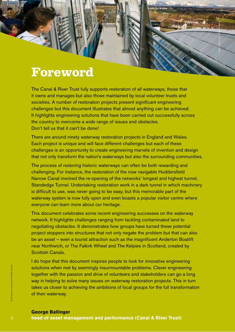
ForewordThe Canal & River Trust fully supports restoration of all waterways, those that it owns and manages but also those maintained by local volunteer trusts and societies. A number of restoration projects present significant engineering challenges but this document illustrates that almost anything can be achieved. It highlights engineering solutions that have been carried out successfully across the country to overcome a wide range of issues and obstacles. Don’t tell us that it can’t be done!
There are around ninety waterway restoration projects in England and Wales. Each project is unique and will face different challenges but each of these challenges is an opportunity to create engineering marvels of invention and design that not only transform the nation’s waterways but also the surrounding communities.
The process of restoring historic waterways can often be both rewarding and challenging. For instance, the restoration of the now navigable Huddersfield Narrow Canal involved the re-opening of the networks’ longest and highest tunnel, Standedge Tunnel. Undertaking restoration work in a dark tunnel in which machinery is difficult to use, was never going to be easy, but this memorable part of the waterway system is now fully open and even boasts a popular visitor centre where everyone can learn more about our heritage.
This document celebrates some recent engineering successes on the waterway network. It highlights challenges ranging from tackling contaminated land to negotiating obstacles. It demonstrates how groups have turned these potential project stoppers into structures that not only negate the problem but that can also be an asset – even a tourist attraction such as the magnificent Anderton Boatlift near Northwich, or The Falkirk Wheel and The Kelpies in Scotland, created by Scottish Canals.
I do hope that this document inspires people to look for innovative engineering solutions when met by seemingly insurmountable problems. Clever engineering together with the passion and drive of volunteers and stakeholders can go a long way in helping to solve many issues on waterway restoration projects. This in turn takes us closer to achieving the ambitions of local groups for the full transformation of their waterway.
George Ballinger head of asset management and performance (Canal & River Trust)
Cov
er p
hoto
cou
rtes
y of
Sco
ttis
h C
anal
s
Photo courtesy of S
cottish Canals

3
IntroductionWhat better way is there to show that something can be done than by showing how it has been achieved before? The purpose of this document is to demonstrate that obstacles faced in current restoration projects have been faced and overcome elsewhere.
The booklet is divided into sections:
These challenges are relatively common in waterway restoration, so to help you find a way around or over the problem, each section has at least one case study where the issue has been addressed and further contact details of those involved.
The chapters in this document were selected to show the scope of challenges in waterway restoration. The successes you will read about have been achieved through the input of project members working together to find engineering solutions. Many projects involved the dedication and skills of volunteers to make them happen and case studies were chosen to reflect this.
We hope that this document will inspire restoration groups, stakeholders and local authorities, with the belief that problems can be solved through clever engineering and thinking laterally.
1 Controlling Flooding
2 Bridge Reconstruction
3 Creating a Mooring Basin
4 Contaminated Land
5 Tunnels
6 Negotiating Obstacles
7 Boat Lifts
8 Improving Public Access
9 Creating a New Canal
10 Environmental Improvements
11 Restoring Locks
12 Creating a Staircase Lock
13 Tourist Attraction
Photo courtesy of S
cottish Canals

4
Engineering Case Studies
Anderton Boat Lift Trent & Mersey Canal7
Liverpool Canal Link Leeds & Liverpool Canal10
Middlewood Lock Manchester, Bolton & Bury Canal11
Rochdale – Tunnel under M62 Rochdale Canal5
Aston Nature Reserve Montgomery Canal9
Staircase Locks 4 & 5 Droitwich12
Over Basin Hereford & Gloucester Canal3
Dudbridge Stroudwater Navigation1
Upper Mills Bridge Stroudwater Navigation2
Dundas Aqueduct Kennet & Avon Canal6

Legend
Restoration Routes Navigable CRT Waterways
5
1 Controlling Flooding
2 Bridge Reconstruction
3 Creating a Mooring Basin
4 Contaminated Land
5 Tunnels
6 Negotiating Obstacles
7 Boat Lifts
8 Improving Public Access
9 Creating a New Canal
10 Environmental Improvements
11 Restoring Locks
12 Creating a Staircase Lock
13 Tourist Attraction
Falkirk Wheel Forth & Clyde Canal 7
Loxwood Drop Pound Wey & Arun Canal 11
Drungewick Aqueduct Wey & Arun Canal 6
A11 Bow ‘fly under’ River Lee Navigation 8
Reed beds Bow Creek 9
Steppingstone Lane Bridge Wilts & Berks Canal Trust 2
Capel Mills Cotswold Canals 4
Standedge Tunnel Huddersfield Narrow Canal 5
Dalmuir Drop Lock Forth & Clyde Canal 11
The Kelpies Forth & Clyde Canal 13
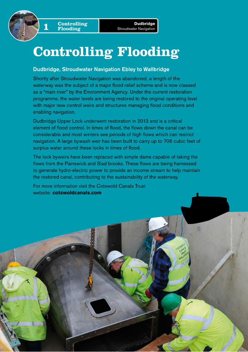
Controlling FloodingDudbridge, Stroudwater Navigation Ebley to Wallbridge
Shortly after Stroudwater Navigation was abandoned, a length of the waterway was the subject of a major flood relief scheme and is now classed as a “main river” by the Environment Agency. Under the current restoration programme, the water levels are being restored to the original operating level with major new control weirs and structures managing flood conditions and enabling navigation.
Dudbridge Upper Lock underwent restoration in 2013 and is a critical element of flood control. In times of flood, the flows down the canal can be considerable and most winters see periods of high flows which can restrict navigation. A large bywash weir has been built to carry up to 706 cubic feet of surplus water around these locks in times of flood.
The lock byweirs have been replaced with simple dams capable of taking the flows from the Painswick and Slad brooks. These flows are being harnessed to generate hydro-electric power to provide an income stream to help maintain the restored canal, contributing to the sustainability of the waterway.
For more information visit the Cotswold Canals Trust website: cotswoldcanals.com
6
Dudbridge Stroudwater Navigation
Controlling Flooding1
Photo courtesy of C
otswolds C
anal Trust

Bridge ReconstructionUpper Mills Bridge, Stroudwater Navigation
Upper Mills Bridge used to be a swing bridge that had, in its later life, been fixed and strengthened to accommodate increased vehicle weights, leaving not enough room for a boat to pass underneath. The crossing had been upgraded and maintained by the owners of the adjacent industrial estate under an agreement which gave them unfettered rights of access.
Various options were considered, including moving the entrance to the industrial estate, but the solution was to provide a fixed bridge located slightly (11 yards) to the north of the swing bridge.
Work commenced in the second half of 2010 to construct the new high-level fixed bridge that is seen today. The canal was also re-aligned and widened to give canal boats sufficient head room to go under the bridge. The slight change in location allowed for the provision of an acceptable gradient (1 in 9) into the estate.
Finishing touches to the project included landscaping work along the canal such as the edging of pre-planted coir rolls. This provided improvements in site biodiversity and encouraged flora and fauna into the area.
For more information visit the Cotswold Canals Trust website: cotswoldcanals.com
7
Upper Mills Bridge Stroudwater Navigation
Bridge Reconstruction2
Photo courtesy of C
otswolds C
anal Trust
Photo courtesy of C
otswold C
anals Trust

8
Steppingstone Lane bridge, Wilts & Berks Canal Trust
The original bridge was constructed in 1804/5 to carry the road from Shrivenham to Bourton. New access roads meant that this route became less popular and was a simple track and bridleway for many years. In the late 1940’s the bridge became unsafe, it was culverted and then collapsed onto the culvert.
Planning permission to rebuild the bridge was obtained in March 2000. Full excavation of the site started at the end of July 2002 with official approval of the diversionary route and the closure of the original bridleway.
It took 3 years to fully establish the condition of the remaining foundations, prepare construction plans for the new bridge, and to get approval from the County Council and to raise the funding for the purchase of materials. Volunteers throughout the Trust were eager to be involved as were volunteers from the Waterway Recovery Group (WRG).
The rebuilding of the bridge finally commenced, in earnest, in August 2006 and continued as labour, funds and weather permitted. 10 large, curved, steel formers, 10,000 facing bricks, 3000 engineering bricks plus quantities of cement, lime and sand were obtained and moved to the site. The bridge was rebuilt entirely by volunteers.
For more information visit the Wilts & Berks Canal Trust website: wbct.org.uk
Steppingstone Lane Bridge Wilts & Berks Canal Trust
Bridge Reconstruction2
Photo courtesy of W
ilts & B
erks Canal Trust
Pho
to c
ourt
esy
of V
augh
an W
elch

Photo courtesy of W
ilts & B
erks Canal Trust
Creating a Mooring BasinOver Basin, Hereford and Gloucester Canal
The Over Basin is situated on land of the former Over Isolation Hospital and was created in two and a half years opening in September 2000. The work was carried out by volunteers from the Herefordshire & Gloucestershire Canal Trust and teams of volunteers from the Waterway Recovery Group.
The first task for the volunteers was clearing the site which began in February 1998. Next work started on excavating the basin, which had been filled in when the hospital was built in 1903. A hospital mortuary block had once stood across the line of the canal, leaving heavy concrete foundations of which were successfully removed by the excavator team.
The slipway was laid with granite sets and the banks leading away from the basin sculptured into a gentle slope. These banks were seeded with grass and a wood chip towpath laid. The materials from the demolition of the hospital were recycled including thousands of heavy Victorian bricks that went into the building of the wharf walls.
The original clay that had lined the basin was used to line the sides. The basin was filled with water extracted from the River Leadon, and it took several days until the correct level was reached.
For more information visit the Herefordshire & Gloucestershire Canal Trust website: h-g-canal.org.uk
9
Over Basin Hereford & Gloucester Canal
Creating a Mooring Basin3
Pho
to c
ourt
esy
of V
augh
an W
elch

10
Contaminated LandCapel Mills, diversion through landfill site
The Capel Mills site in Stroud presented a huge challenge to the project team. The land was contaminated and the aim was to cut a new 350 yard section of canal through this land. This new section would link Capel Mills in Stroud, to the existing channel north of the A419 in the west to Arundel Aqueduct in the east, one of the biggest engineering challenges on the whole 37 mile Cotswold Canals restoration.
Adding to the complexity of this already difficult site, the land was constrained by a railway viaduct, and by the River Frome running along the southern boundary and a domestic landfill site which had created variable topography and required the removal and remediation of contaminated material.
An intrusive ground investigation on the landfill slopes was undertaken in order to determine the type of retaining wall construction required and associated material remediation. A 190 yard anchored contiguous piled wall was constructed to support the landfill slope and was installed using an “up and over” drilling approach.
The works were comprehensive but the main challenge was working with contaminated land. The project was environmentally sensitive and required the implementation of a wide reaching Construction Environmental Management Plan. All earthworks required a strict contaminated land recording and monitoring programme with all landfill material tested and sorted into segregated ‘suitable’ and ‘non-suitable’ material. An additional clay capping layer was also installed over an area of contaminated material with a gas vent system which mitigated the need to remove any landfill waste from the site.
For more information visit the Cotswold Canals Trust website: cotswoldcanals.com
Capel Mills Cotswold Canals
Contaminated Land4
Photo courtesy of A
lun Griffiths (contractors) Ltd.
11
Photo courtesy of A
lun Griffiths (contractors) Ltd.
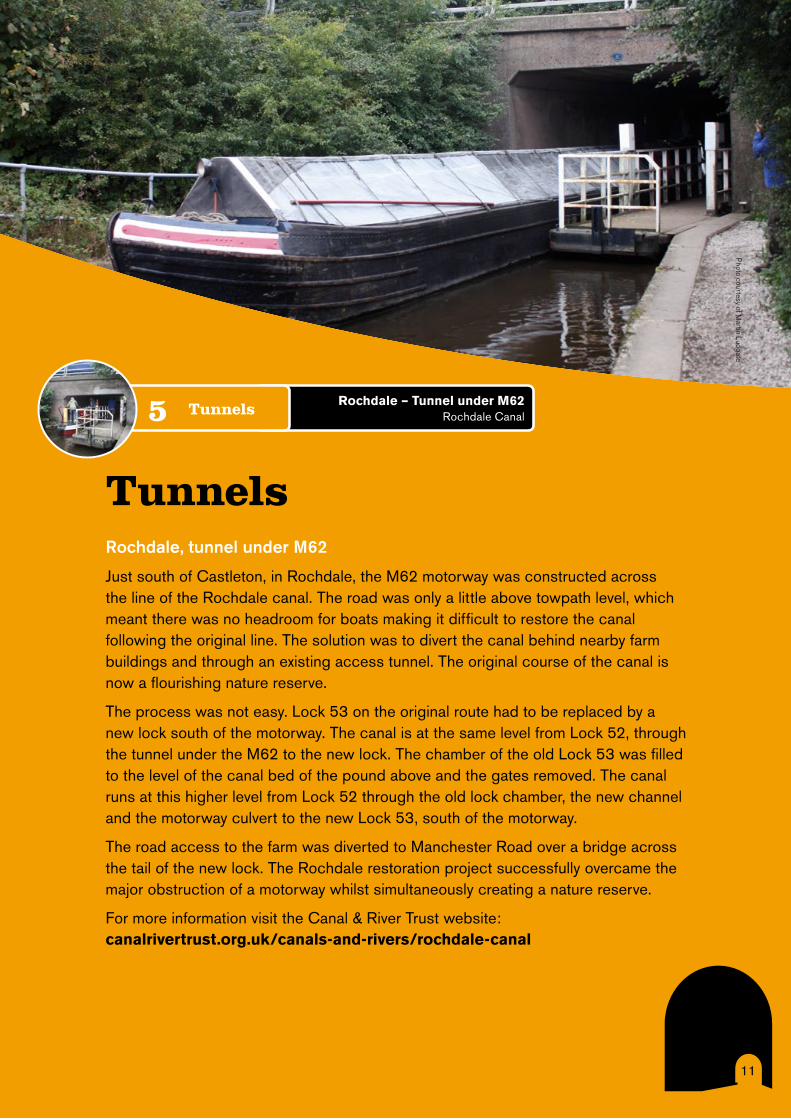
TunnelsRochdale, tunnel under M62
Just south of Castleton, in Rochdale, the M62 motorway was constructed across the line of the Rochdale canal. The road was only a little above towpath level, which meant there was no headroom for boats making it difficult to restore the canal following the original line. The solution was to divert the canal behind nearby farm buildings and through an existing access tunnel. The original course of the canal is now a flourishing nature reserve.
The process was not easy. Lock 53 on the original route had to be replaced by a new lock south of the motorway. The canal is at the same level from Lock 52, through the tunnel under the M62 to the new lock. The chamber of the old Lock 53 was filled to the level of the canal bed of the pound above and the gates removed. The canal runs at this higher level from Lock 52 through the old lock chamber, the new channel and the motorway culvert to the new Lock 53, south of the motorway.
The road access to the farm was diverted to Manchester Road over a bridge across the tail of the new lock. The Rochdale restoration project successfully overcame the major obstruction of a motorway whilst simultaneously creating a nature reserve.
For more information visit the Canal & River Trust website: canalrivertrust.org.uk/canals-and-rivers/rochdale-canal
Rochdale – Tunnel under M62 Rochdale CanalTunnels5
Photo courtesy of M
artin Ludgate
12
Standedge Tunnel
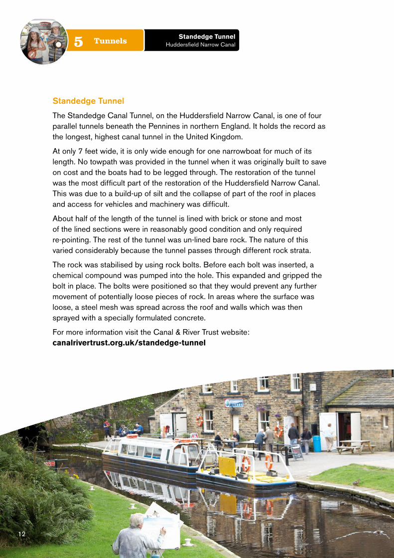
The Standedge Canal Tunnel, on the Huddersfield Narrow Canal, is one of four parallel tunnels beneath the Pennines in northern England. It holds the record as the longest, highest canal tunnel in the United Kingdom.
At only 7 feet wide, it is only wide enough for one narrowboat for much of its length. No towpath was provided in the tunnel when it was originally built to save on cost and the boats had to be legged through. The restoration of the tunnel was the most difficult part of the restoration of the Huddersfield Narrow Canal. This was due to a build-up of silt and the collapse of part of the roof in places and access for vehicles and machinery was difficult.
About half of the length of the tunnel is lined with brick or stone and most of the lined sections were in reasonably good condition and only required re-pointing. The rest of the tunnel was un-lined bare rock. The nature of this varied considerably because the tunnel passes through different rock strata.
The rock was stabilised by using rock bolts. Before each bolt was inserted, a chemical compound was pumped into the hole. This expanded and gripped the bolt in place. The bolts were positioned so that they would prevent any further movement of potentially loose pieces of rock. In areas where the surface was loose, a steel mesh was spread across the roof and walls which was then sprayed with a specially formulated concrete.
For more information visit the Canal & River Trust website: canalrivertrust.org.uk/standedge-tunnel
Standedge Tunnel Huddersfield Narrow CanalTunnels5

Negotiating Obstacles Drungewick Aqueduct
The original brick aqueduct which carried water over the Loxwood Stream was demolished in 1957 by the river authority to ease flood control. The original design shows a brick structure with two arches, although the aqueduct as built appears to have had three arches. When the aqueduct was rebuilt, the Environment Agency (EA) required the aqueduct to have an air draft to cope with worst case flooding. It was not possible to meet this requirement and maintain the canal bed at the same level as the original design, so a new design was needed.
Work started on the aqueduct in May 2002. One of the first operations in the project was to insert bored piling to support the foundations and then to bore 39 feet down for each of the 26 piles on the west bank. A temporary steel tube or sleeve was then driven into the bore hole. This sleeve is necessary in order to prevent water ingress into the bored hole from layers near the surface.
On the east bank the foundations of the original aqueduct remained under the site. Although this slowed down drilling the major problem was the effect of the old river bed, which meant that the sleeves had to be extended to 20 feet, and then to 30 feet, in order to prevent water getting into the bottom of the bored hole which was to be filled with concrete. To ensure that the concrete used for the piles was the right strength and quality, samples were tested by Portsmouth University.
The project was completed by contractors and volunteers and was opened on the 31 May 2003.
For more information visit the Wey & Arun Canal Trust website: weyandarun.co.uk
13
Drungewick Aqueduct Wey & Arun Canal
Negotiating Obstacles6
Photo courtesy of W
ey & A
run Canal Trust

14
Dundas Aqueduct
Dundas Aqueduct was the first canal structure to be designated as a Scheduled Ancient Monument; it is also a Grade 1 listed building. The aqueduct carries the Kennet & Avon Canal over the River Avon and the Wessex Main Line railway from Bath to Westbury, near Limpley Stoke in Wiltshire. It is named after Charles Dundas, the first chairman of the Kennet & Avon Canal Company. The aqueduct is 150 yards long with three arches built of Bath Stone, with Doric pilasters, and balustrades at each end.
The aqueduct was closed in 1954 after a number of leaks had developed. After a period of being used as a footpath, the aqueduct was brought back to life through an ambitious restoration project which saw the re-opening of the structure in 1984. The restoration process involved relining of the aqueduct, with polythene and concrete. The relining of the aqueduct channel was necessary as there were substantial leaks through the underside of the arch especially over the railway line (the River Avon and railway are right alongside each other and the aqueduct crosses both). A colony of bats had moved into the underneath of the aqueduct and care was taken not to disturb them during the restoration. The adjacent canal basin and the approach sections to the aqueduct were also lined.
Between 2002 and 2004 further restoration work was undertaken which included replacing engineering bricks used by Great Western Railway with Bath Stone to match the original Stone.
The eastern side arch of the aqueduct proved to be a challenge as the work to remove the sprayed concrete from the eastern side arch revealed greater repairs than were anticipated. The works were essential to prevent further damage, through ensuring that water is no longer trapped within the fabric of the structure. It was also needed to rectify the 1970’s unsightly repairs.
For more information visit the Canal & River Trust website: canalrivertrust.org.uk/places-to-visit/destination/48/dundas-aqueduct
Dundas Aqueduct Kennet & Avon Canal
Negotiating Obstacles6

Boat Lifts Falkirk Wheel
The jewel in the crown of the Millennium Link project, The Falkirk Wheel is designed to raise and lower boats between the 115 feet that separate the Union and Forth & Clyde canals. Opened in 2002, the Wheel is now a major Scottish landmark enjoyed by over 500,000 visitors per year.
The Wheel replaced 11 sets of lock gates which were long lost and remain buried beneath nearby streets. The Wheel is some 2 miles from the original locks on the site of a redundant tarworks. The design of the Wheel was developed over 5 years, evolving from a design based on the Greek Noria machine to an open cylindrical drum containing rotating gondolas to carry the boats.
Computer controlled motors raise and lower boats in two large gondolas. The prime mechanisms are hydraulic motors that rotate the Wheel’s two propeller–shaped arms and linked cogs that interact as the Wheel’s turn. Imposing stresses on the structure due to the weight of the water filled gondolas changing completely in direction. Instead of using normal welded joints, steel sections were bolted together, making them more robust and able to resist fatigue-induced stresses. The Wheel needs only 1.5 kW hours of electricity to complete a half turn, the equivalent of boiling eight household kettles.
The restoration of the canals has been a catalyst for investment across the rest of the waterways. The combination of engineering ingenuity and architectural imagination has ensured that the Wheel has become Scotland’s most unusual tourist attraction.
For more information visit the Scottish Canals website: scottishcanals.co.uk and: thefalkirkwheel.co.uk
15
Falkirk Wheel Forth & Clyde Canal
Boat Lifts7
Photo courtesy of S
cottish Canals

16
Left: Isometric drawing showing how the Wheel works
Left: Falkirk Wheel’s top approach and gondola
Left: Aerial view of the Wheel
Pho
tos
and
illus
trat
ion
cour
tesy
of S
cott
ish
Can
als

Anderton Boat Lift
The Anderton Boat Lift is located on the banks of the River Weaver at Northwich in Cheshire. A magnificent feat of engineering. It was built by Edwin Clark in 1875 to lift cargo boats the 50 feet from the River Weaver to the Trent & Mersey Canal. Like all great things, the concept is simple: two huge water tanks, each with watertight sealable doors to carry boats up and down. The original counter-balanced system was converted into an electrically driven mechanical operation by adding a new steel structure over the original lift. The lift continued to operate in this way until its closure in 1983 on safety grounds due to deterioration of the structural elements.
Investigations to restore the Anderton Boat Lift began in 1990. One significant issue was the way that the wedges were originally designed to separate the River Weaver sluice gates from the caisson gates. They were not effective enough to prevent significant water loss over an extended period and the pumps were being overwhelmed. Modifications in the early 20th century included the removal of this feature and the caissons subsequently operated in dry wells. However as a result of the original wedge design the well was flooding and undue stresses were being placed on the caissons and the structure itself by operating the caissons in a flooded well. Furthermore the state-of-the-art rams and their associated safety system were not designed to operate in a permanently submerged environment.
As a Scheduled Ancient Monument, any changes to the structure of the lift had to be approved by English Heritage. It was agreed that the hydraulic system would be restored which meant that more of the original historic structure could be saved. The engineering challenges associated with restoring a 125 year old structure and integrating it with a modern computerised hydraulic system were huge. In addition the project team only had 18 months to complete the project.
British Waterways (now Canal & River Trust) undertook to manage the technical risks by becoming client, designer and contractor all at once. The site team was 17 strong plus external consultants who assisted with various aspects of assessment and design.
A celebration of the refurbishment was held on 26 September 2001 and the lift fully opened to the public in 2003.
For more information visit the Canal & River Trust website: canalrivertrust.org.uk/anderton-boat-lift 17
Anderton Boat Lift Trent & Mersey Canal
Boat Lifts7

18
Improving Public AccessA11 Bow ‘fly under’
The building of a fixed walkway and bridge under the A11 Road in East London connected a ‘missing link’ of towpath on the River Lee Navigation. This resolved one of the last mis-connections of the 28 mile Lea Valley Walk and the new towpath brought benefits to walkers and cyclists who would no longer be forced to cross four lanes of traffic and would be able to enjoy an uninterrupted towpath.
The Canal & River Trust delivered the A11 Bow ‘fly under’: a 60 foot span steel bridge and extension to the towpath under the busy and dangerous A11/A12 junction where connection previously did not exist. This project was co-funded by the Trust with London Thames Gateway Development Corporation, Transport for London, Walk London and Design for London.
This unique structure is connected to a suspended pathway essentially creating a fly under the A11/A12 road junction. Due to the restricted nature of the site a floating 50 tonne crane was used to lift the 60 foot long and 10 foot wide bridge into place.
For more information visit the Canal & River Trust website: canalrivertrust.org.uk/canals-and-rivers/bow-back-rivers
A11 Bow ‘fly under’ River Lee Navigation
Improving Public Access8

Environmental Improvements Reed beds on Bow Creek
As part of the wider restoration of Bow Beck rivers and creation of Queen Elizabeth park, the Canal & River Trust worked with the Environment Agency to restore Bow Creek. The restoration included environmental improvements, for instance, eel passes were provided into the River Lee system at various locations including Bow Locks, Three Mills and Lea Bridge Weir. A further environmental improvement was the development of the reed beds on the Bow Creek which offer an important habitat to migratory wading birds, water fowl and fish.
The Canal & River Trust took inspiration from the creek, designing and fabricating gabion planters which are able to withstand boat collision and provide fish refuge to reduce predation by cormorants. These also offer an essential aesthetic improvement; masking the hard edges of the river bank and bringing colour and vibrancy back to the waterway whilst contributing towards the objectives of the Waterway Framework Directive. Over 1600 feet of the reed margin on the Lee Navigation, including those at Three Mills were created. This environment has proven beneficial for Shelduck, Tufted Duck, Teal and Pintail.
For more information visit the Canal & River Trust website: canalrivertrust.org.uk/canals-and-rivers/bow-back-rivers
19
Reed beds Bow Creek
Environmental Improvements9

20
Aston Nature Reserve, Montgomery Canal
Aston Nature Reserve was developed as part the environmental mitigation measures required to enable the restoration of the Montgomery Canal. The derelict canal had been designated a Special Area of Conservation, because of the wide range of aquatic plants including the rare floating water plantain. The biodiversity of the canal had to be maintained.
The Montgomery Canal Partnership developed a Conservation Management Strategy (CMS) which provided a framework for the on-going restoration of the canal and setting out the environmental mitigation measures. The CMS identified the need for new nature reserves, to offer a more secure and better suited environment for the aquatic plants and a diversity of wildlife.
The chosen site was water logged peat overlying sand, but the pond system required lining to maintain water levels in the canal and connectivity for the aquatic plants. The chosen solution was to use a flexible bentonite matting liner, with a continuous pumping system to keep the site dry during construction works.
Aston Nature Reserve was opened in 1994 and comprises of five interlinked ponds nearly 2 acres in size, with a through-flow of water. All the five main ponds contain plants transplanted from the main line of the canal. In addition to plant life the pools provide a home for several varieties of fish including Roach, Perch and Tench. It is now a designated SSSI because of the wide range of aquatic plants. Further reserves have been added following this successful design.
For more information visit the Friends of the Montgomery Canal website: montgomerycanal.me.uk/mwrt.html
Aston Nature Reserve Montgomery Canal
Environmental Improvements9

21
Creating a New CanalThe Liverpool Canal Link
The Liverpool Canal Link is now the centrepiece for the Pier Head and has helped to establish the Waterfront as Liverpool’s key tourist destination, animating the waterfront. This new canal connects the Leeds & Liverpool Canal, at Liverpool, to the South Docks. The new link adds 1¼ miles of navigable waterway to the canal system.
Creating this new canal was a huge undertaking with the chosen route including two new locks, open channels, tunnels and culverts. Two new highway bridges were built, as well as flow control structures and utility diversions.
A 21 foot wide channel was built through Trafalgar Dock which involved building a new fixed bridge and a lock at Prince’s Dock. A footbridge at Prince’s Dock was raised to allow boats to pass underneath and the bridge approaches have been landscaped. A new culvert across land known as Plot 7 was built along with another new culvert beneath St. Nicholas Place and the new Cruise Liner Facility.
Where the canal terminates at Canning Dock, part of the new link canal included the construction of a 547 yard stretch which included the building of bridge crossings and a lock. A new basin was built at Mann Island along with extensive landscaping to improve the area for the general public.
The actual engineering challenges were fairly straightforward using modern materials to modern design codes within an historic setting. The key challenges here were dealing with multiple authorities, funders, developers and landowners, overcoming multiple service clashes, a WWII unexploded bomb risk and generally constructing a project within a very busy public area.
The project was completed in 2008 and was opened in 2009.
For more information visit the Canal & River Trust website: canalrivertrust.org.uk/canals-and-rivers/liverpool-canal-link
Photo courtesy of Vaughan W
elch
Liverpool Canal Link Leeds & Liverpool Canal
Creating a New Canal10

Restoring Locks Dalmuir Drop Lock
Opened in 1790, the Forth & Clyde Canal crosses central Scotland at the narrowest part of the Scottish Lowlands providing a route for seagoing vessels between the Firth of Forth and the Firth of Clyde. Sadly, the canal fell into decline and closed in the mid-1960s, with several sections becoming blocked by roads.
At Dalmuir in Clydebank, the busy A814 crossed the canal via a swing bridge. Once the canal was closed, the swing bridge was replaced with a fixed span structure with only a 12 inch clearance above the waterway, preventing vessels from navigating that stretch of the canal.
As part of the millennium celebrations in 2000, National Lottery funds were used to bring the canal back to life and restore it to a navigable state. Solutions were needed to overcome the blockages and included a scheme that would effectively allow vessels to pass under the road bridge at Dalmuir.
The drop lock was the first of its kind to be installed in the UK and features a set of outward pointing mitre gates at each end of the lock, impounding 506,000 gallons of water. Once a vessel has entered the lock and the gates have been closed, the water is drained out to give up to 10 feet of clearance from the road bridge so the craft can pass. The lock can be emptied by pumping but as this uses a lot of electricity the method used when water supplies are adequate is to drain the lock to a nearby burn. The boat then moves forward under the bridge and the water is allowed back in before the exit gates are opened and the boat can depart.
Safety barriers are fitted to protect each set of mitre gates from the impact of a vessel, which could potentially cause the lock to flood rapidly. To prevent this, further safety barriers adjacent to each side of the road are fitted, which raise and lower with the changing water level in the lock. This prevents vessels from drifting underneath the road until it is safe to do so.
For more information visit the Scottish Canals website: scottishcanals.co.uk
22
Dalmuir Drop Lock Forth & Clyde Canal
Restoring Locks11
Pho
to c
ourt
esy
of S
cott
ish
Can
als
Pho
to c
ourt
esy
of W
ey &
Aru
n C
anal
Tru
st

Pho
to c
ourt
esy
of S
cott
ish
Can
als
23
Loxwood Drop Pound
One of the Trust’s most ambitious and challenging projects has been the restoration of the Loxwood canal crossing. The canal was abandoned in 1871 and the road bridge over the canal at Loxwood was removed in around 1900. To restore the bridge without changing the highway profile, the canal had to be lowered and an entirely new lock built on the upstream side to return the canal water to its historical level.
This was a major engineering exercise, achieved by lowering a 440 yard section of canal so that there is adequate headroom for a boat to pass under the road. At the southern end of the length, Brewhurst Lock was reconstructed reducing its fall from the original height of 8 feet, and hence lowering the level of the water in the pound crossed by the bridge. At the other end, a new lock (Loxwood Lock) was constructed, to provide for the difference between the new and original levels of the canal. In between, the canal bed was lowered, the banks shored up with piling, and a new winding hole created. The new bridge crosses the canal on a skew angle; the resulting ‘tunnel’ through which the canal passes is 25 yards long. The towpath runs through the tunnel, alongside the canal, and also allows pedestrians to cross the road safely; however, the restricted bridge height means horse riders must cross at road level. The work was completed, and the first boat passed under the new bridge into the new Loxwood Lock in April 2009.
For more information visit the Wey & Arun Canal Trust website: weyandarun.co.uk
Loxwood Drop Pound Wey & Arun Canal
Restoring Locks11
Pho
to c
ourt
esy
of W
ey &
Aru
n C
anal
Tru
st

24
Middlewood Locks
Middlewood Locks is the entrance to the, as yet unrestored, Manchester Bolton & Bury Canal in Salford, Greater Manchester. When the first section of the canal was restored, Locks 1 and 2, originally next to the junction with the River Irwell, needed to be relocated further away from the river, on the other side of the railway. The scheme was part of wider city centre regeneration scheme which means that the option to reinstate the canal at a later date was retained.
This complex project involved excavation and clearance of old foundations and services and the creation of locks, the realignment of canal channels, tunnelling under one of the busiest roads in Manchester City centre, the construction of new basins and the construction of what is now the third deepest canal lock in the country.
The project runs from the canal’s interface with the River Irwell, where the Canal & River Trust had installed a temporary dam and managed to retain the existing lock structure.
This project was not straight forward with many challenges:
• The design of the double depth lock had to be agreed with Network Rail to ensure the railway was unaffected by the works both during and after construction. Piles had to be meticulously set out to ensure that the lock was constructed in the correct position between the railway and the sewer.
• Water levels had to be controlled due to the proximity of the river, whilst creating the double depth lock.
• Part of the brief of the scheme was to restore as much of the old canal as possible.
The works were on site for over a year and incorporated the construction of 437 yards of canal channel and restoration as part of a larger development of a brownfield site in Salford.
For more information visit the Pennine Waterways website: penninewaterways.co.uk/mbb/mbbc41.htm and Manchester, Bolton & Bury Canal Society website: mbbcs.org.uk/index.html
Middlewood Lock Manchester, Bolton & Bury Canal
Restoring Locks11

Middlewood Lock Manchester, Bolton & Bury Canal
Restoring Locks11
25
Above: Lock featuring paddle gear
Above: Paddle gear in action
Above: Jim White, Technical Director Engineering, Cotswold Canals Trust
Paddle Gear Design and Development (using volunteer skills)
Part of the restoration of the Cotswold Canals involved developing paddle gear suitable for operation by the general public in the 21st century. The original gate paddle gear required the windlass operator to stand on the walkway across the lock gate, which is not safe. This meant that the design needed modification, whilst ensuring that the heritage was respected and that the paddle gear resembled as
much as possible how the equipment looked 100 years ago.
The final design visually echoes the gate and ground paddle gear as it was at the turn of the 20th century. Changes include using spheroidal graphite iron as opposed to cast iron with variations to the windlass and gear ratios.
Overall costs for the project were minimised through efficient design and the hands-on approach of volunteers. The Cotswold Canals Trust held workshops showing volunteers how to assemble and install paddle gear and they set up a heavy-duty woodworking facility so that volunteers could design and manufacture the wooden jack posts to mount the paddle gear.
For more information visit the Cotswold Canals Trust website: cotswoldcanals.com
Pho
tos
and
illus
trat
ion
cour
tesy
of C
otsw
old
Can
als
Trus
t
Paddle gear design Cotswold Canals Trust
Restoring Locks11

26
Creating a Staircase Lock The staircase lock, a small part of the full restoration project of the Droitwich Junction canal, is an engineering achievement in its own right. Built out of cast concrete the structure allows a rise of 20 feet. Staircase locks in general are a rarity on the canals and are all interesting examples of engineering. In a staircase lock the upper gate of one lock is the lower gate of another. The two locks were built in a staircase design to reduce the amount of embankment work involved in constructing the new channel. The lock functions by a lock chamber being filled using water from the lock immediately above it. On the top lock modifications were required to lower the discharge outlets of the paddles to be closer to the floor of the lock (to reduce turbulence).
On the staircase lock at Droitwich, there is a grill on the right hand side of the lower lock covering the weir which allows water to overflow so there is no need to empty the bottom lock before emptying the top lock. This improves the efficiency of the lock. The lock has been detailed with handmade bull nosed coping stone with volunteer carved sandstone specials at the corners.
For more information visit The Droitwich Waterways Trust website (formerly Droitwich Canals Trust): canalrivertrust.org.uk/canals-and-rivers/droitwich-canals
Staircase locks 4 & 5 Droitwich Junction Canal
Creating a Staircase Lock12
Pho
to c
ourt
esy
of T
he H
elix

27
Tourist AttractionThe Kelpies
Sitting close to The Falkirk Wheel on the Forth & Clyde Canal are two horse head sculptures which are almost 100 feet high – the largest artworks of their kind in the world. These magnificent steel plated sculptures are the centrepieces of the Helix project, which has regenerated 700 acres of under used land into a world-class parkland, visitor attraction and canal hub. By creating a sense of place, funding was secured to divert the canal and improve navigation. The scheme is driven by a partnership of Scottish Canals and Falkirk Council and supported by the Big Lottery Fund.
With a design inspired by the horse-powered heritage of the area and the colossal Clydesdales that once pulled barges along the canal in its heyday, The Kelpies stand guard over the eastern gateway to the Forth & Clyde Canal. Their name reflects the mythological transforming beasts possessing the strength and endurance of 10 horses. They are the largest works of art in Scotland, and the largest equine sculptures in the world.
The twin hollow heads weigh 300 tonnes and are each intricately formed of 500 separate steel plates to create a semi-translucent skin. Construction began in June 2013, and was completed by October 2013. However the highly complex design process took several years and ensured the structural integrity, wind loadings and material suitability for the full scale artworks. They tower either side of a new lock and their design is based on the original models produced by sculptor Andy Scott.
Along with a marina and canal extension, the lock provides a dramatic gateway to the Forth & Clyde from the River Carron.
For more information visit the Scottish Canals website: scottishcanals.co.uk and thehelix.co.uk
The Kelpies Forth & Clyde Canal
Tourist Attraction13
Pho
to c
ourt
esy
of T
he H
elix

28
Living waterways transform places and enrich livesIWA and Canal & River Trust would like to thank the following for photos and contributions to text: Alun Griffiths (contractors) Ltd., Cotswolds Canal Trust, Martin Ludgate, Scottish Canals, The Helix, Vaughan Welch, Wey & Arun Canal Trust, Wilts & Berks Canal Trust.
How to get involved• Would your local school, organisation or community like to get more
involved in your local waterway’s future?
• For more information on restoration projects please go to our website www.canalrivertrust.org.uk/restoration
Ways to contact the Restoration Team
Jason LeachE: [email protected]: 07810 378914
Address:Canal & River TrustPeel’s WharfLichfield StreetFazeleyTamworthB78 3QZ
Check out our website for updates:
canalrivertrust.org.uk/restoration
/canalrivertrust
@canalrivertrust
© Canal & River Trust is a charitable company limited by guarantee registered inEngland & Wales with company number 7807276 and charity number 1146792.
March 2015
FSC LOGO GOES
HERE
SUPPLIED BY PRINTER