EPDM, FKM, Kalrez - Steven Engineering · EPDM, FKM or Kalrez® Series LVM Piping/Mounting...
21
Wetted part material: Note) Kalrez ® is a registered trademark of DuPont Performance Elastomers. More variations! Orifice diameter 1.6 mm Orifice diameter 1.4 mm Orifice diameter 1.1 mm Orifice diameter 2 mm Note) LVM09/090 LVM10/100 LVM15/150 LVM20/200 LVM09/090 LVM10/100 LVM15/150 LVM20/200 Diaphragm PEEK EPDM, FKM, Service life: 10 million cycles or more (Based on SMC test conditions) Body/Plate Kalrez Series LVM Compact Direct Operated 2/3 Port Solenoid Valve for Chemicals Diaphragm Plate Choice of 281 VX2 VXD VXZ VXE VXP VXR VXH VXF VX3 VXA VCH VDW VQ LVM VCA VCB VCL VCS VCW Courtesy of Steven Engineering, Inc.-230 Ryan Way, South San Francisco, CA 94080-6370-Main Office: (650) 588-9200-Outside Local Area: (800) 258-9200-www.stevenengineering.com
Transcript of EPDM, FKM, Kalrez - Steven Engineering · EPDM, FKM or Kalrez® Series LVM Piping/Mounting...

Wetted part material:
Note) Kalrez® is a registered trademark of DuPont Performance Elastomers.
More variations!
Orifice diameter
1.6 mm
Orifice diameter
1.4 mm
Orifice diameter
1.1 mm
Orifice diameter
2 mm
Note)
LVM09/090 LVM10/100 LVM15/150 LVM20/200LVM09/090 LVM10/100 LVM15/150 LVM20/200
Diaphragm
PEEK
EPDM, FKM,Service life: 10 million cycles or more
(Based on SMC test conditions)
Body/Plate
Kalrez
Series LVMCompact Direct Operated 2/3 Port Solenoid Valve for Chemicals
Diaphragm
Plate
Choice of
281
VX2
VXD
VXZ
VXE
VXP
VXR
VXH
VXF
VX3
VXA
VCH�
VDW
VQ
LVM
VCA
VCB
VCL
VCS
VCW
Courtesy of Steven Engineering, Inc.-230 Ryan Way, South San Francisco, CA 94080-6370-Main Office: (650) 588-9200-Outside Local Area: (800) 258-9200-www.stevenengineering.com

LVM11
A
C
B
Meeting the most advanced needs of process control
� Valve chamber volume
� Change in volume depending on open/closed status of valve (pumping volume)
0.01 µl or less (Rocker type)
� Type with power-saving circuit can be selected.Holding power consumption can be reduced substantially.
Diaphragmvalve
Compact Direct Operated 2/3 Port Compact Direct Operated 2/3 Port
Series
Valve chamber volume
LVM09/090 LVM10(For LVM11)
LVM10/100 LVM15/150 LVM20/200
Unit: µl
18 11 20 50 84
“Pumping volume” refers to the volume of water that is expelled from the valve chamber, in which it is sealed, by the opening and closing action of the valve (once with no applied pressure).
With a normal diaphragm valve, because the valve chamber volume varies depending on ON or OFF status, a difference in volume is discharged into the outlet side of the valve when the valve is switched from ON to OFF. However, with a rocker type valve, there is almost no change in volume, and thus no fluid is discharged into the outlet side of the valve.
Visible changein volume
Difference in volume
ON status(Valve open)
OFF status(Valve closed)
ON status OFF status
Rockertype No change
in volume
Series
Power consumption
Inrush
Holding
LVM09/090 LVM10/100 LVM15/150 LVM20/200
Unit: W
3.3
0.9
2.5
1
5.5
1
4
0.6
� Space-savingSeries
Valve width
Manifold pitch
LVM090
9.5
10.5
LVM10/100
13
14
LVM150
16
17
LVM200
20
21
Unit: mm
Valve side
Manifold pitch
Analytical instruments for blood, urine, immune system, etc.
� Applications: Various analytical and inspection equipment
Refer to 10 in “Design and Selection” on the back of page 302, if the valve is to be energized continuously for extended periods of time, or used with a manifold.
282
LVM���(Rocker type)
B
C
A
PAT.PEND
A Valve chamber volumeB Body/Plate material: PEEKC Diaphragm material:
EPDM, FKM or Kalrez®
Series LVM
Piping/Mounting VariationsBody ported
Base mounted
• M5 thread • Tubing type
• Without sub-plate
• With sub-plate
LVM11 LVM10/100
LVM09/090 LVM10/100
LVM10/100
LVM15/150 LVM20/200
O-ring
Solenoid Valve for ChemicalsSolenoid Valve for Chemicals
2 x M5 x 0.8 Bracket(Optional)
Bracket (Optional)
Manual(Optional)
Tubing
283
VX2
VXD
VXZ
VXE
VXP
VXR
VXH
VXF
VX3
VXA
VCH�
VDW
VQ
LVM
VCA
VCB
VCL
VCS
VCW
Courtesy of Steven Engineering, Inc.-230 Ryan Way, South San Francisco, CA 94080-6370-Main Office: (650) 588-9200-Outside Local Area: (800) 258-9200-www.stevenengineering.com
3
N.C.
N.O.
N.C.
Universal
LVM09R3
LVM09R4
LVM095R
LVM11
LVM10R1
LVM10R2
LVM102R
LVM15R3
LVM15R4
LVM155R
LVM20R3
LVM20R4
LVM205R
N.C.
N.O.
Universal
N.C.
N.C.
N.O.
Universal
N.C.
N.O.
Universal
N.C.
N.O.
Universal
2
3
2
2
3
2
3
2
3
1.1
1.5
1.4
1.4
1.6 (1)
2
9.5
13
13
13
16
20
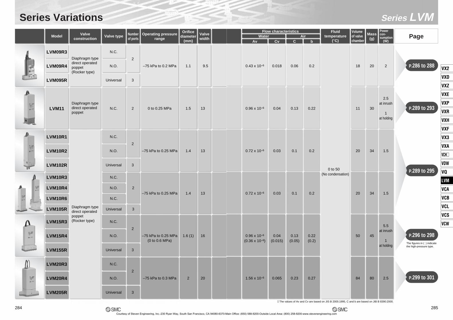
Series Variations
LVM10R3
LVM10R4
LVM10R6
LVM105R
2
Model Valveconstruction
Valve type Numberof ports
Valvewidth
Operating pressurerange
Orificediameter
(mm)
Diaphragm typedirect operatedpoppet(Rocker type)
Diaphragm typedirect operatedpoppet
Diaphragm typedirect operatedpoppet(Rocker type)
–75 kPa to 0.2 MPa
0 to 0.25 MPa
–75 kPa to 0.25 MPa
–75 kPa to 0.25 MPa
–75 kPa to 0.25 MPa
–75 kPa to 0.3 MPa
(0 to 0.6 MPa)
284
0.018
0.04
0.03
0.03
0.04
0.065
0.06
0.13
0.1
0.1
0.13
0.23
0.2
0.22
0.2
0.2
0.22
0.27
18
11
20
20
50
84
20
30
34
34
45
80
2
1.5
1.5
2.5
∗ The values of Av and Cv are based on JIS B 2005:1995, C and b are based on JIB B 8390:2000.
P.289 to 295
P.296 to 298
P.289 to 293
P.286 to 288
P.299 to 301
Av Cv C b
Series LVM
PageWaterFlow characteristics
AirFluid
temperatureVolumeof valvechamber
Mass(g)
Powercon-sumption
(°C) (W)
0.43 x 10⁻⁶
0.96 x 10⁻⁶
0.72 x 10⁻⁶
0.72 x 10⁻⁶
0.96 x 10⁻⁶
1.56 x 10⁻⁶
(0.36 x 10⁻⁶) (0.015) (0.05) (0.2)
0 to 50(No condensation)
2.5at inrush
1at holding
5.5at inrush
1at holding
The figures in ( ) indicate the high-pressure type.
285
VX2
VXD
VXZ
VXE
VXP
VXR
VXH
VXF
VX3
VXA
VCH�
VDW
VQ
LVM
VCA
VCB
VCL
VCS
VCW
Courtesy of Steven Engineering, Inc.-230 Ryan Way, South San Francisco, CA 94080-6370-Main Office: (650) 588-9200-Outside Local Area: (800) 258-9200-www.stevenengineering.com

Compact Direct Operated2/3 Port Solenoid Valve for Chemicals
Series LVM09/090How to Order
Specifications
LVM 09R3 5 A
(Symbol 1)IN
(Symbol 2)OUT
(Symbol 3)IN
(Symbol 2)OUT
3 1
2
Symbol
Symbol Valve typeNumberof ports
09R3
2
N.C.
09R4 N.O.
095R 3 Universal
DiaphragmEPDMFKM
Kalrez®
Wetted part materialSymbol Plate
PEEKPEEKPEEK
ABC
Lead wire lengthNil 150 mm
300 mm600 mm
36
∗ Nil cannot be selected in the case of function Y1.
FunctionNil Standard
With power-saving circuitY1
CE compliantNil None
CE compliantQ
Note 1) Select an appropriate material for the wetted part when fluid such as a cleaning solvent is used. Also, be sure to confirm the fluid compatibility in advance.Note 2) Indicates the pressure which does not generate breakage, cracks or external leakage after a one-minute airtight test.Note 3) Indicates the volume of clearance inside the valve chamber after the volume of the diaphragm is subtracted.Note 4) Since the body (orifice shape) is designed to eliminate residual liquid, mounting in a vertical direction with the coil at the top is recommended. When residual
liquid is not considered, any mounting orientation is available.Note 5) When the response speed is regarded as important, prevent negative fluctuation of the voltage by adequate regulation.Note 6) The value is based on SMC’s measurement conditions. The noise level will vary with conditions.Note 7) Refer to 10 in “Design and Selection” on the back of page 302, if the valve is to be energized continuously for extended periods of time.
Valve constructionValve typeNumber of portsFluid Note 1)
Operating pressure rangeOrifice diameterResponse timeLeakageProof pressure Note 2)
Ambient temperatureFluid temperatureVolume of valve chamber Note 3)
Mounting orientation Note 4)
EnclosureMassRated voltageAllowable voltage fluctuation Note 5)
Type of coil insulation
Power consumption(When rated voltage is at 24 V)
Standard
Withpower-savingcircuit
Inrush
HoldingCoil switching noise Note 6)
Diaphragm type direct operated poppet (Rocker type)
2N.C. N.O.
Air, Water, Pure water, Diluent, Cleaning fluid–75 kPa to 0.2 MPa
1.1 mm10 ms or less (at pneumatic pressure)
Zero leakage, either external or internal (at water pressure)0.3 MPa0 to 50°C
0 to 50°C (No condensation)18 µl
FreeIP40 or equivalent
20 g12, 24 VDC
±10% of rated voltageClass B
50 dB
2 W(0.08 A)
3.3 W(0.14 A)
0.9 W
Universal3
ModelLVM09R3 LVM09R4 LVM095R
Base mounted
Flow Characteristics
∗ The values of Av and Cv are based on JIS B 2005:1995, C and b are based on JIB B 8390:2000.
Av0.43 x 10–6
Cv0.018
C0.06
b0.2
Water Air
Coil voltage
56
24 VDC12 VDC
Symbol Voltage
Base Mounted
286Courtesy of Steven Engineering, Inc.-230 Ryan Way, South San Francisco, CA 94080-6370-Main Office: (650) 588-9200-Outside Local Area: (800) 258-9200-www.stevenengineering.com
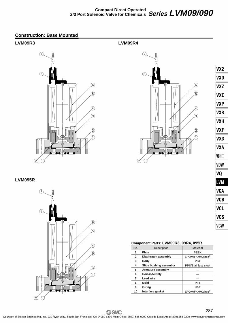
Construction: Base Mounted
LVM09R3 LVM09R4
LVM095R
1
2
3
4
5
6
7
8
9
10
DescriptionNo. Material
Component Parts: LVM09R3, 09R4, 095R
Plate
Diaphragm assembly
Body
Slide bushing assembly
Armature assembly
Coil assembly
Lead wire
Mold
O-ring
Interface gasket
PEEK
EPDM/FKM/Kalrez®
PBT
PPS/Stainless steel
—
—
—
PET
NBR
EPDM/FKM/Kalrez®
u
i
w !0
y
t
r
o
e
q
u
i
w !0
y
t
r
o
e
q
u
i
w !0
y
t
r
o
e
q
Series LVM09/090Compact Direct Operated2/3 Port Solenoid Valve for Chemicals
287
VX2
VXD
VXZ
VXE
VXP
VXR
VXH
VXF
VX3
VXA
VCH�
VDW
VQ
LVM
VCA
VCB
VCL
VCS
VCW
Courtesy of Steven Engineering, Inc.-230 Ryan Way, South San Francisco, CA 94080-6370-Main Office: (650) 588-9200-Outside Local Area: (800) 258-9200-www.stevenengineering.com

Dimensions: Base Mounted
LVM09R3LVM09R4LVM095R
∗ The broken lines indicate withpower-saving circuit.
LVM095R LVM09R3
LVM09R4
5.5
3
4
9.5 ± 0.1
19 ± 0.1 When using a positioning pin for mounting, please use ø1 and height 1.5 or less.
OUT
2 x M2 x 0.4Effective thread length3.5 or more
IN
2 x ø1.3C0.2 or less
3
5.5
4
3 x ø
3.6
4
ø1.2 depth 1.83
5.5
2 x ø
3.6
4
ø1.2 depth 1.8
35.5
2 x ø3.6
4
ø1.2 depth 1.8
5.5
3
4 4
9.5 ± 0.1
19 ± 0.1
When using a positioning pin for mounting, please use ø1 and height 1.5 or less.
2 (COM), OUT 3 (N.O)
Not required for LVM09R3
1 (N.C), IN
3 x ø1.3C0.2 or less
2 x M2 x 0.4Effective thread length3.5 or more
App
rox.
110
(F
or Y
1)
Approx. 5
≈40
App
rox.
150
(Le
ad w
ire le
ngth
)
1.5
7.5
32
7
App
rox.
300
(Le
ad w
ire le
ngth
for
Y1)(Y1 only)
With power-saving circuit
2 31
9.5UL1061AWG26
23.6
19
13.62 x ø2.1Mounting hole
Recommended interface dimensions ∗ Surface roughness = Rz3.2 or less
∗ Surface roughness = Rz3.2 or less
LVM09R4
LVM09R3, LVM095R
Series LVM09/090
288Courtesy of Steven Engineering, Inc.-230 Ryan Way, South San Francisco, CA 94080-6370-Main Office: (650) 588-9200-Outside Local Area: (800) 258-9200-www.stevenengineering.com

Compact Direct Operated2/3 Port Solenoid Valve for Chemicals
Series LVM10/100How to Order
LVM 11 5 ALVM 10R3 5 A 1
(Symbol 1)IN
(Symbol 2)OUT
(Symbol 3)IN
(Symbol 2)OUT
3 1
2
Symbol
11
Symbol Valve type
N.C.
Connection
OUT IN
Numberof ports
10R1 2 N.C.
10R2 N.O.
102R 3 Universal
M5 thread
Tubing type
OptionNil None
BracketManual override
Bracket, Manual override
123
∗ Only Option 1 can be selected for the LVM11
(Symbol 1)IN
(Symbol 2)OUT
(Symbol 3)IN
(Symbol 2)OUT
3 1
2
Symbol
Symbol Valve typeNumberof ports
10R3
2
N.C.
10R4 N.O.
10R6 N.C.
105R 3 Universal
OptionNil None
BracketManual override
Bracket, Manual override
123
Diaphragm
Wetted part materialSymbol Plate
EPDMFKM
Kalrez®
EPDMFKM
Kalrez®
PEEKPEEKPEEKPFAPFAPFA
ABCEFG
Sub-plate material/Port sizeNil Without sub-plate
PVDFPVDFPFAPFA
M61/4-28UNF
M61/4-28UNF
1∗
1U∗
22U
∗ Without a sub-plate, a bracket cannot be attached.
DiaphragmEPDMFKM
Kalrez®
Wetted part materialSymbol Plate
PEEKPEEKPEEK
ABC
(Symbol 1)IN
(Symbol 3)OUT
FunctionNil Standard
With power-saving circuitY Lead wire lengthNil 300 mm
600 mm1000 mm
610
CE compliantNil None
CE compliantQ
∗ For the LVM11, the type with power-saving circuit is standard.
Base Mounted
∗ Combinations with wetted part materials E, F, G. are not available.
Coil voltage
56
24 VDC12 VDC
Symbol Voltage
Body Ported
289
VX2
VXD
VXZ
VXE
VXP
VXR
VXH
VXF
VX3
VXA
VCH�
VDW
VQ
LVM
VCA
VCB
VCL
VCS
VCW
Courtesy of Steven Engineering, Inc.-230 Ryan Way, South San Francisco, CA 94080-6370-Main Office: (650) 588-9200-Outside Local Area: (800) 258-9200-www.stevenengineering.com

Specifications
Body ported
Body ported(Tubing type)
Note 1) Select an appropriate material for the wetted part when fluid such as a cleaning solvent is used. Also, be sure to confirm the fluid com-patibility in advance.
Note 2) Indicates the pressure which does not generate breakage, cracks or external leakage after a one-minute airtight test.Note 3) Indicates the volume of clearance inside the valve chamber after the volume of the diaphragm is subtracted.Note 4) Since the body (orifice shape) is designed to eliminate residual liquid, mounting in a vertical direction with the coil at the top is recom-
mended. When residual liquid is not considered, any mounting orientation is available.Note 5) When the response speed is regarded as important, prevent negative fluctuation of the voltage by adequate regulation.Note 6) The value is based on SMC’s measurement conditions. The noise level will vary with conditions. Note 7) Refer to 10 in “Design and Selection” on the back of page 302, if the valve is to be energized continuously for extended periods of time.Base mounted
(Without sub-plate)
Base mounted(With sub-plate)
Valve construction
Valve type
Number of ports
Fluid Note 1)
Operating pressure range
Orifice diameter
Response time
Leakage
Proof pressure Note 2)
Ambient temperature
Fluid temperature
Volume of valve chamber Note 3)
Mounting orientation Note 4)
Enclosure
Mass
Rated voltage
Type of coil insulation
Power consump-tion(When rated voltage is at 24 V)
Standard
Withpower-savingcircuit
In-rush
Hold-ing
Diaphragm typedirect operatedpoppet
Diaphragm type direct operated poppet (Rocker type)
N.C.
2
0 to 0.25 MPa
1.5 mm
11 µl
30 g
N.C.
2
Air, Water, Pure water, Diluent, Cleaning fluid
10 ms or less (at pneumatic pressure)
Zero leakage, either external or internal (at water pressure)
0.38 MPa
0 to 50°C
0 to 50°C (No condensation)
Free
IP40 or equivalent
12, 24 VDC
±10% of rated voltage
Class B
50 dB
1.5 W(0.06 A)
2.5 W(0.1 A)
1 W
—
34 g (without sub-plate), 42 g (with sub-plate)
20 µl
–75 kPa to 0.25 MPa
1.4 mm
3 32
ModelLVM105RLVM10R4 LVM10R6LVM10R3LVM102RLVM10R2LVM10R1
N.O. Universal N.C. N.O. N.C. Universal
LVM11
Body ported Body ported (Tubing type) Base mounted
Flow Characteristics
∗ The values of Av and Cv are based on JIS B 2005:1995, C and b are based on JIB B 8390:2000.
Direct operated poppet
Rocker type
Av
0.96 x 10⁻⁶
0.72 x 10⁻⁶
Cv
0.04
0.03
C
0.13
0.1
b
0.22
0.2
Valve constructionWater Air
Allowable voltage fluctuation Note 5)
Note 6)Coil switching noise
Series LVM10/100
290Courtesy of Steven Engineering, Inc.-230 Ryan Way, South San Francisco, CA 94080-6370-Main Office: (650) 588-9200-Outside Local Area: (800) 258-9200-www.stevenengineering.com

Construction: Body Ported
LVM11
LVM10R1 LVM10R2
LVM102R
!0
o
t
r
y
w
q
i
u
e
!1
1
2
3
4
5
6
7
8
9
10
11
DescriptionNo. Material
Component Parts: LVM11
Body
Diaphragm assembly
Spacer
Armature assembly
Coil assembly
Sleeve
Return spring
Board assembly
Casing
Plug
O-ring
PEEK
EPDM/FKM/Kalrez®
PBT
Stainless steel/POM
—
SUY
Stainless steel
—
PBT
NBR
NBR
1
2
3
4
5
6
7
8
9
10
11
12
13
DescriptionNo. Material
Component Parts: LVM10R1, 10R2, 102R
Plate
Diaphragm assembly
Body
Slide bushing assembly
Armature assembly
Coil assembly
Sleeve
Spacer
Return spring
Board assembly
Casing
Plug
O-ring
PEEK
EPDM/FKM/Kalrez®
PBT
POM/Stainless steel
Stainless steel/PBT
—
SUY
PBT
Stainless steel
—
PBT
NBR
NBR
!2
!1
y
t
u
o
w
q
!0
i
r
e
!3
!2
!1
y
t
u
o
w
q
!0
i
r
e
!3
!2
!1
y
t
u
o
w
q
!0
!3
i
r
e
Series LVM10/100Compact Direct Operated2/3 Port Solenoid Valve for Chemicals
291
VX2
VXD
VXZ
VXE
VXP
VXR
VXH
VXF
VX3
VXA
VCH�
VDW
VQ
LVM
VCA
VCB
VCL
VCS
VCW
Courtesy of Steven Engineering, Inc.-230 Ryan Way, South San Francisco, CA 94080-6370-Main Office: (650) 588-9200-Outside Local Area: (800) 258-9200-www.stevenengineering.com

LVM10R3
LVM105R
LVM10R4
1
2
3
4
5
6
7
8
9
10
11
12
13
14
DescriptionNo. Material
Component Parts: LVM10R3, 10R4, 10R6, 105R
Plate
Diaphragm assembly
Body
Slide bushing assembly
Armature assembly
Coil assembly
Sleeve
Spacer
Return spring
Board assembly
Casing
Plug
O-ring
O-ring
PEEK/PFA
EPDM/FKM/Kalrez®
PBT
POM/Stainless steel
Stainless steel/PBT
—
SUY
PBT
Stainless steel
—
PBT
NBR
NBR
EPDM/FKM/Kalrez®
LVM10R6
Construction: Base Mounted
!2 !0
i
!3
r
e
!4
!1
y
t
u
o
w
q
!2 !0
i
!3
r
e
!4
!1
y
t
u
o
w
q
!2 !0
i
!3
r
e
!4
!1
y
t
u
o
w
q
!2
!1
y
t
u
o
w
q
!0
i
!3
r
e
!4
Series LVM10/100
292Courtesy of Steven Engineering, Inc.-230 Ryan Way, South San Francisco, CA 94080-6370-Main Office: (650) 588-9200-Outside Local Area: (800) 258-9200-www.stevenengineering.com

Dimensions: Body Ported
LVM11-��-� (N.C.)
LVM10R1-��-� (N.C.)LVM10R2-��-� (N.O.)LVM102R-��-� (Universal)
LVM102R
LVM10R2
57
2.6
14.6
1.8(8.25)
12.5
9.5 5.1
7
16 App
rox.
300
13
2 x ø2.8
16.5
9.1
3 5.5
4.5
N.O.N.C.321
UL1007AWG22
Push typeManual override
2 x ø2.7 Mounting hole
4.5
2 x ø2.8
16.5
5.5
N.O.N.C.321
4.5
3 x ø2.8
16.5
5.5
4.5
N.O.N.C.321
(Lea
d w
ire le
ngth
)
∗ The broken lines indicate with bracket.
2 x ø3.2Mounting hole
25.4
19
(2 x R3.2)9
UL1007AWG22
M5 x 0.8OUT port
5
16
(Lea
d w
ire le
ngth
)
52.5
App
rox.
300
2
0.8
5
M5 x 0.8IN port
13
Series LVM10/100Compact Direct Operated2/3 Port Solenoid Valve for Chemicals
293
VX2
VXD
VXZ
VXE
VXP
VXR
VXH
VXF
VX3
VXA
VCH�
VDW
VQ
LVM
VCA
VCB
VCL
VCS
VCW
Courtesy of Steven Engineering, Inc.-230 Ryan Way, South San Francisco, CA 94080-6370-Main Office: (650) 588-9200-Outside Local Area: (800) 258-9200-www.stevenengineering.com
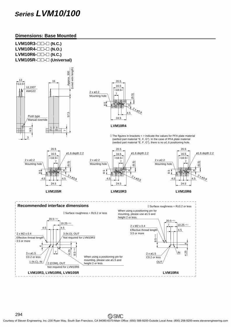
Dimensions: Base Mounted
LVM10R3-��-� (N.C.)LVM10R4-��-� (N.O.)LVM10R6-��-� (N.C.)LVM105R-��-� (Universal)
LVM10R4
LVM105R LVM10R6LVM10R3
∗ The figures in brackets < > indicate the values for PFA plate material(wetted part material “E, F, G”). In the case of PFA plate material (wetted part material “E, F, G”), there is no ø1.6 positioning hole.
Recommended interface dimensions ∗ Surface roughness = Rz3.2 or less
∗ Surface roughness = Rz3.2 or less
LVM10R4LVM10R3, LVM10R6, LVM105R
757
.5
9.5
1613
3
<13.5>UL1007AWG22
(Lea
d w
ire le
ngth
)
N.O.N.C.321
Push typeManual override
App
rox.
300
Effective thread length3.5 or more
2 x M2 x 0.4
4
7
20.5 ± 0.1
4.5
4.25
10.25 ± 0.1
OUT
IN
When using a positioning pin for mounting, please use ø1.5 and height 2 or less.
2 x ø1.5C0.2 or less
7
4
16.5
2 x ø3.9
(6.5
)
4.5
24.5
20.5
8.5
ø1.6 depth 2.2
<18.5>2 x ø2.2Mounting hole
4
7
16.5
2 x ø3.9
(6.5
)
4.5
24.5
20.5
8.5
<18.5>2 x ø2.2Mounting hole
7
4
16.5
2 x ø3.9
(6.5
)
4.54.5
24.5
20.5
8.5
ø1.6 depth 2.2
<18.5>2 x ø2.2Mounting hole
7
4
16.5
3 x ø3.9
(6.5
)
4.54.5
24.5
20.5
8.5
ø1.6 depth 2.2
<18.5>2 x ø2.2Mounting hole
2 x M2 x 0.4
20.5 ± 0.1
4.54.5
4.25
10.25 ± 0.1
8.5
± 0.
1
3 (N.O), OUTNot required for LVM10R3
2 (COM), OUTNot required for LVM10R6
1 (N.C), IN
Effective thread length3.5 or more
3 x ø1.5C0.2 or less
8.5
± 0.
1
7
4
When using a positioning pin for mounting, please use ø1.5 and height 2 or less.
Series LVM10/100
294Courtesy of Steven Engineering, Inc.-230 Ryan Way, South San Francisco, CA 94080-6370-Main Office: (650) 588-9200-Outside Local Area: (800) 258-9200-www.stevenengineering.com

LVM10R3-���-� (N.C.)LVM10R4-���-� (N.O.)LVM10R6-���-� (N.C.)LVM105R-���-� (Universal)
LVM10R4
LVM105R
∗ The broken lines indicate with bracket.
56
25.5
(2)
73.5
19
(16)
1111
6
13
12
27
24.5
36
21
1613
Plug
2 x M3 Thread length 5 For direct mounting
2 x ø3.5 Mounting hole
IN port3 x M6 x 1, 1/4-28UNFOUT port (LVM10R3, 10R4)
2 (COM) port (LVM105R)
Plug (LVM10R6)
UL1007AWG22
(Lea
d w
ire le
ngth
)
N.O.N.C.321
Push typeManual override
App
rox.
300
5
11 (16)
Plug IN port
N.O.N.C.321
1 2 3N.C. N.O.
10
11
OUT portIN port
LVM10R6
(16)
(16)
11
101 (N.C) port 3 (N.O) port
N.O.N.C.321
Dimensions: Base Mounted
Series LVM10/100Compact Direct Operated2/3 Port Solenoid Valve for Chemicals
295
VX2
VXD
VXZ
VXE
VXP
VXR
VXH
VXF
VX3
VXA
VCH�
VDW
VQ
LVM
VCA
VCB
VCL
VCS
VCW
Courtesy of Steven Engineering, Inc.-230 Ryan Way, South San Francisco, CA 94080-6370-Main Office: (650) 588-9200-Outside Local Area: (800) 258-9200-www.stevenengineering.com

Compact Direct Operated2/3 Port Solenoid Valve for Chemicals
Series LVM15/150How to Order
LVM 15R3Base Mounted
(Symbol 1)IN
(Symbol 2)OUT
(Symbol 3)IN
(Symbol 2)OUT
3 1
2
Symbol
Symbol Valve typeNumberof ports
15R3
2
N.C.
15R4 N.O.
155R 3 Universal
5 A
DiaphragmEPDMFKM
Kalrez®
Wetted part materialSymbol Plate
PEEKPEEKPEEK
ABC
Function
Standard (With power-saving circuit)High-pressure type (With power-saving circuit)
YHY
Lead wire lengthNil 300 mm
600 mm1000 mm
610
CE compliantNil None
CE compliantQ
Specifications
Note 1) Select an appropriate material for the wetted part when fluid such as a cleaning solvent is used. Also, be sure to confirm the fluid compatibility in advance.Note 2) Indicates the pressure which does not generate breakage, cracks or external leakage after a one-minute airtight test.Note 3) Indicates the volume of clearance inside the valve chamber after the volume of the diaphragm is subtracted.Note 4) Since the body (orifice shape) is designed to eliminate residual liquid, mounting in a vertical direction with the coil at the top is recommended. When residual
liquid is not considered, any mounting orientation is available.Note 5) When the response speed is regarded as important, prevent negative fluctuation of the voltage by adequate regulation.Note 6) The value is based on SMC’s measurement conditions. The noise level will vary with conditions.Note 7) Refer to 10 in “Design and Selection” on the back of page 302, if the valve is to be energized continuously for extended periods of time.
Valve constructionValve typeNumber of portsFluid Note 1)
Operating pressure rangeOrifice diameterResponse timeLeakageProof pressure Note 2)
Ambient temperatureFluid temperatureVolume of valve chamber Note 3)
Mounting orientation Note 4)
EnclosureMassRated voltageAllowable voltage fluctuation Note 5)
Type of coil insulation
Coil switching noise Note 6)
Power consumption(When rated voltage is at 24 V)
Inrush
Holding
Diaphragm type direct operated poppet (Rocker type)
2N.C. N.O.
Air, Water, Pure water, Diluent, Cleaning fluid–75 kPa to 0.25 MPa [0 to 0.6 MPa]
1.6 mm [1 mm]15 ms or less (at pneumatic pressure)
Zero leakage, either external or internal (at water pressure)0.38 MPa [0.9 MPa]
0 to 50°C0 to 50°C (No condensation)
50 µl
FreeIP40 or equivalent
45 g12, 24 VDC
±10% of rated voltageClass B
60 dB1 W
5.5 W(0.23 A)
Universal3
ModelLVM15R3 LVM15R4 LVM155R
Base mounted
[ ] indicates high-pressure type.
Flow Characteristics
∗ The values of Av and Cv are based on JIS B 2005:1995, C and b are based on JIB B 8390:2000.
Cv0.04
[0.015]
Av0.96 x 10–6
[0.36 x 10⁻⁶]
C0.13[0.05]
b0.22[0.2]
Water Air
Y
Coil voltage
56
24 VDC12 VDC
Symbol Voltage
Symbol Specifications
296
[ ] indicates high-pressure type.
Courtesy of Steven Engineering, Inc.-230 Ryan Way, South San Francisco, CA 94080-6370-Main Office: (650) 588-9200-Outside Local Area: (800) 258-9200-www.stevenengineering.com

1
2
3
4
5
6
7
8
9
10
DescriptionNo. Material
Component Parts: LVM15R3, 15R4, 155R
Plate
Diaphragm assembly
Body
Slide bushing assembly
Armature assembly
Coil assembly
Sleeve
Board assembly
Casing
Interface gasket
PEEK
EPDM/FKM/Kalrez®
PBT
PPS/Stainless steel
—
—
SUY
—
PBT
EPDM/FKM/Kalrez®
Construction: Base Mounted
LVM15R3 LVM15R4
LVM155R
u
i
o
!0
y
t
r
e
q
w
u
o
i
!0
y
t
r
e
q
w
u
i
o
!0w
q
y
t
r
e
Series LVM15/150Compact Direct Operated2/3 Port Solenoid Valve for Chemicals
297
VX2
VXD
VXZ
VXE
VXP
VXR
VXH
VXF
VX3
VXA
VCH�
VDW
VQ
LVM
VCA
VCB
VCL
VCS
VCW
Courtesy of Steven Engineering, Inc.-230 Ryan Way, South San Francisco, CA 94080-6370-Main Office: (650) 588-9200-Outside Local Area: (800) 258-9200-www.stevenengineering.com

Dimensions: Base Mounted
LVM15R3LVM15R4LVM155R
Recommended interface dimensions∗ Surface roughness = Rz3.2 or less∗ Surface roughness = Rz3.2 or less
LVM15R4LVM155R, LVM15R3
2 x M2.5 x 0.45
Effective thread length4.5 or more
5.5
Max
. 2.5
Min
. 0
Max. 9Min. 5.5
5.25
21.5 ± 0.1
10.75 ± 0.1
IN
OUT
When using a positioning pin for mounting, please use ø1.2 and height 2 or less.
2 x ø2.1C0.2 or less
10.5
27
21.5
2 x ø2.7Mounting hole
Max
. 2.5
Min
. 0
Max. 9Min. 5.5
Max. 9Min. 5.5
5.25
21.5 ± 0.1
10.75 ± 0.1
3 (N.O)Not required for LVM15R3
2 (COM), OUTWhen using a positioning pin for mounting, please use ø1.2 and height 2 or less.
1 (N.C), IN
2 x M2.5 x 0.45
Effective thread length4.5 or more
3 x ø2.1C0.2 or less
1
N.O.N.C.
32
48.6
App
rox.
300
(Lea
d w
ire le
ngth
)16
AWG22UL1007
10.5
± 0
.1
4.5
5.5
4.5
10.5
± 0
.1
Series LVM15/150
LVM15R4
LVM15R3
4.5
5.5
2 x R2.15
2 x
R2.
15ø1.4 depth 2.3
2.5
9
2.5
9
2.5
9 9
5.5
5.55.5 5.5
LVM155R
5.5
4.5
2 x R2.15
2 x
R2.
15
2 x R2.15
ø1.4 depth 2.3
4.5
5.5
2 x R2.15
2 x
R2.15
ø1.4 depth 2.3
298Courtesy of Steven Engineering, Inc.-230 Ryan Way, South San Francisco, CA 94080-6370-Main Office: (650) 588-9200-Outside Local Area: (800) 258-9200-www.stevenengineering.com
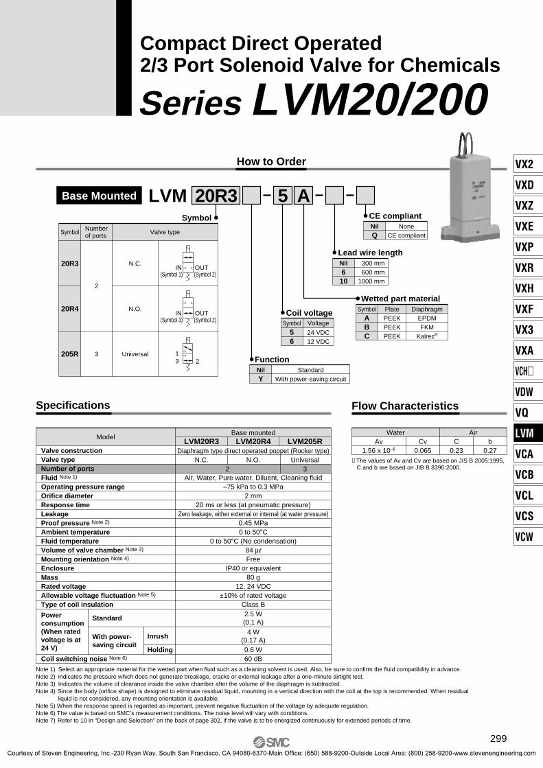
FunctionNil Standard
With power-saving circuitY
Compact Direct Operated2/3 Port Solenoid Valve for Chemicals
Series LVM20/200How to Order
LVM 20R3 5 A
(Symbol 1)IN
(Symbol 2)OUT
(Symbol 3)IN
(Symbol 2)OUT
3 1
2
Symbol
Symbol Valve typeNumberof ports
20R3
2
N.C.
20R4 N.O.
205R 3 Universal
DiaphragmEPDMFKM
Kalrez®
Wetted part materialSymbol Plate
PEEKPEEKPEEK
ABC
Lead wire lengthNil 300 mm
600 mm1000 mm
610
CE compliantNil None
CE compliantQ
Specifications
Note 1) Select an appropriate material for the wetted part when fluid such as a cleaning solvent is used. Also, be sure to confirm the fluid compatibility in advance.Note 2) Indicates the pressure which does not generate breakage, cracks or external leakage after a one-minute airtight test.Note 3) Indicates the volume of clearance inside the valve chamber after the volume of the diaphragm is subtracted.Note 4) Since the body (orifice shape) is designed to eliminate residual liquid, mounting in a vertical direction with the coil at the top is recommended. When residual
liquid is not considered, any mounting orientation is available.Note 5) When the response speed is regarded as important, prevent negative fluctuation of the voltage by adequate regulation.Note 6) The value is based on SMC’s measurement conditions. The noise level will vary with conditions.Note 7) Refer to 10 in “Design and Selection” on the back of page 302, if the valve is to be energized continuously for extended periods of time.
Valve constructionValve typeNumber of portsFluid Note 1)
Operating pressure rangeOrifice diameterResponse timeLeakageProof pressure Note 2)
Ambient temperatureFluid temperatureVolume of valve chamber Note 3)
Mounting orientation Note 4)
EnclosureMassRated voltageAllowable voltage fluctuation Note 5)
Type of coil insulation
Power consumption(When rated voltage is at 24 V)
Standard
With power-saving circuit
Inrush
HoldingCoil switching noise Note 6)
Diaphragm type direct operated poppet (Rocker type)
2N.C. N.O.
Air, Water, Pure water, Diluent, Cleaning fluid–75 kPa to 0.3 MPa
2 mm20 ms or less (at pneumatic pressure)
Zero leakage, either external or internal (at water pressure)0.45 MPa0 to 50°C
0 to 50°C (No condensation)84 µl
FreeIP40 or equivalent
80 g12, 24 VDC
±10% of rated voltageClass B
60 dB0.6 W
2.5 W(0.1 A)
4 W(0.17 A)
Universal3
ModelLVM20R3 LVM20R4 LVM205R
Base mounted
Flow Characteristics
∗ The values of Av and Cv are based on JIS B 2005:1995, C and b are based on JIB B 8390:2000.
Av1.56 x 10–6
Cv0.065
C0.23
b0.27
Water Air
Coil voltage
56
24 VDC12 VDC
Symbol Voltage
Base Mounted
299
VX2
VXD
VXZ
VXE
VXP
VXR
VXH
VXF
VX3
VXA
VCH�
VDW
VQ
LVM
VCA
VCB
VCL
VCS
VCW
Courtesy of Steven Engineering, Inc.-230 Ryan Way, South San Francisco, CA 94080-6370-Main Office: (650) 588-9200-Outside Local Area: (800) 258-9200-www.stevenengineering.com

Construction: Base Mounted
LVM20R3 LVM20R4
LVM205R
1
2
3
4
5
6
7
8
9
10
11
12
DescriptionNo. Material
Component Parts: LVM20R3, 20R4, 205R
Plate
Diaphragm assembly
Body
Slide bushing assembly
Armature assembly
Coil assembly
Sleeve
Board assembly
Casing
Plug
O-ring
O-ring
PEEK
EPDM/FKM/Kalrez®
PBT
PPS/Stainless steel
—
—
SUY
—
PBT
NBR
NBR
EPDM/FKM/Kalrez®
!0
u
!1
w !2
i
o
y
t
r
e
q
!0
u
!1
w !2
i
o
y
t
r
e
q
!0
u
!1
w !2
i
o
y
t
r
e
q
Series LVM20/200
300Courtesy of Steven Engineering, Inc.-230 Ryan Way, South San Francisco, CA 94080-6370-Main Office: (650) 588-9200-Outside Local Area: (800) 258-9200-www.stevenengineering.com

Dimensions: Base Mounted
LVM20R3LVM20R4LVM205R
Recommended interface dimensions∗ Surface roughness = Rz3.2 or less
∗ Surface roughness = Rz3.2 or less
LVM20R4LVM20R3, LVM205R
LVM205R LVM20R3
LVM20R4
13
37.4
31
2 x ø3.4Mounting hole
20
UL1007AWG22
58
9
24
App
rox.
300
321
(Lea
d w
ire le
ngth
)
N.O.N.C.
5
11
2 x ø5.7
6.8
ø2 depth 3
2 x M3 x 0.5Effective thread length4.5 or more
5
11
6.8 ± 0.1
15.5 ± 0.1
6.5
± 0.
1
13 ±
0.1
31 ± 0.1
IN
OUT
2 x ø2.3C0.2 or less
When using a positioning pin for mounting, please use ø1.8 and height 2.8 or less.
5
11
2 x ø
5.7
6.8ø2 depth 3
5
11
3 x ø5.7
6.86.8
ø2 depth 3
5
11
6.8 ± 0.16.8 ± 0.1
15.5 ± 0.1
6.5
± 0.
1
13 ±
0.1
31 ± 0.1
When using a positioning pin for mounting, please use ø1.8 and height 2.8 or less.
3 (N.C)Not required for LVM20R3
2 (COM), OUT
1 (N.C), IN
2 x M3 x 0.5Effective thread length4.5 or more
3 x ø2.3C0.2 or less
Series LVM20/200Compact Direct Operated2/3 Port Solenoid Valve for Chemicals
301
VX2
VXD
VXZ
VXE
VXP
VXR
VXH
VXF
VX3
VXA
VCH�
VDW
VQ
LVM
VCA
VCB
VCL
VCS
VCW
Courtesy of Steven Engineering, Inc.-230 Ryan Way, South San Francisco, CA 94080-6370-Main Office: (650) 588-9200-Outside Local Area: (800) 258-9200-www.stevenengineering.com

Series LVM Specific Product Precautions 1Be sure to read this before handling. Contact SMC when it is used in conditions other than the specifications.
WarningDesign and Selection
1. Do not use this product in applications which may adversely affect human life (e.g. medical equipment connected to the human body for drip infusion).
2. Confirm the specifications.Give careful consideration to the operating conditions such as the application, fluid and environment, and use within the oper-ating ranges specified in this catalog.
3. FluidBe sure to confirm the compatibility between the component material and the fluid.
4. Maintenance spaceThe installation should allow sufficient space for maintenance activities.
5. Fluid pressure rangeFluid pressure should be within the allowable pressure range.
6. Ambient environmentUse within the allowable ambient temperature range. Be sure that the fluid used does not touch the external surface of the product.
7. Countermeasures against static electricityTake measures to prevent static electricity since some fluids can cause static electricity.
8. Pressure (including vacuum) holdingIt is not usable for an application such as holding the pressure (including vacuum) inside of a pressure vessel because air leakage is entailed in a valve.
9. Cannot be used as an emergency shutoff valve, etc.The valves presented in this catalog are not designed for safe-ty applications such as an emergency shutoff valve. If the valves are used in this type of system, other reliable safety as-surance measures should also be adopted.
10. Extended periods of continuous energizationIf solenoid valves are to be continuously energized for exten-ded periods of time, use valves with power-saving circuits to minimize the amount of heat released by the coil.
The table below shows reference values for continuously energized valves (single unit) when surface temperature is 70°C or less.
When a solenoid valve without a power-saving circuit is contin-uously energized for long periods of time, temperature increase from coil heat release can result in worsening performance and shortened service life of the solenoid valve, as well as adverse effects on peripheral equipment in the vicinity. For this reason, when valves are to be continuously energized for extended periods, use a fan or take other measures to disperse heat and keep valve surface temperatures at 70°C or less.
11. Please use valve pitches equal to or above those shown in the table below when using multiple valves together.
Series
Valve pitch
LVM09/090 LVM10/100 LVM15/150 LVM20/20010.5 14 17 21
Power-saving circuit waveform (example)
Current consumption
(At holding 0.9 W)
0 V
Energization period of solenoid valve
(At inrush 3.3 W)
Approx. 100 msec
∗ Power consumption for the waveform shown above is that of the LVM09/090.∗ For the LVM15/150, the type with power-saving circuit is standard.∗ For the LVM10/100, the inrush is 50 msec.
Please use a fan or take other measures to disperse heat and keep temperatures within the specified range when mounting the solenoid valves inside control panels, etc. Be especially careful when using three or more adjacent valves with mani-folds and keeping them continuously energized for extended period, as this may result in dramatic increases in temperature.
∗ Duty ratio: ON time/(ON time + OFF time)∗ For the LVM15/150, the type with power-saving circuit is standard.
Series
Period of continuous energization
Duty ratio
Ambient temperature
Power-saving circuit
LVM09/090
5 min. or less
LVM10/100
30 min. or less
LVM20/200
30 min. or less
50% or less
25°C or less
None
Selection
Leakage voltageParticularly when using a resistor in parallel with a switching element and using a C-R element (surge voltage suppressor) to protect the switching element, take note that leakage current will flow through the resistor, C-R element, etc., creating a possible danger that the valve may not turn off.
Caution
Mounting
1. If air leakage increases or equipment does not oper-ate properly, stop operation.After mounting is completed, confirm that it has been done correctly by performing a suitable function test.
2. Since the body (orifice shape) is designed to elimin-ate residual liquid, mounting in a vertical direction with the coil at the top is recommended.When residual liquid is not considered, any mounting position is possible.
Warning
2% or less of rated voltage
Le
aka
ge
vo
lta
ge
Switching element
C
OFF
Leakage current
ValveR
Pow
ersu
pply
302Courtesy of Steven Engineering, Inc.-230 Ryan Way, South San Francisco, CA 94080-6370-Main Office: (650) 588-9200-Outside Local Area: (800) 258-9200-www.stevenengineering.com
Operating Environment
Warning
Maintenance
1. Removing the productShut off the fluid supply and release the fluid pressure in the system. Shut off the power supply. Remove the product.
2. Before operating, remove residual chemicals and completely replace it with deionized water, air, etc.
3. Do not disassemble the product.Products which have been disassembled cannot be guaran-teed. If disassembly is necessary, contact SMC.
Warning
1. Do not use in explosive atmospheres.2. Do not use in locations subject to excessive vibra-
tion or impact.Impact resistance of this solenoid valve is 150 m/s2. Vibration resistance of this solenoid valve is 30 m/s2.
3. Do not use in locations where radiated heat will be received from nearby heat sources.
1. Use electrical circuits which do not generate chat-tering in their contacts.
2. Use voltage which is within ±10% of the rated vol-tage.However, when the response time is important, control the vol-tage to avoid variation on the minus side.
3. Apply the correct voltage. Applying incorrect voltage may cause a malfunction or a burned coil.
4. Connect the wires so that an external force of greater than 10 N is not applied to the lead wire.Otherwise the coil will burn.
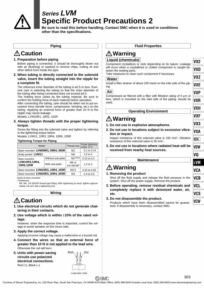
5. Units with power-saving circuits use polarized electrical connections.Red (+), Black (–)
Wiring
Caution
Black Red
Lead wire color
Fluid Properties
WarningPiping
1. Preparation before pipingBefore piping is connected, it should be thoroughly blown out with air (flushing) or washed to remove chips, cutting oil and other debris from inside the pipe.
2. When tubing is directly connected to the solenoid valve, insert the tubing straight into the nipple for a complete fit. The reference inner diameter of the tubing is ø2.5 or less. Exer-cise care in selecting the tubing so that the outer diameter of the tubing after being connected does not exceed ø4.5.The holding force varies by the tubing material. Be sure to confirm the holding force of each material before operation.After connecting the tubing, care should be taken not to put ex-cessive force (tensile force, compression, bending, etc.) on the tubing. Applying an external force of greater than 20 N to the nipple may cause leakage.Models: LVM10R1, 10R2, 102R
3. Always tighten threads with the proper tightening torque.Screw the fitting into the solenoid valve and tighten by referring to the tightening torque below.Models: LVM11, 10R3, 10R4, 10R6, 105R
Caution
Note) At base mounted∗ Reference
M5, M6, 1/4-28UNF thread type fitting: After tightening by hand, tighten approxi-mately 1/6 turn with a tightening tool.
Tightening Torque for Piping
Body ported LVM11
Model
Base mountedLVM10R3,10R4,10R6,105R
Base mounted LVM09R3, 09R4, 095R
Base mounted LVM15R3, 15R4, 155RBase mounted LVM20R3, 20R4, 205R
Without sub-plate
With sub-plate
Proper tighteningtorque N·m
0.1 to 0.14
1.5 to 2
0.15 to 0.2
1.5 to 2
0.25 to 0.35
0.4 to 0.6
Thread size
M2
M5
M2
M2.5
M3
M6 or1/4-28UNF
Series LVM Specific Product Precautions 2Be sure to read this before handling. Contact SMC when it is used in conditions other than the specifications.
Note)
Liquid (chemicals)Component crystallizes or clots depending on its nature. Leakage will occur when a crystallized or clotted component is caught be-tween the sealing parts.Take measures to clean such component if necessary.
WaterInstall a filter strainer of about 100 mesh on the inlet side of the pip-ing.
AirCompressed air filtered with a filter with filtration rating of 5 µm or less, which is mounted on the inlet side of the piping, should be used.
303
VX2
VXD
VXZ
VXE
VXP
VXR
VXH
VXF
VX3
VXA
VCH�
VDW
VQ
LVM
VCA
VCB
VCL
VCS
VCW
Courtesy of Steven Engineering, Inc.-230 Ryan Way, South San Francisco, CA 94080-6370-Main Office: (650) 588-9200-Outside Local Area: (800) 258-9200-www.stevenengineering.com