
EPAQ Qualitätsrichtlinien GB end · 2017-06-12 · – EN 1090-1 – Execution of steel structures...
92
QUALITY REGULATIONS FOR PANELS AND PROFILES OCTOBER 2016 European Association for Panels and Profiles
Transcript of EPAQ Qualitätsrichtlinien GB end · 2017-06-12 · – EN 1090-1 – Execution of steel structures...

QUALITY REGULATIONSFOR PANELS AND PROFILES
OCTOBER 2016
VERBINDUNGS- TECHNIK.
European Association for Panels and Profiles


QUALITY REGULATIONS FOR PANELS AND PROFILES (OCTOBER 2016) 3
European Association for Panels and Profiles
Contents
Scope 7
1. Quality Assurance System EPAQ 9
1.1. Terms and definitions 9
1.1.1. EPAQ 9
1.1.2. Third parties 9
1.1.3. Independent laboratories 9
1.1.4. Independent experts 10
1.1.4.1. General 10
1.1.4.2. Independent experts for fire 10
1.1.4.3. Independent experts for thermal characteristics 10
1.1.5. Independent auditing bodies 10
1.1.6. Test report 10
1.1.7. Evaluation report 10
1.1.8. Assessment report 10
1.1.9. Notified bodies 11
1.2. Basis of the Quality Assurance System 11
1.2.1. General 11
1.2.2. Requirements for third parties 11
1.2.3. Requirements for independent experts in the Quality Committees 12
1.2.4. Technical requirements 12
1.2.5. Assessment and verification of product performance 14
1.3. Procedural regulations for the award and use of the Quality Label EPAQ 15
1.3.1. Award of the Quality Label EPAQ 15
1.3.2. Use of the Quality Label EPAQ 16
1.3.3. Control of the Quality Label EPAQ 17
1.3.4. Penalties for deficiencies 17
1.3.5. Complaints 17
1.3.6. Re-award 18
1.4. Content of the Certification Document 20
2. Quality Regulations for Panels 23
2.1. Requirements for the panels properties 23
2.1.1. Tensile strength of the panel 23 2.1.2. Reaction to fire 23

European Association for Panels and Profiles
4 (OCTOBER 2016) QUALITY REGULATIONS FOR PANELS AND PROFILES
2.2. Control of the properties 23
2.2.1. General 23
2.2.2. Base material 23
2.2.3. Type testing 24
2.2.4. Initial Inspection and External Quality Control 25
2.2.5. FPC procedures 26
2.2.6. Type testing, EQC and FPC procedures for the thermal characteristics 27
2.3. Additional information for panels 31
2.3.1. Values under control / needed for different applications of panels 31
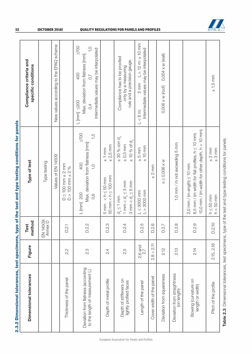
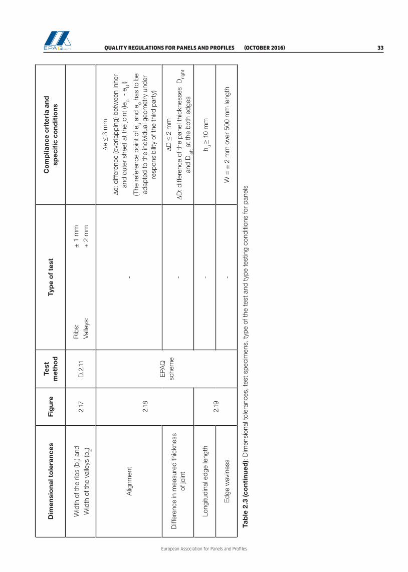
2.3.2. Dimensional tolerances, test specimens, type of the test and type testing conditions for panels 32
2.3.3. Dimensions of panels (examples for measurement) 35
2.3.4. FPC and external control procedures for panels 42
3. Quality Regulations for Profiles 45
3.1. Requirements for material properties 45
3.1.1. Nominal thickness 45
3.1.2. Reaction to fire 45
3.2. Control of material properties 45
3.2.1. General 45
3.2.2. Base material 46
3.2.3. Type testing 46
3.2.4. Initial Inspection and External Quality Control 47
3.2.5. FPC procedures 48
3.2.6. Measurement of dimensional characteristics 49
3.3. Additional information for profiles 57
3.3.1. Values controlled / needed for different applications 57
3.3.2. Type testing procedures for base material 58
3.3.3. Type testing procedures for profiles 59
3.3.4. Dimensional tolerances for trapezoidal profiles, test specimens, type of the test and conditions 60
3.3.5. Dimensional tolerances for sinusoidal profiles, test specimens, type of the test and conditions 63
3.3.6. Dimensional tolerances for liner trays, test specimens, type of the test and conditions 64
3.3.7. Dimensional tolerances for sidings / façade profiles, test specimens, type of the test and conditions 66
3.3.8. Dimensional tolerances for standing seam profiles, test specimens, type of the test and conditions 68
3.3.9. Dimensional tolerances for tiles, test specimens, type of tests and conditions 71
3.3.10. FPC procedures for base material and external control 72
3.3.11. FPC and external control procedures for profiles 73

QUALITY REGULATIONS FOR PANELS AND PROFILES (OCTOBER 2016) 5
European Association for Panels and Profiles
3.4. Dimensions of profiles 75
3.4.1. Dimensions of trapezoidal profiles 75
3.4.2. Dimensions of sinusoidal profiles and tiles 81
3.4.3. Dimensions of liner trays 84
3.4.4. Dimensions of sidings / façade profiles 88
3.4.5. Dimensions of standing seam profiles 90

European Association for Panels and Profiles
6 (OCTOBER 2016) QUALITY REGULATIONS FOR PANELS AND PROFILES

QUALITY REGULATIONS FOR PANELS AND PROFILES (OCTOBER 2016) 7
European Association for Panels and Profiles
Scope
The Quality Regulations for Panels and Profiles cover both, panels and cold-formed profiles. The first chapter of the document includes common information for both products. Specific regulations for panels are given in the second chapter and for profiles in the third chapter.
These Quality Regulations come into force after they have been accepted by the General Assembly of the ”European Association for Panels and Profiles” (PPA-Europe).
The latest version of these Quality Regulations has to be used in any case.
For all standards mentioned, the last version published in the Official Journal of the European Union (OJEU) is the basis of these Quality Regulations.
These Quality Regulations are valid for panels and profiles, which are covered by the scopes of the following harmonized European standards:
– EN 14509 – Self-supporting double skin metal faced insulating panels – Factory made products – Specifications
– EN 14782 – Self-supporting metal sheet for roofing, external cladding and internal lining for self-sup-porting profiles
– EN 1090-1 – Execution of steel structures and aluminium structures – Part 1: Assessment and verification of constancy of performance for structural components for structural profiles
It is the intention of these Quality Regulations to establish a quality assurance system for the fabrication of panels and profiles, mainly based on independent third party control. The behaviour, the geometry and the visual aspect of the products after installation do not constitute a subject matter of the quality assurance system.
The task of PPA-Europe is to get experienced third parties to ensure a quality assurance system. The EPAQ scheme requires (see also table 1.4):
– system A for mechanical and insulation properties,– system B for reaction to fire of panels,– system C for reaction to fire of structural profiles,– system D and E for reaction to fire of self-supporting profiles,– system D for tightness properties of panels.
AbbreviationsCD Certification DocumentEPS expanded polystyreneEQC External Quality ControlFPC Factory Production ControlhENs harmonized European standardsMW mineral woolPUR rigid polyurethane foam (PUR includes polyisocyanurate foam (PIR))

European Association for Panels and Profiles
8 (OCTOBER 2016) QUALITY REGULATIONS FOR PANELS AND PROFILES
QUALITY REGULATIONS FOR PANELS AND PROFILES (OCTOBER 2016) 9
European Association for Panels and Profiles
1 QUALITY ASSURANCE SYSTEM EPAQ
1.1 Terms and definitions
For the purposes of this document, the following terms and definitions apply.
1.1.1 EPAQEPAQ is the abbreviation for “European Panels and Profiles Assured Quality”. The Quality Label EPAQ will be awarded by the Quality Committees of the European Association for Panels and Profiles (PPA-Europe, or the association). A list of accepted parties according to 1.1.2 to 1.1.5 will be provided under the EPAQ scheme.
The Quality Label EPAQ, as well as the Certification Document and the Quality Certificate based on which it is awarded, are not a substitute for the mandatory CE marking and Declaration of Performance.
1.1.2 Third partiesThe tasks of third parties are:– Type testing and writing the test report;– Evaluation and preparation of evaluation report of type testing (task only for independent experts);– Responsibility for the initial inspection, including attending the inspection and writing the assessment
report;– Regular testing of samples as part of the EQC and writing the test report, the evaluation report and
the assessment report for EQC;– Responsibility for the regular assessment of the FPC as part of the EQC; including attending the
assessment and writing the FPC assessment report.
Third parties may be recognized for one or more fields of experience of the above mentioned tasks with regard to panels and/or profiles.
Third parties are:– Independent laboratories according to 1.1.3;– Independent experts according to 1.1.4;– A combination of an experienced independent expert acting together with a not-accepted or possibly
not impartial laboratory, or– independent laboratories or independent auditing bodies for initial inspection and regular assessment
of FPC.
1.1.3 Independent laboratoriesIndependent laboratories can only be laboratories with sufficient experience in testing of panels and/or profiles and in evaluation of test and test results of panels and/or profiles. Independent laboratories that are working under the EPAQ scheme should be bodies, notified by the notifying authorities of EU members states for products according to the standards mentioned in 1.2.
If an independent laboratory does not fulfil this requirement or if there is no notified body for some charac-teristics defined in the European product standards, the relevant Quality Committee can make a decision about the acceptance of the laboratory as an independent laboratory of the EPAQ scheme, by checking its competence in testing and/or evaluating test reports on panels/profiles.
Independent laboratories are not allowed to evaluate or to prepare the evaluation report of type testing. This task can only be done by an independent expert.

European Association for Panels and Profiles
10 (OCTOBER 2016) QUALITY REGULATIONS FOR PANELS AND PROFILES
1.1.4 Independent experts1.1.4.1 General
An independent expert is an individual or an individual within a testing laboratory with recognized knowled-ge in panels and/or profiles technology. In case of FPC assessment, it is also possible that the responsible independent expert is a member of an auditing body.
The independent experts of the Quality Committees have to decide on persons with enough knowledge on panels and/or profiles who want to become independent experts for one or more of the following tasks:
– Responsibility for the type testing according to 1.2.2.2.3, including attending the testing and writing the test report;
– Evaluation and preparation of evaluation report of type testing;– Responsibility for the initial inspection, including attending the inspection and writing the assessment
report;– Responsibility for the EQC, including attending the EQC and writing the test report, the evaluation
report and the assessment report for EQC.
1.1.4.2 Independent experts for fireThe independent experts for fire are nominated by the existing independent experts for fire of the associati-on. Their task is to check the data regarding fire and to analyse the range of validity of existing test reports.
1.1.4.3 Independent experts for thermal characteristicsThe independent experts for thermal characteristics are nominated by the existing independent experts for thermal characteristics of the association. Their task is to evaluate the results of the type testing of λ, to calculate or check the U-values and to analyse the range of validity of existing test reports.
1.1.5 Independent auditing bodiesIn case of initial inspection and regular FPC assessment, the auditing body is responsible for assessment and writing the assessment report. The independent experts of the Quality Committees decide on the auditing bodies that are working under the EPAQ scheme.
1.1.6 Test reportIncludes all basic test results without calculation of statistical evaluation and other further steps.
1.1.7 Evaluation reportReport worked out by an independent expert determining basic values and properties as a base for awar-ding and maintenance of the Quality Label on the base of the relevant assessment and test reports.
The evaluation report drawn up by an independent expert for fire is called “Assessment report for fire pro-perties” and the evaluation report drawn up by an independent expert for thermal characteristics is called “Assessment report for thermal characteristics”.
1.1.8 Assessment reportThe reviews are the result from EQC and FPC in comparison to declared values on the Declaration of Performance and on the Certification Document and in comparison to the requirements of these Quality Regulations.
Assessment reports and summaries have to be written in English, the rest can be written in the language of origin of the third party. If there are problems, the relevant Quality Committee can ask for an English version.

QUALITY REGULATIONS FOR PANELS AND PROFILES (OCTOBER 2016) 11
European Association for Panels and Profiles
1.1.9 Notified bodiesBodies assessed and notified by notifying authorities designated by the member states of the EU that are authorised to carry out third party tasks in the process of assessment and verification of constancy of performance for the purposes of the Construction Product Regulation. According to the relevant hENs for panels, profiles (see Scope) and used core materials, notified bodies are active for fire and insulation properties only.
1.2 Basis of the Quality Assurance System
1.2.1 General1.2.1.1 Technical basis
Technical basis of the quality assurance system are the European standards:
– EN 14509 for panels;– EN 14782 for self-supporting profiles;– EN 1090 for structural profiles,
when there are no special regulations given by the Quality Committees. The rules of the Quality Regulations are valid for products used for applications, which are for normal European outdoor and indoor conditions in normal buildings, including cold stores.
Concerning the reaction to fire of the products according to EN 14509, the manufacturers must own the certificate of constancy of performance of the product drawn up by a notified product certification body.
Concerning the reaction to fire of the products according to EN 1090-1, the manufacturers must own the certificate of conformity of the FPC drawn up by a notified production control certification body.
1.2.1.2 Quality management systemCompanies with a Quality Label EPAQ shall have a quality management system ISO 9001-2008 or higher with implemented FPC, or have to follow the requirements of a quality management system ISO 9001-2008 or higher with implemented FPC.
1.2.2 Requirements for third parties1.2.2.1 General
The third parties for testing and the third parties for evaluation and assessment have to attend the annual meetings of the third parties under the EPAQ scheme, to give reports about their work and to be informed about the quality assurance work of PPA-Europe. In case of absence or not fulfilling their duties, the follo-wing action plan is applied:
− 1st absence or contravention: Info about the obligation to attend the meetings or to fulfil its duties and the consequence that the status as third party will be denied after the 3rd absence or contravention;
− 2nd absence or contravention: Letter to explain the obligation to attend the meetings and the consequence that the status as third party will be denied after the 3rd absence or contravention;
− 3rd absence or contravention: Denial of the status as third party under the EPAQ scheme.
1.2.2.2 Requirements for third parties for testing1.2.2.2.1 General requirements
The Testing Rules of the EPAQ scheme have to be applied by testing panels/profiles. It is not permitted to deviate from the testing procedures established in EN 14509 for panels, EN 14782 for self-supporting profi-les and/or EN 1090 for structural profiles and the Testing Rules of the association.

European Association for Panels and Profiles
12 (OCTOBER 2016) QUALITY REGULATIONS FOR PANELS AND PROFILES
Third parties for testing are either independent laboratories with sufficient experience in panels/profiles tes-ting and evaluation of panels/profiles test results according to 1.2.2.2.2 or a combination of an experienced independent expert acting together with a not-accepted or possibly not impartial laboratory according to 1.2.2.2.3.
1.2.2.2.2 Requirements for independent laboratories for testingIndependent laboratories for testing must fulfil the requirements according to 1.1.3 and have to work in accordance to the requirements of EN ISO 17020 and EN ISO 17025.
1.2.2.2.3 Requirements for independent experts working with laboratoriesIndependent experts working together with laboratories can form a third party body.
An independent expert can work with external laboratories, which either do not conform to 1.2.2.2.2 or do not have the necessary experience to perform adequate testing or he can work with a manufacturer’s laboratory, where the independent expert insures adequacy of testing facilities and procedures as well as independency of the laboratory.
1.2.2.3 Requirements for third parties for evaluation and assessment1.2.2.3.1 General requirements
The evaluation work of the type testing can be undertaken only by independent experts (see 1.1.4), initial inspection of the plant and regular assessment of FPC can be undertaken by independent laboratories, by independent auditing bodies or by independent experts (see 1.1.3, 1.1.4 and 1.1.5), writing of the EQC assessment report can be undertaken only by independent laboratories or independent experts (see 1.1.3 and 1.1.4). Each independent laboratory has to appoint one or more of its employees as responsible for the EPAQ EQC. The Quality Committees have to confirm the appointments.
1.2.2.3.2 Requirements for independent laboratories for evaluation and assessmentIndependent laboratories must fulfil the requirements according to 1.1.3.
1.2.2.3.3 Requirements for independent experts for evaluation and assessmentIndependent experts for evaluation and assessment must fulfil the requirements according to 1.1.4.
Independent experts for fire must fulfil the requirements according to 1.1.4.2.
Independent experts for thermal characteristics must fulfil the requirements according to 1.1.4.3.
1.2.2.3.4 Requirements for independent auditing bodies for assessmentIndependent auditing bodies for assessment must fulfil the requirements according to 1.1.5.
1.2.3 Requirements for independent experts in the Quality Committeesn1.2.3.1 At least two independent experts are elected members of each Quality Committee. They have to be elected
by the General Assembly (see Statutes, Article 9).
1.2.3.2 The independent experts of the Quality Committees have to have good experience in testing and in evaluating test results of panels and/or profiles..
1.2.4 Technical requirements1.2.4.1 Table 2.2 shows a list of properties for panels and table 3.1 for profiles, which are under control of the EPAQ
scheme concerning the different applications.Frequency of testing and the number of samples for FPC and external control are regulated in Table 2.4 for panels and in Tables 3.8 and 3.9 for profiles.

QUALITY REGULATIONS FOR PANELS AND PROFILES (OCTOBER 2016) 13
European Association for Panels and Profiles
In case of:– dimensional tolerances,– mechanical resistance,– durability, where required,– thermal insulation performance,
the parties involved in the voluntary quality assurance system of the association have the following tasks (see Table 1.1 below):
Duty Outcome Party involved
Type testing Test report Third party according to 1.2.2.2
Evaluation of the type testing on mechanical and dimensional cha-racteristics
Evaluation report Third party according to 1.2.2.3.3
Evaluation of the type testing of λ - and calculation/checking of U-values
Assessment report for ther-mal characteristics
Third party according to 1.2.2.3.3
Initial inspection Assessment report Third party according to 1.2.2.3
Regular testing of samples within EQC
Test report, evaluation report and assessment report for EQC
Third party according to 1.2.2.2
Regular FPC assessment within EQC
FPC assessment report Third party according to 1.2.2.3
Table 1.1: Tasks of involved parties concerning mechanical characteristics, dimensional characteristics, durability and thermal insulation performance
1.2.4.2 In case of:– Reaction to fire– Fire resistance, where required– External fire performance, where required
the parties involved in the voluntary quality assurance system of the association have the following tasks (see Table 1.2 below):
Duty Outcome Party involved
Analysis of type testing data regar-ding fire performance
Assessment report for fire properties
Third party according to 1.2.2.3.3
Regular FPC assessment within EQC (in case of reaction to fire)
FPC assessment report Third party according to 1.2.2.3
Table 1.2: Tasks of involved parties concerning fire performance
Test reports and classification reports are to be provided if no CWFT-decision exists.
1.2.4.3 In case of:All other properties (e.g. tightness performance), the parties involved in the voluntary quality assurance sys-tem of the association have the following tasks (see Table 1.3 below):

European Association for Panels and Profiles
14 (OCTOBER 2016) QUALITY REGULATIONS FOR PANELS AND PROFILES
Duty Outcome Party involved
Type testing Test report Third party according to 1.2.2.2
Evaluation of the type testing Evaluation report Third party according to 1.2.2.3.3
Regular testing of samples within EQC
Test report and evaluation report
Third party according to 1.2.2.2
Regular FPC assessment within EQC (where required)
FPC assessment report Third party according to 1.2.2.3
Table 1.3: Tasks of involved parties concerning other properties
1.2.5 Assessment and verification of product performanceIn order to ensure that the performance is accurate and reliable, the performance of the product should be assessed and the production in the factory should be controlled in accordance with an appropriate system of assessment and verification of performance of the product. Under the EPAQ scheme, several systems have been established to be applied for panels and profiles, in order to take into account the specific relationship of some of its essential characteristics to the requirements of a good product quality (Table 1.4).
Tasks
EPAQ Systems
A B C D E
Man
ufac
ture
r
Determination of the product-type on the basis of type testing (including sampling), type calculation, tabulated values or descriptive documentation of the product
X X
Factory Production Control X X X X X
Further testing of samples taken at the factory in accordance with the prescribed test plan
X X X
Third
par
ty
Determination of the product-type on the basis of type testing (including sampling), type calculation, tabulated values or descriptive documentation of the product
X X X
Initial inspection of the manufacturing plant and of factory production control
X X X
Continuous surveillance, assessment and evaluation of factory production control
X X X
Audit-testing of samples taken before placing the product on the market with the Quality Label EPAQ
X
Table 1.4: EPAQ systems of assessment and verification of product performance

QUALITY REGULATIONS FOR PANELS AND PROFILES (OCTOBER 2016) 15
European Association for Panels and Profiles
1.3 Procedural regulations for the award and use of the Quality Label EPAQ
1.3.1 Award of the Quality Label EPAQ1.3.1.1 The applicant has to submit the “Application form for the award of the Quality Label EPAQ” to the secretariat
of the “European Association for Panels and Profiles” with clear specification of the range of the products for which the Quality Label EPAQ is wished. The application has to be accompanied by a signed and legally binding certificate of undertaking.
1.3.1.2 The association awards, under contract, the right to use the Quality Label “European Panels and Profiles Assured Quality” (EPAQ) to manufacturers of panels and/or profiles that maintain the compliance with these Quality Regulations. The award of the quality label is only made, in a given instance, in respect of one specific group of products.
1.3.1.3 The Quality Regulations for Panels and Profiles are extended and further developed to match the technical progress made in this area.
1.3.1.4 The procedure that has to be followed to get a quality label is described below: – The applicant informs the secretariat about its chosen third parties responsible for the different cha-
racteristics; which will be certified.– For panels:
– The third party for type testing of the mechanical and dimensional characteristics;– The independent expert for fire (at least, the reaction to fire has to be certified);– The independent expert for thermal characteristics
– For profiles:– The third party for type testing of the mechanical and dimensional characteristics;– The independent expert for fire (at least, the reaction to fire has to be certified).
– The third parties inform the applicant about the necessary tests and/or documents. It is recommen-ded that the chosen third parties meet to correlate their work. The third parties are bound to secrecy in respect of third parties.
– Type testing and writing of test report on the mechanical and dimensional characteristics by a third party for testing (see 1.2.2.2).
– Evaluation of the type testing results, given in a separate evaluation report by an independent expert for evaluation (see 1.2.2.3.3). The reports are passed on to the applicant and to the secretariat of the association.
– Checking of the evaluation (including test report and/or evaluation report) by an independent expert of the relevant Quality Committee (see 1.2.3). This independent expert must be different from the independent expert who has done the evaluation.
– The independent experts of the relevant Quality Committee can decide on additional independent experts for checking the evaluation reports.
– The independent expert for fire analyses the type testing data regarding the fire performance of the products and forwards the results of his analysis within the assessment report for fire properties to the secretariat of the association and to the chairman of the relevant Quality Committee.
– In case of panels, an independent laboratory for λ-testing carries out type testing of the thermal con-ductivity. This can be done in parallel with the type testing of the mechanical and dimensional charac-teristics. The independent expert for thermal characteristics analyses and confirms the λ-test reports, calculates or checks the calculation of the U-values and forwards the results of his analysis within the assessment report for thermal characteristics to the secretariat of the association and to the chair-man of the Quality Committee for Panels.
– One of the above mentioned third parties involved in the certification process has to prepare a first draft Certification Document by filling in the characteristics which were under its responsibility (me-chanical and dimensional / fire / thermal ) and has to send it to the secretariat. The secretariat has to forward the draft for completion to the other involved third parties.

European Association for Panels and Profiles
16 (OCTOBER 2016) QUALITY REGULATIONS FOR PANELS AND PROFILES
The Certification Document filled by all involved third parties is checked by the secretariat of the asso-ciation, after which it is forwarded to the chairman of the relevant Quality Committee. The final form of the Certification Document has to be signed by the chairman of the relevant Quality Committee. The Certification Document has a validity period of six years. When the Certification Document reaches the expiry date, the secretariat has to perform a formal check of the content, after which the Certifi-cation Document can be renewed. For the renewal, the secretariat needs the confirmation of the third party responsible for the EQC, that the certified products have not been modified.
– If the results are negative, the relevant Quality Committee do not grant the application. The Committee must then provide reasons in writing for the rejection. In this case, the relevant Quality Committee can set a time for the execution of a repetition.
– The manufacturer has the possibility to file an objection to the decision of rejection. The manufacturer has to present arguments in favour of the award of the Certification Document for his products on the next meeting of the relevant Quality Committee.
– Initial inspection, which includes plant inspection and FPC assessment, by a third party for evaluation and assessment, finalized with issuance of the assessment report. In case of already approved systems, confirmed by the relevant Quality Committee, this inspection is not obligatory.
– If an applicant has two or more plants, which manufacture exactly the same products, a Certification Document has to be issued for each production plant, but with the same content. The group compa-ny has to assure within a written statement that the products of these production lines of its plants are exactly the same. This statement and the relevant production processes and documentation have to be checked on-site by the third party responsible for initial inspection.
– After the award of the Certification Document, the manufacturer has to conclude a contract for the EQC with a third party.
– After the first EQC, if the requirements were fulfilled (with or without comments) and the EQC assess-ment report is issued by the responsible third party, the Quality Certificate will be awarded to the manufacturer.
– The costs of the tests and the auditing are borne by the applicant.– The Quality Certificate signed by the Secretary General of the association and by the chairman of the
relevant Quality Committee is awarded to the applicant, which can start using the Quality Label EPAQ for the certified products.
1.3.2 Use of the Quality Label EPAQ1.3.2.4.1 Quality label users may only use the quality label for products which comply with these Quality Regulations
and for which the quality label has been awarded.
1.3.2.1 The owners of the Quality Label EPAQ shall only use the quality label in combination with a certification number.
1.3.2.2 The “European Association for Panels and Profiles” alone has the right to allow a means of identification of the quality label to be produced and supplied to the user of the quality label or to allow the label to be handed out and the use of it to be set out in more detail.
1.3.2.3 The Managing Committee may issue special rules for the use of the quality label in advertising, so that the integrity of competition is preserved and misuse is prevented. Individual advertising must not be hampered by this, although the same maxim regarding the integrity of competition still applies.
1.3.2.4 If the right to use the quality label is withdrawn, the Certification Document and the Quality Certificate have to be returned. The same applies if the right to use the label has expired for any other reason.
1.3.2.5 Panels and profiles according to these Quality Regulations are covered by harmonised standards. Information in any form about their performances in relation to the essential characteristics, as defined in the applicable harmonised technical specification, may be provided only if included and specified in

QUALITY REGULATIONS FOR PANELS AND PROFILES (OCTOBER 2016) 17
European Association for Panels and Profiles
the Declaration of Performance. Information in any form about their performances in relation to these Quality Regulations, as defined in these Quality Regulations, may be provided only if included and specified in the Certification Document of the EPAQ scheme. Product information of the manufacturer via Internet, brochures, technical papers, etc. shall contain the same values of performance as specified in the Declaration of Performance and in the Certification Document, unless clearly specified by specific regulations in the member states.
1.3.2.6 A quality label can be withdrawn in case of publication of performances which do not conform to the provisions in 1.3.2.6.
1.3.3 Control of the Quality Label EPAQ1.3.3.1 The “European Association for Panels and Profiles” is justified and is required to control the use of the
quality label and the maintenance of the quality regulations.
1.3.3.2 Every quality label user has to undertake the necessary provisions to make sure that the quality regulations are adhered to.
1.3.3.3 Further, he must submit his products, insofar as a quality label exists for them, to a third party. This is done by a laboratory arranged by the association (audit testing). The costs that arise for this are borne by the quality label user.
1.3.3.4 If a test proves to be negative or a quality-controlled product is rejected, the relevant Quality Committee arranges for the test to be repeated. The quality label user can likewise demand a repeat test to be undertaken.
1.3.3.5 A test report is to be issued by the appointed tester for each test result. The association and the quality label user each obtain a copy.
1.3.3.6 If quality controlled products are unjustifiably rejected, then the organisation that has rejected them bears the cost of the test; if they have been justifiably rejected, then the respective quality label user bears the cost.
1.3.4 Penalties for deficiencies1.3.4.1 If deficiencies in the quality control are established by the relevant Quality Committee, it will propose
penalties to the Managing Committee of the “European Association for Panels and Profiles”. These depend on the severity of the deficiency:
– Additional requirements in the context of FPC– Increase in audit testing– Warning– Contractual penalty in a sum of up to € 5,000,– Time-limited or permanent withdrawal of the label.
1.3.4.2 The measures stated under section 1.3.4.1 can be linked together.
1.3.4.3 The party concerned is to be given a hearing in all cases.
1.3.4.4 In urgent cases, the President of the “European Association for Panels and Profiles” can provisionally withdraw the quality label with immediate effect. This must be confirmed within 14 days by the Managing Committee of the “European Association for Panels and Profiles”.

European Association for Panels and Profiles
18 (OCTOBER 2016) QUALITY REGULATIONS FOR PANELS AND PROFILES
1.3.5 Complaints1.3.5.1 Quality label users can appeal to the relevant Quality Committee against penalty decisions within
4 weeks of their issue. The appeal must be replied in the next scheduled meeting of the relevant Quality Committee under condition it arrives 4 weeks before this meeting.
1.3.5.2 If the relevant Quality Committee rejects the appeal, then the person lodging the appeal has the right to take legal action within 4 weeks of the issue of the decision.
1.3.6 Re-awardIf the right to use the label is withdrawn, the right to the use of the label can be reinstated following a successful re-examination. The procedure is in accordance with these Quality Regulations. The board on proposal of the relevant Quality Committee of the “European Association for Panels and Profiles” can, however, impose additional conditions.

QUALITY REGULATIONS FOR PANELS AND PROFILES (OCTOBER 2016) 19
European Association for Panels and Profiles

European Association for Panels and Profiles
20 (OCTOBER 2016) QUALITY REGULATIONS FOR PANELS AND PROFILES
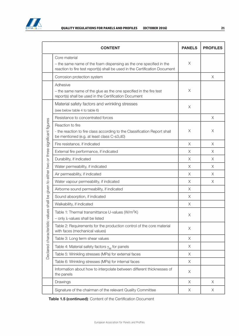
1.4 Content of the Certification Document
CONTENT PANELS PROFILES
FRO
NT
PAG
E
Manufacturer (name and address) X X
Production plant X X
Panel1/Profile Types1 The criteria, in base of which panels can be organized in relevant families to be part of the same CD are:
- The category of the core material (PUR, MW, EPS etc.);
- The face material (e.g. steel, aluminium);
- The plant, if there are different plants producing the same product.
X X
Date of issuing X X
Date of expiry X X
Certification Number(s) – The Quality Label EPAQ shall be used only in combination with this certification number(s).
X X
Number of pages contained X X
Rule for awarding the Quality Certificate and the Quality Label EPAQ:
“This Certification Document is only valid in combination with the valid accompanying Quality Certificate. The Quality Certificate is awarded only after the first external quality control, if the requirements of this Certification Document are fulfilled.”
X X
General X X
Panel/Profile1 types and definition of used materials X X
1 The manufacturer has to state which profiles are only for decking purposes, because the test for determination of resistance to concen-trated forces is necessary for decking products only.
X
Panel/Profile types X X
Characteristics and composition X X
Deck layers
– the metallic coating has not to be mentioned, because it is defined by the certification documents of the base material;
- used tolerances (e.g. for steel, normal or special tolerances, accor ding to EN 10143);
- the relevant standard for the used coating (e.g. organic coating ac-cording to EN 10169)
X
Sheets (Steel, Aluminium etc.) X
Table 1.5: Content of the Certification Document
QUALITY REGULATIONS FOR PANELS AND PROFILES (OCTOBER 2016) 21
European Association for Panels and Profiles
CONTENT PANELS PROFILES
Core material
– the same name of the foam dispensing as the one specified in the reaction to fire test report(s) shall be used in the Certification Document
X
Corrosion protection system X
Adhesive
– the same name of the glue as the one specified in the fire test report(s) shall be used in the Certification Document
X
Dec
lare
d ch
arac
teris
tic v
alue
s sh
all b
e gi
ven
to e
ither
tw
o or
thre
e si
gnifi
cant
figu
res
Material safety factors and wrinkling stresses (see below table 4 to table 6)
X
Resistance to concentrated forces X
Reaction to fire
- the reaction to fire class according to the Classification Report shall be mentioned (e.g. at least class C-s3,d0)
X X
Fire resistance, if indicated X X
External fire performance, if indicated X X
Durability, if indicated X X
Water permeability, if indicated X X
Air permeability, if indicated X X
Water vapour permeability, if indicated X X
Airborne sound permeability, if indicated X
Sound absorption, if indicated X
Walkability, if indicated X
Table 1: Thermal transmittance U-values (W/m2K)
– only λ-values shall be listedX
Table 2: Requirements for the production control of the core material with faces (mechanical values)
X
Table 3: Long term shear values X
Table 4: Material safety factors γM for panels X
Table 5: Wrinkling stresses (MPa) for external faces X
Table 6: Wrinkling stresses (MPa) for internal faces X
Information about how to interpolate between different thicknesses of the panels
X
Drawings X X
Signature of the chairman of the relevant Quality Committee X X
Table 1.5 (continued): Content of the Certification Document

European Association for Panels and Profiles
22 (OCTOBER 2016) QUALITY REGULATIONS FOR PANELS AND PROFILES

QUALITY REGULATIONS FOR PANELS AND PROFILES (OCTOBER 2016) 23
European Association for Panels and Profiles
2 QUALITY REGULATIONS FOR PANELS
2.1 Requirements for the panel properties
2.1.1 Tensile strength of the panel The threshold value of the tensile strength of the panel is defined to:
– PUR/PIR, EPS/XPS: 0.06 MPa as a characteristic value (5 %-fractile)– For other core materials: 0.03 MPa as a characteristic value (5 %-fractile)
Note: The values are defined by reason of the different handling of durability testing. Known PUR/PIR, EPS/XPS shall be considered
to satisfy the durability requirements without testing (for EPS/XPS only DUR 1 required), see EN 14509. Besides, there is currently
no experience for these core materials with tensile strength less than 0.06 MPa. For other core materials, durability testing is always
required.
2.1.2 Reaction to firePanels must have a minimum class of reaction to fire behaviour of C-s3,d0 and must have a certificate of constancy of performance.
All types of core material of the panel, except MW, shall be tested according to EN ISO 11925-2 on the naked core with the result “pass” for the 30s exposure. Panels that do not pass this requirement cannot receive the Quality Label EPAQ.
2.2 Control of the properties
2.2.1 GeneralThe control of the production of panels is carried out by means of the plant’s own production control and external control in accordance with the following stipulations of these regulations.
The manufacturer must conclude a control agreement with the association in order to bear the Quality Label EPAQ, who for his part must commission the appropriate third parties with the control task, in order to be able to observe the requirements in accordance with the Quality Regulations.
After ensuring that the third party fulfils the requirements according to chapter 1, the association has to make a contract with the third party chosen by the manufacturer to ensure that the quality assurance will be based on these regulations.
The implementation of the inspections and the type of documentation are regulated by the Quality Commit-tee for Panels, in agreement with the third parties which carry out the external control.
The reports of assessment and EQC shall be retained for at least five years.
The third parties have to have meetings to coordinate their work if required by the association. These mee-tings ought to be held in combination with the meetings of the Quality Committee for Panels.
The third party has to check the components and their ratios of the foam in case of foamed panels. Third parties can compare the FPC records with the results of type testing. For the expertise and the regular checking, the third parties need the code name of the foam and the names of all components.
2.2.2 Base materialIf the finished product manufacturer buys base materials whose characteristics have already been deter-
European Association for Panels and Profiles
24 (OCTOBER 2016) QUALITY REGULATIONS FOR PANELS AND PROFILES
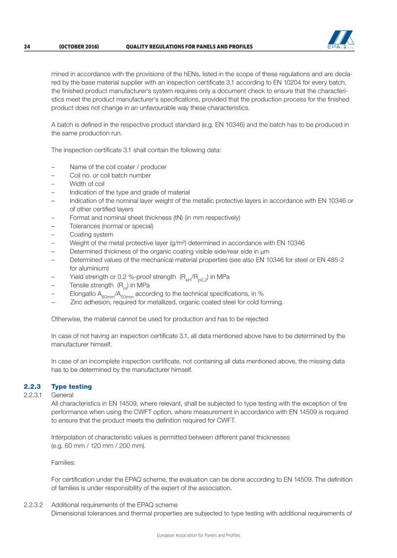
mined in accordance with the provisions of the hENs, listed in the scope of these regulations and are decla-red by the base material supplier with an inspection certificate 3.1 according to EN 10204 for every batch, the finished product manufacturer‘s system requires only a document check to ensure that the characteri-stics meet the product manufacturer‘s specifications, provided that the production process for the finished product does not change in an unfavourable way these characteristics.
A batch is defined in the respective product standard (e.g. EN 10346) and the batch has to be produced in the same production run.
The inspection certificate 3.1 shall contain the following data:
– Name of the coil coater / producer– Coil no. or coil batch number– Width of coil– Indication of the type and grade of material – Indication of the nominal layer weight of the metallic protective layers in accordance with EN 10346 or
of other certified layers– Format and nominal sheet thickness (tN) (in mm respectively) – Tolerances (normal or special)– Coating system– Weight of the metal protective layer (g/m²) determined in accordance with EN 10346– Determined thickness of the organic coating visible side/rear side in μm– Determined values of the mechanical material properties (see also EN 10346 for steel or EN 485-2
for aluminium)– Yield strength or 0,2 %-proof strength (ReH/Rp0,2) in MPa– Tensile strength (Rm) in MPa – Elongatio A80mm/A50mm according to the technical specifications, in %− Zinc adhesion, required for metallized, organic coated steel for cold forming. Otherwise, the material cannot be used for production and has to be rejected
In case of not having an inspection certificate 3.1, all data mentioned above have to be determined by the manufacturer himself.
In case of an incomplete inspection certificate, not containing all data mentioned above, the missing data has to be determined by the manufacturer himself.
2.2.3 Type testing2.2.3.1 General
All characteristics in EN 14509, where relevant, shall be subjected to type testing with the exception of fire performance when using the CWFT option, where measurement in accordance with EN 14509 is required to ensure that the product meets the definition required for CWFT.
Interpolation of characteristic values is permitted between different panel thicknesses (e.g. 60 mm / 120 mm / 200 mm).
Families:
For certification under the EPAQ scheme, the evaluation can be done according to EN 14509. The definition of families is under responsibility of the expert of the association.
2.2.3.2 Additional requirements of the EPAQ schemeDimensional tolerances and thermal properties are subjected to type testing with additional requirements of

QUALITY REGULATIONS FOR PANELS AND PROFILES (OCTOBER 2016) 25
European Association for Panels and Profiles
the European Association for Panels and Profiles, see 2.2.6 and Table 2.3.
2.2.3.3 ResponsibilityThe type testing must be done by third parties for testing according to 1.2.2.2. The evaluation and prepa-ration of the evaluation report must be done by third parties for evaluation and assessment according to 1.2.2.3.
2.2.3.4 Type testingThe type testing can be done in a laboratory or in a factory of the manufacturer. The presence of an inde-pendent representative of a third party is absolutely necessary for calibration and supervision of the tests.
2.2.4 Initial Inspection and External Quality Control2.2.4.1 General
When an initial inspection is necessary, it shall be conducted prior to the first EQC. During the initial inspec-tion, the responsible third party has to inspect the production equipment, the storerooms for raw materials including the tanks for chemicals and the FPC of the manufacturer including the laboratory.
The regular inspection including audit-testing of samples is carried out at least twice a year in the factory of the quality label user based on the control agreement.
2.2.4.2 Responsibility The initial inspection must be done by third parties for evaluation and assessment according to 1.2.2.3 and the EQC tests must be done by third parties for testing according to 1.2.2.2.
2.2.4.3 ProceduresThe EQC needs to be conducted in accordance with the testing regime described in Table 2.4. Sampling and testing have to be done by a third party or can be done by the manufacturer in the presence and under the responsibility of a third party.
– Per date of EQC and certification document, samples of one panel type (one combination of face geometry, one core type and one panel thickness) shall be taken out of running production by the third party. The taken panel types shall be varied in the course of time, to cover the range of producti-on (including also roofs and walls, if relevant) and scope of the certification document.
– An EQC of one manufacturer can be valid for both main applications (walls and roofs), for all types of face geometries, for all types of core material within the same category (e.g. all types of MW, all densities of PUR etc.), even though there are different certification documents.
– The panels for controlling should be taken out of the running production by the third party.
If third parties observe that certified products were not produced during the whole 3 year period of validity, they have to report these types of problems to the Quality Committee for Panels.
In each panel production plant, the internal FPC must be confirmed by EQC at least twice a year. The responsible third party shall be physically present in the plant twice a year. The manufacturer has to put at disposal of the third party all the individual values of its FPC.
The results of the external control are recorded in the test report, in the evaluation report and in the assess-ment report for EQC of the third party. The manufacturer and the secretariat of the association simulta-neously receive one copy of the reports.
Checking of the evaluation of the results within EQC is a task of the Quality Committee for Panels.
In case of inadequate test results within the framework of the external control, the responsible third party must request the manufacturer to adopt appropriate measures to correct the deviations found. If the devia-tions are not corrected within the agreed time period, then the third party must inform the Quality Commit-

European Association for Panels and Profiles
26 (OCTOBER 2016) QUALITY REGULATIONS FOR PANELS AND PROFILES
tee for Panels, which has to decide upon further actions.
The time period within which the manufacturers shall react and report differs based on the severity of the deviations:
Six months or until the following EQC, in cases of marginal deviations, which do not affect the effectiveness of the FPC, respectively the product quality or which could even show a higher quality, although the EQC measurements are outside of the tolerances given in the CD;
Two months, in cases of deviations of medium severity, which affect the product quality only on characteri-stics of less importance so that there is no direct implication on the quality of the product or which affect the effectiveness of the FPC in such a way, that the general function and efficiency still exist;
Immediately, in cases of severe deviations, which affect considerably the effectiveness of the FPC and/or the product quality on major characteristics. In these cases, the secretariat of PPA-Europe and the Quality Committee for Panels have to be informed immediately as to discuss the withdrawal of the EPAQ Quality Certificate.
In cases of severe deviations and deviations of medium severity, the responsible third party must check whether the manufacturer has solved the non-conformities or not and the outcome of the measures adop-ted by the manufacturer shall be included in the EQC reports. The EQC results then shall be either “require-ments fulfilled” or “requirements not fulfilled”.
The check by the responsible third party of the measures to correct marginal deviations can be performed during the next EQC. An extra visit in beforehand is not demandable. The outcome of the measures to cor-rect marginal deviations can be included into the EQC reports or can be handled in a separate report. After checking the outcome, the initial EQC results „requirements fulfilled with comments“ can be either kept or converted into „requirements fulfilled“.
When the outcome of two consecutive external quality controls is negative (the requirements of the CD are not fulfilled), the certification is cancelled and the Quality Label EPAQ is withdrawn.
2.2.4.4 Evaluation of test results for mechanical propertiesNo individual test result in EQC shall be less than the value declared. Otherwise, additional samples need to be taken, tested and the 5 %-fractile value needs to be determined anew. The resulting characteristic value shall not be less than the declared value. Otherwise, the panel loses conformity with the quality label. For the anew determination of the 5%-fractile value, it may be assumed that k = 1,65.
2.2.4.5 Evaluation of test results for other propertiesNo individual test result in EQC shall be less than the value declared. Otherwise, additional samples need to be tested.
2.2.4.6 Thermal insulation performanceThe control of the thermal insulation performance has to be performed with respect to 2.2.6. In case of prefabricated core materials, the control can also be the task of the manufacturer of the core material.
2.2.5 FPC procedures2.2.5.1 General
The manufacturer shall establish procedures to ensure that the stated values of all of the characteristics are maintained in accordance with EN 14509. Table 2.4 shows the test methods which must be used for FPC and external control, the number of specimens and the frequency of FPC and external control.

QUALITY REGULATIONS FOR PANELS AND PROFILES (OCTOBER 2016) 27
European Association for Panels and Profiles
2.2.5.2 FPC for safety in fire characteristicsFPC for safety in fire characteristics shall be carried out according to EN 14509.
2.2.6 Type testing, EQC and FPC procedures for the thermal characteristics2.2.6.1 Determination of the thermal conductivity based on EN 14509
The declared thermal conductivity (λDeclared) shall be determined in accordance with the procedures de-scribed in the appropriate product standard for the core material in the direction used for insulation in the sandwich panel. For preformed CE-marked mineral wool core materials, the values and the results from the manufacturer of the core material can be used without any further testing, if the manufacturer has a quality system that respects the requirements of EN 13172, the CE markings provide the λ values for the orienta-tion used in the panel manufacturing process and these core material performances are controlled under responsibility of a third party, in AVCP system 1+ (EPAQ system A of PPA-Europe). Nevertheless, an external third party control for panels must be done. For other materials than core materials (e.g. metal sheets), tabulated values in accordance with EN 10456 shall be used.
The declared thermal conductivity (λDeclared) and the design value of the thermal conductivity (λDesign) shall be determined. In case of aged values, λDeclared is equal to λDesign (if not stated otherwise). Afterwards, the ther-mal transmittance value (Uds) for the panel system excluding the transversal joints, but taking into account the effects of the longitudinal joints, shall be calculated according to EN 14509. Above note that λDesign is a national choice.
Basic testing / Type testing
Manufacturer: testing 4 samples of different batches
Accepted notified (test) laboratory1): tes-ting 4 samples of the same batches as the manufacturer
Manufacturer: additional testing of minimum 6 samples from other batches
The independent expert for thermal characteristics compares the test results and then con-ducts the statistical evaluation considering the values of type testing from the manufacturer and the accepted notified (test) laboratory1)
λDeclared
1) Accepted by PPA-Europe for thermal conductivity testing; as there are no notified bodies for thermal characteristics in case of EN 14509, the tests can be performed by notified bodies for testing the thermal conductivity of PU according to EN 13165, of MW according to EN 13162, of EPS according to EN 13163 or of XPS according to EN 13164, from the list of third parties accepted by PPA-Europe for thermal conductivi-ty testing.
Figure 2.1. Flow chart of thermal conductivity determination
2.2.6.2 Procedure for panels with PUR coreThe method according to the “fixed increment procedure” shall be used (for core material with CO2 as pro-
European Association for Panels and Profiles
28 (OCTOBER 2016) QUALITY REGULATIONS FOR PANELS AND PROFILES
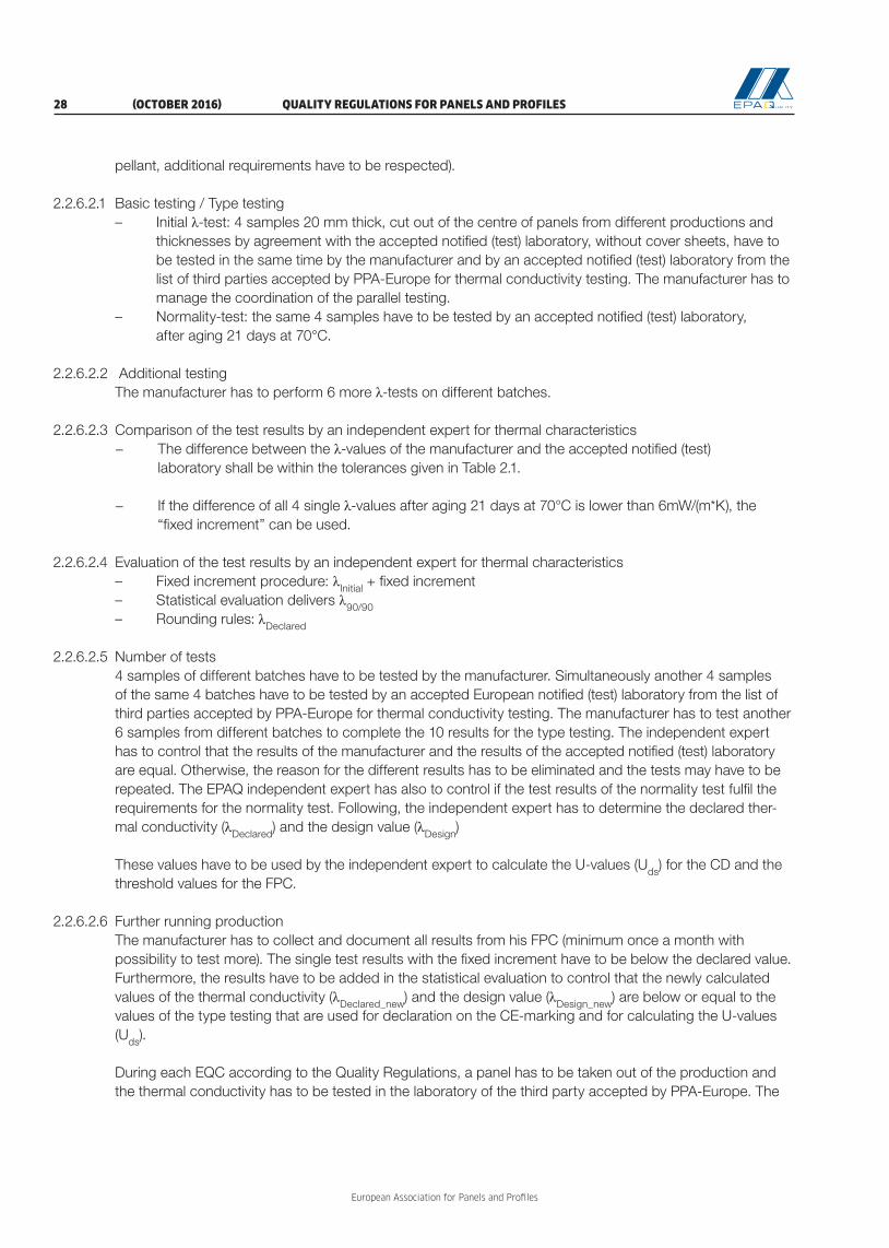
pellant, additional requirements have to be respected).
2.2.6.2.1 Basic testing / Type testing– Initial λ-test: 4 samples 20 mm thick, cut out of the centre of panels from different productions and
thicknesses by agreement with the accepted notified (test) laboratory, without cover sheets, have to be tested in the same time by the manufacturer and by an accepted notified (test) laboratory from the list of third parties accepted by PPA-Europe for thermal conductivity testing. The manufacturer has to manage the coordination of the parallel testing.
– Normality-test: the same 4 samples have to be tested by an accepted notified (test) laboratory, after aging 21 days at 70°C.
2.2.6.2.2 Additional testingThe manufacturer has to perform 6 more λ-tests on different batches.
2.2.6.2.3 Comparison of the test results by an independent expert for thermal characteristics− The difference between the λ-values of the manufacturer and the accepted notified (test) laboratory shall be within the tolerances given in Table 2.1.
− If the difference of all 4 single λ-values after aging 21 days at 70°C is lower than 6mW/(m*K), the “fixed increment” can be used.
2.2.6.2.4 Evaluation of the test results by an independent expert for thermal characteristics– Fixed increment procedure: λInitial + fixed increment– Statistical evaluation delivers λ90/90– Rounding rules: λDeclared
2.2.6.2.5 Number of tests4 samples of different batches have to be tested by the manufacturer. Simultaneously another 4 samples of the same 4 batches have to be tested by an accepted European notified (test) laboratory from the list of third parties accepted by PPA-Europe for thermal conductivity testing. The manufacturer has to test another 6 samples from different batches to complete the 10 results for the type testing. The independent expert has to control that the results of the manufacturer and the results of the accepted notified (test) laboratory are equal. Otherwise, the reason for the different results has to be eliminated and the tests may have to be repeated. The EPAQ independent expert has also to control if the test results of the normality test fulfil the requirements for the normality test. Following, the independent expert has to determine the declared ther-mal conductivity (λDeclared) and the design value (λDesign) These values have to be used by the independent expert to calculate the U-values (Uds) for the CD and the threshold values for the FPC.
2.2.6.2.6 Further running productionThe manufacturer has to collect and document all results from his FPC (minimum once a month with possibility to test more). The single test results with the fixed increment have to be below the declared value. Furthermore, the results have to be added in the statistical evaluation to control that the newly calculated values of the thermal conductivity (λDeclared_new) and the design value (λDesign_new) are below or equal to the values of the type testing that are used for declaration on the CE-marking and for calculating the U-values (Uds).
During each EQC according to the Quality Regulations, a panel has to be taken out of the production and the thermal conductivity has to be tested in the laboratory of the third party accepted by PPA-Europe. The
QUALITY REGULATIONS FOR PANELS AND PROFILES (OCTOBER 2016) 29
European Association for Panels and Profiles
single test results with the fixed increment have to be below or equal to the declared value, otherwise, the reason for the deviation has to be cleared and the tests have to be repeated or the declared values have to be changed. Furthermore, the results have to be added in the statistical evaluation to control that the newly calculated values of the thermal conductivity (λDeclared_new) and the design value (λDesign_new) are below or equal to the values of the type testing that are used for declaration on the CE-marking and for calculating the U-values (Uds).
If the test results of the manufacturer and/or the accepted notified (test) laboratory show permanent devi- tation from the declared thermal conductivity, the declared and design values as well as the U-values (Uds) have to be adjusted in the CD by an independent expert for thermal conductivity.
2.2.6.3 Procedure for panels with MW or EPS core
2.2.6.3.1 Basic testing / Type testing4 samples 50 mm thick or thicker (20 mm thick in case 50 mm is not applicable for the manufacturer), cut out of the centre of panels from different productions and thicknesses, without cover sheets or lamellas taken out before bonding with the steel sheets, have to be tested in the same time by the manufacturer and by an accepted notified (test) laboratory from the list of third parties accepted by PPA-Europe for thermal conductivity testing. The manufacturer has to manage the coordination of the parallel testing. Samples from MW slabs must be cut in such way so that they correspond to lamellas; the cutting direction (line direction or transversal direction) has to be noticed, because thermal conductivity is different.
2.2.6.3.2 Additional testingThe manufacturer has to perform 6 more λ-tests on different batches.
2.2.6.3.3 Comparison of the test results by an independent expert for thermal characteristicsThe difference between the λ-values of the manufacturer and the accepted notified (test) laboratory shall be within the tolerances given in Table 2.1.
2.2.6.3.4 Evaluation of the test results by an independent expert for thermal characteristics– Statistical evaluation delivers λ90/90– Rounding rules: λ Declared λDeclared
2.2.6.3.5 Number of tests4 samples of different batches have to be tested by the manufacturer. Simultaneously another 4 samples of the same 4 batches have to be tested by an accepted European notified (test) laboratory from the list of third parties accepted by PPA-Europe for thermal conductivity testing. The manufacturer has to test another 6 samples from different batches to complete the 10 results for the type testing. The independent expert has to control that the results of the manufacturer and the results of the accepted notified (test) laboratory are equal. Otherwise, the reason for the different results has to be eliminated and the tests may have to be repeated. Following, the independent expert has to determine the declared thermal conductivity (λDeclared) and the design value (λDesign).
These values have to be used by the independent expert to calculate the U-values (Uds) for the CD and the threshold values for the FPC.
In case the tests for thermal conductivity are performed by the manufacturer of the MW, the manufacturer of the MW has to be involved in the basic testing and has also to test 4 samples of the same batches as the accepted notified (test) laboratory and as or instead of the panel manufacturer. The manufacturer of the MW has to follow the regulation of EN 13172.

European Association for Panels and Profiles
30 (OCTOBER 2016) QUALITY REGULATIONS FOR PANELS AND PROFILES
2.2.6.3.6 Further running productionThe panel manufacturer has to collect and document all results from his FPC (minimum once a month with possibility to test more). The single test results have to be below the declared value. Furthermore, the results have to be added in the statistical evaluation to control that the newly calculated values of the thermal con-ductivity (λDeclared_new) and the design value (λDesign_new) are below or equal to the values of the type testing that are used for declaration on the CE-marking and for calculating the U-values (Uds).
During each EQC according to the Quality Regulations, a panel has to be taken out of the production and the thermal conductivity has to be tested in the laboratory of a third party accepted by PPA-Europe. The single test results have to be below the declared value, otherwise, the reason for the deviation has to be cle-ared and the tests have to be repeated or the declared values have to be changed. Furthermore, the results have to be added in the statistical evaluation to control that the newly calculated values of the thermal con-ductivity (λDeclared_new) and the design value (λDesign_new) are below or equal to the values of the type testing that are used for declaration on the CE-marking and for calculating the U-values (Uds). If the test results of the manufacturer and/or the accepted notified (test) laboratory show permanent deviation from the declared thermal conductivity, the declared and design values as well as the U-values (Uds) have to be adjusted in the CD by an independent expert for thermal conductivity.
Core
materialType of produc-
tionsingle- / mean-
λ-valuesMaximum deviation allowed (%)
MW continuouss 7,5
m 5
PUR
continuouss 5
m 3
discontinuouss 7,5
m 5
Others discontinuouss 5
m 3
Table 2.1: Maximum deviation allowed between λ-values obtained by the manufacturer and by the accepted notified (test) laboratory

QUALITY REGULATIONS FOR PANELS AND PROFILES (OCTOBER 2016) 31
European Association for Panels and Profiles
2.3 Additional information for panels 2.3.1. Values under control / needed for different applications of panels
No. Type of test External walls
Internal walls
Cei-lings Roofs
1 Density of core material yes yes yes yes2 Cross-panel tensile strength (with faces) yes yes yes yes3 Thickness of core yes yes yes yes4 Mass of panel yes yes yes yes5 Compressive strength of core material yes yes yes yes6 Shear strength and modulus of core material yes yes yes yes7 Long term shear strength no no yes yes8 Creep coefficient no no yes yes9 Tensile strength and thickness of face material (or declaration) yes yes yes yes
10
yes yes yes yesyes * * yes
yes yes yes yesyes * * yesyes yes yes yesyes * * yes
yes yes yes yesyes yes yes yes
11 Dimensional tolerances yes yes yes yes12 Resistance to point and access loads n.a. n.a. yes yes13 Reaction to fire - certification yes yes yes yes14 Durability yes * n.a. yes15 Long term effects n.a. n.a. yes yes16 External fire performance – certification n.a. n.a. n.a. yes17 Thermal insulation performance yes * * yes*: optional n.a.: not applicable Optional: if declared, then under control
18
Bending resistance in span and at internal support:
- positive bending, elevated temperature
- negative bending, elevated temperature
Wrinkling stresses:
- wrinkling stress, internal face:
- in span, elevated temperature
- at internal central support, elevated temp.
yes
yes
yes
yes
yes
yes
yes
yes
yes
yes
19 Resistance to fire – certification yes20 Thermal insulation performance yes21 Water permeability yes22 Air permeability yes23 Airborne sound insulation yes24 Sound absorption yes25 Durability yes26 Long term effects yes
Table 2.2: Values under control / needed for different applications of panels
Bending resistance in span and at internal support:- positive bending- negative bendingWrinkling stresses:- wrinkling stress, external face:- in span- in span, elevated temperature- at internal central support- at internal central support, elevated temp.- wrinkling stress, internal face:- in span
- at internal central support
European Association for Panels and Profiles
32 (OCTOBER 2016) QUALITY REGULATIONS FOR PANELS AND PROFILES
2.3
.1
2
.3.2
2
.3.2
Dim
en
sion
al to
lera
nces,
test
sp
ecim
en
s, t
ype o
f th
e t
est
an
d t
ype t
est
ing c
on
dit
ion
s fo
r p
an
els
Dim
ensi
on
al t
ole
ran
ces
Fig
ure
Test
m
eth
od
Typ
e o
f te
stC
om
plia
nce
cri
teri
a an
d
spec
ific
con
dit
ion
s
EN 1
4509
: A
nnex
DTy
pe te
stin
g
Valu
es o
f EN
145
09N
ew v
alue
s ac
cord
ing
to th
e EP
AQ
sch
eme
Thic
knes
s of
the
pane
l2.
2D
.2.1
D ≤
100
mm
± 2
mm
D
> 1
00 m
m ±
2 %
Dev
iatio
n fro
m fl
atne
ss (a
ccor
ding
to
the
leng
th o
f mea
sure
men
t L)
2.3
D.2
.2
L [m
m]
200
40
0 ≥7
00
Max
. dev
iatio
n fro
m fl
atne
ss [m
m]:
0,
6
1,0
1,5
L [m
m]
≤200
400
≥700
Max
. dev
iatio
n fro
m fl
atne
ss [m
m]:
0,
4
0,7
1,0
Inte
rmed
iate
val
ues
may
be
inte
rpol
ated
Dep
th o
f met
al p
rofil
e2.
4D
.2.3
5 m
m
< h
≤ 5
0 m
m
± 1
mm
50 m
m <
h ≤
100
mm
±
2,5
mm
Dep
th o
f stif
fene
rs o
n lig
htly
pro
filed
face
s2.
5D
.2.4
d s ≤ 1
mm
± 3
0 %
von
ds
1 m
m <
ds ≤
3 m
m
± 0
,3 m
m
3 m
m <
ds ≤
5 m
m
± 1
0 %
of d
s
Com
plia
nce
has
to b
e pr
oofe
d on
ly b
y a
mea
surin
g ru
le a
nd a
pre
cisi
on g
auge
.
Leng
th o
f the
pan
el2.
6 an
d 2.
7D
.2.5
L ≤
3000
mm
± 5
mm
L >
300
0 m
m
±
10
mm
L <
6 m
: 5
mm
L
> 1
2 m
: ± 1
0 m
mIn
term
edia
te v
alue
s m
ay b
e in
terp
olat
ed
Cov
er w
idth
of t
he p
anel
2.8
÷ 2
.11
D.2
.6±
2 m
m
Dev
iatio
n fro
m s
quar
enes
s2.
12D
.2.7
s ≤
0,00
6 x
w
0,00
6 x
w (r
oof)
0,
004
x w
(wal
l)
Dev
iatio
n fro
m s
trai
ghtn
ess
(on
leng
th)
2.13
D.2
.81,
0 m
m /
m n
ot e
xcee
ding
5 m
m
Bow
ing
(cur
vatu
re o
n le
ngth
or
wid
th)
2.14
D.2
.9
2,0
mm
/ (m
eng
th) ≤
10
mm
8,5
mm
/ (m
wid
th fo
r fla
t pro
files
, h ≤
10
mm
)
10,0
mm
/ (m
wid
th fo
r ot
her
dept
h, h
> 1
0 m
m)
Pitc
h of
the
profi
le2.
15, 2
.16
D.2
.10
h ≤
50 m
m
± 2
mm
h >
50
mm
±
3 m
m±
1,5
mm
Tab
le 2
.3: D
imen
sion
al to
lera
nces
, tes
t spe
cim
ens,
typ
e of
the
test
and
typ
e te
stin
g co
nditi
ons
for
pane
ls
QUALITY REGULATIONS FOR PANELS AND PROFILES (OCTOBER 2016) 33
European Association for Panels and Profiles
2.3
.1
2
.3.2
2
.3.2
Dim
en
sion
al to
lera
nces,
test
sp
ecim
en
s, t
ype o
f th
e t
est
an
d t
ype t
est
ing c
on
dit
ion
s fo
r p
an
els
Dim
ensi
on
al t
ole
ran
ces
Fig
ure
Test
m
eth
od
Typ
e o
f te
stC
om
plia
nce
cri
teri
a an
d
spec
ific
con
dit
ion
s
EN 1
4509
: A
nnex
DTy
pe te
stin
g
Valu
es o
f EN
145
09N
ew v
alue
s ac
cord
ing
to th
e EP
AQ
sch
eme
Thic
knes
s of
the
pane
l2.
2D
.2.1
D ≤
100
mm
± 2
mm
D
> 1
00 m
m ±
2 %
Dev
iatio
n fro
m fl
atne
ss (a
ccor
ding
to
the
leng
th o
f mea
sure
men
t L)
2.3
D.2
.2
L [m
m]
200
40
0 ≥7
00
Max
. dev
iatio
n fro
m fl
atne
ss [m
m]:
0,
6
1,0
1,5
L [m
m]
≤200
400
≥700
Max
. dev
iatio
n fro
m fl
atne
ss [m
m]:
0,
4
0,7
1,0
Inte
rmed
iate
val
ues
may
be
inte
rpol
ated
Dep
th o
f met
al p
rofil
e2.
4D
.2.3
5 m
m
< h
≤ 5
0 m
m
± 1
mm
50 m
m <
h ≤
100
mm
±
2,5
mm
Dep
th o
f stif
fene
rs o
n lig
htly
pro
filed
face
s2.
5D
.2.4
d s ≤ 1
mm
± 3
0 %
von
ds
1 m
m <
ds ≤
3 m
m
± 0
,3 m
m
3 m
m <
ds ≤
5 m
m
± 1
0 %
of d
s
Com
plia
nce
has
to b
e pr
oofe
d on
ly b
y a
mea
surin
g ru
le a
nd a
pre
cisi
on g
auge
.
Leng
th o
f the
pan
el2.
6 an
d 2.
7D
.2.5
L ≤
3000
mm
± 5
mm
L >
300
0 m
m
±
10
mm
L <
6 m
: 5
mm
L
> 1
2 m
: ± 1
0 m
mIn
term
edia
te v
alue
s m
ay b
e in
terp
olat
ed
Cov
er w
idth
of t
he p
anel
2.8
÷ 2
.11
D.2
.6±
2 m
m
Dev
iatio
n fro
m s
quar
enes
s2.
12D
.2.7
s ≤
0,00
6 x
w
0,00
6 x
w (r
oof)
0,
004
x w
(wal
l)
Dev
iatio
n fro
m s
trai
ghtn
ess
(on
leng
th)
2.13
D.2
.81,
0 m
m /
m n
ot e
xcee
ding
5 m
m
Bow
ing
(cur
vatu
re o
n le
ngth
or
wid
th)
2.14
D.2
.9
2,0
mm
/ (m
eng
th) ≤
10
mm
8,5
mm
/ (m
wid
th fo
r fla
t pro
files
, h ≤
10
mm
)
10,0
mm
/ (m
wid
th fo
r ot
her
dept
h, h
> 1
0 m
m)
Pitc
h of
the
profi
le2.
15, 2
.16
D.2
.10
h ≤
50 m
m
± 2
mm
h >
50
mm
±
3 m
m±
1,5
mm
Tab
le 2
.3: D
imen
sion
al to
lera
nces
, tes
t spe
cim
ens,
typ
e of
the
test
and
typ
e te
stin
g co
nditi
ons
for
pane
ls
Dim
ensi
on
al t
ole
ran
ces
Fig
ure
Test
m
eth
od
Typ
e o
f te
stC
om
plia
nce
cri
teri
a an
d
spec
ific
con
dit
ion
s
Wid
th o
f the
rib
s (b
1) and
Wid
th o
f the
val
leys
(b2)
2.17
D.2
.11
R
ibs:
±
1 m
m
V
alle
ys:
± 2
mm
Alig
nmen
t
2.18
EPA
Q
sche
me
-
Δe
≤ 3
mm
Δe:
diff
eren
ce (o
verla
ppin
g) b
etw
een
inne
r an
d ou
ter
shee
t at t
he jo
int (
Ieo -
eUI)
(The
refe
renc
e po
int o
f eu a
nd e
o has
to b
e ad
apte
d to
the
indi
vidu
al g
eom
etry
und
er
resp
onsi
bilit
y of
the
third
par
ty)
Diff
eren
ce in
mea
sure
d th
ickn
ess
of jo
int
-Δ
D ≤
2 m
m
ΔD
: diff
eren
ce o
f the
pan
el th
ickn
esse
s D
right
an
d D
left a
t the
bot
h ed
ges
Long
itudi
nal e
dge
leng
th
2.19
-h u
≥ 10
mm
Edge
wav
ines
s-
W =
± 2
mm
ove
r 50
0 m
m le
ngth
Tab
le 2
.3 (c
on
tin
ued
): D
imen
sion
al to
lera
nces
, tes
t spe
cim
ens,
typ
e of
the
test
and
typ
e te
stin
g co
nditi
ons
for
pane
ls

European Association for Panels and Profiles
34 (OCTOBER 2016) QUALITY REGULATIONS FOR PANELS AND PROFILES
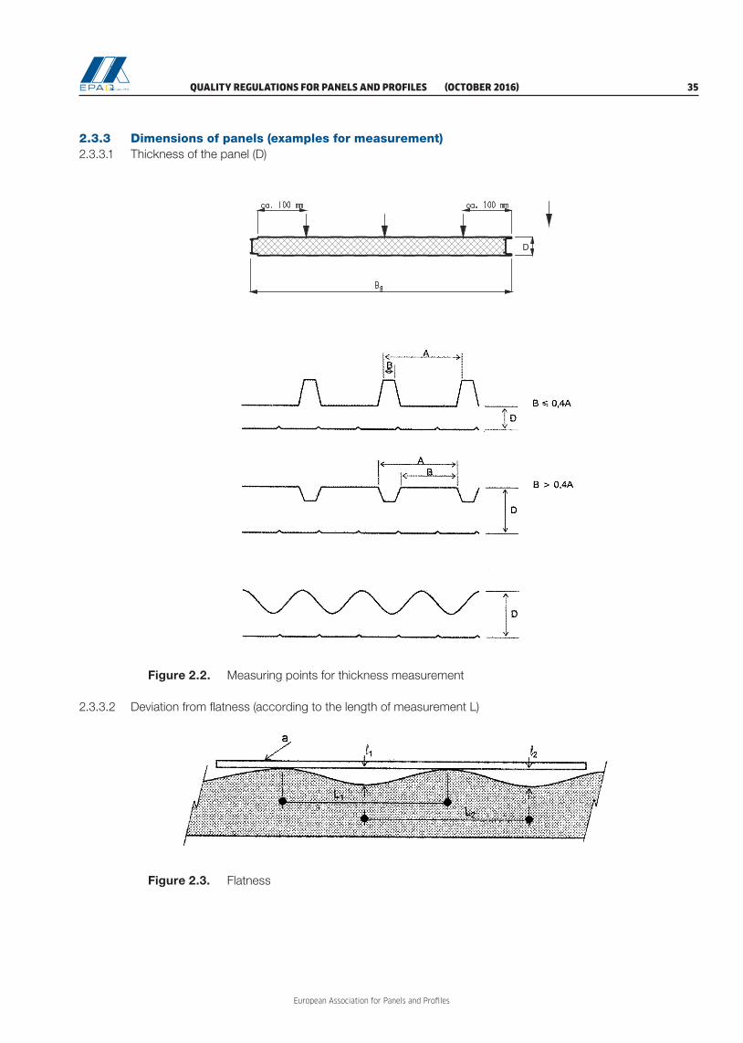
QUALITY REGULATIONS FOR PANELS AND PROFILES (OCTOBER 2016) 35
European Association for Panels and Profiles
Figure 2.3. Flatness
2.3.3 Dimensions of panels (examples for measurement)2.3.3.1 Thickness of the panel (D)
D
D
eo
hto
dhtu
eu
Figure 2.2. Measuring points for thickness measurement
2.3.3.2 Deviation from flatness (according to the length of measurement L)

European Association for Panels and Profiles
36 (OCTOBER 2016) QUALITY REGULATIONS FOR PANELS AND PROFILES
2.3.3.3 Depth of metal profile (h)
Figure 2.4. Dimensional check for depth of profile h
2.3.3.4 Depth of stiffeners on lightly profiled faces (ds)
Figure 2.5. Depth of stiffeners and light profiling
2.3.3.5 Length of the panel (L)
Figure 2.6. Length (measurement on a roof panel, on the center rib)
c/l – center line of the panel

QUALITY REGULATIONS FOR PANELS AND PROFILES (OCTOBER 2016) 37
European Association for Panels and Profiles
L
(m
m)
Figure 2.7. Length (measurement on a roof panel, on the center valley)
2.3.3.6 Cover width of the panel (w)
Figure 2.8. Cover width (w) of profiled panels

European Association for Panels and Profiles
38 (OCTOBER 2016) QUALITY REGULATIONS FOR PANELS AND PROFILES
Figure 2.9. Cover width (w) in case of male-female joint
Figure 2.10. Measurement of cover width (w)
Figure 2.11. Dimensional check for cover width w and pitch p using a calibrated gauge

QUALITY REGULATIONS FOR PANELS AND PROFILES (OCTOBER 2016) 39
European Association for Panels and Profiles
2.3.3.7 Deviation from squareness (s)
Figure 2.12. Squareness
2.3.3.8 Deviation from straightness - on length
Figure 2.13. Deviation of straightness
2.3.3.9 Bowing or curvature on length or width (b)
Figure 2.14. Panel bowing

European Association for Panels and Profiles
40 (OCTOBER 2016) QUALITY REGULATIONS FOR PANELS AND PROFILES
2.3.3.10 Pitch of the profile (p)
Figure 2.15. Pitch (p)
Figure 2.16. Dimensional check for pitch
2.3.3.11 Width of the ribs (b1) and width of the valleys (b2)
Figure 2.17. Widths of rib and valley

QUALITY REGULATIONS FOR PANELS AND PROFILES (OCTOBER 2016) 41
European Association for Panels and Profiles
2.3.3.12 Alignment and difference in measured thickness of joint
Figure 2.18. Alignment and difference in measured thickness of joint
2.3.3.13 Longitudinal edge length and edge waviness
A
Detail A:
Figure 2.19. Edge waviness
a b W
W W W

European Association for Panels and Profiles
42 (OCTOBER 2016) QUALITY REGULATIONS FOR PANELS AND PROFILES
2.3.4 FPC and external control procedures for panels
Type of test
Test method
(EN 14509 / EPAQ
scheme )
FPC
External control twice a
year
Mini-mum
number of speci-
mens
Minimum frequency
Number of specimens
Density of core material A.8 31 per shift/ 6 or 8ha 6
Cross-panel tensile strength and modulus (with faces) A.1 31 per shift/
6 or 8ha 10
Compressive strength and modulus of core material A.2 31
per weeka 10
Shear strength and modulus of core materiale A.3 31
per weeka 10
Tensile strength of face material (or declaration – 2.2.2.) - 3All
deliveries3
Thickness of face material (or declaration – 2.2.2.) - 3All
deliveries3
Shear strength and modulus of the core material based on the testing of a complete panelb
A.4 11
per 2 weeksa
1
Wrinkling stress (optional see Note 3) A.5 11
per weeka 1
Dimensional control:
Panel thickness
Deviation from flatness
Depth of profile
Depth of stiffeners
Length of panel
Cover width
Deviation from squareness
Deviation from straightness
Bowing (curvature)
Pitch of profile
Width of valleys/ribs
Alignement
Difference in measured thickness of joint
Longitudinal edge length
Edge waviness
D.2.1
D.2.2
D.2.3
D.2.4
D.2.5
D.2.6
D.2.7
D.2.8
D.2.9
D.2.10
D.2.11
EPAQ
EPAQ
EPAQ
EPAQ
11 per shift/
6 or 8h1
Reaction to fire – certification (EN 14509, 6.3.5.3)c C.1.2.2 a) 1 Satz 1/week
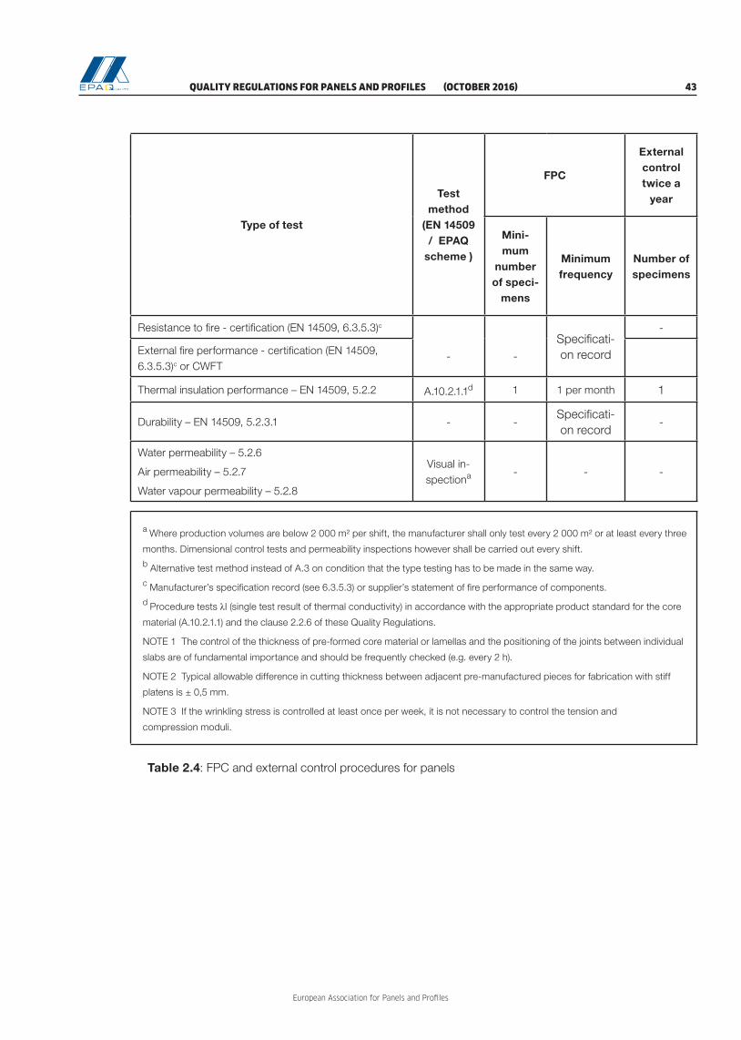
QUALITY REGULATIONS FOR PANELS AND PROFILES (OCTOBER 2016) 43
European Association for Panels and Profiles
Type of test
Test method
(EN 14509 / EPAQ
scheme )
FPC
External control twice a
year
Mini-mum
number of speci-
mens
Minimum frequency
Number of specimens
Resistance to fire - certification (EN 14509, 6.3.5.3)c
- -Specificati-on record
-
External fire performance - certification (EN 14509, 6.3.5.3)c or CWFT
Thermal insulation performance – EN 14509, 5.2.2 A.10.2.1.1d 1 1 per month 1
Durability – EN 14509, 5.2.3.1 - -Specificati-on record
-
Water permeability – 5.2.6
Air permeability – 5.2.7
Water vapour permeability – 5.2.8
Visual in-spectiona - - -
a Where production volumes are below 2 000 m² per shift, the manufacturer shall only test every 2 000 m² or at least every three
months. Dimensional control tests and permeability inspections however shall be carried out every shift.
b Alternative test method instead of A.3 on condition that the type testing has to be made in the same way.
c Manufacturer’s specification record (see 6.3.5.3) or supplier’s statement of fire performance of components.
d Procedure tests λI (single test result of thermal conductivity) in accordance with the appropriate product standard for the core
material (A.10.2.1.1) and the clause 2.2.6 of these Quality Regulations.
NOTE 1 The control of the thickness of pre-formed core material or lamellas and the positioning of the joints between individual
slabs are of fundamental importance and should be frequently checked (e.g. every 2 h).
NOTE 2 Typical allowable difference in cutting thickness between adjacent pre-manufactured pieces for fabrication with stiff
platens is ± 0,5 mm.
NOTE 3 If the wrinkling stress is controlled at least once per week, it is not necessary to control the tension and
compression moduli.
Table 2.4: FPC and external control procedures for panels

European Association for Panels and Profiles
44 (OCTOBER 2016) QUALITY REGULATIONS FOR PANELS AND PROFILES

QUALITY REGULATIONS FOR PANELS AND PROFILES (OCTOBER 2016) 45
European Association for Panels and Profiles
3 QUALITY REGULATIONS FOR PROFILES
3.1 Requirements for material properties
3.1.1 Nominal thickness The nominal thickness of the self-supporting metal sheet (excluding any organic, inorganic or multi-layer coating), as defined in the relevant material standards listed in EN 506, EN 508-1, EN 508-2 and EN 508-3, shall be for all applications equal to or greater than:
– Aluminium: 0,7 mm– Stainless steel: 0,7 mm– Steel: 0,6 mm
3.1.2 Reaction to fire Metallic coated steel sheet, profiled or flat, fulfils the requirements regarding reaction to fire under the EPAQ scheme when coated on the surface exposed to the fire with a coating of maximum nominal thickness 200 μm and having a coating mass ≤ 300 g/m2 and a PCS ≤ 7,0 MJ/m2. The steel sheet surface not exposed to the fire may have an organic coating, provided that this coating has a thickness ≤ 15 μm and a PCS ≤ 0,7 MJ/m2. Organic coatings exceeding these limits require a classification according EN 13501-1 and shall have a minimum class of reaction to fire behaviour of C-s3, d0.
3.2 Control of material properties
3.2.1 GeneralThe control of the production of profiles is carried out by means of the plant’s own production control and external control in accordance with the following stipulations of these regulations.
The manufacturer must conclude a control agreement under the EPAQ scheme in order to bear the Quality Label EPAQ, who for his part must commission the appropriate third parties with the control task, in order to be able to observe the requirements in accordance with the Quality Regulations.
After ensuring that the third party fulfils the requirements according to chapter 1, the association has to make a contract with the third party chosen by the manufacturer to ensure that the quality assurance will be based on these regulations.
The implementation of the inspections and the type of documentation are regulated by the Quality Commit-tee for Profiles in agreement with the third parties which carry out the external control.
The reports of assessment and EQC shall be retained for at least five years.
The third parties have to have meetings to coordinate their work if required by the Quality Committee for Profiles. These meetings ought to be held in combination with the meetings of the Quality Committee for Profiles.

European Association for Panels and Profiles
46 (OCTOBER 2016) QUALITY REGULATIONS FOR PANELS AND PROFILES
3.2.2 Base materialIf the finished product manufacturer buys base materials whose characteristics have already been deter-mined in accordance with the provisions of the hENs listed in the scope of these regulations and are decla-red by the base material supplier with an inspection certificate 3.1 according to EN 10204 for every batch, the finished product manufacturer‘s system requires only a document check to ensure that the characteri-stics meet the product manufacturer‘s specifications, provided that the production process for the finished product does not change in an unfavourable way these characteristics. Therefore, the mechanical proper-ties have to be determined on longitudinal direction.
A batch is defined in the respective product standard (e.g. EN 10346) and the batch has to be produced in the same production run.
The inspection certificate 3.1 shall contain the following data:
– Name of the coil coater / producer– Coil no. or coil batch number– Indication of the type and grade of material – Indication of the nominal layer weight of the metallic protective layers in accordance with EN 10346
or of other certified layers– Format and nominal sheet thickness (tN) (in mm respectively) – Coating system– Weight of the metal protective layer (g/m²) determined in accordance with EN 10346– Determined thickness of the organic coating visible side/rear side in μm– Determined values of the mechanical material properties (see also EN 10346 for steel
or EN 485-2 for aluminium)– Yield strength or 0,2 %-proof strength (ReH/Rp0,2) in MPa– Tensile strength (Rm) in MPa – Elongation A80mm / A50mm according to the technical specifications, in %– Zinc adhesion, required for metallized, organic coated steel for cold forming.
Otherwise, the material cannot be used for production and has to be rejected.
In case of not having an inspection certificate 3.1, all data mentioned above have to be determined by the manufacturer himself.
In case of an incomplete inspection certificate, not containing all data mentioned above, the missing data has to be determined by the manufacturer himself.
3.2.3 Type testing3.2.3.1 General
All characteristics in EN 14782 or EN 1090-1, where relevant, shall be subjected to type testing with the exception of fire performance when using the CWFT option, where measurement in accordance with EN 14782 is required to ensure that the product meets the definition required for CWFT.
3.2.3.2 Additional requirements of the European Association for Panels and ProfilesDimensional tolerances are subjected to type testing with additional requirements of the European Associa-tion for Panels and Profiles, see Table 3.3 to 3.9.
3.2.3.3 ResponsibilityThe type testing must be done by third parties for testing according to 1.2.2.2. The evaluation and prepa-ration of the evaluation report must be done by third parties for evaluation and assessment according to 1.2.2.3.
QUALITY REGULATIONS FOR PANELS AND PROFILES (OCTOBER 2016) 47
European Association for Panels and Profiles
3.2.3.4 Type testingThe type testing shall be made in a recognized laboratory. Alternatively, the type testing can be performed in a not-recognized laboratory; in this case, the presence of an independent representative of a third party is mandatory for calibration and supervision of the tests.
3.2.4 Initial Inspection and External Quality Control3.2.4.1 General
When an initial inspection is necessary, it shall be conducted prior to the first EQC.
The EQC including audit-testing of samples is carried out at least once a year in the factory of the quality label user, based on the control agreement.
3.2.4.2 ResponsibilityThe initial inspection must be done by third parties for evaluation and assessment according to 1.2.2.3 and the EQC tests must be done by third parties for testing according to 1.2.2.2.
3.2.4.3 ProceduresThe EQC needs to be conducted in accordance with the testing regime described in Table 3.10 and 3.11. The necessary samples are to be taken from the stock. Sampling and testing have to be done by a third party or can be done by the manufacturer in the presence and under the responsibility of a third party.
In each profile production plant, the internal FPC must be confirmed by EQC at least once a year. The res-ponsible third party shall be physically present in the plant once a year.
The record of the results of the FPC must be submitted to the third party by the manufacturer.
The efficiency of an existing quality management system must be shown by certificate or has to be checked by the third party according to clause 1.2.1.2.
In the case of EQC, samples from the stock must be selected in such a way that all profiles are checked in the course of three years period of validity.
The results of the external control are recorded in the test report, in the evaluation report and in the assess-ment report for EQC of the third party. The manufacturer and the secretariat of the association simulta-neously receive one copy of the reports.
Checking of the evaluation of the results within EQC is a task of the Quality Committee for Profiles.
In case of inadequate test results within the framework of the external control, the responsible third party must request the manufacturer to adopt appropriate measures to correct the deviations found. If the devia-tions are not corrected within the agreed time period, then the third party must inform the Quality Commit-tee for Profiles, which has to decide upon further actions.
The time period within which the manufacturers shall react and report differs based on the severity of the deviations: − Six months or until the following EQC, in cases of marginal deviations, which do not affect the effecti veness of the FPC, respectively the product quality or which could even show a higher quality, although the EQC measurements are outside of the tolerances given in the CD;

European Association for Panels and Profiles
48 (OCTOBER 2016) QUALITY REGULATIONS FOR PANELS AND PROFILES
– Two months, in cases of deviations of medium severity, which affect the product quality only on characteristics of less importance so that there is no direct implication on the quality of the product or which affect the effectiveness of the FPC in such a way, that the general function and efficiency still exist;
– Immediately, in cases of severe deviations, which affect considerably the effectiveness of the FPC and/or the product quality on major characteristics. In these cases, the secretariat of PPA-Europe and the Quality Committee for Profiles have to be informed immediately as to discuss the withdrawal of the EPAQ Quality Certificate.
In cases of severe deviations and deviations of medium severity, the responsible third party must check whether the manufacturer has solved the non-conformities or not and the outcome of the measures adop-ted by the manufacturer shall be included in the EQC reports. The EQC results then shall be either “require-ments fulfilled” or “requirements not fulfilled”.
The check by the responsible third party of the measures to correct marginal deviations can be performed during the next EQC. An extra visit in beforehand is not demandable. The outcome of the measures to cor-rect marginal deviations can be included into the EQC reports or can be handled in a separate report. After checking the outcome, the initial EQC results „requirements fulfilled with comments“ can be either kept or converted into „requirements fulfilled“.
3.2.4.4 Evaluation of test results for mechanical propertiesNo individual test result in EQC shall be less than the value declared. Otherwise, additional samples need to be taken, tested and the 5 %-fractile value needs to be determined anew. The resulting characteristic value shall not be less than the declared value. Otherwise, the profile loses conformity with the quality label. For the anew determination of the 5%-fractile value, it may be assumed that k = 1,65.
3.2.4.5 Evaluation of test results for other propertiesNo individual test result in EQC shall be less than the value declared. Otherwise, additional samples need to be tested.
3.2.5 FPC procedures3.2.5.1 General
The manufacturer shall establish procedures to ensure that the stated values of all of the characteristics are maintained in accordance with EN 14782 or EN 1090-1. EN 14782 or EN 1090-1 show the test methods which must be used for FPC and external control, the number of specimens and the frequency of FPC and external control.
Products according to EN 1090-1 need a certificate of conformity of the FPC prior to the awarding of the Certification Document.
3.2.5.2 FPC for safety in fire characteristicsFPC for safety in fire characteristics shall be carried out according to EN 14782 and EN 1090-1.

QUALITY REGULATIONS FOR PANELS AND PROFILES (OCTOBER 2016) 49
European Association for Panels and Profiles
3.2.6 Measurement of dimensional characteristics3.2.6.1 General
The measurements are carried out in accordance with the FPC and the external control procedures. Additi-onal measurement procedures are provided in the Testing Rules for Profiles
3.2.6.2 MaterialsFor the inspection of the material properties required for the base material, see 3.2.2.
3.2.6.3 Sheet thicknessThe measurement of the steel sheet thickness is carried out in accordance with EN 10143 and indeed prior to the cold forming, see also Table 3.10. In the relevant cases, the special requirements of metal coating have to be considered.
If measurements are made on profiled sheet, then the measurement of the sheet thickness t is carried out at least on 3 measuring points on one end of profile, see 3.4, Figure 3.2, 3.13, 3.23, 3.29 and 3.30. The average value is deemed to be the sheet thickness but no individual value should be beneath the stipulated permissible minus dimension.
3.2.6.4 Trapezoidal profiles3.2.6.4.1 General information
The inspection of the dimensional accuracy of the trapezoidal profiles is carried out on the basis of spot checks in accordance with the following regulations, during the manufacturing process. All the measure-ments are carried out 200 mm away from a profile end, if nothing else is indicated.
3.2.6.4.2 Depth of profile h The distance between the surfaces of the same side of the upper and lower flange is deemed as being the depth of profile h.
The measurement is carried out in accordance with 3.4, Figure 3.4 and 3.5.
3.2.6.4.3 Pitch of the profile pThe pitch of the profile p shall be the distance between the centres of adjacent ribs, measured at 200 mm from sheet ends, see 3.4, Figure 3.10. In case the width of flanges is different, all the different pitches have to be measured..
3.2.6.4.4 Cover width wThe cover width w indicates the modular dimension for the width. It is stated by the manufacturer.
The cover widths w1 and w2 are measured 200 mm from the sheet ends and w3 is measured in the profile centre of an evenly supported structural member, see 3.4, Figure 3.6. For the correct measurement of the cover width, a second sample shall be used to simulate the overlap of two profiles.
3.2.6.4.5 Cover width difference of the profile w3The third measurement w3 of cover width shall be made across the centre line of the sheet (see 3.2.6.4.4) to determine the cover width difference of the profile. This w3 measurement shall be within the stated tolerance referred to the average value for w1 and w2.
3.2.6.4.6 Width of crown and valley The widths of crown and valley b must be measured on all the profile ribs, see 3.4, Figure 3.1.
3.2.6.4.7 Radius of bends r The measurement of the radius is carried out on the inside of the bends in accordance with the positions displayed in 3.4, Figure 3.7.

European Association for Panels and Profiles
50 (OCTOBER 2016) QUALITY REGULATIONS FOR PANELS AND PROFILES
3.2.6.4.8 Position of flange stiffeners bk and depth of flange stiffeners hrThe position bk and the height hr must be measured on all crowns, see 3.4, Figure 3.1.
3.2.6.4.9 Position of web stiffeners ha, hb and depth of stiffeners vsa, vsb
With respect to the position ha, hb, the vertical distance of the start of the web from the external surface of the upper or lower flange applies, see 3.4, Figure 3.1.
The length hsa, hsb, see 3.4, Figure 3.1, is the calculated difference between the vertical distances from the start and end of the web and the external surface of the upper or lower flange that have been measured.
The distance of the neighbouring parallel displaced web surfaces applies as the displacement vsa, vsb, see 3.4, Figure 3.1, measured between the respective sheet external or internal surfaces.
In the case of profiles with sectional differing web inclines, the average value from the two measurements from both sides of the web applies as the displacement.
3.2.6.4.10 Crown curvature he The crown curvature he must be measured on all crowns. In case of crowns with stiffener in the middle, he is obtained by reducing the depth of stiffener measured in beforehand, see 3.4, Figure 3.1.
3.2.6.4.11 Length of the profile l The length of the profile l must be determined on the middle rib on the profile, see 3.4, Figure 3.6.
3.2.6.4.12 Deviation from squareness S The determination of the deviation from squareness S must be controlled in accordance with 3.4, Figure 3.9.
3.2.6.4.13 Longitudinal edge upstand sThe longitudinal edge upstand s is measured on the longitudinal edge, see 3.4, Figure 3.1.
3.2.6.4.14 Deviation of side lap DThe deviation of side lap D is defined in 3.4, Figure 3.3. It is determined by means of the straightness of the longitudinal edge.
3.2.6.4.15 Longitudinal edge width buf In the case of lower profile flange with the transverse bead, the dimension buf must be agreed upon with the third party, otherwise it will be inspected on the basis of the flange widths bu in accordance with the existing formula, see 3.4, Figure 3.1 and Table 3.4.
3.2.6.4.16 Deviation from straightness δThe deviation from straightness δ is measured on the longitudinal edge of a middle rib, see 3.4, Figure 3.8.
3.2.6.4.17 Position and dimension of perforation The position and dimension of perforation of acoustic trapezoidal profiles must be inspected in accordance with 3.4, Figure 3.11.
3.2.6.4.18 Flatness of unstiffened or stiffened flange or web If deviations from flatness in longitudinal direction of the element are visible, then the deviation Δ has to be measured, see 3.4, Figure 3.12.
3.2.6.4.19 Curvature of flange If a curvature of flange is visible, then the deviation Δ has to be measured, according to EN 1090-2.

QUALITY REGULATIONS FOR PANELS AND PROFILES (OCTOBER 2016) 51
European Association for Panels and Profiles
3.2.6.5 Sinusoidal profiles3.2.6.5.1 General information
The inspection of the dimensional accuracy of the sinusoidal profiles is carried out on the basis of spot checks in accordance with the following regulations, during the manufacturing process. All the measure-ments are carried out 200 mm away from a profile end, if nothing else is indicated.
3.2.6.5.2 Depth of profile hThe distance between crowns and valleys is deemed as being the depth of profile h.
The measurement is carried out in accordance with 3.4, Figure 3.14, by means of the application of a mea-suring aid upon the wave high points. The measurement is carried out to the wave trough.
3.2.6.5.3 Pitch of the profile pThe pitch of the profile p shall be the distances between the centres of adjacent waves, measured at 200 mm from sheet ends, see 3.4, Figure 3.15.
3.2.6.5.4 Cover width wThe cover width w indicates the distance of the high points of both external waves.
The cover widths w1 and w2 are measured 200 mm from the profile ends and w3 is measured in the profile centre of an evenly supported structural member respectively. The cover width is determined at the upper side of the profile, see 3.4, Figure 3.16.
3.2.6.5.5 Cover width difference of the profile w3The third measurement w3 of cover width shall be made across the centre line of the sheet (see 3.2.6.5.4) to determine the cover width difference of the profile. This w3 measurement shall be within the stated tolerance referred to the average value for w1 and w2.
3.2.6.5.6 Radius of bends rThe measurement of the radius is carried out at the positions shown in 3.4, Figure 3.17 for each indicated wave on the upper and lower side of the profile by means of radius gauges.
3.2.6.5.7 Deviation from squareness S The determination of the deviation from squareness S must be controlled in accordance with 3.4, Figure 3.19.
3.2.6.5.8 Length of the profile lThe length of the profile l must be determined on the middle rib on the profile, see 3.4, Figure 3.18.
3.2.6.5.9 Deviation of side lap DThe deviation of side lap D is defined in 3.4, Figure 3.20. It is determined by means of the straightness of the longitudinal edge.
3.2.6.6 Liner trays3.2.6.6.1 General information
The inspection of the dimensional accuracy is carried out on the basis of spot checks in accordance with the following regulations, during the manufacturing process. All the measurements are carried out 200 mm away from a profile end, if nothing else is indicated.
3.2.6.6.2 Depth of profile hThe distance between the surfaces of the same side of the upper and lower flange is deemed as being the depth of profile h.
The measurement is carried out in accordance with 3.4, Figure 3.22 and 3.23.

European Association for Panels and Profiles
52 (OCTOBER 2016) QUALITY REGULATIONS FOR PANELS AND PROFILES
3.2.6.6.3 Position of flange stiffeners bk and depth of flange stiffeners hrThe position bk and the height hr must be measured in accordance with 3.4, Figure 3.22.
3.2.6.6.4 Position of web stiffeners ha, hb and depth of web stiffeners vsa, vsb
The vertical distance between the stiffeners and the external surface of the broad flange ha, hb and the depth of the stiffeners vsa, vsb must be measured according to 3.4, Figure 3.22.
3.2.6.6.5 Width of flanges bs
The measurements are carried out on both flanges, see 3.4, Figure 3.22.
3.2.6.6.6 Cover width wThe cover widths w1 and w2 are measured 200 mm from the sheet ends and w3 is measured in the profile centre of an evenly supported element, see 3.4, Figure 3.23 and 3.24.
3.2.6.6.7 Radius of bends rThe radius r is measured 200 mm from the sheet ends and in the profile centre in accordance with the posi-tions displayed in 3.4, Figure 3.22.
3.2.6.6.8 Length of the profile lThe length of the profile l must be measured in the centre of the profile, see 3.4, Figure 3.24.
3.2.6.6.9 Deviation of side lap DThe deviation of side lap D is defined in 3.4, Figure 3.25. It is determined by means of the straightness of the longitudinal edge.
3.2.6.6.10 Longitudinal edge upstand sThe longitudinal edge upstand s is measured on the longitudinal edge, see 3.4, Figure 3.22.
3.2.6.6.11 Corner angle flange/web φ The corner angle φ is measured according to 3.4, Figure 3.26.
3.2.6.6.12 Deflection of flange fs The deflection of the narrow upper flange fs may not exceed a maximum level of l/300 ≤ 20 mm, see 3.4, Figure 3.24.
3.2.6.6.13 Lateral curvature fq The lateral curvature ± fq has to be determined at the centre of a profile, which is supported at a distance interval L and attached at the points of support of the pressed down profile in the vertical fixed position with fixation of the webs in 90° (e.g. with a continuous cold formed angle), see 3.4, Figure 3.27.
3.2.6.6.14 Longitudinal corrugation fw
The longitudinal corrugation fw is determined by means of the installation of an appropriate measuring device at the two highest peaks. The completed measurement to the deepest wave trough from the measu-ring line is the measurement value for the lengthwise waviness fw, see 3.4, Figure 3.27.
3.2.6.6.15 Position and dimension of perforation The position and dimension of perforation of acoustic profiles must be inspected in accordance with 3.4, Figure 3.28.
3.2.6.7 Sidings / Façade profiles3.2.6.7.1 General information
The inspection of the dimensional accuracy is carried out on the basis of spot checks in accordance with the following regulations, during the manufacturing process. All the measurements are carried out on a laid down position, 200 mm away from a profile end, if nothing else is indicated.

QUALITY REGULATIONS FOR PANELS AND PROFILES (OCTOBER 2016) 53
European Association for Panels and Profiles
3.2.6.7.2 Length of the profile lThe length of the profile l must be measured in the centre of the profile.
3.2.6.7.3 Depth of profile hThe measurement is carried out in accordance with 3.4, Figure 3.29.
3.2.6.7.4 Cover width wThe cover width w indicates the modular dimension for the width; it is stated by the manufacturer. The cover widths w1 and w2 are measured 200 mm from the sheet ends and w3 is measured in the profile centre of an evenly supported element. For the correct measurement of the cover width, a second sample shall be used to simulate the joint of two profiles, see 3.4, Figure 3.29 or Figure 3.30.
3.2.6.7.5 Cover width difference of the profile w3
The third measurement w3 of cover width shall be made across the centre line of the sheet (see 3.2.6.7.4) to determine the cover width difference of the profile. This w3 measurement shall be within the tolerance given in Table 3.7 referred to the average value for w1 and w2.
3.2.6.7.6 Geometry of the hanging and/or jointing systemThis concerns all the dimensions of the hanging and/or jointing system. No general tolerances can be fixed; the tolerances have to be defined during the type testing stage.
3.2.6.7.7 Width of small flanges bf and bsThe responsible third party has to define during the type testing whether the width of a small flange is func-tional (bf) or only constructional (bs). The given tolerances depend on the type of dimension. The measure-ments are carried out on both flanges, see 3.4, Figure 3.29 or Figure 3.30.
3.2.6.7.8 Width of broad flange boThe measurements are carried out in accordance with 3.4, Figure 3.29 or Figure 3.30.
3.2.6.7.9 Longitudinal edge upstand s The longitudinal edge upstand s is measured on the longitudinal edge, see 3.4, Figure 3.29.
3.2.6.7.10 Corner angle flange/web φ The corner angle φ is measured according to 3.4, Figure 3.29.
3.2.6.7.11 Lateral curvature fq The lateral curvature ± fq has to be determined at the centre of a profile, which is supported at a distance interval L and attached at the points of support of the pressed down profile in the vertical fixed position, see 3.4, Figure 3.27.
3.2.6.7.12 Deviation from squareness S The determination of the deviation from squareness S must be controlled in accordance with 3.4, Figure 3.32.
3.2.6.7.13 Deviation from straightness δThe deviation from straightness δ is measured on the longitudinal edge, see 3.4, Figure 3.31.
Deviation from straightness has to be measured on straight profiles.
3.2.6.7.14 Longitudinal corrugation fw
The longitudinal corrugation fw is determined by means of the installation of an appropriate measuring device at the two highest peaks. The completed measurement to the deepest wave trough from the measuring line is the measurement value for the lengthwise waviness fw, see 3.4, Figure 3.27.

European Association for Panels and Profiles
54 (OCTOBER 2016) QUALITY REGULATIONS FOR PANELS AND PROFILES
3.2.6.7.15 Position of flange stiffeners bk and depth of flange stiffeners hr (where is the case) The position bk and the depth hr must be measured in accordance with 3.4, Figure 3.22.
3.2.6.7.16 Position of web stiffeners ha, hb and depth of web stiffeners vsa, vsb (where is the case)The vertical distance between the stiffeners and the external surface of the broad flange ha, hb and the depth of the stiffeners vsa, vsb must be measured according to 3.4, Figure 3.22.
3.2.6.7.17 Deviation of side lap D (if visible after installation) The deviation of side lap D is defined in 3.4, Figure 3.20. It is determined by means of the straightness of the longitudinal edge.
3.2.6.7.18 Radius of bends r The measurement of the radius r is carried out 200 mm from the sheet ends and in the profile centre, on the inside of the bends, see 3.4, Figure 3.29.Position and dimension of perforation
3.2.6.7.19 Lochbildabmessungen und -AnordnungIn case of perforated profiles, the position and dimension of perforation must be inspected in accordance with 3.4, Figure 3.28.
3.2.6.8 Standing seam profiles3.2.6.8.1 General information
The inspection of the dimensional accuracy is carried out on the basis of spot checks in accordance with the following regulations, during the manufacturing process. All the measurements are carried out 200 mm away from a profile end, if nothing else is indicated.
For practicable reasons, all the dimensions of the profiles may be measured in a laid down state. Model 2 (see 3.4, Figure 3.34) and 3 (see 3.4, Figure 3.35) have to be placed on the corresponding holders. Nevert-heless, decisive is the geometry of the profiles in the completely mounted state, including seaming the eyes for profiles model 2 (see 3.4, Figure 3.34).
NOTE “Completely mounted state” does not mean that these regulations automatically apply to finally exe-cuted roofs or façades.
3.2.6.8.2 Depth of profile hThe distance between the surfaces of the same side of the lower and upper flange or the distance between the surface of the lower broad flange and the highest point on the external surface of the seam’s eye (se-am’s flange) is deemed as being the depth of profile h.
The measurement is carried out in accordance with 3.4, Figures 3.33 to 3.36.
3.2.6.8.3 Position of flange stiffeners bk and depth of flange stiffeners hrThe position bk and the height hr must be measured in accordance with 3.4, Figures 3.33 to 3.36.
3.2.6.8.4 Position of web stiffeners ha, hb and depth of web stiffeners vsa, vsbThe vertical distance between the stiffeners and the external surface of the broad flange ha, hb and the depth of the stiffeners vsa, vsb must be measured according to 3.4, Figure 3.22.
The two subchapters from above are not valid for stiffeners or geometries of parts that belong to the overlapping system of the profiles. The tolerances of these parts have to be defined during the type testing stage.

QUALITY REGULATIONS FOR PANELS AND PROFILES (OCTOBER 2016) 55
European Association for Panels and Profiles
3.2.6.8.5 Geometry of the seam-locking systemThis concerns all the dimensions of the seam-locking system. No general tolerances can be fixed; the tole-rances have to be defined during the type testing stage.
3.2.6.8.6 Width of crowns and valleys / broad flange bo, bu
The width of crowns and valleys of all profile ribs or broad flange bo, bu must be measured, see 3.4, Figures 3.33 to 3.36.
3.2.6.8.7 Cover width wThe cover width w indicates the modular dimension for the width; it is stated by the manufacturer. The cover width has to be measured as displayed in 3.4, Figures 3.33 to 3.36. For a correct measurement, a second sample shall be used to simulate the overlap of two profiles, see 3.4, Figure 3.36.
3.2.6.8.8 Length of the profile lThe length of the profile l must be measured in the centre of the profile. If the temperature of the profiles differs between the production and the moment of measurement, the thermal expansion coefficient of the material and the measurement tool have to be taken into account.
3.2.6.8.9 Radius of bends rThe measurement of the radius r is carried out 200 mm from the sheet ends and in the profile centre, on the inside of the bends, in accordance with the positions displayed in 3.4, Figures 3.33 and 3.35.
3.2.6.8.10 Deviation from straightness δThe deviation from straightness δ is measured on the longitudinal edge, see 3.4, Figure 3.8.
Deviation from straightness has to be measured on straight or tapered profiles with straight edges. This characteristic is not applicable for free formed profiles.
3.2.6.8.11 Deviation from squareness S (for wall applications) The determination of the deviation from squareness S must be controlled in accordance with 3.4, Figure 3.9.
3.2.6.8.12 Deviation of side lap DThe deviation of side lap D is defined in 3.4, Figure 3.25. It is determined by means of the straightness of the longitudinal edge.
3.2.6.8.13 Deflection of flange fsThe deflection of the narrow upper flange fs may not exceed a maximum level of l / 300 ≤ 20 mm, see 3.4, Figure 3.24.
3.2.6.8.14 Longitudinal edge upstand sThe longitudinal edge upstand s is measured on the longitudinal edge, see 3.4, Figure 3.22.
3.2.6.8.15 Longitudinal edge width buf The longitudinal edge width buf is measured as displayed in 3.4, Figure 3.1.
3.2.6.8.16 Corner angle flange/web φ The corner angle φ is measured according to 3.4, Figure 3.26.
3.2.6.8.17 Position and dimension of perforationIn case of perforated profiles, the position and dimension of perforation must be inspected in accordance with 3.4, Figure 3.28.

European Association for Panels and Profiles
56 (OCTOBER 2016) QUALITY REGULATIONS FOR PANELS AND PROFILES

QUALITY REGULATIONS FOR PANELS AND PROFILES (OCTOBER 2016) 57
European Association for Panels and Profiles
3.3 Additional information for profiles
3.3.1 Values controlled / needed for different applications
Nr. Characteristic Exter-nal wall
Internal walls Ceilings Roofs
1 Quality of metal yes yes yes yes
2 Thickness of metal yes yes yes yes
3 Mechanical resistance/ Yield strength/grade of metal yes yes yes yes
4 Dimensional change (Declaration) yes yes yes yes
5 Durability/quality of the coating (Declaration) yes yes yes yes
6Mechanical resistanceResistance to concentrated forces 1,2,3,4 no no no yes
7Water permeability Vapour and air permeability (Visual assessment)
yes yes yes yes
8 Dimensional tolerances yes yes yes yes
9 External fire performance – certification no no no yes
10 Reaction to fire – certification yes yes yes yes
11 Release of dangerous substances Where required
1. A span has to be stated, based on existing walkability tests or on the test of EN 14782. In case of existing documents for both
alternatives, the larger span has to be stated (which usually comes from the test of EN 14782).
Alternatively, each manufacturer can state a span of 400 mm without any tests - according to EN 14782.
2. Other tests, like walkability tests, may be sufficient to evaluate the resistance to concentrated forces. This evaluation has to be
done by an independent expert of the Quality Committee for Profiles.
3. The report of the test for determination of resistance to concentrated forces has to be checked by the independent expert of
the Quality Committee for Profiles. This independent expert writes a certification report that has to be the basis for the award of
the Quality Label EPAQ.
4. Or according to special national requirements.
Table 3.1: Values controlled / needed for different applications

European Association for Panels and Profiles
58 (OCTOBER 2016) QUALITY REGULATIONS FOR PANELS AND PROFILES
1.1.
1
3.3.
2. T
ype
test
ing
pro
ced
ure
s fo
r b
ase
mat
e
Typ
e o
f te
st
Req
uir
emen
t cl
ause
of
Test
met
ho
d a
cc. t
o
Min
imu
m n
um
ber
of
spec
imen
s
EN
147
82E
N 1
090-
1E
N 1
4782
EN
109
0
Wit
h tr
acea
bili
ty
syst
em b
ut
wit
ho
ut
bas
e m
ater
ial
man
ufa
ctu
rer’
s in
spec
tio
n ce
rtifi
cate
c
Wit
h tr
acea
bili
ty
syst
emd a
nd
bas
e m
ater
ial m
anu
fac-
ture
r’s
insp
ecti
on
cert
ifica
tec
Co
mp
lian
ce
crit
eria
an
d
spec
ific
con
dit
ion
s
Qua
lity
of m
etal
a4.
1-
Vis
ual
insp
ectio
n-
(onl
y EN
147
82)
1M
anuf
actu
rer's
de
clar
atio
n
Thic
knes
s 4.
2EN
109
0-2
5.3.
1
EN 1
090-
3 5.
44.
2EN
109
0-2,
5.3
. EN
109
0-3,
5.4
31e
With
in th
e m
anuf
ac-
ture
r's s
tate
d to
lera
nce
Mec
hani
cal r
esis
tanc
e4.
34.
5EN
689
21
EN 4
85-2
EN 1
090-
2, 5
.3.1
EN
109
0-3,
5.4
31e
Man
ufac
ture
r's
decl
arat
ion
Yie
ld s
tren
gth/
gr
ade
of m
etal
4.6
--
--
-M
anuf
actu
rer's
de
clar
atio
n
Dur
abilit
y/
qual
ity o
f coa
ting
4.8
4.9
4.8
EN 6
892-
1 EN
485
-2-
-
Dec
lara
tion
or
com
plia
nce
with
ap
prop
riate
nat
iona
l te
chni
cal s
peci
ficat
ion
Rel
ease
of r
egul
ated
da
nger
ous
subs
tanc
es4.
114.
7-
--
-b
As
appr
opria
te
whe
n na
tiona
l pr
ovis
ions
exi
st
a Th
is c
once
rns
the
qual
ity o
f the
bas
e m
ater
ial (
no p
in-h
oles
, mic
ro-h
oles
, pits
, etc
.).
b In
this
cas
e, th
e fin
ishe
d pr
oduc
t man
ufac
ture
r sh
all v
erify
that
the
insp
ectio
n ce
rtifi
cate
3.1
in a
ccor
danc
e w
ith E
N 1
0204
indi
cate
s th
at th
e ba
se m
ater
ial
(e
.g. c
oils
, she
ets)
has
the
char
acte
ristic
s th
at h
e ne
ed to
pro
duce
the
finis
hed
prod
uct.
c In
spec
tion
cert
ifica
te 3
.1 in
acc
orda
nce
with
EN
102
04
d T
hese
test
s sh
all b
e do
ne b
y th
e fin
ishe
d pr
oduc
t man
ufac
ture
r.
e In
this
cas
e, th
e fin
ishe
d pr
oduc
t man
ufac
ture
r sh
all v
erify
that
the
insp
ectio
n ce
rtifi
cate
3.1
in a
ccor
danc
e w
ith E
N 1
0204
indi
cate
s th
at th
e ba
se m
ater
ial (
e.g.
coi
ls, s
heet
s) h
as th
e
char
acte
ristic
s th
at h
e ne
ed to
pro
duce
the
finis
hed
prod
uct a
nd s
hall
perf
orm
add
ition
al te
st(s
).
Tab
le 3
.2: T
ype
test
ing
proc
edur
es fo
r ba
se m
ater
ial

QUALITY REGULATIONS FOR PANELS AND PROFILES (OCTOBER 2016) 59
European Association for Panels and Profiles
a A
pplie
s on
ly to
roo
fing
prod
ucts
.
b Fo
r pr
oduc
ts r
equi
ring
test
ing.
c F
ract
ure
toug
hnes
s ha
s to
be
men
tione
d in
the
type
test
ing,
eve
n if
it is
not
app
licab
le to
pro
files
Ta
ble
3.3
: Typ
e te
stin
g pr
oced
ures
for
profi
les
1.1.
1
3.3.
3. T
ype
test
ing
pro
ced
ure
s fo
r p
rofi
les
Typ
e o
f te
st
Req
uir
emen
t cl
ause
of
Test
met
ho
d a
cc. t
o
Min
imu
m n
um
ber
o
f sp
ecim
ens
Co
mp
lian
ce c
rite
ria
and
sp
ecifi
c co
nd
itio
ns
EN
147
82E
N 1
090-
1E
N 1
4782
EN
109
0-1
Res
ista
nce
to
conc
entr
ated
forc
esa
4.3
-A
nnex
B-
B.5
of E
N 1
4782
All
test
resu
lts ≥
man
ufac
ture
r’s s
tate
d va
lue:
a sp
an c
ompa
tible
with
a fo
rce
of 1
,2 k
N
Wel
dabi
lity/
Mat
eria
lc-
4.3
-5.
41
Che
ckin
g of
insp
ectio
n do
cum
ents
for
com
plia
nce
with
the
spec
ified
requ
irem
ents
to
the
cons
titue
nt p
rodu
ct
Wat
er p
erm
eabi
lity
4.4
-V
isua
l in
spec
tions
-R
ando
mP
ass
Dim
ensi
onal
tole
ranc
es:
Initi
al s
et u
p of
the
man
ufac
turin
g m
achi
nes
4.7
and
syst
em
EPA
Q
1090
-2, 4
.1.4
10
90-3
, 4.1
.3
EN 5
06, E
N
508-
1, E
N
508-
2 or
EN
508
-3
5.3
and
syst
em
EPA
Q
33
of m
inim
um a
nd m
axim
um s
heet
thic
knes
s.
All
test
resu
lts w
ithin
the
tole
ranc
es o
f the
sys
tem
EPA
Q.
Ext
erna
l fire
pe
rfor
man
cea
4.9b
-EN
V 1
187
-S
ee E
N 1
3501
-5C
lass
ifica
tion
in a
ccor
danc
e w
ith E
N 1
3501
-5
Rea
ctio
n to
fire
4.
10b
4.6
EN 1
3501
-1
and
Ann
ex C
5.8
See
EN
135
01-1
Cla
ssifi
catio
n in
acc
orda
nce
with
EN
135
01-1
Dan
gero
us s
ubst
ance
s-
4.7
-5.
91
Che
ckin
g th
at c
onst
ituen
t pro
duct
s co
nfor
m to
Eur
opea
n S
tand
ards
Dur
abilit
y-
4.9
-5.
111
EN 1
090-
2,
EN 1
090-
3

European Association for Panels and Profiles
60 (OCTOBER 2016) QUALITY REGULATIONS FOR PANELS AND PROFILES
1.1.
1
3.3
.4.
Dim
en
sion
al to
lera
nces
for
trap
ezo
idal p
rofi
les,
test
sp
ecim
en
s, t
ype o
f th
e t
est
an
d c
on
dit
ion
s
Tit
leS
ymb
ols
Test
met
ho
-d
acc.
to
EN
508
An
nex
DA
nn
ex D
Pro
file
s w
ith
ou
t st
iffe
ner
sV
alu
es o
f E
N 5
08 a
nd
ad
dit
ion
al v
alu
es
(gre
y) o
f th
e E
PA
Q s
chem
e
Pro
file
s w
ith
stif
fen
ers
Val
ues
of
EN
508
an
d a
dd
itio
nal
val
ues
(g
rey)
of
the
EP
AQ
sch
eme
She
et th
ickn
ess
tTo
lera
nces
acc
ordi
ng to
EN
101
43, f
or s
teel
To
lera
nces
acc
ordi
ng to
EN
485
-4, f
or a
lum
iniu
m
Dep
th o
f pro
file
hD
.1.2
h ≤
50
mm
±
1,0
mm
50
mm
< h
≤ 1
00 m
m
±
1,5
mm
h >
100
mm
±
2,0
mm
Dep
th o
f stif
fene
rs
h r v s
D.1
.3
+
3 m
m
-
1 m
m
+
2
-0,
15 x
v ≤
1 m
m
Pos
ition
of s
tiffe
ners
h a, h
b, hsa
, hsb
, bk
±3 m
m
Pitc
h of
the
profi
lep
D.1
.4
h ≤
50
mm
± 2
,0 m
m50
mm
< h
≤ 1
00 m
m
±
3,0
mm
h
> 1
00 m
m
±
4,0
mm
no re
quire
men
t
Wid
ths
of c
row
n an
d va
lley
bD
.1.5
+
2 m
m
-
1 m
m
+4
mm
-1 m
m
Cov
er w
idth
w
1, 2
D.1
.6
h
≤ 50
mm
±
5,0
mm
h >
50
mm
±
0,1
x h
≤ 1
5 m
m
Cov
er w
idth
diff
eren
cew
3(w
1 + w
2 )/2
- to
lera
nce
≤ w
3 ≤ (w
1 + w
2 )/2
+ to
lera
nce
Rad
ius
of b
ends
rD
.1.7
+2 m
m
0
mm
±
2 m
m
Dev
iatio
n fro
m
stra
ight
ness
δ
D.1
.82,
0 m
m /
m o
f she
et le
ngth
not
exc
eedi
ng 1
0 m
m
Dev
iatio
n fro
m
squa
rene
ssS
D.1
.9S
≤ 0
,005
x w
no re
quire
men
t
Leng
th o
f the
pro
file
ID
.1.1
0
L
≤ 3
000
mm
+ 1
0 m
m
-
5 m
m
L
> 3
000
mm
+ 2
0 m
m
-
5 m
m
Ta
ble
3.4
: Dim
ensi
onal
tole
ranc
es fo
r tr
apez
oida
l pro
files
, tes
t spe
cim
ens,
typ
e of
the
test
and
con
ditio
ns

QUALITY REGULATIONS FOR PANELS AND PROFILES (OCTOBER 2016) 61
European Association for Panels and Profiles
1.1.
1
3.3
.4.
Dim
en
sion
al to
lera
nces
for
trap
ezo
idal p
rofi
les,
test
sp
ecim
en
s, t
ype o
f th
e t
est
an
d c
on
dit
ion
s
Tit
leS
ymb
ols
Test
met
ho
-d
acc.
to
EN
508
An
nex
DA
nn
ex D
Pro
file
s w
ith
ou
t st
iffe
ner
sV
alu
es o
f E
N 5
08 a
nd
ad
dit
ion
al v
alu
es
(gre
y) o
f th
e E
PA
Q s
chem
e
Pro
file
s w
ith
stif
fen
ers
Val
ues
of
EN
508
an
d a
dd
itio
nal
val
ues
(g
rey)
of
the
EP
AQ
sch
eme
She
et th
ickn
ess
tTo
lera
nces
acc
ordi
ng to
EN
101
43, f
or s
teel
To
lera
nces
acc
ordi
ng to
EN
485
-4, f
or a
lum
iniu
m
Dep
th o
f pro
file
hD
.1.2
h ≤
50
mm
±
1,0
mm
50
mm
< h
≤ 1
00 m
m
±
1,5
mm
h >
100
mm
±
2,0
mm
Dep
th o
f stif
fene
rs
h r v s
D.1
.3
+
3 m
m
-
1 m
m
+
2
-0,
15 x
v ≤
1 m
m
Pos
ition
of s
tiffe
ners
h a, h
b, hsa
, hsb
, bk
±3 m
m
Pitc
h of
the
profi
lep
D.1
.4
h ≤
50
mm
± 2
,0 m
m50
mm
< h
≤ 1
00 m
m
±
3,0
mm
h
> 1
00 m
m
±
4,0
mm
no re
quire
men
t
Wid
ths
of c
row
n an
d va
lley
bD
.1.5
+
2 m
m
-
1 m
m
+4
mm
-1 m
m
Cov
er w
idth
w
1, 2
D.1
.6
h
≤ 50
mm
±
5,0
mm
h >
50
mm
±
0,1
x h
≤ 1
5 m
m
Cov
er w
idth
diff
eren
cew
3(w
1 + w
2 )/2
- to
lera
nce
≤ w
3 ≤ (w
1 + w
2 )/2
+ to
lera
nce
Rad
ius
of b
ends
rD
.1.7
+2 m
m
0
mm
±
2 m
m
Dev
iatio
n fro
m
stra
ight
ness
δ
D.1
.82,
0 m
m /
m o
f she
et le
ngth
not
exc
eedi
ng 1
0 m
m
Dev
iatio
n fro
m
squa
rene
ssS
D.1
.9S
≤ 0
,005
x w
no re
quire
men
t
Leng
th o
f the
pro
file
ID
.1.1
0
L
≤ 3
000
mm
+ 1
0 m
m
-
5 m
m
L
> 3
000
mm
+ 2
0 m
m
-
5 m
m
Ta
ble
3.4
: Dim
ensi
onal
tole
ranc
es fo
r tr
apez
oida
l pro
files
, tes
t spe
cim
ens,
typ
e of
the
test
and
con
ditio
ns
Tit
leS
ymb
ols
Test
met
ho
-d
acc.
to
EN
508
An
nex
D
Pro
file
s w
ith
ou
t st
iffe
ner
s V
alu
es o
f E
N 5
08 a
nd
ad
dit
ion
al v
alu
es
(gre
y) o
f th
e E
PA
Q s
chem
e
Pro
file
s w
ith
stif
fen
ers
Val
ues
of
EN
508
an
d a
dd
itio
nal
val
ues
(g
rey)
of
the
EP
AQ
sch
eme
Dev
iatio
n of
sid
e la
pD
D.1
.11
D
≤ ±
2,0
mm
on
a le
ngth
of 5
00 m
m
Long
itudi
nal e
dge
upst
and
s
s
≥ 1
0 m
m
if s
is d
efine
d:
+5
mm
-2
mm
Long
itudi
nal e
dge
wid
thb uf
bu ≤
30
mm
bu/2
+ 5
≤ b
uf ≤
bu –
5
b
u >
30
mm
20
≤ b
uf ≤
bu –
5
Cro
wn
curv
atur
eh e
±3
mm
Flat
ness
of u
nstif
fene
d or
stif
fene
d fla
nge
or w
ebΔ
Vis
ual c
ontr
ol
Hol
e di
amet
erd n
≤
Ø 5
mm
±
0,2
mm
>
Ø 5
mm
+
0,2
mm
-0,4
mm
In c
ase
of a
dditi
onal
coa
ting
afte
r pr
ofilin
g, th
e m
easu
rem
ent m
ust b
e do
ne
with
out a
dditi
onal
coa
ting.
Hol
e pi
tch
u x
+ 2
,0 /
-1,0
mm
Offs
etv
±
2,0
mm
Row
spa
cing
u y
±
2,0
mm
Edge
spa
cing
e g, es
Th
e m
inim
um v
alue
s to
be
com
plie
d w
ill be
spe
cifie
d du
ring
type
test
ing
Tota
l num
ber
of ro
ws
(tran
sver
sal d
irect
ion)
±
0
The
num
ber
mus
t be
spec
ified
by
the
man
ufac
ture
r du
ring
type
test
ing
± 3
% In
cas
e of
com
plet
ely
perf
orat
ed s
heet
s
Tota
l num
ber
of ro
ws
per
met
er (l
ongi
tudi
nal d
irect
ion)
)
± 3
% T
he n
umbe
r m
ust b
e sp
ecifi
ed b
y th
e m
anuf
actu
rer
durin
g ty
pe te
stin
g
Ta
ble
3.4
(co
nti
nu
ed):
Dim
ensi
onal
tole
ranc
es fo
r tr
apez
oida
l pro
files
, tes
t spe
cim
ens,
typ
e of
the
test
and
con
ditio
ns

European Association for Panels and Profiles
62 (OCTOBER 2016) QUALITY REGULATIONS FOR PANELS AND PROFILES

QUALITY REGULATIONS FOR PANELS AND PROFILES (OCTOBER 2016) 63
European Association for Panels and Profiles
1.1.
1
3.3
.5.
Dim
en
sion
al to
lera
nces
for
sin
uso
idal p
rofi
les,
test
sp
ecim
en
s, t
ype o
f th
e t
est
an
d c
on
dit
ion
sn
Tit
leS
ymb
ols
Test
met
ho
d a
cc.
to E
N 5
08
An
nex
DV
alu
es (g
rey)
of
the
EP
AQ
sch
eme
She
et th
ickn
ess
t
T
oler
ance
s ac
cord
ing
to E
N 1
0143
, for
ste
el
Tol
eran
ces
acco
rdin
g to
EN
485
-4, f
or a
lum
iniu
m
Dep
th o
f pro
file
h
h ≤
50
mm
± 1
,0 m
m
50
mm
< h
≤ 1
00 m
m
±
1,5
mm
h >
100
mm
±
2,0
mm
Pitc
h of
the
profi
le
p
±
3,0
mm
Cov
er w
idth
w
1, 2
±
0,0
1 x
w
Cov
er w
idth
diff
eren
cew
3
(w
1 +
w2
)/2 -
tole
ranc
e ≤
w3
≤ (w
1 +
w2
)/2 +
tole
ranc
e
Rad
ius
of b
ends
r
±
10%
Dev
iatio
n fro
m s
quar
enes
sS
S ≤
0,0
05 x
w
Leng
th o
f the
pro
file
l
L
≤ 3
000
mm
+ 1
0 m
m
-
5 m
m
L >
300
0 m
m
+
20
mm
-5
m
Dev
iatio
n of
sid
e la
pD
D ≤
± 2
,0 m
m o
n a
leng
th o
f 500
mm
Tab
le 3
.5: D
imen
sion
al to
lera
nces
for
sinu
soid
al p
rofil
es, t
est s
peci
men
s, t
ype
of th
e te
st a
nd c
ondi
tions

European Association for Panels and Profiles
64 (OCTOBER 2016) QUALITY REGULATIONS FOR PANELS AND PROFILES
1.1.
1
3.3
.6.
Dim
en
sion
al to
lera
nces
for
lin
er
tray
s, t
est
sp
ecim
en
s, t
ype o
f th
e t
est
an
d c
on
dit
ion
s
Tit
leS
ymb
ols
Test
met
ho
d
acc.
to
E
N 5
08 A
nn
ex D
Pro
file
s w
ith
ou
t st
iffe
ner
sV
alu
es o
f E
N 5
08 a
nd
ad
dit
ion
al v
alu
es
(gre
y) o
f th
e E
PA
Q s
chem
e
Pro
file
s w
ith
stif
fen
ers
Val
ues
of
EN
508
an
d a
dd
itio
nal
val
ues
(g
rey)
of
the
EP
AQ
sch
eme
She
et th
ickn
ess
t
Tol
eran
ces
acco
rdin
g to
EN
101
43, f
or s
teel
Tol
eran
ces
acco
rdin
g to
EN
485
-4, f
or a
lum
iniu
m
Dep
th o
f pro
file
hD
.1.2
h
≤ 5
0 m
m
±
1,0
mm
5
0 m
m <
h ≤
100
mm
±
1,5
mm
h >
100
mm
± 2
,0 m
m
Dep
th o
f stif
fene
rs
h r v s D
.1.3
+3
mm
-1
mm
+2
-0
,15
x v
≤ 1
mm
Pos
ition
of s
tiffe
ners
h a, h b,
bk
±3 m
m
Wid
ths
of fl
ange
sb s
D.1
.5+2
mm
-
1 m
m
h >
100
mm
± 4
,0 m
m+
4 m
m
-1
mm
Cov
er w
idth
w
1, 2,
3D
.1.6
± 5
,0 m
m
Rad
ius
of b
ends
rD
.1.7
+2 m
m
- 0
mm
±2
mm
Leng
th o
f the
pro
file
l
L ≤
300
0 m
m
+
10
mm
-5
mm
L
> 3
000
mm
+ 2
0 m
m
-
5 m
m
Dev
iatio
n of
sid
e la
pD
D.1
.11
D ≤
± 2
,0 m
m o
n a
leng
th o
f 500
mm
Long
itudi
nal e
dge
upst
and
s-2
(if s
is s
peci
fied)
≥
10 m
m
Defl
ectio
n of
flan
gef s
≤ l/3
00
≤ 20
mm
Cor
ner
angl
e fla
nge/
web
φ±
3°
Late
ral c
urva
ture
f q
+ 0
,02
x b
≤ 10
mm
- 0,
01 x
b <
10
mm
Long
itudi
nal c
orru
gatio
nf w
b
:
400
500
600
f w
:
± 2
mm
± 3
mm
± 5
mm
Tab
le 3
.6: D
imen
sion
al to
lera
nces
for
liner
tray
s, te
st s
peci
men
s, t
ype
of th
e te
st a
nd c
ondi
tions

QUALITY REGULATIONS FOR PANELS AND PROFILES (OCTOBER 2016) 65
European Association for Panels and Profiles
Tit
leS
ymb
ols
Test
met
ho
d
acc.
to
E
N 5
08 A
nn
ex D
Pro
file
s w
ith
ou
t st
iffe
ner
sV
alu
es o
f E
N 5
08 a
nd
ad
dit
ion
al v
alu
es
(gre
y) o
f th
e E
PA
Q s
chem
e
Pro
file
s w
ith
stif
fen
ers
Val
ues
of
EN
508
an
d a
dd
itio
nal
val
ues
(g
rey)
of
the
EP
AQ
sch
eme
Hol
e di
amet
erd n
≤ Ø
5 m
m
±
0,2
mm
> Ø
5 m
m
+
0,2
mm
-
0,4
mm
I
n ca
se o
f add
ition
al c
oatin
g af
ter
profi
ling,
the
mea
sure
men
t mus
t be
done
with
out a
dditi
onal
coa
ting.
Hol
e pi
tch
u x
+2
,0 /
-1,0
mm
Offs
etv
± 2
,0 m
m
+
3 m
m
-1
mm
+2
-0
,15
x v
≤ 1
mm
Row
spa
cing
u y±
2,0
mm
Edge
spa
cing
e g, e
sTh
e m
inim
um v
alue
s to
be
com
plie
d w
ill be
spe
cifie
d du
ring
type
test
ing
Tota
l num
ber
of ro
ws
(tran
sver
sal d
irect
ion)
± 0
T
he n
umbe
r m
ust b
e sp
ecifi
ed b
y th
e m
anuf
actu
rer
durin
g ty
pe te
stin
g
± 3
% I
n ca
se o
f com
plet
ely
perf
orat
ed s
heet
s
Tota
l num
ber
of ro
ws
per
met
er (l
ongi
tudi
nal d
irect
ion)
±
3%
test
ing
Tab
le 3
.6 (c
on
tin
ued
): D
imen
sion
al to
lera
nces
for
liner
tray
s, te
st s
peci
men
s, t
ype
of th
e te
st a
nd c
ondi
tions

European Association for Panels and Profiles
66 (OCTOBER 2016) QUALITY REGULATIONS FOR PANELS AND PROFILES
1.1.
1
3.3
.7.
Dim
en
sion
al to
lera
nces
for
sid
ings
/ fa
çad
e p
rofi
les,
test
sp
ecim
en
s, t
ype o
f th
e t
est
an
d c
on
dit
ion
s
Tit
leS
ymb
ols
Val
ues
(gre
y) o
f th
e E
PA
Q s
chem
e
She
et th
ickn
ess
t
Tol
eran
ces
acco
rdin
g to
EN
101
43, f
or s
teel
Tol
eran
ces
acco
rdin
g to
EN
485
-4, f
or a
lum
iniu
m
Leng
th o
f the
pro
file
(at 2
0°C
)
(oth
er te
mpe
ratu
res
have
to b
e ta
ken
into
ac
coun
t)l
l
≤ 30
00 m
m
± 5
mm
l
> 3
000
mm
+ 1
0 m
m
-
5 m
m
In o
ne p
acka
ge /
bat
ch:
m
ax l
- m
in l
≤ 6
mm
Dep
th o
f pro
file
h
h
≤ 5
0 m
m
± 1
,0 m
m
50
mm
< h
≤ 1
00 m
m
± 1
,5 m
m
h >
100
mm
± 2
,0 m
m
Cov
er w
idth
w
1, 2
±
3 m
m
In o
ne p
acka
ge /
bat
ch: m
ax w
– m
in w
≤ 4
mm
Cov
er w
idth
diff
eren
cew
3(w
1 +
w2)
/ 2
- 2
≤ w
3 ≤
(w1
+ w
2) /
2 +
2
Dim
ensi
ons
of th
e ha
ngin
g an
d/or
join
ting
syst
emun
d/od
er V
erbi
ndun
gssy
stem
sD
efine
d du
ring
the
type
test
ing
Wid
th o
f sm
all fl
ange
s
(if fu
nctio
nal,
defin
ed d
urin
g th
e ty
pe te
stin
g)b s b f
Con
stru
ctio
nal:
+
20
mm
- 2
mm
Fu
nctio
nal:
+
2 m
m
- 1
mm
Wid
th o
f bro
ad fl
ange
b o
± 2
mm
Long
itudi
nal e
dge
upst
and
(if d
efine
d)s
+
0 m
m
-
1 m
m
Cor
ner
angl
e fla
nge/
web
ϕ
± 3
°
Late
ral c
urva
ture
(n
ot v
alid
for
perf
orat
ed p
rofil
es)
f q
± 0
,005
x b
o
Dev
iatio
n fro
m s
quar
enes
sS
S
≤ 0
,005
x w
Dev
iatio
n fro
m s
trai
ghtn
ess
δ
2 m
m /
m
Tab
le 3
.7: D
imen
sion
al to
lera
nces
for
sidi
ngs
/ fa
çade
pro
files
, tes
t spe
cim
ens,
typ
e of
the
test
and
con
ditio
ns

QUALITY REGULATIONS FOR PANELS AND PROFILES (OCTOBER 2016) 67
European Association for Panels and Profiles
1.1.
1
3.3
.7.
Dim
en
sion
al to
lera
nces
for
sid
ings
/ fa
çad
e p
rofi
les,
test
sp
ecim
en
s, t
ype o
f th
e t
est
an
d c
on
dit
ion
s
Tit
leS
ymb
ols
Val
ues
(gre
y) o
f th
e E
PA
Q s
chem
e
She
et th
ickn
ess
t
Tol
eran
ces
acco
rdin
g to
EN
101
43, f
or s
teel
Tol
eran
ces
acco
rdin
g to
EN
485
-4, f
or a
lum
iniu
m
Leng
th o
f the
pro
file
(at 2
0°C
)
(oth
er te
mpe
ratu
res
have
to b
e ta
ken
into
ac
coun
t)l
l
≤ 30
00 m
m
± 5
mm
l
> 3
000
mm
+ 1
0 m
m
-
5 m
m
In o
ne p
acka
ge /
bat
ch:
m
ax l
- m
in l
≤ 6
mm
Dep
th o
f pro
file
h
h
≤ 5
0 m
m
± 1
,0 m
m
50
mm
< h
≤ 1
00 m
m
± 1
,5 m
m
h >
100
mm
± 2
,0 m
m
Cov
er w
idth
w
1, 2
±
3 m
m
In o
ne p
acka
ge /
bat
ch: m
ax w
– m
in w
≤ 4
mm
Cov
er w
idth
diff
eren
cew
3(w
1 +
w2)
/ 2
- 2
≤ w
3 ≤
(w1
+ w
2) /
2 +
2
Dim
ensi
ons
of th
e ha
ngin
g an
d/or
join
ting
syst
emun
d/od
er V
erbi
ndun
gssy
stem
sD
efine
d du
ring
the
type
test
ing
Wid
th o
f sm
all fl
ange
s
(if fu
nctio
nal,
defin
ed d
urin
g th
e ty
pe te
stin
g)b s b f
Con
stru
ctio
nal:
+
20
mm
- 2
mm
Fu
nctio
nal:
+
2 m
m
- 1
mm
Wid
th o
f bro
ad fl
ange
b o
± 2
mm
Long
itudi
nal e
dge
upst
and
(if d
efine
d)s
+
0 m
m
-
1 m
m
Cor
ner
angl
e fla
nge/
web
ϕ
± 3
°
Late
ral c
urva
ture
(n
ot v
alid
for
perf
orat
ed p
rofil
es)
f q
± 0
,005
x b
o
Dev
iatio
n fro
m s
quar
enes
sS
S
≤ 0
,005
x w
Dev
iatio
n fro
m s
trai
ghtn
ess
δ
2 m
m /
m
Tab
le 3
.7: D
imen
sion
al to
lera
nces
for
sidi
ngs
/ fa
çade
pro
files
, tes
t spe
cim
ens,
typ
e of
the
test
and
con
ditio
ns
Tit
leS
ymb
ols
Val
ues
(gre
y) o
f th
e E
PA
Q s
chem
e
Long
itudi
nal c
orru
gatio
nf w
L
(mm
): 2
0
40
0
≥ 7
00
f w
(mm
): 0,
6
1,0
1,5
Dep
th o
f stif
fene
rs (w
here
is th
e ca
se)
h r
vs
h r /
vs ≤
6 m
m:
+
2 m
m
-
0,3
x h
r / v
s
hr /
vs
> 6
mm
:
+ 3
mm
- 2
mm
Pos
ition
of s
tiffe
ners
(whe
re is
the
case
)h a,
h b, b
k
± 3
mm
Dev
iatio
n of
sid
e la
p (if
vis
ible
afte
r in
stal
latio
n)D
D
≤ ±
2,0
mm
on
a le
ngth
of 5
00 m
m
Rad
ius
of b
ends
r
For
stee
l:
±
2 m
m
For
alum
iniu
m:
+
2 m
m
-
0 m
m
+4
mm
-1 m
m
In c
ase
of p
erfo
rate
d pr
ofile
s:
Hol
e di
amet
erd n
≤
Ø 5
±
0,2
mm
>
Ø 5
mm
+ 0
,2 m
m
- 0,
4 m
mIn
cas
e of
add
ition
al c
oatin
g af
ter
profi
ling,
the
mea
sure
men
t mus
t bed
one
with
out
addi
tiona
l coa
ting.
Hol
e pi
tch
Ux
+ 2
,0 m
m
- 1
,0 m
m
Offs
etv
± 2
,0 m
m
Row
spa
cing
Uy
± 2
,0 m
m
Edge
spa
cing
e g, e
s T
he m
inim
um v
alue
s to
be
com
plie
d w
ill be
spe
cifie
d du
ring
type
test
ing.
Tota
l num
ber
of ro
ws
(tran
sver
sal d
irect
ion)
± 0
The
num
ber
mus
t be
spec
ified
by
the
man
ufac
ture
r du
ring
type
test
ing.
± 3
%
In c
ase
of c
ompl
etel
y pe
rfor
ated
she
ets
Tota
l num
ber
of ro
ws
per
met
er
(long
itudi
nal d
irect
ion)
± 3
% T
he n
umbe
r m
ust b
e sp
ecifi
ed b
y th
e m
anuf
actu
rer
durin
g ty
pe te
stin
g.
Tab
le 3
.7 (c
on
tin
ued
): D
imen
sion
al to
lera
nces
for
sidi
ngs
/ fa
çade
pro
files
, tes
t spe
cim
ens,
typ
e of
the
test
and
con
ditio
ns

European Association for Panels and Profiles
68 (OCTOBER 2016) QUALITY REGULATIONS FOR PANELS AND PROFILES
1.1.
1
3.3
.8.
Dim
en
sion
al to
lera
nces
for
stan
din
g s
eam
pro
file
s, t
est
sp
ecim
en
s, t
ype o
f th
e t
est
an
d c
on
dit
ion
s
Tit
leS
ymb
ols
Val
ues
(gre
y) o
f th
e E
PA
Q s
chem
e
She
et th
ickn
ess
tTo
lera
nces
acc
ordi
ng to
EN
101
43, f
or s
teel
To
lera
nces
acc
ordi
ng to
EN
485
-4, f
or a
lum
iniu
m
Dep
th o
f pro
file
h
h ≤
50 m
m:
±
1,0
mm
50
mm
< h
≤ 1
00 m
m:
± 1
,5 m
m
h >
100
mm
:
± 2
,0 m
m
Dep
th o
f stif
fene
rsh r v s
h r /
vs ≤
1,5
mm
+
2 m
m
- 0
,15
x h r /
vs ≤
1 m
m
h r / v
s > 1
,5 m
m:
hr :
+ 3
mm
-
1 m
m
v
s:
+ 2
mm
-
0,1
5 x
v s ≤
1 m
m
Pos
ition
of s
tiffe
ners
h a, h b,
bk
±
3 m
mIn
ein
er P
acku
ng /
Cha
rge:
max
w –
min
w ≤
4 m
m
Dim
ensi
ons
of th
e se
am-lo
ckin
g sy
stem
D
efine
d du
ring
the
type
test
ing
+4
mm
-1 m
m
W
idth
of c
row
ns a
nd v
alle
ys /
bro
ad fl
ange
- If
the
profi
le h
as r
ibs,
sim
ilar
with
atr
apez
oida
l pro
file,
w
idth
of c
row
ns a
nd v
alle
ys:
- If
the
profi
le h
as th
e fo
rm o
f a li
ner
tray
,
w
idth
of b
road
flan
ge:
b o, b
u
+2
mm
- 1
mm
+2
mm
- 3
mm
Cov
er w
idth
w
± 5
,0 m
mfu
nktio
nssp
ezifi
sch:
+
2 m
m
- 1
mm
Leng
th o
f the
pro
file
(at 2
0°C
)
(oth
er te
mpe
ratu
res
have
to b
e ta
ken
into
acc
ount
)l
l ≤ 3
000
mm
:
+
10
mm
- 5
mm
3000
mm
< l
≤ 10
000
mm
:
+ 2
0 m
m
-
5 m
m
l >
100
00 m
m:
+
0,0
02 x
l
- 0
,000
5 x
l
Rad
ius
of b
ends
r
± 2
mm
Add
ition
al c
ondi
tion:
r ≥
2 m
m
Tab
le 3
.8: D
imen
sion
al to
lera
nces
for
stan
ding
sea
m p
rofil
es, t
est s
peci
men
s, t
ype
of th
e te
st a
nd c
ondi
tions

QUALITY REGULATIONS FOR PANELS AND PROFILES (OCTOBER 2016) 69
European Association for Panels and Profiles
Tit
leS
ymb
ols
Val
ues
(gre
y) o
f th
e E
PA
Q s
chem
e
δ
2,0
mm
/ m
of s
heet
leng
th
Dev
iatio
n fro
m s
quar
enes
s (fo
r w
all a
pplic
atio
ns)
S
S ≤
0,0
05 x
w o
r S
≤ 5
mm
Dev
iatio
n of
sid
e la
pD
D
≤ ±
2,0
mm
on
a le
ngth
of 5
00 m
m
Defl
ectio
n of
flan
ge (w
here
is th
e ca
se)
f s
l /
300
≤ 20
mm
Long
itudi
nal e
dge
upst
and
(if d
efine
d)s
+
5 m
m
-
2 m
m
Long
itudi
nal e
dge
wid
th (w
here
is th
e ca
se)
b uf
± 5
mm
Cor
ner
angl
e fla
nge/
web
(whe
re is
the
case
)φ
±
3°
In c
ase
of p
erfo
rate
d pr
ofile
s:
Hol
e di
amet
erd n
≤
Ø 5
mm
± 0
,2 m
m
> Ø
5 m
m
+
0,2
mm
- 0
,4 m
mIn
cas
e of
add
ition
al c
oatin
g af
ter
profi
ling,
the
mea
sure
men
t mus
t be
don
e w
ithou
t add
ition
al c
oatin
g.
Hol
e pi
tch
Ux
+
2,0
mm
- 1
,0 m
m
Offs
etv
± 2
,0 m
m
Row
spa
cing
Uy
± 2
,0 m
m
Edge
spa
cing
e g, e
sTh
e m
inim
um v
alue
s to
be
com
plie
d w
ill be
spe
cifie
d du
ring
type
test
ing.
Tota
l num
ber
of ro
ws
(tran
sver
sal d
irect
ion)
± 0
The
num
ber
mus
t be
spec
ified
by
the
man
ufac
ture
r du
ring
type
test
ing.
±
3 %
In
cas
e of
com
plet
ely
perf
orat
ed s
heet
s
Tota
l num
ber
of ro
ws
per
met
er
(long
itudi
nal d
irect
ion)
± 3
%
The
num
ber
mus
t be
spec
ified
by
the
man
ufac
ture
r du
ring
type
test
ing.
Tab
le 3
.8 (c
on
tin
ued
): D
imen
sion
al to
lera
nces
for
stan
ding
sea
m p
rofil
es, t
est s
peci
men
s, t
ype
of th
e te
st a
nd c
ondi
tions

European Association for Panels and Profiles
70 (OCTOBER 2016) QUALITY REGULATIONS FOR PANELS AND PROFILES

QUALITY REGULATIONS FOR PANELS AND PROFILES (OCTOBER 2016) 71
European Association for Panels and Profiles
1.1.
1
3.3
.9.
Dim
en
sion
al to
lera
nces
for
tile
s, t
est
sp
ecim
en
s, t
ype o
f te
sts
an
d c
on
dit
ion
s
Tit
leS
ymb
ols
Test
met
ho
d
acc.
to
E
N 5
08 A
nn
ex D
V
alu
es o
f E
N 5
08
She
et th
ickn
ess
tTo
lera
nces
acc
ordi
ng to
EN
101
43, f
or s
teel
To
lera
nces
acc
ordi
ng to
EN
485
-4, f
or a
lum
iniu
m
She
et th
ickn
ess
Dep
th o
f tile
hD
.3.2
± 2
,0 m
m
Web
ang
ular
dis
plac
emen
t α
D.3
.3±
2°
Pitc
h D
.3.4
h ≤
75 m
m
±
1,5
mm
h >
75
mm
± 1
,5 m
m o
r 2%
of d
epth
Wid
ths
of c
row
n an
d va
lley
bD
.3.5
± 1
,0 m
m
Cov
er w
idth
w
1, 2,
3D
.3.6
± 0
,005
x w
Rad
ius
of b
ends
rD
.3.7
± 1
,5 m
m
Dev
iatio
n fro
m s
trai
ghtn
ess
δ
D.3
.82,
0 m
m /
m o
f she
et le
ngth
not
exc
eedi
ng 9
mm
Dev
iatio
n fro
m s
quar
enes
sS
D.3
.9±
6,0
mm
Leng
thl
D.3
.10
± 2
,0 m
m o
n ea
ch s
tep
± 6
,0 m
mon
tota
l len
gth
of th
e til
e
Cov
er w
idth
diff
eren
ceδ
D.3
.11
± 2
,0 m
m/m
leng
th ≤
9 m
m
Tab
le 3
.9: D
imen
sion
al to
lera
nces
for
tiles
, tes
t spe
cim
ens,
typ
e of
test
s an
d co
nditi
ons

European Association for Panels and Profiles
72 (OCTOBER 2016) QUALITY REGULATIONS FOR PANELS AND PROFILES
a Th
is c
once
rns
the
qual
ity o
f the
bas
e m
ater
ial (
no p
in-h
oles
, mic
ro-h
oles
, pits
, etc
.).
b I
n th
is c
ase,
the
finis
hed
prod
uct m
anuf
actu
rer
shal
l ver
ify th
at th
e in
spec
tion
cert
ifica
te in
acc
orda
nce
with
EN
102
04 in
dica
tes
that
the
base
mat
eria
l (e.
g. c
oils
, she
ets)
has
the
ch
arac
teris
tics
that
he
need
to p
rodu
ce th
e fin
ishe
d pr
oduc
t.
c In
spec
tion
cert
ifica
te 3
.1 in
acc
orda
nce
with
EN
102
04
d A
t eac
h ch
ange
of p
rofil
e an
d ch
ange
of s
heet
thic
knes
s
Tab
le 3
.10:
FP
C p
roce
dure
s fo
r ba
se m
ater
ial a
nd e
xter
nal c
ontr
ol
1.1.
1
3.3.
10. F
PC
pro
ced
ure
s fo
r b
ase
mat
eria
l an
d e
xter
nal
co
ntr
ol
Typ
e o
f te
st
Req
uir
emen
t cl
ause
of
Test
met
ho
d
acc.
to
FPC
Min
imu
m n
um
ber
of
spec
imen
s p
er b
atch
Ext
ern
al
con
tro
l on
ce
a ye
ar
EN
147
82E
N 1
090-
1E
N 1
4782
EN
109
0-1
Wit
h tr
acea
bili
ty
syst
em b
ut
wit
ho
ut
bas
e m
ater
ial m
anu
fac-
ture
r’s
insp
ecti
on
cert
ifica
tec
(on
ly E
N 1
4782
)
Wit
h tr
acea
bili
ty
syst
em a
nd
bas
e m
ater
ial m
anu
-fa
ctu
rer’
s in
spec
-ti
on
cert
ifica
tec
Co
mp
lian
ce c
ri-
teri
a an
d s
pec
ific
con
dit
ion
s
Nu
mb
er o
f sp
ecim
ens
Qua
lity
of m
etal
a4.
1-
Vis
ual
asse
ssm
ent
-1d
1dM
anuf
actu
rer's
de
clar
atio
n
Thic
knes
s4.
2 an
d sy
stem
EP
AQ
4.2
4.2
5.3
2d1d
Man
ufac
ture
r's
decl
arat
ion
Mec
hani
cal
resi
stan
ceY
ield
str
engt
h/gr
ade
of m
etal
4.3
EN 6
892-
1 EN
485
-25.
21
-b
All
test
resu
lts ≥
m
anuf
actu
rer’s
st
ated
val
ue
(acc
. to
EN 1
0346
)
3 pe
r ty
pe
of p
rofil
e m
ax. 2
0 pe
r ye
ar
Dur
abilit
y /
qual
ity o
f the
co
atin
g4.
84.
9
4.8
and
mea
sure
-m
ent o
f the
th
ickn
ess
of
the
coat
ing
5.11
--b
Dec
lara
tion
or
com
plia
nce
with
ap
prop
riate
nat
iona
l te
chni
cal
spec
ifica
tions
3 pe
r ty
pe
of p
rofil
e m
ax. 2
0 pe
r ye
ar
Rel
ease
of
regu
late
d da
nge-
rous
sub
stan
ces
4.11
--
--
-A
s ap
prop
riate
w
hen
natio
nal
prov
isio
ns e
xist
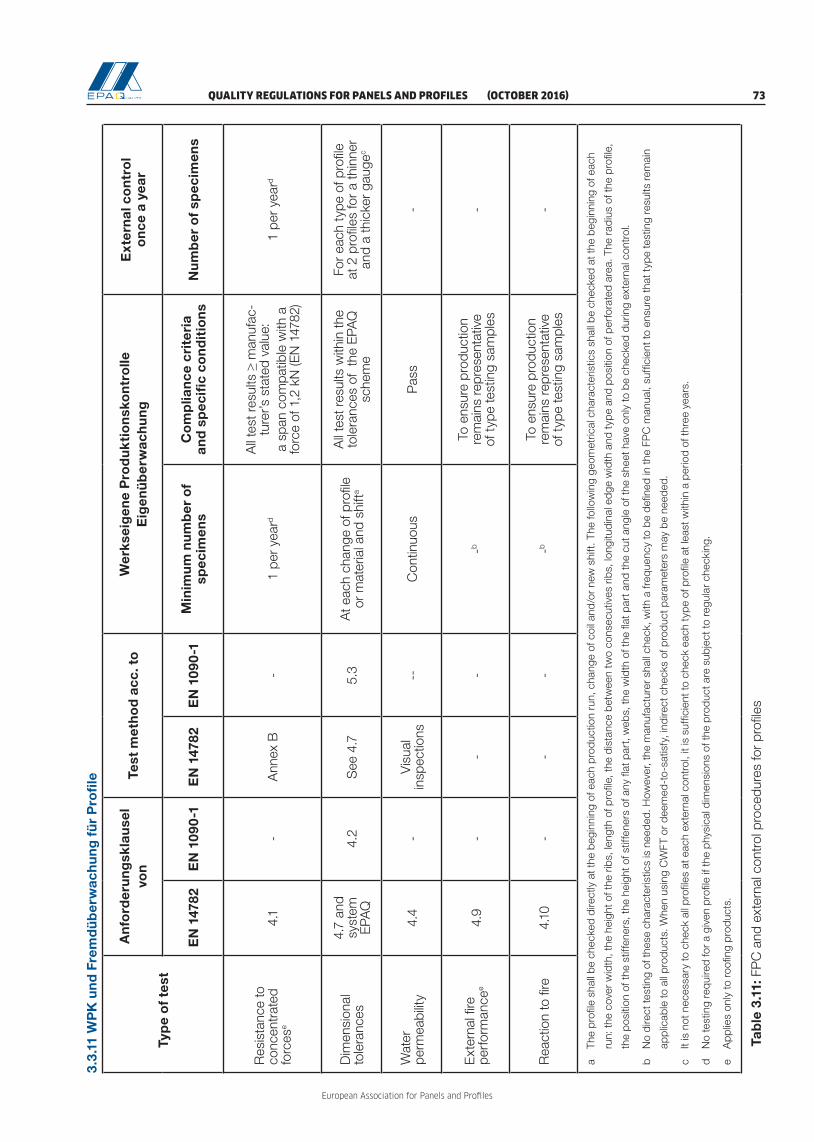
QUALITY REGULATIONS FOR PANELS AND PROFILES (OCTOBER 2016) 73
European Association for Panels and Profiles
a
The
profi
le s
hall
be c
heck
ed d
irect
ly a
t the
beg
inni
ng o
f eac
h pr
oduc
tion
run,
cha
nge
of c
oil a
nd/o
r ne
w s
hift.
The
follo
win
g ge
omet
rical
cha
ract
eris
tics
shal
l be
chec
ked
at th
e be
ginn
ing
of e
ach
ru
n: th
e co
ver
wid
th, t
he h
eigh
t of t
he r
ibs,
leng
th o
f pro
file,
the
dist
ance
bet
wee
n tw
o co
nsec
utiv
es r
ibs,
long
itudi
nal e
dge
wid
th a
nd t
ype
and
posi
tion
of p
erfo
rate
d ar
ea. T
he r
adiu
s of
the
profi
le,
th
e po
sitio
n of
the
stiff
ener
s, th
e he
ight
of s
tiffe
ners
of a
ny fl
at p
art,
web
s, th
e w
idth
of t
he fl
at p
art a
nd th
e cu
t ang
le o
f the
she
et h
ave
only
to b
e ch
ecke
d du
ring
exte
rnal
con
trol
.
b
No
dire
ct te
stin
g of
thes
e ch
arac
teris
tics
is n
eede
d. H
owev
er, t
he m
anuf
actu
rer
shal
l che
ck, w
ith a
freq
uenc
y to
be
defin
ed in
the
FPC
man
ual,
suffi
cien
t to
ensu
re th
at t
ype
test
ing
resu
lts r
emai
n
ap
plic
able
to a
ll pr
oduc
ts. W
hen
usin
g C
WFT
or
deem
ed-t
o-sa
tisfy
, ind
irect
che
cks
of p
rodu
ct p
aram
eter
s m
ay b
e ne
eded
.
c
It is
not
nec
essa
ry to
che
ck a
ll pr
ofile
s at
eac
h ex
tern
al c
ontr
ol, i
t is
suffi
cien
t to
chec
k ea
ch t
ype
of p
rofil
e at
leas
t with
in a
per
iod
of th
ree
year
s.
d
No
test
ing
requ
ired
for
a gi
ven
profi
le if
the
phys
ical
dim
ensi
ons
of th
e pr
oduc
t are
sub
ject
to r
egul
ar c
heck
ing.
e
App
lies
only
to r
oofin
g pr
oduc
ts.
T
able
3.1
1: F
PC
and
ext
erna
l con
trol
pro
cedu
res
for
profi
les
1.1.
1
3.3.
11 W
PK
un
d F
rem
dü
ber
wac
hu
ng
fü
r P
rofi
le
Typ
e o
f te
st
An
ford
eru
ng
skla
use
l vo
nTe
st m
eth
od
acc
. to
W
erks
eig
ene
Pro
du
kti
on
sko
ntr
olle
E
igen
üb
erw
ach
un
gE
xter
nal
co
ntr
ol
on
ce a
yea
r
EN
147
82E
N 1
090-
1E
N 1
4782
EN
109
0-1
Min
imu
m n
um
ber
of
spec
imen
sC
om
plia
nce
cri
teri
a an
d s
pec
ific
con
dit
ion
sN
um
ber
of
spec
imen
s
Res
ista
nce
to
conc
entr
ated
fo
rces
e4.
1-
Ann
ex B
-1
per
year
d
All
test
resu
lts ≥
man
ufac
-tu
rer’s
sta
ted
valu
e:
a sp
an c
ompa
tible
with
a
forc
e of
1,2
kN
(EN
147
82)
1 pe
r ye
ard
Dim
ensi
onal
to
lera
nces
4.7
and
syst
em
EPA
Q4.
2S
ee 4
.75.
3A
t eac
h ch
ange
of p
rofil
e or
mat
eria
l and
shi
fta
All
test
resu
lts w
ithin
the
tole
ranc
es o
f th
e EP
AQ
sc
hem
e
For
each
typ
e of
pro
file
at 2
pro
files
for
a th
inne
r an
d a
thic
ker
gaug
ec
Wat
er
perm
eabi
lity
4.4
-V
isua
l in
spec
tions
--C
ontin
uous
Pas
s-
Ext
erna
l fire
pe
rfor
man
cee
4.9
--
--b
To e
nsur
e pr
oduc
tion
rem
ains
repr
esen
tativ
e of
typ
e te
stin
g sa
mpl
es-
Rea
ctio
n to
fire
4.
10-
--
-bTo
ens
ure
prod
uctio
n re
mai
ns re
pres
enta
tive
of t
ype
test
ing
sam
ples
-

European Association for Panels and Profiles
74 (OCTOBER 2016) QUALITY REGULATIONS FOR PANELS AND PROFILES

QUALITY REGULATIONS FOR PANELS AND PROFILES (OCTOBER 2016) 75
European Association for Panels and Profiles
1.1 3.4. Dimensions of profiles
3.4.1. Dimensions of trapezoidal profiles
+he
–he
–he
Figure 3.1: Cross section - trapezoidal sheet
Figure 3.2: Measuring points for sheet thickness t and deviation of side lap D
Cover width w
+he
-he
-he

European Association for Panels and Profiles
76 (OCTOBER 2016) QUALITY REGULATIONS FOR PANELS AND PROFILES
Figure 3.3: Deviation of side lap D (visible side lap)
~ 10 mm
h
~ 10 mm
Figure 3.4: Measurement of the depth of profile h
Figure 3.5: Measuring points for depth of profile h
D
D
D
Da. b.
5 Ribs
4 Ribs
3 Ribs
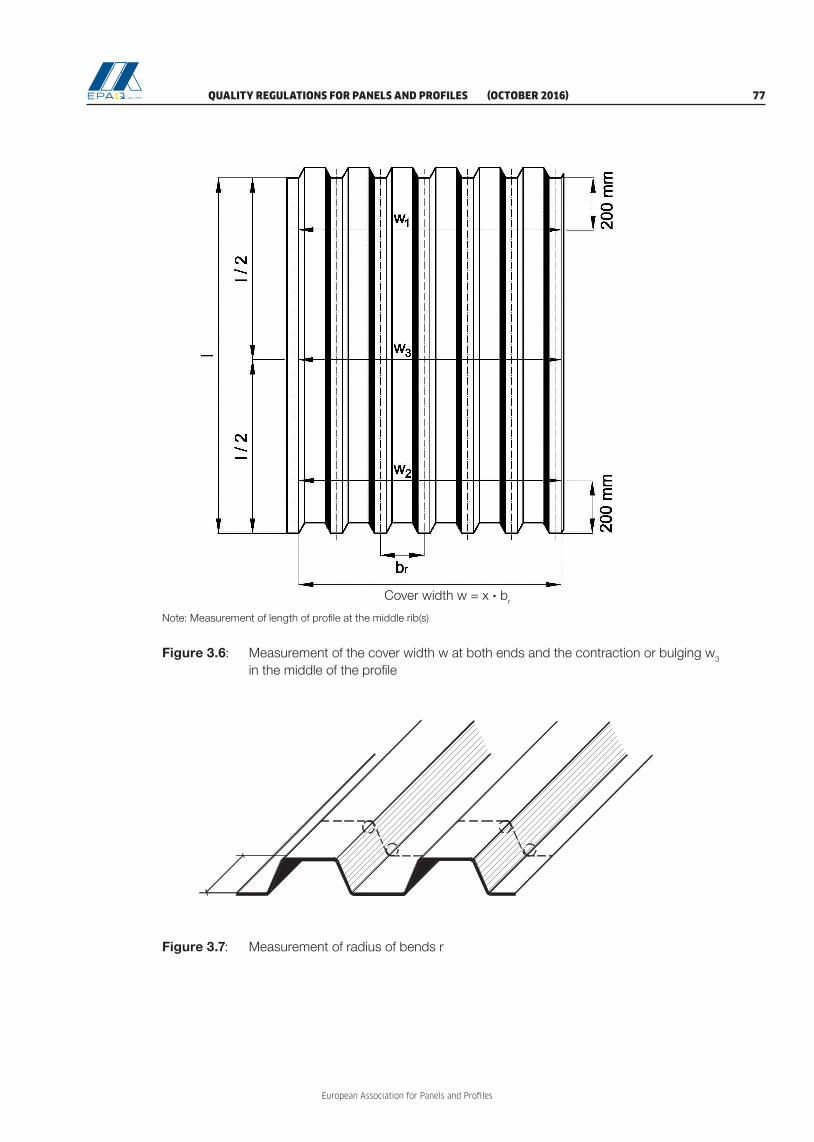
QUALITY REGULATIONS FOR PANELS AND PROFILES (OCTOBER 2016) 77
European Association for Panels and Profiles
Figure 3.6: Measurement of the cover width w at both ends and the contraction or bulging w3 in the middle of the profile
Note: Measurement of length of profile at the middle rib(s)
Figure 3.7: Measurement of radius of bends r
Cover width w = x · br

European Association for Panels and Profiles
78 (OCTOBER 2016) QUALITY REGULATIONS FOR PANELS AND PROFILES
Figure 3.8: Measurement of deviation from straightness δ
1 Central axis
2 Straight line at the edge of crown
δ Deviation of crown from the ideal straight line
Figure 3.9: Measurement of deviation from squareness S
200
mm
200
mm

QUALITY REGULATIONS FOR PANELS AND PROFILES (OCTOBER 2016) 79
European Association for Panels and Profiles
Figure 3.11: Acoustic profiles
dn = Hole diameter
Ux = Vertical hole pitch
Uy = Horizontal hole pitch
Holes
Figure 3.10: Pitch of the profile
Cross section trapezoidal sheet

European Association for Panels and Profiles
80 (OCTOBER 2016) QUALITY REGULATIONS FOR PANELS AND PROFILES
Figure 3.12: Flatness of unstiffened and stiffened flange or web

QUALITY REGULATIONS FOR PANELS AND PROFILES (OCTOBER 2016) 81
European Association for Panels and Profiles
3.4.2. Dimensions of sinusoidal profiles and tiles
p
Figure 3.13: Measuring points for sheet thickness t
Figure 3.14: Measurement of the depth of profile h
Figure 3.15: Measurement of the pitch of the profile p
Figure 3.16: Measurement of cover width w at both ends and of the contraction or bulging w3 in the middle of the profile
Cover width w
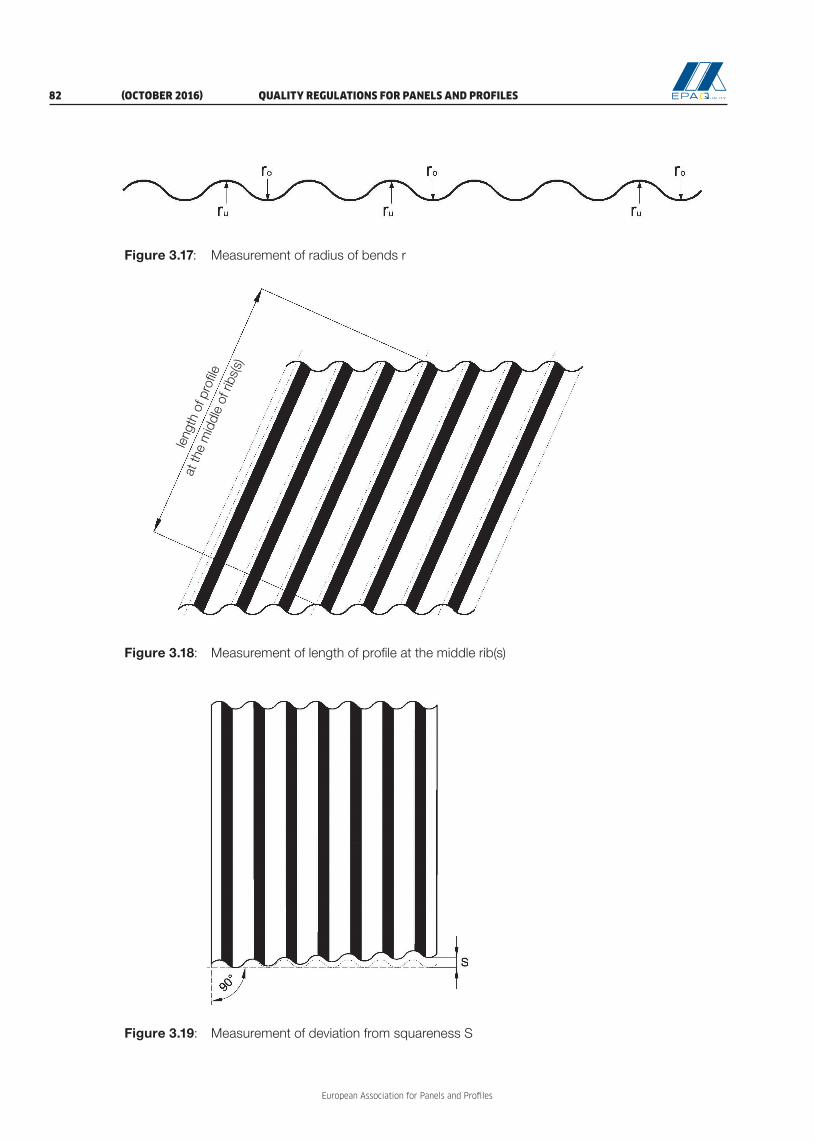
European Association for Panels and Profiles
82 (OCTOBER 2016) QUALITY REGULATIONS FOR PANELS AND PROFILES
Figure 3.17: Measurement of radius of bends r
Figure 3.18: Measurement of length of profile at the middle rib(s)
Figure 3.19: Measurement of deviation from squareness S
leng
th o
f pro
file
at th
e m
iddl
e of
ribs
(s)

QUALITY REGULATIONS FOR PANELS AND PROFILES (OCTOBER 2016) 83
European Association for Panels and Profiles
Figure 3.21: Web angular displacement α (only for tile profiles)
α
-2°+2°
Figure 3.20: Deviation of side lap D
DD

European Association for Panels and Profiles
84 (OCTOBER 2016) QUALITY REGULATIONS FOR PANELS AND PROFILES
3.4.3. Dimensions of liner trays
Figure 3.22: Cross section of liner trays
Figure 3.23: Measuring points for sheet thickness t and depth of profile h
Cover width w

QUALITY REGULATIONS FOR PANELS AND PROFILES (OCTOBER 2016) 85
European Association for Panels and Profiles
Span length L and profile length l for depth of profile:
h ≤ 55 mm: L = 3,00 m l = 4,00 m
h > 55 mm: L = 5,00 m l = 6,00 m
Figure 3.24: Measurement of cover width w, length of profile l and deflection of flange fs
Deflection of flange fs
Figure 3.25: Deviation of side lap D
DD
D
D
a) b)
Cover width w

European Association for Panels and Profiles
86 (OCTOBER 2016) QUALITY REGULATIONS FOR PANELS AND PROFILES
Figure 3.27: Measurement of the lateral curvature and of the longitudinal corrugation
Figure 3.26: Measurement of corner angle flange/web
Corner measure
Measurement of lateral curvature Measurement of longitudinal corrugation
Section A-ASection M-M
M
500mm
ϕ2
ϕ1⊕ Points de fixation
L = Travée
A
A
500mm
500mm
L=5m
O Fixing points
L = Span
500 mm
500 mm
L = 5 m A
A
500 mm
+fq = (fq1 + fq2)/2b
+fq
+fq1
+fq2
b 400 500 600 (mm) fw ± 2 ± 3 ± 5 (mm)
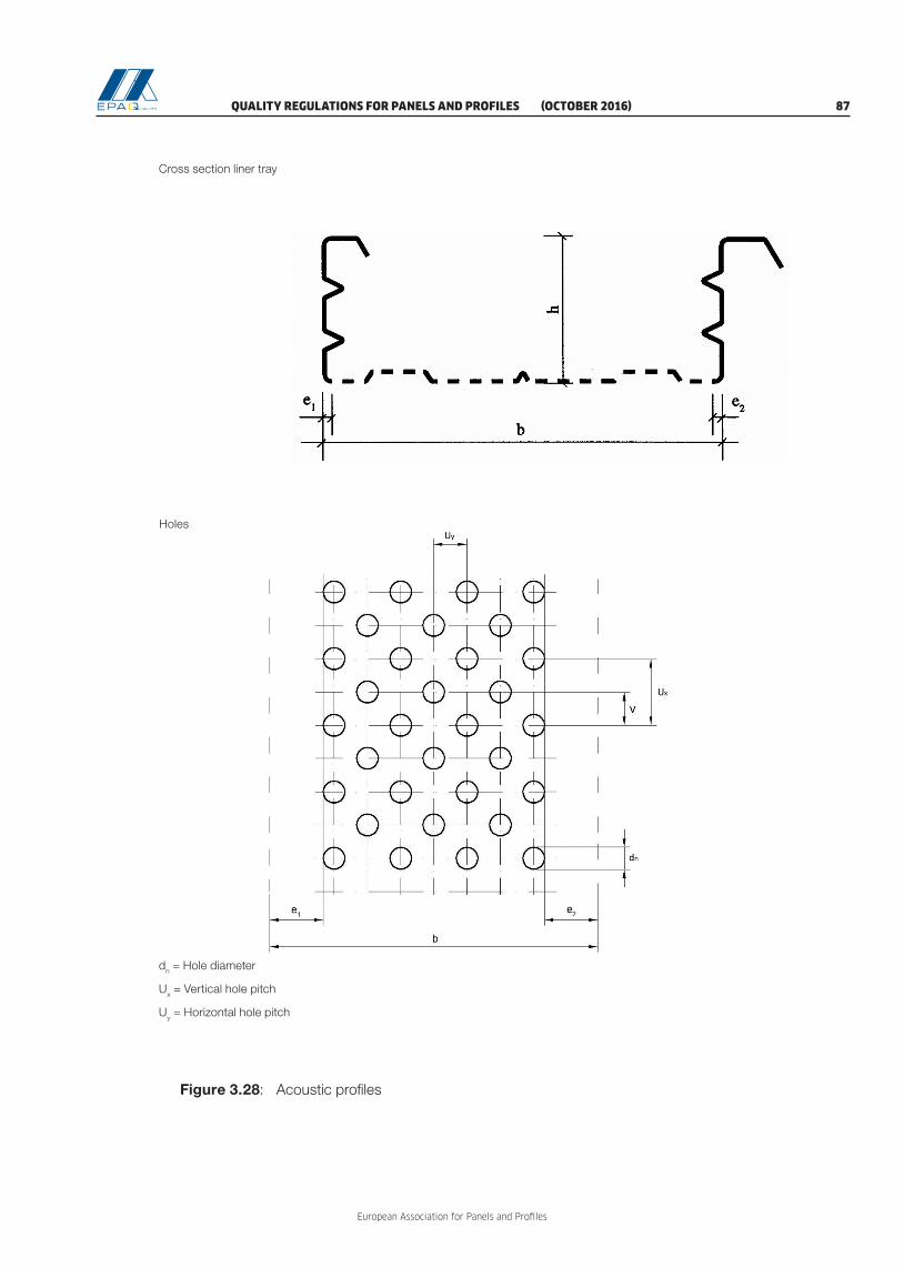
QUALITY REGULATIONS FOR PANELS AND PROFILES (OCTOBER 2016) 87
European Association for Panels and Profiles
Cross section liner tray
Holes
dn = Hole diameter
Ux = Vertical hole pitch
Uy = Horizontal hole pitch
Figure 3.28: Acoustic profiles

European Association for Panels and Profiles
88 (OCTOBER 2016) QUALITY REGULATIONS FOR PANELS AND PROFILES
3.4.4. Dimensions of sidings / façade profiles
Figure 3.29: Cross section of sidings / façade profiles without shadow gap
Figure 3.30: Cross section of sidings / façade profiles with shadow gap
Figure 3.31: Measurement of deviation from straightness δ

QUALITY REGULATIONS FOR PANELS AND PROFILES (OCTOBER 2016) 89
European Association for Panels and Profiles
Figure 3.32: Measurement of deviation from squareness
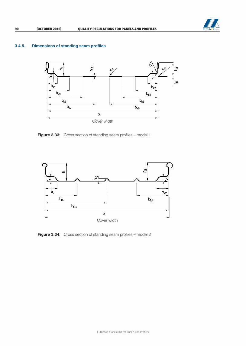
European Association for Panels and Profiles
90 (OCTOBER 2016) QUALITY REGULATIONS FOR PANELS AND PROFILES
3.4.5. Dimensions of standing seam profiles
Figure 3.33: Cross section of standing seam profiles – model 1
Figure 3.34: Cross section of standing seam profiles – model 2
Cover width
Cover width

QUALITY REGULATIONS FOR PANELS AND PROFILES (OCTOBER 2016) 91
European Association for Panels and Profiles
Figure 3.35: Cross section of standing seam profiles – model 3
Figure 3.36: Cross section of standing seam profiles – model 4
Cover width
Cover width

European Association for Panels and Profiles
92 (OCTOBER 2016) QUALITY REGULATIONS FOR PANELS AND PROFILES