
EP2679832A1
28
Printed by Jouve, 75001 PARIS (FR) (19) EP 2 679 832 A1 TEPZZ 6798¥ A_T (11) EP 2 679 832 A1 (12) EUROPEAN PATENT APPLICATION (43) Date of publication: 01.01.2014 Bulletin 2014/01 (21) Application number: 12174154.0 (22) Date of filing: 28.06.2012 (51) Int Cl.: F15B 3/00 (2006.01) F15B 21/14 (2006.01) (84) Designated Contracting States: AL AT BE BG CH CY CZ DE DK EE ES FI FR GB GR HR HU IE IS IT LI LT LU LV MC MK MT NL NO PL PT RO RS SE SI SK SM TR Designated Extension States: BA ME (71) Applicant: Quirós Morales, Luis Fernando Medellin (CO) (72) Inventor: Quirós Morales, Luis Fernando Medellin (CO) (74) Representative: Richter Werdermann Gerbaulet Hofmann Patentanwälte Neuer Wall 10 20354 Hamburg (DE) (54) Hydrostatic energy generator (57) A device and a method for exploiting hydrostatic energy, wherein the device comprises at least a first chamber and a second chamber, wherein the first cham- ber and the second chamber are at least partially filled with a fluid is suggested in order to provide a device and a method for exploiting hydrostatic energy, such as for instance static or hydrostatic pressure or head, to gen- erate and deliver energy, such as for instance hydraulic energy, electrical energy, or mechanical energy, wherein a first piston (13) movably arranged within the first cham- ber (10) and a second piston (14) movably arranged with- in the second chamber (11), wherein the first piston (13) is mechanically or hydraulically connected to the second piston (14), wherein the first chamber (10) comprises at least a first means (15) for inlet and/or discharge of the fluid (12) and a second means (16) for inlet and/or dis- charge of the fluid (12), wherein the second chamber (11) comprises at least a third means (17) for inlet and/or dis- charge of the fluid (12) and a fourth means (18) for inlet and/or discharge of the fluid (12).
-
Upload
victor-von-doom -
Category
Documents
-
view
212 -
download
0
description
PATENT
Transcript of EP2679832A1

Printed by Jouve, 75001 PARIS (FR)
(19)E
P2
679
832
A1
TEPZZ 6798¥ A_T(11) EP 2 679 832 A1
(12) EUROPEAN PATENT APPLICATION
(43) Date of publication: 01.01.2014 Bulletin 2014/01
(21) Application number: 12174154.0
(22) Date of filing: 28.06.2012
(51) Int Cl.:F15B 3/00 (2006.01) F15B 21/14 (2006.01)
(84) Designated Contracting States: AL AT BE BG CH CY CZ DE DK EE ES FI FR GB GR HR HU IE IS IT LI LT LU LV MC MK MT NL NO PL PT RO RS SE SI SK SM TRDesignated Extension States: BA ME
(71) Applicant: Quirós Morales, Luis FernandoMedellin (CO)
(72) Inventor: Quirós Morales, Luis FernandoMedellin (CO)
(74) Representative: Richter Werdermann Gerbaulet HofmannPatentanwälte Neuer Wall 1020354 Hamburg (DE)
(54) Hydrostatic energy generator
(57) A device and a method for exploiting hydrostaticenergy, wherein the device comprises at least a firstchamber and a second chamber, wherein the first cham-ber and the second chamber are at least partially filledwith a fluid is suggested in order to provide a device anda method for exploiting hydrostatic energy, such as forinstance static or hydrostatic pressure or head, to gen-erate and deliver energy, such as for instance hydraulicenergy, electrical energy, or mechanical energy, whereina first piston (13) movably arranged within the first cham-
ber (10) and a second piston (14) movably arranged with-in the second chamber (11), wherein the first piston (13)is mechanically or hydraulically connected to the secondpiston (14), wherein the first chamber (10) comprises atleast a first means (15) for inlet and/or discharge of thefluid (12) and a second means (16) for inlet and/or dis-charge of the fluid (12), wherein the second chamber (11)comprises at least a third means (17) for inlet and/or dis-charge of the fluid (12) and a fourth means (18) for inletand/or discharge of the fluid (12).
EP 2 679 832 A1
2
5
10
15
20
25
30
35
40
45
50
55
Description
Background
[0001] Various Systems exist to generate energy, suchas for instance electrical energy, which are using energysources such as for instance wind power, solar energy,or water current as a primary source. However, there isno commercial system available, which can generate en-ergy based on hydrostatic energy source, such as a hy-drostatic pressure or head.
Description of the invention
Object
[0002] The aim of the present invention is to provide adevice and a method for exploiting hydrostatic energy,such as for instance static or hydrostatic pressure orhead, to generate and deliver energy, such as for in-stance hydraulic energy, electrical energy, or mechanicalenergy. It is further the aim of the invention, to provide adevice with a relatively simple and economic structure tobe used in a commercial energy generation system.Wherein in the following pressure or hydrostatic potentialis meant by head. Static pressure or hydrostatic pressureor head is the pressure exerted by a fluid on a body whenthe body is at rest relative to the fluid.
Solution
[0003] According to the invention, a device for exploit-ing hydrostatic energy is suggested, wherein the devicecomprises at least a first chamber and a second chamber,wherein the first chamber and the second chamber areat least partially filled with a fluid. Furthermore, the in-ventive device comprises a first piston moveably ar-ranged within the first chamber and a second pistonmoveably arranged within the second chamber, whereinthe first piston is mechanically or hydraulically connectedto the second piston, wherein the first chamber compris-es at least a first means for inlet and/or discharge of thefluid and a second means for inlet and/or discharge ofthe fluid, wherein the second chamber comprises at leasta third means for inlet and/or discharge of the fluid anda fourth means for inlet and/or discharge of the fluid.[0004] By a means for inlet, it is to be understood thatthe fluid can enter the according chamber through thismeans. By means for discharge it is to be understoodthat the fluid can exit the according chamber through thismeans. Therefore, discharge stands for outlet.[0005] The first chamber and the second chamber canin principle be designed in any shape. For instance thetwo chambers can have an angular, or a cylindricalshape. For example, the first chamber and/or the secondchamber comprise a circular, elliptical, rectangular,quadratic or other cross section. Furthermore, the twochambers can have equal or a different shape. Each pis-
ton arranged in the according chamber comprises thesame principal shape as the according chamber. It ispreferred, that the two chambers have a different size.For example, the second chamber can have a larger sizethan the first chamber and therefore comprises a largervolume than the first chamber.[0006] The first piston is connected to the second pis-ton by any appropriate mechanical or hydraulic connec-tion means. The two means for inlet and/or discharge ofthe fluid at each of the two chambers can be any appro-priate means for inlet and/or discharge of a fluid. For in-stance these means for inlet and/or discharge of the fluidcan consist of pipes, holes drilled through the chamberwall or others. The fluid within each of the chambers canbe any kind of fluid. For instance the fluid can be a liquid,such as water, oil, petroleum, or any other kind of appro-priate liquid. Furthermore, the fluid can be gaseous. Forinstance, the fluid within each of the two chambers canbe air, oxygen or any other kind of appropriate gas. Fur-thermore, the fluid can be compressible or incompress-ible, Newtonian or non-Newtonian, pure substances ormixtures. Even if not necessary, it is preferred, that eachchamber is at least partially filled with the identical fluid.[0007] The inventive device can be arranged in anyappropriate way. For instance, the inventive device canbe arranged in such a way that the two chambers arearranged one above the other. Furthermore, it is possibleto arrange the two chambers next to one another. Fur-thermore, it is possible to connect both chambers witheach other. Furthermore it is possible to arrange bothchambers in a distance to each other, wherein the dis-tance between the two chambers comprises a free spaceor a space filled with any appropriate material.[0008] Preferably, at least one means for inlet and/ordischarge of the fluid is connected to a supply source,e.g. a static pressure, a hydrostatic pressure or headsource. For example the one means for inlet and / ordischarge of the fluid is supplied with a pressure existingon a certain depth or water level within a tank, lake orany other arrangement filled with a fluid, e.g. water, airor other. Additionally, it is possible to connect this meansfor inlet and/or discharge of the fluid to a pressure tankor pressure vessel, e.g. a pressurized hydro-pneumatictank. Any other kind of fluid can be used as well. Theincoming hydrostatic pressure will then cause the pistonarranged within the according chamber to move upand/or down or back and/or forwards. In order to ensurea continuous reciprocating movement of the piston, themeans for inlet and/or discharge of the fluid can be con-trolled, for instance be opened or closed, in any appro-priate way. The reciprocating movement of the pistonscan be used to generate any kind of energy. For instancethe movement of the pistons can be used to generate ahydraulic energy, in particular an increased pressure orhead. The movement of the pistons can be used to gen-erate mechanical or electrical energy. Energy can alsobe generated from any single or individual stroke of thefirst piston and/or the second piston. However, a recip-
1 2

EP 2 679 832 A1
3
5
10
15
20
25
30
35
40
45
50
55
rocating movement is preferred.[0009] It is preferred, that the first piston splits up theinterior of the first chamber into a first volume and a sec-ond volume and wherein the first means for inlet and/ordischarge of the fluid is allocated to the first volume andwherein the second means for inlet and/or discharge ofthe fluid is allocated to the second volume and whereinthe second piston splits up the interior of the secondchamber into a third volume and a fourth volume andwherein the third means for inlet and/or discharge of thefluid is allocated to the third volume and wherein thefourth means for inlet and/or discharge of the fluid is al-located to the fourth volume. Preferably, each volume orspace is fully or completely filled with the fluid. The sizeof each volume or space, within each chamber variesduring operation of the inventive device due to the recip-rocating movement of the first and second piston. It ispreferred that the stroke or distance of each movementis identical for the first and the second piston.[0010] The first piston can be connected to the secondpiston by any appropriate connection means. Therefore,the first piston can move in an opposite direction to themovement of the second piston. However, it is preferredthat the first piston is connected to the second piston insuch a way, that both pistons move synchronously toeach other and in the same direction with each stroke. Itis further preferred, that the first volume or space withinthe first chamber and the third volume or space withinthe second chamber are decreased or increased at thesame point of time due to the movement of the first pistonand the second piston.[0011] Each means for inlet and/or discharge of thefluid is arranged at an end region of the volume thismeans is allocated to. For example, the first means forinlet and/or discharge of the fluid is arranged at a firstfront side of the first chamber or at a side wall of the firstchamber close to the first front side of the first chamberor at the corner region between the first front side of thefirst chamber and a side wall of the first chamber. There-fore, each means for inlet and/or discharge of the fluid isarranged in such a way, that it is not covered by a pistonduring its movement.[0012] It is further preferred that the first chamber com-prises a fifth means for inlet and/or discharge of the fluidand a sixth means for inlet and/or discharge of the fluidand wherein the second chamber comprises a seventhmeans for inlet and/or discharge of the fluid and a eighthmeans for inlet and/or discharge of the fluid. Preferablyalways two means for inlet and/or discharge of the fluidare allocated to an identical volume. For example, thefirst and the fifth means of inlet and/or discharge of thefluid are both allocated to the first volume, and the secondand sixth means for inlet and/or discharge of the fluid areboth allocated to second volume, and the third and sev-enth means for inlet and/or discharge of the fluid are bothallocated to third volume, and the fourth and eighthmeans for inlet and/or discharge of the fluid are both al-located to the fourth volume.
[0013] Additionally, the device preferably comprises afirst tank, wherein the first tank is connected by a con-nection means to the first means for inlet and/or dis-charge of the fluid and/or that the first tank is connectedby a connection means to the second means for inletand/or discharge of the fluid and/or that the first tank isconnected by a connection means to the third means forinlet and/or discharge of the fluid and/or that the first tankis connected by a connection means to the fourth meansfor inlet and/or discharge of the fluid and/or that the firsttank is connected by a connection means to the fifthmeans for inlet and/or discharge of the fluid and/or thatthe first tank is connected by a connection means to thesixth means for inlet and/or discharge of the fluid and/orthat the first tank is connected by a connection means tothe seventh means for inlet and/or discharge of the fluidand/or that the first tank is connected by a connectionmeans to the eighth means for inlet and/or discharge ofthe fluid. The first tank can be used as an auxiliary tankfor temporary collecting or storing the fluid. Appropriateconnection means for connecting the first tank with anyof the means for inlet and/or discharge of the fluid canbe any connection means appropriate for moving the flu-id. For example, pipes can be used as connection meanswhich allow the fluid, e.g. water, to move or flow fromand/or to the first tank.[0014] The first tank can be arranged next to the firstchamber and/or next to the second chamber. Further-more, the first tank can be arranged above the first cham-ber and/or above the second chamber. The first tank canbe any appropriate repository, bin or container. Further-more, the first tank can consist of any possible shape.Additionally, the first tank can be opened or closed. Pref-erably, the pressure within an opened or closed first tankis in the range of the atmospheric pressure, for examplewithin the range of the atmospheric air pressure. The firsttank can be located close to the inventive device or at acertain distance to the inventive device. It is further pos-sible to locate the first tank far away, for example multiplemeters or kilometers, away from the inventive device.[0015] It is further preferred that the first tank is at leastpartially arranged around the first chamber and/or aroundthe second chamber. The first tank can comprise sepa-rate walls. It is further possible that the outer wall of thefirst chamber or the second chamber is used as a wallfor the first tank.[0016] Preferably, at least one means for inlet and/ordischarge of the fluid is connected to a supply source,e.g. a static pressure, a hydrostatic pressure or headsource. For this reason, this means for inlet and/or dis-charge of the fluid is supplied with a higher pressure com-pared with the pressure in the first tank of the device, e.g.pressure in the first tank could be the atmospheric pres-sure, or pressure in the first tank could be higher or lowerthan the atmospheric pressure. For example the onemeans for inlet and/or discharge of the fluid is suppliedwith a pressure existing on a certain depth or water levelwithin a tank, lake or any other arrangement filled with a
3 4

EP 2 679 832 A1
4
5
10
15
20
25
30
35
40
45
50
55
fluid, e.g. water, or it can be supplied with atmosphericpressure, e.g. the atmospheric air pressure, if the firsttank comprises enough vacuum pressure.[0017] Additionally the device comprises a manual orautomatic control system in particular, valves or an au-tomatic hydraulic directional valve. A valve can be ar-ranged at or within the means for inlet and/or dischargeof the fluid. Furthermore, the valves can be arranged with-in or at the connection means. The control system, e.g.the valves, is used to control the flow of the fluid and inparticular the direction of the flow of the fluid througheach of the means for inlet and/or discharge of the fluid.Furthermore the control system, e.g. valves, is used tostop and/or initiate the flow or movement of the fluidthrough a means for inlet and/or discharge of the fluid.The control system can for example set a certain config-uration for all means for inlet and/or the discharge of thefluid at any certain point of time. For example, at a pointof time the first means for inlet and/or discharge of thefluid can be configured or activated for inlet, wherein thesecond means for inlet and/or discharge of the fluid isconfigured or activated for discharge or outlet, andwherein the third means for inlet and/or discharge of thefluid is configured or activated for inlet, and wherein thefourth means for inlet and/or discharge of the fluid is con-figured or activated for discharge or outlet. Valves usedfor the control system can consist of any appropriate typeof valves. For example such valves can be check valves,or any type of shut off valves, e.g. gate, ball, butterfly,globe or membrane valves, or combination of some ofthese valves.[0018] That at least two means for inlet and/or dis-charge of the fluid are connected by connection meanswherein the connection means or preferably comprisingpipes and/or holes internally drilled inside and along thechamber walls. The pipes can consist of flexible or non-flexible pipes. Furthermore, the pipes can consist of acombination of flexible and non-flexible pipes. Holeswhich are internally drilled inside and along the chamberwalls can be arranged along the entire length of a wallof the first chamber and/or the second chamber. Further-more it is possible, that the holes internally drilled insideand along the chamber walls are arranged along a partof the length of the first chamber and/or the second cham-ber. It is also possible, that the chamber walls are con-sisting of a double-walled arrangement, wherein thespace between the two walls of the double-walled ar-rangement is used as the connection means.[0019] Preferably, at least one of the means for inletand/or discharge of the fluid allocated to the first volumeis connected to at least one of the means for inlet and/ordischarge of the fluid allocated to the fourth volume. Fur-thermore it is preferred that at least one of the means forinlet and/or discharge of the fluid allocated to the thirdvolume is connected to at least one of the means for inletand/or discharge of the fluid allocated to the second vol-ume. The word "connected" means that the fluid can flowor move through the connection means. The flow of the
fluid can be controlled and/or stopped or interrupted bythe control system, e.g. valves within or at the pipes.[0020] It is further preferred, that the first piston com-prises a first front side with a first surface area and where-in the first piston comprises a second front side with asecond surface area and wherein the first surface areais larger than the second surface area and wherein thesecond piston comprises a third front side with a thirdsurface area and a fourth front side with a fourth surfacearea, and wherein the fourth surface area is larger thanthe third surface area. It is further preferred that the fourthsurface area of the second piston is larger than the firstsurface area of the first piston. It is further preferred thatthe third surface area of the second piston is larger thanthe second surface area of the first piston.[0021] Therefore it is preferred, that each front side ofthe first piston comprises a larger and a smaller surfacearea. Furthermore, it is preferred that each front side ofthe second piston comprises a larger and a smaller sur-face area. Therefore, each piston comprises two frontsides with different surface areas in size. It is further pre-ferred, that the connection means used to mechanicallyor hydraulically connect the first piston with the secondpiston is connected to a front side of the first piston andto a front side of the second piston. For instance, theconnection means can be a bar, or a rod. Due to theconnection area or interface area needed for connectingsuch a connection means, e.g. rod, at one of the frontsides of a piston, the remaining and effective surfacearea of this front side is reduced. The surface area of afront side of a piston is the contact area between the fluidand the according front side of the piston. Therefore, thehydrostatic pressure, e.g. the energy source for the in-ventive device, can be applied to different surface areasof a piston.[0022] Since both pistons are connected to each other,the same force is applied to each piston during movementof the two pistons. However, since the surface areas ofeach front side of a piston are different, a higher pressureis obtained in the side of the chamber with a smaller sur-face area of the front side of the piston. Therefore, thepressure in the first volume of the first chamber can bedifferent to the pressure in the second volume of the firstchamber during movement of the first piston. Further-more, the pressure within the third volume of the secondchamber is different to the pressure in the fourth volumeof the second chamber during movement of the secondpiston. Furthermore, since the fourth surface area of thesecond piston is larger than the first surface area of thefirst piston, the pressure in the first volume of the firstchamber can be different from the pressure in the fourthvolume of the second chamber during movement of thefirst and the second piston. Furthermore, since the thirdsurface area of the second piston is larger than the sec-ond surface area of the first piston, the pressure in thesecond volume of the first chamber can be different fromthe pressure in the third volume of the second chamberduring movement of the first and the second pistons. The
5 6

EP 2 679 832 A1
5
5
10
15
20
25
30
35
40
45
50
55
advantage of heaving different surface or contact areasat each front side of the pistons is that high forces andhigh discharge pressures can be advantageously gen-erated at the same time.[0023] It is preferred, that a means for sealing, e.g. aset of 0-rings, is arranged between the first piston andthe wall of the first chamber and between the secondpiston and the wall of the second chamber.[0024] It is further preferred, that a means for sealing ,e.g. a set of O-rings, is arranged between the connectionmeans, e.g. rod, for connecting the first piston with thesecond piston, and a chamber wall of the first chamberand between this connection means and a chamber wallof the second chamber.[0025] It is further possible, that the increased dis-charge pressure is discharged or provided into a pres-sure tank, e.g. a pressurized hydro-pneumatic tank.[0026] Furthermore, a pressure tank, e.g. a pressu-rized hydro-pneumatic tank, can be used as the sourceof incoming hydrostatic pressure. This hydrostatic pres-sure has in this case been previously charged in the hy-dro-pneumatic tank by using for example pressurized air.Since discharge pressure is significantly higher than thehydrostatic pressure in the hydro-pneumatic tank, thedischarged flow can be easily injected back into the hy-dro-pneumatic tank. This means, that only a very smallpart of the total discharged energy is taken to inject thisflow back. The remaining energy (which is the higherpart) is then available to be utilized to carry out any spe-cific work.[0027] Mentioned pressure tanks, e.g. hydro-pneu-matic tanks, could include, or could not, a flexible mem-brane to internally separate pressurized air from internalliquid (for example water), to avoid air leakage throughthe liquid itself, and thus optimizing the system.[0028] Two or more devices can be connected in se-ries. Series connections can be used to increase the dis-charge pressure over the discharge pressure of only onedevice. Furthermore, two or more devices can be con-nected in parallel. Parallel connections can be used toincrease the discharge flow over the discharge flow ofonly one device.[0029] Combination of one or more devices connectedin series with one or more devices connected in parallelcan be used to achieve any determined hydraulic result(increased head and/or increased flow).[0030] According to the invention, an automatic hy-draulic directional valve specially designed as part of theinvention, in particular to be used for a device for exploit-ing hydrostatic energy is further preferred to provide au-tomatic control for the different means for inlet and / ordischarge of the fluid.[0031] It is preferred that the automatic hydraulic di-rectional valve comprises at least a third piston, whereinthe automatic hydraulic directional valve is connected tothe first means for inlet and / or discharge of the fluid andto the second means for inlet and / or discharge of thefluid and to the third means for inlet and / or discharge
of the fluid and to the fourth means for inlet and / or dis-charge of the fluid to control the flow direction of the fluidto and from the first volume, the second volume, the thirdvolume, and the fourth volume.[0032] According to the invention a method for exploit-ing hydrostatic energy with a device in particular accord-ing to claims 1 to 9 is further suggested, wherein thedevice comprises a first chamber and a second chamber,wherein the first chamber and the second chamber areat least partially filled with a fluid, a first piston movablyarranged within the first chamber and a second pistonmovably arranged within the second chamber, whereinthe first piston is mechanically or hydraulically connectedto the second piston by connection means, wherein thefirst chamber comprises at least a first means for inletand / or discharge of the fluid and a second means forinlet and / or discharge of the fluid, wherein the secondchamber comprises at least a third means for inlet and /or discharge of the fluid and a fourth means for inlet and/ or discharge of the fluid, wherein the first piston splitsup the interior of the first chamber into a first volume anda second volume, wherein the first means for inlet and/ordischarge of the fluid is allocated to the first volume andwherein the second means for inlet and/or discharge ofthe fluid is allocated to the second volume and whereinthe second piston splits up the interior of the secondchamber into a third volume and a fourth volume, whereinthe third means for inlet and/or discharge of the fluid isallocated to the third volume and wherein the fourthmeans for inlet and/or discharge of the fluid is allocatedto the fourth volume, wherein the method comprises thefollowing steps:
a) activating the fourth means for inlet and / or dis-charge of the fluid to let the fluid flow into the secondchamber to increase the fourth volume, andb) activating the third means for inlet and / or dis-charge of the fluid to let the fluid at least partially flowout of the second chamber to decrease the third vol-ume, andc) activating the second means for inlet and / or dis-charge of the fluid to let the fluid flow into the firstchamber to increase the second volume, andd) activating the first means for inlet and / or dis-charge of the fluid to let the fluid at least partially flowout of the first chamber to decrease the first volume,
wherein a pressure difference between the first volumeand the second volume of the first chamber and / or be-tween the third volume and the fourth volume of the sec-ond chamber and / or between the fourth volume of thesecond chamber and the first volume of the first chamber,and/or between the third volume of the second chamberand the second volume of the first chamber is generatedto move the first piston and the second piston, whereinhydraulic energy, in particular an increased pressure orhead, mechanical energy or electrical energy is gener-ated.
7 8

EP 2 679 832 A1
6
5
10
15
20
25
30
35
40
45
50
55
[0033] It is preferred that, after performing steps a) tod) and after the first piston and the second piston havemoved, the activation of the means for inlet and / or dis-charge of the fluid is reverted or other means are acti-vated to move the first piston and the second piston inthe reverse direction within each chamber. Before revert-ing the means for inlet and/or discharge of the fluid, it ispreferred that all means are closed for a certain, prefer-ably small, period of time. Instead of reverting the meansfor inlet and/or discharge of the fluid, other means pref-erably additional means or a combination of additionalmeans and the first and/or the second and/or the thirdand/or the fourth means for inlet and/or discharge of thefluid can be activated in such a manner to move the firstpiston and the second piston back to their previous po-sitions.[0034] It is further preferred, that the activation of themeans for inlet and /or discharge of the fluid is continu-ously reverted or activated in time intervals, preferablyin regular time intervals, to generate a reciprocatingmovement of the first piston and the second piston. Thetime interval for reverting or activating the means for inletand/or discharge of the fluid is at least that large to guar-antee that the first piston and the second piston havestopped or completed the movement into one direction.It is further preferred, that a control unit or system is usedwhich checks that the movement of both pistons into onedirection is completed and that a predefined time intervalhas elapsed. Therefore, based on the position of bothpistons and the time elapsed within an interval, the meansof inlet and/or discharge of the fluid are reverted or acti-vated to move the two pistons into the reverse directioncompared with their previous movement.[0035] Preferably, one of the means for inlet and / ordischarge which is activated to let the fluid into the firstchamber or into the second chamber is applied to a staticpressure source. The static pressure source is used asan inlet pressure source. Therefore, one of the meanscan be connected to a pressure tank or pressure vessel,e.g. an hydro-pneumatic-tank. Alternatively, one of themeans can be opened for inlet of the fluid, while the de-vice or at least the according chamber is exposed to acertain hydrostatic pressure. For example, the device canbe arranged at a certain depth within a water tank, wetwell, lake, ocean, etc.[0036] It is additionally preferred, that the fluid whichflows at least partially out of the second chamber to de-crease the fourth volume is at least partially flowing intothe first chamber while increase the first volume and / orinto a first tank for temporarily storing the fluid, and / orthat the fluid which flows at least partially out of the sec-ond chamber to decrease the third volume is at leastpartially flowing into a second tank for discharging thefluid or pressure, and / or that the fluid flows at least par-tially into the first chamber to increase the second volumeand / or from a first tank taking the volume previously andtemporarily stored and / or the fluid flows out of the firstchamber to decrease the first volume and flows to the
second tank for discharging the fluid or pressure. It ispreferred, that the second means for inlet and/or dis-charge of the fluid is connected with the third means forinlet and/or discharge fluid so that the fluid can move orflow from one of the two means for inlet and/or dischargeof the fluid to the other and vice versa.[0037] Furthermore, it is preferred, that electrical ormechanical energy is generated by using an increaseddischarge pressure of the fluid letting out of the first cham-ber and / or the second chamber by driving means formechanical operation, or by driving means for electricalenergy generation, in particular a turbine and / or gener-ator. For example, one or multiple means for inlet and/ordischarge of the fluid can be connected to a first or secondtank for discharging the outlet pressure. The fluid exitsthe first chamber or the second chamber at a higher pres-sure level compared with the inlet pressure source. Thehigher discharge pressure can be used to pump or liftthe fluid up to a certain height into a discharge tank. Thedischarge tank can be opened in order for the fluid to exitand to drive a turbine and / or a generator.[0038] Preferably, mechanical energy is generated byconnecting driving means for mechanical operation, inparticular a fly-wheel, to the first piston and / or to thesecond piston and / or to a connection means connectingthe first piston to the second piston. In this case, the in-coming hydrostatic pressure, once in the interior of thedevice, and due to differences in surface areas of eachpiston, moves the interior pistons up and down or back-and-forth (in a reciprocating movement) which is convert-ed into rotational movement. The driving means, e.g. thefly-wheel can be used to store rotational energy and/orto stabilize rotational speed and/or to generate mechan-ical energy. The mechanical energy generated can beused to move any machine in any application. Examplesof such machines or applications are cars, automobiles,trucks, ships, submarines, trains, airplanes, airships, hel-icopters, space shuttles, aerospace vehicles, etc. Inthese cases the hydrostatic energy generator would re-place any engine, turbine or prime mover for these vehi-cles.[0039] It is also preferred, that electrical energy is gen-erated by producing a changing magnetic field based onthe reciprocating movement of the first piston and / orthe second piston. This configuration of the device isbased on the Faraday’s Law of electromagnetic induc-tion, which applies to the production of electric currentacross a conductor moving through a magnetic field. Thislaw states that "the electromotive force (EMF) around anelectric closed path is proportional to the rate of changeof the magnetic flux through any surface bounded by thatpath". In other words "an electric current will be inducedin any closed circuit when the magnetic flux through asurface bounded by the conductor changes". This ap-plies whether the field itself changes in strength or theconductor is moved through it. The incoming hydrostaticpressure, once in the interior of the device, due to differ-ences in surface areas of each piston, moves the interior
9 10
EP 2 679 832 A1
7
5
10
15
20
25
30
35
40
45
50
55
pistons up and down or back-and-forth (in a reciprocatingmovement). This movement is then used to produce thenecessary changing magnetic field to produce electricenergy.[0040] The invention will now be described with refer-ence to the figures based on preferred embodiments ofthe invention.
Brief description of the drawings:
[0041]
Fig. 1a shows the basic arrangement of the devicefor exploiting hydrostatic energy,Fig. 1b shows the different surface areas of the sec-ond piston as an example,Fig. 2a-f show the sequence and explain the proce-dure of the different steps and how the device isworking as a hydrostatic energy generator,Fig. 3a-b show an embodiment of the device for ex-ploiting hydrostatic energy with individual exit pipes,Fig. 4 shows an application wherein the device forexploiting hydrostatic energy can be used for deliv-ering hydraulic energy,Fig. 5 shows a principal application for generatingmechanical energy,Fig. 6 shows an application for generation of electri-cal energy,Fig. 7a shows the principal inventive device for ex-ploiting hydrostatic energy with an incoming sourceand an outlet, such as a higher pressure energy level,Fig. 7b shows the principal inventive device connect-ed to a pressure tank, e.g. a hydro-pneumatic tank,Fig. 7c shows the device for exploiting hydrostaticenergy connected to a hydrostatic pressure sourcesuch as a pressurized hydro-pneumatic tank,Fig. 7d shows two devices for exploiting hydrostaticenergy connected in series,Fig. 7e shows two devices for exploiting hydrostaticenergy connected in parallel to each other,Fig. 8 shows the hydrostatic energy generator inter-nal piston, included in the device for exploiting hy-drostatic energy,Fig. 9a-b show the movement of the position of thevalve internal piston included in the automatic direc-tional valve.
Preferred embodiments of the invention
[0042] Fig. 1a shows the basic arrangement of the de-vice for exploiting hydrostatic energy. The device com-prises a first chamber 10 and a second chamber 11. Afirst piston 13 is moveably arranged within the first cham-ber 10 and a second piston 14 is moveably arrangedwithin the second chamber 11. The first piston 13 ismechanically connected to the second piston 14 by astamp, rod 38, or pipe or any other appropriate connec-tion means. The first piston 13 splits the entire volume
within the first chamber 10 into a first volume 19 and asecond volume 20. A first means 15 for inlet and/or dis-charge of the fluid 12 is allocated to the first volume 19of the first chamber 10. A second means 16 for inletand/or discharge of the fluid 12 is allocated to the secondvolume 20 of the first chamber 10. Furthermore the sec-ond piston 14 splits up the entire volume within the sec-ond chamber 11 into a third volume 27 and fourth volume28. A third means 17 for inlet and/or discharge of the fluid12 is allocated to the third volume 27 of the second cham-ber 11 and a fourth means 18 for inlet and/or dischargeof the fluid 12 is allocated to the fourth volume 28 of thesecond chamber 11. In this basic arrangement of a deviceof exploiting hydrostatic energy, the four means 15, 16,17, 18 for inlet and/or discharge of the fluid 12 consist ofholes drilled through the chamber walls. Pipes can beconnected to each of the four means 15, 16, 17, 18 forinlet and/or discharge of the fluid 12. As shown in Fig.1a, the device 100 for exploring hydrostatic energy canfurther comprise additional means 21, 22, 23, 24 for inletand/or discharge of the fluid 12. Fig. 1a shows a device100 with always two means 15, 16, 17, 18, 21, 22, 23,24 for inlet and/or discharge of the fluid 12 allocated toeach of the four volumes 19, 20, 27, 28. Each means 15,16, 17, 18, 21, 22, 23, 24 for inlet and/or discharge of thefluid 12 is arranged at a chamber wall 33a, 33b, 33c, 33d,33e, 33f, 33g, 33h in an area close to one of the frontsides 33a, 33c, 33e, 33g of each of the two chambers10, 11. The means 15, 16, 17, 18, 21, 22, 23, 24 for inletand/or discharge of the fluid 12 can also be arranged atthe front sides 33a, 33c, 33e, 33g of each chamber 10,11 instead at the chamber walls close to the front sidesof each chamber 10, 11.[0043] The first piston 13 contains a first front side 34with a larger surface area 34a than the surface area 35aof the second front side 35 of the first piston 13. Thesecond piston 14 contains a first front side 36 with a small-er surface area 36a than the surface area 37a of thesecond front side 37 of the second piston 14. Each piston13, 14 contains two front sides 34, 35, 36, 37 with a dif-ferent surface area 34a, 35a, 36a, 37a because the twopistons 13, 14 are mechanically connected to each otherby a rod 38 which is connected at the center point of onefront side 34, 35, 36, 37 of each piston 13, 14.[0044] Fig. 1b shows the different surface areas 36a,37a of the second piston 14 as an example.[0045] Fig. 2a to 2f show the sequence and explain theprocedure of the different steps and how the device isworking as a hydrostatic energy generator. The Fig. 2ato 2f explain in detail the sequence and the general op-erational procedures of such a hydrostatic generator.[0046] In Fig. 2a to 2f, the basic arrangement of a de-vice 100 for exploiting hydrostatic energy based on Fig.1 is connected to a primary hydrostatic pressure source40 through pipes 32a and 32b. The pipe 32a contains ashut off valve 30b for controlling the third means 17 forinlet and/or discharge of the fluid 12. The pipe 32b con-tains a shut off valve 30a for controlling the fourth means
11 12

EP 2 679 832 A1
8
5
10
15
20
25
30
35
40
45
50
55
18 for inlet and/or discharge of the fluid 12. The first tank25 is connected to the fifth means 21, to the secondmeans 16, and to the eight means 24 for inlet and/ordischarge of the fluid 12 through the pipe 32c. The pipe32c contains a shut off valve 30c for controlling the eightmeans 24 for inlet and/or discharge of the fluid 12. Fur-thermore the pipe 32c contains a shut off valve 30h anda check valve 30g for controlling the second means 16for inlet and/or discharge of the fluid 12. Furthermore thepipe 32c contains a check valve 30i for controlling theflow direction of the fluid 12 to the fifth means 21 for inletand/or discharge of the fluid 12. The first tank 25 com-prises an auxiliary tank for temporally storing the fluid 12.A second tank 39 is connected to the first means 15 forinlet and/or discharge of the fluid 12 through pipes 32fand 32e. Furthermore, the second tank 39 is connectedto the sixth means 22 and to the seventh means 23 forinlet and/or discharge of the fluid 12 through pipes 32fand 32d. Pipe 32d contains a check valve 30f for con-trolling the flow direction of the fluid 12 to and from thesixth means 22 for inlet and/or discharge of the fluid 12.Furthermore, the pipe 32d contains a check valve 30eand a shut off valve 30d to control the seventh means 23for inlet and/or discharge of the fluid 12. The pipe 32fcontains a check valve 30l for controlling the flow direc-tion of the fluid 12 to and from the second tank 39. Thepipe 32e contains a check valve 30k and a shut off valve30j for controlling the first means 15 for inlet and/or dis-charge of the fluid 12. The second tank 39 is used as adischarge tank. However, shut off valves 30d, 30h and30j, are not absolutely necessary for the device to work,since they are backing up for check valves 30e, 30g and30k respectively. Furthermore, check valve 30l is not ab-solutely necessary for the device to work since it is back-ing up for check valves 30e, 30f and 30k (each exit pipe32d and 32e already comprises individual check valves30e, 30f and 30k for controlling the flow direction of thefluid 12).[0047] The check valves 30e, 30f, 30g, 30i, 30k and30l allow only one flow direction of the fluid 12 throughthe pipes. The fluid 12 can only flow through each checkvalve 30e, 30f, 30g, 30i, 30k, 30l in the direction towardsthe arrow head of the check valve symbol in Fig. 2a to2f, as illustrated in the sketch below. This means, thatthe fluid 12 can for example only flow through the checkvalve 30l towards the second tank 39. The fluid 12 cannotflow from the second tank 39 through the check valve 30ltowards any means for inlet and/or discharge of the fluid12 of the inventive device 100.
[0048] In the initial stage shown in Fig. 2a, all shut off
valves are closed. Therefore, the fluid 12 will not flowthrough one of the eight means for inlet and/or dischargeof the fluid 12 as long as all shut off valves are closed.[0049] In a first step, shown in Fig. 2b, the shut off valve30c and the shut off valve 30b are opened. After openingshut off valve 30b, fluid 12, assumed to be water in thisexample, at the static pressure 40 will enter the secondchamber 11 through the third means 17 for inlet and/ordischarge of the fluid 12. In the example shown in Fig.2a the chambers of the inventive device were initiallyfilled with air before starting of the inventive device oropening any valve. Due to the static pressure 40 applyingto the second chamber 11 through the third means 17for inlet and/or discharge of the fluid 12, the fluid 12 isentering the second chamber 11 and applying pressureto the surface area 36a of the front side 36 of the secondpiston 14. This pressure is forcing the second piston 14to move from the left to the right position within the secondchamber 11. Since the first piston 13 is mechanicallyconnected with the second piston 14, the first piston ismoved from the left side to the right side of the first cham-ber 10 at the same time as the second piston 14 is movedfrom left to right within the second chamber 11. Therefore,the first volume 19 within the first chamber 10 and thethird volume 27 within the second chamber 11 are beingincreased while the second volume 20 within the firstchamber 10 and the fourth volume 28 within the secondchamber 11 are being decreased at the same time. Theair within the fourth volume 28 of the second chamber11 flows out of the second chamber 11 through the eightmeans 24 for inlet and/or discharge of the fluid 12 andflows through pipe 32c partially into the auxiliary tank 25and partially flows into the first volume 19 of the firstchamber 10 through the fifth means 21 for inlet and/ordischarge of the fluid 12. Since the first chamber 10 issmaller than the second chamber 11, not the entire vol-ume of fluid 12 exiting the second chamber 11, whiledecreasing the fourth volume, fits into the first volume19. Therefore, a part of the fluid 12 exiting the secondchamber 11 (air at this step) flows into the first tank 25.Furthermore, air from the second volume 20 of the firstchamber 10 flows out through the sixth means 22 for inletand/or discharge of the fluid 12 and flows into the secondtank 39 through pipes 32d and 32f. Once both pistons,the first piston 13 and the second piston 14, have movedfrom left to right, all shut off valves are closed. Fig. 2bshows the inventive device after the first movement ofthe two pistons 13 and 14 from left to right, before closingvalves 30b and 30c. In this situation, the first volume 19,the second volume 20 and the fourth volume 28 are filledwith air. The third volume 27 is now filled with water.[0050] In a next step, shown in Fig. 2c, shut off valves30j, 30d, 30h, and 30a are opened. Therefore, the staticpressure 40 enters the second chamber 11 through thefourth means 18 for inlet and/or discharge of the fluid 12.The fourth volume 28 of the second chamber 11 is there-fore being filled with fluid 12 in this example with water.The pressure applied to the fourth surface area 37a of
13 14

EP 2 679 832 A1
9
5
10
15
20
25
30
35
40
45
50
55
the fourth front side 37 of the second piston 14 is forcingthe second piston 14 to move from the right side of thesecond chamber 11 to the left side of the second chamber11. Due to the mechanical connection of the two pistons13 and 14, the first piston 13 is moved from right to leftat the same time. The third volume 27 is being decreasedwhile the fluid 12, water, flows out of the third volume 27of the second chamber 11 through the seventh means23 for inlet and/or discharge of the fluid 12 into the secondtank 39. Since the third surface area 36a of the third frontside 36 of the second piston 14 is smaller than the fourthsurface area 37a of the fourth front side 37 of the secondpiston 14, the pressure within the third volume 27 is high-er than the pressure within the fourth volume 28. Also,due to the mechanical connection of the two pistons 13and 14, the second volume 20 is being increased andfirst volume 19 is being decreased. Increasing in volume20 creates a suction effect, while decreasing in volume19 increases pressure in this volume (air pressure at thisstep). An increased pressure is also obtained in the firstvolume 19 of the first chamber 10, since the fourth surfacearea 37a of the fourth front side 37 of the second piston14 is larger than the first surface area 34a of the first frontside 34 of the first piston 13. The fluid 12 temporally storedwithin the first tank 25 (air at this step) enters the firstchamber 10 through the second means 16 for inlet and/ordischarge of the fluid 12 as the second volume 20 in-creases. The air within the first volume of the first cham-ber 10 is forced through the first means for inlet and/ordischarge of the fluid 12 through valves 30j and 30k. Oncethe first piston 13 and the second piston 14 have beenmoved back from right to left all shut off valves are closed.Fig. 2c shows the step after movement of the two pistons13, 14 back from the right side to the left side of eachchamber 10, 11 before closing the valves 30a, 30d, 30h,30j.[0051] Fig. 2d shows the next step for moving backboth pistons 13, 14 from the left side of each chamber10, 11 to the right of each chamber 10, 11. For movingback the first piston 13 and the second piston 14, theshut off valves 30b and 30c are opened. Therefore, waterat the static pressure 40 enters the third volume 27 ofthe second chamber 11 through the third means 17 forinlet and/or discharge of the fluid 12 and through valve30b. Therefore, the third volume 27 within the secondchamber 11 is being increased and the fourth volume 28within second chamber 11 is being decreased while thesecond piston 14 is moved back from left to right withinthe second chamber 11. Due to the mechanical connec-tion of the first piston 13 with the second piston 14, thefirst piston 13 is also moved from the left side of the firstchamber 10 to the right side of the first chamber 10.Therefore, also the first volume 19 of the first chamber10 is being increased, thus creating a suction effect involume 19, while the second volume 20 of the first cham-ber 10 is being decreased, thus increasing pressure inthis volume 20. An increased pressure is obtained alsoin this volume 20 since the third surface area 36a of the
third front side 36 of the second piston 14 is larger thanthe second surface area 35a of the second front side 35of the first piston 13. The water within the fourth volume28 of the second chamber 11 exits the second chamber11 through the eight means 24 for inlet and/or dischargeof the fluid 12 and partially enters the first chamber 10through the check valve 30i and through the fifth means21 for inlet and/or discharge of the fluid 12 while increas-ing the first volume 19. The remaining part of the fluid 12enters the first tank 25. Once both pistons, the first piston13 and the second piston 14, have moved back from theleft to the right side of each chamber 10, 11, all valvesare closed.[0052] Fig. 2e shows the next step for moving back thepistons 13, 14 from the right side to the left side. For thisstep, shut off valves 30j, 30d, 30h, and 30a are opened.Water at the static pressure 40 enters the second cham-ber 11 through valve 30a and through the fourth means18 for inlet and/or discharge of the fluid 12 while increas-ing the fourth volume 28. This causes the second piston14 to move from the right side of the second chamber 11to the left side of the second chamber 11. Due to themechanical connection of the two pistons 13 and 14, thefirst piston 13 is moved from the right side of the firstchamber 10 to the left side of the first chamber 10 at thesame time. Due to differences between the different in-volved surface areas, i.e., fourth surface area 37a largerthan third surface area 36a, and fourth surface area 37alarger than first surface area 34a, the pressure within thefirst volume 19 of the first chamber 10, and within thethird volume of the second chamber 11, are substantiallyincreased. The fluid 12 exits the third volume 27 of thesecond chamber 11 through the seventh means 23 forinlet and/or discharge of the fluid 12 and flows throughthe valves 30d and 30e and enters the second tank 39.Furthermore, the fluid 12 exits the first volume 19 of thefirst chamber 10 through the first means 15 for inlet and/ordischarge of the fluid 12 and flows through the valves 30jand 30k, and 30l and enters the second tank 39. Addi-tionally, the fluid 12 temporally stored within the first tank25 is sucked by the second volume 20 and enters thefirst chamber 10 through the valves 30h, 30g and thesecond means 16 for inlet and/or discharge of the fluid12. Once the two pistons 13 and 14 have moved backfrom the right side to the left side within each chamber10 and 11, all shut off valves are closed.[0053] Fig. 2f shows the next step for moving the pis-tons 13, 14 back from left to right. Therefore, the shut offvalves 30c and 30b are opened. Water at the static pres-sure 40 enters the second chamber 11 through the valve30b and the third means 17 for inlet and/or discharge ofthe fluid 12. Therefore, the third volume 27 within thesecond chamber 11 is being increased while the fourthvolume 28 within the second chamber 11 is being de-creased. The second piston 14 and the first piston 13 aremoved back from the left side to the right within eachchamber 10 and 11. The fluid 12 exits the second cham-ber 11 through the eight means 24 for inlet and/or dis-
15 16

EP 2 679 832 A1
10
5
10
15
20
25
30
35
40
45
50
55
charge of the fluid 12 and partially enters the first chamber10 through the fifth means 21 for inlet and/or dischargeof the fluid 12, sucked by the first volume 19, while theremaining fluid 12 enters the auxiliary tank 25. Since thefirst volume 19 increases while the second volume 20decreases, and since the third surface area 36a is largerthan the second surface area 35a, pressure increases insecond volume 20, and the fluid 12 exits the first chamber10 through the sixth means 22 for inlet and/or dischargeof the fluid 12 and enters the second tank 39. Once bothpistons, the first piston 13 and the second piston 14 havemoved back from the left side to the right side within eachchamber 10, 11, all valves are closed.[0054] Sequence will continue in a cycling processwhile the system of control opens and closes valves asindicated in this example for Fig. 2a to 2f.[0055] Fig. 3a and 3b show an embodiment of the de-vice for exploiting hydrostatic energy with individual exitpipes 32g, 32h, 32i. Compared to the embodiment shownin Fig. 2a to 2f, the embodiment shown in Fig. 3a and 3bconsists of individual exit pipes 32g, 32h, and 32i. Thethree exit pipes 32g, 32h and 32i are replacing the pipes32d, 32e, and 32f. The exit pipe 32g is connecting theseventh means 23 for inlet and/or discharge of the fluid12 with the second tank 39. The pipe 32h is connectingthe sixth means 22 for inlet and/or discharge of the fluid12 with the second tank 39. The pipe 32i is connectingthe first means 15 for inlet and/or discharge of the fluid12 with the second tank 39. The check valve 30l is notnecessary for the preferred embodiment based on Fig.3a and 3b since each exit pipe 32g, 32h, 32i is separatelyconnected to the second tank 39 and already comprisesindividual check valves 30e, 30f, 30k for controlling theflow direction of the fluid 12.[0056] Fig. 4 shows an application wherein the device100 for exploiting hydrostatic energy can be used for de-livering hydraulic energy, for instance an increased out-put pressure 42 compared to the incoming hydrostaticpressure 40. Such an application can be for exampleused to deliver water to houses or to high rise buildings.Furthermore such an application can be used as theprime or sole of water supply system 42a. In this case,the increased discharge pressure is discharged into apressure tank, e.g. a pressurized hydro-pneumatic tankto provide a specific flow and pressure pattern for watersupply.[0057] Fig. 5 shows a principal application for gener-ating mechanical energy by connecting a wheel for ex-ample a fly-wheel 43, to one of the pistons 13, 14 ar-ranged within a chamber 10, 11 of the device 100 forexploiting hydrostatic energy. Instead of connecting thefly-wheel 43 to one of the two pistons 13 or 14, the fly-wheel 43 could also be connected to a rod 38 or anyother appropriate connection means which is used toconnect the first piston 13 with the second piston 14. Inthis case, the incoming hydrostatic pressure, once in theinterior of the device, and due to differences in surfaceareas of each piston, moves the interior pistons up and
down or back-and-forth (in a reciprocating movement)which is converted into rotational movement. Such anembodiment can be used to store rotational energy andstabilize rotational speed. Furthermore, such an applica-tion can be used to generate mechanical energy for mov-ing any machine or vehicle or any other application. Suchan embodiment can be used at the primary or sole moveror drive system for vehicles, e.g. cars, buses, trains,ships, etc.[0058] Fig. 6 shows an application for generation ofelectrical energy. In such an application, the movementof the pistons 13, 14 within the chambers 10, 11 of thedevice 100 for exploiting hydrostatic energy is used toproduce a necessary changing magnetic field to produceelectric energy. Instead of applying high forces againstthe fluid 12 to increase the discharging pressure, theycan be applied against a "changing with the time mag-netic field" to generate electric energy directly. Such aconfiguration or embodiment is based on the Faradayslaw of electromagnetic induction, which applies to theproduction of electric current across a conductor movingthrough a magnetic field. Based on the Faradays law,the electromotive force (EMF) around an electric closedpath is proportional to the rate of change of the magneticflux to any surface bounded by the path. In other words,an electric current will be induced in any closed circuitwhen the magnetic flux through a surface bounded bythe conductor changes. This applies whether the fielditself changes in strength or the conductor is movedthrough it. The incoming hydrostatic pressure 40, oncein the interior of the inventive device 100, due to differ-ences in surface areas of each piston moves an interiorpiston 13, 14 up and down or back-and-forth in a recip-rocating movement. This movement is then used to pro-duce the necessary changing magnetic field to produceelectric energy. For this purpose, the device 100 com-prises electric wire coils 45 arranged around the firstchamber 10 and around the second chamber 11. Addi-tionally, the embodiment shown in Fig. 6 may comprise,or may not, an automatic directional valve 50 for control-ling the means for inlet and/or discharge of the fluid 12.The automatic directional valve 50 replaces most of thecheck valves and shut off valves in the embodimentsbased on Fig. 2 and 3.[0059] Fig. 7a to 7e shows different examples of howthe inventive device 100 for exploiting hydrostatic energycan be connected to other means or additional inventivedevices 100.[0060] Fig. 7a shows the principal inventive device 100for exploiting hydrostatic energy with an incoming source40 and an outlet 42, such as a higher pressure energylevel.[0061] Fig. 7b shows the principal inventive device 100connected to a pressure tank, e.g. a hydro-pneumatictank 41.[0062] Fig. 7c shows the device 100 for exploiting hy-drostatic energy connected to a hydrostatic pressuresource such as a pressurized hydro-pneumatic tank 41.
17 18

EP 2 679 832 A1
11
5
10
15
20
25
30
35
40
45
50
55
In this case, device 100 and hydro-pneumatic tank 41has been arranged in a close circuit. The hydrostaticpressure 40 has in this case been previously charged inthe hydro-pneumatic tank by using for example pressu-rized air. Since discharge pressure 42 is significantlyhigher than the hydrostatic pressure 40 in the hydro-pneumatic tank, the discharged flow can be easily inject-ed back into the hydro-pneumatic tank. This means, thatonly a very small part of the total discharged energy istaken to inject this flow back. The remaining energy(which is the higher part) is then available to be utilizedto carry out any specific work, for example, as electricenergy generator. Connection means 44a is for eventualair compensation in the hydro-pneumatic tank. Connec-tion means 44b is for eventual water compensation inthe hydraulic close circuit.[0063] Fig. 7d shows two devices 100 for exploitinghydrostatic energy connected in series. It is further pos-sible to connect more than two devices 100 for exploitinghydrostatic energy in series together.[0064] Fig. 7e shows two devices 100 for exploitinghydrostatic energy connected in parallel to each other. Itis further possible to connect more than two devices 100for exploiting hydrostatic energy in parallel together.[0065] Furthermore it is possible that multiple devices100 for exploiting hydrostatic energy can be connectedin series and parallel together.[0066] Fig. 8 shows the hydrostatic energy generatorinternal piston 53, included in the device 100 for exploitinghydrostatic energy, which consists of the first piston 13and the second piston 14 connected together by the rod38. For detecting when the hydrostatic energy generatorinternal piston 53 reaches the upper end or the lower endduring the movement within the first chamber 10 and thesecond chamber 11, the position of the valve internalpiston 52 (see Fig. 9a and 9b) must be synchronized withthe hydrostatic energy generator internal piston 53.Therefore, the hydrostatic energy generator internal pis-ton 53 includes two internal holes, a first internal hole 54and a second internal hole 55. The first internal hole 54activates the automatic hydraulic directional valve 50when the hydrostatic energy generator internal piston 53reaches the upper end. The second internal hole 55 ac-tivates the automatic hydraulic directional valve 50 whenthe hydrostatic energy generator internal piston 53 reach-es the lower end. The term "Activates the automatic hy-draulic directional valve 50" means that the incoming stat-ic source 40 (e.g. hydrostatic pressure) is transferredthrough these internal holes to the automatic hydraulicdirectional valve 50 to push the valve internal piston 52.This means that the valve internal piston 52 is pushedin a reciprocating movement from the right end to the leftend and vice versa.[0067] Fig. 9a and 9b show the movement of the po-sition of the valve internal piston 52 included in the au-tomatic directional valve 50 (Fig. 9a shows the valve in-ternal piston 52 at the right end; Fig. 9b shows piston 52at the left end). The incoming static pressure source 40
(e.g. hydrostatic incoming pressure) enters the secondchamber 11 and fills the third volume 27 and pushes upthe hydrostatic energy generator internal piston 53. Whilethe hydrostatic energy generator internal piston 53 ismoving up, the valve internal piston 52 is at the left end.While the hydrostatic energy generator internal piston 53is at the upper end of the second chamber 11, the valveinternal piston 52 is being pushed from the left end to theright end. Once the valve internal piston 52 is at the rightend, flow paths change so that incoming static pressuresource 40 (e.g. hydrostatic incoming pressure) movesinto the second chamber 11 of the device 100 for exploit-ing hydrostatic energy but now filling the fourth volume28, pushing down the hydrostatic energy generator in-ternal piston 53. While the hydrostatic energy generatorinternal piston 53 is moving down, the valve internal pis-ton 52 is at the right end. While the hydrostatic energygenerator internal piston 53 is at the lower end of thesecond chamber 11, the valve internal piston 52 is beingpushed form the right end to the left end. Once the valveinternal piston 52 is at the left end, flow paths change sothat the incoming static pressure source 40 (e.g. hydro-static incoming pressure) moves into the second cham-ber 11 of the device 100 for exploiting hydrostatic energybut not filling the third volume 27 again, pushing againup the hydrostatic energy generator internal piston 53.In this way a cycle is complete and is repeated.[0068] The automatic directional valve 50 including thevalve internal piston 52 as shown in Fig. 9a and 9b isconnected with the means 15, 16, 17, 18, 21, 22, 23, 24for inlet and/or discharge of the fluid 12 of the device 100for exploiting hydrostatic energy shown in Fig. 1. There-fore, the automatic directional valve 50 is used to controlthe means 15, 16, 17, 18, 21, 22, 23, 24 for inlet and/ordischarge of the fluid 12 in an automatic manner andtherefore can solve the function of multiple valves. Alter-natively, multiple directional valves can be used insteadof one single automatic directional valve 50 to control themeans 15, 16, 17, 18, 21, 22, 23, 24 for inlet and/ordischarge of the fluid 12. It is therefore possible to con-nect one valve to each of the means 15, 16, 17, 18, 21,22, 23, 24 for inlet and/or discharge of the fluid 12 or toconnect one valve to multiple of the means 15, 16, 17,18, 21, 22, 23, 24 for inlet and/or discharge of the fluid 12.
Reference character list
[0069]
100 Device for exploiting hydrostatic energy10 First chamber11 Second chamber12 Fluid13 First piston14 Second piston15 First means for inlet and/or discharge of the
fluid16 Second means for inlet and/or discharge of
19 20

EP 2 679 832 A1
12
5
10
15
20
25
30
35
40
45
50
55
the fluid17 Third means for inlet and/or discharge of the
fluid18 Fourth means for inlet and/or discharge of
the fluid19 First volume20 Second volume21 Fifth means for inlet and/or discharge of the
fluid22 Sixth means for inlet and/or discharge of the
fluid23 Seventh means for inlet and/or discharge of
the fluid24 Eight means for inlet and/or discharge of the
fluid25 First tank26a - 26i Connection means27 Third volume28 Fourth volume29 Specially designed check valves (30e, 30f,
30g, 30i, 30k and 30l)30a - 30l Control means, valves32a - 32i Pipes33a First chamber wall, first front side of the first
chamber33b Second chamber wall, second front side of
the first chamber33c Third chamber wall, third front side of the
first chamber33d Fourth chamber wall, fourth front side of the
first chamber33e Fifth chamber wall, fifth front side of the sec-
ond chamber33f Sixth chamber wall, sixth front side of the
second chamber33g Seventh chamber wall, seventh front side of
the second chamber33h Eighth chamber wall, eighth front side of the
second chamber34 First front side of first piston34a Surface area of first front side of the first pis-
ton35 Second front side of the first piston35a Surface area of the second front side of the
first piston36 Third front side of the second piston36a Surface area of the third front side of the
second piston37 Fourth front side of the second piston37a Surface area of the fourth front side of the
second piston38 Connection means for connecting the first
piston with the second piston, rod39 Second tank40 Incoming static pressure source41 Hydro-pneumatic tank42 Increased output pressure42a Water supply pipes
43 Fly-wheel44a Connection means for eventual air leak
compensation in hydro-pneumatic tank44b Connection means for eventual water leak
compensation in hydraulic close circuit45 Electric wire coil50 Automatic directional valve51 Third piston52 Valve internal piston53 Hydrostatic energy generator internal piston54 First internal hole55 Second internal hole
Claims
1. A device (100) for exploiting hydrostatic energy,wherein the device comprises at least a first chamber(10) and a second chamber (11), wherein the firstchamber (10) and the second chamber (11) are atleast partially filled with a fluid (12), characterizedby a first piston (13) movably arranged within thefirst chamber (10) and a second piston (14) movablyarranged within the second chamber (11), whereinthe first piston (13) is mechanically or hydraulicallyconnected to the second piston (14), wherein thefirst chamber (10) comprises at least a first means(15) for inlet and / or discharge of the fluid (12) anda second means (16) for inlet and / or discharge ofthe fluid (12), wherein the second chamber (11) com-prises at least a third means (17) for inlet and / ordischarge of the fluid (12) and a fourth means (18)for inlet and / or discharge of the fluid (12).
2. A device according to claim 1, characterized in thatthe first piston (13) splits up the interior of the firstchamber (10) into a first volume (19) and a secondvolume (20) and wherein the first means (15) for inletand/or discharge of the fluid (12) is allocated to thefirst volume (19) and wherein the second means (16)for inlet and/or discharge of the fluid (12) is allocatedto the second volume (20) and wherein the secondpiston (14) splits up the interior of the second cham-ber (11) into a third volume (27) and a fourth volume(28) and wherein the third means (17) for inlet and/ordischarge of the fluid (12) is allocated to the thirdvolume (27) and wherein the fourth means (18) forinlet and/or discharge of the fluid (12) is allocated tothe fourth volume (28).
3. A device according to claims 1 or 2, characterizedin that the first chamber (10) comprises a fifth means(21) for inlet and/or discharge of the fluid (12) and asixth means (22) for inlet and/or discharge of the fluid(12) and wherein the second chamber (11) compris-es a seventh means (23) for inlet and/or dischargeof the fluid (12) and a eighth means (24) for inletand/or discharge of the fluid (12).
21 22

EP 2 679 832 A1
13
5
10
15
20
25
30
35
40
45
50
55
4. A device according to one of the previous claims,characterized in that the device comprises a firsttank (25), wherein the first tank is connected by aconnection means (26c) to the first means (15) forinlet and/or discharge of the fluid (12) and/or that thefirst tank (25) is connected by a connection means(26c) to the second means (16) for inlet and/or dis-charge of the fluid (12) and/or that the first tank (25)is connected by a connection means (26c) to thethird means (17) for inlet and/or discharge of the fluid(12) and/or that the first tank (25) is connected by aconnection means (26c) to the fourth means (18) forinlet and/or discharge of the fluid (12) and/or that thefirst tank (25) is connected by a connection means(26c) to the fifth means (21) for inlet and/or dischargeof the fluid (12) and/or that the first tank (25) is con-nected by a connection means (26c) to the sixthmeans (22) for inlet and/or discharge of the fluid (12)and/or that the first tank (25) is connected by a con-nection means (26c) to the seventh means (23) forinlet and/or discharge of the fluid (12) and/or that thefirst tank (25) is connected by a connection means(26c) to the eighth means (24) for inlet and/or dis-charge of the fluid (12).
5. A device according to claim 4, characterized in thatthe first tank (25) is at least partially arranged aroundthe first chamber (10) and/or around the secondchamber (11).
6. A device according to one of the previous claims,characterized in that the device comprises a man-ual or automatic control system, in particular valves(30a, 30b, 30c, 30d, 30e, 30f, 30g, 30h, 30i, 30j, 30k,30l) or an automatic hydraulic directional valve (50).
7. A device according to one of the previous claims,characterized in that at least two means (15, 16,17, 18, 21, 22, 23, 24) for inlet and/or discharge ofthe fluid (12) are connected with each other by con-nection means (26a, 26b, 26c, 26d, 26e, 26f, 26g,26h, 26i) wherein the connection means (26a, 26b,26c, 26d, 26e, 26f, 26g, 26h, 26i) are preferably com-prising pipes (30a, 30b, 30c, 30d, 30e, 30f, 30g, 30h,30i, 30j, 30k, 30l) and/or holes internally drilled insideand along the chamber walls (33a, 33b, 33c, 33d,33e, 33f, 33g, 33h).
8. A device according to one of the previous claims,characterized in that the first means (15) for inletand/or discharge of the fluid (12) and/or the secondmeans (16) for inlet and/or discharge of the fluid (12)and/or the third means (17) for inlet and/or dischargeof the fluid (12) and/or the fourth means (18) for inletand/or discharge of the fluid (12) and/or the fifthmeans (21) for inlet and/or discharge of the fluid (12)and/or the sixth means (22) for inlet and/or dischargeof the fluid (12) and/or the seventh means (23) for
inlet and/or discharge of the fluid (12) and/or theeighth means (24) for inlet and/or discharge of thefluid (12) is connected by connection means (26a,26b, 26c, 26d, 26e, 26f, 26g, 26h, 26i) to a supplysource, in particular to a static pressure source or apotential energy source.
9. A device according to one of the previous claims,characterized in that the first piston (13) comprisesa first front side (34) with a first surface area (34a)and wherein the first piston (13) comprises a secondfront side (35) with a second surface area (35a) andwherein the first surface area (34a) is larger than thesecond surface area (35a) and wherein the secondpiston (14) comprises a third front side (36) with athird surface area (36a) and a fourth front side (37)with a fourth surface area (37a), and wherein thefourth surface area (37a) is larger than the third sur-face area (36a).
10. A device according to the previous claims, charac-terized in that the second piston (14) comprises afourth front side (37) with a fourth surface area (37a)and wherein the first piston (13) comprises a firstfront side (34) with a first surface area (34a) andwherein the fourth surface area (37a) is larger thanthe first surface area (34a), and wherein the secondpiston (14) comprises a third front side (36) with athird surface area (36a) and wherein the first piston(13) comprises a second front side (35) with a secondsurface area (35a) and wherein the third surface area(36a) is larger than the second surface area (35a).
11. A device according to claims 6 to 10, characterizedin that the automatic hydraulic directional valve (50)comprises at least a third piston (51), wherein theautomatic hydraulic directional valve (50) is connect-ed to the first means (15) for inlet and / or dischargeof the fluid (12) and to the second means (16) forinlet and / or discharge of the fluid (12) and to thethird means (17) for inlet and / or discharge of thefluid (12) and to the fourth means (18) for inlet and/ or discharge of the fluid (12) to control the flow di-rection of the fluid (12) to and from the first volume(19), the second volume (20), the third volume (27),and the fourth volume(28).
12. A method for exploiting hydrostatic energy with a de-vice in particular according to claims 1 to 11, whereinthe device comprises a first chamber (10) and a sec-ond chamber (11), wherein the first chamber (10)and the second chamber (11) are at least partiallyfilled with a fluid (12), a first piston (13) movably ar-ranged within the first chamber (10) and a secondpiston (14) movably arranged within the secondchamber (11), wherein the first piston (13) is me-chanically or hydraulically connected to the secondpiston (14) by connection means (38), wherein the
23 24

EP 2 679 832 A1
14
5
10
15
20
25
30
35
40
45
50
55
first chamber (10) comprises at least a first means(15) for inlet and / or discharge of the fluid (12) anda second means (16) for inlet and / or discharge ofthe fluid (12), wherein the second chamber (11) com-prises at least a third means (17) for inlet and / ordischarge of the fluid (12) and a fourth means (18)for inlet and / or discharge of the fluid (12), whereinthe first piston (13) splits up the interior of the firstchamber (10) into a first volume (19) and a secondvolume (20), wherein the first means (15) for inletand/or discharge of the fluid (12) is allocated to thefirst volume (19) and wherein the second means (16)for inlet and/or discharge of the fluid (12) is allocatedto the second volume (20) and wherein the secondpiston (14) splits up the interior of the second cham-ber (11) into a third volume (27) and a fourth volume(28), wherein the third means (17) for inlet and/ordischarge of the fluid (12) is allocated to the thirdvolume (27) and wherein the fourth means (18) forinlet and/or discharge of the fluid (12) is allocated tothe fourth volume (28),wherein the method comprises the following steps:
a) activating the fourth means (18) for inlet and/ or discharge of the fluid (12) to let the fluid (12)flow into the second chamber (11) to increasethe fourth volume (28), andb) activating the third means (17) for inlet and /or discharge of the fluid (12) to let the fluid (12)at least partially flow out of the second chamber(11) to decrease the third volume (27), andc) activating the second means (16) for inlet and/ or discharge of the fluid (12) to let the fluid (12)flow into the first chamber (10) to increase thesecond volume (20), andd) activating the first means (15) for inlet and /or discharge of the fluid (12) to let the fluid (12)at least partially flow out of the first chamber (10)to decrease the first volume (19),
wherein a pressure difference between the first vol-ume (19) and the second volume (20) of the firstchamber (10) and / or between the third volume (27)and the fourth volume (28) of the second chamber(11) and / or between the fourth volume (28) of thesecond chamber (11) and the first volume (19) of thefirst chamber (10), and/or between the third volume(27) of the second chamber (11) and the second vol-ume (20) of the first chamber (10) is generated tomove the first piston (13) and the second piston (14),wherein hydraulic energy, in particular an increasedpressure or head, mechanical energy or electricalenergy is generated.
13. A method according to claim 12, characterized inthat after performing steps a) to d) and after the firstpiston (13) and the second piston (14) have moved,the activation of the means for inlet and / or discharge
is reverted or other means (21, 22, 23, 24) are acti-vated to move the first piston (13) and the secondpiston (14) in the reverse direction within each cham-ber.
14. A method according to one of the claims 12 to 13,characterized in that the activation of the means(15, 16, 17, 18, 21, 22, 23, 24) for inlet and / or dis-charge is continuously reverted or activated in timeintervals, preferably in regular time intervals, to gen-erate a reciprocating movement of the first piston(13) and the second piston (14).
15. A method according to one of the claims 12 to 14,characterized in that one of the means (15, 16, 17,18, 21, 22, 23, 24) for inlet and/or discharge whichis activated to let the fluid (12) into the first chamber(10) or into the second chamber (11) is applied to astatic pressure source.
16. A method according to one of the claims 12 to 15,characterized in that the fluid (12) which flows atleast partially out of the second chamber (11) to de-crease the fourth volume (28) is at least partially flow-ing into the first chamber (10) while increase the firstvolume (19) and/or into a first tank (25) for tempo-rarily storing the fluid (12), and/or that the fluid whichflows at least partially out of the second chamber(11) to decrease the third volume (27) is at least par-tially flowing into a second tank (39) for dischargingthe fluid (12) or pressure, and/or that the fluid flowsat least partially into the first chamber (10) to increasethe second volume (20) and/or from a first tank (25)taking the volume previously and temporarily storedand/or the fluid flows out of the first chamber (10) todecrease the first volume (19) and flows to the sec-ond tank (39) for discharging the fluid or pressure.
17. A method according to one of the claims 12 to 16,characterized in that electrical or mechanical en-ergy is generated by using an increased dischargepressure of the fluid (12) letting out of the first cham-ber (10) and/or the second chamber (11) by drivingmeans for mechanical operation, or by driving meansfor electrical energy generation, in particular a tur-bine and/or generator.
18. A method according to one of the claims 12 to 17,characterized in that mechanical energy is gener-ated by connecting driving means for mechanical op-eration, in particular a fly-wheel (43), to the first piston(13) and/or to the second piston (14) and/or to a con-nection means (38) connecting the first piston (13)to the second piston (14).
19. A method according to one of the claims 12 to 18,characterized in that electrical energy is generatedby producing a changing magnetic field based on
25 26

EP 2 679 832 A1
15
5
10
15
20
25
30
35
40
45
50
55
the reciprocating movement of the first piston (13)and/or the second piston (14).
27 28

EP 2 679 832 A1
16

EP 2 679 832 A1
17

EP 2 679 832 A1
18

EP 2 679 832 A1
19
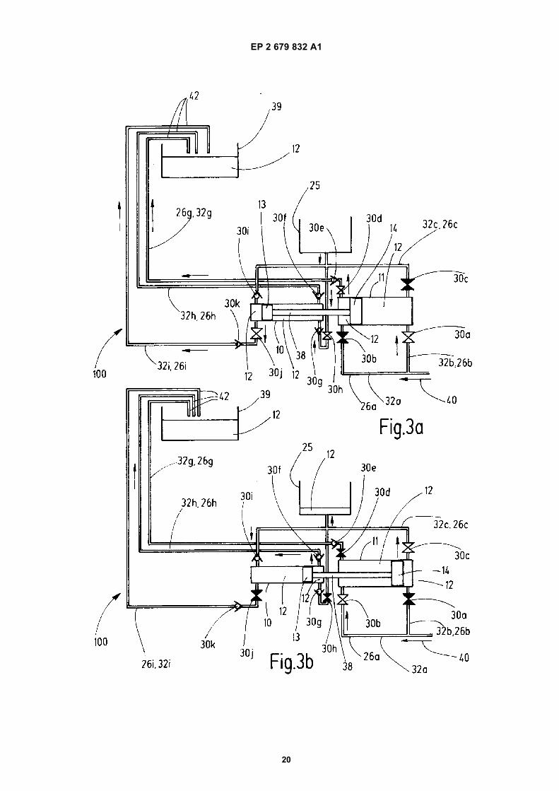
EP 2 679 832 A1
20

EP 2 679 832 A1
21

EP 2 679 832 A1
22

EP 2 679 832 A1
23

EP 2 679 832 A1
24

EP 2 679 832 A1
25
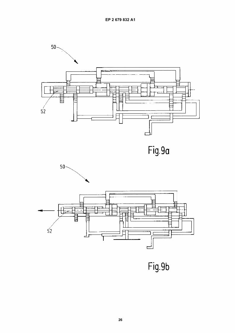
EP 2 679 832 A1
26

EP 2 679 832 A1
27

EP 2 679 832 A1
28


