EON Pressfi t - Axon’ Cable · >> Pressfi t insertion rules >> Climatic & vibration test In...
6
EON Pressfit Eye Of the Needle GUIDELINE SOLDERLESS INTERCONNECT TECHNOLOGY
Transcript of EON Pressfi t - Axon’ Cable · >> Pressfi t insertion rules >> Climatic & vibration test In...

EON Pressfi tEye Of the Needle
GUIDELINE
SOLDERLESSINTERCONNECTTECHNOLOGY
© 2016, AXON’ MECHATRONICS - RELEASED SEPTEMBER 2016 - ALL RIGHTS RESERVED - PHOTOS : NICKELKROME
DOCPAGEAPAGE.indd 2 22/06/2017 11:14:49
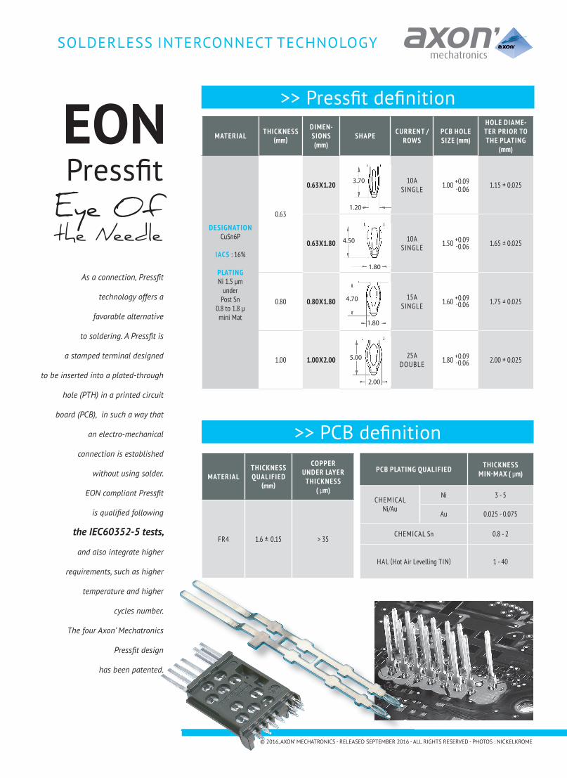
As a connection, Pressfi t
technology offers a
favorable alternative
to soldering. A Pressfi t is
a stamped terminal designed
to be inserted into a plated-through
hole (PTH) in a printed circuit
board (PCB), in such a way that
an electro-mechanical
connection is established
without using solder.
EON compliant Pressfi t
is qualifi ed following
the IEC60352-5 tests,
and also integrate higher
requirements, such as higher
temperature and higher
cycles number.
The four Axon’ Mechatronics
Pressfi t design
has been patented.
>> Pressfi t defi nition
MATERIAL THICKNESS(mm)
DIMEN-SIONS(mm)
SHAPE CURRENT / ROWS
PCB HOLE SIZE (mm)
HOLE DIAME-TER PRIOR TO THE PLATING
(mm)
DESIGNATIONCuSn6P
IACS : 16%
PLATINGNi 1.5 µm
underPost Sn
0.8 to 1.8 µmini Mat
0.63
0.63X1.20 10ASINGLE 1.00 +0.09 1.15 ± 0.025
0.63X1.80 10ASINGLE 1.50 +0.09 1.65 ± 0.025
0.80 0.80X1.80 15ASINGLE 1.60 +0.09 1.75 ± 0.025
1.00 1.00X2.00 25ADOUBLE 1.80 +0.09 2.00 ± 0.025
>> PCB defi nition
MATERIALTHICKNESSQUALIFIED
(mm)
COPPER UNDER LAYER
THICKNESS( µm)
FR4 1.6 ± 0.15 > 35
PCB PLATING QUALIFIED THICKNESSMIN-MAX ( µm)
CHEMICALNi/Au
Ni 3 - 5
Au 0.025 - 0.075
CHEMICAL Sn 0.8 - 2
HAL (Hot Air Levelling TIN) 1 - 40
SOLDERLESS INTERCONNECT TECHNOLOGY
3.70
1.20
1.80
4.50
4.70
1.80
5.00
2.00
EONPressfi tEye Of the Needle
-0.06
-0.06
-0.06
-0.06
© 2016, AXON’ MECHATRONICS - RELEASED SEPTEMBER 2016 - ALL RIGHTS RESERVED - PHOTOS : NICKELKROME
DOCPAGEAPAGE.indd 4 22/06/2017 11:14:59

>> Pressfi t insertion rules
>> Climatic & vibration test
In order to get best performance using Axon’ Mechatronics Pressfi t, we recommend following instructions
The electrical comportment is qualifi ed by the variation of contact resistances, before and after tests. All the tests are carried out one after the other, each test changing the contact resistance (increase or decrease). This variation between each test shall not exceed +0,50mΩ according to IEC 60352.
PRESSFIT(mm)
PCBPLATING
MAX INITIAL CONTACT
RESISTANCE ( mΩ)
MAX CONTACT VARIATION BEFORE/ AFTER TEST
MAX FINALCONTACT
RESISTANCE( mΩ)
VIBRATION
10 Hz to 500 Hz15 mn each direction
12 cycles
THERMAL SHOCK
-40°C to 125°C> 300 H
300 cycles
CLIMATICSEQUENCE
-40°C to 125°C5 cycles of 24 hours
DRY HEAT
125°C / 1008 H
CORROSION
H2S: 100 ±2010-9 VOL/VOLSO2: 500 ± 10010-9 VOL/VOL
0.63 X 1.20
HAL 0.61 0.08 0.08 0.01 0.00 0.02 0.61
Ni/Au 0.73 0.06 0.06 0.02 0.02 0.05 0.65
Sn 0.77 0.05 0.02 0.00 0.01 0.01 0.66
0.63 X 1.80
HAL 0.73 0.08 0.04 0.06 0.00 0.02 0.62
Ni/Au 0.87 0.26 0.03 0.02 0.01 0.05 0.63
Sn 0.77 0.06 0.03 0.00 0.02 0.01 0.61
0.80 X 1.80
HAL 0.65 0.08 0.05 0.05 0.00 0.04 0.63
Ni/Au 0.56 0.26 0.04 0.04 0.00 0.03 0.62
Sn 0.62 0.06 0.02 0.01 0.01 0.00 0.61
1.00 X 2.00
HAL 0.24 0.01 0.04 0.03 0.06 0.02 0.22
Ni/Au 0.22 0.04 0.03 0.01 0.00 0.02 0.23
Sn 0.22 0.01 0.01 0.01 0.00 0.00 0.21
SOLDERLESS INTERCONNECT TECHNOLOGY
R : distance from the through hole center without any component top and bottom sideD1, D2 : minimum distance between 2 Pressfi t through hole center
Note: for specifi c applica-tions (like Pressfi t mounted into connectors), the 0.90 ±0.25 specifi ed distance between PCB and Pressfi t shoulder may be reviewed.
PLEASE CONTACT US FOR FURTHER INFOR-MATION.
◀◀
PRESSFIT(mm)
R(mm)
D1(mm)
D2(mm)
FUNCTIONAL AREA (mm)
0.63 X 1.20 2.5 2.5 2.2 2.03
0.63 X 1.80 3.0 3.0 2.54 2.16
0.80 X 1.80 3.0 3.0 2.54 2.17
1.00 X 2.00 - - - 2.36
© 2016, AXON’ MECHATRONICS - RELEASED SEPTEMBER 2016 - ALL RIGHTS RESERVED - PHOTOS : NICKELKROME © 2016, AXON’ MECHATRONICS - RELEASED SEPTEMBER 2016 - ALL RIGHTS RESERVED - PHOTOS : NICKELKROME
D2minimum
D1minimum
RNO PATTERN
IN THIS DIRECTION
DOCPAGEAPAGE.indd 5 22/06/2017 11:15:00

>> Pressfi t insertion machine
>> Applications
>> Cross sectionOne of the most interesting points of the Pressfi t EON (Eye Of the Needle) technology is the low distortion of the hole.
In some applications, the insertion of single pins replaces molded or overmolded connectors to reduce cost, weight and volume of the system. In this case, the connector housing is moved into the fi nished product cover.
Axon’ Mechatronics offers a wide range of semi-automatic and automa-tic insertion machines for inserting Pressfi t connections into the PCB. These standalone or inline machines can be integrated into electronic PCB manufacturing processes.
To ensure optimum quality, our inser-tion machines integrate options to ensure good Pressfi t insertion such as vision and force monitoring sensors.
Axon’ Mechatronics offers compliant pins for a wide range of applications in different in-dustries.
From inserted terminals onto PCB to stitched or overmoulded connectors, our solderless solutions will fi nd their applications into your demanding product.
Advantages of EON Compliant Pin Designs:
• Environmental compliance - lead-free plating • No separate soldering process necessary• Low thermal stress• Suitable for multilayer and double-sided PCBs• Reliable gas-tight connection, no corrosion• Reliable performance in vibration and shock• Connector can use standard plastic material for cost saving
Press-indirection
Location of themicrosection0.
3+0.2
-0.1
Original holecontour
Measurement of the deformation
a
b
Location of themicrosection
bd
cIEC 141/01
PRESSFIT(mm) a b c d
IEC 60352 < 70 µm > 8 µm < 40 µm NO CRACK
0.63 X 1.20 60 20 0 NO CRACK
0.63 X 1.80 34 28 0 NO CRACK
0.80 X 1.80 65 11 0 NO CRACK
1.00 X 2.00 69 36 0 NO CRACK
PCB
SOLDERLESS INTERCONNECT TECHNOLOGY
© 2016, AXON’ MECHATRONICS - RELEASED SEPTEMBER 2016 - ALL RIGHTS RESERVED - PHOTOS : NICKELKROME
DOCPAGEAPAGE.indd 1 22/06/2017 11:14:47

>> Mechanical properties
MAX PUSH-IN FORCE MIN PUSH-OUT FORCE TERMINAL REPLACEMENT
PRESSFIT : 0.63 X 1.20 mm
PRESSFIT : 0.63 X 1.80 mm
PRESSFIT : 0.80 X 1.80 mm
PRESSFIT : 1.00 X 2.00 mm
020406080
100120
0,85 0,9 0,95 1 1,05 1,1 1,15
HAL
Ni/Au
Sn
F (N
)
Hole diameter (mm)
020406080
100120140
1,35 1,4 1,45 1,5 1,55 1,6 1,65
HAL
Ni/Au
Sn
F (N
)
Hole diameter (mm)
0
10
20
30
40
50
0,85 0,9 0,95 1 1,05 1,1 1,15
HAL
Ni/Au
Sn
F (N
)
Hole diameter (mm)
0
10
20
30
40
1,35 1,4 1,45 1,5 1,55 1,6 1,65
HAL
Ni/Au
Sn
F (N
)
Hole diameter (mm)
HAL
Ni/Au
Sn
F (N
)
Hole diameter (mm)
0
20
40
60
80
1,45 1,5 1,55 1,6 1,65 1,7 1,75
HAL
Ni/Au
Sn
F (N
)
Hole diameter (mm)
050
100150200250300
1,65 1,7 1,75 1,8 1,85 1,9 1,95
0,0010,0020,0030,0040,0050,0060,0070,00
HAL Sn Ni/Au
F (N
)
Hole diameter (mm)
1st insertion
3rd insertion
1st extraction
3rd extraction
0,00
20,00
40,00
60,00
80,00
100,00
HAL Sn Ni/Au
F (N
)
Hole diameter (mm)
1st insertion
3rd insertion
1st extraction
3rd extraction
0,0050,00
100,00150,00200,00250,00300,00350,00400,00
HAL Sn Ni/Au
F (N
)
Hole diameter (mm)
1st insertion
3rd insertion
1st extraction
3rd extraction
0,0020,0040,0060,0080,00
100,00120,00140,00
HAL Sn Ni/Au
F (N
)
Hole diameter (mm)
1st insertion
3rd insertion
1st extraction
3rd extraction
0
50
100
150
200
1,45 1,5 1,55 1,6 1,65 1,7 1,75
HAL
Ni/Au
Sn
F (N
)
Hole diameter (mm)
0
100
200
300
400
500
1,65 1,7 1,75 1,8 1,85 1,9 1,95
HAL
Ni/Au
Sn
F (N
)
Hole diameter (mm)
SOLDERLESS INTERCONNECT TECHNOLOGY
© 2016, AXON’ MECHATRONICS - RELEASED SEPTEMBER 2016 - ALL RIGHTS RESERVED - PHOTOS : NICKELKROME © 2016, AXON’ MECHATRONICS - RELEASED SEPTEMBER 2016 - ALL RIGHTS RESERVED - PHOTOS : NICKELKROME
DOCPAGEAPAGE.indd 6 22/06/2017 11:15:04

AXON’ MECHATRONICS S.A.S.DIVISION LOUPOT
103 avenue de Ty BosCS 45035
29556 QUIMPER CEDEX 09 - FRANCETEL.: +33 2 98 65 66 67FAX: +33 2 98 90 19 17
e-mail: [email protected]
STAMPING ◀
MOULDING ◀
OVERMOULDING ◀
ASSEMBLING ◀
MECHATRONICS ◀
MACHINES ◀
© 2
016,
AXO
N’ M
ECH
ATRO
NIC
S - R
ELEA
SED
SEP
TEM
BER
2016
- AL
L RI
GHTS
RES
ERVE
D -
PHO
TOS
: NIC
KELK
ROM
E
Visit our websitewww.axon-cable.com
FOLLOW US
DOCPAGEAPAGE.indd 3 22/06/2017 11:14:55