ENVIRONMENTAL IMPACT REPORT FOR THE C3 …
63
ENVIRONMENTAL IMPACT REPORT FOR THE C3 STABILIZATION PROJECT A PROJECT FOR SASOL SYNFUELS (PTY) LTD 1 SEPTEMBER 2010
Transcript of ENVIRONMENTAL IMPACT REPORT FOR THE C3 …

ENVIRONMENTAL IMPACT REPORT FOR THE
C3 STABILIZATION PROJECT A PROJECT FOR SASOL SYNFUELS (PTY) LTD
1 SEPTEMBER 2010

ENVIRONMENTAL IMPACT REPORT FOR THE C3 STABILIZATION PROJECT
E02.PTA.000281 31/08/2010 SASOL SYNFUELS (PTY) LTD 1
I
DOCUMENT DESCRIPTION Client: SASOL SYNFUELS (PTY) LTD Report name: ENVIRONMENTAL IMPACT REPORT FOR THE C3
STABILIZATION PROJECT Report type: ENVIRONMENTAL IMPACT REPORT Project name: C3 STABILIZATION PROJECT Bohlweki-SSI Project number: E02.PTA.000281 Document number: 1 Authority Reference: 17/2/2/1(j) GS01 Version: 2 Compiled by: Author (s) Date / location Signature Prashika Reddy 20/08/10
Pretoria
Reviewer Malcolm Roods 23/08/10
Woodmead
Approval Malcolm Roods 23/08/10
Woodmead
ENVIRONMENTAL IMPACT REPORT FOR THE C3 STABILIZATION PROJECT
E02.PTA.000281 31/08/2010 SASOL SYNFUELS (PTY) LTD 1
II
TABLE OF CONTENTS 1 INTRODUCTION ........................................................................................................................... 1
1.1 Need and Background ........................................................................................................... 1 1.2 Approach to the EIA Studies ................................................................................................. 1
1.1.1 Environmental Scoping Study .......................................................................................... 2 1.1.2 Environmental Impact Assessment Study ....................................................................... 2
1.3 Details of the Environmental Assessment Practitioner ......................................................... 2 1.4 Structure of this Report .......................................................................................................... 3
2 PROJECT DESCRIPTION ............................................................................................................ 4 2.1 Location ................................................................................................................................. 4 2.2 Current Operations ................................................................................................................ 4 2.3 Feed to FT Depropaniser ...................................................................................................... 5 2.4 Feed to CatPoly ..................................................................................................................... 5 2.5 Existing Propylene HP Storage Sphere ................................................................................ 5 2.6 Proposed Condensate #3 Buffer Tank .................................................................................. 6 2.7 Proposed Propylene Storage Facility .................................................................................... 6 2.8 Utilities ................................................................................................................................... 6 2.9 Access to Site ........................................................................................................................ 6
3 PROJECT ALTERNATIVES .......................................................................................................... 7 3.1 Alternatives – Condensate #3 Buffer Tank............................................................................ 7
3.1.1 Design/Layout Alternatives .............................................................................................. 7 3.1.2 Preferred Site for the Installation of the Condensate #3 Buffer Tank .............................. 8 3.1.3 Alternative Site for the Installation of the Condensate #3 Buffer Tank ............................ 8
3.2 Alternatives – Propylene Storage Facility .............................................................................. 9 3.2.1 Design/Layout Alternatives .............................................................................................. 9 3.2.1.1 Propylene Bullets (Preferred) ........................................................................................... 9 3.2.1.2 Cold Storage Tanks ....................................................................................................... 10 3.2.2 Preferred Site for the Installation of the Propylene Storage Facility .............................. 10 3.2.3 Alternative Site for the Installation of the Propylene Storage Facility ............................ 11
3.3 No-go Alternative ................................................................................................................. 12 3.4 Alternatives assessed in this EIA Study .............................................................................. 12
3.4.1 Condensate #3 Buffer Tank ........................................................................................... 12 3.4.2 Propylene Storage Facility ............................................................................................. 12
4 GENERAL DESCRIPTION OF THE STUDY AREA ................................................................... 13 4.1 Geology ................................................................................................................................ 13 4.2 Topography and Soils .......................................................................................................... 13 4.3 Geohydrology (Groundwater) .............................................................................................. 13
4.3.1 Groundwater Quality ...................................................................................................... 13 4.4 Hydrology (Surface Water) .................................................................................................. 14
4.4.1 Surface Water Quality .................................................................................................... 14 4.5 Climate and Local Weather Condition ................................................................................. 14
4.5.1 Atmospheric Stability ...................................................................................................... 17 4.5.2 Precipitation .................................................................................................................... 18 4.5.3 Temperature and Humidity............................................................................................. 19
4.6 Biodiversity (Fauna and Flora) ............................................................................................ 21 4.7 Air Quality ............................................................................................................................ 22
4.7.1 Identified Sensitive Receptors ....................................................................................... 22 4.8 Noise .................................................................................................................................... 22 4.9 Social ................................................................................................................................... 22 4.10 Land Use .............................................................................................................................. 23 4.11 Health and Safety ................................................................................................................ 23 4.12 Heritage ............................................................................................................................... 24

ENVIRONMENTAL IMPACT REPORT FOR THE C3 STABILIZATION PROJECT
E02.PTA.000281 31/08/2010 SASOL SYNFUELS (PTY) LTD 1
III
5 ENVIRONMENTAL IMPACT ASSESSMENT METHODOLOGY AND APPROACH ................. 25 5.1 Approach to Undertaking the Study .................................................................................... 25 5.2 Environmental Scoping Study ............................................................................................. 25 5.3 Authority Consultation .......................................................................................................... 25
5.3.1 Consultation with Decision-Making Authority................................................................. 25 5.4 Environmental Impact Assessment ..................................................................................... 26
5.4.1 Methodology – Assessment of Impacts ......................................................................... 26 5.4.2 Impact Assessment Methodology .................................................................................. 26
5.5 EIA Report - EIR .................................................................................................................. 28 5.6 Draft Environmental Management Plan .............................................................................. 29 5.7 Assumptions and Limitations ............................................................................................... 30
6 PUBLIC PARTICIPATION PROCESS ........................................................................................ 31 6.1 Overview of the Public Participation Process ...................................................................... 31
6.1.1 Consultation with Relevant Authorities and Key Stakeholders ...................................... 31 6.1.2 Advertising ...................................................................................................................... 31 6.1.3 Identification of and Consultation with Key Stakeholders .............................................. 32 6.1.4 I&AP Database ............................................................................................................... 32 6.1.5 Consultation and Public Involvement ............................................................................. 32 6.1.6 Issues Trail ..................................................................................................................... 32 6.1.7 Public Review of the Draft Environmental Impact Report ............................................. 32 6.1.8 Authority Review of the Environmental Impact Report .................................................. 33 6.1.9 Environmental Authorisation .......................................................................................... 33
7 CONSTRUCTION PHASE IMPACTS ......................................................................................... 34 7.1 Construction Phase Impacts ................................................................................................ 34
7.1.1 Erosion during Site Clearing .......................................................................................... 34 7.1.2 Dust ................................................................................................................................ 34 7.1.3 Impacts on Water Resources (Ground and Surface Water) .......................................... 35 7.1.4 Impact on Fauna and Flora ............................................................................................ 35 7.1.5 Noise Pollution ............................................................................................................... 35 7.1.6 Waste Pollution .............................................................................................................. 35 7.1.7 Health and Safety ........................................................................................................... 36 7.1.8 Social Impacts ................................................................................................................ 36
8 OPERATIONAL PHASE IMPACTS ............................................................................................. 40 8.1 Safety during Operation and Maintenance .......................................................................... 40
8.1.1 Condensate #3 Buffer Tank ........................................................................................... 41 8.1.2 Propylene Storage Vessels ............................................................................................ 42 8.1.2.1 Mitigation and Recommendations .................................................................................. 43
8.2 Impact on Air Quality ........................................................................................................... 43 8.2.1 Model Overview .............................................................................................................. 44 8.2.2 Model Requirements ...................................................................................................... 44 8.2.3 Emissions Inventory ....................................................................................................... 44 8.2.3.1 SCC Flare ....................................................................................................................... 44 8.2.3.2 Pressure Bullets ............................................................................................................. 45 8.2.4 Impact Assessment ........................................................................................................ 46 8.2.5 Mitigation and Recommendations .................................................................................. 49
8.3 Impact on Water Resources ................................................................................................ 50 8.4 Waste Impacts ..................................................................................................................... 50 8.5 Cumulative Impacts ............................................................................................................. 50
9 DECOMMISSIONING PHASE IMPACTS ................................................................................... 54 10 CONCLUSIONS AND RECOMMENDATIONS ...................................................................... 55
10.1 Evaluation of the Proposed Project ..................................................................................... 55 10.1.1 Condensation #3 Buffer Tank – ..................................................................................... 55 10.1.2 Propylene Storage Facility ............................................................................................. 56

ENVIRONMENTAL IMPACT REPORT FOR THE C3 STABILIZATION PROJECT
E02.PTA.000281 31/08/2010 SASOL SYNFUELS (PTY) LTD 1
IV
10.2 Concluding Remarks ........................................................................................................... 56 10.3 Final Recommendations ...................................................................................................... 56
APPENDICES
APPENDIX A ACCEPTANCE OF APPLICATION (MDEDET) APPENDIX B PLOT PLAN LAYOUT – BUFFER TANK APPENDIX C PLOT PLAN LAYOUT – PROPYLENE BULLETS APPENDIX D PUBLIC NOTIFICATIONS APPENDIX E I&AP DATABASE AND ISSUES TRAIL APPENDIX F CONSEQUENCE IMPACT STUDY APPENDIX G AIR QUALITY IMPACT ASSESSMENT APPENDIX H ENVIRONMENTAL MANAGEMENT PLAN
LIST OF FIGURES Figure 1: Overview of the C3 Value Chain ........................................................................................... 5Figure 2: Block flow diagram of the C3 value chain and proposed new infrastructure ........................ 7Figure 3: Preferred area for the installation of the Condensate #3 buffer tank in the SCC plant ........ 8Figure 4: Alternative site for Condensate #3 in the HP tank farm ........................................................ 9Figure 5: Example of propylene storage bullets ................................................................................. 10Figure 6: Preferred site for the placement of the propylene store (red block) .................................... 11Figure 7: Alternative site – new tank farm for the installation of the propylene store ........................ 12Figure 8: Period wind rose for the Sasol Club and Langverwacht. .................................................... 15Figure 9: Diurnal wind roses for the Sasol Club Monitoring Station ................................................... 16Figure 10: Diurnal wind roses for the Langverwacht Monitoring Station ............................................ 17Figure 11: Stability class frequency distribution for Sasol Club and Langverwacht ........................... 18Figure 12: Average monthly rainfall at the Sasol Club. (2006) ........................................................... 19Figure 13: Average monthly rainfall at Langverwacht (2006) ............................................................. 19Figure 14: Average monthly temperatures and humidity recorded at Sasol Club ............................. 20Figure 15: Average monthly temperatures and humidity recorded at Sasol Langverwacht .............. 21Figure 16: Explosion overpressure distances at the buffer vessel due to a 50 mm leak ................... 41Figure 17: Explosion overpressure distances due to a 50 mm leak at a confined space (2 vessels) 42Figure 18: Explosion overpressure distances due to a 50 mm leak at a confined space .................. 43Figure 19: Hourly average predicted ground level concentrations - SCC flare .................................. 46Figure 20: Daily average predicted ground level concentrations - SCC Flare ................................... 47Figure 21: Annual average predicted ground level concentrations – SCC Flare ............................... 48Figure 22: Annual average predicted ground level concentrations (µg/m3) for the proposed tanks .. 49
LIST OF TABLES Table 1: Details of the EAP ................................................................................................................... 3Table 2: Report Structure ...................................................................................................................... 3Table 3: Atmospheric Stability Classes .............................................................................................. 17Table 4: Identified Sensitive Receptors in the Study Area ................................................................. 22Table 5: Criteria used for the rating of impacts ................................................................................... 27Table 6: Criteria for the rating of classified impacts ........................................................................... 28Table 7: Assessment of the Potential Impacts during the Construction Phase of the Condensate #3
tank at the SCC Plant (Preferred) ........................................................................................... 37Table 8: Assessment of the Potential Impacts during the Construction Phase of the Condensate #3
tank at the HP Tank Farm ...................................................................................................... 38Table 9: Average points allocated to the different site alternatives for the buffer tank ...................... 39

ENVIRONMENTAL IMPACT REPORT FOR THE C3 STABILIZATION PROJECT
E02.PTA.000281 31/08/2010 SASOL SYNFUELS (PTY) LTD 1
V
Table 10: Assessment of the Potential Impacts during the Construction Phase of the Propylene Storage Facility west of PP2 plant .......................................................................................... 39
Table 11: Consequences applicable to different overpressures ........................................................ 40Table 12: Source parameters for the SCC flare ................................................................................. 45Table 13: Current emission rates for the SCC flare ........................................................................... 45Table 14: Source parameters for the pressure bullets ....................................................................... 45Table 15: Emission rates for the pressure bullets (as calculated using Tanks) ................................. 45Table 16: Assessment of the potential impacts during the Operational Phase – Condensate #3
Buffer Tank ............................................................................................................................. 51Table 17: Assessment of the potential impacts during the Operational Phase – Propylene Bullets
(Preferred) ............................................................................................................................... 51Table 18: Assessment of the potential impacts during the Operational Phase – Cold Storage Tanks
............................................................................................................................................................. 52Table 19: Average points allocated to the different design alternatives for the propylene store ....... 52Table 20: Assessment of cumulative impacts during the Operational Phase .................................... 53 ABBREVIATIONS CatPoly Catalytic Polymerisation Plant EAP Environmental Assessment Practitioner EIA Environmental Impact Assessment EMP Environmental Management Plan ESS Environmental Scoping Study FT Fischer Tropsch HAZOP Hazard Operability HP High Pressure I&AP Interested and Affected Party MDEDET Mpumalanga Department of Economic Development, Environment and
Tourism NEMA National Environmental Management Act (Act No 107 of 1998), as amended PP Polypropylene Plant PP1 Polypropylene Plant 1 PP2 Polypropylene Plant 2 PPU Propylene Purification Units SCC Synfuels Catalytic Cracker

ENVIRONMENTAL IMPACT REPORT FOR THE C3 STABILIZATION PROJECT
E02.PTA.000281 31/08/2010 SASOL SYNFUELS (PTY) LTD 1
1
1 INTRODUCTION Large volumes of propylene rich feedstock are currently bypassing the Propylene Purification Units (PPUs) and the Fischer Tropsch (FT) Depropaniser at Synfuels Catalytic Cracker (SCC). All the material on bypass is routed to the Catalytic Polymerization (or CatPoly) units, which results in a very unstable feed to CatPoly, both in volume and propylene content. Sasol Synfuels therefore proposes to de-link the extremely tight integration between the upstream Synthol reactors, propylene extraction units and the downstream chemical plants via appropriate storage facilities. It is proposed to install a buffer tank to stabilise the propylene rich feedstock to the PPUs and FT Depropaniser and ensure proper extraction without the need to bypass valuable chemical feedstock to Catpoly. Downstream of the PPUs and FT Depropaniser, the existing extracted propylene storage sphere is also too small to buffer the current imbalance between the supply and demand of extracted propylene. Any excess propylene is diverted to CatPoly when the sphere is full. A bigger extracted propylene storage facility is therefore necessary. Less propylene will be diverted to CatPoly and the production of high value propylene will increase. 1.1 Need and Background Condensate 3 is routed to the Propylene Purification Unit number 1 (PPU1, or Unit 70) and Propylene Purification Unit number 2 (PPU2, or Unit 285) for propylene extraction. Since the Condensate 3 stream flow rate is too high and fluctuating severely, some of this condensate is bypassed around these two PPUs. The propane rich bottom streams from PPU1 and PPU2, together with the Condensate 3 that was bypassed, is then routed to the FT de-propanizer #1 unit at the SCC plant. The overhead stream from this column, consisting of propylene and propane, is then routed to PPU5 for further propylene extraction. The C3 value chain, as described above, is at present inherently unstable. This system instability leads to significant operational problems in the value chain as well as huge financial losses. An opportunity therefore exists to optimise the propylene value chain in Secunda. The project will also result in 10000 ton/year less propylene being flared resulting in a positive impact on air quality. The end result of this optimisation will be to maximise propylene extraction from the fuel pool into higher value adding chemicals. 1.2 Approach to the EIA Studies The environmental impacts associated with the proposed project require investigation in compliance with the Environmental Impact Assessment Regulations (2006) published in Government Notice No. R. 385 to No. R. 387 and read with Section 24 (5) of the National Environmental Management Act - NEMA (Act No 107 of 1998) (as amended). The required environmental studies include the undertaking of an Environmental Impact Assessment (EIA) process. This process is being undertaken in two phases: • Phase 1 - Environmental Scoping Study (ESS); and • Phase 2 - Environmental Impact Assessment (EIA) and Environmental Management Plan
(EMP).
ENVIRONMENTAL IMPACT REPORT FOR THE C3 STABILIZATION PROJECT
E02.PTA.000281 31/08/2010 SASOL SYNFUELS (PTY) LTD 1
2
1.1.1 Environmental Scoping Study The ESS provided a description of the receiving environment and how the environment may be affected by the development of the proposed project. Desktop studies making use of existing information, and ground-truthing through site visits, were used to highlight and assist in the identification of potential significant impacts (both social and biophysical) associated with the proposed project. Additional issues for consideration were extracted from feedback from the public participation process, which commenced at the beginning of the Scoping phase, and will continue throughout the duration of the project. All issues identified during the ESS were documented within the Environmental Scoping Report. The final Environmental Scoping Report (ESR) and Plan of Study for EIA were submitted to the Mpumalanga Department of Economic Development, Environment and Tourism (MDEDET) in June 2010. The final ESR and Plan of Study for EIA were accepted by the MDEDET in a letter dated 29 July 2010 (Appendix A). This draft Environmental Impact Report (EIR) has been compiled in accordance with the accepted Plan of Study and incorporates the findings and recommendations from the Scoping Study as well as specialist studies conducted for the project. 1.1.2 Environmental Impact Assessment Study The Environmental Impact Assessment phase will aim to achieve the following: • to provide an overall assessment of the social and biophysical environments of the affected
area by the proposed C3 stabilization project; • to undertake a detailed assessment of the preferred site/s in terms of environmental criteria
including the rating of significant impacts; • to identify and recommend appropriate mitigation measures (to be included in an EMP) for
potentially significant environmental impacts; and • to undertake a fully inclusive public participation process to ensure that I&AP issues and
concerns are recorded and commented on and addressed in the EIA process. 1.3 Details of the Environmental Assessment Practitioner Bohlweki-SSI Environmental (Bohlweki-SSI) has been appointed as an independent Environmental Assessment Practitioner (EAP) by Sasol Synfuels, to undertake the appropriate environmental studies for this proposed project. The professional team of Bohlweki-SSI has considerable experience in the environmental management and EIA fields. Bohlweki-SSI has been involved in and/or managed several of the largest Environmental Impact Assessments undertaken in South Africa to date. A specialist area of focus is on the assessment of multi-faceted projects, including the establishment of linear developments (national and provincial roads, and power lines), bulk infrastructure and supply (e.g. wastewater treatment works, pipelines, landfills), electricity generation and transmission, the mining industry, urban, rural and township developments, environmental aspects of Local Integrated Development Plans (LIDPs), as well as general environmental planning, development and management.

ENVIRONMENTAL IMPACT REPORT FOR THE C3 STABILIZATION PROJECT
E02.PTA.000281 31/08/2010 SASOL SYNFUELS (PTY) LTD 1
3
The particulars of the EAP are presented in Table 1 below: Table 1: Details of the EAP Consultant: Bohlweki-SSI Environmental Contact Persons: Prashika Reddy and Malcolm Roods Postal Address PO Box 867
Gallo Manor 2052
Telephone: 012 367 5973 / 011 798 6442 Facsimile: 012 367 5878 / 011 798 6010 E-mail: [email protected] / [email protected] Expertise: Prashika Reddy is an Associate / Senior Environmental Scientist (Pr Sci Nat
400133/10) with a BSc Honours in Geography. Ms Reddy has the necessary experience in various environmental fields including: environmental impact assessments, environmental management plans/programmes, public participation and environmental monitoring and auditing. Ms Reddy has extensive experience in compiling environmental reports (Screening, Scoping, EIA and Status Quo Reports). Ms Reddy is/has been part of numerous multi-faceted large–scale projects, including the establishment of linear developments (roads, and power lines); industrial plants; electricity generation plants and mining-related projects.
1.4 Structure of this Report Table 2: Report Structure
CHAPTER CONTENT Chapter 1 – Introduction Introduction to project and approach to the Environmental
Impact Assessment Study Chapter 2 - Project Description Provides the technical description of the project as well as
a description of the infrastructure Chapter 3 - Project Alternatives Description and comparative assessment of all identified
during the environmental impact process Chapter 4 - General Description of the Study Area
A description of the biophysical and social environment
Chapter 5 – Environmental Impact Assessment Methodology and Approach
Methodology used in the assessment of significant impacts
Chapter 6 - Public Participation Process
Overview of the public participation process conducted to date
Chapter 7 – Construction Phase Impacts
A description and assessment of construction phase impacts
Chapter 8 – Operational Phase Impacts
A description and assessment of operational phase impacts
Chapter 9 – Decommissioning Phase Impacts
A description and assessment of decommissioning phase impacts
Chapter 10 - Conclusions and Recommendations
Conclusions and recommendations of the Environmental Impact Study

ENVIRONMENTAL IMPACT REPORT FOR THE C3 STABILIZATION PROJECT
E02.PTA.000281 31/08/2010 SASOL SYNFUELS (PTY) LTD 1
4
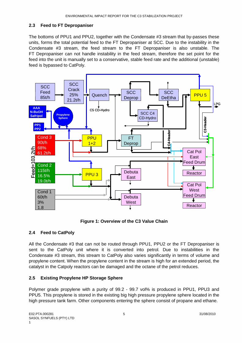
2 PROJECT DESCRIPTION 2.1 Location The proposed project is confined to the boundaries of the Sasol Synfuels Secunda Complex. The area is part of Extension 35 of Secunda and more specifically Erf 8488. The installation of the buffer tank near the SCC plant (S 26°33’16.1’’; E 29°09’39.3’’) will take place in the primary area of the complex whilst the propylene storage facility (S 26°33’10.0’’; E 29°11’01.1’’) will be installed in the secondary area. The nearest town, Secunda, is approximately 5 km away from the complex while the Embalenhle community is approximately 10 km away from the complex. 2.2 Current Operations Condensate #1, #2 and #3 from U23 and U223 (Cold Separation) enters the C3 value chain where the propylene is extracted at the PPUs. Condensate #1 that contains ± 3% propylene is sent directly to the CatPoly units, without any propylene being extracted (refer Figure 1). Condensate #2 that contains ± 16.5% propylene is routed through PPU3 (U288) where the propylene is extracted at 99.2 – 99.5% purity and stored in the propylene sphere. The bottoms of PPU3, together with the Condensate #2 portion that bypasses the unit (due to capacity constraints), is sent to CatPoly for conversion (refer to Figure 1). Condensate #3 contains ± 68% propylene and is sent in parallel to PPU1 and PPU2 for propylene extraction. PPU1 and PPU5 are operated in series to increase the propylene extraction from the Condensate #3 stream. The purity of the extracted propylene is 99.2 – 99.7%. Currently PPU2 is only on line during the periods that PPU5 is off line for a shut down. This is due to PPU2 producing chemical grade propylene (95% purity) and the extraction capacity of PPU1 and PPU5 being sufficient at the current flow rates (refer to Figure 1). PPU1 is filled to capacity with Condensate #3 while the rest of the Condensate #3 stream by-passes this unit. This Condensate #3 by-pass stream together with the bottoms from PPU1 and PPU2 (if it is running), forms the feed stream to the FT Depropaniser at SCC. The FT Depropaniser can however not operate efficiently with an unstable feed flow. In an attempt to stabilise the flow to the unit, a portion of this propylene rich feed stream is diverted to the CatPoly units, resulting in a feed stream to CatPoly that varies in volume and propylene content. The product stream from the FT Depropaniser is sent to PPU5 where the balance of the propylene is extracted. Downstream of the extraction units, the extracted propylene is stored in the propylene spheres located in the high pressure tank farm. When PPU2 is on line, the chemical grade propylene from this unit is stored separately from the polymer grade propylene extracted at PPU1, 3 and 5. From the spheres the propylene is then supplied to the various clients: • Secunda: Polypropylene Plants (PP1 and PP2) • Sasolburg: AAA, n-Butanol and Safripol.
ENVIRONMENTAL IMPACT REPORT FOR THE C3 STABILIZATION PROJECT
E02.PTA.000281 31/08/2010 SASOL SYNFUELS (PTY) LTD 1
5
2.3 Feed to FT Depropaniser The bottoms of PPU1 and PPU2, together with the Condensate #3 stream that by-passes these units, forms the total potential feed to the FT Depropaniser at SCC. Due to the instability in the Condensate #3 stream, the feed stream to the FT Depropaniser is also unstable. The FT Depropaniser can not handle instability in the feed stream, therefore the set point for the feed into the unit is manually set to a conservative, stable feed rate and the additional (unstable) feed is bypassed to CatPoly.
Cond 390t/h68%61.2t/h
Cond 2115t/h16.5%19.0t/h
Cond 160t/h3%1.8
SCC Crack25%
21.2t/h
PPU 1+2
PPU 3
FT Deprop
PPU 5
DebutaEast
Quench SCC Deprop
SCC DeEtha
SCC Feed85t/h
SCC C4 CD-Hydro
C4-
Hea
der C3-
Hea
der
Cat PolEast
Feed Drum
Cat PolWest
Feed DrumDebutaWest
Propylene Sphere
C5 CD-Hydro
Reactor
Reactor
Feed
=103
.2t/h
LPG
PP1PP2
AAAN-BuOHSafripol
Figure 1: Overview of the C3 Value Chain 2.4 Feed to CatPoly All the Condensate #3 that can not be routed through PPU1, PPU2 or the FT Depropaniser is sent to the CatPoly unit where it is converted into petrol. Due to instabilities in the Condensate #3 stream, this stream to CatPoly also varies significantly in terms of volume and propylene content. When the propylene content in the stream is high for an extended period, the catalyst in the Catpoly reactors can be damaged and the octane of the petrol reduces. 2.5 Existing Propylene HP Storage Sphere Polymer grade propylene with a purity of 99.2 - 99.7 vol% is produced in PPU1, PPU3 and PPU5. This propylene is stored in the existing big high pressure propylene sphere located in the high pressure tank farm. Other components entering the sphere consist of propane and ethane.
ENVIRONMENTAL IMPACT REPORT FOR THE C3 STABILIZATION PROJECT
E02.PTA.000281 31/08/2010 SASOL SYNFUELS (PTY) LTD 1
6
The total capacity of the existing high pressure propylene sphere is 1630 m3. The full volume of this sphere can however not be used as an optimal operating level (950 m3) has to be maintained in order to minimise the risk and impact both to production plants and clients. The maximum operating level for this sphere is 1200 m3, with the absolute maximum level at 1280 m3, leaving 20% vapour space. However, at this level the vapour pressure in the sphere increases to above 1740 kPag and the over pressure valves will open, thus flaring the vapour in order to lower the pressure. 2.6 Proposed Condensate #3 Buffer Tank A stochastic model has been built to simulate the stabilization of the FT Depropaniser #1 feed stream. The results indicated that a vessel with a capacity of 200t to 300t (± 400 m3 to ± 600 m3) liquid volume is required. To compensate for the density and head space a tank of 700 m3 is proposed. 2.7 Proposed Propylene Storage Facility The propylene supply and demand imbalance will be addressed by installing bigger storage capacity of 3000t liquid propylene (± 7500 m3 compensated for density and head space) as determined by means of stochastic modelling. The existing propylene store will stay in the current operation position, forming part of the required 7500 m3 propylene storage.
2.8 Utilities A preliminary utility requirement on the new vessels will be completed in the Pre-Feasibility phase of the project, since the availability and supply of utilities is expected to influence the site selection. The preliminary utility requirement will be based on the preliminary vessel sizing, information regarding utility supply to similar storage facilities and other assumptions.
2.9 Access to Site The proposed site for the condensate #3 buffer storage (next to the SCC site) will be located on the road west of the PPU5 tower, the existing road would therefore be rerouted to ensure proper access for all vehicles and especially emergency vehicle access to the plant. The plot space of the PP2 plant will be extended to include the proposed new propylene storage, all existing roads from the PP2 plant will be extended to allow proper access to all vehicles to the new storage vessels. All access will still be controlled from the main entrance to PP1 and PP2.
ENVIRONMENTAL IMPACT REPORT FOR THE C3 STABILIZATION PROJECT
E02.PTA.000281 31/08/2010SASOL SYNFUELS (PTY) LTD1
7
3 PROJECT ALTERNATIVES
In terms of the EIA Regulations, Section 29 (1)(b) feasible alternatives are required to be considered as part of the environmental investigations. In addition, the obligation that alternatives are investigated is also a requirement of Section 24(4) of the National Environmental Management Act (Act 107 of 1998, NEMA’)(as amended). An alternative in relation to a proposed activity refers to the different means of meeting the general purpose and requirements of the activity (as defined in Government Notice R385 of the EIA Regulations, 2006), which may include alternatives to:a) the property on which or location where it is proposed to undertake the activity;b) the type of activity to be undertaken;c) the design or layout of the activity;d) the technology to be used in the activity; and e) the operational aspects of the activity.
3.1 Alternatives – Condensate #3 Buffer Tank
3.1.1 Design/Layout Alternatives
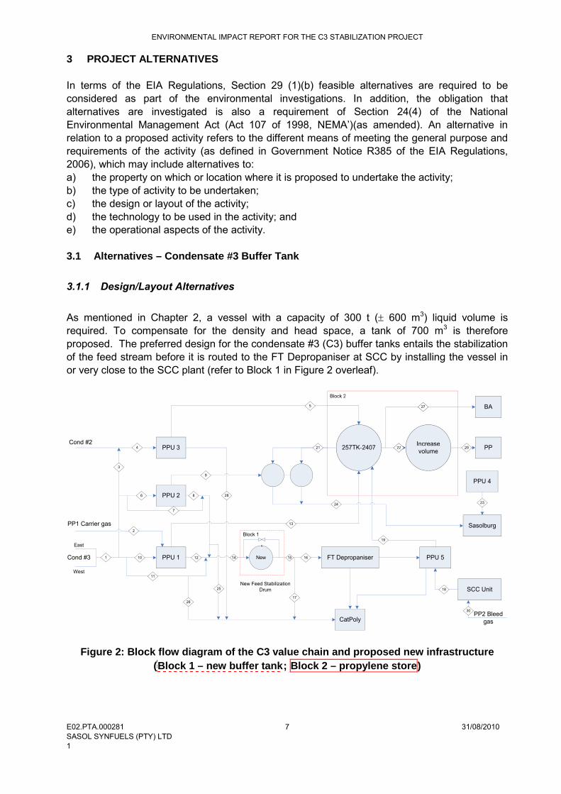
As mentioned in Chapter 2, a vessel with a capacity of 300 t ( 600 m3) liquid volume is required. To compensate for the density and head space, a tank of 700 m3 is therefore proposed. The preferred design for the condensate #3 (C3) buffer tanks entails the stabilizationof the feed stream before it is routed to the FT Depropaniser at SCC by installing the vessel in or very close to the SCC plant (refer to Block 1 in Figure 2 overleaf).
PPU 1
Sasolburg
PPU 3
PPU 5
CatPoly
PP
FT Depropaniser
PPU 2
257TK-2407Cond #2
PP1 Carrier gas
Cond #3
East
West
Block 1
Block 2
New
New Feed Stabilization Drum
PPU 4
SCC Unit
BA
3
1
2
4
5
6
7
8
9
10
11
12
13
14 15 16
17
18
19
21 22
2324
25
26
27
28
Increasevolume
29
c
PP2 Bleedgas
30
257TK-2407
Block 2
22
27
Increasevolume
Figure 2: Block flow diagram of the C3 value chain and proposed new infrastructure (Block 1 – new buffer tank; Block 2 – propylene store)
ENVIRONMENTAL IMPACT REPORT FOR THE C3 STABILIZATION PROJECT
E02.PTA.000281 31/08/2010 SASOL SYNFUELS (PTY) LTD 1
8
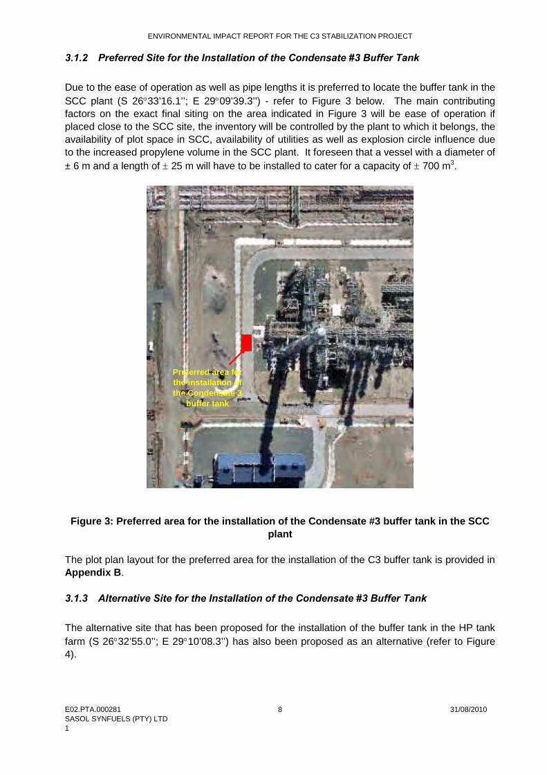
3.1.2 Preferred Site for the Installation of the Condensate #3 Buffer Tank Due to the ease of operation as well as pipe lengths it is preferred to locate the buffer tank in the SCC plant (S 26°33’16.1’’; E 29°09’39.3’’) - refer to Figure 3 below. The main contributing factors on the exact final siting on the area indicated in Figure 3 will be ease of operation if placed close to the SCC site, the inventory will be controlled by the plant to which it belongs, the availability of plot space in SCC, availability of utilities as well as explosion circle influence due to the increased propylene volume in the SCC plant. It foreseen that a vessel with a diameter of ± 6 m and a length of ± 25 m will have to be installed to cater for a capacity of ± 700 m3.
Figure 3: Preferred area for the installation of the Condensate #3 buffer tank in the SCC
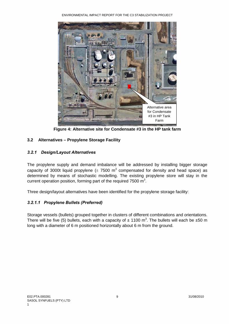
plant The plot plan layout for the preferred area for the installation of the C3 buffer tank is provided in Appendix B. 3.1.3 Alternative Site for the Installation of the Condensate #3 Buffer Tank The alternative site that has been proposed for the installation of the buffer tank in the HP tank farm (S 26°32’55.0’’; E 29°10’08.3’’) has also been proposed as an alternative (refer to Figure 4).
Preferred area for the installation of the Condensate 3
buffer tank
ENVIRONMENTAL IMPACT REPORT FOR THE C3 STABILIZATION PROJECT
E02.PTA.000281 31/08/2010 SASOL SYNFUELS (PTY) LTD 1
9
Figure 4: Alternative site for Condensate #3 in the HP tank farm
3.2 Alternatives – Propylene Storage Facility 3.2.1 Design/Layout Alternatives The propylene supply and demand imbalance will be addressed by installing bigger storage capacity of 3000t liquid propylene (± 7500 m3 compensated for density and head space) as determined by means of stochastic modelling. The existing propylene store will stay in the current operation position, forming part of the required 7500 m3. Three design/layout alternatives have been identified for the propylene storage facility: 3.2.1.1 Propylene Bullets (Preferred) Storage vessels (bullets) grouped together in clusters of different combinations and orientations. There will be five (5) bullets, each with a capacity of ± 1100 m3. The bullets will each be ±50 m long with a diameter of 6 m positioned horizontally about 6 m from the ground.
Alternative area for Condensate #3 in HP Tank
Farm

ENVIRONMENTAL IMPACT REPORT FOR THE C3 STABILIZATION PROJECT
E02.PTA.000281 31/08/2010 SASOL SYNFUELS (PTY) LTD 1
10
Figure 5: Example of propylene storage bullets 3.2.1.2 Cold Storage Tanks Two cold storage tanks with a volume of 3000 m3 each have been considered as an alternative and will be further assessed during this EIA study. 3.2.2 Preferred Site for the Installation of the Propylene Storage Facility The existing propylene sphere is located in the high pressure tank farm due to the pressure that the propylene is stored at. By default, the preferred option for additional propylene storage would have also been in the high pressure tank farm, as close as possible to the existing storage to minimise line lengths and hydraulic impacts on the system. But due to the restricted space in this tank farm, it was necessary to find an alternative site where the propylene storage vessels can be erected. Criteria used to evaluate candidate sites included the availability of utilities, distance from existing storage vessel (again to minimise line lengths and hydraulic impact) and safety concerns (explosion circle modelling to establish impact of increased inventory) as well as operation procedures and inventory control during normal operation. The area west of the PP2 plant has been identified as the preferred site for the installation of the propylene storage facility. This site is next to the pipe route to the PP2 plant (S 26°33’10.0’’; E 29°11’01.1’’) - refer to Figure 6. As the propylene stored in these storage vessels will be mainly supplied to the PP2 plant, it is preferred that the PP2 operations personnel operate these units. All utilities will be investigated during the next phase of the project but it is likely to be supplied from the PP2 site. The plot space required is ± 100 m x 100 m.
ENVIRONMENTAL IMPACT REPORT FOR THE C3 STABILIZATION PROJECT
E02.PTA.000281 31/08/2010 SASOL SYNFUELS (PTY) LTD 1
11
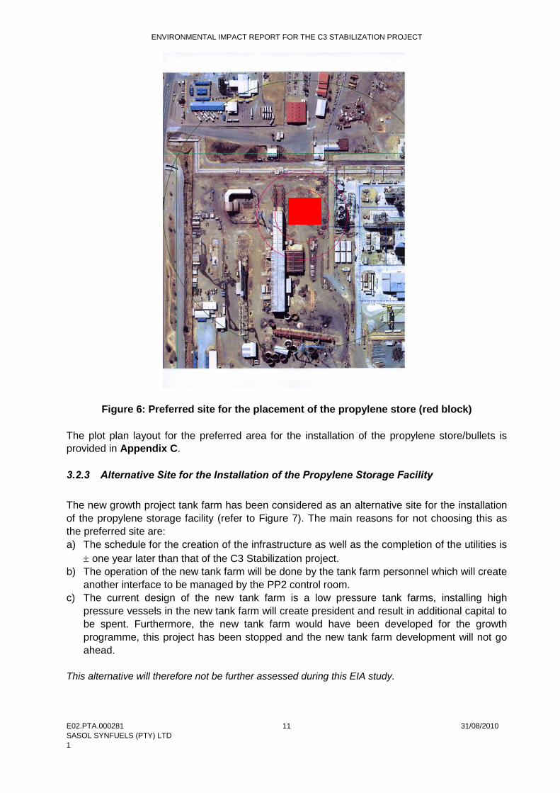
Figure 6: Preferred site for the placement of the propylene store (red block) The plot plan layout for the preferred area for the installation of the propylene store/bullets is provided in Appendix C. 3.2.3 Alternative Site for the Installation of the Propylene Storage Facility The new growth project tank farm has been considered as an alternative site for the installation of the propylene storage facility (refer to Figure 7). The main reasons for not choosing this as the preferred site are: a) The schedule for the creation of the infrastructure as well as the completion of the utilities is
± one year later than that of the C3 Stabilization project. b) The operation of the new tank farm will be done by the tank farm personnel which will create
another interface to be managed by the PP2 control room. c) The current design of the new tank farm is a low pressure tank farms, installing high
pressure vessels in the new tank farm will create president and result in additional capital to be spent. Furthermore, the new tank farm would have been developed for the growth programme, this project has been stopped and the new tank farm development will not go ahead.
This alternative will therefore not be further assessed during this EIA study.

ENVIRONMENTAL IMPACT REPORT FOR THE C3 STABILIZATION PROJECT
E02.PTA.000281 31/08/2010 SASOL SYNFUELS (PTY) LTD 1
12
Figure 7: Alternative site – new tank farm for the installation of the propylene store 3.3 No-go Alternative Presently large volumes of propylene rich feedstock are bypassing the Propylene Purification Units and FT Depropaniser at SCC. All the material is routed to CatPoly units, which results in a very unstable feed to CatPoly both in terms of volume and propylene content. Moreover, the extracted propylene storage sphere is too small to buffer the current imbalance between the supply and demand of extracted propylene. Without the proposed feed stabilization tank and the larger propylene storage, the production of high value polypropylene at the Polypropylene Plants will decrease while increasing the propylene volume going to CatPoly where low octane petrol is produced. Furthermore, without the project, excess propylene (approximately 10000 ton/year) will continued to be flared. 3.4 Alternatives assessed in this EIA Study The following alternatives will therefore be assessed during this EIA study: 3.4.1 Condensate #3 Buffer Tank This report will investigate the installation of one tank (700 m3) at either the SCC plant or at the HP tank farm (i.e. two site alternatives). 3.4.2 Propylene Storage Facility This report will investigate the installation of either five storage vessels (bullets) grouped together in clusters (the vessels will each be a volume of ± 1100 m3) or two cold storage tanks with a volume of 3000 m3 area west of the PP2 plant (i.e. two design alternatives).
Alternative area for
placement of propylene
store in the new tank farm

ENVIRONMENTAL IMPACT REPORT FOR THE C3 STABILIZATION PROJECT
E02.PTA.000281 31/08/2010 SASOL SYNFUELS (PTY) LTD 1
13
4 GENERAL DESCRIPTION OF THE STUDY AREA The proposed C3 Stabilization Project which includes the installation of a buffer tank and construction of a bigger propylene storage unit is to be located within the Sasol Synfuels current area of operation within the Secunda complex. 4.1 Geology Sasol’s Secunda plant is underlain by rocks belonging to the Vryheid Formation of the Ecca Group, Karoo Supergroup. These rocks primarily consist of sandstones, shales and coal beds and are extensively intruded by dolerites of Jurassic age. The dolerites occur both as sills and linear dyke structures that may extend over tens of kilometers. 4.2 Topography and Soils The topography of the greater study area is relatively flat and stable with little agricultural potential. The greater study area falls within the Karoo Supergroup, however the proposed site is highly transformed. The highest point of the site elevation is 1600 m above sea level. Soils in the proposed area have been disturbed with the historical establishment of the Secunda Complex in the 1970’s where the existing soil was replaced with a 1:1 mixture of dolerite and ash. The importation and compaction of fill material has inherently created a near impermeable soil horizon, minimizing the potential for the ingress of contaminants from surface into the underlying subsoil. 4.3 Geohydrology (Groundwater) The groundwater at the Sasol Complex is characterised by two groundwater aquifers, including a weathered aquifer occurring at a depth of between 8 and 14 m below existing ground level, and a fractured rock aquifer occurring at depths greater than 20 m below existing ground level. The weathered aquifer occurs within the weathered shale, siltstone and mudstones of the Karoo Formation, this aquifer consequently has a low permeability of, on average, 0.005 m/day, whereas the fractured rock aquifer has a very low permeability of, on average, 0.0004 m/day. The low permeability’s of the weathered and fractures rock aquifer will limit the movement of contaminants within the groundwater system. Groundwater flows in a northerly direction towards Klipspruit with a relatively low hydraulic gradient of 0.08, based on topographical elevations. 4.3.1 Groundwater Quality Monitoring boreholes located within the factory and to the north of the Klipspruit have indicated the character of the groundwater quality to be dominated by inorganic components, calcium, sodium, nitrate, ammonia, sulphate, iron and manganese. As could be expected, groundwater quality monitoring boreholes in close proximity of contaminant sources reflect localized elevated contaminant levels. Usually, this occurs at a shallow depth of about 5 m. However, it should be noted that background total dissolved concentrations in boreholes within the greater Secunda area could reflect values up to about 850 mg/l.

ENVIRONMENTAL IMPACT REPORT FOR THE C3 STABILIZATION PROJECT
E02.PTA.000281 31/08/2010 SASOL SYNFUELS (PTY) LTD 1
14
It is noted that a 5 km exclusion zone has been established in terms of groundwater abstractive use around the Complex. Consequently there are no direct users of groundwater within the area of potential influence. 4.4 Hydrology (Surface Water) The Sasol Secunda Industrial and Mining Complex is located in the upper reaches of the Waterval River, affecting the following tributaries of this river: • Klein and Groot Bossiespruit • Brandspruit • Klipspruit • Trichardspruit. The above streams combine into the Trichardspruit and after the confluence with the Grootspruit, the Trichardspruit joins the Waterval River. The water quality and flow profile of the Waterval River changed substantially from the time Sasol Industrial and Mining Complex was established in the late 1970’s. A notable portion of the salinity generated in the Waterval River catchment now originates from the Trichardspruit sub-catchment in which the Sasol Secunda Industrial and Mining Complex is located. No surface water bodies occur in the vicinity of the SCC plant, HP tank farm and the area west of the PP2 plant. 4.4.1 Surface Water Quality Sasol Synfuels monitors the quality of water in the adjacent surface water streams in accordance with license conditions. A review of Sasol Synfuels monitoring data for the Klipspruit (RESM 17) being the upper catchment, RESM 7 being midpoint of the Northern Boundary section of the Klipspruit of the Complex and RESM 6 being at the Charlie 2 Bridge exit of the Northern Boundary section of the Klipspruit, indicates some variability in water quality, principally associated with the seasonality of flow in the Klipspruit, and extended periods of no flow or low flow. The surface water qualities are principally characterised by the presence of inorganics. Elevated salts concentrations have been observed to occur during periods of relatively high flow, suggesting that salts accumulated in the upper catchment are washed into the Klipspruit at such times. It is noted that stormwater is not released directly to the Klipspruit from the Complex but routed through the API containment dams and quality checked for compliance before release, treatment or reuse. RESM 11 and 13 are surface water quality monitoring points on the Bossiespruit, forming the Southern Boundary of the Sasol Synfuels Complex. RESM 1 is the water use license compliance monitoring point after the convergence of the Bossiespruit and the Klipspruit and prior to the water course leaving the Complex boundary. 4.5 Climate and Local Weather Condition Local meteorological data was obtained from Sasol which operates a network of monitoring stations in the area. Meteorological data for the period Jan 2006 – Dec 2009 was obtained from the Club and Langverwacht stations. Given the close proximity of these stations to the plant,
ENVIRONMENTAL IMPACT REPORT FOR THE C3 STABILIZATION PROJECT
E02.PTA.000281 31/08/2010SASOL SYNFUELS (PTY) LTD1
15
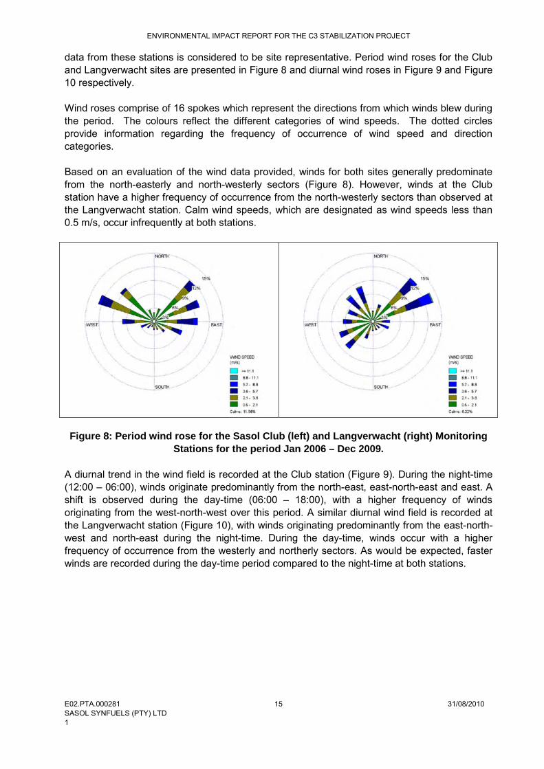
data from these stations is considered to be site representative. Period wind roses for the Club and Langverwacht sites are presented in Figure 8 and diurnal wind roses in Figure 9 and Figure 10 respectively.
Wind roses comprise of 16 spokes which represent the directions from which winds blew during the period. The colours reflect the different categories of wind speeds. The dotted circles provide information regarding the frequency of occurrence of wind speed and direction categories.
Based on an evaluation of the wind data provided, winds for both sites generally predominate from the north-easterly and north-westerly sectors (Figure 8). However, winds at the Club station have a higher frequency of occurrence from the north-westerly sectors than observed at the Langverwacht station. Calm wind speeds, which are designated as wind speeds less than 0.5 m/s, occur infrequently at both stations.
Figure 8: Period wind rose for the Sasol Club (left) and Langverwacht (right) Monitoring Stations for the period Jan 2006 – Dec 2009.
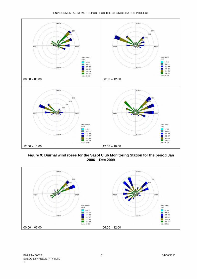
A diurnal trend in the wind field is recorded at the Club station (Figure 9). During the night-time (12:00 – 06:00), winds originate predominantly from the north-east, east-north-east and east. A shift is observed during the day-time (06:00 – 18:00), with a higher frequency of winds originating from the west-north-west over this period. A similar diurnal wind field is recorded at the Langverwacht station (Figure 10), with winds originating predominantly from the east-north-west and north-east during the night-time. During the day-time, winds occur with a higher frequency of occurrence from the westerly and northerly sectors. As would be expected, faster winds are recorded during the day-time period compared to the night-time at both stations.
ENVIRONMENTAL IMPACT REPORT FOR THE C3 STABILIZATION PROJECT
E02.PTA.000281 31/08/2010SASOL SYNFUELS (PTY) LTD1
16
00:00 – 06:00 06:00 – 12:00
12:00 – 18:00 12:00 – 18:00
Figure 9: Diurnal wind roses for the Sasol Club Monitoring Station for the period Jan 2006 – Dec 2009
00:00 – 06:00 06:00 – 12:00

ENVIRONMENTAL IMPACT REPORT FOR THE C3 STABILIZATION PROJECT
E02.PTA.000281 31/08/2010SASOL SYNFUELS (PTY) LTD1
17
12:00 – 18:00 12:00 – 18:00
Figure 10: Diurnal wind roses for the Langverwacht Monitoring Station for the period Jan 2006 – Dec 2009
4.5.1 Atmospheric Stability
Atmospheric stability is commonly categorised into six stability classes. These are briefly described in Table 3. The atmospheric boundary layer is usually unstable during the day due to turbulence caused by the sun's heating effect on the earth's surface. The depth of this mixing layer depends mainly on the amount of solar radiation, increasing in size gradually from sunrise to reach a maximum at about 5-6 hours after sunrise. The degree of thermal turbulence is increased on clear warm days with light winds. During the night-time a stable layer, with limited vertical mixing, exists. During windy and/or cloudy conditions, the atmosphere is normally neutral).
Table 3: Atmospheric Stability Classes
A Very unstable calm wind, clear skies, hot daytime conditions
B Moderately unstable clear skies, daytime conditions
C Unstable moderate wind, slightly overcast daytime conditions
D Neutral high winds or cloudy days and nights
E Stable moderate wind, slightly overcast night-time conditions
F Very stable low winds, clear skies, cold night-time conditions

ENVIRONMENTAL IMPACT REPORT FOR THE C3 STABILIZATION PROJECT
E02.PTA.000281 31/08/2010SASOL SYNFUELS (PTY) LTD1
18
Figure 11: Stability class frequency distribution for Sasol Club (top) and Langverwacht (bottom) Monitoring Stations
Due to the high frequency of very stable atmospheric conditions (Category F), it is likely that an inversion layer will develop, particularly in the early hours of winter mornings. This phenomenonhas the possibility of increasing ground level pollution concentrations.
4.5.2 Precipitation
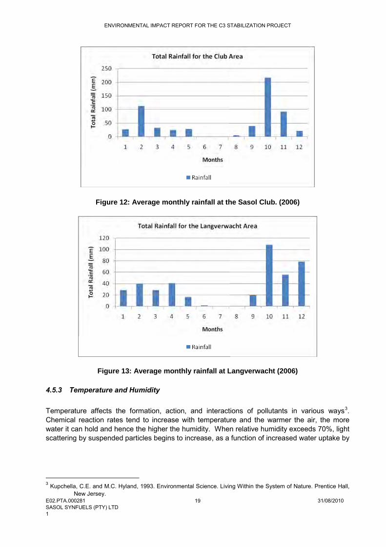
Precipitation cleanses the air by washing out particles suspended in the atmosphere1. It is calculated that precipitation accounts for about 80-90% of the mass of particles removed from the atmosphere2
Figure 12. Total monthly rainfall figures for the Sasol Club and Langverwacht are
depicted in and Figure 13 respectively. The area under investigation lies in the summer rainfall region of South Africa, receiving a total annual rainfall of 418 mm for the Club site during 2006 and 603.6 mm for the Langverwacht site during the same period. 1 Kupchella, C.E. and M.C. Hyland, 1993. Environmental Science. Living Within the System of Nature. Prentice Hall,
New Jersey.2 CEPA/FPAC Working Group, 1999. National Ambient Air Quality Objectives for Particulate Matter. Part 1: Science
Assessment Document. Minister, Public Works and Government Services, Ontario. Available at URL: http://www.hc-sc.gc.ca/bch.
ENVIRONMENTAL IMPACT REPORT FOR THE C3 STABILIZATION PROJECT
E02.PTA.000281 31/08/2010SASOL SYNFUELS (PTY) LTD1
19
Figure 12: Average monthly rainfall at the Sasol Club. (2006)
Figure 13: Average monthly rainfall at Langverwacht (2006)
4.5.3 Temperature and Humidity
Temperature affects the formation, action, and interactions of pollutants in various ways3
3 Kupchella, C.E. and M.C. Hyland, 1993. Environmental Science. Living Within the System of Nature. Prentice Hall,
New Jersey.
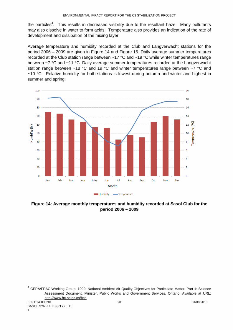
.Chemical reaction rates tend to increase with temperature and the warmer the air, the more water it can hold and hence the higher the humidity. When relative humidity exceeds 70%, light scattering by suspended particles begins to increase, as a function of increased water uptake by
ENVIRONMENTAL IMPACT REPORT FOR THE C3 STABILIZATION PROJECT
E02.PTA.000281 31/08/2010 SASOL SYNFUELS (PTY) LTD 1
20
the particles4
. This results in decreased visibility due to the resultant haze. Many pollutants may also dissolve in water to form acids. Temperature also provides an indication of the rate of development and dissipation of the mixing layer.
Average temperature and humidity recorded at the Club and Langverwacht stations for the period 2006 – 2009 are given in Figure 14 and Figure 15. Daily average summer temperatures recorded at the Club station range between ~17 °C and ~19 °C while winter temperatures range between ~7 °C and ~11 °C. Daily average summer temperatures recorded at the Langverwacht station range between ~18 °C and 19 °C and winter temperatures range between ~7 °C and ~10 °C. Relative humidity for both stations is lowest during autumn and winter and highest in summer and spring.
Figure 14: Average monthly temperatures and humidity recorded at Sasol Club for the
period 2006 – 2009
4 CEPA/FPAC Working Group, 1999. National Ambient Air Quality Objectives for Particulate Matter. Part 1: Science
Assessment Document. Minister, Public Works and Government Services, Ontario. Available at URL: http://www.hc-sc.gc.ca/bch.

ENVIRONMENTAL IMPACT REPORT FOR THE C3 STABILIZATION PROJECT
E02.PTA.000281 31/08/2010 SASOL SYNFUELS (PTY) LTD 1
21
Figure 15: Average monthly temperatures and humidity recorded at Sasol Langverwacht
for the period 2006 – 2009 4.6 Biodiversity (Fauna and Flora) Site alternative Site Description
Condensate #3 buffer tank
Preferred site alternative: The preferred site alternative for the placement of the Condensate #3 buffer tank is at the SCC plant (S 26°33’16.1’’; E 29°09’39.3’’) as it reduces the need for additional pipelines.
The site is completely transformed and is characterised by numerous chemical and process plants, pipelines, cooling towers, flares, stacks, roads and other associated infrastructure. The site occurs in the primary area of the Sasol Synfuels complex and access is strictly controlled.
Alternative 2: The second site alternative for the Condensate #3 plant is in the HP tank farm (S 26°32’55.0’’; E 29°10’08.3’’).
The site is completely transformed. No fauna and flora of conservation value is found on the site. The site occurs in the primary area of the Sasol Synfuels complex and access is strictly controlled.
Propylene Store Preferred Site Alternative: The preferred site alternative for the propylene sphere is west of the PP2 plant (S 26°33’10.0’’; E 29°11’01.1’’).
This site was previously used as a lay-down area for contractors and is covered by a 10 – 100 cm ash layer and doleritic material. The site can be regarded as completely disturbed. This site occurs in

ENVIRONMENTAL IMPACT REPORT FOR THE C3 STABILIZATION PROJECT
E02.PTA.000281 31/08/2010 SASOL SYNFUELS (PTY) LTD 1
22
Site alternative Site Description the secondary area of the Sasol complex.
4.7 Air Quality On 23 November 2007 the Highveld was declared a priority area, referred to as the Highveld Priority Area, in terms of section 18(1) of the National Environmental Management: Air Quality Act, 2004 (Act No 39 of 2004). This implies that the ambient air quality within the Highveld Priority Area exceeds or may exceed ambient air quality standards, alternatively, that a situation exists within the Highveld Priority Area, which is causing or may cause a significant negative impact on air quality in the area, and that the area requires specific air quality management action to rectify the situation. The area declared as such, includes inter alia the local municipalities of Govan Mbeki, Dipaleseng, Lekwa, Msukaligwa, and Pixley ka Seme. Hence, five of the seven local municipalities constituting the District form part of the Highveld Priority Area. 4.7.1 Identified Sensitive Receptors A sensitive receptor for the purposes of the current investigation can be defined as a person or place where involuntary exposure to pollutants released by the pipeline could take place. The following receptors have been identified from 1:50 000 maps and satellite images of the area. Table 4: Identified Sensitive Receptors in the Study Area
Receptor Distance (km) Direction from Source
Secunda ~5 NNE Embalenhle ~4 NW Trichardt ~10 NE Brendan Village ~15 NW Springbokdraai ~13 W Rietkuil ~10 SW
4.8 Noise The Sasol Synfuels Complex is a source of existing noise as a result of current industrial processes that are taking place. The noise at the Complex is within 85 dBA.
4.9 Social The proposed project falls within the Govan Mbeki Local Municipality (GMLM) which is located in the north west of the Gert Sibande District Municipality (GSDM). The GMLM has the most diversified economy within the GSDM, dominated by the petrochemical industry (Sasol II and III
ENVIRONMENTAL IMPACT REPORT FOR THE C3 STABILIZATION PROJECT
E02.PTA.000281 31/08/2010 SASOL SYNFUELS (PTY) LTD 1
23
complexes) and coal and gold mining. Secunda and eMbalenhle are the closest town/communities to the study area. The study area extends potentially across much of the Govan Mbeki Municipality, which consists of Secunda, eMbalenhle, Kinross, Evander, Trichardt, Charl Cilliers, Leslie/Leandra, Lebohang, Eendracht, Bethal and eMzinoni. The Govan Mbeki Local Municipality has the largest number (53.8% or 99201 people)5
and highest level of employment within the District. This could be attributed to the fact that the GMLM is one of two local municipalities that hosts the majority of all the mining, manufacturing and agricultural activity taking place within the District.
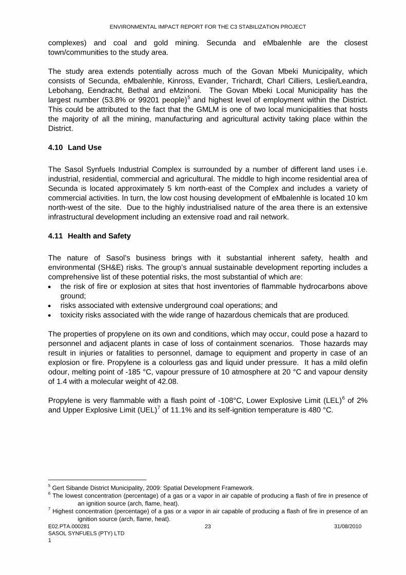
4.10 Land Use The Sasol Synfuels Industrial Complex is surrounded by a number of different land uses i.e. industrial, residential, commercial and agricultural. The middle to high income residential area of Secunda is located approximately 5 km north-east of the Complex and includes a variety of commercial activities. In turn, the low cost housing development of eMbalenhle is located 10 km north-west of the site. Due to the highly industrialised nature of the area there is an extensive infrastructural development including an extensive road and rail network. 4.11 Health and Safety The nature of Sasol’s business brings with it substantial inherent safety, health and environmental (SH&E) risks. The group’s annual sustainable development reporting includes a comprehensive list of these potential risks, the most substantial of which are: • the risk of fire or explosion at sites that host inventories of flammable hydrocarbons above
ground; • risks associated with extensive underground coal operations; and • toxicity risks associated with the wide range of hazardous chemicals that are produced. The properties of propylene on its own and conditions, which may occur, could pose a hazard to personnel and adjacent plants in case of loss of containment scenarios. Those hazards may result in injuries or fatalities to personnel, damage to equipment and property in case of an explosion or fire. Propylene is a colourless gas and liquid under pressure. It has a mild olefin odour, melting point of -185 °C, vapour pressure of 10 atmosphere at 20 °C and vapour density of 1.4 with a molecular weight of 42.08. Propylene is very flammable with a flash point of -108°C, Lower Explosive Limit (LEL)6 of 2% and Upper Explosive Limit (UEL)7
of 11.1% and its self-ignition temperature is 480 °C.
5 Gert Sibande District Municipality, 2009: Spatial Development Framework. 6 The lowest concentration (percentage) of a gas or a vapor in air capable of producing a flash of fire in presence of
an ignition source (arch, flame, heat). 7 Highest concentration (percentage) of a gas or a vapor in air capable of producing a flash of fire in presence of an
ignition source (arch, flame, heat).

ENVIRONMENTAL IMPACT REPORT FOR THE C3 STABILIZATION PROJECT
E02.PTA.000281 31/08/2010 SASOL SYNFUELS (PTY) LTD 1
24
4.12 Heritage The Sasol Synfuels Complex is a highly developed Industrial area that has been in operation for more than 50 years, the landscape has been changed by the development. None of the structures have aesthetic, historic, research or historical significance. There are no sites of archaeological or cultural significance known on the proposed study area. Sasol will ensure that all requirements of Chapter II, Section 38 of the National Heritage Resources Act, Act 25 of 1999, are complied with in the Scoping process and that the comments and/or recommendations of the relevant heritage resources authority responsible for the area in which the development is proposed, are considered.
ENVIRONMENTAL IMPACT REPORT FOR THE C3 STABILIZATION PROJECT
E02.PTA.000281 31/08/2010 SASOL SYNFUELS (PTY) LTD 1
25
5 ENVIRONMENTAL IMPACT ASSESSMENT METHODOLOGY AND APPROACH 5.1 Approach to Undertaking the Study An Environmental Impact Assessment for the proposed C3 Stabilization Project has been undertaken in accordance with the Environmental Impact Assessment (EIA) Regulations published in Government Notice No R. 385, R. 386 and R. 387 of 2006 in terms of Section 24 (5) of the National Environmental Management Act (Act No 107 of 1998, ‘NEMA’). The environmental studies are following a two-phased approach: • Phase 1: Environmental Scoping Study (ESS) – complete. • Phase 2: Environmental Impact Assessment (EIA) – this report, including an Environmental
Management Plan (EMP) to address impacts identified during the ESS and EIA. 5.2 Environmental Scoping Study An issues-based ESS was first undertaken for the proposed project. Existing information and input from the Authorities as well as Interested and Affected Parties (I&APs) were used to identify and evaluate potential environmental impacts (both social and biophysical) associated with the proposed project. No fatal flaws associated with the proposed project were identified through the ESS, although potentially significant environmental impacts were identified as requiring further in-depth study within the EIA. The Scoping Phase of the environmental studies provided I&APs with the opportunity to receive information regarding the proposed project, participate in the EIA process and raise issues of concern. The draft Environmental Scoping Report (ESR) was made available at public places for I&AP review and comment from 13 May 2010 to 14 June 2010. All the comments, concerns and suggestions received during the public participation process for the Scoping Phase and from the draft report review period were included in the Final Scoping Report, which was submitted to the Mpumalanga Department of Economic Development, Environment and Tourism (MDEDET) for review and decision-making. 5.3 Authority Consultation 5.3.1 Consultation with Decision-Making Authority The relevant authority (MDEDET) providing input into the proposed project has been consulted from the outset of this study, and will continue to be engaged throughout the project process. The consultation process to date with MDEDET aimed to determine specific authority requirements with regards to the proposed project, and ensure inclusion of these in the environmental studies. Authority consultation to date also included the following activities: • Submission of an application for authorisation in terms of Regulations R385 to R387 of the
National Environmental Management Act (NEMA No 107 of 1998) to the MDEDET; • Approval of the application documentation by MDEDET was received on 19 March 2010 and
the reference number, 17/2/2/1(j) GS01 was assigned to the project; • Site visit with Mr Martin Fuwela (MDEDET) on 13 April 2010 and • Acceptance of the final Environmental Scoping Report and Plan of Study for EIA on 29 July
2010 (refer to Appendix A).

ENVIRONMENTAL IMPACT REPORT FOR THE C3 STABILIZATION PROJECT
E02.PTA.000281 31/08/2010 SASOL SYNFUELS (PTY) LTD 1
26
5.4 Environmental Impact Assessment As part of the overall project planning process, this EIA aims to achieve the following: • to supplement, where necessary, the assessment of the social and biophysical
environments affected by the proposed project during the Scoping study; • to assess impacts on the study area in terms of environmental criteria; • to identify and recommend appropriate mitigation measures for potentially significant
environmental impacts; • to complete an Environmental Management Plan (EMP) for the inclusion of proposed
mitigation measures; and • to undertake a fully inclusive public participation process to ensure that I&AP issues and
concerns are recorded and addressed. 5.4.1 Methodology – Assessment of Impacts Impact assessment must take account of the nature, scale and duration of effects on the environment, whether such effects are positive (beneficial) or negative (detrimental). Each issue/impact is also assessed according to the project stages from planning, through construction and operation to the decommissioning phase. Where necessary, the proposal for mitigation or optimisation of an impact is noted. A brief discussion of the impact and the rationale behind the assessment of its significance is included below. 5.4.2 Impact Assessment Methodology The potential environmental impacts of the C3 Stabilization Project will be evaluated according to nature, extent, duration, intensity, probability and significance of the impacts, whereby: • Nature: A brief written statement of the environmental aspect being impacted upon by a
particular action or activity. • Extent: The area over which the impact will be expressed. Typically, the severity and
significance of an impact have different scales and as such bracketing ranges are often required. This is often useful during the detailed assessment phase of a project in terms of further defining the determined significance or intensity of an impact. For example, high at a local scale, but low at a regional scale;
• Duration: Indicates what the lifetime of the impact will be; • Intensity: Describes whether an impact is destructive or benign; and • Probability: Describes the likelihood of an impact actually occurring. • Cumulative: In relation to an activity, means the impact of an activity that in itself may not
be significant but may become significant when added to the existing and potential impacts eventuating from similar or diverse activities or undertakings in the area.

ENVIRONMENTAL IMPACT REPORT FOR THE C3 STABILIZATION PROJECT
E02.PTA.000281 31/08/2010 SASOL SYNFUELS (PTY) LTD 1
27
Table 5: Criteria used for the rating of impacts
CRITERIA DESCRIPTION
EXTENT National
The whole of South Africa Regional
Provincial and parts of neighbouring provinces
Local Within a radius of 2km of the
construction site
Site Within the construction site
DURATION
Permanent Mitigation either by man or
natural process will not occur in such a way or in such a time span that the impact can be
considered transient
Long-term The impact will continue or last for the entire operational life of
the development, but will be mitigated by direct human action
or by natural processes thereafter. The only class of
impact which will be non-transitory
Medium-term The impact will last for the period of the construction
phase, where after it will be entirely negated
Short-term The impact will either disappear
with mitigation or will be mitigated through natural
process in a span shorter than the construction phase
INTENSITY
Very High Natural, cultural and social
functions and processes are altered to extent that they
permanently cease
High Natural, cultural and social
functions and processes are altered to extent that they
temporarily cease
Medium Affected environment is altered, but natural, cultural and social
functions and processes continue albeit in a modified way
Low Impact affects the environment
in such a way that natural, cultural and social functions and
processes are not affected
PROBABILTY OF
OCCURANCE
Definite Impact will certainly occur
Highly Probable Most likely that the impact will
occur
Probable The impact may occur
Improbable Likelihood of the impact materialising is very low

ENVIRONMENTAL IMPACT REPORT FOR THE C3 STABILIZATION PROJECT
E02.PTA.000281 31/08/2010 SASOL SYNFUELS (PTY) LTD 1
28
Significance is determined through a synthesis of impact characteristics. Significance is an indication of the importance of the impact in terms of both physical extent and time scale, and therefore indicates the level of mitigation required. The total number of points scored for each impact indicates the level of significance of the impact. Table 6: Criteria for the rating of classified impacts Very Low impact (1 point)
Impact is negligible.
Low impact (2 points)
A low impact has no permanent impact of significance. Mitigation measures are feasible and are readily instituted as part of a standing design, construction or operating procedure.
Medium impact (3 points)
Mitigation is possible with additional design and construction inputs.
High impact (4 points)
The design of the site may be affected. Mitigation and possible remediation are needed during the construction and/or operational phases. The effects of the impact may affect the broader environment.
Very high impact (5 points)
Permanent and important impacts. The design of the site may be affected. Intensive remediation is needed during construction and/or operational phases. Any activity which results in a “very high impact” is likely to be a fatal flaw.
Status Denotes the perceived effect of the impact on the affected area. Positive (+) Beneficial impact. Negative (-) Deleterious or adverse impact. Neutral (/) Impact is neither beneficial nor adverse. It is important to note that the status of an impact is assigned based on the status quo – i.e. should the project not proceed. Therefore not all negative impacts are equally significant. The suitability and feasibility of all proposed mitigation measures will be included in the assessment of significant impacts. This will be achieved through the comparison of the significance of the impact before and after the proposed mitigation measure is implemented. Mitigation measures identified as necessary will be included in an EMP. 5.5 EIA Report - EIR This EIR will contain the following: • Details of the EAP who complied the report and their expertise to carry out an EIA; • Detailed description of the proposed project; • Description of property on which the activity is to be undertaken; • A description of the environment that might be affected by the activity and the manner in
which the physical, biological, social, economic and cultural aspects of the environment may be affected by the proposed activity;
• Details of the public participation process conducted during the Scoping Phase and the ongoing consultation during the EIA phase;
• Description of the need and desirability of the proposed activity and identified potential alternatives to the proposed activity, including advantages and disadvantages that the

ENVIRONMENTAL IMPACT REPORT FOR THE C3 STABILIZATION PROJECT
E02.PTA.000281 31/08/2010 SASOL SYNFUELS (PTY) LTD 1
29
proposed activity or alternatives may have on the environment and the community that may be affected by the activity;
• An indication of the methodology used in determining the significance of potential environmental impacts;
• A description and comparative assessment of all alternatives identified during the environmental impact assessment process;
• A summary of the findings and recommendations of any specialist report or report on a specialised process;
• A description of all environmental issues that were identified during the environmental impact assessment process, an assessment of the significance of each issue and an indication of the extent to which the issue could be addressed by the adoption of mitigation measures;
• An assessment of each identified potentially significant impact, including cumulative impacts, the nature of the impact, the extent and duration of the impact, the probability of the impact occurring, the degree to which the impact can be reversed, the degree to which the impact may cause irreplaceable loss of resources and the degree to which the impact can be mitigated;
• A description of any assumptions, uncertainties and gaps in knowledge; • An opinion as to whether the activity should or should not be authorised, and if the opinion is
that it should be authorised, any conditions that should be made in respect of that authorisation;
• An environmental impact statement which contains a summary of the key findings of the environmental impact assessment; and a comparative assessment of the positive and negative implications of the proposed activity and identified alternatives;
• A draft environmental management plan and • Copies of any specialist reports and reports on specialised processes. 5.6 Draft Environmental Management Plan During the compilation of the EIA, a draft EMP will be compiled in accordance with the NEMA regulations. The draft EMP will provide the actions for the management of identified environmental impacts emanating from the proposed project and a detailed outline of the implementation programme to minimise and/or eliminate the anticipated negative environmental impacts. The draft EMP will provide strategies to be used to address the roles and responsibilities of environmental management personnel on site, and a framework for environmental compliance and monitoring. The EMP will include the following: • Details of the person who prepared the EMP and the expertise of the person to prepare an
EMP; • Information on any proposed management or mitigation measures that will be taken to
address the environmental impacts that have been identified in the EIA Report, including environmental impacts or objectives in respect of planning and design, pre-construction and construction activities, operation or undertaking of the activities, rehabilitation of the environment and closure where relevant;
• A detailed description of the aspects of the activity that are covered by the draft EMP; • An identification of the persons who will be responsible for the implementation of the
measures;

ENVIRONMENTAL IMPACT REPORT FOR THE C3 STABILIZATION PROJECT
E02.PTA.000281 31/08/2010 SASOL SYNFUELS (PTY) LTD 1
30
• Where appropriate, time periods within which the measures contemplated in the draft EMP must be implemented; and
• Proposed mechanisms for monitoring compliance with the EMP and reporting thereon. 5.7 Assumptions and Limitations • All information provided by Sasol to the EIA consultant was correct and valid at the time it
was provided. • The EIA consultants do not accept any responsibility in the event that additional information
comes to light at a later stage of the process. • All data from unpublished research is valid and accurate. • Air Quality –
− For input into the Tanks model, the pressure bullets were assumed to be aluminium, unheated and were modelled as fixed roof tanks.
− The cumulative impacts due to emissions from the current plant operations and surrounding sources was not included in this assessment. A detailed emissions inventory of all emissions sources at the Sasol Plant and surrounding areas would need to be compiled for this purpose. Given the complexity of such a study and the limited availability of this information, only sources for which information was provided were evaluated.
• Consequence analysis – this study is not a detailed risk assessment study, therefore no quantitative analysis was performed on the probability of such events occurring.
• The scope of this investigation is limited to assessing the potential environmental impacts associated with the C3 Stabilization project and not other projects identified as part of the expansion programme.

ENVIRONMENTAL IMPACT REPORT FOR THE C3 STABILIZATION PROJECT
E02.PTA.000281 31/08/2010 SASOL SYNFUELS (PTY) LTD 1
31
6 PUBLIC PARTICIPATION PROCESS 6.1 Overview of the Public Participation Process The public participation process undertaken to date is discussed below. Some of the main aims of the public participation process are to serve as a structure for communication and consultation with I&APs and to assist I&APs in identifying issues of concern and suggestions for enhanced benefits of the project and to comment on the findings of the EIA process. To this end, the primary aims of the public participation process are: • to inform interested and affected parties (I&APs) and key stakeholders of the proposed
project; • to initiate meaningful and timeous participation of I&APs; • to identify issues and concerns of key stakeholders and I&APs with regards to the proposed
development (i.e. focus on important issues); • to promote transparency and an understanding of the proposed project and its potential
environmental (social and biophysical) impacts; • to provide information used for decision-making; • to provide a structure for liaison and communication with I&APs and key stakeholders; • to assist in identifying potential environmental (social and biophysical) impacts associated
with the proposed development; • to ensure inclusiveness (the needs, interests and values of I&APs must be considered in the
decision-making process); • to focus on issues relevant to the project and issues considered important by I&APs and key
stakeholders; and • to provide responses to I&APs’ comments and queries. 6.1.1 Consultation with Relevant Authorities and Key Stakeholders Consultation with other relevant authorities and key stakeholders was undertaken through telephone calls and written correspondence in order to actively engage these authorities from the outset and to provide background information about the proposed project. The representatives from these authorities were requested to formally provide input into the EIA process. They include: • Department of Water Affairs; • Govan Mbeki Local Municipality; • Gert Sibande District Municipality; and • South African Heritage Resources Agency: Mpumalanga Region • NGO – groundWorks • Waterval Forum 6.1.2 Advertising In terms of the EIA Regulations, the commencement of the EIA phase of the project was advertised in the Echo and Ridge Times newspapers. The primary aim of these adverts was to ensure that the widest group of I&APs possible are informed of the project. Advertisements
ENVIRONMENTAL IMPACT REPORT FOR THE C3 STABILIZATION PROJECT
E02.PTA.000281 31/08/2010 SASOL SYNFUELS (PTY) LTD 1
32
about the availability of the EIR for public comment as well as details of the public meeting were also placed in the local press (refer to Appendix D). 6.1.3 Identification of and Consultation with Key Stakeholders I&APs and Key Stakeholders have been identified during the ESS phase of the project. The identification of I&APs and key stakeholders will continue in the EIA phase of the project as the public participation process is a continuous process that runs throughout the duration of an environmental investigation. 6.1.4 I&AP Database All I&AP information (including contact details), together with dates and details of consultations and a record of all issues raised is recorded within a comprehensive database of I&APs (refer to Appendix E). This database will be updated on an on-going basis throughout the project, and will act as a record of the communication/involvement process. 6.1.5 Consultation and Public Involvement Consultation with I&APs is considered to be critical to the success of any EIA process. Therefore, one-on-one consultation (via telephone calls, fax and emails) and a public meeting during the EIA phase will be undertaken. The aim of this process will be to provide I&APs with details regarding the process and to obtain further comments regarding the proposed project.
Minutes of all meetings held will be compiled and forwarded to all attendees. These minutes will also be included in the final EIR. 6.1.6 Issues Trail All issues, comments and concerns raised during the public participation process of the EIA study has been compiled into an Issues Trail (refer to Appendix E). 6.1.7 Public Review of the Draft Environmental Impact Report The draft EIR will be made available for public review for a 30 day review period from 06 September 2010 to 06 October 2010. Hard copies of the report were available for review at the following public places: • Secunda Municipality Library • Sasol Technology Library • Embalenhle Municipal Library • Offices of Bohlweki-SSI Environmental in Monument Park, Pretoria • Bohlweki-SSI Environmental website (www.bohlweki.co.za/library.php) In addition, the availability of the draft EIR for public review and comment were advertised in the Ridge Times and Echo newspapers (week ending 03 September 2010): A copy of this advert is attached in Appendix D. In addition, all registered I&APs on the database were notified of the availability of the report. All comments received from I&APs during the review period will be recorded and included within the final EIR.
ENVIRONMENTAL IMPACT REPORT FOR THE C3 STABILIZATION PROJECT
E02.PTA.000281 31/08/2010 SASOL SYNFUELS (PTY) LTD 1
33
6.1.8 Authority Review of the Environmental Impact Report After the public review period, all relevant comments received from the public will be considered and included into a final EIR. This final document will be submitted to MDEDET for final review and decision-making. 6.1.9 Environmental Authorisation On receipt of environmental authorisation (positive or negative) for the project, I&APs registered on the project database will be informed of this authorisation and its associated terms and conditions by correspondence.
ENVIRONMENTAL IMPACT REPORT FOR THE C3 STABILIZATION PROJECT
E02.PTA.000281 31/08/2010 SASOL SYNFUELS (PTY) LTD 1
34
7 CONSTRUCTION PHASE IMPACTS The proposed C3 Stabilization project is anticipated to impact on a range of biophysical and socio-economic aspects of the environment. One of the main purposes of the Environmental Impact Assessment (EIA) process is to understand these potential impacts and to determine if they can be minimised or mitigated. 7.1 Construction Phase Impacts These are impacts on the biophysical and socio-economic environment that would occur during the construction phase of the proposed project. They are inherently temporary in duration, but may have longer lasting effects. Construction phase impacts relating to the proposed project could potentially include: • Erosion due to site clearing; • Dust; • Impact on water quality • Impact on flora and fauna; • Impact on air quality • Noise pollution; • Waste pollution; • Health and safety; and • Social impacts.
The assessment of identified impacts during the construction phase is consolidated into Table 7 to Table 10. 7.1.1 Erosion during Site Clearing Potential erosion impacts are anticipated to be limited to the construction phase during site clearing activities. Where possible, clearing activities and earth scraping should preferably be restricted to the dry season in order to prevent erosion. The careful position of soil piles, and runoff control, during all phases of development will limit the extent of erosion on the site. These impacts are not considered to be significant as long as they are mitigated by the implementation of the Environmental Management Plan (EMP). 7.1.2 Dust Construction is commonly of a temporary nature with a definite beginning and end. Construction usually consists of a series of different operations, each with its own duration and potential for dust generation. Dust emission will vary from day to day depending on the phase of construction, the level of activity, and the prevailing meteorological conditions8
(USEPA, 1996).
8 US Environmental Protection Agency, 1996. Compilation of Air Pollution Emission Factors (AP-42), 6th Edition, Volume 1, as contained in the AirCHIEF CD-ROM, US Environmental Protection Agency, Research Triangle Park, North Carolina. Available at URL: http://www.epa.gov/ttn/chief/ap42/.
ENVIRONMENTAL IMPACT REPORT FOR THE C3 STABILIZATION PROJECT
E02.PTA.000281 31/08/2010 SASOL SYNFUELS (PTY) LTD 1
35
The following possible sources of fugitive dust have been identified as activities which could potentially generate dust during construction operations at the site: • Vehicle activities associated with the transport of equipment to the site; • Preparation of the surface areas which may be required prior to the set up of new
infrastructure; and • The removal of construction equipment from site after the set up of new equipment. Control techniques for fugitive dust sources during the construction phase include watering, chemical stabilization or reduction or surface wind speed with windbreaks or source enclosures. Watering is the most common and least expensive method although it only provides temporary dust control. Wet suppression of unpaved areas can achieve dust emission reductions of approximately 70% or more, which can be increased by up to 95% through the use of chemical stabilization. The use of chemicals provides for longer dust suppression but is more costly and may have adverse environmental effects. 7.1.3 Impacts on Water Resources (Ground and Surface Water) The potential impacts associated with surface water are anticipated to be low as existing stormwater management structures and sumps are designed to trap any potentially contaminated stormwater and return it to the relevant process or allow it to be stored and properly disposed off. As the site is already highly developed and industrialised, all precautionary steps must be taken to mitigate against spills or contamination of surface water and groundwater. Mitigation measures relating to water resource management are included in the EMP (Appendix H). 7.1.4 Impact on Fauna and Flora The site is completely transformed and of no conservation potential. The impact on biodiversity is therefore negligible during the construction phase. 7.1.5 Noise Pollution During the construction phase there is likely to be an increase in noise pollution. The following possible sources of noise could potentially generate noise pollution during construction: • Construction activities (blasting, excavating); • Construction vehicles; and • Construction staff. The potential noise impacts can be effectively mitigated through the implementation of the EMP (Appendix H). 7.1.6 Waste Pollution Waste generation during the construction phase will have a negative impact on the environment, if not controlled adequately. This impact can be effectively mitigated through the implementation of the EMP.

ENVIRONMENTAL IMPACT REPORT FOR THE C3 STABILIZATION PROJECT
E02.PTA.000281 31/08/2010 SASOL SYNFUELS (PTY) LTD 1
36
7.1.7 Health and Safety The potential impacts on health and safety of staff during construction are anticipated to be low, provided that mitigation measures are implemented. The carrying out of appropriate site inspections and audits during construction need to be conducted to ensure safety issues are carefully considered through the construction process. 7.1.8 Social Impacts It is anticipated that the construction phase could lead to an influx of construction workers (± 300) that could lead to a change in the number and composition of the local community, and impact on economy, health, safety and social well-being. This might place additional demands on municipal services, such as water, electricity, and sewerage and could impact on health and safety if such services are not available. It is possible that the majority of the construction workforce would be sourced from within the area due to the skills levels required. The specialised workforce would likely be sourced from outside the area and would most probably be housed within neighbouring towns or within Secunda.

ENVIRONMENTAL IMPACT REPORT FOR THE C3 STABILIZATION PROJECT
E02.PTA.000281 31/08/2010 SASOL SYNFUELS (PTY) LTD 1
37
Significance Rating Key: Very Low
Low Moderate
High (Negative Impact) High (Positive Impact) Very High (Fatal Flaw)
Table 7: Assessment of the Potential Impacts during the Construction Phase of the Condensate #3 tank at the SCC Plant (Preferred)
NATURE/IMPACT MITIGATION EXTENT STATUS DURATION PROBABILITY INTENSITY SIGNIFICANCE POINTS ALLOCATED
Erosion due to site clearing
Without Site Negative Medium-term Highly Probable
Medium Low 2
With Site Negative Medium-term Improbable Low Very Low 1
Dust Without Site Negative Medium-term Highly
probable Medium Low 2
With Site Negative Medium-term Probable Low Low 2 Impact on water
quality Without Local Negative Medium-term Improbable Low Low 2
With Local Negative Medium-term Improbable Low Low 2 Impact on fauna
and flora Without Site Neutral Medium-term Improbable Low Very Low 1
With Site Neutral Medium-term Improbable Low Very Low 1
Noise pollution Without Site Negative Medium-term Highly
probable Medium Low 2
With Site Negative Medium-term Probable Low Very Low 1
Waste pollution Without Site Negative Medium-term Highly
probable Low Low 2
With Site Negative Medium-term Improbable Low Very Low 1 Health and
Safety during construction
Without Site Negative Medium-term Probable Low Low 2 With Site Negative Medium-term Improbable Low Very Low 1

ENVIRONMENTAL IMPACT REPORT FOR THE C3 STABILIZATION PROJECT
E02.PTA.000281 31/08/2010 SASOL SYNFUELS (PTY) LTD 1
38
NATURE/IMPACT MITIGATION EXTENT STATUS DURATION PROBABILITY INTENSITY SIGNIFICANCE POINTS ALLOCATED
Social Impacts Without Regional Negative Medium-term Highly
Probable Medium Medium 3
With Regional Negative Medium-term Probable Low Low 2 Table 8: Assessment of the Potential Impacts during the Construction Phase of the Condensate #3 tank at the HP Tank Farm
NATURE/IMPACT MITIGATION EXTENT STATUS DURATION PROBABILITY INTENSITY SIGNIFICANCE POINTS ALLOCATED
Erosion due to site clearing
Without Site Negative Medium-term Probable Low Low 2 With Site Negative Medium -term Improbable Low Very Low 1
Dust Without Site Negative Medium -term Probable Medium Low 2
With Site Negative Medium -term Probable Low Low 2 Impact on water
quality Without Local Negative Medium -term Improbable Low Low 2
With Local Negative Medium -term Improbable Low Low 2 Impact on fauna
and flora Without Site Neutral Medium -term Improbable Low Very Low 1
With Site Neutral Medium -term Improbable Low Very Low 1
Noise pollution Without Site Negative Medium -term Highly
probable Medium Low 2
With Site Negative Medium -term Probable Low Very Low 1
Waste pollution Without Site Negative Medium -term Highly
probable Low Low 2
With Site Negative Medium-term Improbable Low Very Low 1 Health and
Safety during construction
Without Site Negative Medium -term Probable Low Low 2 With Site Negative Medium -term Improbable Low Very Low 1
Social Impacts Without Regional Negative Medium -term Highly
Probable Medium Medium 3
With Regional Negative Medium -term Probable Low Low 2

ENVIRONMENTAL IMPACT REPORT FOR THE C3 STABILIZATION PROJECT
E02.PTA.000281 31/08/2010 SASOL SYNFUELS (PTY) LTD 1
39
Table 9: Average points allocated to the different site alternatives for the buffer tank
PHASE ALTERNATIVES TOTAL (POINTS ALLOCATED)9
Without Mitigation With Mitigation
Construction Condensate #3 tank at the SCC Plant (Preferred) 16 11 Condensate #3 tank at the HP Tank Farm 16 11
Table 10: Assessment of the Potential Impacts during the Construction Phase of the Propylene Storage Facility west of PP2 plant
NATURE/IMPACT MITIGATION EXTENT STATUS DURATION PROBABILITY INTENSITY SIGNIFICANCE Erosion due to site
clearing Without Site Negative Medium -term Highly Probable Low Low
With Site Negative Medium -term Improbable Low Very Low
Dust Without Site Negative Medium-term Highly probable Medium Low
With Site Negative Medium -term Probable Low Low Impact on water
quality Without Local Negative Medium -term Improbable Low Low
With Local Negative Medium -term Improbable Low Low Impact on fauna
and flora Without Site Neutral Medium -term Improbable Low Very Low
With Site Neutral Medium -term Improbable Low Very Low
Noise pollution Without Site Negative Medium -term Highly probable Medium Low
With Site Negative Medium -term Probable Low Very Low
Waste pollution Without Site Negative Medium -term Highly probable Low Low With Site Negative Medium -term Improbable Low Very Low
Health and Safety during construction
Without Site Negative Medium -term Probable Low Low With Site Negative Medium -term Improbable Low Very Low
Social Impacts Without Regional Negative Medium -term Highly Probable Medium Medium
With Regional Negative Medium -term Probable Low Low
9 During the impact assessment both alternatives ranked the same in terms of environmental criteria. However, from a technical point of view, the installation of the buffer tank in the HP tank farm is not preferred.
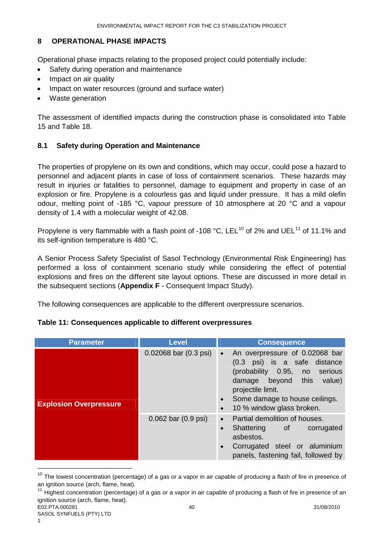
ENVIRONMENTAL IMPACT REPORT FOR THE C3 STABILIZATION PROJECT
E02.PTA.000281 31/08/2010 SASOL SYNFUELS (PTY) LTD 1
40
8 OPERATIONAL PHASE IMPACTS Operational phase impacts relating to the proposed project could potentially include: • Safety during operation and maintenance • Impact on air quality • Impact on water resources (ground and surface water) • Waste generation The assessment of identified impacts during the construction phase is consolidated into Table 15 and Table 18. 8.1 Safety during Operation and Maintenance The properties of propylene on its own and conditions, which may occur, could pose a hazard to personnel and adjacent plants in case of loss of containment scenarios. These hazards may result in injuries or fatalities to personnel, damage to equipment and property in case of an explosion or fire. Propylene is a colourless gas and liquid under pressure. It has a mild olefin odour, melting point of -185 °C, vapour pressure of 10 atmosphere at 20 °C and a vapour density of 1.4 with a molecular weight of 42.08. Propylene is very flammable with a flash point of -108 °C, LEL10 of 2% and UEL11
of 11.1% and its self-ignition temperature is 480 °C.
A Senior Process Safety Specialist of Sasol Technology (Environmental Risk Engineering) has performed a loss of containment scenario study while considering the effect of potential explosions and fires on the different site layout options. These are discussed in more detail in the subsequent sections (Appendix F - Consequent Impact Study). The following consequences are applicable to the different overpressure scenarios. Table 11: Consequences applicable to different overpressures
Parameter Level Consequence
Explosion Overpressure
0.02068 bar (0.3 psi) • An overpressure of 0.02068 bar (0.3 psi) is a safe distance (probability 0.95, no serious damage beyond this value) projectile limit.
• Some damage to house ceilings. • 10 % window glass broken.
0.062 bar (0.9 psi) • Partial demolition of houses. • Shattering of corrugated
asbestos. • Corrugated steel or aluminium
panels, fastening fail, followed by
10 The lowest concentration (percentage) of a gas or a vapor in air capable of producing a flash of fire in presence of an ignition source (arch, flame, heat). 11 Highest concentration (percentage) of a gas or a vapor in air capable of producing a flash of fire in presence of an ignition source (arch, flame, heat).
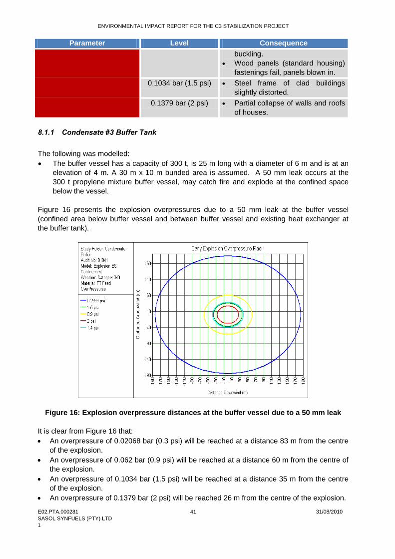
ENVIRONMENTAL IMPACT REPORT FOR THE C3 STABILIZATION PROJECT
E02.PTA.000281 31/08/2010 SASOL SYNFUELS (PTY) LTD 1
41
Parameter Level Consequence buckling.
• Wood panels (standard housing) fastenings fail, panels blown in.
0.1034 bar (1.5 psi) • Steel frame of clad buildings slightly distorted.
0.1379 bar (2 psi) • Partial collapse of walls and roofs of houses.
8.1.1 Condensate #3 Buffer Tank The following was modelled: • The buffer vessel has a capacity of 300 t, is 25 m long with a diameter of 6 m and is at an
elevation of 4 m. A 30 m x 10 m bunded area is assumed. A 50 mm leak occurs at the 300 t propylene mixture buffer vessel, may catch fire and explode at the confined space below the vessel.
Figure 16 presents the explosion overpressures due to a 50 mm leak at the buffer vessel (confined area below buffer vessel and between buffer vessel and existing heat exchanger at the buffer tank).
Figure 16: Explosion overpressure distances at the buffer vessel due to a 50 mm leak It is clear from Figure 16 that: • An overpressure of 0.02068 bar (0.3 psi) will be reached at a distance 83 m from the centre
of the explosion. • An overpressure of 0.062 bar (0.9 psi) will be reached at a distance 60 m from the centre of
the explosion. • An overpressure of 0.1034 bar (1.5 psi) will be reached at a distance 35 m from the centre
of the explosion. • An overpressure of 0.1379 bar (2 psi) will be reached 26 m from the centre of the explosion.

ENVIRONMENTAL IMPACT REPORT FOR THE C3 STABILIZATION PROJECT
E02.PTA.000281 31/08/2010 SASOL SYNFUELS (PTY) LTD 1
42
8.1.2 Propylene Storage Vessels The following scenario has been modelled: • A propylene storage vessel has a capacity of 1400 m3, is 52 m long with a diameter of 6 m
and is at an elevation of 6 m. A 52 m x 50 m bunded area is assumed. A 50 mm leak occurs at the 1400 m3 propylene storage vessel, may catch fire and explode in the confined space below the vessel.
It is believed that and explosion may occur in the confined space between two vessels or the confined space generated by all 5 vessels if the distance between the vessels is 5 m and less. To get smaller confined spaces that could be filled with vapour and that may result in an explosion it is necessary to separate the vessels more than 5 m. Figure 17 and Figure 18 present explosion overpressures due to a 50 mm leak at the storage vessel at the confined space between two vessels and between 5 vessels respectively.
Figure 17: Explosion overpressure distances due to a 50 mm leak at a confined space between two vessels
It is clear from Figure 17 that: • An overpressure of 0.02068 bar (0.3 psi) will be reached at a distance 333 m from the
centre of the explosion. • An overpressure of 0.062 bar (0.9 psi) will be reached at a distance 110 m from the centre
of the explosion. • An overpressure of 0.1034 bar (1.5 psi) will be reached at a distance 65 m from the centre
of the explosion. • An overpressure of 0.1379 bar (2 psi) will result in partial collapse of walls and roofs of
houses and will be reached 50 m from the centre of the explosion.
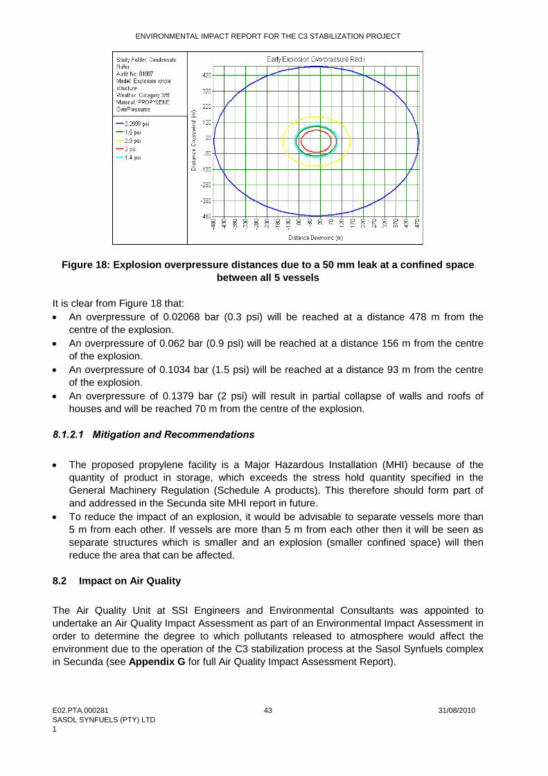
ENVIRONMENTAL IMPACT REPORT FOR THE C3 STABILIZATION PROJECT
E02.PTA.000281 31/08/2010 SASOL SYNFUELS (PTY) LTD 1
43
Figure 18: Explosion overpressure distances due to a 50 mm leak at a confined space between all 5 vessels
It is clear from Figure 18 that: • An overpressure of 0.02068 bar (0.3 psi) will be reached at a distance 478 m from the
centre of the explosion. • An overpressure of 0.062 bar (0.9 psi) will be reached at a distance 156 m from the centre
of the explosion. • An overpressure of 0.1034 bar (1.5 psi) will be reached at a distance 93 m from the centre
of the explosion. • An overpressure of 0.1379 bar (2 psi) will result in partial collapse of walls and roofs of
houses and will be reached 70 m from the centre of the explosion. 8.1.2.1 Mitigation and Recommendations • The proposed propylene facility is a Major Hazardous Installation (MHI) because of the
quantity of product in storage, which exceeds the stress hold quantity specified in the General Machinery Regulation (Schedule A products). This therefore should form part of and addressed in the Secunda site MHI report in future.
• To reduce the impact of an explosion, it would be advisable to separate vessels more than 5 m from each other. If vessels are more than 5 m from each other then it will be seen as separate structures which is smaller and an explosion (smaller confined space) will then reduce the area that can be affected.
8.2 Impact on Air Quality The Air Quality Unit at SSI Engineers and Environmental Consultants was appointed to undertake an Air Quality Impact Assessment as part of an Environmental Impact Assessment in order to determine the degree to which pollutants released to atmosphere would affect the environment due to the operation of the C3 stabilization process at the Sasol Synfuels complex in Secunda (see Appendix G for full Air Quality Impact Assessment Report).
ENVIRONMENTAL IMPACT REPORT FOR THE C3 STABILIZATION PROJECT
E02.PTA.000281 31/08/2010 SASOL SYNFUELS (PTY) LTD 1
44
The potential impact of emissions from the proposed project on the surrounding environment has been evaluated through the compilation of an emissions inventory for identified sources associated with the project and subsequent dispersion modelling simulations using the AERMOD dispersion model. Comparison with the South African ambient air quality standards has also been made to determine compliance in terms of the potential human for health impacts. 8.2.1 Model Overview AERMOD, a state-of-the-art Planetary Boundary Layer (PBL) air dispersion model, was developed by the American Meteorological Society and USEPA Regulatory Model Improvement Committee (AERMIC). AERMOD utilizes a similar input and output structure to ISCST312 and shares many of the same features, as well as offering additional features. AERMOD fully incorporates the PRIME13
building downwash algorithms, advanced depositional parameters, local terrain effects, and advanced meteorological turbulence calculations.
The AERMOD atmospheric dispersion modelling system is an integrated system that includes three modules: • A steady-state dispersion model designed for short-range (up to 50 km) dispersion of air
pollutant emissions from stationary industrial sources. • A meteorological data pre-processor (AERMET) for surface meteorological data, upper air
soundings, and optionally, data from on-site instrument towers. It then calculates atmospheric parameters needed by the dispersion model, such as atmospheric turbulence characteristics, mixing heights, friction velocity, Monin-Obukov length and surface heat flux.
• A terrain pre-processor (AERMAP) which provides a physical relationship between terrain features and the behaviour of air pollution plumes. It generates location and height data for each receptor location. It also provides information that allows the dispersion model to simulate the effects of air flowing over hills or splitting to flow around hills.
8.2.2 Model Requirements Meteorological data was obtained from Sasol which operates a network of ambient air quality monitoring stations in the area. Data from the Langverwacht station was obtained for the period Jan 2006 – Dec 2009 and includes hourly observations of wind speed, wind direction, temperature and humidity. This station is located in close proximity to the Sasol plant and is considered to be site representative of the prevailing meteorological conditions. Source and emission parameters for the model are given in the section below. 8.2.3 Emissions Inventory Sources of emissions identified as occurring due to the proposed project and which need to be addressed from an air quality perspective are summarized as follows: 8.2.3.1 SCC Flare Emissions from the regenerator, feed pre-heat furnace and thermal oxidizer are vented to the atmosphere via a common stack, at a height of 80 m above the ground. Source parameters and
12 Industrial Source Complex Short Term Model. 13 Plume Rise Model Enhancements.
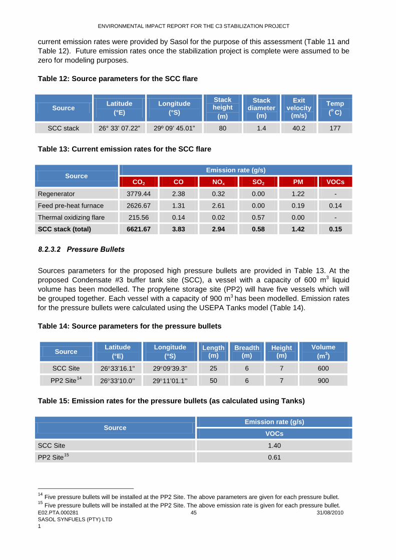
ENVIRONMENTAL IMPACT REPORT FOR THE C3 STABILIZATION PROJECT
E02.PTA.000281 31/08/2010 SASOL SYNFUELS (PTY) LTD 1
45
current emission rates were provided by Sasol for the purpose of this assessment (Table 11 and Table 12). Future emission rates once the stabilization project is complete were assumed to be zero for modeling purposes. Table 12: Source parameters for the SCC flare
Source Latitude (°E)
Longitude (°S)
Stack height
(m)
Stack diameter
(m)
Exit velocity
(m/s)
Temp (o C)
SCC stack 26° 33’ 07.22” 29º 09’ 45.01” 80 1.4 40.2 177
Table 13: Current emission rates for the SCC flare
Source Emission rate (g/s)
CO2 CO NOx SO2 PM VOCs
Regenerator 3779.44 2.38 0.32 0.00 1.22 -
Feed pre-heat furnace 2626.67 1.31 2.61 0.00 0.19 0.14
Thermal oxidizing flare 215.56 0.14 0.02 0.57 0.00 -
SCC stack (total) 6621.67 3.83 2.94 0.58 1.42 0.15 8.2.3.2 Pressure Bullets
Sources parameters for the proposed high pressure bullets are provided in Table 13. At the proposed Condensate #3 buffer tank site (SCC), a vessel with a capacity of 600 m3 liquid volume has been modelled. The propylene storage site (PP2) will have five vessels which will be grouped together. Each vessel with a capacity of 900 m3 has been modelled. Emission rates for the pressure bullets were calculated using the USEPA Tanks model (Table 14). Table 14: Source parameters for the pressure bullets
Source Latitude (°E)
Longitude (°S)
Length (m)
Breadth (m)
Height (m)
Volume (m3)
SCC Site 26°33’16.1" 29°09’39.3" 25 6 7 600
PP2 Site14 26°33’10.0’’ 29°11’01.1’’ 50 6 7 900
Table 15: Emission rates for the pressure bullets (as calculated using Tanks)
Source Emission rate (g/s)
VOCs
SCC Site 1.40
PP2 Site15 0.61
14 Five pressure bullets will be installed at the PP2 Site. The above parameters are given for each pressure bullet. 15 Five pressure bullets will be installed at the PP2 Site. The above emission rate is given for each pressure bullet.
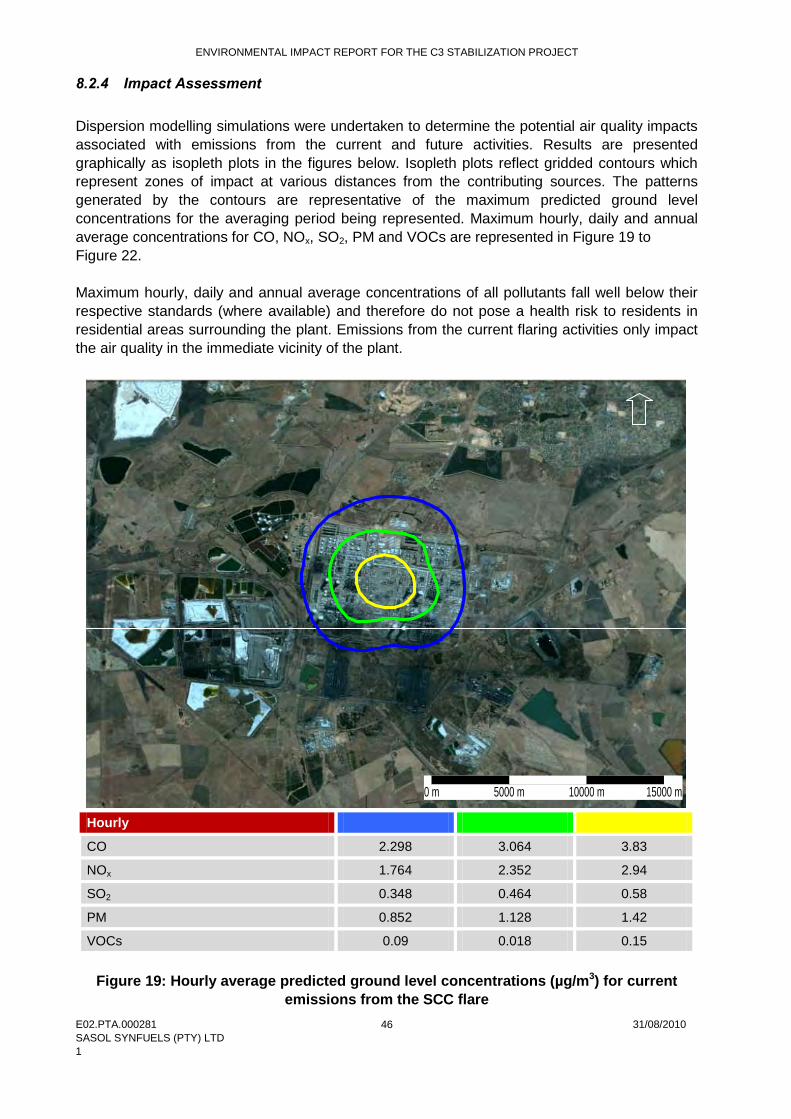
ENVIRONMENTAL IMPACT REPORT FOR THE C3 STABILIZATION PROJECT
E02.PTA.000281 31/08/2010 SASOL SYNFUELS (PTY) LTD 1
46
8.2.4 Impact Assessment Dispersion modelling simulations were undertaken to determine the potential air quality impacts associated with emissions from the current and future activities. Results are presented graphically as isopleth plots in the figures below. Isopleth plots reflect gridded contours which represent zones of impact at various distances from the contributing sources. The patterns generated by the contours are representative of the maximum predicted ground level concentrations for the averaging period being represented. Maximum hourly, daily and annual average concentrations for CO, NOx, SO2, PM and VOCs are represented in Figure 19 to Figure 22. Maximum hourly, daily and annual average concentrations of all pollutants fall well below their respective standards (where available) and therefore do not pose a health risk to residents in residential areas surrounding the plant. Emissions from the current flaring activities only impact the air quality in the immediate vicinity of the plant.
Hourly
CO 2.298 3.064 3.83
NOx 1.764 2.352 2.94
SO2 0.348 0.464 0.58
PM 0.852 1.128 1.42
VOCs 0.09 0.018 0.15
Figure 19: Hourly average predicted ground level concentrations (µg/m3) for current emissions from the SCC flare
0 m 5000 m 10000 m 15000 m
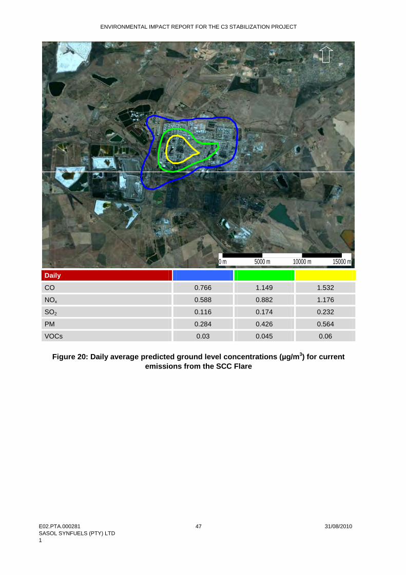
ENVIRONMENTAL IMPACT REPORT FOR THE C3 STABILIZATION PROJECT
E02.PTA.000281 31/08/2010 SASOL SYNFUELS (PTY) LTD 1
47
Daily
CO 0.766 1.149 1.532
NOx 0.588 0.882 1.176
SO2 0.116 0.174 0.232
PM 0.284 0.426 0.564
VOCs 0.03 0.045 0.06
Figure 20: Daily average predicted ground level concentrations (µg/m3) for current emissions from the SCC Flare
0 m 5000 m 10000 m 15000 m
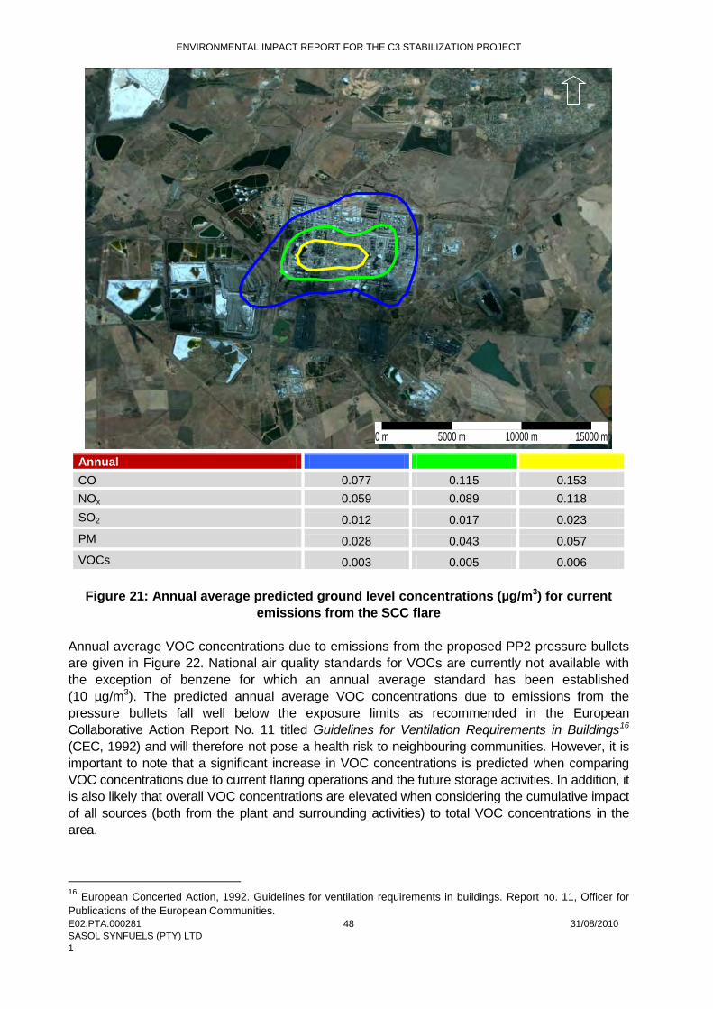
ENVIRONMENTAL IMPACT REPORT FOR THE C3 STABILIZATION PROJECT
E02.PTA.000281 31/08/2010 SASOL SYNFUELS (PTY) LTD 1
48
Annual CO 0.077 0.115 0.153 NOx 0.059 0.089 0.118 SO2 0.012 0.017 0.023 PM 0.028 0.043 0.057 VOCs 0.003 0.005 0.006
Figure 21: Annual average predicted ground level concentrations (µg/m3) for current
emissions from the SCC flare Annual average VOC concentrations due to emissions from the proposed PP2 pressure bullets are given in Figure 22. National air quality standards for VOCs are currently not available with the exception of benzene for which an annual average standard has been established (10 µg/m3). The predicted annual average VOC concentrations due to emissions from the pressure bullets fall well below the exposure limits as recommended in the European Collaborative Action Report No. 11 titled Guidelines for Ventilation Requirements in Buildings16
(CEC, 1992) and will therefore not pose a health risk to neighbouring communities. However, it is important to note that a significant increase in VOC concentrations is predicted when comparing VOC concentrations due to current flaring operations and the future storage activities. In addition, it is also likely that overall VOC concentrations are elevated when considering the cumulative impact of all sources (both from the plant and surrounding activities) to total VOC concentrations in the area.
16 European Concerted Action, 1992. Guidelines for ventilation requirements in buildings. Report no. 11, Officer for Publications of the European Communities.
0 m 5000 m 10000 m 15000 m

ENVIRONMENTAL IMPACT REPORT FOR THE C3 STABILIZATION PROJECT
E02.PTA.000281 31/08/2010 SASOL SYNFUELS (PTY) LTD 1
49
10
20
30
40
Figure 22: Annual average predicted ground level concentrations (µg/m3) for the proposed tanks
8.2.5 Mitigation and Recommendations Pressure tanks are equipped with a pressure/vacuum vent that is set to prevent venting loss from boiling and breathing loss from daily temperature or barometric pressure changes. High-pressure storage tanks can be operated so that virtually no evaporative or working losses occur. There is, therefore, no significant air quality impacts associated with the storage of propylene. However, the on-site storage of propylene does pose a hazard given the nature and properties of propylene. Hazards associated with the storage of such hazardous materials may include a fire hazard, an explosion hazard or the release of toxic fumes, which may result in heat radiation levels, overpressures or over expose to toxic fumes respectively, which may affect personnel, equipment and/or property. The Consequence Impact Study (Appendix F) undertaken for the proposed project indicates that the exposure of personnel to a propylene airborne concentration of 0.1 of the Lower Flammable Limit (LFL) may result in health problems to personnel. Measures to reduce the impacts associated with an explosion include the following considerations: • Reducing the size and density of the pressure bullets as the bigger and more dense the
structure that could be filled with flammable vapour, the more serious the impact and consequences;
• Grouping the propylene bullets with a separation distance of 5 m between the bullets will result in a less severe impact.
ENVIRONMENTAL IMPACT REPORT FOR THE C3 STABILIZATION PROJECT
E02.PTA.000281 31/08/2010 SASOL SYNFUELS (PTY) LTD 1
50
8.3 Impact on Water Resources The potential impacts associated with surface water run-off during the operational phase are anticipated to be low as existing stormwater management structures and sumps will be constructed around the vessels (buffer tank and propylene store) to be able to contain a 1:50 year flood event (i.e. 120 mm rain). This water will then be analysed to determine the destination i.e. stormwater system or if contaminated, it must be released into the SCC oil water sewer system. 8.4 Waste Impacts Waste generation during the operational phase will include: • Oils from the flushing and draining of equipment e.g. pipes. • Redundant equipment. • Wastewater generated from the cleaning of equipment. These impacts are considered to be of low significance as long as they are mitigated by the implementation of the Environmental Management Plan (EMP) – see Appendix H. 8.5 Cumulative Impacts Cumulative impacts assessment represents an emerging process within the broader field of integrated environmental management. Such considerations broaden the spatial and temporal focus of EIAs. Cumulative impacts are commonly understood as the impacts which combine from different impacts and which result in significant change, which is larger than the sum of the all the impacts. The complicating factor is that the project need to be considered from past, present and reasonably foreseeable future development17
(IEM Information Series, Cumulative Effects Assessment, DEAT, 2004).
In terms of the C3 stabilization project, the following cumulative impacts have been identified: • Groundwater impacts as a result of spillage/seepage of condensate #3 into the groundwater
resources. • Soil and groundwater pollution as a result of contaminated stormwater that is not disposed
off correctly.
17 Department of Environmental Affairs and Tourism, 2004. Cumulative Effects Assessment, IEM Information Series.
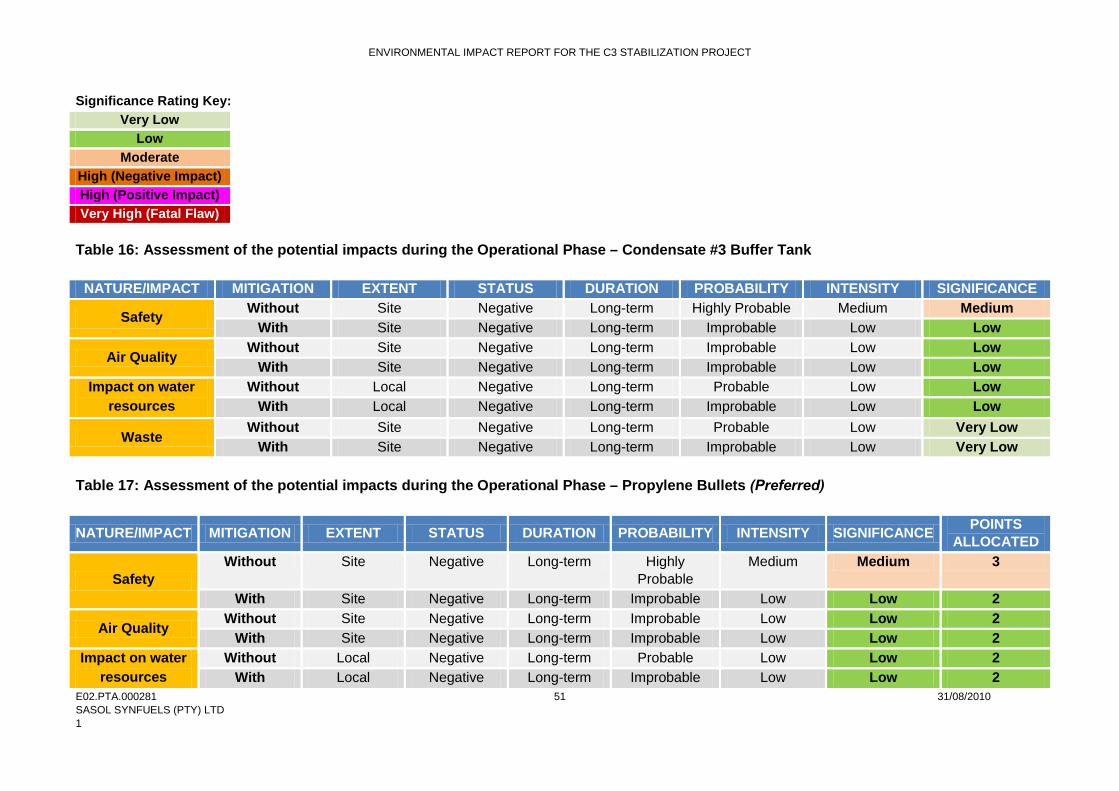
ENVIRONMENTAL IMPACT REPORT FOR THE C3 STABILIZATION PROJECT
E02.PTA.000281 31/08/2010 SASOL SYNFUELS (PTY) LTD 1
51
Significance Rating Key: Very Low
Low Moderate
High (Negative Impact) High (Positive Impact) Very High (Fatal Flaw)
Table 16: Assessment of the potential impacts during the Operational Phase – Condensate #3 Buffer Tank
NATURE/IMPACT MITIGATION EXTENT STATUS DURATION PROBABILITY INTENSITY SIGNIFICANCE
Safety Without Site Negative Long-term Highly Probable Medium Medium With Site Negative Long-term Improbable Low Low
Air Quality Without Site Negative Long-term Improbable Low Low
With Site Negative Long-term Improbable Low Low Impact on water
resources Without Local Negative Long-term Probable Low Low
With Local Negative Long-term Improbable Low Low
Waste Without Site Negative Long-term Probable Low Very Low
With Site Negative Long-term Improbable Low Very Low Table 17: Assessment of the potential impacts during the Operational Phase – Propylene Bullets (Preferred)
NATURE/IMPACT MITIGATION EXTENT STATUS DURATION PROBABILITY INTENSITY SIGNIFICANCE POINTS ALLOCATED
Safety Without Site Negative Long-term Highly
Probable Medium Medium 3
With Site Negative Long-term Improbable Low Low 2
Air Quality Without Site Negative Long-term Improbable Low Low 2
With Site Negative Long-term Improbable Low Low 2 Impact on water
resources Without Local Negative Long-term Probable Low Low 2
With Local Negative Long-term Improbable Low Low 2

ENVIRONMENTAL IMPACT REPORT FOR THE C3 STABILIZATION PROJECT
E02.PTA.000281 31/08/2010 SASOL SYNFUELS (PTY) LTD 1
52
NATURE/IMPACT MITIGATION EXTENT STATUS DURATION PROBABILITY INTENSITY SIGNIFICANCE POINTS ALLOCATED
Waste Without Site Negative Long-term Probable Low Very Low 1
With Site Negative Long-term Improbable Low Very Low 1 Table 18: Assessment of the potential impacts during the Operational Phase – Cold Storage Tanks
NATURE/IMPACT MITIGATION EXTENT STATUS DURATION PROBABILITY INTENSITY SIGNIFICANCE POINTS ALLOCATED
Safety Without Site Negative Long-term Highly
Probable High High 4
With Site Negative Long-term Probable Medium Medium 3
Air Quality Without Site Negative Long-term Improbable Low Low 2
With Site Negative Long-term Improbable Low Low 2 Impact on water
resources Without Local Negative Long-term Probable Low Low 2
With Local Negative Long-term Improbable Low Low 2
Waste Without Site Negative Long-term Probable Low Very Low 1
With Site Negative Long-term Improbable Low Very Low 1 Table 19: Average points allocated to the different design alternatives for the propylene store
PHASE ALTERNATIVES TOTAL (POINTS ALLOCATED)18
Without Mitigation With Mitigation
Operations Propylene Bullets (Preferred) 8 7 Cold Storage Tanks 9 8
18 During the impact assessment the propylene bullets are preferred in terms of environmental criteria. This is also supported from a technical point of view.

ENVIRONMENTAL IMPACT REPORT FOR THE C3 STABILIZATION PROJECT
E02.PTA.000281 31/08/2010 SASOL SYNFUELS (PTY) LTD 1
53
Table 20: Assessment of cumulative impacts during the Operational Phase NATURE/IMPACT MITIGATION EXTENT STATUS DURATION PROBABILITY INTENSITY SIGNIFICANCE
Spillage and seepage of
condensate #3 and propylene
into groundwater
Without Regional Negative Long-term Probable Low Low With Regional Negative Long-term Improbable Low Very Low
Contaminated stormwater
Without Local Negative Long-term Probable Medium Low With Local Negative Long-term Probable Low Low
ENVIRONMENTAL IMPACT REPORT FOR THE C3 STABILIZATION PROJECT
E02.PTA.000281 31/08/2010 SASOL SYNFUELS (PTY) LTD 1
54
9 DECOMMISSIONING PHASE IMPACTS At this point of the project planning process, the necessity for and timing of decommissioning of the project is not known. However, like construction impacts, de-commissioning impacts are inherently temporary in duration. Impacts relating to de-commissioning and rehabilitation activities (demolition, landscaping, compaction etc.) will be addressed within the EMP and it is imperative that a long-term monitoring programme is in place to ensure total rehabilitation of the site after de-commissioning.

ENVIRONMENTAL IMPACT REPORT FOR THE C3 STABILIZATION PROJECT
E02.PTA.000281 31/08/2010 SASOL SYNFUELS (PTY) LTD 1
55
10 CONCLUSIONS AND RECOMMENDATIONS The Environmental Impact Assessment (EIA) process for the proposed C3 stabilization project has been undertaken in accordance with the EIA Regulations published in Government Notice No R385, R386 and R387 of 2006 in terms of Section 24 (5) of the National Environmental Management Act - NEMA (Act No 107 of 1998). In assessing the environmental feasibility of the proposed project, the requirements of relevant legislation have been considered including inter alia those of:
APPLICABLE NATIONAL LEGISLATION The Constitution of South Africa (Act No. 108 of 1996)
The National Environmental Management Act (Act No. 107 of 1998) Atmospheric Pollution Prevention Act (Act No. 45 of 1965)
National Environmental Management: Air Quality Act (Act No. 39 of 2004) The National Water Act (Act No. 36 of 1998)
Occupational Health and Safety Act-Major Hazard Installation Regulations (GN R692, July 2001)
National Environmental Management: Waste Act (No. 59 of 2008) Health Act (Act No. 63 of 1977)
National Heritage Resources Act (No 25 of 1999) and Regulations This relevant legislation has informed the identification and development of appropriate management and mitigation measures that should be implemented in order to minimise potentially significant impacts associated with the project. The conclusions of this draft Environmental Impact Report (EIR), including comments and concerns from Interested and Affected Parties (I&APs), are as a result of a comprehensive EIA study. These studies are based on issues identified in the Environmental Scoping phase and the parallel process of public participation through to the EIA phase. The public consultation process has been comprehensive, and every effort has been made to include representatives of all stakeholders within the process. 10.1 Evaluation of the Proposed Project The preceding chapters of this report provide a detailed assessment of the potential environmental impacts on specific components of the social and biophysical environment as a result of the proposed project. This chapter concludes the EIA report by providing a holistic evaluation of the most important potential environmental impacts identified through the EIA process.
During this EIA study the following alternatives were considered: 10.1.1 Condensation #3 Buffer Tank – Two site alternatives i.e. SCC plant and HP tank farm. During the impact assessment both alternatives ranked the same in terms of environmental criteria. However, from a technical point

ENVIRONMENTAL IMPACT REPORT FOR THE C3 STABILIZATION PROJECT
E02.PTA.000281 31/08/2010 SASOL SYNFUELS (PTY) LTD 1
56
of view, the installation of the buffer tank in the HP tank farm is not preferred due to the following reasons:
− Very long lines to and from vessel, making the installation very expensive and very impractical.
− Possible increase in pump capacity, which can result in more pumps being required. − Pressure control in the vessel will be more complicated and might result in additional
equipment requirements. 10.1.2 Propylene Storage Facility Two design alternatives were considered during the EIA study i.e. the installation of bullets or two cold storage tanks. From an environmental perspective the installation of bullets was preferred compared to the installation of two tanks. The installation of two tanks is not preferred due to the following:
− The bigger the structure and more dense the structure that could be filled with flammable vapour the more serious the impacts and consequences from a safety perspective.
− Larger volume of propylene stored. − Very high energy demand, therefore very high operational cost. − Equipment intensive.
10.2 Concluding Remarks This draft EIA Report provides an assessment of both the benefits and potential negative impacts anticipated as a result of the proposed C3 stabilization project. The findings conclude that there are no environmental fatal flaws that could prevent the proposed project from proceeding, provided that the recommended mitigation and management measures are implemented. Thus, from all the findings of this report, it is recommended that the proposed project be approved. In addition is it recommended that the following alternatives are approved: • Condensate #3 tank preferred site – SCC plant (S 26°33’16.1’’; E 29°09’39.3’’). • Propylene Storage Facility – preferred site at the area west of the PP2 plant
(S 26°33’10.0’’; E 29°11’01.1’’) and the preferred design consisting of 5 vessels (bullets).
This is the view and recommendation of the Environmental Assessment Practitioner based on the findings of this Environmental Impact Assessment. 10.3 Final Recommendations In order to achieve appropriate environmental management standards and ensure that the findings of the environmental studies are implemented through practical measures, the recommendations from this EIA are included within an EMP (refer to Appendix H). The EMP would be used to ensure compliance with environmental specifications and management measures. The implementation of this EMP for all life cycle phases (i.e. construction, operation and de-commissioning) of the proposed project is considered to be key in achieving the appropriate environmental management standards as detailed for this project.