ENVIRONMENTAL IMPACT ASSESSMENT...
295
For Obtaining MoEF and CRZ Clearance for Proposed Multi Modal Corridor from Navghar to Chirner (near JNPT) ENVIRONMENTAL IMPACT ASSESSMENT REPORT January, 2017
Transcript of ENVIRONMENTAL IMPACT ASSESSMENT...

For Obtaining MoEF and CRZ Clearance for Proposed Multi Modal Corridor from Navghar to Chirner (near JNPT)
ENVIRONMENTAL IMPACT
ASSESSMENT REPORT
January, 2017


i | P a g e
TABLE OF CONTENTS
CHAPTER- 1: INTRODUCTION ............................................................................................................ 1-1
1.1 General ...................................................................................................................................... 1-1
1.2 The Project ................................................................................................................................ 1-1
1.3 Purpose of Report ..................................................................................................................... 1-1
1.4 Objective of Multi Modal corridor ............................................................................................... 1-1
1.5 Objectives of the EIA ................................................................................................................. 1-3
1.6 Project Benefits ......................................................................................................................... 1-4
1.7 Identification of the Project and Project Proponent .................................................................... 1-4
1.8 Scope of Services ...................................................................................................................... 1-5
1.9 Environmental Clearance .......................................................................................................... 1-6
1.10 Structure of the EIA Report ........................................................................................................ 1-6
LIST OF TABLES
Table 1.1 Scope of Environmental Analysis, Design and Environmental Management Action Plan 1-5
LIST OF FIGURES
Figure 1.1: Alignment Route of Propose MMC Corridor ......................................................................... 1-3


1-1 | P a g e
CHAPTER- 1: INTRODUCTION
1.1 General
The purpose of this chapter is to introduce the scope and objective of the project works in general
and EIA and EMP in particular within which the detailed Environmental Assessment studies of
Multi Modal corridors have been carried out. This chapter also discusses the nature, size, location
of the project along with brief structure of the EIA reports.
1.2 The Project
Multi Modal corridor has been planned to cater need of growing population along fringe areas.
Other objective of the project is to provide connectivity to industrial and commercial establishment
in SEZ area to residential areas of satellite towns of Mumbai Metropolitan region with diverse mode
of transport. The proposed MMC alignment is take off from km 490.075 of NH-8 near Navghar
and ends it open agriculture land near Chirner village (near JNPT). The Project alignment is
traversing through Palghat, Thane and Raigad District in the State of Maharashtra. The Total
Length of the Phase-1Project Mumbai Multi Modal Corridor is approx. 80 Km. The MMC alignment
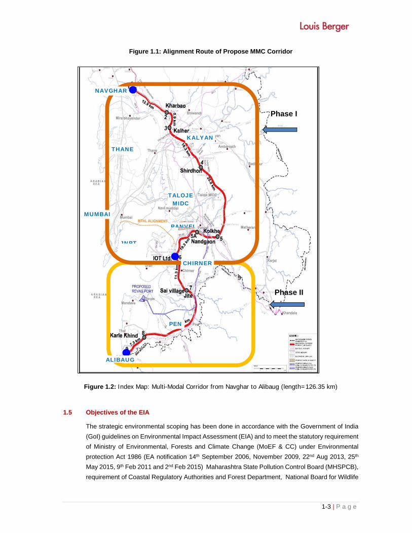
along with MMC phases are presented in Figure 1.1 and 1.2 respectively.
1.3 Purpose of Report
This Environmental Impact Assessment Report is prepared to ensure that decision makers
consider the environmental impacts when deciding whether or not to proceed with a project.
Environmental Impact Assessment is a process of identifying, predicting, evaluating and mitigating
the biophysical, social, and other relevant effects by developing MMC project prior to major
decisions being taken and commitments made.
This report has been prepared in accordance with all relevant laws and regulations of the
Government of India, MoEF & CC, MHPCB, and CPCB. The key purpose of this EIA report is to:
• Predict all environmental concerns and associated impacts due to construction and operation
of Multi Modal corridor within the COI
• Evaluate any sensitive receptors going to be impacted by the project within the 10 km radius
from the MMC alignment
• Recommended strategies and action to minimize, avoid and mitigate these environmental
concern and Enhancement of positive effects.
1.4 Objective of Multi Modal corridor
The main objectives of the project (i) is to cater need of growing population along fringe areas, (ii)
establish the technical, economic and financial viability of the MMC project, and (iii) prepare an
EIA Report for the construction and operation of metro-rail and six lane highways (Multi Modal
Corridor) from Navgarh to Chirner so that development will become environmentally sound,
sustainable and people friendly. The MMC alignment along with MMC phases are presented in
Figure 1.1 and 1.2 respectively.

1-2 | P a g e
1-3 | P a g e
Figure 1.1: Alignment Route of Propose MMC Corridor
Figure 1.2: Index Map: Multi-Modal Corridor from Navghar to Alibaug (length=126.35 km)
1.5 Objectives of the EIA
The strategic environmental scoping has been done in accordance with the Government of India
(GoI) guidelines on Environmental Impact Assessment (EIA) and to meet the statutory requirement
of Ministry of Environmental, Forests and Climate Change (MoEF & CC) under Environmental
protection Act 1986 (EA notification 14th September 2006, November 2009, 22nd Aug 2013, 25th
May 2015, 9th Feb 2011 and 2nd Feb 2015) Maharashtra State Pollution Control Board (MHSPCB),
requirement of Coastal Regulatory Authorities and Forest Department, National Board for Wildlife
Chir
Alib
Phase II
9
KALYAN
THANE
PANVEL
JNPT
TALOJE MIDC
PEN
1 -
NAVGHAR
ALIBAUG
CHIRNER
MUMBAI
Phase I

1-4 | P a g e
(NBWL) Govt. of India etc. The objectives of this study is stated below:
• To present a clear assessment of potential impact associated with the proposed project
intervention,
• To apply a methodology which assesses and predict potential impacts and provides a) the
means for impact prevention and mitigation, b) the enhancement of project benefits, and c) the
minimization of long-term impacts;
• To provide a specific forum in which consultation is systematically undertaken in a manner that
allows stakeholders to have direct input to the environmental management process.
• To minimize any adverse impact on forest and wildlife sanctuary
• To minimize the land acquisition in sensitive areas Including forest and wildlife
• To analysis the alternatives to bring environmental considerations into the upstream stages of
development planning as well as the later stage of site selection, design and implementation,
and
• To recommend the environmental and social management measures to reduce adverse
impacts.
1.6 Project Benefits
As mentioned in earlier section also the proposed project will bring unhindered and free movement
of goods and traffic (mainly daily commuters) from various residential areas to upcoming growth
centers in SEZ areas. The implementation of the project will have the following direct benefits:
(i) Improved quality of life for the population in the project area.
(ii) Economic boost to the local population because of improvement of connectivity and change in
occupational Pattern.
(iii) Improvement will provide better connectivity for other towns and cities to SEZ area.
(iv) Provides employment facility for the local population during construction period.
(v) Development of growth centers will provide development of basic industries.
(vi) Connectivity to JNPT(Navaseva) port and other transport corridor
(vii) Minimize the travel time, exhaust emission from vehicle as compared to the improved and
better convectively
1.7 Identification of the Project and Project Proponent
MMRDA, Government of Maharashtra has planned to development Multi Modal corridor to cater
need of growing population along fringe areas. Other objective of the project is to provide
connectivity to industrial and commercial establishment in SEZ area to residential areas of Mumbai
region with diverse mode of transport. MMRDA has identified Navgarh to Chirner section as priority
sector as a complementary link to various transport networks in Mumbai region. In order to fulfil
the above task, MMRDA has appointed M/s Louis Berger Group, Inc., USA as Consultants to
Prepare EIA report to obtain the Environmental clearance from Ministry of Environment, Forest

1-5 | P a g e
and Climate Change (MoEF & CC).
1.8 Scope of Services
Scope of Environmental Impact Assessment
The EIA for project includes establishing environmental baseline in the study area, identify the
range of environmental impacts, specify the measures to avoid, minimize, and mitigate negative
impacts and maximize positive impacts and integrate possible environmental enhancement
measures. The proposed measures will be formulated in the form of an environmental
management plan with necessary budget and institutional roles for effective implementation. The
EMPs for individual projects and integration of the same in to project implementation agreements,
including construction contract documents.
Environmental Management Plan: An Environmental Management Plan has been prepared for the
implementation of the project. The environmental management plan shall consists of overall
framework which will be developed as a guiding document providing environmental planning and
design criteria for the current as well as future project roads, generic environmental management
measures, institutional mechanism for implementation, capacity building and training process,
function adequately to mainstream the environmental management. To recommend further studies
on environmental aspects, which are required to be undertaken during project implementation, if
required
The objectives of EIA for this project include the following
• Collection of baseline data on various components of the environment.
• Identification of areas and aspects those are environmentally or socio-economically significant.
• Development of the road alignment broadly ensuring that the environment and settlements are
affected the least.
• Conduction and documentation of community consultation on various aspects of the project
with respect to environment.
• Preparation of environmental management plans for enhancing the positive impacts and
mitigating the negative impacts.
• Determination of the magnitude of environmental impacts so that due consideration is given
to these during planning / design, construction and operational phases of the project
implementation.
Table 1.1 has given brief description of Environmental scoping
Table 1.1 Scope of Environmental Analysis, Design and Environmental Management
Action Plan
Environmental Analysis
To carry out a preliminary environmental screening of the proposed corridor to determine the magnitude of actual and potential impacts and ensure that environmental considerations are given adequate weightage in the selection and design of the proposed improvement;
To collect information on existing environmental baseline conditions and undertake a preliminary evaluation of the alignment selected for

1-6 | P a g e
construction in order to define the focus of the environmental assessment, design and management studies
To identify positive and negative impacts of the proposed improvement and to propose cost-effective measures to enhance positive impacts and to avoid and / or mitigate negative impacts;
To carry out Public Consultations with concerned stake holders, affected persons/families and NGOs
Environmental Design
From Environment Assessment, to identify adverse impacts such as soil erosion, loss of flora, fauna, water resources, physical resources etc. and prevent them through judicious design changes by adopting appropriate mitigation measures such as plantation of trees, installation of proper drainage system, adequate safety measures for human & animal habitats near or along the proposed corridor, provision of suitable mitigation measures etc.
Prepare cost – effective proposals to implement appropriate mitigation and remedial measures to upgrade and enhance the environmental quality along the corridor in a sustainable manner; and
Selecting stretches along the corridor, which provides opportunity for environmental enhancement and the development of cost-effective sustainable environmental assets.
Environmental Management Action Plan
To prepare an implementation schedule and supervision program with associated costs and contracting procedures for the execution of environmental mitigation and design works;
To develop a program for monitoring environmental impacts during construction and operational phases;
To spell out specific requirements for institutional strengthening and training needs; and
To recommend further studies on environmental aspects, which are required to be undertaken during project implementation, if required.
1.9 Environmental Clearance
As per the EIA notification of 14th September 2006, its amendment dated 1st December 2009, and
22 Aug 2013, this project is fall under category A because the majority of proposed alignment of
the project is passes through green field and proposed ROW for the corridor is warries from 45
mtrs to 126 mtrs at locations as per design demand and in general it is 99 m. The proposed corridor
is passes through Sanjay Gandhi National Park, and other environmental sensitive areas which
are coming within their respective buffer zones are Tungreshwar Wildlife sanctuary, Karnala bird
sanctuary and Matheran eco-sensitive zone (notified as critically polluted industrial area).
1.10 Structure of the EIA Report
The EIA report, excluding chapter 1, has been structured into the following chapters:
Chapter 2: PROJECT DESCRIPTION
Provide the description of the project which includes location, type, need and purpose of the
project.
Chapter 3: DESCRIPTION OF THE ENVIRONMENT
It presents the existing baseline status of the project influence area and is constituted into two
parts viz. brief methodology is presented in first part and baseline conditions are presented in
second part of the chapter.
Chapter 4: ANTICIPATED ENVIRONMENTAL IMPACTS & MITIGATION MEASURES

1-7 | P a g e
Describes the environmental setting of the project area baseline conditions relating to meteorology,
physical environment, water resources, noise, air as well as flora and fauna.
Chapter 5: ANALYSIS OF ALTERNATIVES
Discusses the criteria for identification and analysis of alternatives, description of various
alternatives including “No Change” alternative.
Chapter 6: ENVIRONMENTAL MONITORING PLAN
To ensure the effective implementation of the EMP, it is essential that an effective monitoring
programme be designed and carried out. So that envisaged purpose of the project is achieved and
results in the desired benefit to the target population.
Chapter 7: ADDITIONAL STUDIES
Summaries the consultations/discussions held with the public at different levels e.g. villagers,
project affected persons (PAPs), and other stakeholders such as Govt. Officials, during the project
preparation stage to record people’s perceptions of the project and potential impacts.
Chapter 8: PROJECT BENEFITS
Gives brief description of the mitigation and enhancement measures opted for the project.
Chapter 9: ENVIRONMENTAL BENEFIT ANALYSIS
Environmental budget for the various environmental management measures proposed in the EMP
at construction and operation stages are summarized in this chapter.
Chapter 10: ENVIRONMENTAL MANAGEMENT PLAN
Provide Cost effective environmental management plan to eliminate/ offset the identified
environmental impact, so that development will become environmentally sound.
Chapter 11: SUMMARY AND CONCLUSION
Provides a brief summary of all the chapters that are detailed in the EIA and EMP Report along
with the baseline study, impacts, budget and Management plan.
Chapter 12: DISCLOSURE OF CONSULTANTS ENGAGED


i | P a g e
TABLE OF CONTENTS
CHAPTER- 2: PROJECT DESCRIPTION .............................................................................................. 2-1
2.1 TYPE OF THE PROJECT .......................................................................................................... 2-1
2.2 PROJECT CATEGORY ............................................................................................................. 2-1
2.3 NEED FOR THE PROJECT ....................................................................................................... 2-1
2.4 PROJECT LOCATION ............................................................................................................... 2-2
2.5 FEATURE OF THE PROJECT ................................................................................................... 2-5
2.5.1 Right of Way (ROW) ...................................................................................................... 2-5
2.5.2 Proposed Interchanges: ................................................................................................. 2-8
2.5.3 Underpass ......................................................................... Error! Bookmark not defined.
2.5.4 Service Road ............................................................................................................... 2-10
2.5.5 Fly Over ............................................................................ Error! Bookmark not defined.
2.6 PROPOSED RAIL-ROAD CROSSINGS ................................................................................... 2-10
2.7 TRAFFIC ................................................................................................................................. 2-11
2.7.1 Traffic Demand Forecast Methodology for the MMC .................................................... 2-11
2.7.2 Traffic Data Collection Plan ......................................................................................... 2-11
2.7.3 Traffic Study Conclusions ............................................................................................ 2-12
2.7.4 Creating the MMC EMME Database ............................................................................ 2-12
2.8 ROAD ACCESSORIES ............................................................................................................ 2-13
LIST OF TABLES
Table 2.1: Interchange along the MMC ................................................... Error! Bookmark not defined.
Table 2.2: Proposed location of VUP along MMC ................................... Error! Bookmark not defined.
Table 2.3: Proposed location of Pedestrian Underpass along the MMC Error! Bookmark not defined.
Table 2.4: List of proposed major and minor bridges along the MMC ... Error! Bookmark not defined.
Table 2.5: List of proposed fly over along the MMC ................................ Error! Bookmark not defined.

2-1 | P a g e
CHAPTER- 2: PROJECT DESCRIPTION
The purpose of this chapter is to describe the need of the project, purpose of the report, project
location and proposed improvement activities in general for which EIA and EMP have been carried
out.
2.1 TYPE OF THE PROJECT
A Multi Modal Corridor is a single corridor in which multiple modes, such as buses, BRT, metro rail
and cars, along with utilities such as water, sewage and gas lines are present in the same Right of
Way. The Right of way (ROW) of Proposed Multi Modal Corridor is 99 meters.
The MMC was envisaged to provide connectivity to existing and future growth centers in the MMR
(Mumbai Metropolitan Region). The MMC will help the growth of 7 growth centers viz. Virar,
Bhiwandi, Kalyan, Dombivali, Panvel, Uran and Taloja MIDC in the MMR Region. It would provide
faster connectivity between the Urban Local Bodies (ULBs) located outside Greater Mumbai and
improve accessibility to inter-city freight traffic.
The MMC will connect the major roads such as NH-8, Bhiwandi bypass, NH-3, NH-4, NH-4B,
Mumbai Pune Expressway, NH-17 etc. The Corridor will provide faster connectivity to JNPT,
Proposed Navi Mumbai Airport, MTHL Project and Dedicated Freight Corridor (DFC).
The Project area traverses through the plain and rolling terrain and passes through Palghar, Thane
and Raigad district of Maharashtra. The Corridor is running parallel to Bassien Creek up to Ulhas
River (near Kalher).
2.2 PROJECT CATEGORY
After thorough study of MoEF notification September 2006 its amendment 2009 and 22 Aug 2013,
it is learnt that the item required for the improvement of highways is mentioned in Para 7(f) of MoEF
notification matrix which stated that if road length is upto 100 km involving additional right of way
or land acquisition up to 40 mts on existing alignments and 60 mts on re-alignments or by-passes
may be exempted from the preview of the notification. However, MMC project length is about 80
km with proposed ROW warries from 45mt to 126mt at locations and in general it is 99 m, alignment
passes through Sanjay Gandhi National Park and traverses through 153 m away from
Tungareshwar wildlife sanctuary & 900 m away from the boundary of Karnala bird sanctuary and
also falling within the protected radius of Matheran Eco-sensitive Zone. Hence, this project falls
under category A, therefore, environmental clearances is required from MoEFCC.
2.3 NEED FOR THE PROJECT
A Comprehensive Transportation Study (CTS) for the Mumbai Metropolitan Region (MMR), which
is also known as TRANSFORM (Transportation Study for the region of Mumbai) was conducted
by the Mumbai Metropolitan Region Development Authority (MMRDA) in consultancy with M/s Lea
International Limited and technical assistance from World Bank under the Mumbai Urban Transport
Project (MUTP) in July 2008. This Study provided the recommendation for planned development
of transport system in MMR for the period up to 2031.
The CTS objectives were to ensure the following:

2-2 | P a g e
A competitive MMR
A livable MMR
A bankable MMR
A well governed MMR
Working towards above objective, the TRANSFORM was conducted to identify the travel pattern
of residents in the MMR. The aim was to provide seamless connectivity between the different
MMR areas such that people can travel from their origins to destinations within a reasonable
amount of time. One of the recommendations of TRANSFORM was to develop the Multi Modal
Corridor (MMC) from Virar to Alibaug, also known as the Middle Ring.
As per the World Bank MUTP implementation support mission during 23rd July to 6th August,
2008, it was proposed to obtain consultancy services for carrying out a “Feasibility study with
alternatives analysis of a priority Multi-Modal Corridor from Virar to Alibaug”. The study includes
the following stages.
Alternative Analysis.
Detailed Planning and Preliminary Engineering
Implementation of the project within the time frame.
Funding plan like PPP (Public Private Partnership) or public frame.
MMRDA has completed the Techno Economic and Financial Feasibility Study for the Multi Modal
Corridor by appointing Consultants M/s Louis Berger Group, Inc. (LBG) in March 2012. As per
consultants (LBG’s) recommendation, the corridor is proposed to be commissioned in two Phases:
Phase I- Navghar to Chirner near JNPT about 79 Km and
Phase II- Chirner near JNPT to Alibaug about 47 km.
MMRDA has now initiated Phase I of the Project for Obtaining MoEF and CRZ Clearance from
Navghar to Chirner (near JNPT) i.e. about 80 kms and Environmental clearance assignment was
awarded to Louis Berger in July 2014.
2.4 PROJECT LOCATION
The project alignment is traversing through Palghar, Thane and Raigad Districts in the State of
Maharashtra. The Total Length of the Project (Mumbai Multi Modal Corridor) is approx. 80 Km.
and the entire length of the project alignment is divided into 6 sections detailed below:
Table 2.1: MMC Revised Alignment (After TEFS Study - Revision # 1)
Section
Landmark Chainage
Length (Km) From To From To
1-2 Navghar Dunge 00+000 12+900 12.900 2-3 Dunge Kalher 12+900 18+800 5.900 3-4 Kalher Hedutane Gaon 18+800 35+100 16.300
4-5 Hedutane Gaon Kolkhe Gaon 35+100 60+685 25.585
5-6 Kolkhe Goan Chirner 60+685 80.336 19.651

2-3 | P a g e
Figure 2.1 presents the further Refinement of Alignment in Section 5-6, to address CIDCO issues in relation to Airport R&R pockets and Pushpaknagar Development Plan. After this exercise, MMRDA Finalized the Alignment presented in Figure 2.1 and Table 2.1 as Approved Alignment (White Alignment) and the same was introduced in 27 Villages Development Plan through Special Notified Planning Authorities (SNPA) for Kalyan, Dombivali and Ulhasnagar Municipal Corporation.
Figure 2.1: Refined Alignment
Since Multi-Modal Corridor and the Mumbai-Vadodara-Expressway (MVE) are running parallel in City & Industrial Development Corporation of Maharashtra Ltd (CIDCO), it was decided to combine both the corridor and National Highways Authority of India (NHAI) will develop the corridor from Morbe (km 47.70) to Karanjade (km 66.60).
The Section 1-2 of the MMC alignment (approx. 12.900 Km) starts from the junction of NH8
(Navghar) and the Diva Vasai Rail line and runs parallel to Diva Vasai Rail Line / Kaman village
and ends near Kharbav Railway Station/Dunge Village.

2-4 | P a g e
The Section 2-3 of the MMC alignment (approx. 5.900 Km) starts near Kharbav Railway
Station/Dunge Village and ends near Kalher Reti Bunder passing through Dive Village
Gavthan.
The Section 3-4 of the MMC alignment (approx. 16.300 Km) starts near Kalher Reti Bunder
and ends at Shidhon Village near Hedutane Gaon passing through Alimghar Village, Ulhas
River, west of Sandap Gaon and Kolegaon.
The Section 4-5 of the MMC alignment (approx. 25.585 Km) starts at Shidhon Village near
Hedutane Gaon and ends near Kolkhe Village (near Panvel /Mumbai Pune Express Highway)
passing through Utasane Village, Mahulangi Village and Wangani Village.
Figure 2.2: Final Alignment for Detailed Study

2-5 | P a g e
The Section 5-6 of the MMC alignment (approx. 19.700Km) runs from Kolkhe Village (near Panvel / Mumbai Pune Express Highway) and ends at Chirner near JNPT running parallel to NH 4 B passing through Nandgaon and Chirle Gaon.
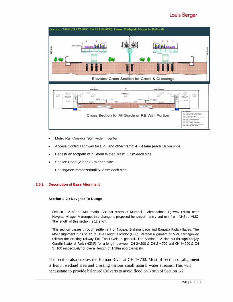
2.5 FEATURE OF THE PROJECT
2.5.1 Right of Way (ROW)
The MMC in general proposed with a Right of Way 99 m to accommodate access controlled
highway lanes, service lanes, parking lane, pedestrian foot path and a metro facility at the Center
(30 m). ROW details are presented in Table 2.2. The conceptual cross section of the MMC is
presented in Figure below:
TEFS Cross Section

2-6 | P a g e
Alignment length of around 1.4 kms is passes through Sanjay Gandhi National Park by considering that from Km 0+000 to km 6+000 the ROW is reduced to 45m and to avoid any direct encounter between Wildlife and traffic or minimize any adverse impact with in the SGNP, a tunnel and elevated corridor is proposed in this section. Elevated cross section is also proposed on creek and mangrove area.
Table 2.2: ROW details
Sr # Chainage Length
(Km) ROW (m) Near Landmarks
Start End
1
0+000
6+000 6.00 45.00 From NH8 (Mumbai - Ahmedabad National
2
6+000
46+900 40.90 99.00 From Nagale to Morbe
3
46+900
66+225 19.33 126.00 Combined ROW: MVE & MMC from Morbe to Karanjade

2-7 | P a g e
4
66+225
69+030 2.81 69.50 Airport R & R Pocket Near Karanjade
5
69+030
70+200 1.17 99.00 D Point - Hill
6
70+200
72+000 1.80 69.50 Pushpak Nagar Near Manghar
7
72+00
98+000 26.00 99.00 From Pushpak Nagar to Balavali
Figure 2.3 showing Cross section of MMC in Sanjay Gandhi National Park
2-8 | P a g e
Metro Rail Corridor: 30m wide in center,
Access Control Highway for BRT and other traffic: 4 + 4 lane (each 16.5m wide )
Pedestrian footpath with Storm Water Drain: 2.5m each side
Service Road (2 lane): 7m each side
Parking/non-motorized/utility: 8.5m each side
2.5.2 Description of Base Alignment
Section 1-2 : Navghar To Dunge
Section 1-2 of the Multimodal Corridor starts at Mumbai - Ahmadabad Highway (NH8) near Navghar Village. A trumpet interchange is proposed for smooth entry and exit from NH8 to MMC. The length of this section is 12.9 Km.
This section passes through settlement of Nagale, Brahmangaon and Bangala Pada villages. The MMC alignment runs south of Diva Freight Corridor (DFC). Vertical alignment of MMC carriageway follows the existing railway Rail Top Levels in general. The Section 1-2 also cut through Sanjay Gandhi National Park (NGNP) for a length between CH 2+200 & CH 2 +700 and CH 4+200 & CH 5+100 respectively for overall length of 1.5Km approximately.
The section also crosses the Kaman River at CH 1+700. Most of section of alignment is lies in wetland area and crossing various small natural water streams. This will necessitate to provide balanced Culverts to avoid flood on North of Section 1-2

2-9 | P a g e
The following structures are proposed in Section 1-2:
10 Nos. Major Bridges 7 Nos. Minor Bridges 3 Nos. Vehicular Underpasses (VUP) 2 Nos. Pedestrian Underpasses (PUP) 21 Nos. Culverts 2 Nos. Foot over Bridges (FOB)
Section 2-3 : Dunge to Kalher
Section 2-3 of the Multimodal Corridor starts on the west of Dunge village and passes through an 80m wide tributary of Ulhas River. The length of this section is 5.9 Km. The section passes through settlements (villages) namely Vadghar, Kewani, Purna and Rahanal. The following
structures are proposed in Section 2-3:
4 Nos. Major Bridges 3 Nos. Minor Bridges 2 Nos. Vehicular Underpasses (VUP) 10 Nos. Culverts
Section 3-4 : Kalher to Hedutane Gaon
Section 3-4 of the Multimodal Corridor runs parallel to the Ulhas River to east and crosses the river between Diva and Dombivali towards Hedutane Gaon. The length of this section is 16.30 km. This section serves settlements, such as, Kalher, Kasheli, Anjurd, Mankoli, Diva, and Hedutane Gaon. Other major habitation around the influence area of section 3-4 consists of Bhiwandi, Kalyan, Ulhasnagar, Airoli, Ghansoli, Mumbra, Dombivali. Mankoli, Kalher and Kasheli areas are mainly Industrial and Container Terminal Centers. The following structures are proposed in Section 3-4:
2 Nos. Flyovers of 4200m and 1610m length respectively 2 Nos. Major Bridges of length 900m and 100m 1 No. Minor bridge of 50m length 5 Nos. Vehicular Underpasses VUP 9 Nos. Pedestrian Underpasses PUP 9 Nos. Balanced Cculverts Cloverleaf Interchange is proposed to provide connectivity to Kalyan Shil-Phata Road &
Katai-Ambernath-Badlapur Road.
Section 4-5 : Hedutane Gaon to Kolkhe Gaon Section 4-5 mainly passes through green field area. The length of this section is 25.585 Km. Major Settlements are located towards the west of the MMC alignment along the suburban railline and National Highway 4. This include: Kharghar, Navade, Kalamboli, Asudgaon and Panvel The following structures are proposed in Section 4-5.
4 Nos. Major bridges, 3 Nos. Minor bridges, 26 Nos. Culverts, 16 Nos. Vehicular Underpasses (VUP) and 8 Nos. Pedestrian Underpasses (PUP)
2-10 | P a g e
Section 5-6 : Kolkhe Gaon to Chirner (JNPT) Section 5-6 of the Multimodal Corridor runs along the JNPT road (NH4B) towards Uran. The length of this section is 19.651 Km. This section passes through various village settlements and proposed development areas such as Panvel, Bamandonrgi, NAINA, CIDCO etc. This section crossing Panvel - Pune & Panvel - Agra Railway Lines. This section also crossing Mumbai - Pune Expressway, NH4 and Panvel Byepass. The major section runs parallel to NH4B. The various realignment alternatives have been studied for realignment between CH 54+000 & CH 61+000 and CH 73+900 & CH 74+900 and presented in subsequent section of this report. The Mumbai-Vadodra Expressway Spur is running parallel MMC from Morbe (CH 47+7750) to Karanjade (CH 65+500). The combined Right of Way (ROW) of MMC and Mumbai-Vadodra Expressway Spur would be 126.00m wide for this particular section. NHAI has taken Mumbai-Vadodra Expressway Spur work on priority. The land acquisition of this section is being carried out.
MMRDA submitted the MMC base alignment to NHAI vide Letter D/MMRDA/MMC/Alignment/2016 dated
08/03/2016. NHAI has informed MMRDA vide letter NHAI/VME/PIU/Panvel/2016/2391 of 29.01.2016 that MMC and Mumbai Vadodra Expressway shall be developed by NHAI from CH 47+750 to CH 65+500.
2.5.3 Service Road
Service roads are provided all along the MMC to facilitate cross traffic movement from main
carriageway through underpasses and bridges and for local traffic movement. Service road level
is kept 1.5 to 2m above ground level/standing water level.
Drainage
Drainage of the road is a major issue and concerns cross drainage as well as side drainage, which
deals with keeping the embankment clear of water that may damage the pavement by entering
into the embankment and the pavement layers. Side drainage in this context is defined as the
drainage that protects the road including its embankment and especially the pavement from
being submerged for longer period of time. The side drains have to catch the water that is falling
on the road or floating towards the road and discharge the water to the cross drainage-being
rivers and streams for which bridges, CD structures and culverts are provided. For the road
carriageway and the service roads gutter type of drains will be provided on both sides between
the service road and the MMC to collect and discharge the water falling on the road carriageway
and service road. For the surrounding area channel will be provided which intercept water
reaching before the service road. The channel will be partly open and partly closed. All along the
corridor total 106 culverts will be provided for smooth flow of water from one side of alignment to
other side.
2.6 PROPOSED RAIL-ROAD CROSSINGS
The Proposed Project crosses existing railway line at 3 locations. The details of railway crossings
are given below:

2-11 | P a g e
Central Rail Line at Ch 27+450 Km near Bhopar Goan
Konkan Rail Line at Ch 59+ 250 Km near Sangade Village
Konkan Rail Line Ch 62+300 Km near Derawali Village.
2.7 TRAFFIC
2.7.1 Traffic Demand Forecast Methodology for the MMC
Step by step modelling procedure has been briefed below for evaluation of the potential travel
demand of MMC:
Create a EMME databank based on the general characteristics of the MMRDA database
(dimensions) and using the “punched out” files obtained from MMRDA using EMME Modules 2
(networks and transit lines, turn tables, etc.), Module 3 (demand matrices) and Module 4 (vdf, turn
penalty and ttf functions).
Create a MMRDA base scenario for 2031 using E3P3 demand and corresponding networks;
Create (coding) a MMC network scenario describing the network and transit supply contemplated
in the multi modal corridor. At this stage, a single scenario reflecting the general alignment of the
MMC centerline is considered. Centerline alternatives in subsections of the MMC are not modeled
since they marginally impact the global demand in the corridor
Analyze absolute traffic and transit figures in the MMC corridor, compare relative performances of
traffic and transit network scenario (base and MMC).
Eventually, refine the network, transit lines, volume delay and transit time functions codification to
improve the representation of the MMC physical and operational characteristics of the road and
transit. Punch out the corresponding EMME files and input in the MMRDA database and run the
global transport demand model.
2.7.2 Traffic Data Collection Plan
This portion of the report deals with the Traffic Data collection with details on Traffic count and
Origin-Destination Surveys conducted and their results.
The traffic count and Origin-Destination survey was conducted at 7 major locations. These
locations were selected considering the major highways with maximum traffic flows in addition to
their proximity to the proposed alignment. The highways and survey locations for traffic count and
O-D survey are mentioned below Table 2.3:

2-12 | P a g e
Table 2.3 Highways and location selected for Traffic Count and OD Survey
Road Survey Location IN BOUND OUT BOUND
NH8 Chinch Phata Mumbai to Surat Surat to Mumbai
NH3 Pagda Mumbai to Nasik Nasik to Mumbai
NH17 Tara Village Panvel to Pen Pen to Panvel
Mumbai Pune EW Kolkhe Village Mumbai to Pune Pune to Mumbai
NH 4 Toll plaza Panvel to Pune Pune to Panvel
NH 4B Kolkhe Village JNPT to Panvel / Kalamboli Panvel / Kalamboli to JNPT
NH 4C Vadkhal Phata Panvel to Alibaug Alibaug to Panvel
* Inbound and Outbound from Mumbai
2.7.3 Traffic Study Conclusions
The EMME-based CTS transport planning model concludes that it is adequate to fulfil the role
it has been assigned, i.e. a macroscopic, strategic traffic forecasting tool to orient the development
of the MM region transport system and evaluate the relative performances of different transport
management strategies.
Within that framework, the model can be used to evaluate the global transport demand in the
multimodal corridor. On the other hand, the model should not be used “as is” to make detailed
analysis of the MMC at the operational level. It should be reviewed, for instance, to reflect:
Population/activity growth centers: it is recommended to review the potential effect on
spatial population and employment of implementing the MMC in lieu of the reference network
proposed for 2031. At this point in time, in terms of demand scenario, the reference for 2031
is the P3-E3:
Population: MCGM 16 Mil/RoR 18 Mil
Employment: MCGM 7.2 Mil/RoR 8.1 Mil
Road network: to differentiate the performances of parallel MMC centerlines or validate the
geometric design of the corridor and interchanges with local and regional networks. It is
recommended that the volume-delay function used in the corridor be adjusted to allow for a
higher free flow travel speed in the multi modal corridor, which is presently limited at X
km/h. It is also recommended to refine the network codification of the corridor to allow for
the evaluation of alternative location of interchanges.
Transit network: to evaluate the comparative performances of different transit network
configurations (for instance, metro versus sub urban railroad: travel speed functions, service
intervals, etc.)
2.7.4 Creating the MMC EMME Database
MMRDA provided full access to the CTS model in October of 2010. We used this opportunity to
punch out the appropriate EMME files needed to replicate MMRDA database (demand
matrices and base networks, 2031) and assignment macros. The resulting database

2-13 | P a g e
summarizes as follows:
Demand Matrices
ID Mode Code Trips (excluding i=j)
mf01 Private car C 440 762
mf02 2-wheeler W 332 609
mf03 Rickshaw R 225 750
mf04 Taxi X 48 028
mf05 LCV L 56 426
mf06 Trucks K 294 938
mf07 Transit mtb 4 399 197
YEAR CAR 2-W
3-W TAXI LT HT TRANSIT
2016 12,429 9,227 7,333 1,221 997 2,788 1,40, 461
2021 24,859 18,453 14,666 2,443 1,995 5,577 2, 80,921
2031 42,429 31,495 25,032 4,169 3,405 9,518 4, 79,471
2040 13,954 10,358 8,232 1,371 1,120 3,130 1, 57,687
Assumptions:
Trip generation assumes that the future growth in these areas would be similar to Navi
Mumbai;
Trip distribution is based on Gravity Model
2.8 ROAD ACCESSORIES
Road Signage
Although safety and efficiency of operation depend to a considerable degree upon the geometric
design, effective road markings, road signs and other road accessories must also be provided to
complete the physical layout. The accessories will greatly improve the driver's perception and
comprehension of the continually changing appearance of the road.
The colour, configuration, sizes and location of all traffic signs shall be in accordance with the Code
of Practice for Road Signs, IRC-67. The signs shall be of retro-reflectorized type encapsulated
lens type reflective sheeting fixed over aluminum sheeting as laid in paragraph 801 of MOST
Specifications. This would provide better visibility at night and thereby augment the safety
measures for the road users.
Overhead signs of galvanized steel conforming to MOST Specifications paragraph 802 have been
proposed in approach ramps at Interchange/flyover locations.
Reflective Delineator and hazard markers
Delineators and hazard markers have been proposed along the road to guide the road users as

2-14 | P a g e
regards the delineation of carriageways or particular topographical hazards. The delineators have
been provided to delineate median openings, traffic islands at junctions, horizontal curves,
especially where sight distance has been restricted to minimum laid down standards. Thus the
delineators generally consist of roadway indicators, hazard markers and object markers.
The designs, materials to be used and locations of the road delineators shall conform to
recommended practice for Road Delineators--IRC-79 and relevant drawings.
Km-stones are not only for the convenience of the road user but are provided for road maintenance
planning and implementation. It is proposed to install km-stones in accordance with the Indian
Roads.
The road markings perform an important function of guiding and controlling traffic on a road
carriageway. The markings serve as psychological barrier and signify the delineation of traffic path
and its lateral clearance from traffic hazards for safe movement of traffic - especially at night. As
an aid to pedestrian and cyclist, they channelize movement into safe locations and in effect, provide
for extension of sidewalks/cycle tracks across the roadway. Road markings are the most important
safety measures and indispensable to ensure smooth and orderly flow of traffic.
The road markings have the advantage of conveying the required information to the road user
without distracting his/her attention from the carriageway. The following road marking have been
provided on the Project road:
Carriageway Marking
Longitudinal marking:
Traffic lanes
Edge lines Intersections:
Stop lines
Pedestrian crossing
Marking on approaches to intersection
Direction arrows
Continuity lines
Marking at Hazardous Locations
Carriageway width transition
Obstruction approaches
Marking for Parking
Bus stops
Word Message marked on the pavement

2-15 | P a g e
STOP
Edge lines are provided as 'rumble strips', which increase safety substantially. The markings
have also been provided to delineate topographical obstructions along the road. The
markings shall be of hot applied thermoplastic compound as laid down in MOST Specification
paragraph 803.
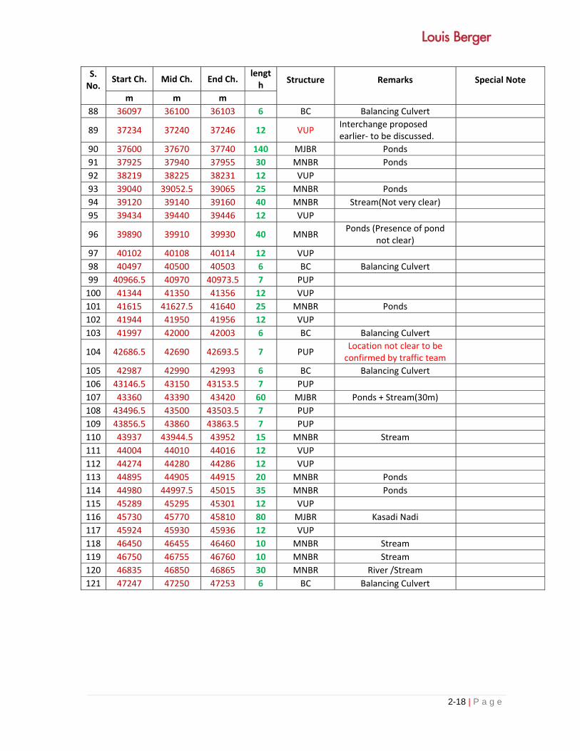
2.9 Proposed list of Structure
Prosed list of structures provided are presented in Table 2.4 bellow:
Table 2.4: Proposed list of Structures
S. No.
Start Ch. Mid Ch. End Ch. length
Structure
Remarks
Special Note
m m m
0 Interchange
1 310 920 1530 1220 MJBR+PUP
Major bridge with pier placement to allow for people movement at ch 808.
2 1630 1725 1820 190 MJBR+VUP
Major bridge with pier placement to allow for Vehicle movement at ch 1745.
Structure at S. no.2 to 20 shall be replaced by two major elevated structure/tunnels between ch 1675 to 7400 after finalsation of structure details in Sanjay gandhi National Park.
3 2777 2780 2783 6 BC Balancing Culvert
4 3098.5 3100 3101.5 3 FOB
5 3454 3460 3466 12 VUP
6 3667 3670 3673 6 BC Balancing Culvert
7 3960 3975 3990 30 MNBR Kaman river tributary
8 4185 4195 4205 20 VUP Existing bridge to be
dismantle
9 4197 4200 4203 6 BC To be planned along with
VUP
10 4747 4750 4753 6 BC Balancing Culvert
11 5190 5220 5250 60 MJBR Ponds
12 5524 5530 5536 12 VUP
13 5957 5960 5963 6 BC Balancing Culvert
14 6056.5 6058 6059.5 3 FOB
15 6170 6173 6176 6 BC Stream, refer below VUP, to be planned with VUP
16 6163 6173 6183 20 VUP existing culvert to be
dismantle
17 6517 6523 6529 12 VUP
18 6920 6970 7020 100 MJBR 20m required but river is braiding at this location
19 7097 7100 7103 6 BC Wet Land
20 7230 7410 7590 360 MJBR Stream U shaped crossing+
wetlands

2-16 | P a g e
S. No.
Start Ch. Mid Ch. End Ch. length
Structure
Remarks
Special Note
m m m
21 7657 7660 7663 6 BC Wet land
22 7730 7975 8220 490 MJBR 7+750: 20m Stream U
shaped crossing+ wetlands
23 8271 8274 8277 6 BC Stream
24 8500 8555 8610 110 MJBR Stream U ‐ turn
25 8642 8645 8648 6 BC Stream
26 8712.5 8806.25 8900 187.5
MJBR Stream + Wetland
27 9165.5 9178 9190.5 25 MNBR Stream
28 9629 9644 9659 25 MNBR Stream
29 9820 9925 10030 210 MJBR 20m required+ stream along road alignment
30 10290 10300 10310 20 MNBR Stream
31 10791 10796 10801 10 MNBR Stream
32 10863 10889.25 10915.5 52.5 VUP+MNBR Stream+ Adjacent Road
33 11290 11570 11850 560 MJBR 25m‐stream along road alignment+wet land
34 12110 12280 12450 340 MJBR+PUP
Stream along road alignment and Road , Road location not very clear (ch 12423)
35 12871.5 12875 12878.5 7 PUP
36 13227 13230 13233 6 BC Stream
37 13400 13490 13580 180 MJBR River
38 14120 14290 14460 340 MJBR River
39 15354 15360 15366 12 VUP
40 15590 15630 15670 80 MJBR River
41 15800 15803 15806 6 BC Stream
42 16410 16490 16570 160 MJBR Stream on road with
backwater effects due to tides
43 16630 16645 16660 30 MNBR Stream
44 17127 17133 17139 12 VUP
45 17530 17625 17720 190 MJBR
30m stream on road with backwater effects due to tides, no crossing‐Stream on road
46 18098 18108 18118 20 MNBR Stream
47 18417.5 18472.75 18528 110.5
MJBR Stream, and its tributary on road alignment,25m‐Skew Stream
48 18810 18875 18940 130 MJBR Skew Stream All these structuresprovided instead of one flyover + bridge proposed
49 19010 19040 19070 60 FVR BMC Pipe Line
50 19230 19335 19440 210 MJBR 20m‐Stream on road
51 19540 19777.5 20015 475 MJBR Skew Stream

2-17 | P a g e
S. No.
Start Ch. Mid Ch. End Ch. length
Structure
Remarks
Special Note
m m m
52 20170 20230 20290 120 MJBR stream along road
alignment + wet land between ch 18798 to 22998 (km 4.2) earlier. 53 20580 20615 20650 70 FVR
54 20730 20735 20740 10 MNBR Stream
55 21067.5 21075 21082.5 15 MNBR Stream
56 21890 22035 22180 290 MJBR+FVR 60m and 20m‐streams(2)+
road
57 22285 22290 22295 10 MNBR Stream
58 22725 22745 22765 40 MNBR 15m‐Stream(backwater of
low water line area)
59 23497 23500 23503 6 BC Balancing Culvert
60 23879.5 23883 23886.5 7 PUP
61 24164 24170 24176 12 VUP
62 24730.5 24734 24737.5 7 PUP
63 24897 24900 24903 6 BC Balancing Culvert
64 25034.5 25038 25041.5 7 PUP To be confirmed by traffic
team
65 25179 25185 25191 12 VUP
66 25572 25575 25578 6 BC Balancing Culvert
67 25756.5 25760 25763.5 7 PUP
68 26045 26048 26051 6 BC Ulhas River backwater
69 26450 26961.5 27473 1023 MJBR+ROB+MNBR
Ulhas River+Railway line
70 27869 27875 27881 12 VUP
71 28245 28248 28251 6 BC Balancing Culvert
72 28589.5 28593 28596.5 7 PUP
73 28836 28851 28866 30 MNBR Ponds
74 29040 29120 29200 160 MJBR Series of Ponds
75 29299.5 29303 29306.5 7 PUP
76 29519 29525 29531 12 VUP
77 29688.5 29692 29695.5 7 PUP
78 29822 29825 29828 6 BC Balancing Culvert
79 30081 31195.5 32310 2229 INTERCHAN
GE
Placement of RE Walls, pier shall be based on presence of streams at the interchange.
80 32560 32640.75 32721.5 161.5
MJBR+PUP Ponds+Road
81 33190 33268 33346 156 MJBR+VUP Ponds + wet land+Road
82 33480 33510 33540 60 MJBR Ponds
83 33625 33712.5 33800 175 MJBR River,Ponds
84 33851.5 33855 33858.5 7 PUP
85 34160 34270 34380 220 MJBR Ponds + wet land
86 34914.5 34918 34921.5 7 PUP
87 35622 35628 35634 12 VUP
2-18 | P a g e
S. No.
Start Ch. Mid Ch. End Ch. length
Structure
Remarks
Special Note
m m m
88 36097 36100 36103 6 BC Balancing Culvert
89 37234 37240 37246 12 VUP Interchange proposed earlier‐ to be discussed.
90 37600 37670 37740 140 MJBR Ponds
91 37925 37940 37955 30 MNBR Ponds
92 38219 38225 38231 12 VUP
93 39040 39052.5 39065 25 MNBR Ponds
94 39120 39140 39160 40 MNBR Stream(Not very clear)
95 39434 39440 39446 12 VUP
96 39890 39910 39930 40 MNBR Ponds (Presence of pond
not clear)
97 40102 40108 40114 12 VUP
98 40497 40500 40503 6 BC Balancing Culvert
99 40966.5 40970 40973.5 7 PUP
100 41344 41350 41356 12 VUP
101 41615 41627.5 41640 25 MNBR Ponds
102 41944 41950 41956 12 VUP
103 41997 42000 42003 6 BC Balancing Culvert
104 42686.5 42690 42693.5 7 PUP Location not clear to be confirmed by traffic team
105 42987 42990 42993 6 BC Balancing Culvert
106 43146.5 43150 43153.5 7 PUP
107 43360 43390 43420 60 MJBR Ponds + Stream(30m)
108 43496.5 43500 43503.5 7 PUP
109 43856.5 43860 43863.5 7 PUP
110 43937 43944.5 43952 15 MNBR Stream
111 44004 44010 44016 12 VUP
112 44274 44280 44286 12 VUP
113 44895 44905 44915 20 MNBR Ponds
114 44980 44997.5 45015 35 MNBR Ponds
115 45289 45295 45301 12 VUP
116 45730 45770 45810 80 MJBR Kasadi Nadi
117 45924 45930 45936 12 VUP
118 46450 46455 46460 10 MNBR Stream
119 46750 46755 46760 10 MNBR Stream
120 46835 46850 46865 30 MNBR River /Stream
121 47247 47250 47253 6 BC Balancing Culvert

2-19 | P a g e
S. No.
Start Ch. Mid Ch. End Ch. length
Structure
Remarks m m m
60145 InterchangeInterchange connecting Panvel-Bypass Road and Mumbai-Pune Expressway
1 58920 62545 66170 7250 FVR
2 66220 66285 66350 130 MJBR Pond + 20.0m stream
3 66440 66455 66470 30 MNBR Pond + 6.0m stream
4 66540 66550 66560 20 MNBR Stream
5 66690 66700 66710 20 MNBR Stream
6 67269 67275 67281 12 VUP
7 67505 67520 67535 30 MNBR Ponds + 6.0m stream
8 67720 67730 67740 20 MNBR Stream
9 68390 68400 68410 20 MNBR Stream
10 68418 68424 68430 12 VUP
11 68695 68700 68705 10 MNBR Stream
12 68790 68862.5 68935 145 MNBR Ponds +10.0m stream
13 69030 69045 69060 30 MNBR Stream
14 69200 69590 69980 780 TN
15 70044 70050 70056 12 VUP
16 70055 70060 70065 10 MNBR Stream
17 70140 70200 70260 120 MJBR Stream + Ponds
18 70620 70630 70640 20 MNBR Ponds
19 70790 70825 70860 70 MJBR Stream
20 70920 70955 70990 70 MJBR Ponds
21 71070 71130 71190 120 MJBR Ponds + 40.0m stream
22 71650 71700 71750 100 MJBR Ponds
23 71772 71778 71784 12 VUP
24 72090 72150 72210 120 MJBR Stream
25 72220 72285 72350 130 MJBR Stream
26 73257.5 73270 73282.5 25 MNBR Stream
27 73564 73570 73576 12 VUP
28 73705 73710 73715 10 MNBR Stream
29 73969 73975 73981 12 VUP
30 74120 74130 74140 20 MNBR Stream
31 74150 74205 74260 110 MJBR Nala
32 74492.5 74500 74507.5 15 MNBR Stream
33 74890 74900 74910 20 MNBR Skew Stream
34 75140 75905 76670 1530 TN
35 76840 77420 78000 1160 FVR
36 78809 78815 78821 7 PUP
37 79014 79020 79026 12 VUP
38 79122 79125 79128 6 BC
39 79410 79635 79860 450 MRB
40 79950 79970 79990 40 MNBR Ponds

2-20 | P a g e
DESCRIPTION OF MITIGATION MEASURES INCORPORATED INTO THE PROJECT TO
MEET ENVIRONMENTAL STANDARDS
To make the project environmentally sound and sustainable following mitigation measures have
been considered which are described in mitigation and EMP sections:
Avoidance (assess to avoid the negative impact wherever possible)
Minimization (assess to minimize the associated negative impact)
Compensation (compensate the negative impact associated with the project activity if,
avoidance and minimization is not possible for the associated impact)
2.10 MATERIAL SOURCES:
Figure 2.4 location Chart Showing Various Material Sources 2.10.1 Cement, Steel & Bitumen
Cement, steel and bitumen etc are the manufactured materials. Bitumen is produced indigenously in India and is generally supplied from the nearest oil refinery. Regular supply of bitumen can be satisfactorily met by advance agreements.
The reinforcement steel both CRS and ordinary Tor steel of different grades conforming to BIS specifications is available and can be procured directly from mills. Hence there is no difficulty in respect of its availability in this project.
Cement conforming to BIS specifications can be procured directly from factories or can be purchased from dealers of the factories in all the major towns near the project road.

2-21 | P a g e
Figure 2.4: Location Chart Showing Various Material Sources
2.11 STATUTORY CLEARANCE FOR BORROW AREA AND STONE QUARRY
The quarry material will be obtained from licensed sites only, which operate with proper environmental clearances, including clearances under the Air Act. If Contractor wants to open a new Quarry he shall take the

2-22 | P a g e
entire requisite licenses from concerned Govt. Departments
2.12 RAINWATER HARVESTING
Ground water recharging / rain water harvesting structures shall be provided at every 500 m interval on either side of pavement and one each in every loop of clover leaf/dumble interchange as well as suitable number of such units on either side of the vehicular underpasses wherever the profile of the cross road has been lowered, shall also be provided to take care of drainage and prevent flooding


i | P a g e
TABLE OF CONTENTS
CHAPTER - 3: DESCRIPTION OF THE ENVIRONMENT ..................................................................... 3-1
3.1 METHODOLOGY ADOPTED FOR ENVIRONMENTAL IMPACT ASSESSMENT ............................ 3-1
3.2 MACRO LEVEL BASELINE ............................................................................................................ 3-3
3.2.1 Physical Environment ..................................................................................................... 3-3
3.2.2 Physical Setting .............................................................................................................. 3-6
3.2.3 Geology and Seismicity .................................................................................................. 3-7
3.2.4 Soil .................................................................................................................................. 3-8
3.2.5 Water Resources ............................................................................................................ 3-9
3.2.6 Ecological Resources ................................................................................................... 3-10
3.3 MICRO LEVEL BASELINE ........................................................................................................... 3-11
3.3.1 Air Quality ..................................................................................................................... 3-11
3.3.2 Noise Level ................................................................................................................... 3-12
3.3.3 Water Resources and Quality ....................................................................................... 3-14
3.3.4 Ecological Resources ................................................................................................... 3-22
3.3.5 Costal Regulation Zone Areas: ..................................................................................... 3-26
3.4 AVAILABILITY OF CONSTRUCTION MATERIAL ......................................................................... 3-32
3.5 SOCIAL ENVIRONMENT ............................................................................................................. 3-33
3.5.1 Archaeological and Cultural Properties ......................................................................... 3-33
3.5.2 Settlements and Properties ........................................................................................... 3-34
3.6 OTHER FEATURES OF PROJECT AREA OF INFLUENCE (PIA) ................................................ 3-35
3.6.1 Industries ...................................................................................................................... 3-35
3.6.2 Educational Institutes .................................................................................................... 3-36
3.6.3 Land Use Pattern .......................................................................................................... 3-36
LIST OF TABLES
Table 3.1: Monthly Rainfall (from 2009 to 2013) of the project district Thane and Raigad ............... 3-3
Table 3.2: Soil Characteristic of the Project area ................................................................................ 3-8
Table 3.3: Project District Wise Forest Area ...................................................................................... 3-10
Table: 3.4 AAQ monitoring result along the MMC project ................................................................ 3-12
Table 3.5: National Ambient Air Quality Standards ........................................................................... 3-12
Table 3.6: Noise level along the MMC ............................................................................................... 3-13
Table 3.7: Ambient Noise Quality Standards ..................................................................................... 3-13
Table 3.8: List of Surface water Bodies Crossed the Project MMC: Stream and Rivers ................ 3-14
Table 3.9: Ponds and Low land along the Project Road .................................................................. 3-15

ii | P a g e
Table 3.10: Surface Water Quality along the Project Road .............................................................. 3-15
Table 3.11: Ground Water Quality along the Project Road .............................................................. 3-18
Table 3.12: List of trees along the Project Road ............................................................................... 3-22
Table 3.13: Project MMC alignment in Forest Areas .............................. Error! Bookmark not defined.
Table 3.14: Project Alignment in CRZ area as per CRZ notification 2011 ....................................... 3-28
Table 3.15: Project Alignment in CRZ area as per CRZ notification 1991 ....................................... 3-30
Table 3.16: Construction Material ...................................................................................................... 3-33
Table 3.17: List of religious properties along the project .................................................................. 3-33
Table3.18: List of village along the MCC project ............................................................................... 3-34
LIST OF FIGURES
Fig-3.1: Seismic Zoning Map of India ..................................................................................................... 3-8
Fig. 3.2: Forest area (sq.km) of the Project District ............................................................................... 3-10
Fig. 3.3: Ponds and stream along the Project Road ............................................................................ 3-17
Fig. 3.4. Water Supply Pipelines crosses by the proposed MMC alignment ......................................... 3-21
Fig.3.5: View of SGNP in project area ................................................................................................. 3-24
Fig.3.6 View of Tungareshwar Wildlife sanctuary ................................................................................. 3-25
Fig 3.7: Matheran Eco Sensitive Zone .................................................................................................. 3-26
Fig.3.8: Religious Properties along the Project Road ........................................................................... 3-34
Fig.3.9: Critically Notified Areas on google image ................................................................................ 3-35
Fig.3.10: Land use of the Project Area ................................................................................................. 3-36

3-1 | P a g e
CHAPTER - 3: DESCRIPTION OF THE ENVIRONMENT
As a precursor for the prediction of various types of environmental impacts likely to arise due to
the implementation of this project, it is essential to establish the baseline environmental status of
the physical, natural and socio cultural environment parameters along the project alignment and
within corridor of influence. This chapter presents the existing baseline status of the project
influence area. The data has been collected from various secondary sources and the field survey
within Proposed ROW and within the CoI i.e. 10 km on either side from the centerline of the
Project alignment (MMC) by the environmental team. The baseline data has been presented at
the Macro and the Micro level in the succeeding paragraphs. The Macro level baseline
represents data within 10km on either side of road and Micro level represents description of
baseline in the direct influence area of the project corridor i.e. within the proposed Right of Way
(45 to 99m).
This chapter is constituted into two parts viz. brief methodology is presented in first part and
baseline conditions are presented in second part of the chapter.
3.1 METHODOLOGY ADOPTED FOR ENVIRONMENTAL IMPACT ASSESSMENT
The following steps are involved in EIA methodology:
Assembly, Literature Survey and Analysis of Data
Assembly, Literature Survey and Analysis of Data Published and other recorded data e.g. on
wildlife, flora, climate, pollution etc. pertaining to the project were studied and reviewed. TOR and
MOEF guidelines were also reviewed prior to carry out EIA studies.
Incorporation of Environmental considerations into the Feasibility study
Scoping process was used to determine the anticipated range of issues to be addressed and an
in-depth study required for environmental analysis during project Design, Construction and
Operational phases. Potential impacts due to implementation of Multi Model Corridor (navghar to
Chirner) baseline data were determined by conducting physical visit to the project site and
environmental screening. The aim was to address adequately the potential impacts into the
design so as to minimize the negative impacts.
Reconnaissance Surveys
Reconnaissance Surveys were undertaken by all members of the study teams initiating with a
joint reconnaissance with the members of the MMRDA, and those responsible for the
documentation of the environmental investigations and its analysis.
Environmental Screening
The objective behind the environmental screening was to delineate affected environmental
features / issues e.g. waterways, forest areas, CRZ, mangroves, plantations / trees, cultural
heritage, market places / human settlements, agricultural land, air, water, natural resources,
noise etc. in the project area, in order to define impacts and to minimize the adverse
environmental impacts by suggesting best engineering solutions / options at optimal costs and

3-2 | P a g e
further to categorize and define the scope of Environmental Impact Assessment (EIA) study to be
conducted.
Documentation of Baseline Conditions
The area of influence of the project was defined considering MoEF requirements (EIA
notification, 14th Sep 2006 and Dec 2009) and other statutory requirements. Baseline conditions
within the defined area were documented. As per MoEF guidelines for conducting EIA; the
geographical scope of the EIA study will be of 10 km radius for highway/expressway projects.
However realistically speaking, as the project relates to implementation of new alignment in
green field area, the direct influence of the project is restricted to Right of Way (ROW) only.
Therefore the baseline status has been documented at the ROW level. However, major
environmental features like wildlife sanctuary, national parks, eco-sensitive zone, and industrial
areas were recorded within 10 km radius of the project corridor.
Assessment of Potential Impacts
Potential significant impacts were identified on the basis of analytical review of baseline data,
land uses, environmental factors, socio-economic conditions and review of assessment of
potential impacts identified in previous similar kind of projects.
Integration of Environmental Assessments in the Design Process:
The design and decision-making process, integrated environmental and resettlement and
rehabilitation issues and prompted the early identification of appropriate actions. Such actions
included, for example, shifts in alignments; based on awareness of the locations of cultural
resources, and biological resources such as significant areas along the project road like trees,
water resources, temples etc. to reduce local impacts.
Assessment of Alternatives
Alternatives were continuously assessed throughout the process. A more formal assessment
was also undertaken as a part of the environmental assessment process including the
assessment of the “No Action” Alternative as is customarily included as a part of the formal
assessment methodologies to ensure that it has been given proper consideration.
Identified Mitigation & Environmental Enhancement Measures
Positive actions not only to avoid adverse impacts, but to capitalize on opportunities to correct
environmental degradation or improve environmental conditions were determined.
Community Consultations
Consultations with concerned officials, agencies and potentially affected persons continued
through the process and will continue as the project proceeds. The issues raised by the
community and the various stakeholders were incorporated in the design and
construction/operation plan of the project.
Preparation of the Environmental Management Plan (EMP)
An EMP will be prepared to specify the steps necessary to ensure that the necessary measures
have been and will be taken. This includes the monitoring plan and gives details of the resources

3-3 | P a g e
budgeted and the implementation arrangements.
3.2 MACRO LEVEL BASELINE
3.2.1 Physical Environment
Meteorology
Project road is passing through Palghar, Thane and Raigad Districts in the state of Maharashtra.
Regional meteorological conditions and the project corridor is of high significance in MMC
development projects because transportation and diffusion of all ambient air pollutants generated
during project implementation and/or operational phase once they are air borne are governed by
local meteorological conditions.
The data is used for measuring the capacity of dispersion and diffusion of pollutants during the
construction and operation stages of project. This data also plays a vital role in locating hot mix
plants/ Batch Mix Plant to offset any impact on sensitive receptors. The meteorological data also
helps in prediction using different models.
Climate
A hot and humid summer characterizes the climate of the area, except during the southwest
monsoon season when it is raining very heavily. The year may be divided into four seasons. The
cold season, December to February (not less than 18 degree) is followed by the hot season from
March to about the middle of June. The period from the middle of June to September is the
south-west monsoon season. October and November form the post monsoon or transition
period.
Rainfall
The area receives maximum rainfall during south-west monsoon period i.e. June to September.
About 90 % of the annual rainfall falls during monsoon season. Only 10 % of the annual rainfall
takes place between Octobers to May period. Thus, surplus water for ground water recharge is
available only during the southwest monsoon. The rain fall of the project district is presented in
Table 3.1
Table 3.1: Monthly Rainfall (from 2009 to 2013) of the project district Thane and Raigad

3-4 | P a g e
District Thane
Year
Month
Jan Feb March April May June
R/F %DEP R/F %DEP R/F %DEP R/F %DEP R/F %DEP R/F %DEP
2009 0 -100 0 -100 0 -100 0 -100 0 -100 131.1 -70
2010 0 -100 0 -100 1.4 367 0 -100 0 -100 380.4 -13
2011 0 -100 0 -100 0 -100 0 -100 0 -100 372.4 -15
2012 0 -100 0 -100 0 -100 0 -100 0 -100 241 -45
2013 0
-100 0 -100 0 -100 0 -100 12.5 -10 911.2 109
Year July August Sept Oct Nov Dec
R/F %DEP R/F %DEP R/F %DEP R/F %DEP R/F %DEP R/F %DEP
2009 1290
.5 30 176.2 -73 203.2 -40
189.2
146 62.9 253 0 -100
2010 1007
.2 2 851.1 32 426.1 27
94.3
23 80.2 351 0 -100
2011 1132
.9 16 935.1 38 377.7 11
62.8
-26 0 -100 0 -100
2012 725.
7 -25 544.4 -20 577.3 70
104.5
24 0 -100 0 -100
2013 1157
.7 19 483.6 -29 357.6 5
103.8
23 0.1 -99 0 -100
District Raigad
Year Jan Feb March April May June
R/F %DEP R/F %DEP R/F %DEP R/F %DEP R/F %DEP R/F %DEP
2009 0 -100 0 -100 0 -100 0 -100 0.1 -100 205.4 -68
2010 0 -100 0 -100 0 -100 0.5 -81 0 -100 508.3 -21
2011 0 -100 0 -100 0 -100 0 -100 0.3 -99 768.4 17
2012 0 -100 0 -100 0 -100 0 -100 0 -100 441.8 -33
2013 0 -100 0 -100 0 -100 0 -100 0.3 -99 1177.7 79
Year
Month
July August Sept Oct Nov Dec
R/F %DEP R/F %DEP R/F %DEP R/F %DEP R/F %DEP R/F %DEP
2009 1185
.3 -4 287.5 -67 349.3 -14
228.9
121 203.3 780 0 -100
2010 1372
.6 11 946 8 520.2 28 131 26 95.9 315 0 -100
2011 1504
.5 24 1085.4 27 549.1 38
162.5
42 0 -100 0 -100
2012 937.
8 -22 898.1 5 618.7 55
174.9
53 0 -100 0 -100
2013 1712 42 457.8 -46 332.7 -16 112.7
-2 3 -85 6.5 51

3-5 | P a g e
Source: http://hydro.imd.gov.in/hydrometweb/(S(hwn0mafuqekjiz2vadqtcja4))/DistrictRaifall.aspx
Palghar district created in 1 August 2014.
Temperature
There are two meteorological observatories in the district Raigad at Alibag and Bhira for which
long period data is available. The data for the stations Alibag and Bhira may be taken as
representative of the conditions in the district generally. Being a coastal district, the diurnal and
seasonal variations of temperature at Alibag are not large. At Alibag on the coast, May is the
hottest month, with the mean daily maximum temperature at 32.3°C and the mean daily minimum
temperature at 26.4°C. At Bhira, eastward of the district, April is the hottest month with the mean
daily maximum temperature at 39.9°C and the mean daily minimum temperature at 22.2°C.
Fresh breezes from the sea relieve the oppressive heat particularly in the coastal regions in the
afternoons. The onset of the southwest monsoon early in June brings down the temperatures in
the interior part of the district. After the withdrawal of the southwest monsoon by the end of
September, the day temperatures increase slightly and the weather in October and November is
almost as in the summer months near coast. In interior towards east, mean daily maximum
temperatures in October and November are 5-6°C less than in the summer months. In the period
December to February the weather is cooler than in the post monsoon months.
The highest maximum temperature ever recorded at Alibag was 40.0°C on 19th April, 1955 and
on 12th March, 1985 and the lowest minimum temperature ever recorded was 9.4°C on 13th
January 1934. The highest maximum temperature ever recorded at Bhira was 45.5°C on 28th
April, 1995 and the lowest minimum temperature ever recorded was 6.3°C on 28th January
1973.
There is a meteorological observatory in the district Thane at Dahanu. The records of this
observatory may be taken as fairly representative of the meteorological conditions in the district.
But in the interior parts of the district, temperatures are likely to be slightly lower in the cold
season and higher in the hot season than at Dahanu. Being a coastal district the variation of
temperature during the day and the seasons is not large. After February, temperatures
progressively increase till May, which is the hottest month with the mean daily maximum
temperature at 33.4°C and mean daily minimum temperature at 26.8°C. In the summer season
and in June before the onset of the monsoon day temperatures may sometime go above 37°C in
the coastal parts while in the interior it may be a couple of degrees higher. The oppressive heat
is on most days relieved by cool sea breezes particularly in the coastal regions. The afternoon
thundershowers on some days during the hot season also bring welcome relief. With the onset of
the southwest monsoon by about the first or second week of June the temperatures decrease a
little. From about the beginning of October, when the southwest monsoon withdraws day
temperatures increase and in October and November days are nearly as hot as in the summer,
while nights become progressively cooler. After November temperatures decrease and in
January, which is the coldest month, the mean daily maximum temperature is 27.5°C and the
mean daily minimum temperature is 16.5°C. In the cold season, cold waves sometimes affect the
district when the night temperatures may go down to less than 10°C. The highest maximum

3-6 | P a g e
temperature ever recorded at Dahanu was 40.6°C on 19th April 1955 and the lowest minimum
temperature ever recorded was 8.3°C on 8th January1945.
Humidity
The air is humid throughout the year. Relative humidity is on an average 86% during the
southwest monsoon season. In the rest of the year the relative humidity is between 64 and 75%
in coastal regions. In interior parts the humidity is about 40% in summer.
The nature and Characteristics of pollutants varies with change in the humidity in the
atmosphere. Fog provides possibility for suspended particles to coalesce and also enhances
chemical reaction of the gaseous pollutants.
Cloudiness
During the southwest monsoon season the sky is heavily clouded to overcast. In the rest of the
year sky is mostly clear or lightly clouded.
Wind
Wind speed and wind directions have a significant role on dispersion of atmospheric pollutants
and therefore, the ambient air quality of the area. Ground level concentrations for the pollutants
are inversely proportional to the wind speed in the downwind direction, while in upwind direction
no effect is observed and in crosswind directions partial effect due to emission sources is
observed.
In Raigad district Winds are very strong and blow from southwest or west during the monsoon
season. During the period October to March, winds are moderate and blow from directions
between northeast and east in the mornings and from northwest in the afternoons. In April-May
there is strengthening in wind and it blows mostly from northwest.
In Thane district Winds are generally strong except in winter and post monsoon season when
they are moderate. During the southwest monsoon season, the wind speed is maximum. Winds
during May and the monsoon months are mainly from directions between southwest and west. In
the rest of the year winds blow from directions between east and southeast in the mornings.
While in the afternoon wind blows from directions between north and northwest in winter and
from west and northwest in the summer season.
3.2.2 Physical Setting
Project alignment (MMC) is passing through plain terrain, in few location alignment is
crossing through low lying areas and foot hills and hill crossing in Tahne and Raida District.
The Project road is take off from NH-8 at km 490.100 near Navghar(Thane) and end at
Chirner in plain agriculture land. It crosses major roads, rivers, streams, costal area, water
supply pipelines, ponds, railway lines, forest, national Parks, wildlife Sanctuary and built-up
areas. Proposed MMC is new alignment which will have single corridor in which multiple
modes, such as buses, BRT, metro rail and cars, along with utilities such as water, sewage
and gas lines are present in the same Right of Way. The total length of the multi model
corridor project is approximately 80 Km.

3-7 | P a g e
Topography
The topography of the project area is plain terrain, in few location alignment is crossing through
low lying areas and foot hills and rolling terain, built-up areas, railways lines, rivers, streams,
CRZ, forest, national Parks, wildlife Sanctuary etc.
3.2.3 Geology and Seismicity
3.2.3.1 Geological Description
The area of the MMC has been classified as volcanic rocks and minor basic intrusions. The
general area of the project consists mostly of nearly horizontal dispersed lava flows of Deccan
Trap Basaltic Formation of Mesozoic Era. The thickness of the Igneous Bedrock in the area is
anticipated to be more than 1500m. The Igneous rocks are generally of horizontal deposition.
However, the inclination of the rock layers near the Mumbai region range between 5 degrees to
15 degrees with the horizontal.
Layers of volcanic Breccia formed by sub-aqueous volcanic eruptions through fissures in the
basalt bedrock are often encountered in the area. The thickness of the Breccia rock is typically
less than 50m.
3.2.3.2 Seismology
Project road is fall under seismic zone-III as per the seismic zone map of India (see Fig. 3.1 )

3-8 | P a g e
Fig-3.1: Seismic Zoning Map of India
3.2.4 Soil
Most of the plain area contains Deccan trap which is made of Basaltic lava. Alluvial, Lateritic,
Lametas and Archean soil is found in small patches. Brown/black forest soil is generally found
which changes from place to place depending upon the specific site. The soils in the project area
are generally of three types Viz., black cotton soil, sandy loam soil and clayey loam soils. Soils
are generally sandy loam to muramy which contain boulder and small stones. Black cotton soil is
found at comparatively lower places along the road. Alluvial soil is also found along the road.
To understand the soil quality in the area, 6 locations were selected for soil sampling. Composite
sampling of soil up to root depth (10-15 cm) was carried out at each location.
The important properties of soil are pH, conductivity, SAR, Ca++, Mg++, Sodium, Potassium,
Total Phosphorus, Nitrogen, and moisture content results of soil analysis are given in Table 3.2
Table 3.2: Soil Characteristic of the Project area
Sr. No. Parameter Juchanda Thane Taloja Panvel Uran Chirner
2 Conductivity 1670 360 410 1200 1624 270
3 SAR 1.25 1.16 1.08 1.52 1.19 1.31

3-9 | P a g e
4 Ca 0.57 0.88 0.8 0.72 0.88 1.23
5 Mg 0.05 0.18 0.19 0.16 0.2 0.29
6 Sodium 0.7 0.85 0.76 1.01 0.88 1.15
7 Potassium 0.11 0.27 0.19 0.25 0.2 0.18
8 Total
Phosphorus% 0.28 0.14 0.16 0.18 0.2 0.18
9 Total
Nitrogen 0.09 0.07 0.04 0.06 0.04 0.07
10 Moisture Content
5.8 4.9 6.1 3.4 2.43 2.83
3.2.5 Water Resources
Hydrogeology
Hydrogeology is concerned primarily with the mode of occurrence, movement and distribution of
water occurring in the sub surface in relation to the geological environment. The occurrence and
movement of water in the subsurface is broadly governed by geological framework that is nature
of rock formation including their porosity (primary and secondary) and permeability.
Deccan Trap Basalt of upper Cretaceous to lower Eocene is the major rock formation and
intruded by a number of dykes. The western part of the district consisting Basalt flows are altered
to Laterite. Recent deposits comprising Beach Sand and Alluvium occur along the coast and in
the river mouth, however they do not form potential aquifer.
Ground water in Deccan Trap Basalt occurs mostly in the upper weathered and fractured parts
down to 10 – 15 m bgl under unconfined condition. The water bearing strata at deeper depth
exists under semi confined to confined conditions. The dug wells in these areas show rapid
decline in water level during post monsoon period and practically go dry in peak summer. In foot
hill zones the water table is relatively shallower near water course. The yield of dug wells tapping
upper phreatic aquifer ranges between 45 to 60 m3/day, whereas that of bore wells varies from
0.50 to > 20 m3/hr. depending upon the local hydrogeological conditions, however in most of the
bore wells it is up to 5 m3/hr.
Ground water Levels
Ground water accumulation was monitored in boreholes during and after completion of drilling
operations. Groundwater was encountered at depths between 0.50m and 3.80m below ground
surface, in the boreholes. Seasonal and annual fluctuations in water/ground water levels can be
expected to occur.
Regional Drainage
Drainage of Project area is part of Ulhas Drainage System. The discharge of drainage flows
through general slope of the land to Ulhas River and its tributaries.
The main hydrological features along the proposed project MMC are the small streams, ponds
and Ulhās River. The drainage system of the project area consists of various small streams,
creeks and rivers and their tributaries which receive water back water during high tides and rain

3-10 | P a g e
waters. The River Ulhas is major rivers in the project area. Project alignment (MMC) crosses
Ulhas River, Creeks and numerous small streams.
There are many discarded mining quarry area located in the project corridor which receive water
during rainfall and act as water harvesting. Ditch, low lands also noted in the project areas.
Some of them will be partially affected by the proposed alignment of the project.
3.2.6 Ecological Resources
The State of Maharashtra with geographical area of 3,07,713 sq km is having 61,939 sq km as
forest area, out of which 51549sq.km is reserve forest, 6727sq.km protected forest and
3082sq.km unclassed forests. Out of this project district Thane and Raigad cover 5629.33 sq.m
of the total forest area. Description of forest area is presented in Table 3.3 and Fig. 3.2
Table 3.3: Project District Wise Forest Area
District Forest (Area in sq.m)
Reserve Forest Protected Forest Unclassed Forest Total
Thane 2880.54 988.52 11.95 3881.01
Raigad 1407.38 171.24 169.7 1748.32
Total 4287.92 1159.76 181.65 5629.33
Source:http://www.indiaenvironmentportal.org.in/files/file/maharashtra%20forest%20statistics%202013.pdf
Fig. 3.2: Forest area (sq.km) of the Project District
3.2.5.1 Environmentally Sensitive Zones/ Hot Spots
The State has 6 National Parks,47 Wildlife Sanctuaries and 4 Conservation Reserves(Total 57
Protected Areas) with a total of 10,057.013 sq km area, amounting to 3.26% of the State’s
geographical area. There are 29 Ramsar sites in India and none of them are located in the
Maharashtra state.

3-11 | P a g e
3.3 MICRO LEVEL BASELINE
3.3.1 Air Quality
The air quality of the project alignment is influenced by emissions from stationary sources like
domestic sources from various settlements, industries and stone crushers operating in the
project areas and from mobile sources like the vehicles plying along the existing road and
construction activities. All these sources contribute to the local air pollution levels.
In order to establish the baseline air pollution status, ambient air quality were monitored at the
various locations along the project alignment. Table 3.4 provides air quality monitoring results
with respect to each location where air quality has been monitored.
Respirable dust samplers/high volume samplers of Envirotech Instruments were used for
monitoring particulate matter size 10 micron (PM10), respirable particulate matters size 2.5
(PM2.5), SO2, and NOx. M/s. International Testing Centre, Panchkula, Haryana were contracted,
which is an approved Laboratory by Ministry of Environment and Forest, GOI for collection and
analysis of air samples.
Samples were collected from seven locations namely at, km0.000 of project alignment, km6.000
of project alignment, Near chinkot -Anjur-Phata road, km32.000 of project alignment, crossing of
pipeline of alignment, km43.000 of project alignment, Matheran Eco sensitive zone, km56.000 of
project alignment, Matheran Eco sensitive area, km56.000 of project alignment, km 78.550
of project (in village road of Belandkhar village)along the proposed alignmeny of MMC project
alignment. These air quality monitoring stations were selected depending on the factors like land
use so that samples are true representatives of the project site. The samples were analyzed for
pollutants of interest (PM10 , PM2.5, SO2, NOx, CO) using the appropriate method prescribed by
Bureau of Indian Standards and Central Pollution Control Board.
All along the project road the level of PM10 level recorded higher than the prescribed permissible
limit due to higher traffic movement, earth work for construction and agriculture land use along
the project alignment. Remaining parameters are well within the permissible limits. The
Monitoring locations photos are pasted at the end of the chapter.

3-12 | P a g e
Table: 3.4 AAQ monitoring result along the MMC project
Sl.
No
.
Pa
ram
ete
r
Un
its
of
Me
asu
rem
ents
AAQ Monitoring location of MMC project
Pre
sc
rib
ed
Lim
its
Pro
toc
ol
km
0.0
00
of
pro
jec
t ro
ad
km
6.0
00
of
pro
jec
t ro
ad
, N
ear
ch
ink
ot
-An
jur-
Ph
ata
ro
ad
km3
2.0
00
of
pro
jec
t ro
ad
, cr
os
sin
g o
f p
ipel
ine
ro
ad
km4
3.0
00
of
pro
jec
t ro
ad,
Mat
her
an
Ec
o
sen
sit
ive
zon
e
km5
6.0
00
of
pro
jec
t ro
ad,
Mat
her
an
Ec
o
sen
siti
ve
are
a
Km
61.5
00
of
pro
ject
ro
ad
, cr
oss
ing
of
NH
-4
km
78
.55
0 o
f p
roje
ct
( o
n
vill
age
roa
d o
f B
ela
nd
kh
ar v
illa
ge)
Date of AAQ Monitoring 14.1.2015 14.1.201
5 17.1.2015 16.1.2015 16.1.15 15.12015 15.1.2015
1 PM10 gm �� 83 85 84 86 89 86 100 IS: 5182 (Part 23), 2006
2 PM2.5 gm �� 45 47 46 49 51 46 60 CPCB Guidelines
3 SO2 gm �� 26 28 27 27 29 27 80 IS: 5182 Part-II, 2001
4 NOx gm �� 28 31 28 30 34 32 80 IS: 5182 Part-VI, 2007
5 CO mgm 1.6 1.4 1.5 1.7 1.8 1.8 1.7 4 IS: 5182 Part- 10
National Ambient Air Quality Standards (NAAQS)
The permissible air quality standards for particulate and gaseous pollutants are presented in
Table 3.5 as laid down by the CPCB.
Table 3.5: National Ambient Air Quality Standards
Sl. No.
Parameter Units of
Measurements
Prescribed limits (Industrial/Residential, Rural and other area)
Prescribed limits (Ecologically Sensitive Area notified by Central
Govt.))
1 PM-2.5 g/m3 60 60
2 PM-10 g/m3 100 100
3 SO2 g/m3 80 80
4 NOx g/m3 80 80
5 CO mg/m3 4 4
Source: NAAQ standard MOEF, Gadget Notification B 29016/20/90PCI- I, dtd.18 Nov.2009
3.3.2 Noise Level
The existing noise environment were monitored at seven locations by ITC Consultant,
Panchkula. Result of existing noise level along the alignment is presented in the Table 3.6.The
data of monitored Noise levels revealed that the noise levels are within the permissible at all
location except at Starting point of MMC due to high traffic movement on NH-8 (Mumbai
Ahmedabad Road) and Dhaba located near the monitoring station. The Ambient Noise Quality
standard is presented in Table 3.7. The Monitoring locations photos are pasted at the end of the
chapter.

3-13 | P a g e
Table 3.6: Noise level along the MMC
Sl. No.
Name of Locations Date of
Monitoring Category of
the Area
Leq dB(A),
Day
Leq dB(A), Night
1 km0.000 of project road 15.1.2015 Residential 75.8 69.9
2
km6.000 of project road, Near chinkot -Anjur-Phata road, In between Tungreshwar WLS and SGNP
15.1.2015 Eco sensitive
Zone 45.2 44.1
3 km32.000 of project road, crossing of pipeline road, Kolegaon
18.1.2015 Residential 74.7 56.1
4 km43.000 of project road, Matheran Eco sensitive zone
17.1.2015 Residential 56.7 40.8
5 km56.000 of project road,
Matheran Eco sensitive area 17.1.2015 SILENCE ZONE 53.0 45.4
6 Km 61.500 Kone Village 16.1.2015 Residential 80.3 74.4
7 km 78.550 of project ( on village road of Belandkhar village)
16.1.2015 Residential 65.0 40.7
Table 3.7: Ambient Noise Quality Standards
Area Code Category of Area Noise dB(A) Leq
Daytime* Night time*
A Industrial Area 75 70
B Commercial Area 65 55
C Residential Area 55 45
D Silence Zone 50 40
Note: 1. Day time shall be reckoned from 6.00 a.m. and 10.00 p.m.
2. Night time shall be reckoned from 10.00 p.m. to 6.00 p.m.
3. Silence zone is defined as an area comprising not less than 100 metres around
hospitals, educational institutions and courts. The silence zones are zones which are
declared as such by the competent authority.
4. Mixed categories of areas may be declared as one of the four above mentioned
categories by the competent authority.
*dB(A) Leq denotes the time weighted average of the level of sound in decibels on scale
A which is relatable to human hearing.
A "decibel" is a unit in which noise is measured.
"A", in dB(A) Leq, denotes the frequency weighting in the measurement of noise and
corresponds to frequency response characteristics of the human ear.
Leq : It is an energy mean of the noise level, over a specified period.
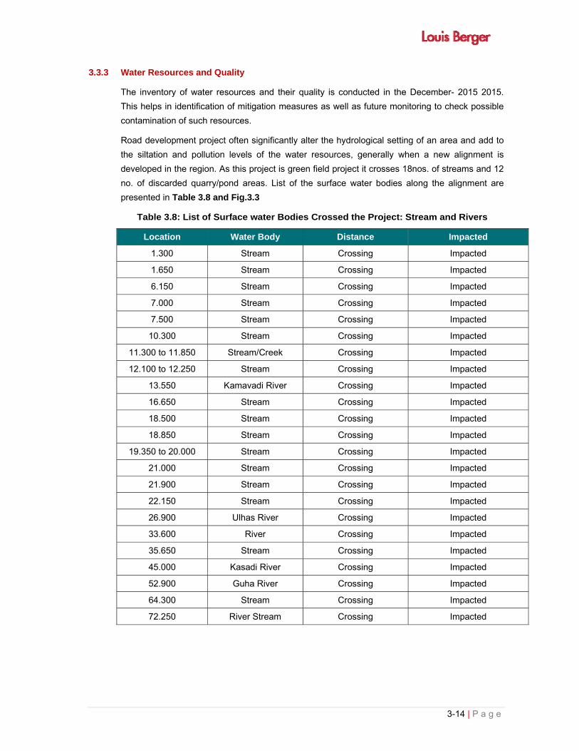
3-14 | P a g e
3.3.3 Water Resources and Quality
The inventory of water resources and their quality is conducted in the December- 2015 2015.
This helps in identification of mitigation measures as well as future monitoring to check possible
contamination of such resources.
Road development project often significantly alter the hydrological setting of an area and add to
the siltation and pollution levels of the water resources, generally when a new alignment is
developed in the region. As this project is green field project it crosses 18nos. of streams and 12
no. of discarded quarry/pond areas. List of the surface water bodies along the alignment are
presented in Table 3.8 and Fig.3.3
Table 3.8: List of Surface water Bodies Crossed the Project: Stream and Rivers
Location Water Body Distance Impacted
1.300 Stream Crossing Impacted
1.650 Stream Crossing Impacted
6.150 Stream Crossing Impacted
7.000 Stream Crossing Impacted
7.500 Stream Crossing Impacted
10.300 Stream Crossing Impacted
11.300 to 11.850 Stream/Creek Crossing Impacted
12.100 to 12.250 Stream Crossing Impacted
13.550 Kamavadi River Crossing Impacted
16.650 Stream Crossing Impacted
18.500 Stream Crossing Impacted
18.850 Stream Crossing Impacted
19.350 to 20.000 Stream Crossing Impacted
21.000 Stream Crossing Impacted
21.900 Stream Crossing Impacted
22.150 Stream Crossing Impacted
26.900 Ulhas River Crossing Impacted
33.600 River Crossing Impacted
35.650 Stream Crossing Impacted
45.000 Kasadi River Crossing Impacted
52.900 Guha River Crossing Impacted
64.300 Stream Crossing Impacted
72.250 River Stream Crossing Impacted

3-15 | P a g e
List of Ponds located along the Project Road is presented in Table: 3.9 and Fig 3.4
Table 3.9: Ponds and Low land along the Project Road
Location at proposed Chaiange of MMC
Water Body Distance Impacted
0.300 Low land Crossing Impacted
3.850 Pond 25m Not Impacted
28.700 Pond (low land) 20m Not Impacted
32.250 Pond/ Discarded
quarry area Crossing Impacted
32.600 Pond/ Discarded quarry area
Crossing Impacted
32.700 Pond/ Discarded quarry area
Crossing Impacted
33.250 Pond/ Discarded quarry area
Crossing Impacted
33.800 Pond/ Discarded quarry area
Crossing Impacted
34.250 Pond/ Discarded quarry area
Crossing Impacted
43.400 Pond/ Discarded quarry area
Crossing Impacted
49.250 Pond/ Discarded quarry area
Partially Impacted Impacted
58.450 Pond/ Discarded quarry area
Crossing Impacted
66.300 Pond/ Discarded quarry area
Crossing Impacted
Only one well is located within the ROW of the MMC project alignment which will be impacted
due to implementation of project. Within the ROW of the proposed MMC - 12 pond like water
bodies (refer Table 3.) will be impacted. This water body comes in existence after the result of
digging/quarry in the areas. Most of the year these ditch/ponds are dry but in the rainy season
they receives the water from their catchment areas and act as rain water harvesting system for 3-
6 month in the areas.
Surface Water Quality
Environmental survey was conducted in the month of December- 2015. Three sampling locations
for surface water was selected and monitored along the project road. Result of surface water
quality is presented in Table 3.10 and monitoring location photos are pasted at the end of the
chapter.
Table 3.10: Surface Water Quality along the Project Road
Sl. No
Parameters
Unit
Method
Surface Water quality Monitoring Result
Ulhas River 26.900
Panvel River,
km66.500
Pond in village Wavanje,
km43.00 of MMC
Monitoring Date 17.1.2015 15.1.2015 16.1.2015
1 pH IS:3025 7.38 6.68 6.94

3-16 | P a g e
Sl. No
Parameters
Unit
Method
Surface Water quality Monitoring Result
Ulhas River 26.900
Panvel River,
km66.500
Pond in village Wavanje,
km43.00 of MMC
2 Total Suspended
Solids (TSS) mg/l IS:3025 2 48 52
3 Total Dissolved
Solids (TDS) IS:3025 78 710 228
4 Biochemical Oxygen
Demand (BOD) mg/l IS:3025 4 15 10
5 Oil& Grease mg/l IS:3025 <0.1 <0.1 <0.1
6 Turbidity NTU IS:3025 <0.1 40 36
7 Total Hardness
(CaCO3) mg/l IS:3025 51.5 218 150.5
8 Chloride as Cl mg/l IS:3025 18.3 276 24.5
9 Fluoride as F mg/l IS:3025 0.2 0.3 0.2
10 Total Coliform mpn/100ml IS:1622 500 240 300
Water body impacted near SGNP from MMC
alignment Low land filled with back water , km 0.300
Mud land, back water, km 0.350 Creek/stream crossing at km 11.300
Cremation Place, km 13.000, 75m Pond impacted at km 32.250 of MMC

3-17 | P a g e
Pond impacted at km 33.250 River/Stream crossing at km 33.650
Pond impacted 34.250 Panvel River km 66.500
Fig. 3.3: Ponds and stream along the Project Road
Ground Water
A number of ground water sources like hand pumps and tube wells exist along the project road.
6 nos of sampling location are identified and monitored to assess the ground water quality along
the project road. Monitoring result of ground water quality is presented in the Table 3. 11.


3-18 | P a g e
Table 3.11: Ground Water Quality along the Project Road
Sl. No.
Parameter Units of Measurements
Ground Water Quality Monitoring Result along the Project Road Limits as per IS 10500
Protocol Bore well,
km 0.000 of MMC)
Bore Well Water,kasheli km 20.500 of
MMC
Bore Kolegaon, km32.00 of MMC)
Bore Well, Wavanje , km 43.000
Bore Well, Kone gaon, Km 59.500
of MMC
Well, village Belondkhar, km78.550 of
MMC
Acceptable Limit
Desirable Limit
Date of Sampling 15.1.2015 15.1.2015 16.1.2015 16.1.2015 17.1.2015 17.1.2015
1 Colour Hazen Units
<5 <5 <6 <5 <5 40 5 max 15 max IS: 3025
2 Odour Agreeable Agreeable Agreeable Agreeable Agreeable Agreeable Agreeable Agreeable IS: 3025
3 pH
7.5 7.5 7.39 7.28 8.06 7.6 6.5 to 8.5 No
relaxation IS: 3025
4 Taste * * * * * * Agreeable IS: 3025
5 Turbidity NTU <1.0 <1.0 <1.0 <1.0 <1.0 <1.0 1 max 5 max IS: 3025
6 Total Dissolved Solids
mg/l 1651 442 430 414 411 2426 500 max 2000 max IS : 3025
7 Aluminium as Al
mg/l ND (0.02) ND (0.02) ND (0.02) ND (0.02) ND (0.02) ND (0.02) 0.03 max 0.2 max IS: 3025
8 Total Ammonia as N
mg/l ND(0.1) ND(0.1) ND(0.1) ND(0.1) ND(0.1) ND(0.1) 0.5 max No
relaxation IS: 3025
9 Anionic detergent as MABS
mg/l ND(0.05) ND(0.05) ND(0.05) ND(0.05) ND(0.05) ND(0.05) 0.2 max 1.0max Anx K of IS
13428
10 Barium as Ba
mg/l ND(0.5) ND(0.5) ND(0.5) ND(0.5) ND(0.5) ND(0.5) 250 max 1000 max Anx F of IS
13428
11 Boran as B mg/l ND(0.5) ND(0.5) ND(0.5) ND(0.5) ND(0.5) ND(0.5) 0.5 max 1 max IS:3025
12 Calicium as Ca
mg/l 111 25 72 61 42 86 75 max 200 max IS : 3025
13 Chloride as Cl
mg/l 778 44 85 50 48 1143 250 max 1000 max IS : 3025
14 Copper as Cu
mg/l ND(0.01) ND(0.01) ND(0.01) ND(0.01) ND(0.01) ND(0.01) 0.5 max 1.5 max IS : 3025

3-19 | P a g e
Sl. No.
Parameter Units of Measurements
Ground Water Quality Monitoring Result along the Project Road Limits as per IS 10500
Protocol Bore well,
km 0.000 of MMC)
Bore Well Water,kasheli km 20.500 of
MMC
Bore Kolegaon, km32.00 of MMC)
Bore Well, Wavanje , km 43.000
Bore Well, Kone gaon, Km 59.500
of MMC
Well, village Belondkhar, km78.550 of
MMC
Acceptable Limit
Desirable Limit
Date of Sampling 15.1.2015 15.1.2015 16.1.2015 16.1.2015 17.1.2015 17.1.2015
15 Fluoride as F
mg/l 0.1 ND (0.1) ND (0.1) ND (0.1) 0.1 0.6 1.0 max 1.5 max IS : 3025
16 Free residual Cholirne
mg/l NA NA NA NA NA NA 0.2 min 1 min IS : 3025
17 Iron as Fe mg/l ND(0.01) ND(0.01) ND(0.01) ND(0.01) ND(0.01) 0.38 0.3 No
relaxation IS : 3025
18 Magnesium as Mg
mg/l 19 21 35 41 11 96 30 max 100 max IS : 3025
19 Magnese as Mn
mg/l ND(0.1) ND(0.1) ND(0.1) ND(0.1) ND(0.1) ND(0.1) 0.1 max 0.3 max IS : 3025
20 Mineral Oil mg/l ND(0.01) ND(0.01) ND(0.01) ND(0.01) ND(0.01) ND(0.01) 0.5 max No
relaxation IS : 3025
21 Nitrate as NO3
mg/l ND(0.01) ND(1.0) ND(1.0) ND(1.0) ND(1.0) ND(1.0) 45 max No
relaxation IS : 3025
22
Phenolic Compund as C6H5OH
mg/l ND(0.001) ND(0.001) ND(0.001) ND(0.001) ND(0.001) ND(0.001) 0.001 max 0.002 max IS : 3025
23 Selenium as Se
mg/l ND(0.01) ND(0.01) ND(0.01) ND(0.01) ND(0.01) ND(0.01) 0.01 max No
relaxation IS : 3025
24 Silver as Ag
mg/l ND(0.01) ND(0.01) ND(0.01) ND(0.01) ND(0.01) ND(0.01) 0.1 max No
relaxation IS : 3025
25 Sulphate as SO4
mg/l 24 42 28 89 35 63 200 max 400 max IS : 3025
26 Sulphide as H2S
mg/l ND(0.05) ND(0.05) ND(0.05) ND(0.05) ND(0.05) ND(0.05) 0.05 max No
relaxation IS : 3025
27 Total Alkalnity as HCO3
mg/l 183 298 264 220 288 268 200 max 600 max IS : 3025
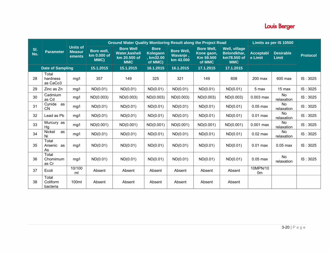
3-20 | P a g e
Sl. No.
Parameter Units of Measurements
Ground Water Quality Monitoring Result along the Project Road Limits as per IS 10500
Protocol Bore well,
km 0.000 of MMC)
Bore Well Water,kasheli km 20.500 of
MMC
Bore Kolegaon, km32.00 of MMC)
Bore Well, Wavanje , km 43.000
Bore Well, Kone gaon, Km 59.500
of MMC
Well, village Belondkhar, km78.550 of
MMC
Acceptable Limit
Desirable Limit
Date of Sampling 15.1.2015 15.1.2015 16.1.2015 16.1.2015 17.1.2015 17.1.2015
28 Total hardness as CaCo3
mg/l 357 149 325 321 149 608 200 max 600 max IS : 3025
29 Zinc as Zn mg/l ND(0.01) ND(0.01) ND(0.01) ND(0.01) ND(0.01) ND(0.01) 5 max 15 max IS : 3025
30 Cadmium as Cd
mg/l ND(0.003) ND(0.003) ND(0.003) ND(0.003) ND(0.003) ND(0.003) 0.003 max No
relaxation IS : 3025
31 Cynide as CN
mg/l ND(0.01) ND(0.01) ND(0.01) ND(0.01) ND(0.01) ND(0.01) 0.05 max No
relaxation IS : 3025
32 Lead as Pb mg/l ND(0.01) ND(0.01) ND(0.01) ND(0.01) ND(0.01) ND(0.01) 0.01 max No
relaxation IS : 3025
33 Murcury as Hg
mg/l ND(0.001) ND(0.001) ND(0.001) ND(0.001) ND(0.001) ND(0.001) 0.001 max No
relaxation IS : 3025
34 Nickel as Ni
mg/l ND(0.01) ND(0.01) ND(0.01) ND(0.01) ND(0.01) ND(0.01) 0.02 max No
relaxation IS : 3025
35 Total Arsenic as As
mg/l ND(0.01) ND(0.01) ND(0.01) ND(0.01) ND(0.01) ND(0.01) 0.01 max 0.05 max IS : 3025
36 Total Chomimum as Cr
mg/l ND(0.01) ND(0.01) ND(0.01) ND(0.01) ND(0.01) ND(0.01) 0.05 max No
relaxation IS : 3025
37 Ecoli 10/100
ml Absent Absent Absent Absent Absent Absent
10MPN/100m
38 Total Coliform bacteria
100ml Absent Absent Absent Absent Absent Absent


3-21 | P a g e
Water Supply Pipe Lines:
Proposed MMC alignment crossing water supply pipelines at 5 (five) location which is presented
in fig 3.4
Proposed alignment crossing Water pipe line at km 20.650 of MMC near Toll Plaza located in Kalher
Proposed MMC alignment crossing water supply pipe lines at existing km557.050 , LHS of NH-3
Water Pipeline run along the RHS of NH-3. Proposed MMC alignment crossing at existing km557.050 of NH-3
MC crossing Water Supply Pipe Chainage 14.300 line, (2 lines) LHS of Katal- Amabarnath-Badlapur Road
MMC crossing Water Supply Pipe Chainage 14.300 line in RHS of Katal- Amabarnath-Badlapur Road
Fig. 3.4. Water Supply Pipelines crosses by the proposed MMC alignment

3-22 | P a g e
3.3.4 Ecological Resources
i) Flora
The flora of the project region and its surrounding is not rich in density except at river or stream
crossings, foot hills of Matheran eco sensitive zone. List of dominant trees occur in the project
areas is presented in Table 3.12
Table 3.12: List of trees along the Project Road
Main species Associate species
Acacia Species Pongamia pinnata
Azadirachta indica Prosopis cineraria (L) Macbr
Melia componita Ficus Sps.
Tamarindus indica Negle marmelos (bel)
Albizia procera
Magnifera indica
Syzysium cumim
ii) Forests
Project road MMC passes through 6.4 km from forest area. Length wise distribution of alignment
of MMC in the Forest area is presented in Table 3.13. Tree enumeration tress and forest land
diversion proposal is under progress therefore after finalization of tree enumeration, the tolal
number of impacted trees in forest and non- forest areas will be furnished in the final EIA report.
Similarly proposed forest land diversion area will be updated in the report after the finalization of
Forest land proposal.
Table 3.13: Abstract of Forest Land Involved Under Proposed Multi Model Corridor Sr. No.
Tehsil & Distt.
Forest Land involved under the Proposed Corridor
Non-Forest Land involved under the Proposed Corridor
Reserved Forest
(Ha.)
Mangroves (CRZ‐
1A) & 50M buffer
involved (Ha.)
Total Forest
area involved
(Ha.)
Non‐ Forest area
involved (Ha.)
1 Tehsil: Vasai
Dist. Palghar
5.9262 3.5314 9.4576 16.8257
2 Tehsil:
Bhivandi
Dist. Thane
2.5719 62.2160 64.7880 164.1669
3 Tehsil: Panvel
Dist. Raigad
8.4982 0.8777 0.8777 327.3548
Grand Total 16.9963
66.6251
75.1233
508.3474

3-23 | P a g e
Sr. No.
Tehsil & Distt.
Forest Land involved under the Proposed Corridor
Non-Forest Land involved under the Proposed Corridor
Reserved Forest
(Sqmt.)
Mangroves (CRZ‐
1A)& 50M buffer
involved (Sqmt.)
Total Forest
area involved
(Ha.)
Non‐ Forest area
involved (Ha.)
1 Tehsil: Vasai
Dist. Palghar
5.9262 3.5314 9.4577 16.825
2 Tehsil:
Bhivandi
Dist. Thane
2.5719
62.21601 64.7881 164.1669
3 Tehsil: Panvel
Dist. Raigad
0.8498 0.08777 0.8777 327.3548
Grand Total 8.4982 66.6252 75.1234
508.3475
iii) National Park:
The project alignment is passing through Sanjay Gandhi National Park about 1.4km. Sanjay
Gandhi National Park (SGNP), previously Borivali National Park, is a large protected area in the
northern part of Mumbai city in Maharashtra State in India. It encompasses an area of 104 km2
(40 sq mi) and is surrounded on three sides by India's most populous city. It is notable as one of
the major national parks existing within a metropolis limit and is one of the most visited parks in
the world.
The park is home to a number of endangered species of flora and fauna. The forest area of the
park houses over 1000 plant species, 251 species of migratory, land and water birds, 50,000
species of insects and 40 species of mammals. In addition, the park also provides shelter to 38
species of reptiles, 9 species of amphibians, 150 species of butterflies and a large variety of fish.
Kadamba, teak, karanj, shisam, and species of acacia, ziziphus, euphorbia, flame of the forest,
red silk cotton and a number of other varieties of flowers. Karvi or karvy, a flowering plant that
flowers once in seven years, can be found in the park.
Chital (or spotted deer), rhesus macaque and bonnet macaque are some of the wild mammals
that can easily be spotted roaming inside the park. Other large mammals found in the park are:
black-naped or Indian hare, muntjac (barking deer), porcupine, Asian palm civet, chevrotain
(mouse deer), Hanuman or grey langur, Indian flying-fox, sambar deer and leopard. One can also
spot striped hyena or four-horned antelope.

3-24 | P a g e
Reptiles living here include: crocodiles in the Tulsi Lake, pythons, cobras, monitor lizards,
Russell's vipers, bamboo pit viper and Ceylonese cat snakes, total 172 species of butterflies have
been reported in the park.Tendua are also observed in the park areas.
Proposed alignment of Multi Model Corridor crosses Sanjay Gandhi National Park, Thane at two
locations:
Location.1
LHS
19020’20.56”N and 72054’42.83”E to 19020’13.66”N and 72054’56.46”E
RHS
19020’16.66”N and 72054’43.31”E to 19020’08.36”N and 72054’59.73”E
Location 2
LHS
19019’49.36”N and 72055’44.43”E to 19019’28.90”N and 72056’05.64”E
RHS
19019’46.59”N and 72055’42.70”E to 19019’24.23”N and 72056’05.15”E
There are Clearing of vegetation and diversion of 14.8ha national Park land is required within the
Sanjay Gandhi National Park therefore permission form the National Board of Wildlife is
necessary.
Fig.3.5: View of SGNP in project area
iv) Wild Life Sanctuary
Only one wildlife sanctuary (Tungreshwar Wildlife Sanctuary, Thane) and one bird sanctuary
(Karnal Bird Sanctuary) is exist within the 10km radius of the project.
a) Tungrshwar Wildlife Sanctuary

3-25 | P a g e
TWLS lies in the Vasai and Bhiwandi talukas in Thane district, It was a tenacious and persistent
follow up by the BNHS with the Government of Maharsahtra and Forest Department along with
BEAG, October 24, 2003, 8,570 hectares or (85.7 sq. km) of Tungareshwar reserved land was
declared, via Gazette Notification No.WLP.1002/CR-47/F-1, as TWLS. An additional 10 sq. km of
reserved forest was recently added as a restoration zone so the total notified forest area of
TWLS is now about 95.70 sq.km.
The Sanctuary protects the two water catchments that supply water to Vasai and Nallsopara.
Leopard is the main predator of the Sanctuary. The main problems that plague TWLS are
religious, agricultural, commercial and residential encroachments in the Sanctuary, if not nipped
in time this bud may flower and flourish like it has in neighboring SGNP.
Proposed Multi Model Corridor passes 153m away from the boundary of Tugareshwar Wildlife
Sanctuary, located in the district of Thane. Nearest location of Tungareshwar Wildlife Sanctuary:
19018’59.03”N and 72056’43.46”E is 153m away from proposed project alignment at
19018’54.35”N and 72056’41.72”E .
Fig.3.6 View of Tungareshwar Wildlife sanctuary
b) Karnal Bird Sanctuary
Karnala Bird Sanctuary (KBS) is located in Panvel Taluka of Raigad District in Maharashtra.
Karnala Bird Sanctuary is spread on the terrains around the historic Karnala Fort in Panvel
Taluk. Karnala Bird Sanctuary is geographically located 12 km away from Panvel Taluk on
the Mumbai-Pune National highway to Goa. Karnala Bird Sanctuary spans an area of 446 sq
km (172 sq miles) covered with deciduous forests consisting different varieties of trees and
plants. Floristic combination of Karnala Bird Sanctuary comprises different species of plants
and trees such as Koshimb, Nana, Mango, Kulu, Umbar, Teak, Asana and Kalam. KBS
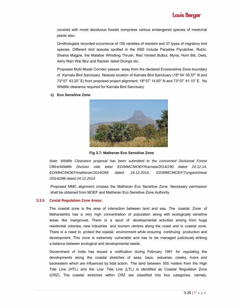
3-26 | P a g e
covered with moist deciduous forests comprises various endangered species of medicinal
plants also.
Ornithologists recorded occurrence of 150 varieties of resident and 37 types of migratory bird
species. Different bird species spotted in the KBS include Paradise Flycatcher, Robin,
Shama Magpie, the Malabar Whistling Thrush, Red Vented Bulbul, Myna, Horn Bill, Owls,
Ashy Rain War Blur and Racket- tailed Drongo etc.
Proposed Multi Model Corridor passes away from the declared Ecosensitive Zone boundary
of Karnala Bird Sanctuary. Nearest location of Karnala Bird Sanctuary (180 54’ 05.57” N and
730 07’ 43.20” E) from proposed project alignment: 180 57’ 14.60” N and 730 07’ 41.10” E. No
Wildlife clearance required for Karnala Bird Sanctuary.
c) Eco Sensitive Zone
Fig 3.7: Matheran Eco Sensitive Zone
Note: Wildlife Clearance proposal has been submitted to the concerned Divisional Forest
Office/Wildlife Division vide letter ED/MMC/MOEF/Karnala/2014/290 dated 24.12.14,
ED/MMC/MOEF/matheran/2014/289 dated 24.12.2014, ED/MMC/MOEF/Tungareshwar
/2014/288 dated 24.12.2014
Proposed MMC alignment crosses the Matheran Eco Sensitive Zone. Necessary permission
shall be obtained from MOEF and Matheran Eco Sensitive Zone Authority.
3.3.5 Costal Regulation Zone Areas:
The coastal zone is the area of interaction between land and sea. The coastal Zone of
Maharashtra has a very high concentration of population along with ecologically sensitive
areas like mangroves. There is a spurt of developmental activities arising from huge
residential colonies, new industries and tourism centres along the coast and in coastal zone.
There is a need to protect the coastal environment while ensuring continuing production and
development. This zone is extremely vulnerable and has to be managed judiciously striking
a balance between ecological and developmental needs.
Government of India has issued a notification during February 1991 for regulating the
developments along the coastal stretches of seas, bays, estuaries, creeks, rivers and
backwaters which are influenced by tidal action. The land between 500 meters from the High
Tide Line (HTL) and the Low Tide Line (LTL) is identified as Coastal Regulation Zone
(CRZ). The coastal stretches within CRZ are classified into four categories, namely,

3-27 | P a g e
Category I (CRZ-I), Category II (CRZ-II), Category III (CRZ-III) and Category IV (CRZ- IV).
The notification has also laid down regulations to regulate the various activities in the
coastal zone. The Ministry of Environment and Forests, Government of India, has approved a
set of CRZ maps on 1:25,000 scale prepared from SPOT satellite imagery. On these maps,
zones are demarcated as CRZ I, CRZ II and CRZ III, by Coastal Zone Management
Authority.
Coastal Regulation Zone I includes the zone between High Tide Line and Low Tide Line. It
also includes the areas that are ecologically sensitive and important, such as national
parks/marine parks, sanctuaries, reserve forests, wildlife habitats, mangroves, corals/coral
reefs, areas close to breeding and spawning grounds of fish and other marine life, areas of
outstanding natural beauty/historically/heritage areas, areas rich in genetic diversity, areas
likely to be inundated due to rise in sea level consequent upon global warming and such other
areas as may be declared by the Central Government or the concerned authorities at the
State/Union Territory level from time to time.
CRZ-II covers the areas that have already been developed up to or close to the shoreline.
For this purpose, the "developed area" is referred to as that area within the municipal limits or in
other legally designated urban areas which are already substantially built up and have been
provided with drainage and approach roads and other infrastructural facilities, such as water
supply and sewerage mains. CRZ-III covers the areas that are relatively undisturbed and those
which do not belong to either Category-I or II. These include the coastal zone in the rural
areas (developed and undeveloped) and also areas within municipal limits or in other legally
designated urban areas which are not substantially built up. CRZ-IV refers to the coastal
stretches in the Andaman and Nicobar, Lakshadweep and small islands other than those
designated as CRZ-I, CRZ-II or CRZ-III.
The Ministry of Environment and Forest in the CRZ Notification, 2011 declared the following
areas as CRZ and imposed with effect from the date of the notification the restrictions on the
setting up and expansion of industries,
operations or processes and the like in the CRZ. The areas that are defined as CRZ as per
CRZ Notification, 2011 are
The land area from High Tide Line (HTL) to 500mts on the landward side along the sea front.
CRZ shall apply to the land area between HTL to 100 meters or width of the creek
whichever is less on the landward side along the tidal influenced water bodies that are
connected to the sea and the distance upto which development along such tidal influenced
water bodies is to be regulated shall be governed by the distance upto which the tidal effects
are experienced which shall be determined based on salinity concentration of 5 parts per
thousand (ppt) measured during the driest period of the year and distance upto which tidal
effects are experienced shall be clearly identified and demarcated accordingly in the Coastal
Zone Management Plans.
3-28 | P a g e
The land area falling between the hazard line and 500mts from HTL on the landward side,
in case of seafront and between the hazard line and 100mts line in case of tidal influenced
water body the word
„hazard line‟ denotes the line demarcated by Ministry of Environment and through the
Survey of India taking into account tides, waves, sea level rise and shoreline changes.
Land area between HTL and Low Tide Line (LTL) which will be termed as the intertidal zone.
The water and the bed area between the LTL to the territorial water limit (12 Nm) in case of sea
and the water and the bed area between LTL at the bank to the LTL on the opposite side of the
bank, of tidal influenced water bodies.
The Classification of the CRZ is also modified for the purpose of conserving and protecting the
coastal areas and marine waters as CRZ – I, CRZ – II, CRZ – III and CRZ – IV. The CRZ
– I include the areas that are ecologically sensitive and the geomorphological features which
play a role in the maintaining the integrity of the coast like (a) Mangroves(b) Corals and
coral reefs and associated biodiversity (c) Sand Dunes (d) Mudflats which are biologically active
(e) National parks, marine parks, sanctuaries, reserve forests, wildlife habitats and other
protected areas (f) Salt Marshes (g) Turtle nesting grounds (h) Horse shoe crabs habitats (i)
Sea grass beds (j) Nesting grounds of birds (k) Areas or structures of archaeological
importance and heritage sites and the area between Low Tide Line and High Tide Line. The
CRZ-II includes areas that have been developed upto or close to the shoreline. The CRZ-III
includes areas that are relatively undisturbed and those do not belong to either CRZ-I or II,
which include coastal zone in the rural areas (developed and undeveloped) and also areas
within municipal limits or in other legally designated urban areas, which are not substantially
built up. The CRZ-IV includes the water area from the Low Tide Line to twelve nautical miles on
the seaward side and the water area of the tidal influenced water body from the mouth of the
water body at the sea upto the influence of tide which is measured as five parts per thousand
during the driest season of the year.
The Ministry of Environment and Forest has also provided guidelines for demarcation of High
Tide Line in the CRZ Notification, 2011. As per the guidelines, Cadastral (village) maps in
1:3960 or the nearest scale shall be used as the base maps. HTL and LTL will be
demarcated in the cadastral map based on detailed physical verification using coastal
geomorphological signatures or features in accordance with the CZM Maps approved by the
Central Government. 500metre and 200metre lines shall be demarcated with respect to the HTL.
CRZ mapping is carried out by Anna Malai university which is approved from MOEF for
conducting CRZ mapping. According to CRZ mapping of the project area village wise and CRZ
class wise area is presented in Table 3.14 As per CRZ notification 2011 and Table 3.15 are as
per CRZ notification 1991.
Table 3.14: Project Alignment in CRZ area as per CRZ notification 2011
Sl. No Village CRZ Classification Area in sq.m
Taluka Bhiwandi
1 Anjur CRZ-IA (Mangroves & 50m Buffer) 5,909

3-29 | P a g e
Sl. No Village CRZ Classification Area in sq.m
Taluka Bhiwandi
CRZ-IB 120
CRZ-III 10,348
2 Bharodi
CRZ-IA (Mangroves & 50m Buffer) 81,192
CRZ-IB 3,608
CRZ-III 18,193
CRZ-IVB 6,620
3 Dive
CRZ-IA (Mangroves & 50m Buffer) 1,23,678
CRZ-IB 2,17,181
CRZ-III 1,44,052
4 Dunge
CRZ-IA (Mangroves & 50m Buffer) 31,916
CRZ-IB 309
CRZ-III 13,577
5 Kalher
CRZ-IA (Mangroves & 50m Buffer) 50,612
CRZ-IB 47,505
CRZ-III 1,00,360
6 Kasheli
CRZ-IA (Mangroves & 50m Buffer) 1,04,590
CRZ-IB 14,135
CRZ-III 76,119
7 Kewani
CRZ-IA (Mangroves & 50m Buffer) 15,527
CRZ-IB 19,974
CRZ-III 45,641
8 Kharbav
CRZ-IA (Mangroves & 50m Buffer) 42,344
CRZ-IB 4,530
CRZ-III 33,284
9 Kopar CRZ-IB 2,341
CRZ-III 7,766
10 Malodi
CRZ-IA (Mangroves & 50m Buffer) 12,951
CRZ-IB 28,277
CRZ-III 59,766
11 Paye
CRZ-IA (Mangroves & 50m Buffer) 1,15,710
CRZ-IB 26,028
CRZ-III 54,979
12 Paygoan
CRZ-IA (Mangroves & 50m Buffer) 16,933
CRZ-IB 1,032
CRZ-III 8,046

3-30 | P a g e
Sl. No Village CRZ Classification Area in sq.m
Taluka Bhiwandi
13 Vadunavghar
CRZ-IA (Mangroves & 50m Buffer) 22,055
CRZ-IB 1,781
CRZ-III 9,774
Taluka Vasai
1 Bapane
CRZ-IA (Mangroves & 50m Buffer) 21,721
CRZ-IB 34,756
CRZ-III 52,629
2 Juchandra
CRZ-IA (Mangroves & 50m Buffer) 9,568
CRZ-IB 84
CRZ-III 5,141
3 Kaman CRZ-III 151
4 Mori
CRZ-IA (Reserved Forest) 50,035
CRZ-IB 93
CRZ-III 1,386
5 Nagle CRZ-IA (Reserved Forest) 59,487
CRZ-III 966
6 Sarjamori
CRZ-IA (Mangroves & 50m Buffer) 926
CRZ-IB 69,860
CRZ-III 14,309
7 Saunavghar
CRZ-IA (Mangroves & 50m Buffer) 1,740
CRZ-IA (Reserved Forest) 15,775
CRZ-IB 5,096
CRZ-III 9,230
Taluka Kalyan
1 BHOPAR
CRZ-IA (Mangroves & 50m Buffer) 35,362
CRZ-IB 2,236
CRZ-III 49,462
CRZ-IVB 18,567
Taluka Thane
1 Belondakhar CRZ-IB 1,187
CRZ-III 8,388
2 Kauli Bandhankar
CRZ-III 367
Source: CRZ mapping, IRS, Anna University, Chennai
Table 3.15: Project Alignment in CRZ area as per CRZ notification 1991

3-31 | P a g e
Sl. No
Village CRZ Classification Area in sq.m
Taluka Bhiwandi
1 Bharodi CRZ-III 10,835
CRZ-IVB 88,577
2 Dive
CRZ-III 91,468
CRZ-IVB 74,161
3 Dunge CRZ-III 22,065
CRZ-IVB 24,894
4 Kalher CRZ-III 34,415
CRZ-IVB 485
5 Kasheli CRZ-III 10,635
CRZ-IVB 2,14,809
6 Kewani CRZ-III 53,384
CRZ-IVB 16,268
7 Kharbav CRZ-III 9,938
CRZ-IVB 13,596
8 Malodi CRZ-III 88,466
CRZ-IVB 13,276
9 Paye CRZ-III 68,836
CRZ-IVB 108,728
10 Paygoan CRZ-III 26,394
CRZ-IVB 11,206
11 Vadunavghar CRZ-III 27,909
CRZ-IVB 14,938
Taluka Vasai
1 Bapane CRZ-III 32,602
CRZ-IVB 2,816
2 Juchandra CRZ-III 7,272
CRZ-IVB 10,096
3 Nagle CRZ-III 4,809
4 Sarjamori CRZ-III 3,445
Taluka Kalyan
1 Bhopar CRZ-III 57,395
CRZ-IVB 71,476
Source: CRZ mapping, IRS, Anna University, Chennai
i) Mangroves and 50m Buffer

3-32 | P a g e
Project alignment will affect 69.2743ha mangroves and its 50m buffer areas (as per CRZ
notification 2011). Village wise mangroves and its 50m buffer areas are to be affected from the
proposed alignment of MMC is presented in above Table 3.15.
MCZMA has recommend CRZ proposal to MOEFCC on their 113th Meeting held on 9th to
10th Aug 2016.
3.4 AVAILABILITY OF CONSTRUCTION MATERIAL
An initial inventory program was undertaken to identify suitable sources of all construction
materials such as soil, sand, stone aggregates and other materials like cement, steel and
bitumen. The Consultants conducted necessary surveys to find out the characteristics of
materials available in the area. Furthermore, the locations of quarries and borrow areas were
reviewed and noted from the corresponding projects of MMRDA in and around the project area to
the extent available.
Construction material can be made available from the quarry area which has been identified by
the feasibility engineer keeping in mind the following:
Sufficient quantity of suitable soil is available from the borrow pit
The borrow areas are as close to the project road as far as possible
The loss of productive and fertile agricultural soil is minimum and
There is minimal loss of vegetation.
And also have valid permissions
Location of the availability of Borrow Quarries area, Sand Source and its quantity is to be used in
construction of MMC of the project road is given in Table 3.16

3-33 | P a g e
Table 3.16: Construction Material
Material Location Distance from
Alignment Availability of material (cum)
Murum
Chinchoti Anjur Phata Road 1.5km 242580
Nitlas Village of kalyan Road 0.5km 2229556
Nitlas Village of kalyan Road 2.2km 1680000
Aggregate
Chinchoti Anjur Phata Road 2.25km 2991800
Near Bhiwandi lake 4.46km 176120
Mumbai nasik Highway NH-222 Junction
7km
Of NH-4B 0.25km 40284390
Of NH-4B 0.25km 14971027
Of NH-4B on Thal Road 3.20km 3433800
Of NH-4B on Near RCF Thal 4.15km 6520808
i) Fly ash
Keeping in mind the provisions of the fly ash notification, 14th September 1999, as amended up to
17th August 2003 under the Environment (Protection) Act and the vicinity to the thermal power
plant, fly ash will be utilized for the project.
There are two thermal power plant located within the 100km radius from the alignment viz. (a)
Tata Thermal Power Plant, Trombay, Mumbai about 30km away from the project alignment
and(b) Dahanu Thermal Power Station, Dahanu, Thane- 70km away from the project alignment.
3.5 SOCIAL ENVIRONMENT
3.5.1 Archaeological and Cultural Properties
No Archaeological monument conserved by ASI is located within project areas.
There are 7 numbers of cultural properties existing along the proposed project road out of them 3
will be affected from the construction of MMC. List of these properties are presented in table 3.17
and Fig. 3.8
Table 3.17: List of religious properties along the project
Chainage (km) Religious Properties
Distance from Proposed Centerline
Remarks
6.550 Temple 50m Not Impacted
20.500 Temple 5m Impacted
33.550 Temple 10m Not Impacted
44.000 Mosque 50m Not Impacted
67.150 Temple 20m Impacted
70.050 Mosque 70m Not Impacted
70.100 Temple 5m Impacted

3-34 | P a g e
Temple, MMC km6.550, 50m
Fig.3.8: Religious Properties along the Project Road
3.5.2 Settlements and Properties
There are 42 number of village/market/town recorded along the proposed alignment of MMC
project road (Table 3.18)
Table3.18: List of village along the MCC project
Sr. No.
Village Sr. No
Village Sl. No Village name
1 Barham Pur 16 Dongagaon 31 Motijhoni
2 Umelman 17 Kalwar 32 Digora
3 Navghar 18 Kasarvadoli 33 Saigaon
4 Rajoali 19 Anjur 34 Dapoli
5 Tihuri 20 Kopargaon 35 Dadar Para
6 Joochandra 21 Kalher 36 Dronagiri
7 Sarjja 22 Kehulidive 37 Navghar
8 Chandra
Para 23 Mankholi 38 Bhendghar
9 Khopari Parra
24 Balgaon 39 Kopta
10 Kamman
Road 25 Daptoa 40 Koproli
11 Silotar 26 Gundoli 41 Mothijuhi
12 Nagla 27 Allimghar 42 Chirner
13 Paya Gaon 28 Kolkhegaon
14 Kharbhav 29 Nadgaon 15 Barghar 30 Chindoli

3-35 | P a g e
3.6 OTHER FEATURES OF PROJECT AREA OF INFLUENCE (PIA)
3.6.1 Industries
There are two critically polluted industrial area notified by CPCB located within the 10km radius of
the project alignment. Dombivili (MIDC Phae-I&Phase-II) is critically polluted Industrial area exist
2.350km away from the MMC alignment and Navi Mumbai (TTC Industrial area, Kalwa and
Mahape) located 8.5 km away from the proposed alignment of MMC.
Critically Polluted Notified Area, Dombivili
Critically Polluted Notified Area, MIDC, Navi Mumbai
Fig.3.9: Critically Notified Areas on google image

3-36 | P a g e
3.6.2 Educational Institutes
There are 3 educational institutions exists along the project alignment and none of them are going
to be impacted from the proposed project.
3.6.3 Land Use Pattern
The land use pattern of the project area consists of agricultural, residential, mangroves, reserve
forests, National Park, Orchards, quarry areas, creeks, river. Paddy, sugarcane, cotton are the
predominant crops of the project area. Fig.3.10 showing the land use along the Project Road
areas. The land use along the road is presented in google map and in G.T. Sheet as Annexure
3.1 and Annexure 3.2 respectively.
Mud land, back water, km 0.350 Land use at km 20.750 : mangroves, and low land
Land Use at km 25.000 Land Use at km 32.750
Land Use at km 33.550 Land Use at km 67.000
Fig.3.10: Land use of the Project Area

3-37 | P a g e
PHOTO: ENVIRONMENTAL MONITORING ALONG THE PROJECT ROAD
Surface Water Quality Monitoring along the Project
Pond at km 43.600 Pond at km 32.250
Water Quality Monitoring at km 26.900 Panvel River, km66.500

3-38 | P a g e
Ground Water Quality Monitoring
Bore well water at km 0.000 of MMC At km 20.500 of MMC, Kasheli village
Km32.00 of MMC, Village Wavanje Km43.000 of MMC, Near Enkay School

3-39 | P a g e
Photos: Ambient Air Quality Monitoring along the alignment of MMC At Km. 0.000 of MMC - Chandika Hotel Left Side (Site 1) (Date 14.01.15)
At km 6.00 of MMC near Chincoti-Anjur Phata Road (Site- 2) (Date 14.01.15)
At Km. 32.000 of MMC Crossing of Pipeline Road (Site- 3) (Date 17.01.15)
Wavenje Vill. (Km 43.000 of MMC Matheran Eco Sensitive Zone Area) (Site 4) Date 16.01.15
Near Village (Km. 56.000 of MMC Matheran Eco- Sensitive Zone Area) (Site- 5) Date 16.01.15
Kone Village (Km 61.500 of MMC NH-4 Crossing) (Site- 6) Date 15.01.15
CH 78.55Kh on Village Road Belondakhar Village (Site 7) Date 15.01.15

3-40 | P a g e
Photos: Ambient Noise Level Monitoring along the alignment of MMC
Starting point of Multi Model Corridor (at Km. 0.000 of MMC) (Site- 1) Date 15.1.15
At Km. 6.00 of MMC near Chincoti-Anjur Phata Road (Nagla Village) (Site 2) Date 15.1.15
Kolegaon (Km 32.000 of MMC Crossing of Pipeline Road) (Site 3) Date 18.1.15
Wavenje Vill. (Km. 43.000 of MMC Crossing of Pipeline Road, Inkey School) (Site 4) Date 17.1.15
Near Village (Km. 56.000 of MMC Matheran Eco Sensitive Zone Area) (Site 5) Date 17.1.15
Kone Village (Km 61.500 of MMC NH-4 Crossing) (Site- 6) Date 16.1.15
CH- 78.55 Km on Village road Belondakhar Village (Site 7) Date 16.1.15


i | P a g e
TABLE OF CONTENTS
CHAPTER - 4: ANTICIPATED IMPACTS AND MITIGATION MEASURES ......................................... 4-1
PART-1: ANTICIPATED IMPACTS ....................................................................................................... 4-1
4.1 GENERAL .................................................................................................................................... 4-1
4.1.1 Impacts on Physical Environment ................................................................................... 4-2
4.1.2 Impact on soil .................................................................................................................. 4-3
4.1.3 Contamination of Soil ...................................................................................................... 4-3
4.1.4 Impact of Soil Borrow Areas ............................................................................................ 4-4
4.1.5 Impact on Water Resources ............................................................................................ 4-4
4.1.6 Impacts on Air Environment ............................................................................................ 4-6
4.1.7 Noise environment .......................................................................................................... 4-7
4.1.8 Impact on Ecological Resources ..................................................................................... 4-9
4.1.9 Impact on Cultural Environment .................................................................................... 4-11
4.2 IMPACT ON SOCIO -ECONOMIC ENVIRONMENT ................................................................... 4-11
4.2.1 Scope and Objectives ................................................................................................... 4-11
4.2.2 Methodology ................................................................................................................. 4-12
4.2.3 Likely Loss of Properties ............................................................................................... 4-13
4.2.4 Type of Commercial Structures likely to be affected ..................................................... 4-13
4.2.5 Loss of Land ................................................................................................................. 4-14
4.2.6 Impacted Persons ......................................................................................................... 4-15
4.2.7 Vulnerable Households ................................................................................................. 4-15
4.2.8 Religious Properties ...................................................................................................... 4-15
4.2.9 Type of Utilities Likely To Be Affected ........................................................................... 4-15
4.2.10 Impact on Safety and Public Health Road Safety .......................................................... 4-16
4.3 PART-2: MITIGATION, AVOIDANCE AND ENHANCEMENT MEASURES .............................. 4-17
4.3.1 Overview ....................................................................................................................... 4-17
4.3.2 Meteorological Parameters ........................................................................................... 4-17
4.3.3 Topography ................................................................................................................... 4-17
4.3.4 Geology and Soil........................................................................................................... 4-18
4.3.5 Loss of Agriculture Land ............................................................................................... 4-21
4.3.6 Water Environment ....................................................................................................... 4-21
4.3.7 Air Environment ............................................................................................................ 4-23

ii | P a g e
4.3.8 Noise Environment ........................................................................................................ 4-25
4.3.9 Construction Camp ....................................................................................................... 4-26
4.3.10 Facilities at workers camps ........................................................................................... 4-27
4.3.11 Ecology ......................................................................................................................... 4-27
4.3.12 Enhancement Measures ............................................................................................... 4-28
4.3.13 Natural Environment ..................................................................................................... 4-29
4.3.14 Road Safety .................................................................................................................. 4-31
4.3.15 Cultural Environment .................................................................................................... 4-32
4.3.16 R&R and Land Acquisition Cost .................................................................................... 4-32
4.3.17 Institutional Arrangement .............................................................................................. 4-33
LIST OF TABLES
Table 4.1: Impacts on Water Resources and Indicators ....................................................................... 4-4
Table 4.2: Typical noise levels of principal construction equipments ...................................................... 4-7
Table 4.3 Summary of impacted CRZ and Wildlife area ....................................................................... 4-10
Table 4.4: Likely Loss of Properties in the Project Road ...................................................................... 4-13
Table 4.5: Type of Commercial Structures Likely to be affected ........................................................... 4-14
Table 4.6: Village likely to be affected by Land Acquisition .................................................................. 4-14
Table 4.7: Preliminary Project Affected peoples ................................................................................... 4-15
Table 4.8: Vulnerable Families/ Persons .............................................................................................. 4-15
Table 4.9: Type of Utilities Likely to be affected ................................................................................... 4-16
Table 4.10: Silt Fencing Locations ........................................................................................................ 4-22
Table 4.11: Sources of Air Pollution, Impacts and Suggested Mitigation Measures ............................. 4-24
Table 4.12: Sources of Noise Pollution, Impacts and Suggested Mitigation Measures ......................... 4-26
Table 4.13: Trees recommended for plantation along Project Road ..................................................... 4-30


4-1 | P a g e
CHAPTER - 4: ANTICIPATED IMPACTS AND MITIGATION MEASURES
PART-1: ANTICIPATED IMPACTS
4.1 GENERAL
The project Multi Modal Corridor is a single corridor in which multiple modes, such as buses,
BRT, metro rail and cars, along with utilities such as water, sewage and gas lines are present in
the same Right of Way. The Right of way (ROW) of Proposed Multi Modal Corridor is 99 meters”.
Proposed construction of Multi Model Corridor (MMC) from Navghar to Chirner will cause
biophysical and socio-cultural impacts. The nature and magnitude of impacts vary depending on
the character of components of construction works and the physical and socio-economic setting
in which such project is located.
This coupled with the fact that the project road (MMC) is passing through the Sanjay Gandhi
National Park and Matheran Eco Sensitive Zone. No other sensitive area or properties like
monuments/ heritages are to be directly impacted or falling with in the proposed MMC. Impacts
have been assessed based on the information collected during the field surveys and available
additional secondary data collected as part of the EIA study.
The project MMC is traversing through agricultural areas, mangroves areas, low lands and from
forest areas at some locations.
Although most of the works are planned to be carried out within the proposed ROW (99m) except
road interchanges where flyover proposed. However, proposed project is a new green field
alignment therefore, acquisition of non-forest land diversion of National Park area, Eco-sensitive
areas and forest areas will be involved for the proposed activities. While selecting the MMC
alignment the stress has been given to keep in mid view of less acquisition of structures, forest
areas. National Park land etc. In this chapter only environmental related issues have been
discussed.
During the various surveys, consultations and site investigations, a number of environmental
issues were identified and discussed. For all the identified issues and potential impacts effective
mitigation and avoidance measures were considered and included in the report. During the EIA
process major and minor issues were classified and provided in the bellow table.

4-2 | P a g e
Identified environmental issues/and impacts
CORRIDOR NAME
MAJOR ISSUES OTHER ISSUES
Mu
lti M
od
el C
orr
ido
r (N
avg
har
–
Ch
irn
er,
Len
gth
80k
m)
Cutting of Trees in non Forest area or private land Cutting of tree exist in proposed ROW of project MMC
falling under Forest Areas Water for construction Loss of agricultural areas Loss of Mangroves Social impacts including land acquisition and
resettlement Impact to wildlife- traffic/wildlife conflict Replacement of Bore well Provision for parking areas Impact to religious properties Longitudinal and cross drainage Stabilization of slopes Impact to religious properties
Shifting of Water Supply Pipeline, Operational phase impacts, Health and safety issues during construction and operational phases.
The qualitative and quantitative assessment of bio-physical and socio-cultural environmental
components can have direct or indirect impacts and such impacts are described in the following
sections and proposed mitigation measures are presented in second part of this chapter.
4.1.1 Impacts on Physical Environment
4.1.1.1 Impact on Meteorology
The project will involve removal of trees and mangroves from the proposed ROW of MMC in
forest and non- forest areas. No. of trees in of National Parks area, forest areas, and non-forest
areas will be finished after the final tree enumeration in proposed ROW of MMC. Removal of
trees and mangroves from the proposed project corridor will result in temporary loss of shade for
some areas causing some discomfort for local people. The paving of surfaces will also lead to
very minor changes in temperature. However, with the provision of grass turf on the embankment
and restoration of the vegetal cover through compensatory afforestation. There will be minimal
impacts on the micro-meteorology of the project impact corridor.
4.1.1.2 Impact on Physiography
The maximum portion of the project is passes through plain terrain, except at few location close
to Matheran Eco Sensitive area, near Panvel there is rolling terrain and also crosses the Sanjay
Gandhi National park about 1.4km. There will be substantial cutting will be required at or near Hill
areas. In low lying areas, elevated road/rail is proposed. Cutting material will be utilized in raising
embankment of the proposed corridor. However the storage of materials at identified sites may
cause very minimal changes in Physiography only for a temporary period. The impact therefore
on the corridor will be very low and insignificant.
4.1.1.3 Impact on Topography
The overall topography of vicinity of the project will have little impacted in terms of change in land
use.
4-3 | P a g e
4.1.1.4 Impact on Geology
The project area is represented by alluvium soil and there is no area, which can be termed as
fragile. Collection and transportation of material from identified quarries and borrow pits may
cause very little or insignificant impact on the geology of the project corridor. Moreover, geology
of the area may be impacted due to Quarrying operations. In this project the requirement of
coarse aggregate is high. Moreover, both existing and new quarries will be used if, it has valid
NOC.
4.1.2 Impact on soil
4.1.2.1 Loss of productive Soil
The proposed project MMC (Navghar to Chirner) will require diversion of N.P, RF, Eco-sensitive
Zone, and agricultural land. This is a minimal change in land use and therefore, the impact on
agriculture production will be very low. This is also not going to have an adverse impact on the
hydrology of the project corridor. There may be temporary loss of production during construction
stage if workers camps, stockyards and borrow areas are established on agricultural land. Use of
some lands for haul loads and traffic detours may cause minimal, temporary and short term
impact on productivity of the project corridor.
4.1.2.2 Soil Erosion
Pre-construction Stage
Site clearance and cutting of trees may set the process of soil erosion.
Construction Stage
Embankment height of the corridor will higher than the ground level. In low lying areas, elevated
road is proposed. At interchanges of the corridor will have elevated structure. However, on
approaches to the ROB/VUP the embankments will be higher from ground level. During
construction if, proper drainage is not maintained then soil erosion process may be set in.
Operation Stage
Slope embankments will be provided with the grass turf and run off from the project corridor shall
be safely disposed off to the existing drainage system to prevent any possibility of soil erosion.
The vegetal cover that will come up through compensatory afforestation will also hold the soil
firmly through their root system and also by cutting down on quantum of precipitation reaching
the ground through canopy interceptions and evaporation through canopy foliage.
4.1.3 Contamination of Soil
Construction Stage
Soil contamination may take place in the construction stage through construction of labour-
camps; stockyards and construction of camping sites for parking of construction machinery
equipment, movement of construction machinery, vehicles during construction especially haul
roads. Sub soil contamination may also be attributed to:
Scarified bitumen wastes

4-4 | P a g e
Maintenance of the machinery and operation of the diesel generator sets on site
Oil Spill from the operation of the mechanical work shops, diesel pumps and diesel
storage, during transportation and transfer, parking places, and diesel generator sets
Operation of the emulsion sprayer and laying of hot mix
Operation of the residential facilities for the labour and staff
Storage and stock yards of bitumen and emulsion
Excess production of hot mix and rejected materials
Operation Stage
During this stage there is possibility of soil contamination by spills from accidents or leakage from
vehicles carrying hazardous chemicals. The probability of incidents is low and such impacts will
depend to a great extent on how such situations are handled on ground.
4.1.4 Impact of Soil Borrow Areas
Extraction of materials from soil borrow areas can result in direct or indirect impact on local
environment. The earth will be taken from borrow areas which may result in loss of productive
soil, Change in topography.
4.1.5 Impact on Water Resources
Due to the proposed project there will be some impacts on the water resources. The typical
impacts on water resources and indicators of the impacts during the construction and operation
stage of the project are given below in the Table 4.1.
Table 4.1: Impacts on Water Resources and Indicators
Water Resources Indicators
Surface Water Bodies Water quality degradation, Siltation
Ground Water Sources Loss of, tube wells and wells
Alteration of drainage, lack of adequate drainage
Overtopping, flooding, water logging
Depletion of ground water Increase in Ground water level
Impact on Surface Water body
The Project MMC is crossing 5 rivers, 18 streams and 12 ponds exists within or along the
proposed corridor, for location detail Refer Table 3.9 and 3.10 of Chapter 3. These surface
water bodies may be impacted in terms of degradation in water quality and increase in sediment
load during construction if EMP recommendation will not be followed.
Pre-construction stage
Water resources can get impacted through increase in sediment load arising out of stripping of
ground and tree vegetation for establishment of workers camps, stock yards for materials,
camping grounds for equipments etc. Such impacts will be short term and largely mitigable
through management measures. Temporary increase in turbidity may also temporarily affect
aquatic flora and fauna resulting in their migration to safer stretches of surface water.

4-5 | P a g e
Construction Stage
The Project MMC is crossing 5 rivers, 18 streams and 12 ponds exists within or along the
proposed corridor, for location detail Refer Table 3.9 and 3.10 of Chapter 3. The existing 12
pond are seems to be a part of discarded quarry area located within the proposed alignment of
project MMC. The water quality of these surface water bodies may degrade due to falling of
construction materials, spoils or inflow of silt because of soil erosion along the bank river, stream
distributary during construction stages. The storage of materials and construction wastes may
also add to such sediment load. The construction activities on this live canal will be carried out
when there will be no flow of water which will result in disruption of water supply to the
downstream user. The sources of water pollution from the construction activities include the
following:
Storage and stockyards of bitumen and emulsion.
Oil spill from the operation of the mechanical workshop, diesel pumps, diesel storage,
transportation and transfer
From the foundation work of bridges and culverts such as piling and excavation for open
/ well foundation
Operation of construction camps
Water flow from scarified bitumen material
Operation of emulsion sprayer and laying of hot-mix.
There will be increased surface run-off because of construction of new pavements resulting in
sealing off a substantial permeable surface and removal of vegetation cover leading to loss of
evapo-transpiration and increased through-fall. Increased through-fall may to some extent negate
the impact of sealing particularly in areas where the vegetal cover exists currently.
Operation Stage
There is very little chance of deterioration in water quality in this stage. This may happen only in
case of accidental spills. As all safety measures will become operative during the operation
phase there is very less probability of such incidents
4.1.5.1 Impact on Ground water
There is only 1 tube-well/bore well and 11 hand pumps are exists along the project corridor which
will be affected. The loss of the tube wells and Hand pumps will be a loss to the communities,
which have been using these as water resources. The water will be extracted from river/stream/
ground water for construction after approval from concerned authority but as total water required
for construction activity including for domestic use in labour camp is 360KLD only. This demand
is spread over for period of 30 months, so no major impact is anticipated.
4.1.5.2 Alteration of Cross Drainage
Such changes can be attributed to the construction of new bridges. The details of major cross
drainage structures are furnished in Table 3.9 of chapter-3, construction activities may result in
obstruction to flow in short term and localised.

4-6 | P a g e
4.1.5.3 Increased Surface Run-off
Provision of MMC will result to increase in run-off quantum through reduction in water infiltration.
The increase paved area is not being significant, and will not have any major impact on the
ground water table.
4.1.6 Impacts on Air Environment
Table 3.5 showed that all the parameters monitored are within the permissible limits except PM10
because of project MMC is passing through the agricultural areas and the monitoring was carried
out in winter season at the time of paddy harvesting.
Pre-construction Stage
The pre-construction stage is characterized by activities like site clearance, tree cover removal,
shifting of utilities, transportation of men and material, establishment of construction camps,
stockyards, installation of plants and equipments. All these activities lead to generation of dust
especially when such activities are undertaken during the dry season. Such impacts are Short-
term, location specific, temporary and reversible.
Construction Stage
The most important pollutant during this phase will be suspended particulate matter along with
gaseous pollutants like dioxides of nitrogen, sulphur, and carbon monoxide. Such deterioration of
air quality can be assigned to:
Fugitive dust emission from construction activities like excavation, back-filling and
concreting
Hauling and dumping of earth & construction spoils and vehicular movement along
unpaved roads or temporary diversions
Gaseous emission from construction equipment and vehicular traffic
Emissions from asphalt and hot-mix plants
Such impacts will be felt locally as well as along the project MMC particularly at the sites of
bridge construction and the spans of the project taken up for rehabilitation.
Generation of Dust
Dust generation due to procurement and transport of raw materials from quarries and borrow
pits, site clearance, use of heavy vehicles, machinery/ equipment, stone crushing, handling and
storage of aggregates and generation of fine particulate matter (smoke) in asphalt processing will
be responsible for short-term and localized degradation of air quality.
Generation of Exhaust Gases
Hot mix plants contribute substantially to the deterioration of air quality due to emissions of
oxides of sulphur, hydrocarbons and particulate matter. During this stage, due to the increased
speed and volumes of vehicular traffic on the project corridor, marginal increase in the air
pollutant levels, is expected but not significant.

4-7 | P a g e
Operation Stage
This stage is characterized by increased intensity of vehicular movement because of improved
connectivity thereby increasing pollution load. The impacts of oxides of nitrogen, carbon
monoxide, and respirable particulate matter will increase with the increasing number of vehicles
using this project road. Such impacts will be of long term and will be felt within a corridor width of
75m –100m on both sides from the edges of the project road. The abrasive action of tyres will
also add to degradation in air quality.
4.1.7 Noise environment
Ambient noise quality was monitored at three locations representative of a residential, Eco
sensitive Zone and silent zone along the corridor. At all these locations the noise level are within
the permissible standard. Noise quality level during daytime is comparatively higher than those of
during night. This definitely is indicative of a very high degree of use of the road stretch by the
vehicular traffic.
Pre-Construction stage
The noise level will not be impacted appreciably at this stage (Table 3.7 and Table 3.8 of
chapter-3). The noise levels may increase due to pre construction activities like establishment of
workers’ camps, movement of construction materials and movement of machineries and
equipments for construction. This impact of increased noise level will be localized, short-term and
reversible.
Construction Stage
Impacts during this stage are going to be significant for the communities residing along the
project corridor. Impacts on different receptors will also vary considerably during the construction
stage and these impacts will be localized and limited to stretches where construction work will be
under progress, near Equipment / vehicle yard, Plant sites. The machineries and equipment
used in construction during their operation add significantly to the noise level. Proper scheduling
of operation of such machineries during the construction phase may to a great extent attenuate
the noise level leading to lessening of the discomfort level of the affected communities. Other
activities related to construction that affect noise quality include stone crushing, asphalt
production and batching plants and diesel generators.
Operation Stage
During operation stage noise levels will slightly decrease due to decongestion of traffic load on
this project road. Noise will be mitigated by planting trees along the project road as noise barrier.
Typical noise level of construction equipments is provided in Table 4.2.
Table 4.2: Typical noise levels of principal construction equipments
(Noise Level in db (A) at 50 Feet)
Clearing Structure construction
Bulldozer 80 Crane 75-77
Front end loader 72-84 Welding generator 71-82

4-8 | P a g e
Clearing Structure construction
Jack hammer 81-98 Concrete mixer 74-88
Crane with ball 75-87 Concrete pump 81-84
Concrete vibrator 76
Excavation and Earth Moving Air compressor 74-87
Bulldozer 80 Pneumatic tools 81-98
Backhoe 72-93 Bulldozer 80
Front end loader 72-84 Cement and dump trucks 83-94
Dump truck 83-94 Front end loader 72-84
Jack hammer 81-98 Dump truck 83-94
Scraper 80-93 Paver 86-88
Grading and Compaction Landscaping and clean-up
Grader 80-93 Bulldozer 80
Roller 73-75 Backhoe 72-93
Truck 83-94
Paving Front and end loader 72-84
Paver 86-88 Dump truck 83-94
Truck 83-94 Paver 86-88
Tamper 74-77 Dump truck 83-94
Source: U.S. Environmental Protection Agency, noise from Construction Equipment and
Operations. Building Equipment and Home Appliance. NJID. 300.1. December 31,1971.
The noise levels indicated for various construction activities/ equipments, though far in excess of
the permissible standards, due to their intermittent nature, the impact of increased noise levels
would only be temporary. Even so, the extremely high sound levels present a risk to the workers
on the site.
In general, it is evident that the impact of road-related noise is maximum when the road passes
through densely populated areas, townships and markets, and when there is a traffic bottleneck
(or a high mix of slow and fast moving vehicles) or when the speed of traffic stream is low and
idling of vehicles.
During complete engineering design particular attention will be paid to densely populated build
up areas. At all such locations, separate service roads on both sides along with ten-lane
carriageway and wide median for metro rail have been provided. This will ensure segregation of
slow and local traffic from the fast moving through traffic. This will have significant effect on
reducing the noise level due to higher speeds of vehicles and due to increased distance between
the main carriageway and the buildings. The present project, as such, shall significantly mitigate
the adverse effect existing under “No Project” case.
4-9 | P a g e
4.1.8 Impact on Ecological Resources
Flora
Pre-Construction Stage
Some trees and ground vegetation will be impacted through establishment of construction
workers’ camps, stockyards for material storage and construction machinery and equipment
camps and establishment of new alignment. Such impacts will be temporary and reversible.
The project will involve removal of trees at forest/ National Parks area/ mangroves and non-forest
areas from the proposed ROW of MMC. Tree enumeration is under progress and trees data
will be updated in final EIA report (after getting tree enumeration) from the other
consultant engaged for the tree enumeration work by MMRDA.
Construction Stage
The impact will be significant at this stage, as the tree cover within the proposed RoW will be
removed in phases as the project road work progresses. This will affect the aesthetics of the
corridor. Some of those were available for the communities like shade, fruits, flowers and dry fuel
wood from the branches will stop flowing to such communities. This denial will persist for a
significant period, as the compensatory vegetation will get established over a time -frame of 7 to
10 yrs. The loss of vegetal cover will also result in higher run-off because of absence of canopy
cover of trees.
Operation Stage
There will be only beneficial impact during this stage. With the removal of causative factors the
ground vegetation will reappear in areas not sealed off during the construction process as most
of these species are colonizers. Strip plantations will be raised along the stretch of the project
road and this will cover a much larger area .The composition of such plantations will also be
designed in such a manner so as to make useful to the communities that will be lost during the
process of execution of the project.
Fauna
The field survey and interviews conducted during the investigation survey indicate presence of
wild animal along the MMC especially in the part of project alignment passes through Sanjay
Gandhi National Park and run close to Tungareshwar WLS and Matheran Eco Sensitive Zone.
Except Sanjay Gandhi N.P, project corridor not entering in the protected zone but Tungareshwar
WLS, Karnala Bird Sanctuary and Matheran Eco sensitive zone are located within the 10km
radius of the project. Peacock, the national bird of the country is one of the main birds seen along
the project road particularly NP/WL locations. It can be concluded that the project will not have
any adverse impact on the wild fauna component of the project corridor.
Costal Regulation Zone Areas:
CRZ mapping is carried out by Anna Malai University which is approved by MOEF for conducting
CRZ mapping. According to CRZ mapping of the project area, village wise and CRZ class wise
area is presented in Table 3.15
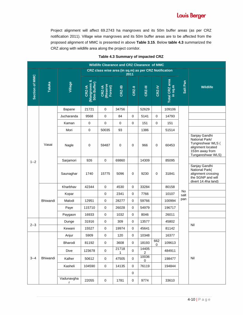
4-10 | P a g e
Project alignment will affect 69.2743 ha mangroves and its 50m buffer areas (as per CRZ
notification 2011). Village wise mangroves and its 50m buffer areas are to be affected from the
proposed alignment of MMC is presented in above Table 3.15. Below table 4.3 summarized the
CRZ along with wildlife area along the project corridor.
Table 4.3 Summary of impacted CRZ
Wildlife Clearance and CRZ Clearance of MMC
Se
cti
on
of
MM
C
Ta
luk
a
Vill
age
CRZ class wise area (in sq.m) as per CRZ Notification
2011
Sal
t P
an
Wildlife C
RZ
-IA
(M
an
gro
ve
s &
50
m B
uff
er)
CR
Z-I
A
(Re
se
rve
F
ore
st)
CR
Z-I
B
CR
Z-I
I
CR
Z-I
II
CR
Z-I
V
To
tal C
RZ
are
a in
sq
.m
1--2
Vasai
Bapane 21721 0 34756 52629 109106
No salt pan
Jucharanda 9568 0 84 0 5141 0 14793
Kaman 0 0 0 0 151 0 151
Mori 0 50035 93 1386 51514
Nagle 0 59487 0 0 966 0 60453
Sanjay Gandhi National Park/ Tungreshwar WLS ( alignment located 153m away from Tungareshwar WLS)
Sarjamori 926 0 69860 14309 85095
Saunaghar 1740 15775 5096 0 9230 0 31841
Sanjay Gandhi National Park( alignment crossing the SGNP and will divert 14.4ha land)
Bhiwandi
Kharbhav 42344 0 4530 0 33284 80158
Kopar 0 2341 0 7766 10107
Malodi 12951 0 28277 0 59766 100994
Paye 115710 0 26028 0 54979 196717
Paygaon 16933 0 1032 0 8046 26011
2--3 Dunge 31916 0 309 0 13577 45802
Nil Kewani 15527 0 19974 0 45641 81142
3--4 Bhiwandi
Anjur 5909 0 120 0 10348 16377
Nil
Bharodi 81192 0 3608 0 18193 6620
109613
Dive 123678 0 21718
1 0
144052
484911
Kalher 50612 0 47505 0 10036
0 198477
Kasheli 104590 0 14135 0 76119 194844
0
Vadunavghar
22055 0 1781 0 9774 33610

4-11 | P a g e
Wildlife Clearance and CRZ Clearance of MMC S
ecti
on
of
MM
C
Ta
luk
a
Vill
ag
e
CRZ class wise area (in sq.m) as per CRZ Notification 2011
Sa
lt P
an
Wildlife
CR
Z-I
A
(Man
gro
ves
&
50m
Bu
ffer
)
CR
Z-I
A
(Re
se
rve
F
ore
st)
CR
Z-I
B
CR
Z-I
I
CR
Z-I
II
CR
Z-I
V
To
tal C
RZ
are
a
in s
q.m
Kalyan Bhopar 35362 0 2236 0 49462 18567
105627
4--5 0 0 0 0 0 0 0
5--6 Thane
Belonda Khar
0 0 1187 8388 9575 Karnala Bird Sanctuary( 5813m away from alignment
Kauli 0 0 0 0 367 367
Conclusion 692734 12529
7 48013
3 0
723934
25187
2047285
No salt pan
Wildlife clearance proposal submitted to Wildlife Department. Now waiting for online submission of proposal on MOEF Website due to non-submission of online forest proposal waiting for online
4.1.9 Impact on Cultural Environment
There are no archeological monument exist within the 300m either side of the proposed corridor.
However, 7 cultural properties exist along the project corridor (Table 3.18 out of them 3 temple
will be impacted due to proposed MMC project.
4.2 IMPACT ON SOCIO -ECONOMIC ENVIRONMENT
The initial social assessment survey for the project corridor has been conducted to determine the
magnitude of actual and potential impact due to proposed corridor and to ensure that social
considerations has been given adequate weightage in the selection and design of proposed
alignment. Basic idea is to minimize adverse social impacts with best possible engineering
solutions at the optimal cost.
The present social impact assessment report of proposed alignment of MMC deals with the
several objectives related to social impact at this stage in accordance with the TOR.
The main objectives of this report is to delineate the major social impact issues, identify the
potential hotspots and determine the magnitude of actual and potential impacts. It also
recommends the cost-effective measures for minimizing the adverse social impacts. The main
features and findings of this report is as follows:
4.2.1 Scope and Objectives
The Social Assessment process generally begins with screening at the time of project
identification where steps are taken from the beginning and plans/ designs/ alignments are
finalized in such a way that to the extent possible adverse impacts are avoided at the designing
stage itself and make this project people friendly. These steps are:

4-12 | P a g e
Avoiding the adverse social impact at the designing stage especially while finalising the
alignments
Mitigating the adverse impacts at designing stage and construction /operation phase
Compensating the affected people/common properties and rehabilitation and resettlement
measures.
The overall objective of conducting Social Screening is to provide input of social concerns to be
dovetailed in the design and to avoid or minimize the adverse social impacts with the best
possible engineering solutions at the most optimal cost with complete co-ordination between the
engineering, environmental and social teams during the entire design process.
In brief, keeping in mind the scope and objectives of the study, the following main tasks has been
accomplished:
To highlight the need for a project;
To describe the proposed project and alternatives;
To evaluate the potential impacts of the project options on the valued ecosystem
components within the project study area;
To consult the local people, officials and experts on options and impacts in order to establish
institutional capacity;
To encourage the public participation during consultation;
To select the preferred project option and suggest mitigation plan.
4.2.2 Methodology
Social impact assessment need clear defination of the Corridor of Impact (CoI) and the Right of
Way (ROW) for establishing the extent of social impact. To achieve the target which needs
comprehensive data involves the following methodology:
Establishing the width that may include carriageway, shoulder, safety zone, borrowed areas,
etc. Determining the COI at the initial stage is important for undertaking social assessment
surveys within the defined area.
Collection of data from different agencies and sources which is already existing and
documented by them.
Thus, both primary and secondary data are required for establishing the extent of impact, which
need to be collected by administering the questionnaire for collecting information on structures,
properties, land and type of ownership and social groups etc. with the help of enumerators/
investigators and by collecting secondary data from different govt. and non- Govt. sources.
However, here the data has been collected on the basis of social survey and public consultation
as this study is restricted to only feasibility stage for which social screening survey, applying
rapid survey methods, has been conducted. The census and other related survey in details is
done only when the study require information at advance project level
The tabulated data has been summarized in tables and analyzed so that social situation

4-13 | P a g e
prevailing in the area is visualized and potential social issues are estimated. The analysis will
prove the feasibility of the project and will help in suggesting various socially viable alignment
options for engineering design and also come out with the mitigation measures to make the
project socio-economically acceptable.
The following steps have been followed in the social screening process adopted for the project:
Assessment of Socio-Economic Profile of the Project influence Area
Examination of Alignment Options
Social Screening & assessment of potential social impacts
Public Consultation
Analysis of alternatives
Identification of critical stretches
Preliminary budget for Social management
A brief discussion highlighting the methodology adopted to accomplish each of the above-
mentioned tasks is being presented in the following sub-sections.
4.2.3 Likely Loss of Properties
As per the Social Survey, it is estimated that as many as 516 existing properties are likely to be
affected by the proposed project within 99 meters ROW of the proposed carriageway. Land
Acquisition work is under progress and the actual impact will be updated on completion of LA
work. The details of properties are summarized in the Table: 4.4.
Table 4.4: Likely Loss of Properties in the Project Road
S. No. Type of Properties Total Percentage
1 Residential properties 394 76.36
2 Commercial properties 81 15.70
3 Industrial properties 14 2.71
4 Religious properties 3 0.58
4 Ponds/HP/TW 24 4.65
Total 516 100.00
Source: Social Survey
In terms of percentage, Residential property accounts 76.36%, Commercial 15.703%, Industrial
properties 2.71% and Utilities 4.65% % of all likely affected properties.
4.2.4 Type of Commercial Structures likely to be affected
There are 5 various types of commercial structures likely to be affected due to the proposed
project. As recorded in the primary data maximum numbers of commercial establishments
75.31%. The details of the commercial structures by the type of use are given in the Table 4.5.

4-14 | P a g e
Table 4.5: Type of Commercial Structures Likely to be affected
Sl. No. Type of Commercial Structures No. of
Structures Percentage
1 Commercial Building 61 75.31
2 Water park 1 1.23
3 Car Parking 1 1.23
4 Hotel/Dhaba 3 3.70
5 Logistic Yards 15 18.52
Total 81 100
Source: Social Survey
4.2.5 Loss of Land
Since, the proposed corridor required fresh alignment, the project would entail fresh land
acquisition of about 792 hectare for developing the proposed MMC Corridor. The additional land
would be required in around 42 villages of Palghar,Thane and Raigad districts. The proposed
land Acquisition will be made as per the “Right to Fair componsation and Transperancy in Land
Acquisiton, Rehabilitation and Ressettlement Act 2013” on this project. Since, Land Acquisition
work is in process, the accurate figure of LAvwill be updated on completeion of LA work. The
details of likely affected villages are given below.
Table 4.6: Village likely to be affected by Land Acquisition
Sr. No.
Village Sr.No Village Sl. No Village name
1 Barham Pur 16 Dongagaon 31 Motijhoni
2 Umelman 17 Kalwar 32 Digora
3 Navghar 18 Kasarvadoli 33 Saigaon
4 Rajoali 19 Anjur 34 Dapoli
5 Tihuri 20 Kopargaon 35 Dadar Para
6 Joochandra 21 Kalher 36 Dronagiri
7 Sarjja 22 Kehulidive 37 Navghar
8 Chandra
Para 23 Mankholi 38 Bhendghar
9 Khopari Parra
24 Balgaon 39 Kopta
10 Kamman
Road 25 Daptoa 40 Koproli
11 Silotar 26 Gundoli 41 Mothijuhi
12 Nagla 27 Allimghar 42 Chirner
13 Paya Gaon 28 Kolkhegaon
14 Kharbhav 29 Nadgaon
15 Barghar 30 Chindoli
Source: Social Survey
4-15 | P a g e
4.2.6 Impacted Persons
It is difficult to estimate the exact number of impacted person at this stage of the project.
However, estimated figure of impacted persons has been calculated on the basis of number of
structures likely to be affected and Land to be acquired as number of families multiplied by
district level household size i.e. 5.8 persons per family. Similary, 10 families per hectres on an
averages has been considered likely to be affected by the land acquisition. This will atleast give
some rough idea of the magnitude of impact. These figure will be updated on completion of LA
work. According to the primary survey there are about 48772 project-affected persons in 8409
families likely to be impacted directly or indirectly by the project. Details of estimated impacted
persons are given in the following Table 4.7.
Table 4.7: Preliminary Project Affected peoples
Type of affect Families Population
Male Female Total
Structures 489 1493 1343 2836
Land Acquisition 7920 24181 21755 45936
Total 8409 25674 23099 48772
Source: Social Survey
4.2.7 Vulnerable Households
Like project impacted persons, vulnerable persons impacted by the project has been estimated.
To arrive at this figure the district level SC and ST proportion has been considered as base. As
per 20011 census, project affected district having average 5.86% SC and 12.76% of ST of the
total population. The number of vulnerable families estimated as likely to be affected by this
project are 1740. The details of affected SC and ST population are given in following Table 4.8.
Table 4.8: Vulnerable Families/ Persons
S. No.
Category Families Persons
1 SC 493 2858
2 ST 1073 6223
Total 1740 10092
Source: Social Survey
4.2.8 Religious Properties
There are 3 religious structure are likely to be affected by the proposed alignment at this stage of
the project. All the likely affected structures are Temples.
4.2.9 Type of Utilities Likely To Be Affected
In the social survey the utilities have been enumerated, which reveals that there are 24 utilities
are likely to be affected. Out of which 11 are hand pumps, 1 tube wells and 12 pounds or ponds
like water bodies are likely to be affected. The details of utilities are summarized in the Table
below 4.9.
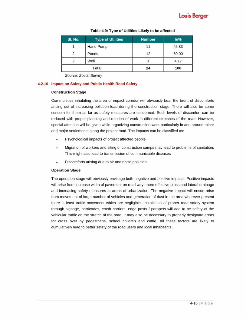
4-16 | P a g e
Table 4.9: Type of Utilities Likely to be affected
Sl. No. Type of Utilities Number In%
1 Hand Pump 11 45.83
2 Ponds 12 50.00
2 Well 1 4.17
Total 24 100
Source: Social Survey
4.2.10 Impact on Safety and Public Health Road Safety
Construction Stage
Communities inhabiting the area of impact corridor will obviously bear the brunt of discomforts
arising out of increasing pollution load during the construction stage. There will also be some
concern for them as far as safety measures are concerned. Such levels of discomfort can be
reduced with proper planning and rotation of work in different stretches of the road. However,
special attention will be given while organizing construction work particularly in and around minor
and major settlements along the project road. The impacts can be classified as:
Psychological impacts of project affected people
Migration of workers and siting of construction camps may lead to problems of sanitation.
This might also lead to transmission of communicable diseases
Discomforts arising due to air and noise pollution.
Operation Stage
The operation stage will obviously envisage both negative and positive impacts. Positive impacts
will arise from increase width of pavement on road way, more effective cross and lateral drainage
and increasing safety measures at areas of urbanization. The negative impact will ensue arise
from movement of large number of vehicles and generation of dust in the area wherever present
there is least traffic movement which are negligible. Installation of proper road safety system
through signage, barricades, crash barriers, edge posts / parapets will add to be safety of the
vehicular traffic on the stretch of the road. It may also be necessary to properly designate areas
for cross over by pedestrians, school children and cattle. All these factors are likely to
cumulatively lead to better safety of the road users and local inhabitants.

4-17 | P a g e
4.3 PART-2: MITIGATION, AVOIDANCE AND ENHANCEMENT MEASURES
4.3.1 Overview
Any infrastructure development work is likely to bring in both adverse and beneficial impacts on
biophysical, socio-cultural environment of a particular. It needs to be consciously pursued to
devise measures to mitigate adverse impacts if it is not possible to avoid it. Management
measures may to a great extent help in reducing the magnitude on such impacts and to keep
them at acceptable levels keeping in view the long term sustainable development of a region on
sound environmental considerations.
Multi Model Corridor projects particularly bring in adverse impacts on pollution load of different
environmental parameters like soil, water, air, noise, and ecological resources. There will also be
impact on the socio- economic parameters of the locality resulting in displacement / dislocation /
relocation for people and properties. This may also impact sensitive areas as far as conservation
of biological resources of a particular area is concerned. Cultural properties / heritage sites may
also be affected by such project execution. However, the impacts resulting from the project have
been discussed in details in the preceding chapter and the present chapter deals with mitigation,
management and enhancement measures of different components of the environment impacted
by this project.
4.3.2 Meteorological Parameters
Whatever the little impact will be on the climate at micro level will be mitigated by way of
compensatory afforestation on double the land to be diverted and new avenue plantations to be
done at the stretches where tree covers do not exist. The tree removal resulting in loss of shade
by road users is also a temporary negative impact; such impacts will disappear with the
restoration of vegetal cover over a much larger area.
Thus the proposed construction of MMC will be a relatively localized activity, which implies that
the road and rail development will not have any significant impact on climatic condition of the
project area.
The localized short-term adverse impacts will be offset by compensatory afforestation of
vegetation and tree plantation. No other specific mitigation measures are proposed for off-setting
adverse impacts on the climate in the project area.
4.3.3 Topography
Generally Embankment height will be raised from 4-5m all along the project corridor except at
location mentioned in Table 3.9 of chapter-3 where minor bridges and VUP or Flyover
proposed.
During construction phase following restrictions should be imposed to mitigate the impact on
topography:
i. Existing vegetation including shrubs and grasses along the route (except within the strip
directly under embankment or cutting) will be properly maintained during construction
phase,
4-18 | P a g e
ii. Quarrying, borrowing and disposal of spoils will conform to applicable laws and
regulations in India (including practice followed in recent/ongoing internationally funded
road projects in India)
iii. Any work in forest area will be carried after proper permission, and care should be taken
to avoid any impact on fauna.
iv. Cutting and felling will be balanced in Forest area.
4.3.4 Geology and Soil
The proposed project is not likely to have significant impact on the existing geology, hence no
mitigation measures have been proposed
4.3.4.1 Soil Erosion Control
For most of the project corridor stretches land level is plain/flat except where proposed alignment
passes through or close to hills.. This makes such slopes less vulnerable to rill and sheet
erosion. The problem of soil erosion during the construction stage is likely to be more
pronounced along bridge/VUP-end fills, over steep banks and embankment slopes. To check soil
erosion on critical road embankment slops turfing with shrubs and grasses will be carried out, in
accordance with the recommended practice for treatment of embankment slopes for erosion
control. Soil erosion checking measures as the formation of sediment basins, slope drains, etc.,
will be carried out at construction sites. Proper side drains for the storm water from the road will
be constructed so as to avoid pooling of water near toe line of the road and combination of water
bodies
Grass turfing of exposed slopes will also reduce possibilities of erosion. Construction of
embankments in bridge approaches may be organized in dry season to avoid erosion process
setting in high embankment on bridge approaches. Grass turfing will be taken up as practice
provided in IRC: 56-1974. Apron and approaches of bridges and cross drainage structures will be
paved with suitable paving materials for prevention of erosion during heavy rains.
Control of soil erosion will also include;
To place control measures in position for prevention of sedimentation by surface run-off
during the monsoon
Sitting storage yards of excavated materials with protection measure to prevent their
movement.
4.3.4.2 Soil Contamination
Such contamination may occur because of leakage of fuel, lubricants, waste oils, bitumen,
emulsion etc for the construction and allied activities but by nature this impact will be localized.
At the various construction sites, the vehicles and equipment will be maintained and refueled in
such a fashion that oil/diesel spillage does not contaminate the soil. It will be ensured that the
fuel storage and refueling sites are kept away from drainage channels and important water
bodies.
4-19 | P a g e
Construction Stage
Control measures will include:
Stripping and preservation of topsoil of Borrow areas, land acquired for temporary
diversion during construction,
Restricting the movement of Heavy machinery and construction vehicles on productive
land.
Refueling, Change of lubricants / oil and repairing to be carried at designated places
provided cemented platform and oil interceptors.
Construction of sump and provision of an impervious concrete base at all fuel, waste oil,
bitumen, emulsion etc storage yards
Use of non-toxic wastes in the project as far as possible
Measures for minimization of waste and proper collection, storage, of all solid and liquid
wastes generated
Provision of concrete platforms at parking bays
Construction of washing bays with interceptor and use of oil trays for collection of oil
spills during emergency repairs at site
Restoration of borrows areas and land used for temporary diversion by laying topsoil.
Operation Stage
Impacts are anticipated only in case of accidents involving large spills of hazardous materials
and petroleum products. This will require to be handled through the local authorities installed for
disaster management.
4.3.4.3 Compaction of Soil
To prevent the compaction of soil and the trampling of the vegetation around the construction
sites and temporary access roads, it will be ensured that the construction machinery and
equipment will move, or be stationed in the designated area. If the equipment and machinery are
operating on temporarily hired land, it will be ensured that the topsoil for agriculture remains
preserved and not destroyed by storage, material handling or any other construction related
activities. To minimize compaction of soil, all the vehicles will as far as possible, follow per-
designated routes.
4.3.4.4 Management of Soil Borrow Areas and Quarries
The quarry material will be obtained from licensed quarries, which operate with proper
environmental clearances, including clearance under the Air Act. If the contractors decide to use
quarries other quarries, they would be required to obtain material from licensed quarries only.
For the borrowing of earth for the project, borrow area locations will be identified and
recommended. However, in case of any new borrow area being selected by the contractor, it will
be ensured that no earth will be borrowed from within the ROW. If new borrow areas are
4-20 | P a g e
selected, it will be ensured by the contractor that, there will be no loss of productive soil, and that
the requisite environmental considerations are met with.
To avoid any embankment slippages, the borrow areas will not be dug continuously, and the size
and shape of borrow pits will be decided by the Supervision Consultants. The borrow pits will be
redeveloped, wherever required by creating ponds for fisheries, etc; or by leveling an elevated,
raised earth mound. If this is not possible, then excavation slopes will be smoothed and
depression will be filled in such a way that it looks more or less like the original ground surface.
Re-plantation of trees in borrows areas will also to be carried out, if required.
Precautionary measures as the covering of vehicles will be taken to avoid spillage during
transport of borrow materials. To ensure that the spills likely to result from the transport of borrow
and quarry materials do not impact the settlements, it will be ensured that the excavation and
carrying of earth will be done during day time only. The unpaved surfaces used for the haulage of
borrow materials will be maintained properly.
Mitigation for Quarries:
The following mitigation measures will be implemented.
Aggregates will be sourced only from the licensed quarry sites, complying with the
environmental and other applicable regulations,
Occupational Safety procedures/practices for the work force will be adhered in all
quarries as per law,
Quarry and crushing units will have adequate dust suppression measures like sprinkler
in work area and along approach road to quarry site,
Regular monitoring of the quarries by the supervision consultant to ensure compliances
of environmental management and monitoring,
Water tankers with suitable sprinkling system will be deployed along the haulage roads.
Water will be sprinkled regularly to suppress the airborne dust due to the dumper/truck
movement. Required frequency will be determined by the site condition.
Trucks deployed for the material transportation will be spillage proof.
Mitigation of Borrow Areas:
Impact due to borrowing soil can be significantly mitigated by the following measures:
Prior approval will be issued from the concerned authorities and all local environmental
regulations will be complied,
Within all identified borrow areas, the actual extent of area zones to be excavated will be
demarcated with signboards and the operational area will be access controlled,
Borrow operation plant and machineries will strictly conform to Central Pollution Control
Board (CPCB) noise standards;

4-21 | P a g e
Provision of protective wears like earplugs will be made available to the workforce
exposed to noise level beyond the threshold limits. Rotation of personnel will be
ensured.
All operation area will be water sprinkled to control dust levels to the National Ambient
Air Quality Standards.
Opening and management of borrow areas be done as per Guidelines 5 Borrow Area
Management and Clause 111 of Road and Bridge specification of MoRTH&CC. The borrow to
the extent possible will not opened in Agricultural field, In Right of way and loss of vegetation
should be minimum. Borrow areas should be rehabilitated as per agreement and in line with
measures detailed in Guidelines V for Borrow Area management.
4.3.4.5 Seismicity
Nature and magnitude of proposed work, does not create any seismicity hence no mitigation
measures required.
4.3.5 Loss of Agriculture Land
Proposed MMC project is passing through the cultivated land, low land, mangroves areas, and
forest and built up areas. Proposed MMC project will require 40 ha. Forest land and 752 hact
non forest land (LA work is in progress on completion of that work this figure will be updated).
The acquisition of agriculture land will result little impact on agricultural production of the project
area due to change in land use pattern. All the affected persons will be compensated as per the
persisting LA law.
4.3.6 Water Environment
4.3.6.1 Impact on Surface Water Bodies
The project involves construction of nine bridges on existing canals/Drain (refer Table 3.9 of
chapter-3) and one pond is located very near to the project road (Table 3.10 of chapter-3).
Potential mitigation measures to protect water quality will include:
Use of sediment traps and minimization of soil movement
Use of oil/ water separators to extract floating oils.
Channeling run-off with high level of suspended solids into sedimentation ponds.
Proper storage of contaminated liquids and disposal after treatment to bring such liquids
within prescribed permissible limits.
Turing with grass or planting with tress of all exposed areas as soon as possible to
reduce erosion risks.
Restricting construction activities near water bodies or canals as far possible during the
dry season.
On site fueling area of vehicles and equipments will be selected away from water bodies
and should be protected by a berm to prevent run-off leaving the area.
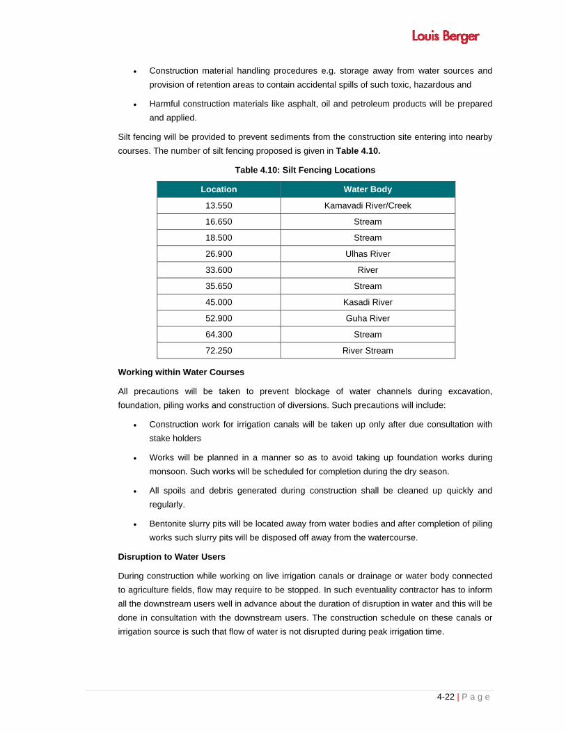
4-22 | P a g e
Construction material handling procedures e.g. storage away from water sources and
provision of retention areas to contain accidental spills of such toxic, hazardous and
Harmful construction materials like asphalt, oil and petroleum products will be prepared
and applied.
Silt fencing will be provided to prevent sediments from the construction site entering into nearby
courses. The number of silt fencing proposed is given in Table 4.10.
Table 4.10: Silt Fencing Locations
Location Water Body
13.550 Kamavadi River/Creek
16.650 Stream
18.500 Stream
26.900 Ulhas River
33.600 River
35.650 Stream
45.000 Kasadi River
52.900 Guha River
64.300 Stream
72.250 River Stream
Working within Water Courses
All precautions will be taken to prevent blockage of water channels during excavation,
foundation, piling works and construction of diversions. Such precautions will include:
Construction work for irrigation canals will be taken up only after due consultation with
stake holders
Works will be planned in a manner so as to avoid taking up foundation works during
monsoon. Such works will be scheduled for completion during the dry season.
All spoils and debris generated during construction shall be cleaned up quickly and
regularly.
Bentonite slurry pits will be located away from water bodies and after completion of piling
works such slurry pits will be disposed off away from the watercourse.
Disruption to Water Users
During construction while working on live irrigation canals or drainage or water body connected
to agriculture fields, flow may require to be stopped. In such eventuality contractor has to inform
all the downstream users well in advance about the duration of disruption in water and this will be
done in consultation with the downstream users. The construction schedule on these canals or
irrigation source is such that flow of water is not disrupted during peak irrigation time.

4-23 | P a g e
Ground Water Resources
1 wells and 11 hand pumps are recorded within the proposed project corridor which is going to
be impacted by the proposed activity. Corridor of Impact will be suitably compensated.
4.3.7 Air Environment
Pre Construction Stage
Some control measures have been built into the design phase. These measures will reduce
pollution load of suspended particulate matter in particular.
Construction Stage
The Construction activities are primary responsible for dust generation whereas the operation of
the plant and machineries are responsible for emission of gaseous pollutants. The dust
dispersion can be controlled through dust suppression methods of sprinkling of water at regular
intervals. As far as gaseous pollutants from construction plant and machinery are concerned, this
can be kept under control through a the adoption of following measures:
Vehicles delivering fine materials like soil and fine aggregates shall be covered to
avoid/reduce spills on existing roads.
Batch type hot mix plants fitted with the bag filter / cyclone and scrubber will be installed
for the reduction of the air pollution.
Pollution control systems like water sprinkling and dust extractors and cover on
conveyors will be installed for the crushers.
All vehicles, equipment and machinery used for construction will be regularly maintained
to ensure that the emission levels conform to the SPCB/CPCB norms.
Air pollution monitoring plan has been delineated for construction phase separately for
checking the effectiveness of the mitigation measures adopted during the construction
phase of the Contract.
Asphalt and hot mix plants will be located at least 1000 m away from settlements and
300m from the road.
Plantation of pollution resistant species like Azadirachta indicia, Ficus bengalensis, Albizzia
lebbek, Polyalthia longifolia etc while replacing the strip plantation may help in attenuating
pollution load of gases and particulate matter.
Operation Stage
Because of smooth traffic on improved surface roads the vehicular pollution is likely to improve.
However, such beneficial impact may also be negated by substantial rise in density of vehicular
traffic at this stage because of improved connectivity of the region and resulting induced
development. To minimize impact during this particular stage, it also will be necessary to avoid
ribbon development along the road stretch. Strict monitoring of emission norms of vehicles on
this road need be enforced for appreciation of the beneficial impact. Monitoring of the air pollution

4-24 | P a g e
levels has been proposed in this stage to keep pollution levels within the prescribed limits of
CPCB / SPCB.
Table 4.11 presents a comparative account of the sources of air pollution, their impact and
mitigation measures planned as given below.
Table 4.11: Sources of Air Pollution, Impacts and Suggested Mitigation Measures
Sl. No. Sources of Air
Pollution Impacts Suggested Mitigation Measures
1.
Cutting of slopes for construction of MMC;
Transportation and tipping of cut material;
Soil erosion Transportation
of raw materials from quarries and borrow sites;
Stone crushing, handling and storage of aggregates in the asphalt plants;
Site leveling, clearing of trees, laying of asphalt, construction of bridges;
Asphalt mix plants due to mixing of aggregates with bitumen
Generation of Dust (SPM)
To ensure that crushers, batching plants and asphalt plants all are located at a distance of 500 m away in the downwind direction from the nearest human settlement;
To ensure that all precautions shall be taken to reduce the level of dust emissions from crushers, batching and asphalt plants and from transportation of other materials;
Provision of wind breaking wall around the sources of dust such as vibrating screens, conveyors, etc. should be made and regularly checked for all stone crushers used to supply material for the project;
Vehicles delivering loose and fine materials like crusher dust and soil/spoils shall be covered to reduce spills on existing roads;
The hot mix plant will be fitted with dust extraction units;
Water will be sprayed on earthworks, temporary haulage and detour roads on a regular basis. During and after compaction of the sub-grade, water will be sprayed at regular intervals to prevent dust generation;
It shall be ensured that the dust emissions from the vibrating screen and crusher at the stone quarries do not exceed the emission standards set by CPCB; and
Monthly monitoring shall be conducted at locations where earthworks or slope cutting operations shall be conducted.
An adequate cyclone/scrubber to control emissions from the stock of hot mix plants will need to be provided in the event of emissions exceeding the CPCB norms;
2.
Hot mix plants; Large
construction equipment trucks and asphalt
Generation of polluting gases including SO2, NOx and HC
All vehicles, equipment and machinery used for construction work shall be regularly maintained to ensure that the pollution emission levels conform to the CPCB norms; and

4-25 | P a g e
Sl. No. Sources of Air
Pollution Impacts Suggested Mitigation Measures
producing and paving equipment;
Movement of heavy machinery, oil tankers etc. on steep lopes shall relatively contribute towards higher emissions of gases;
Toxic gases released through the heating process during bitumen
To ensure the efficiency of the mitigation measures suggested, air quality monitoring shall be carried out at least once a month at all these locations to check as to whether the emission levels are within the norms as prescribed by CPCB.
4.3.8 Noise Environment
Construction Stage
During construction stage, noise and vibration will be significant particularly in the busy
intersections and near settlements. Mitigation of disturbing noise level will be achieved through
following measures:
All construction equipments and vehicles should be maintained in good working
condition to keep their noise level within permissible limit of CPCB/ SPCB standards
Construction camp and temporary labour sheds will be located away from the vicinity of
construction site and major traffic areas.
Stationary construction equipments will be placed at a minimum distance of 300 m. from
settlements and silence zones.
Construction activities in settlements and near by areas will be scheduled to be carried
out during the hours of the day to cause minimum discomfort to community.
Operation Stage
With the improvement of road surface after rehabilitation noise level is likely to get attenuated in
the initial years after commission. But over a period of time the increased vehicular traffic along
the stretch of road may negate such beneficial impact. The proposed raising of tree cover along
the sides of road embankment and toe with the right mix of small, medium and tall trees is likely
to attenuate noise level to acceptable limits. Provisions have been made for monitoring of noise
level during operation stage to obtain a trend to enable the proponent organization to decide on
adoption of measures like erection of sound barriers particularly to protect silence zones and
sensitive receptors if dictated by such monitoring measures. A masonry noise barrier has been
proposed around a sensitive receptor to minimize the noise impact.

4-26 | P a g e
4.3.9 Construction Camp
The following criteria will guide the establishment of labour camps, offices and construction plat
sites:
These will be located at a distance of 1000m away from any major settlement or village
These will never be located at a distance of less than 1000m from surface water
sources.
Some principles as laid down here in below should be adhered to in management of these
camps:
Such camps should always be provided with a proper fence or a boundary wall.
There should be restriction on the movement of workers from the camps particularly
during the hours of the light.
Plant and machinery operation should be restricted between the hours of 6 am to 9 pm.
Under the proposed development the noise levels will be much more pronounced during
construction stage particularly around settlements and in inhabited areas. Mitigation measures as
listed in Table 4.12 shall therefore be adopted for mitigating noise levels.
Table 4.12: Sources of Noise Pollution, Impacts and Suggested Mitigation Measures
Source of Noise Pollution
Impacts Suggested Mitigation
Measures
Mobilization of heavy construction machinery; Acceleration/deceleration/gear changes by the vehicles depending on the level of congestion and smoothness of road surface; Excavation for foundations and grading of the site; Construction of structures and facilities; Crushing plants, asphalt production plants; and Loading, transportation and unloading of construction materials .
Increased Noise Levels causing discomfort to local residents and workers
All construction equipment, plants, machinery and vehicles will follow prescribed noise standards. All construction equipment used for an 8 hour shift shall conform to a standard of less than 90 dB (A); At construction sites within 150 m of human settlements, noisy construction shall be stopped between 10.00 PM and 6.00 AM; Vehicles and construction machinery shall be monitored regularly with particular attention to silencers and mufflers to maintain noise levels to minimum; Workers in the vicinity of high noise levels must wear ear plugs, helmets and should be engaged in diversified activities to prevent prolonged exposure to noise levels of more than 90 dB (A) per 8 hour shift; Hot mix plant, batching or aggregate plants shall not be located within 500 m of

4-27 | P a g e
Source of Noise Pollution
Impacts Suggested Mitigation
Measures sensitive land use as schools, hospitals etc; At critical locations, especially along sensitive receptors such as hospitals and schools, noise barrier walls and mounds of various materials such as earth, concrete, wood, metal or double glazing of windows for façade insulation shall be used.
4.3.10 Facilities at workers camps
Workers camps should be provided with facilities like sanitation, shelter, canteen, health care
and day crèche.
4.3.11 Ecology
Flora
The impact has been proposed to be mitigated through planting at least 3 times the number of
trees/mangroves removed or as per instruction of state forest department. This afforestation plan
will be drawn up and executed by state forest department. This department generally consults
stakeholders while deciding on the species mix and the pattern of planting in such afforestation
projects. Sprinkling of some fruit bearing and flowering species in this afforestation plan will
enrich this region with a variety of birds in addition to restoration of all associated benefits to the
community that were lost to them during construction stage through the removal of vegetal cover.
Local grasses, shrubs, and herbs will generally reappear in all blank/barren patches in the project
corridor during the operation stage, as most of these species are pioneer colonizing ones.
Fauna
Field indicates presence of wild animal near the project corridor. Wild animal like barking
dear, mouse dear, Langur, Monkey, Rabbit, Fox, and Neelgai and birds like Flycatcher,
Robin, Shama Magpie, the Malabar Whistling Thrush, Red Vented Bulbul, Myna, Horn
Bill,
Tungreshwar WLS(0.153km), Thane and Karnala Bird Sanctuary(5.183km), Riagd)
located within the 10km radius of the project road.
Proposed project MMC traverse through Sanjay Gandhi National Park and will divert
habitat of wild animals about 14.8 ha. Of N.P land
In vicinity of sanctuary area and in Sanjay Gandhi National park both side of the of the
project corridor will be well protect to avoid any direct contact with the wild life by
boundary wall or elevated corridor with view & noise protection or protection measure
shall be taken as advised by the Wildlife Department, Maharashtra.

4-28 | P a g e
Suitable no. of cross drainage structure/Wild Life/cattle underpass shall be provided for
easy movement of wildlife animals from one parts of the road/rail to other parts.
Road Safety signage like No pressure horn, Slow Drive, Wildlife Area shall be displayed
on the road.
Dense vegetation shall be grown within the ROW of bypasses to reduce the noise
intensity.
Eco sensitive Areas
Few km of proposed alignment of MMC passes through Matheran Eco sensitive areas and run in
close to the eco-sensitive zone. During construction phase no establishment of labour camp, Hot
mix plant, and quarry area selected in eco-sensitive zone.
Suitable no. of cross drainage structure/Wild Life/cattle underpass shall be provided for easy
movement of local wildlife animals from one parts of the road/rail to other parts.
Any activity will be carried in the Eco-sensitive zone after the permission from SPCB/MOEF.
Costal Regulation Zone Areas
Prior permission shall be obtained from the MOEF and State authority for the proposed work and
all the subjected measure will be followed during implementation of this project
4.3.12 Enhancement Measures
In accordance with EIA operative directives additional positive actions need be encouraged is a
part of EA process apart from remedial mitigation measures that have been proposed to adjust
the negative impact during the project. Such environment enhancements are undertaken with the
specific purpose of giving benefits to the road users and communities living along the MMC
project. Such gestures bring a lot of goodwill from the local communities and this helps to rally
support of the stakeholders in execution of the project in the fixed time frame.
4.3.12.1 Objectives
Following are the objectives of the environmental enhancement measures:
To enhance the environmental quality of the project corridor to its users,
To enhance visual quality along the corridor, and
To generate goodwill among the local community towards the project, by the
enhancement of common property resources.
The various enhancement measures proposed for the MMC project include:
Enhancement of road-side facilities viz. bus bays, truck terminals, junction development
etc.
Improvement of aesthetic qualities of the project (landscaping, selective tree plantation)
and plantation of bushes in median.
Management of existing problems (lack of shade to the slow moving traffic);
Landscaping along the project corridor;

4-29 | P a g e
Improvement of the natural resources for the local population (provision of fodder, fuel
wood, etc. by careful selection of species to be planted along the road if land is
available) and,
The proposed enhancement measures are described in the following sections.
4.3.13 Natural Environment
4.3.13.1 Landscaping
Project road will be landscaped by using various techniques of soft landscapes, principally
through planting of various types of trees. Proposed plant can be categorized into trees, shrubs,
and ground covers.
4.3.13.2 Tree Plantation Schemes
Some basic norms to be followed in tree plantation scheme are:
1. Pure avenues plantation with single species (only to be) planted for a number of
kilometers (the stretch between two market places) provide harmonious and pleasing
look, and a regular and wavelike skyline. This row of trees forms the first and innermost
line.
2. There is a remarkable coordination between the topography, shape of tree and sky.
Accordingly the umbrella-like acacias and Gulmohars and semi-umbrella like Neem,
Shisham, and Arjun are admirably suited to the flat nature of the country.
3. Selections of tree species in outer rows (where multiple rows are to be grown) were
considered from economic point of view. Therefore, trees that provide fuel and fruit as
well as small timber for agricultural implements have been suggested. Some fuel and
small timber producing trees include babul, acacia; the fruit producing trees are varieties
of Mango,
4. The plantation of trees according to different densities may be:
Replantation: trees having girth less than 900mm.
Sparse plantation: one linear row of trees plantation
Medium density plantation: Two rows of tree plantation with the flowering shrub
plantation
Dense plantation: More than two rows of tree plantation with dense shrubs.
4.3.13.3 Criteria for selection of tree species
The planting type was decided based on their requirement and feasibility at various sites along
the project corridors. Physical growth characteristics of trees, like form and shape, foliage and
rooting characteristics, growth rate, canopy type and branching pattern were the major criteria in
the selection of plantation type and density. From climatologically point of view, elimination of
solar glare during low elevations of the sun was considered in the design decisions. Water table
depths helped in the choice of plant material from the point of their survival rate after plantation.
In a tropical country like India, where the temperature during summer months may rise up to a
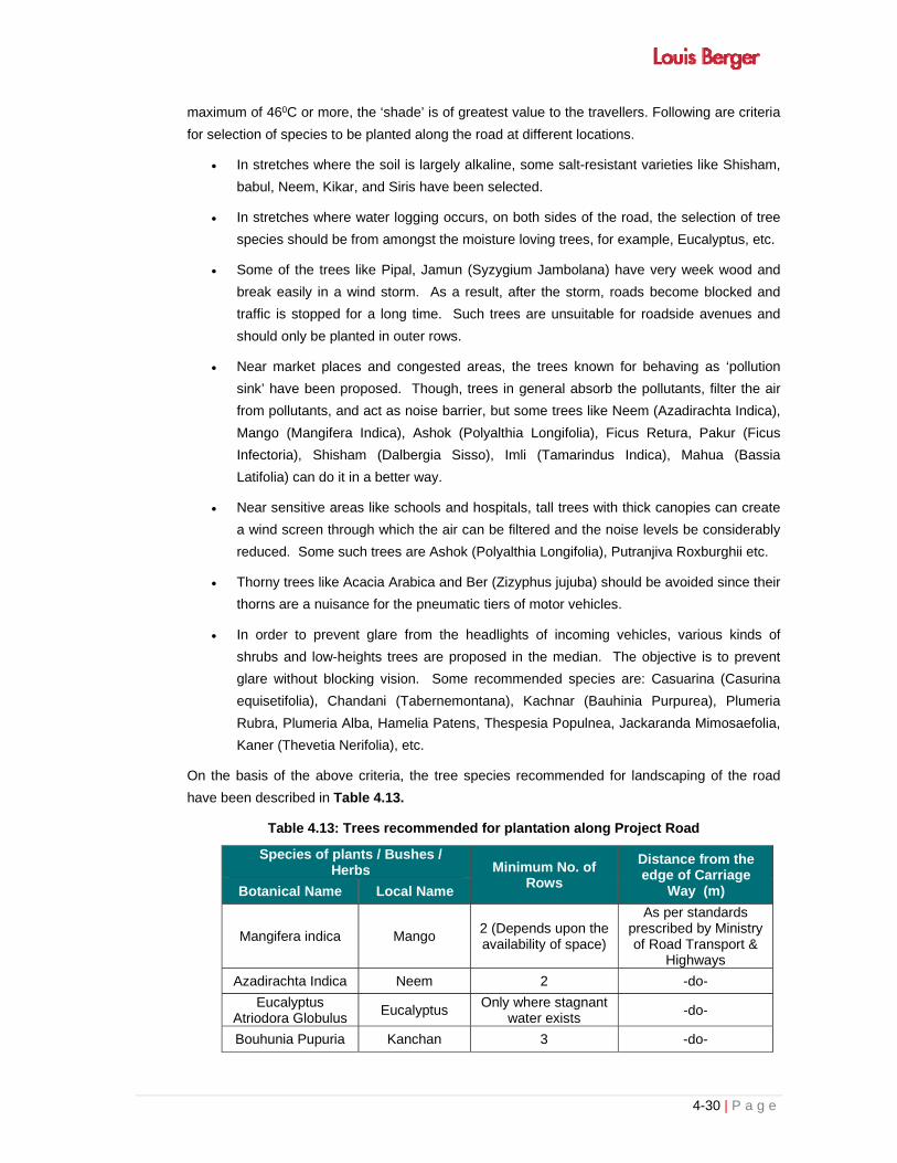
4-30 | P a g e
maximum of 460C or more, the ‘shade’ is of greatest value to the travellers. Following are criteria
for selection of species to be planted along the road at different locations.
In stretches where the soil is largely alkaline, some salt-resistant varieties like Shisham,
babul, Neem, Kikar, and Siris have been selected.
In stretches where water logging occurs, on both sides of the road, the selection of tree
species should be from amongst the moisture loving trees, for example, Eucalyptus, etc.
Some of the trees like Pipal, Jamun (Syzygium Jambolana) have very week wood and
break easily in a wind storm. As a result, after the storm, roads become blocked and
traffic is stopped for a long time. Such trees are unsuitable for roadside avenues and
should only be planted in outer rows.
Near market places and congested areas, the trees known for behaving as ‘pollution
sink’ have been proposed. Though, trees in general absorb the pollutants, filter the air
from pollutants, and act as noise barrier, but some trees like Neem (Azadirachta Indica),
Mango (Mangifera Indica), Ashok (Polyalthia Longifolia), Ficus Retura, Pakur (Ficus
Infectoria), Shisham (Dalbergia Sisso), Imli (Tamarindus Indica), Mahua (Bassia
Latifolia) can do it in a better way.
Near sensitive areas like schools and hospitals, tall trees with thick canopies can create
a wind screen through which the air can be filtered and the noise levels be considerably
reduced. Some such trees are Ashok (Polyalthia Longifolia), Putranjiva Roxburghii etc.
Thorny trees like Acacia Arabica and Ber (Zizyphus jujuba) should be avoided since their
thorns are a nuisance for the pneumatic tiers of motor vehicles.
In order to prevent glare from the headlights of incoming vehicles, various kinds of
shrubs and low-heights trees are proposed in the median. The objective is to prevent
glare without blocking vision. Some recommended species are: Casuarina (Casurina
equisetifolia), Chandani (Tabernemontana), Kachnar (Bauhinia Purpurea), Plumeria
Rubra, Plumeria Alba, Hamelia Patens, Thespesia Populnea, Jackaranda Mimosaefolia,
Kaner (Thevetia Nerifolia), etc.
On the basis of the above criteria, the tree species recommended for landscaping of the road
have been described in Table 4.13.
Table 4.13: Trees recommended for plantation along Project Road
Species of plants / Bushes / Herbs Minimum No. of
Rows
Distance from the edge of Carriage
Way (m) Botanical Name Local Name
Mangifera indica Mango 2 (Depends upon the availability of space)
As per standards prescribed by Ministry of Road Transport &
Highways
Azadirachta Indica Neem 2 -do-
Eucalyptus Atriodora Globulus
Eucalyptus Only where stagnant
water exists -do-
Bouhunia Pupuria Kanchan 3 -do-

4-31 | P a g e
Species of plants / Bushes / Herbs Minimum No. of
Rows
Distance from the edge of Carriage
Way (m) Botanical Name Local Name
Tamarindus indica Imli 2 -do-
Ficus Bengalensis Bargad 2 -do-
Delonix regia Gulmohar 2 -do-
Dalbergia sisso Shisham 2 -do-
Ficus religiosa Pipal 2 -do-
Acacia arabica Babul 3 -do-
Bauhinia Variegata Kachnar 2 -do-
Under Growth and Edges along Clear Zone
The clear zone along various corridors is of varied nature depending upon the different
embankment heights. Some areas have slight gradients that need intensive stone pitching
treatment. In order to increase the structural stability of this type of treatments, plant materials
such as shrubs and ground covers have been introduced in the interstices. They have been
used with emphasis on their rooting characteristics so that they help in binding the stone pitching
treatments. In areas of high water table or water logging, special emphasis has been given on
the selection of plant materials that can survive in moist conditions.
Developing herbal cover and turfing with grasses reduces the degree of soil erosion. The most
important grasses recommended at the outmost boundary of the RoW include Khas, Kans and
Sarpat. The Khas has an added advantage since its roots produce the scented oil used in
perfumeries. Small cottage industries of perfumery can be developed in certain areas if such
planting is carefully implemented
4.3.14 Road Safety
Design Stage
Safety of road users, particularly pedestrians, given due consideration at this particular stage.
Both sides of the MMC will have pavements for use by pedestrians. In addition to this keeping
view the safety of vehicular traffic on approaches to bridges the road is being constructed into
5x5lane with rail.
Construction Stage
For provision of required safety precaution traffic management plan will be prepared and
implemented during construction in accordance of IRC: SP: 55 (Guidelines on Safety in Road
Construction Zones). During the process of construction bridges over the canals appropriate
route diversion signage and management of traffic detours will be implemented.
4.3.14.1 Health/ Safety Measures for Labours
First Aid boxes with first aid leaflets will be placed at all work places and at least four sets in the
each construction camp. Some of the workers will be given first aid training to treat some of the
emergencies at the working zones and at auxiliary sites. Arrangements with nearby health
centers and local doctors will be made for treating injuries, which needs attention of specialist
4-32 | P a g e
doctors. During the construction phase, workers will be provided personal protective equipment
based on the nature of the work. Personal protective equipment will include:
Safety glasses for protection of eyes
Face Shields and Masks for protection of face and nose
Helmets and Safety shoes for protection of Head and Feet
Gloves, Vests and Earplugs for protection of Hand/Arms, Bodies and Hearing
4.3.14.2 Traffic Safety Plans
Design Stage
If required, service road will be provided along the road to segregate the local traffic from the
project road.
Construction Stage
All required safety precautions and traffic management plans will be prepared and implemented
during construction in accordance with the IRC: SP: 55 (Guidelines of Safety in road construction
zones) will be followed. There will be conscious effort to ensure that the road users and the
communities near the work site suffer minimal discomfort during the construction phase of
different stretches of the road. A suitable Traffic Management Plan will be prepared especially for
construction sites and bridge locations and their approaches.
4.3.15 Cultural Environment
The proposed construction of MMC project will involve relocation of 7 cultural properties (refer
Annexure3.18). The cost of such relocation has been provided for in the RAP. The impact of
private property is very minimal and a suitable compensation package has been designed in the
RAP to compensate for the loss / relocation of such properties. As far as the Project Affected
Households and the Project Affected Families are concerned, a suitable package for
compensating their losses has been provided in the Resettlement Action Plan (RAP).
4.3.16 R&R and Land Acquisition Cost
R&R-cum-Land Acquisition cost would only be work out on receive of Actual Land Acquisition
(Private) data along with their classification and approved entitlement matrix. It is pertain to
mention that to work out the actual R&R cost it is mandatory to know the actual impact on likely
affected properties to know the displacement and survival ratio of structures in post project
scenario. The Land acquisition is under progress by the consultant hired by the MMRDA and on
completion of work detailed R&R Cost will be prepare on the basis of approved entitle matrix.
The project MMC will in general have beneficial impact on socio- economic front both locally and
regionally through improved better and safer connectivity of the project area with markets located
in the state adjoining areas. But there will be also some adverse impacts resulting from
i. Resettlement of People
ii. Relocation of community structures
iii. Acquisition of land and structures

4-33 | P a g e
iv. Influx of Construction Workers
4.3.17 Institutional Arrangement
4.3.17.1 General
The Monitoring and Evaluation are critical activities in implementation of the Project. Monitoring
involves periodic checking to ascertain whether activities are going according to plan or not. It
provides the necessary feedback for project management to ensure project objectives are met
and on schedule. The reporting system is based on accountability to ensure that the
Environmental Management Plan is implemented.
This chapter summarizes the institutional arrangements, reporting system arrangements and
training details for the implementation of the environmental management plan.
4.3.17.2 Existing Institutional Arrangements
Existing Institutional Capacity in MMRDA
The Mumbai Metropolitan Regional Development Authority (MMRDA), a nodal agency for
development of infrastructure projects in the in the Mumbai Area. On behalf of Government of
Maharashtra, MMRRDA is entrusted to develop MMC from Navghar to Chirner. The project will
be either by EPC or Public Private Partnership (PPP) venture pattern.
The Chief Engineer, MMRDA will responsible for the successful implementation of the Project.
Executive Engineers and his supporting staff as Employers representatives nominated for the
project are responsible for the implementation of the Projects under his division.


i | P a g e
TABLE OF CONTENTS
CHAPTER - 5: ANALYSIS OF ALTERNATIVES .................................................................................. 5-1
5.1 LONG TERM SCENARIO “WITH” AND “WITHOUT” PROJECT .............................................. 5-1
5.2 OVERALL ANALYSIS OF PROJECT IMPACT ......................................................................... 5-3
5.3 ALTERNATIVE METHODS OF CONSTRUCTION ................................................................... 5-4
5.3.1 Alignment selection ...................................................................................................... 5-7
LIST OF TABLES
Table 5.1: “With” and “Without” Project Scenarios. ................................................................................ 5-1
Table 5.2: Quantitative analysis of overall project impact ...................................................................... 5-6
Table 5.3: Cost Comparison with Merits and Demerits of Three Alternatives ........................................ 5-8


5-1 | P a g e
CHAPTER - 5: ANALYSIS OF ALTERNATIVES
The analysis of alternative is a documented illustration/evidence to show and ensure that final
decisions taken are;
In accordance with the project objectives
In compliance with the country laws, policies and legal requirements
To confirm that the project is actually needed and not imposed on the State
Not to lead any major loss or destruction to natural resources either directly or indirectly
To confirm that the implementation of the project will not lead to any major crisis or conflict in
the community during construction phase
To confirm that the Public/Government financial resources are not worn out for wrong
projects/infrastructural works without the consideration of views of the stakeholders
To confirm that no individual and biased approach (for example implementation of a personal
ambition using public money in a secretive manner) from the responsible implementing
official/s has taken place
In accordance with the actual requirements of the country and people.
In sub-sequence section, analysis of alternatives for the project is discussed. The section begins
with an analysis of the likely resulting scenario “with” and “without” the project. This is based on
a quantitative analysis of overall impacts using the Delphi Technique. Various engineering
alternatives for the methods of construction are then considered – this involves analysis of the
environmental, social, engineering, economic and institutional implications of each option.
5.1 LONG TERM SCENARIO “WITH” AND “WITHOUT” PROJECT
Qualitative analysis of the long-term scenarios likely to occur “with” and “without” project scenario
is provided in Table 5.1. The “with” project scenarios will, however, only occur only if the
recommendations provided in Chapter 4 for the construction stage are followed and all
construction activities are carried out according to principles of Environment Friendly Road
Construction..
Table 5.1: “With” and “Without” Project Scenarios.
Scenario type Long-Term Scenario “With” Project Long-Term Scenario
“Without” Project
Environment
Physical Environment
Atmosphere and Climate
Travel time and traffic congestion will reduce as a result of 4-laning of highway. Overall, a lower or similar level of air pollution. No change in climatic condition
Congested road will consume more travel time and will increase air pollution. No change in climatic condition
Topography and Soils
Significant change in topography and no impact on existing soil conditions, however, better road will reduce soil erosion and dust Landscaping along the highway will also enhance the esthetic beauty of the area
As it is

5-2 | P a g e
Scenario type Long-Term Scenario “With” Project Long-Term Scenario
“Without” Project
Geology and Seismology
No Impact
No change and possibly some deterioration in problems due to naturally weak geological conditions.
Water Bodies and Drainage
Improved drainage due to improvement in drainage structures and facilities
No changes in present problems associated with inadequate drainage.
Ecological Environment
Flora
About 1200 trees and plants exist in proposed ROW of project corridor which are going to be affected by the proposed activity. It will change the micro level environment of the area. However, through compensatory afforestation @ 1:3or as per the instruction of the forest department will again improve the greenery of the area but it will take some time. 14.8 ha land and 5135 trees going to be affected in SGNP.
No change in vegetation and number of trees.
No change in present land use
Fauna
Increase disturbance and chances of illegal hunting during construction period which will be minimized by the patrolling of forest department proposed MMC construction. After construction of MMC side fencing/netting will be carried out in National Park area which will improve positively.
Continued, and possibly increased disturbance to the fauna. Increased disturbance and chances of illegal hunting due to overall traffic growth on existing roads.
CRZ Some mangrove are going to be affected No change
Agricultural Land
About 725ha agricultural land will be involved for the proposed project MMC.
No change in present land use
Social and Cultural Environment
Social and Cultural
Environment
Increased comfort and safety while traveling. Improved business environment for those living along the project road-increased passing trade from generated traffic and reduced transportation costs for imports and exports of the area.
Traveling may increase time, thereby transportation costs will increase. Reductions in comfort and safety due to congestion and deterioration in highway condition. Business opportunities remain largely the same as before.
Connectivity Improve the connectivity between various proposed growth center
No change
Institutional Requirements
Training of PIU
Training will need to be provided to relevant PIU officials to improve their environmental monitoring capacity during and after project construction. More staff will need to be recruited at the PIU office to enable smooth flow of all paperwork with regard to implementation of environmental policies and regulations.
No institutional strengthening is required.
Economic Situation

5-3 | P a g e
Scenario type Long-Term Scenario “With” Project Long-Term Scenario
“Without” Project
Financial Implications
Higher capital costs for using Environmental Friendly techniques for proposed MMC. Costs will also be incurred for training of PIU officials. Lower vehicle operating costs associated with smoother riding surfaces and shorter travel times.
No capital costs. However, increasing road maintenance and vehicle operating costs as road deteriorates and as travel times increase.
Induced development
Surrounding the project induced development will take place
No chage
Overall
Long term improved social and environmental conditions but an increase in expenses for project activities during the course of project construction.
Small deteriorations in environmental conditions, no increase in economic opportunities and increased expenses associated with maintenance.
The project should lead to an overall improvement in environmental and social conditions. It is,
nevertheless important to use environmentally friendly road construction techniques.
5.2 OVERALL ANALYSIS OF PROJECT IMPACT
A quantitative analysis of the impact of all construction activities on various environmental, social,
institutional and economic factors is provided in matrix format in Table 5.2. A quantitative
estimate of overall total impact is also provided.
Various environmental, social, institutional and economic parameters are weighted as to their
perceived importance and within a total of 1,000. The weights are professional judgments
concerning: (i) the importance of baseline conditions; and (ii) the factors themselves.
Scores ranging from -5 to 0 to 5 were given to the presumed level of impact from each of nine
construction activities and an average calculated. A positive number indicates a positive impact
and a negative number, a negative impact – “0” indicates no impact. The criteria for awarding
scores are expanded below:
Score1 Level of Impact
5 Permanent positive impact
4 Major long term positive impacts
3 Significant positive impacts
2 Short term positive impacts
1 Minimal positive impacts
0 No impact
-1 Minimal negative impacts
-2 Significant reversible short term impacts
-3 Significant irreversible impacts
1 The Delphi Technique was used assign the scores relating to the likely impact of each parameter on each category of activity. The Delphi Technique is a process of refining the opinions of a group of people, who are representative of various disciplines, background and/or different points of view. The Delphi process is the synthesis of professional judgment and an interactive way of determining the impact of project activities.

5-4 | P a g e
-4 Major long term reversible impacts
-5 Permanent negative impact
The “Total Impact Score” = “Weightage Applied to Each Factor” x “Average Score against
Each Construction Activity”
Different overall “Total Impact Scores” may be deemed to imply the following and to lead to the
recommendations alongside:
> 400 Permanent positive impacts. Project highly recommended.
300 – 400 Major long term positive Impacts. Project highly recommended.
200 – 300 Long and short term positive impacts and negative but reversible
impacts. Control measures are needed. Project recommended.
100 – 200 significant positive impacts and mostly reversible negative impacts.
0 – 100 Positive and negative impacts closely balanced – an alternate project
site might be considered.
-ve Positive and negative impacts closely balanced - permanent irreversible
negative impacts may be occurring and an alternative project may need
to be considered.
The overall total impact score for the project MMC is 123.3 and the project might, thus, be
characterized as having, generally significant, positive and, mostly reversible, negative impacts.
The project is recommended but the adoption of mitigation measures is crucial in order to avoid
adverse negative impacts.
5.3 ALTERNATIVE METHODS OF CONSTRUCTION
All methods except those involving heating with firewood are acceptable. However the quality of
work should be good. Seepage of water through the pavement and causing damage to the
underlying base courses needs to be prevented. Such will cause a rapid deterioration in
structural strength and riding quality, resulting in higher vehicle operating costs, longer travel
times and more emissions. Bitumen emulsion should be used wherever possible
The key recommendations for each type of engineering or construction parameter are:
1. Pavement:
- Use paving methods and bitumen types according to economic and engineering needs and
the engineering suitability of the road.
- All methods of paving, except those involving heating with firewood, are acceptable.
However the quality of work should be good. Seepage of water through the pavement and
causing damage to the underlying base courses needs to be prevented. Such will cause a
rapid deterioration in structural strength and riding quality, resulting in higher vehicle
operating costs, longer travel times and more emissions. Bitumen emulsion should be used
wherever possible.
- Detailed design engineers, supervisory engineers and contractors should be aware of, or

5-5 | P a g e
made aware of, the suitability of each method of pavement construction and the behaviour of
different types of bitumen under varying climatic, traffic and other road conditions.
2. Highway Side Drainage and Drain Alternative
The road side drainage is ensured by three alternatives/forms, these are decided keeping in
view of the land use along the corridors, economical aspects for the over all project cost, the
three types of drain that was used was as follows:
i) Trapezoidal Drain
This drain section is used in plain and or flat areas where the embankment heights are
shallow; this drain is normally unlined and would require regular maintenance by means of
cleaning regularly.
ii) V-Shaped Drain
This drain is provided normally in the cut slopes located in hilly and rolling terrain, this drain
is of lined in nature. Predominant lengths in hilly areas are provided with this type of drain.
iii) Covered Drain
The locations, which are highly built up and it has been anticipated with pedestrian
movements; covered drains with side walk has been proposed. In the locations where the
drains out lets are not available the covered footpath with side walk has been proposed.
Construction option
- Drains lined with cement mortar should be used. This will minimise damage to the road
from leakages and should minimise total costs.
- Cross drainage structures should be designed to accommodate and support the
expected water flows.
3. Way Side Amenities-Alternative
The consultants have studied requirement of various way side amenities which includes the
following:
Bus bays
Rain Shelter
Parking Areas
4. Retaining Wall Location
Based on the designed alignment and on the basis of the topographic surveys results, with
the location where the normal hill slopes can not be used due to the topographic conditions,
consultants have adopted the retaining wall alternative. Normally the Stone Masonry with
Plum concrete was used for the retaining wall as it is being practiced in the various States.

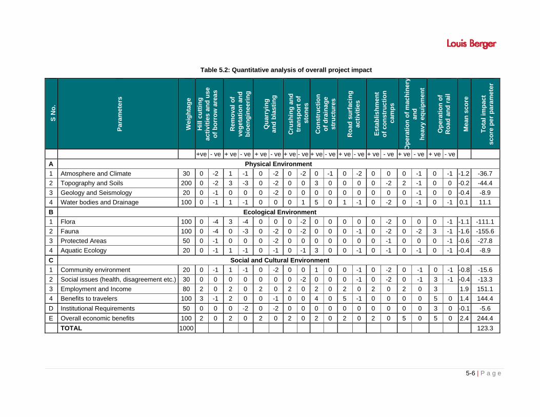
5-6 | P a g e
Table 5.2: Quantitative analysis of overall project impact
S N
o.
Par
amet
ers
Wei
gh
tag
e
Hil
l cu
ttin
g
acti
viti
es a
nd
use
o
f b
orr
ow
are
as
Rem
ova
l o
f
veg
etat
ion
an
d
bio
eng
inee
rin
g
Qu
arry
ing
an
d b
last
ing
Cru
shin
g a
nd
tr
ansp
ort
of
sto
nes
Co
nst
ruct
ion
o
f d
rain
age
st
ruct
ure
s
Ro
ad s
urf
acin
g
acti
viti
es
Est
abli
shm
ent
o
f co
nst
ruct
ion
c
amp
s
Op
erat
ion
of
mac
hin
ery
and
h
eav
y eq
uip
men
t
Op
erat
ion
of
R
oad
an
d r
ail
Mea
n s
core
To
tal
imp
act
sc
ore
per
par
amet
er
+ve - ve + ve - ve + ve - ve + ve - ve + ve - ve + ve - ve + ve - ve + ve - ve + ve - ve
A Physical Environment
1 Atmosphere and Climate 30 0 -2 1 -1 0 -2 0 -2 0 -1 0 -2 0 0 0 -1 0 -1 -1.2 -36.7
2 Topography and Soils 200 0 -2 3 -3 0 -2 0 0 3 0 0 0 0 -2 2 -1 0 0 -0.2 -44.4
3 Geology and Seismology 20 0 -1 0 0 0 -2 0 0 0 0 0 0 0 0 0 -1 0 0 -0.4 -8.9
4 Water bodies and Drainage 100 0 -1 1 -1 0 0 0 1 5 0 1 -1 0 -2 0 -1 0 -1 0.1 11.1
B Ecological Environment
1 Flora 100 0 -4 3 -4 0 0 0 -2 0 0 0 0 0 -2 0 0 0 -1 -1.1 -111.1
2 Fauna 100 0 -4 0 -3 0 -2 0 -2 0 0 0 -1 0 -2 0 -2 3 -1 -1.6 -155.6
3 Protected Areas 50 0 -1 0 0 0 -2 0 0 0 0 0 0 0 -1 0 0 0 -1 -0.6 -27.8
4 Aquatic Ecology 20 0 -1 1 -1 0 -1 0 -1 3 0 0 -1 0 -1 0 -1 0 -1 -0.4 -8.9
C Social and Cultural Environment
1 Community environment 20 0 -1 1 -1 0 -2 0 0 1 0 0 -1 0 -2 0 -1 0 -1 -0.8 -15.6
2 Social issues (health, disagreement etc.) 30 0 0 0 0 0 0 0 -2 0 0 0 -1 0 -2 0 -1 3 -1 -0.4 -13.3
3 Employment and Income 80 2 0 2 0 2 0 2 0 2 0 2 0 2 0 2 0 3 1.9 151.1
4 Benefits to travelers 100 3 -1 2 0 0 -1 0 0 4 0 5 -1 0 0 0 0 5 0 1.4 144.4
D Institutional Requirements 50 0 0 0 -2 0 -2 0 0 0 0 0 0 0 0 0 0 3 0 -0.1 -5.6
E Overall economic benefits 100 2 0 2 0 2 0 2 0 2 0 2 0 2 0 5 0 5 0 2.4 244.4
TOTAL 1000 123.3


5-7 | P a g e
5.3.1 Alignment selection
Alignment selection was carried out on the basis of evaluation of various alternatives for each
option. Both qualitatively and quantitatively evaluation has been done for various factors
influencing the selection process. These factors can be broadly grouped under main heads
such as geometrics, cost, economic benefits and social and environmental impacts. The
qualitative evaluation rates the alternative as less desirable, desirable, more desirable and
most desirable against each factor. The factors that were considered for qualitative
comparison are:
(i) Land availability.
(ii) Effect on residential/commercial buildings.
(iii) Ponds affected.
(iv) Religious structures affected.
(v) Flora and fauna affected.
(vi) Long term utility.
(vii) Environmental Quality.
(viii) Ecological sensitive area (WL/NP/ESZ/BS/RF/PF/CRZ)
(ix) Critically notified polluted area
Similarly quantitative evaluation was done for the following factors:
i) Route length.
ii) Number of sharp horizontal curves.
iii) Length of agricultural land affected.
iv) Length of barren land affected.
v) Length of residential land affected.
vi) Length of commercial land affected.
vii) Number of road crossings.
viii) Number of river/canal crossings.
ix) Pucca / Kutcha - commercial / residential structures affected.
x) Telephone/Electric poles to be shifted.
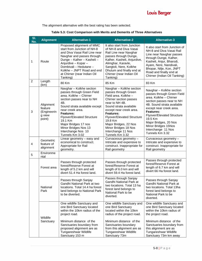
5-8 | P a g e
The alignment alternative with the best rating has been selected.
Table 5.3: Cost Comparison with Merits and Demerits of Three Alternatives
Sl. No.
Alignment Alternative-1 Alternative-2 Alternative-3
1 Route
Proposed alignment of MMC start from Junction of NH-8 and Diva Vasai Rail Line near Navghar and passes through Dunge – Kalher – Kasheli – Anjurdive – Kopar – Dombivali – Hedutane – Kolkhe – JNPT Road and end at Chirner (near Indian Oil Tanking)
It also start from Junction of NH-8 and Diva Vasai Rail Line near Navghar passes through Dunge, Kalher, Kasheli, Anjurdive, Alimghar, Karavle, Sangtoli, Nere, Kolkhe Dhutum and finally end at Chirner (near Indian Oil Tanking)
It also start from Junction of NH-8 and Diva Vasai Rail Line near Navghar passes through Dunge, Kalher, Kasheli, Anjur, Bharodi, Ayare, Nere, Nandivali, Bhopar, Nilje, Kon, JNPT Road and finally end at Chirner (Indian Oil Tanking)
2
Length (km)
80 Km 85 Km 83 Km
3
Alignment feature (Engineering view point)
Navghar – Kolkhe section passes through Green Field area. Kolkhe – Chirner section passes near to NH 4B. Sound strata available except near creek area. Features: Flyover/Elevated Structure 19.1 Km Major Bridges 17 nos Minor Bridges Nos 13 Interchange Nos 10 Tunnels Km 3.02
Navghar – Kolkhe section passes through Green Field area. Kolkhe – Chirner section passes near to NH 4B. Sound strata available except near creek area. Features: Flyover/Elevated Structure 19.8 Km Major Bridges, 22 Nos Minor Bridges 18 Nos Interchange 11 Nos Tunnels Km 3.32
Navghar – Kolkhe section passes through Green Field area. Kolkhe – Chirner section passes near to NH 4B. Sound strata available except near creek area. Features: Flyover/Elevated Structure 19.5 Km Major Bridges, 20 Nos Minor Bridges 15Nos Interchange 11 Nos Tunnels Km 3.32
4 Geometric feature of alignment
Linear geometry – easy and economical to construct. Appropriate for Rail geometry.
Curvaceous geometry – Intricate and expensive to construct. Inappropriate for Rail geometry
Curvaceous geometry – Intricate and expensive to construct. Inappropriate for Rail geometry
5 Environmental
Forest area
Passes through protected forest/Reserve Forest at length of 5.2 km and will divert 51.4 Ha forest land.
Passes through protected forest/Reserve Forest at length of 6.0 km and will divert 59.4 Ha forest land.
Passes through protected forest/Reserve Forest at length of 6.7 km and will divert 66 Ha forest land.
National Park
Passes through Sanjay Gandhi National Park at two locations. Total 14.4 ha forest land belongs to National Park to be diverted.
Passes through Sanjay Gandhi National Park at two locations. Total 13 ha forest land belongs to National Park to be diverted.
Passes through Sanjay Gandhi National Park at two locations. Total 13ha forest land belongs to National Park to be diverted.
Wildlife Sanctuary
One wildlife Sanctuary and one Bird Sanctuary located within the 10km radius of the project road. Minimum distance of the Sanctuaries boundary from proposed alignment are as Tungareshwar Wildlife Sanctuary 153 m
One wildlife Sanctuary and one Bird Sanctuary located within the 10km radius of the project road. Minimum distance of the Sanctuaries boundary from this alignment are as Tungareshwar Wildlife Sanctuary 73m
One wildlife Sanctuary and one Bird Sanctuary located within the 10km radius of the project road. Minimum distance of the Sanctuaries boundary from this alignment are as Tungareshwar Wildlife Sanctuary 73m km away

5-9 | P a g e
Sl. No.
Alignment Alternative-1 Alternative-2 Alternative-3
Karnala Bird Sanctuary 5813m
Karnala Bird Sanctuary 6825m
from the proposed alignment Karnala Bird Sanctuary 6237m away from the proposed alignment
Eco-sensitive zone
Matheran Eco – sensitive zone is fall under the 10km radius of the project and is located 361m away from the proposed MMC alignment
This alternative alignment passes through Matheran Eco – sensitive zone. For length of 2319m
This alternative alignment passes through Matheran Eco – sensitive zone. For length of 2319m
CRZ area Crosses Ulhas river for 2 km All along Creek of Ulhas river for 8 Km.
Crosses Ulhas river and partly along the creek for 4 Km
6 Social / R&R
725 Ha of agricultural / Forest Land Structures along the road intersection are affected About 180 structures are affected
797 Ha of agricultural / forest Land Structures along the road intersection are affected About 250 structures are affected
817 Ha of agricultural / forest land Structures in villages and along the cross road are affected, More than 400 structures are affected
7 Project cost 9326 Crores 10798 Crores 11064 Crores
8 Conclusion Accepted Not Accepted Not Accepted

i | P a g e
TABLE OF CONTENTS
CHAPTER - 6: ENVIRONMENTAL MONITORING PROGRAM ........................................................... 6-1
6.1 AMBIENT AIR QUALITY MONITORING (AAQM) ............................................................ 6-1
6.2 WATER QUALITY MONITORING .................................................................................... 6-2
6.3 NOISE QUALITY MONITORING ..................................................................................... 6-7
6.4 ENVIRONMENTAL MONITORING PLAN ........................................................................ 6-7
LIST OF TABLES
Table 6.1: National Ambient Air Quality Standards ............................................................................... 6-2
Table 6.2: Primary Water Quality Standards ........................................................................................ 6-3
Table 6.3: Indian Standard Drinking Water Specifications: IS 10500: 1991 .......................................... 6-4
Table 6.4: National Ambient Noise Quality Standards .......................................................................... 6-7
Table 6.5: Environmental Monitoring Plan ............................................................................................ 6-8


6-1 | P a g e
CHAPTER - 6: ENVIRONMENTAL MONITORING PROGRAM
The purpose of the monitoring programme is to ensure that the envisaged purpose of the project
is achieved and results in desired benefits to the target population. To ensure the effective
implementation of the EMP, it is essential that an effective monitoring program be designed and
carried out. Monitoring ascertains whether agreed and required actions have been implemented
as stipulated in the EMP. The environmental monitoring programmer provides such information
based on which management decision may be taken during construction and operational phases.
It provides basis for evaluating the efficiency of mitigation and enhancement measures and
suggest further actions that need to be taken to achieve the desired effect.
The monitoring includes:
Visual observations;
Selection of environmental parameters at specific locations;
Sampling and regular testing of these parameters.
Objectives
The Objectives of environmental monitoring programme are:
Evaluation of the efficiency of mitigation and enhancement measures;
Updating of the actions and impacts of baseline data;
Adoption of additional mitigation measures if the present measures are insufficient;
Generating the data, which may be incorporated in environmental management plan in future
projects.
Methodology
Monitoring methodology covers the following key aspects:
Components to be monitored;
Parameters for monitoring of the above components;
Monitoring frequency;
Monitoring standards;
Responsibilities for monitoring;
Monitoring costs.
Environmental monitoring of the parameters involved and the threshold limits specified are
discussed below:
6.1 AMBIENT AIR QUALITY MONITORING (AAQM)
The air quality parameters viz. Sulphur Dioxide (SO2), Oxides of Nitrogen (NOX), Carbon
Monoxide (CO), Hydro-Carbons (HC), Particulate Matter (PM10) and Particulate Matter (PM2.5)
shall be monitored(regularly, seasonal-24 hours) at identified locations from the start of the

6-2 | P a g e
construction activity. The air quality parameters shall be monitored in accordance with the
National Ambient Air Quality Standards as given in Table 6.1. The location, duration and the
pollution parameters to be monitored and the responsible institutional arrangements are detailed
out in the Environmental Monitoring Plan Table 6.5.
Table 6.1: National Ambient Air Quality Standards
Pollutants Time weighted
Prescribed limits (Industrial/Residential, Rural and other
area)
Prescribed limits
(Ecologically Sensitive Area
notified by Central Govt.)
Method of Measurement
Sulphur Dioxide (SO2)
Annual* 50 µg/m3 20µg/m3 Improved West and
Gaeke method
24 hours** 80 µg/m3 80µg/m3 Ultraviolet
fluorescence
Oxides of Nitrogen (NOx)
Annual 40µg/m3 30µg/m3 Jacob and
Hochheiser modified (Na-Arsenite)
24 hours** 80 µg/m3 80µg/m3 Gas phase
Chemiluminescence Carbon
Monoxide (CO) 8
hours** 2mg/m3 2mg/m3
Non dispersive infrared spectroscopy
1
Hour 4mg/m3 4mg/m3
Lead (Pb) Annual* 0.50µg/m3 0.50 µg/m3 AAS Method 24 hours after sampling using EPM 2000 or
equivalent filter paper 24 hours** 1 µg/m3 1µg/m3
Respirable Particulate
(RPM) – Size l0 µm
Annual* 60 µg/m3 60 µg/m3 ----
24 hours** 100µg/m3 100 µg/m3 Repirable Particulate
sampler,TOEM
Respirable Particulate
Matter – size less than 2.5
µm
Annual* 40 µg/m3 40µg/m3
TOEM 24 hours** 60 µg/m3 60 µg/m3
* Average Arithmetic mean of minimum 104 measurements in a year taken for a week 24 hourly
at uniform interval.
** 24 hourly/8hourly values should meet 98 percent of the time in a year.
(Source: National Ambient Air Quality Standards, CPCB Notification dated 18th November 2009)
6.2 WATER QUALITY MONITORING
Water quality parameters such as PH, BOD, COD, DO coli form count, total suspended solids,
total dissolved solids, lead, Cadmium, Zinc etc. shall be monitored at all identified locations
during the construction stage as per standards prescribed by Central Pollution Control Board and
Indian Standard Drinking water specifications IS 10500 -1991, presented in Table 6.2 and Table
6.3 respectively. The location, duration and the pollution parameters to be monitored and the
responsible institutional arrangements are detailed out in the Environmental Monitoring Plan
Table 6.5.

6-3 | P a g e
Table 6.2: Primary Water Quality Standards
Sl. No.
Designated Best Use Class of Water
Criteria
1 Drinking Water source
(with conventional treatment)
A
1. Total Coliforms MPN/100 ml shall be 50 or less
2. pH between 6.5 to 8.5 3. Dissolved Oxygen 6 mg / l or more 4. Biochemical Oxygen demand (BOD) 5
days 200C 2mg/l or less
2 Outdoor bathing
(organized) B
1. Total Coliforms MPN/100 ml shall be 500 or less
2. pH between 6.5 to 8.5 3. Dissolved Oxygen 5 mg / l or more 4. Biochemical Oxygen demand (BOD) 5
days 200C 3mg/l or less
3. Drinking Water source (without conventional
treatment) C
1. Total Coliforms MPN/100 ml shall be 5000 or less
2. pH between 6 to 9 3. Dissolved Oxygen 4 mg / l or more 4. Biochemical Oxygen demand (BOD) 5
days 200C 3 mg/l or less
4. Propagation of Wildlife D 1. pH between 6.5 to 8.5 for fisheries 2. Dissolved Oxygen 4 mg / l or more 3. Free Ammonia (as N) l.2 mg/l or less
5. Irrigation, Industrial Cooling, Controlled
Waste E
1. pH between 6.0 to 8.5 2. Electrical Conductivity at 250 C
µmhos/cm Max. 2250 3. Sodium absorption ration Max. 26 4. Boron, Max.2 mg/l
Ref: CPCB (l999). Bio-mapping of rivers. Parivesh New Letter, 5 (iv), Central Pollution Control Board, Delhi, PP.20
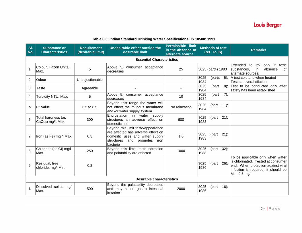
6-4 | P a g e
Table 6.3: Indian Standard Drinking Water Specifications: IS 10500: 1991
Sl. No.
Substance or Characteristics
Requirement (desirable limit)
Undesirable effect outside the desirable limit
Permissible limit in the absence of alternate source
Methods of test (ref. To IS)
Remarks
Essential Characteristics
1. Colour, Hazen Units, Max.
5 Above 5, consumer acceptance decreases
25 3025 (part4) 1983 Extended to 25 only if toxic substances, in absence of alternate sources.
2. Odour Unobjectionable - - 3025 (parts 5): 1984
A test cold and when heated Test at several dilution
3. Taste Agreeable - - 3025 (part 8): 1984
Test to be conducted only after safety has been established
4. Turbidity NTU, Max. 5 Above 5, consumer acceptance decreases
10 3025 (part 7): 1984
5 PH value 6.5 to 8.5 Beyond this range the water will not effect the mucous membrane and /or water supply system
No relaxation 3025 (part 11): 1984
6. Total hardness (as CaCo3) mg/l, Max.
300 Encrustation in water supply structures an adverse effect on domestic use
600 3025 (part 21): 1983
7. Iron (as Fe) mg /l Max. 0.3
Beyond this limit taste/appearance are affected has adverse effect on domestic uses and water supply structures and promotes iron bacteria
1.0 3025 (part 21): 1983
8. Chlorides (as CI) mg/l Max.
250 Beyond this limit, taste corrosion and palatability are affected
1000 3025 (part 32): 1988
9. Residual, free chloride, mg/l Min.
0.2 3025 (part 26): 1986
To be applicable only when water is chlorinated. Tested at consumer end. When protection against viral infection is required, it should be Min. 0.5 mg/l
Desirable characteristics
l. Dissolved solids mg/l Max.
500 Beyond the palatability decreases and may cause gastro intestinal irritation
2000 3025 (part 16): 1986

6-5 | P a g e
Sl. No.
Substance or Characteristics
Requirement (desirable limit)
Undesirable effect outside the desirable limit
Permissible limit in the absence of alternate source
Methods of test (ref. To IS)
Remarks
2. Calcium (as Ca) mg/l Max.
75 Encrustation in water supply structure and adverse effects on domestic use
200 3025 (Part 16) 1986
3. Magnesium (as Mg) mg/l, Max.
30 Encrustation in water supply structure and adverse effects on domestic use
1.5 16,33,34 of IS 3025: l964
4. Copper (as Cu) mg/l Max.
0.05 Beyond taste, discoloration of pipes, fitting and utensils will be caused beyond this
0.3 35 of 3025: 1964
5. Manganese (as Mn) mg/l, Max.
Beyond this limit taste/appearance are affected, has adverse effect on domestic uses and water supply structures.
0.3 35 of 3025: 1964
6. Sulphate (as 200 So2), mg/l, Max.
200 Beyond this causes gastro intestinal irritation when magnesium or sodium are present
400 3025(part 24):l986 May b extended up to 400 provided ( as Mg) does not exceed 30
7. Nitrate (as No2) mg/l, Max.
45 Beyond this methamoglobunemia take place
100 3025 (part24): 1988
To be tested when pollution is suspected
8 Fluoride (as F) mg/l, Max.
1.0 Fluoride may be kept as low as possible. High fluoride may cause fluorosis
1.5 23of 3025:1964 To be tested when pollution is suspected
9 Phenolic compounds (as C6H5OH) mg/l, Max.
0.001 Beyond this it may cause objectionable taste and odour
0.002 54of 3025:1964 To be tested when pollution is suspected
10 Mercury (as Hg) mg/l, Max.
0.001 Beyond this the water becomes toxic
No relaxation (See not mercury ion analyzes)
To be tested when pollution is suspected
11 Cadmium (as cd), mg/l, Max.
0.01 Beyond this the water becomes toxic
No relaxation (See note) To be tested when pollution is suspected
12 Selenium, (as Se). mg/l, Max.
0.01 Beyond this the water becomes toxic
No relaxation 28of 3025:1964 To be tested when pollution is suspected
13 Arsenic (As) mg/l, Max.
0.05 Beyond this the water becomes toxic
No relaxation 3025 (part 37); 1988
To be tested when pollution is suspected
14 Cyanide (as CN) mg/l, Max.
0.05 Beyond this the water becomes toxic
No relaxation 3025 (part 27) 1988
To be tested when pollution is suspected
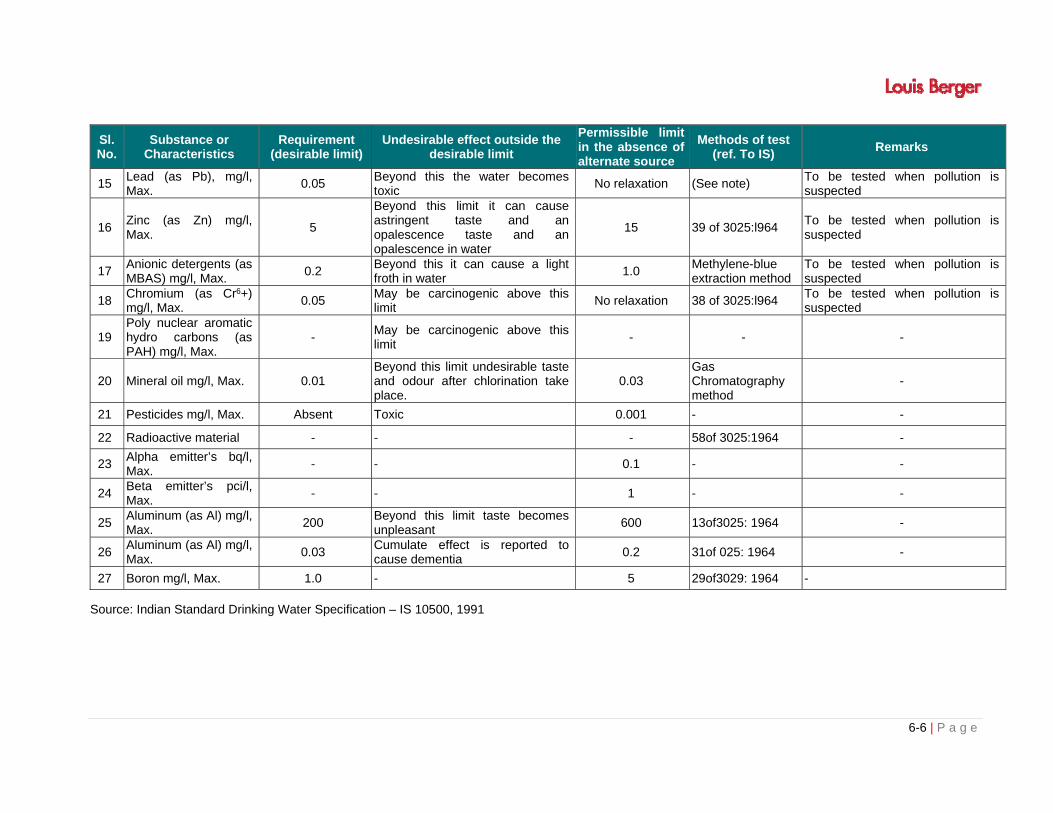
6-6 | P a g e
Sl. No.
Substance or Characteristics
Requirement (desirable limit)
Undesirable effect outside the desirable limit
Permissible limit in the absence of alternate source
Methods of test (ref. To IS)
Remarks
15 Lead (as Pb), mg/l, Max.
0.05 Beyond this the water becomes toxic
No relaxation (See note) To be tested when pollution is suspected
16 Zinc (as Zn) mg/l, Max.
5
Beyond this limit it can cause astringent taste and an opalescence taste and an opalescence in water
15 39 of 3025:l964 To be tested when pollution is suspected
17 Anionic detergents (as MBAS) mg/l, Max.
0.2 Beyond this it can cause a light froth in water
1.0 Methylene-blue extraction method
To be tested when pollution is suspected
18 Chromium (as Cr6+) mg/l, Max.
0.05 May be carcinogenic above this limit
No relaxation 38 of 3025:l964 To be tested when pollution is suspected
19 Poly nuclear aromatic hydro carbons (as PAH) mg/l, Max.
- May be carcinogenic above this limit
- - -
20 Mineral oil mg/l, Max. 0.01 Beyond this limit undesirable taste and odour after chlorination take place.
0.03 Gas Chromatography method
-
21 Pesticides mg/l, Max. Absent Toxic 0.001 - -
22 Radioactive material - - - 58of 3025:1964 -
23 Alpha emitter’s bq/l, Max.
- - 0.1 - -
24 Beta emitter’s pci/l, Max.
- - 1 - -
25 Aluminum (as Al) mg/l, Max.
200 Beyond this limit taste becomes unpleasant
600 13of3025: 1964 -
26 Aluminum (as Al) mg/l, Max.
0.03 Cumulate effect is reported to cause dementia
0.2 31of 025: 1964 -
27 Boron mg/l, Max. 1.0 - 5 29of3029: 1964 -
Source: Indian Standard Drinking Water Specification – IS 10500, 1991

6-7 | P a g e
6.3 NOISE QUALITY MONITORING
As with air and water quality, the noise levels shall be monitored at already designated locations
in accordance with the Ambient Noise Quality standards given in Table 6.4 below. The location,
duration and the noise pollution parameters to be monitored and the responsible institutional
arrangements are detailed in the Environmental Monitoring Plan Table 6.5
Table 6.4: National Ambient Noise Quality Standards
Sl. No. Area Code Category of Zone Limit Leq in dB (A)
*Day **Night
1 A Industrial 75 70
2 B Commercial 65 55
3 C Residential 55 45
4 D Silence Zone 50 40
* Day Time – 6.00 am – 9.00 pm (l5 hours)
** Night Time – 9.00 pm – 6.00 am (9 hours)
6.4 ENVIRONMENTAL MONITORING PLAN
Monitoring plan for various performance indicators for construction and monitoring stages is
summarized in Table 6.5.

6-8 | P a g e
Table 6.5: Environmental Monitoring Plan
Env. Component
Project Stage
Monitoring Institutional Responsibility
Parameters Special
Guidance Standards Location Frequency Duration
Implementation
Supervision
Air
Construction Stage
PM10,PM2.5, SO2, NOX, CO, HC
Respirable Dust sampler to be located 50 m from the hot mix plant in the downwind direction. Use method specified by CPCB for analysis
Air (P&CP) Act,1981 and its amendment
Hot mix Plant / Batching Plant
Seven locations Quarterly for three years
Continuous 24 hours or for 1 full working day.
Contractor through
approved monitoring
agency
P I U, MMRDA
Construction Stage
PM10,PM2.5
Respirable Dust Sampler to be located 40 m from the earthworks site downwind direction. Use method specified by CPCB for analysis
Air (P&CP) Act, 1981 and its amendment.
Stretch of the MMC where construction is in progress at the site
Seven locations, thrice in a year for three years
Continuous 24 hours or for 1 full working day
Contractor through
approved monitoring
agency
P I U, MMRDA
Operational Stage
PM10,PM2.5, SO2, NOX, CO, HC
Respirable Dust Sampler to be located 50m from the plant in the downwind direction. Use method specified by CPCB for analysis
Air(P&CP) Act,1981 and its amendment
At locations as listed in Chapter 3 (Table 3.5) Air quality locations or as specified by the EO-IC/ P I U/ MMRDA
Three times in a year for one year at Seven locations
Continuous 24 hours or for 1 full working day
P I U, MMRDA
P I U, MMRDA
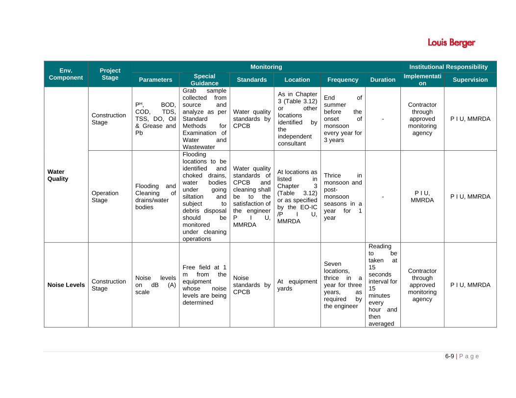
6-9 | P a g e
Env. Component
Project Stage
Monitoring Institutional Responsibility
Parameters Special
Guidance Standards Location Frequency Duration
Implementation
Supervision
Water Quality
Construction Stage
PH, BOD, COD, TDS, TSS, DO, Oil & Grease and Pb
Grab sample collected from source and analyze as per Standard Methods for Examination of Water and Wastewater
Water quality standards by CPCB
As in Chapter 3 (Table 3.12) or other locations identified by the independent consultant
End of summer before the onset of monsoon every year for 3 years
-
Contractor through
approved monitoring
agency
P I U, MMRDA
Operation Stage
Flooding and Cleaning of drains/water bodies
Flooding locations to be identified and choked drains, water bodies under going siltation and subject to debris disposal should be monitored under cleaning operations
Water quality standards of CPCB and cleaning shall be to the satisfaction of the engineer P I U, MMRDA
At locations as listed in Chapter 3 (Table 3.12) or as specified by the EO-IC /P I U, MMRDA
Thrice in monsoon and post-monsoon seasons in a year for 1 year
- P I U,
MMRDA P I U, MMRDA
Noise Levels Construction Stage
Noise levels on dB (A) scale
Free field at 1 m from the equipment whose noise levels are being determined
Noise standards by CPCB
At equipment yards
Seven locations, thrice in a year for three years, as required by the engineer
Reading to be taken at 15 seconds interval for 15 minutes every hour and then averaged
Contractor through
approved monitoring
agency
P I U, MMRDA

6-10 | P a g e
Env. Component
Project Stage
Monitoring Institutional Responsibility
Parameters Special
Guidance Standards Location Frequency Duration
Implementation
Supervision
Operation Stage
Noise levels on dB (A) scale
Equivalent Noise levels using an integrated noise level meter kept at a distance of 15 m from edge of Pavement
Noise standards by CPCB
As directed by the Engineer (At maximum 4 locations)
Seven locations, thrice a year for 1 years during the construction period
Readings to be taken at 15 seconds interval for 15 minutes every hour and then averaged.
P I U, MMRDA
P I U, MMRDA
Soil Erosion
Construction Stage
Turbidity in Storm Water Silt load in ponds, water courses
----
As specified by the engineer P I U, MMRDA), Water quality standards
As specified by the engineer P I U, MMRDA Independent Consultant, all along the project corridor
Seven locations ,Pre-monsoon and post-monsoon seasons for 3 years
---- Contractor P I U, MMRDA
Operational Stage
Turbidity in Storm Water Silt load in ponds, water courses
----
As specified by the engineer P I U, MMRDA / Water quality standards
As specified by the engineer P I U, MMRDA / Independent consultant, all along the project corridor
Seven locations Three times a year for one year
---- P I U,
MMRDA P I U, MMRDA
Plantation of trees
Construction as well as Operational Stage
75% Plant Survival
The success of tree planting. Rate of survival after six months, one
-
All along the project corridor(in acquired land)
Maintenance for three to five years after plantation
-
NGO, and P I U,
MMRDA P I U, MMRDA
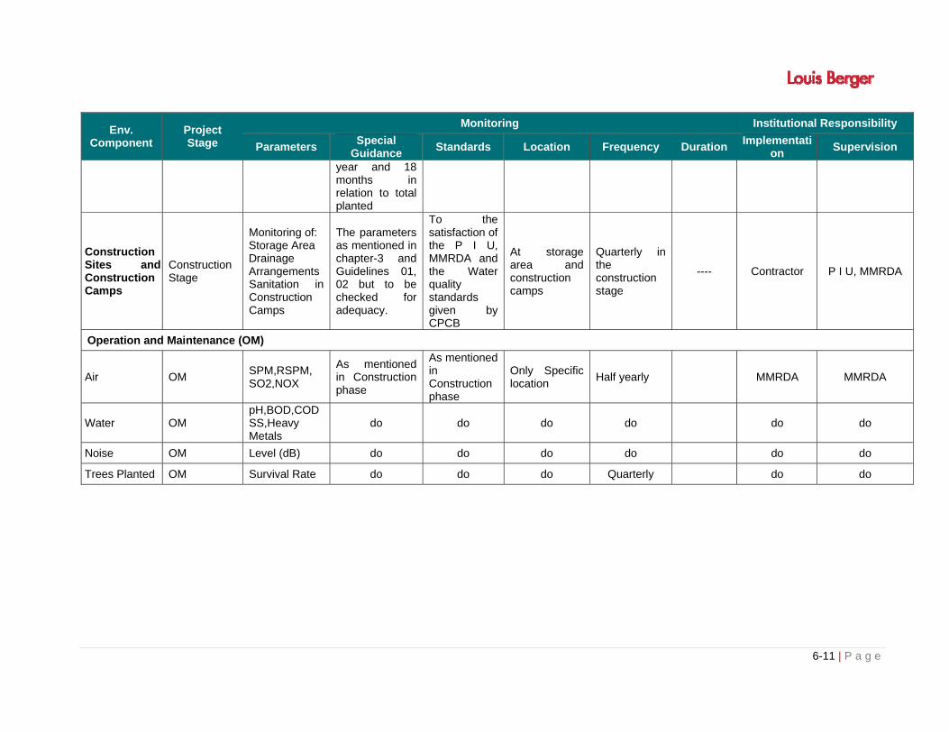
6-11 | P a g e
Env. Component
Project Stage
Monitoring Institutional Responsibility
Parameters Special
Guidance Standards Location Frequency Duration
Implementation
Supervision
year and 18 months in relation to total planted
Construction Sites and Construction Camps
Construction Stage
Monitoring of: Storage Area Drainage Arrangements Sanitation in Construction Camps
The parameters as mentioned in chapter-3 and Guidelines 01, 02 but to be checked for adequacy.
To the satisfaction of the P I U, MMRDA and the Water quality standards given by CPCB
At storage area and construction camps
Quarterly in the construction stage
---- Contractor P I U, MMRDA
Operation and Maintenance (OM)
Air OM SPM,RSPM, SO2,NOX
As mentioned in Construction phase
As mentioned in Construction phase
Only Specific location
Half yearly MMRDA MMRDA
Water OM pH,BOD,COD SS,Heavy Metals
do do do do do do
Noise OM Level (dB) do do do do do do
Trees Planted OM Survival Rate do do do Quarterly do do

7-i | P a g e
TABLE OF CONTENTS
CHAPTER- 7: ADDITIONAL STUDIES ................................................................................................. 7-1
7.1 PUBLIC CONSULTATION ......................................................................................................... 7-1
7.1.1 Identification of Stakeholders ........................................................................................ 7-2
7.1.2 Planning For Consultation ............................................................................................. 7-2
7.1.3 Consultation during Feasibility Stage ............................................................................ 7-3
7.1.4 Structured Consultation with Stakeholders ................................................................... 7-5
7.1.5 Consultation Mechanism: Developing Sense of Ownership .......................................... 7-5
7.1.6 Role and Responsibilities Identified During Consultation .............................................. 7-5
7.1.7 Strategies for Continued Consultation........................................................................... 7-6
7.1.8 Lessons Learnt from Consultation and Suggested Framework for Social Management 7-7
7.2 RISK ASSESSMENT ................................................................................................................. 7-8
7.3 DISASTER MANAGEMENT PLAN ............................................................................................ 7-8
7.3.1 Types of Disaster Causing Interruption to Metro Train Services ................................... 7-9
7.3.2 Classification of mergencies ......................................................................................... 7-9
7.3.3 Potential Mergencies .................................................................................................. 7-10
7.3.4 Categorization of Emergency ...................................................................................... 7-10
7.3.5 Scenarios .................................................................................................................... 7-11
7.3.6 Response Organization .............................................................................................. 7-12
7.3.7 District Disaster Management Authority ...................................................................... 7-15
LIST OF TABLES
Table 7.1: Planning and Present Status of Consultation .................................................................... 7-2
Table 7.2: Role and Responsibilities Identified after Consultation ..................................................... 7-5


7-1 | P a g e
CHAPTER- 7: ADDITIONAL STUDIES
7.1 PUBLIC CONSULTATION
Stake holder consultation and participation is an integral part of the environmental and social
impact assessment and management process. The stake holders of a project include;
Affected persons/communities (on either side of the project corridor),
Institutional stakeholders such as PCB, local bodies, water resources department,
environmental department, Industrial (mining & geology) department, Forest, district
administration and wildlife department etc.
Non-governmental institutions like NGOs.
Conducting consultations at micro-level (e.g. project level along the corridor) and macro-level
(e.g. District/State level institutional consultations) is to help the planners to integrate the short
term and long term requirements of the Local, State, Regional and National goals in to the
planning process. The State, National and Regional goals are generally set by the legislations
and policies in the various human actions by controlling or limiting the activities in order to reduce
and nullify the adverse impact generated by infrastructure projects like multi transportation
system. The quality of MMC design does not limit itself in to just the engineering requirements of
the product but should integrate the quality assurance in the process, product and services as
well. In that process the benefits accrued due to the project implementation multiply many fold
and the general appreciation from all sections of the society would be largely vibrant positive.
The various players directly or indirectly involved in the process, product and services are design
and supervision consultants (engineers and other professionals) contractors (who actually build
the Highway and Railways).
The proposed Multi Model Corridor (MM) from Navghar to Chirner, requires active participation of
the people in issues related to land acquisition preferably through negotiation, and adverse
impact of construction of MMC on high embankment in terms of accessibility, bifurcation of
village land and parcel of land of a farmer. More often suggestion, opinion given by the people
improves technical and economic efficiency of the project, suggested improvements proposal of
the people also generates sense of ownership within communities thus eases implementation as
well as operation and management.
During the project preparation stage, the consultant has conducted consultation focusing on
impact of loss of fertile agricultural land and suitable methodology to arrive out realistic market
prices, compensation for other assets which are otherwise not under the purview of LA Act,
alternative source of livelihood of the people, impact of loss of accessibility and way to find out
solution etc. The consultant has also attempted to develop strategies for continued consultation
during construction and post construction stages. The sustained communication strategies during
project cycle will suggest corrective measures to project output. Following sections also illustrate
efforts undertaken by the project preparation team to involve stakeholders in project planning
such as identification of stakeholders, planning for consultation at different stages, future

communication strategies for sustainable community capacity building and ensuring people
about their involvement during project cycle.
7.1.1 Identification of Stakeholders
While conducting regular meeting with Mumbai Metropolitan Development Authority (MMRDA),
Engineers (Government of Maharashtra), Divisional Forest Officials, Wildlife Warden and
Revenue Officials for proposed MMC. The consultant has identified following important
Stakeholders for this project while doing field level studies.
Primary Stakeholders (Main stakeholders)
Potential PAPs, Forest Department, Wildlife department, and Revenue department
Secondary Stakeholders (Other stakeholders)
MMRDA engineers Forest Officials Wildlife Warden Pollution Control Board Field level MMRDA Engineers, Groups of affected persons; Village representatives like Sarpanch and members, Village level health workers, Patwaris Local voluntary organizations like NGOs; State AIDS Control Society representatives Other project stakeholders such as official of line Department
7.1.2 Planning For Consultation
The consultation mechanism has been planned in stages at each level of project preparation.
While village level and Tehsil level consultation is already initiated and other consultation is
planned during course of preparation Resettlement Plan. One of the features of present
consultation programme is have continued involvement of MMRDA and concern stake holders.
The consultation strategies and Planning have been discussed below.
Table 7.1: Planning and Present Status of Consultation
Stakeholders Level of
Consultation Start
Stages Future course
PAPs, community, Women groups, NGOs and
other vulnerable groups like ST & SC
Village level EIA
preparation Started, Contd…
MMRDA Officials at the Field At Bridge and Road
Division EIA
preparation First round completed
Forest Official, Wild life and CRZ officials
Range officers, DFO, In charge Wild Life warden and CCF, State CRZ athority
EIA preparation
Forest & Wild life land
diversion and joint inspection
in progress District Officials of line
Department, such as Revenue Authority, Forest, CRZ & Wild
life, Land Acquisition
District level EIA
preparation In progress
PSACS and its PSU, Social welfare Board,
State level EIA
preparation In progress
The above mentioned planning of consultation have been done after having understood the
mechanism of execution of project especially LA, Forest, CRZ and Wild life clearance issues,
7-3 | P a g e
methodologies to be adopted for matter related compensation etc. The planning will envisage
future course of stakeholder’s involvement.
7.1.2.1 Type of Consultations
Various type of consultations carried out during the investigations include;
One to one meetings with affected communities
Focus group meetings with a group or section of communities
Consultation with stakeholder institutions
At project level (e.g. DFO, Forest Range Officer, Wildlife Warden and Panchayat
pradhans and members)
At State level (PCB)
CRZ Authority
One to one meetings are generally held with a few members of local communities. These
consultations sometimes focus on one or more specific issues for example saving of trees along
the proposed corridor. Wherever possible such types of consultations were generally held with
informed people. Informed people are those members of the local communities who in their past
had a thorough experience and has geographic, political and general knowledge about the
country and requirements of the communities.
Focus group meetings are usually conducted with a sample section of the community generally
with a good representation from the affected communities. Such meetings usually provided
substantial information about the community concerns.
Further, stake holder institutions were consulted at project level (e.g. DFOs, Forest Range Officer
etc), wildlife officer and also at State level (PCB & CRZ etc).
Formal and informal Local consultations
A number of formal and informal consultations have been carried out as a part of the project
preparation. During the formal consultations which are very important; minutes of meetings
(MOM) were also prepared. Since meetings with DFOs & wild life wardens are crucial to
implement the forest regulations, all meetings with DFOs & Wild life warden have been noted.
The informal consultations are usually held informally with officials to understand the institutional
concerns at a given specific location for example issue related to a section of the project road.
7.1.3 Consultation during Feasibility Stage
At the feasibility stage of the project preparation, consultation at individual level, in groups and
focused group discussions in the villages, were held. The consultation mechanism devised to
ensure that people are consulted; their project related opinion are gathered, opinion and
preferences about project related engineering inputs are shared with the community and
outcome of consultation has been recorded. Following steps have been initiated to have better
communication of the project.

7.1.3.1 Information Dissemination
While doing social assessment survey the consultant has conducted information dissemination
along the project route in following manner.
Potential project affected families of the affected were inform about the proposed widening of
the highway.
Pictorial Methods and to explain about improvement proposals like location of underpasses,
cart crossing for the affected villages,
Information dissemination through pamphlet among the villagers explaining feature of
proposed widening (4-laning) of highway.
People are requested to gather at common places such as places of panchayat, Gramsabha and
resource person of project preparation team explaining about the project using board and
markers.
INFORMATION DISSEMINATION ABOUT PROPOSED MULTI MODEL CORRIDOR (NAVGHAR
TO CHIRNER) (leaflet) MUMBAI METROPOLITAN DEVELOPMENT AUTHORITY
MMRDA, Government of Maharashtra through has planned to Multi Model Corridor from Navghar to Chirner, by providing better quality and safer roads/metro rail to the users in sustainable manner. Some of the basic features of Mumbai Multi Model Corridor project are: This project will have good quality of 8-lane express with 4 lane service road with Metro Rail
facility in median. Provision of underpasses and overpasses at important location for safe movement Land acquisition mainly through mutual negotiation. Resettlement and Rehabilitation will be done as per National Policy on rehabilitation and
resettlement. Felling of trees and diversion of forest land Traffic safety will be on priority in present road planning. HIV/AIDS awareness will be part of social planning under the project.
The people should suggest about the project Improved MMC planning Role of Elected member (PRIs) in planning and Implementation especially in consent award Areas of conflict of the project Location of underpasses and overpasses Major junction where accidents occur frequently and require grade separators and service roads Management of drainage
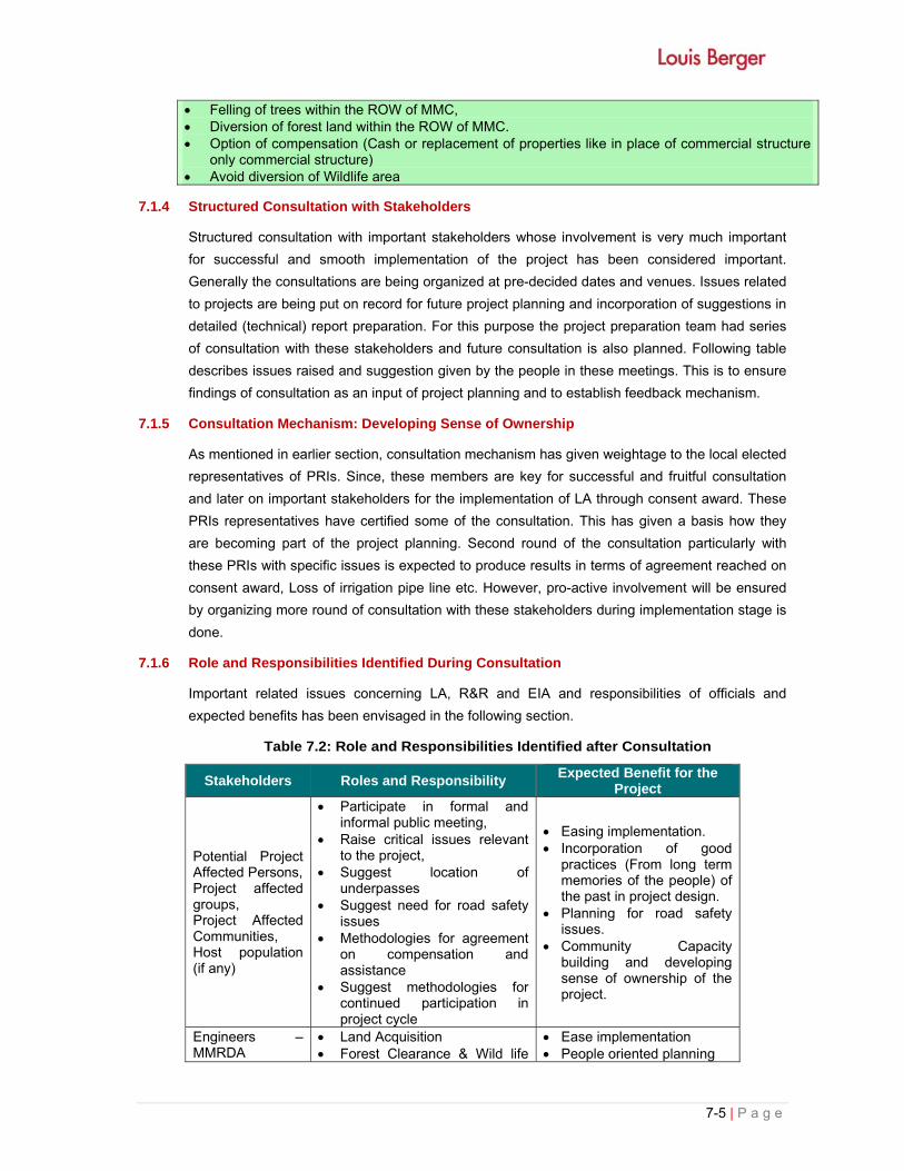
7-5 | P a g e
Felling of trees within the ROW of MMC, Diversion of forest land within the ROW of MMC. Option of compensation (Cash or replacement of properties like in place of commercial structure
only commercial structure) Avoid diversion of Wildlife area
7.1.4 Structured Consultation with Stakeholders
Structured consultation with important stakeholders whose involvement is very much important
for successful and smooth implementation of the project has been considered important.
Generally the consultations are being organized at pre-decided dates and venues. Issues related
to projects are being put on record for future project planning and incorporation of suggestions in
detailed (technical) report preparation. For this purpose the project preparation team had series
of consultation with these stakeholders and future consultation is also planned. Following table
describes issues raised and suggestion given by the people in these meetings. This is to ensure
findings of consultation as an input of project planning and to establish feedback mechanism.
7.1.5 Consultation Mechanism: Developing Sense of Ownership
As mentioned in earlier section, consultation mechanism has given weightage to the local elected
representatives of PRIs. Since, these members are key for successful and fruitful consultation
and later on important stakeholders for the implementation of LA through consent award. These
PRIs representatives have certified some of the consultation. This has given a basis how they
are becoming part of the project planning. Second round of the consultation particularly with
these PRIs with specific issues is expected to produce results in terms of agreement reached on
consent award, Loss of irrigation pipe line etc. However, pro-active involvement will be ensured
by organizing more round of consultation with these stakeholders during implementation stage is
done.
7.1.6 Role and Responsibilities Identified During Consultation
Important related issues concerning LA, R&R and EIA and responsibilities of officials and
expected benefits has been envisaged in the following section.
Table 7.2: Role and Responsibilities Identified after Consultation
Stakeholders Roles and Responsibility Expected Benefit for the
Project
Potential Project Affected Persons, Project affected groups, Project Affected Communities, Host population (if any)
Participate in formal and informal public meeting,
Raise critical issues relevant to the project,
Suggest location of underpasses
Suggest need for road safety issues
Methodologies for agreement on compensation and assistance
Suggest methodologies for continued participation in project cycle
Easing implementation. Incorporation of good
practices (From long term memories of the people) of the past in project design.
Planning for road safety issues.
Community Capacity building and developing sense of ownership of the project.
Engineers –MMRDA
Land Acquisition Forest Clearance & Wild life
Ease implementation People oriented planning

Stakeholders Roles and Responsibility Expected Benefit for the
Project Clearance
Participate in Public meetings Participate in Tahsil and
District Level Meeting
Ensured public cooperation Determination of market
value
Forest Official/PCB/wildlife/ CRZ
Enumeration of trees within the Row of MMC
Identification of eco sensitive hot spots(if any)
Scrutiny of application form for forest clearance
Permission for tree cutting Salvaging/Auctioning of trees Land Diversion and NOC from
wild life NOC under air and water
prevention Act CRZ mapping & clearance
Faster Forest and wildlife Clearance for the project
Transfer of Forest Land will become easier
Achievement of Sustainable development goal
Land Acquisition Officials
Authentication of existing 4(1) notification
Ensure availability of land for construction of MMC
Timely evacuation of Corridor
Speedy and timely land acquisition
Line Department Officials (Irrigation, Telephone, Municipalities, Panchayat)
Permission to acquire land from irrigation department, PHED,
Estimates for Utilities Dovetailing Government
schemes
Eases implementation
NGOs/CBOs Self Help Group, Water User Association PRIs. ORWs
Ensure public participation in project preparation and implementation,
Assist MMRDA and Government for dovetailing Government schemes for income generation schemes
Public are informed Opinion and preferences
are known Easy to develop
community capacity development plan.
7.1.7 Strategies for Continued Consultation
The consultation will be continued as the project enters in the implementation stage. Several
additional rounds of consultations with PAPs will be done through NGOs involvement during
Resettlement Plan implementation. These consultations during implementation will involve
agreements on compensation and assistance options and entitlement package preferably under
consent award. The other round of consultation will take place when possession of acquired land
is transferred from the PAFs to the requiring body.
The following set of activities will be pursued for effective implementation of Social/
Environmental Management Plan.
1. For the benefit of the community in general and PAPs in particular, Resettlement Plan will be
translated in Marathi and will be made available at local public offices for easy access for
information.
2. Key features of the entitlements under consent award as well as under the provision of LA
Act will be displayed in billboards of the affected villages.
7-7 | P a g e
3. Together with the Land Acquisition Expert, the PIU will conduct information dissemination
sessions and solicit the help of the local community/religious leaders and encourage the
participation of the PAPs in the implementation.
4. Focus attention will be made for people who lose their entire land or become small farmer or
marginal farmer; this will be ensured that their needs are specifically taken into
consideration.
5. The Land Acquisition Expert involved in the implementation Resettlement Plan will organize
public meetings, and will appraise the communities about the progress in the implementation
of project works.
6. The Land Acquisition Expert will organize public meetings to inform the community about the
payment and assistance paid to the community under the project. Regular update of the
resettlement program will be placed for public display at MMRDA offices.
7. Participation of PAPs will also be ensured through their involvements in various local
committees such as, committees for consent award, District committees, and Grievance
Redress Committee etc.
7.1.8 Lessons Learnt from Consultation and Suggested Framework for Social Management
7.1.8.1 Issues of Compensation
Following the Right to Fare Compensation and Transparency in Land Acquisition, Rehabilitation
and Resettlement Act 2013, PAPs will receive compensation at replacement value. In order to
help PAFs in their economic rehabilitation process consent award should be preferred. MMRDA
should devise a mechanism in such a manner that compensation at true market value is given to
the land owner as compensation and rehabilitation package for the loss of accessibility under
social exaction cost as per the persisting law.
7.1.8.2 Implementation Framework
Implementation of RAP entirely will be done by the MMRDA with the help of Administrator or the
nominated competent authority. However, MMRDA will have very limited capacity of handling
issue of LA and R&R. Therefore, it is suggested that RAP should be implemented with the help
of facilitating NGOs.
7.1.8.3 Community Properties Resources (CPRs) Enhancement
Regarding community properties enhancement, village community is willing to come forward to
cooperate with MMRDA in the enhancement of religious properties. This is learnt from
consultation that generally CPRs do not receive due attention during construction as a result
actual enhancement do not take place. Therefore, project authority should plan for alternative
implementation arrangement or strengthen its periodic monitoring of physical and financial
progress of such enhancement.
7.1.8.4 Issues of Tree Cutting
Proposed MMC alignment will traverses through agricultural land, low land areas, mangroves,
forests & wild life national park and eco sensitive zone. The embankment height at most of

stretches will be raised so that accident could be avoided or minimized. People have suggested
to plant local species of tree along the stretches so that damage to environment could be
minimized. Even people have suggested to plant herbs and canopy building trees at the along
the corridor.
7.1.8.5 Compensatory Afforestation
As per the provision of Forest Dept., Government of Maharashtra, compensatory afforestation
will be done on land equal to thrice of affected Forest and Mangroves area. Community during
consultation has suggested that the compensatory afforestation should be carried out in
consultation with the community and selection of tree should provide shelter to the people
(Canopy building trees) and fruit bearing trees.
7.1.8.6 Monitoring Plan and Training
Information collected during environment (air quality, water quality and other parameters) survey
and consultation with key stakeholders suggests periodic monitoring plan should be gauged by
considering specific but limited number of environmental parameters. Therefore, Monitoring
strategies for the project should devise a specific plan. Training and capacity building component
of environmental team should be part of consolidated training program of MMRDA and budgeted
in training and institutional component of the project.
7.2 RISK ASSESSMENT
The objectives of carrying out Risk Assessment Study for any project is to study the risk involving
hazardous chemicals and their consequences. Present project does not create any hazardous
chemicals which will create risk to the human as well as environmental health. All efforts will be
made to preserve trees including evaluation of minor design adjustments/ alternatives to save
trees. Specific attention will be given for protecting giant trees, and locally important trees
(religiously important etc.).
Tree cutting is to proceed only after all the legal requirements including attaining of In-principle
and Formal Tree felling and forest land diversion permission from Forest Dept. under Forest
Conservation Act, 1980. A clearance from the Forest Dept. and subsequently a written order is
issued to the Contractor.
All environmental impact associated with the project which will be either avoid or minimized
during planning stage if it is not possible then it will be compensated suitably, so that project will
become eco-friendly.
7.3 DISASTER MANAGEMENT PLAN
India is prone to a large number of natural as well as man-made disasters. Disasters disrupt
progress and destroy the hard-earned fruits of painstaking developmental efforts in quest for
progress. Considering the consequences of past disasters priority has been given to preventive,
mitigation and preparedness measures. Preparation of Disaster Management Plan (DMP) is a
part of it.
Disasters can be due to human error or to rough weather conditions, they can cause serious
injuries, loss of lives, and extensive damages to property and equipment. Most of the time

7-9 | P a g e
disasters arise with no warning and sometimes they may not be controlled. The first few minutes
determines the effectiveness of the emergency plan. Dealing with an emergency situation may
require external aid. The quickest and well prepared the response is, the less likely there will be
serious damages. Emergency planning enables to reduce the thinking time and thus permit to
decrease the potentiality of damages. Emergency plans and equipment may never be used but
they are essential. The key objectives of the disaster management plan are:
Provide the framework for an integrated multi-agency crisis response to a significant disaster
incident within the MMC
Clarify specific roles and responsibilities
Safest possible environment during the resolution of the incident
Reduce the adverse impacts of an emergency incident on personal, business and the
general community
Provide a management framework for the sub plans and associated specific response plan
Provide continued education review and testing.
7.3.1 Types of Disaster Causing Interruption to Metro Train Services
Human/Equipment failure:
The following disasters/ accidents may be caused by human/equipment failure, which may affect
normal movement of train and road transport services with loss of life or property or both.
Collision and Road Accident
Derailment
Fire in vehicle and Train/ at Station/ with in ROW
Natural Calamities:
• Landslide
• Earth quake
• Flood
Sabotage:
• Terrorist Attack
• Setting fire to train/railway installations and railway property
• Bomb blasts
• Placing of obstructions on track to cause disruption to traffic
• Tampering with railway fittings to cause accidents
• Release of Chemical or Biological Gas in trains, stations, tunnel
7.3.2 Classification of mergencies
In an emergency situation defining the level of risk is the initial step. Classifying emergencies
enable to understand quickly what is likely to happen and to what extent the emergency plans
will be driven. The nature of the emergency refers as if it is a man-made disaster or a natural
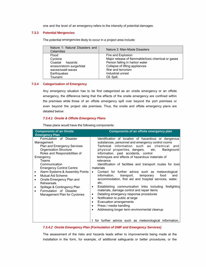
one and the level of an emergency refers to the intensity of potential damages.
7.3.3 Potential Mergencies
The potential emergencies likely to occur in a project area include:
� Nature 1: Natural Disasters and Calamities � Nature 2: Man-Made Disasters
� Flood � Cyclone � Coastal hazards:
erosion/storm surge/tidal waves/swell waves
� Earthquakes � Tsunami
� Fire and Explosion � Major release of flammable/toxic chemical or gases � Person falling in harbor water � Collapse of lifting appliances � War and terrorism � Industrial unrest � Oil Spill,
7.3.4 Categorization of Emergency
Any emergency situation has to be first categorized as an onsite emergency or an offsite
emergency, the difference being that the effects of the onsite emergency are confined within
the premises while those of an offsite emergency spill over beyond the port premises or
even beyond the project site premises. Thus, the onsite and offsite emergency plans are
detailed below:
7.3.4.1 Onsite & Offsite Emergency Plans
These plans would have the following components:
Components of an Onsite Emergency Plan
Components of an offsite emergency plan
� Formulation of Disaster Management
Plan and Emergency Services � Organization Structure � Roles and Responsibilities of Emergency
Teams � Communication � Emergency Control Centre Alarm Systems & Assembly Points Mutual Aid Scheme Onsite Emergency Plan and
Rehearsals Spillage & Contingency Plan Formulation of Disaster
Management Plan for Cyclones
� Identification of location of hazardous or dangerous substances, personnel and emergency control rooms
� Technical information such as chemical andphysical properties, dangers, etc. Background information, past accidents, control techniques and effects of hazardous materials of relevance
� Identification of facilities and transport routes for toxicmaterials Contact for further advice such as meteorological
information, transport, temporary food and accommodation, first aid and hospital services, water, etc.
Establishing communication links including firefightingmaterials, damage control and repair items
Detailing emergency response procedures Notification to public at large Evacuation arrangements Press / media handling Addressing longer term environmental cleanup t for further advice such as meteorological information,
7.3.4.2 Onsite Emergency Plan (Formulation of DMP and Emergency Services)
The assessment of the risks and hazards leads either to improvements being made at the
installation in the form, for example, of additional safeguards or better procedures, or the
7-11 | P a g e
decision being taken that the risk is sufficiently small to be accepted. The DMP must be
related to the final assessment and it is the responsibility of the MMC management to
formulate it. The plan will include the following elements.
Assessment of the magnitude and nature of the events foreseen and the probability of
their occurrence
o Formulation of the plan and liaison with outside authorities, including the emergency services
o Procedures for raising the alarm and communication both within and outside the port
o Appointment of key personnel and their duties and responsibilities (organizational structure)
o Emergency Control Centre
o Action on site and Action off site
7.3.5 Scenarios
Coastal flooding: Coastal flooding occurs when high tides, combine with low barometric
pressure and high winds. During the south west monsoon heavy rainfall and flood are more
likely to occur.
Cyclonic storms: Storms vary in size and intensity, in severe situation port operations
should be interrupted. High winds are particularly hazardous.
Earthquake: Project area falls under earthquake zone III which corresponds to a magnitude of
6.5 or more on the Richter scale. That means that the risk of earthquake and its
consequences are non- negligible. Buildings and facilities construction must be designed to
minimize the consequences of an earthquake.
Tsunami: The phenomenon Tsunami is a series of travelling ocean waves of extremely long
length generated primarily by Submarine earthquakes. Tsunami has already occurred in the
southern coast (Tamilnadu and Kerala) and thus may likely to occur again. Nevertheless,
Tsunamis are unexpected and unpredictable but are a rare natural phenomenon. Mumbai lies
on the western coast of India by the bank of Arabian Sea. Mumbai is made from the group
of seven islands and is thus referred to as the Island city. MMC may also get impacted by
the Tsunami.
Fire and explosion: A fire incident is described as the destruction or partial destruction by
fire of a building or its contents. In metro there are a lot of sources of fire ignition because of
the presence of wooden facilities and inflammable substances. A fire spread can be very
fast, to confine the fire to manageable limits the reaction must be very quick. Fire can also
accrue due to road accident and sparking in running vehicle may also cause serious
causalities.
Collapse of lifting appliances, buildings, sheds: Road and Metro construction include
the intervention of a lot of lifting and heavy appliances, which can collapse under man-made
error or rough weather condition. The managers are trained to respond to this problem. They
should monitor all safety measures necessary and coordinate response with other authorities
if necessary.

Transportation Accidents: Transportation mishaps could endanger human lives, lead to
chemical spills, fires, explosions and other problems. These emergencies may call for special
operations such as evacuation and rescue. Usually transportation incidents affect only
relatively small areas and involve only a small number of people.
Terrorist attack and Bomb threat: Due to political climate, emotional and psychological
stresses that exist, terrorist acts could happen anywhere at any time. Bomb threats are the
majority of the time false threat, however the threat itself is a crime and appropriate action
should be taken to provide safety of employee.
7.3.6 Response Organization
7.3.6.1 General Action Plan
The primary role of the emergency response organization should be to determine the degree
to which the emergency action plan should be activated, to coordinate the response and to
assess the consequences. We can define three or four phases that composed an emergency
action plan regarding the fact that there had been or not a warning.
First phase: Planning and preparedness: This phase generally consist of
constituting an emergency response team and making all the liaisons with all the parties
susceptible to intervene. The number of person constituting the emergency response team
will be based on the need to ensure safety to all port workers, property and equipment.
Second (optional) phase: Action before effective period: It consists of ensuring that
all the protective measures are well implemented. It is only possible when the danger has
been identified by advance. Generally, the evacuation of the personnel which is not
implicated in the emergency action plan takes place during this phase whenever possible.
Third phase: Action during effective period: It consists of stopping all the activities at
stakes and ensuring the safety of the employees, taking the action to minimize damages.
Action after effective period: When the normalcy and safety of the area is ensured, it
consists of making impacts assessment, undertake repairing measures and restart port
activities.
7.3.6.2 Assembly Point
A list of all the emergency assembly points should be made, notified on a plan and
distributed to employees. All personnel that are not involved in handling the emergency
response should assemble at the appropriate assembly point.
7.3.6.3 Emergency Control Centre
The emergency control center should be established separately for Metro and Road should be
equipped with the following:
An adequate number of external telephones. If possible, one should accept outgoing calls
only, in order to bypass jammed switchboards during an emergency.

7-13 | P a g e
An adequate number of internal telephones, Radio equipment/pager system.
A layout plan of the facility.
Location of possible spillage/fire points.
Sources of safety equipment and other fire-fighting system elements.
Escape Routes.
A nominal roll of employees at the facility.
A list of KEY PERSONNEL with addresses, telephone numbers, etc.
An adequate number of personnel protective/safety equipment available on site /
backup in warehouse or with other member groups of mutual aid programme.
7.3.6.4 Alarm Systems
The emergency (due to fires or spillages) should be initiated by the first person noticing it by
activating the fire alarm from the nearest call-point or by contacting the fire control room
immediately on the internal telephone in case of any emergency.
7.3.6.5 Communication
Communication is a v e r y important issue, a good communication that liaise all the services
will enable a more effective response.
Some means ofcommunication
Inside include With government authorities include � Telephone � Mobile � Port announcement system � Wireless radio � Email � Emergency vehicles
� Telephone � Fax � E-mail � Emergency vehicles
7.3.6.6 7.3.6.6 Training
Emergency response drills should be conducted once in a month, all types of siren codes
should be exercised, and a clear notice should be distributed to all the employees.
7.3.6.7 Reporting and investigation
Reporting: Any minor or major incident should be reported and a complete analysis of the
incident should be done to understand causes, consequences and the level of failure. Special
procedure and forms should be provided for this purpose (Incident report form, Work injury
report etc.). A report should also be provided to government authorities.
Investigation: Each incident should be investigated to identify the causes, take appropriate
preventive measures and comply with requirements. Special procedures and forms should
also be provided for investigation.
Individual Plans: Following are proposed general mitigation measures for emergency
action plan related to the disasters described above.
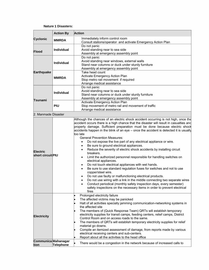
Nature 1 Disasters:
Cyclonic
Action By Action
MMRDA � Immediately inform control room� Consult stations/operator and activate Emergency Action Plan
Flood
Individual � Do not panic � Avoid standing near to sea side � Assembly at emergency assembly point
Earthquake
Individual
� Do not panic � Avoid standing near windows, external walls � Stand near columns or duck under sturdy furniture � Assembly at emergency assembly point
MMRDA
� Take head count � Activate Emergency Action Plan � Stop metro rail movement if required � Arrange medical assistance
Tsunami
Individual
� Do not panic � Avoid standing near to sea side � Stand near columns or duck under sturdy furniture � Assembly at emergency assembly point
PIU � Activate Emergency Action Plan � Stop movement of metro rail and movement of traffic � Arrange medical assistance
2. Manmade Disaster
Electric short circuit
PIU
Although the chances of an electric shock accident occurring is not high, once theaccident occurs there is a high chance that the disaster will result in casualties andproperty damage. Sufficient preparation must be done because electric shockaccidents happen in the blink of an eye – once the accident is detected it is usuallytoo late
General Prevention Measures: Do not expose the live part of any electrical appliance or wire. Be sure to ground electrical appliances. Reduce the severity of electric shock accidents by installing circuit
breakers. Limit the authorized personnel responsible for handling switches on
electrical appliances. Do not touch electrical appliances with wet hands. Be sure to use standard regulation fuses for switches and not to use
copper/steel wire. Do not use faulty or malfunctioning electrical products. Do not use wiring with a link in the middle connecting two separate wires Conduct periodical (monthly safety inspection days, every semester)
safety inspections on the necessary items in order to prevent electrical fires
Electricity
Prolonged electricity failure The affected victims may be panicked Halt of all activities specially jamming communication-networking systems in
the affected site The members of (Quick Response Team) QRTs will establish temporary
electricity supplies for transit camps, feeding centers, relief camps, District Control Room and on access roads to the same.
The members of QRTs will establish temporary electricity supplies for relief material go downs.
Compile an itemized assessment of damage, from reports made by various electrical receiving centers and sub-centers.
Report about all the activities to the head office Communication
Mahanagar Telephone There would be a congestion in the network because of increased calls to

7-15 | P a g e
Nigam Limited (MTNL)
control rooms due to panic created in the community, The initial reports on damage may not give a clear picture of the extent of
damageto communication network, The affected site may cut off from the state control rooms and the officials on
site and find difficulty in communicating to the District/State EOC.
Water Supply
PIU
Existing water storage bodies will be damaged and unusable. There would be an urgent need of water to assist victims in rescue operation. Break down of sanitation system Contamination of water due to outflow from sewers or due to breakage of
water pipelines. Identify unacceptable water sources and take necessary precautions to ensure
that no water is accessed from such sources, either by sealing sucharrangements or by posting the department guards.
Arrange for alternate water supply and storage in all transit camps, feeding centers, relief camps, cattle camps, and also the affected areas, till normalwater supply is restored.
Ensure that potable water supply is restored as per the standards andprocedures laid down in “Standards for Potable Water
Debris and Road Clearance
PIU
Access to disaster-affected area would depend upon the re-establishment of ground and water routes
Undertake construction of temporary roads to serve as access to temporarytransit and relief camps, and medical facilities for disaster victims.
Repairing of all paved and unpaved road surfaces including edge metalling,pothole patching and any failure of surface, foundations in the affected areasby maintenance engineer's staff and keep monitoring their conditions
Transport PIU
Transport should ensure smooth transportation links at state and district level.Within the disaster context, quick and safe movement of material and humans area priority. It should coordinate the use of transportation resources to support the needs of emergency support forces requiring transport capacity to perform theiremergency response, recovery and assistance missions
Relief (Food & shelter)
PIU
In the event of a disaster there would be a need of disbursing relief materials due to massive destruction of life and property taken place. The ESF on Relief shouldensure coordination of activities involving with the emergency provisions oftemporary shelters, emergency mass feeding and bulk distribution of relief suppliesto the disaster victims as also the disaster managers and relief workers. Initiate, direct and market procurement of food available from different
inventories and ensuring food supplies to the affected population Preparing take-home food packets for the families Ensuring distribution of relief material to the all the people including vulnerable
groups of the target area such as women with infants, pregnant women,children, aged people and handicapped.
Addressing Health related issues
PIU
Ensure sufficient stock of emergency medicines, antidotes, etc in all hospitalsat district and taluka level.
Keep all hospitals on ready position with manpower and medicines to addressany emergency situation.
Ensure that the required medical assistance/aid and medicines/antidotes are provided to the affected people at site as well as at evacuation/relief centers inthe affected area and necessary records are maintained.
Contact with State authority for any additional help like doctors, medicines,equipment etc.
Mobilize doctors/paramedics If required, from one district/taluka to other
7.3.7 District Disaster Management Authority
The District Disaster Management Authority shall act as the district planning, coordinating and
implementing body for disaster management and take all measures for the purpose of disaster
management in the district in accordance with the guidelines laid down by National and State
Authorities.


i | P a g e
TABLE OF CONTENTS
CHAPTER - 8: PROJECT BENEFITS .................................................................................................. 8-1
8.1 GENERAL ANALYSIS ........................................................................................................ 8-1
8.2 POSITIVE IMPACTS .......................................................................................................... 8-2
8.3 NEGATIVE IMPACTS ......................................................................................................... 8-2
8.4 EMPLOYMENT POTENTIAL .............................................................................................. 8-3
8.5 OTHER TANGIBLE BENEFITS ........................................................................................... 8-3


8-1 | P a g e
CHAPTER - 8: PROJECT BENEFITS
A benefit-cost analysis is a systematic evaluation of the economic advantages (benefits) and
disadvantages (costs) of a set of investment alternatives. The objective of a benefit-cost analysis
is to translate the effects of an investment into monetary terms and to account for the fact that
benefits generally accrue over a long period of time while capital costs are incurred primarily in
the initial years. The primary transportation-related elements that can be monetized are travel
time costs, vehicle operating costs, safety costs, ongoing maintenance costs, and remaining
capital value (a combination of capital expenditure and salvage value). For some kinds of
projects, such as bypasses, travel times and safety may improve, but operating costs may
increase due to longer travel distances. A properly conducted benefit-cost analysis would
indicate whether travel time and safety savings exceed the costs of design, construction, and the
long-term increased operating costs.
Benefit-cost analyses have been used as a tool by project managers to help evaluate preliminary
concepts during early planning studies, to evaluate alternatives and select a Preferred Alternative
as part of project environmental documentation, and to evaluate potential design and
construction staging options as part of detailed design and/or construction. A benefit-cost
analysis provides monetary measure of the relative economic desirability of project alternatives,
but decision-makers often weigh the results against other non-monetized effects and impacts of
the project.
This chapter provides project benefits, particularly on social and environmental aspects, from
implementation of the project. Positive and negative aspects of the project have been discussed
detailed in following paragraph.
8.1 GENERAL ANALYSIS
i) Travel-Time Savings
Travel-time savings typically generate the greatest amount of benefit. These savings are
calculated based on the difference in travel time between the Base Case and an alternative.
Travel time is often expressed as vehicle-hours traveled (VHT) and can be estimated using
computer models, spreadsheets, and/or travel time runs, depending on the level of analysis
needed and data availability.
The estimation of travel time savings should include both the driver and passengers in the
vehicle (i.e., vehicle occupancy rates). In many cases, vehicle occupancy rates vary between
peak and off-peak hours as well as between alternatives. Several vehicle occupancy rates may
be used to represent different conditions.
The valuation of travel time savings is calculated using standardized cost-per-hour-per-person
figures for different vehicles.
ii) Vehicle Operating Cost Savings
When transportation improvements are made, the cost of operating vehicles along a particular
facility or set of facilities can change. Operating costs can change because the number of miles
driven changes, as in the case of a shorter bypass or a reduction in circuitry or diversion of trips,

8-2 | P a g e
or it can change because of changes in the number of stops or speed-cycle changes.
The number of vehicle-miles traveled (VMT) is the most common variable that affects vehicle
operating costs. Once the change in vehicle miles is estimated, the valuation of vehicle operating
costs is calculated using standardized cost-per-mile figures for different vehicles (auto or truck).
However, if significant benefits are expected from other types of changes in travel characteristics,
such as reducing the number of vehicle stops, reducing the number of speed-cycle changes, and
possibly changes in pavement condition, those benefits can also be estimated.
iii) Safety Benefits
Safety benefits are one of the principal benefits that can result from transportation improvements.
Benefits occur when the number of crashes is reduced and/or the severity of the crashes is
reduced on a facility or set of facilities because of the transportation improvement. Standard
engineering methods can be used to evaluate both the potential crash reductions and/or changes
in severity.
8.2 POSITIVE IMPACTS
Key long-term environmental and social benefits from the project will arise mainly from traditional
sources, viz:
savings in travel times – from faster vehicle speeds and reductions in congestion of Greater
Mumbai-Navi Mumbai the projected overall savings in travel time and fuel consumption and
it will also reduce the emission of dust;
reduced cargo delays – from faster vehicle speeds and reductions in travel time;
reduced vehicle operating costs – from improved riding surfaces;
reduced road maintenance costs – from higher quality infrastructure;
reduction in exhaust emission-
reduced accidents – mainly as a result of reduced travel time and congestion but also
because of the provision of safety infrastructure and warning signs, though this latter
element was impossible to quantify – it was, however, estimated that the benefits from a
50% reduction in accidents; and
A large volume of generated traffic is, however, also forecast. This is traffic stimulated by the
reduction in travel costs and associated with new economic development. The benefits
calculated subsume the benefits from:
improved access to the Greater Mumbai, Bhiwanid, Panvel, JNPT,
new businesses, including that from increased passing trade
8.3 NEGATIVE IMPACTS
The key negative, permanent and irreversible impacts will occur along the proposed alignment
and will be:
loss of forest land

8-3 | P a g e
loss of trees and mangroves
loss of agricultural land
a marginal reduction in aesthetic beauty
diversion of Sanjay Gandhi National Park land
acquisition of private land
demolition of structure falling within the proposed corridor
All the trees felled due to this project will be compensated to reduce the negative impact of the
area.
8.4 EMPLOYMENT POTENTIAL
During construction work large number of local people will be employed in construction work from
the contractor. Local machinery, vehicle will also get engaged in construction work. Both skilled
and non skilled labors will be benefited with the implementation of this project.
During operation skilled people will need to be employed for metro operation and maintenance
8.5 OTHER TANGIBLE BENEFITS
Other tangible benefits associated with the project are:
Project will help in ribbon development along the project corridor
Enhance the connectivity of corridor side villages and markets
Enhance the local employment opportunity along with various developmental works
Reduce the travel time and exhaust emission to the local environment
Improve the drainage condition along the project corridor
Addition plantation/landscaping along the corridor will enhance the aesthetic beauty of the
area.


i | P a g e
TABLE OF CONTENTS
CHAPTER - 9: ENVIRONMENTAL BENEFIT ANALYSIS .................................................................... 9-1
9.1 CONSTRUCTION RELATED ENVIRONMENTAL MITIGATION COSTS ........................... 9-1
9.2 CONSTRUCTION / OPERATION RELATED MONITORING COSTS ................................ 9-2
LIST OF TABLES
Table 9.1: Environmental Budget for various Environmental Management Measures ............................. 9-3
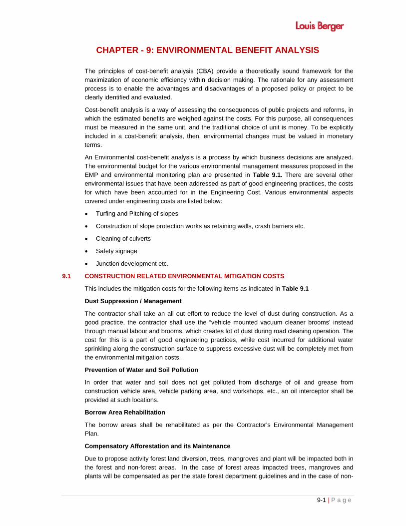
9-1 | P a g e
CHAPTER - 9: ENVIRONMENTAL BENEFIT ANALYSIS
The principles of cost-benefit analysis (CBA) provide a theoretically sound framework for the
maximization of economic efficiency within decision making. The rationale for any assessment process is to enable the advantages and disadvantages of a proposed policy or project to be clearly identified and evaluated.
Cost-benefit analysis is a way of assessing the consequences of public projects and reforms, in which the estimated benefits are weighed against the costs. For this purpose, all consequences
must be measured in the same unit, and the traditional choice of unit is money. To be explicitly
included in a cost-benefit analysis, then, environmental changes must be valued in monetary terms.
An Environmental cost-benefit analysis is a process by which business decisions are analyzed.
The environmental budget for the various environmental management measures proposed in the
EMP and environmental monitoring plan are presented in Table 9.1. There are several other environmental issues that have been addressed as part of good engineering practices, the costs
for which have been accounted for in the Engineering Cost. Various environmental aspects covered under engineering costs are listed below:
Turfing and Pitching of slopes
Construction of slope protection works as retaining walls, crash barriers etc.
Cleaning of culverts
Safety signage
Junction development etc.
9.1 CONSTRUCTION RELATED ENVIRONMENTAL MITIGATION COSTS
This includes the mitigation costs for the following items as indicated in Table 9.1
Dust Suppression / Management
The contractor shall take an all out effort to reduce the level of dust during construction. As a good practice, the contractor shall use the “vehicle mounted vacuum cleaner brooms’ instead
through manual labour and brooms, which creates lot of dust during road cleaning operation. The cost for this is a part of good engineering practices, while cost incurred for additional water
sprinkling along the construction surface to suppress excessive dust will be completely met from
the environmental mitigation costs.
Prevention of Water and Soil Pollution
In order that water and soil does not get polluted from discharge of oil and grease from
construction vehicle area, vehicle parking area, and workshops, etc., an oil interceptor shall be
provided at such locations.
Borrow Area Rehabilitation
The borrow areas shall be rehabilitated as per the Contractor’s Environmental Management Plan.
Compensatory Afforestation and its Maintenance
Due to propose activity forest land diversion, trees, mangroves and plant will be impacted both in the forest and non-forest areas. In the case of forest areas impacted trees, mangroves and plants will be compensated as per the state forest department guidelines and in the case of non-


9-2 | P a g e
forest areas trees or plants will be compensated by the district/competent authority as per their evaluation. Thus, afforestation work along the available land within ROW shall be carried out to
enhance the environmental quality as well as aesthetics of the project areas.
Environmental Enhancement Measures
In general environmental enhancement measures such as landscaping, selective tree planting,
improvement of the natural resources for the local population (provision of fodder, fuel wood, etc. by careful selection of species to be planted within the RoW) etc. shall be carried out to improve
the aesthetics in the project area. Environmental enhancement measures pertaining to Bus
Shelter / Bus Bay, Truck terminals, and Junction improvement should be provided as per engineering designs.
Waste Disposal
Disposal of waste shall be carried out as per the Contractor’s Environmental Management Plan
and waste disposal guideline.
Site Restoration
Restoration of construction sites such as diversions, workers camps (with respect to drainage arrangements, sanitation and storage area), and at construction yards shall be taken up once the
works at such locations have been completed as per the Contractor’s Site Restoration Plan and
Environmental Management Plan.
9.2 CONSTRUCTION / OPERATION RELATED MONITORING COSTS
This includes the mitigation costs for the following items as indicated in Table 9.1
Air Quality
Air quality parameters such as PM2.5, PM10, SO2, NOx, CO shall be monitored at hot-mix plant / batching plant locations at stretches of the project road where construction is in progress. During
operational stage the same parameters shall be measured at locations as given in chapter- 3 or as advised by EO-IC.
Water Quality
Water quality parameters such as pH, BOD, COD, TDS, TSS, DO, Oil and grease and Pb etc. shall be monitored as indicated in chapter-3 or at other locations as advised by the EO Independent Consultant (IC).
Noise Levels
Noise quality parameters during construction stage will be monitored at equipment yards and at other locations as indicated in Chapter-3 or as advised by the EO of the IC.
Soil Erosion
During construction, parameters such as turbidity in storm water, silt load in pond/rivers as listed in chapter-3 shall be monitored as directed in the monitoring plan. Similarly during operational
stage the same parameters shall be monitored.

9-3 | P a g e
Table 9.1: Environmental Budget for various Environmental Management Measures
Component Stage Item Unit Unit Cost (Rs.) Quantity Total Cost (INR)
(A) Mitigation cost
Air Construction
Dust Management with
sprinkling of water, covers
for vehicles transporting
construction material
Km 1,25,000.00 About 80kms 10000000.00
Water Pre-
Construction
Relocation of tub wells No. - -
covered in
Engineering and
R&R Cost
Combined oil &
Sedimentation chambers No. 1,00,000.00 2 200000.00
Rain Water harvesting pit at
the interval of 500m
covered in
Engineering Cost
Oil Interceptors at Vehicle
parking areas No. 20,000.00 4 80000.00
Flora Construction
Cost of Forest land.(NPV) ha
To be estimated
by Forest
Department
Cost of Compensatory
afforestation ha
To be estimated
by Forest
Department
Cost of Avenue plantation
along the MMC (per km 400
plants 400x75km=30,000
plants)
No. 1500.00 75km 44400000.00
Median shrub plantation No. 300.00 70km 31500000.00
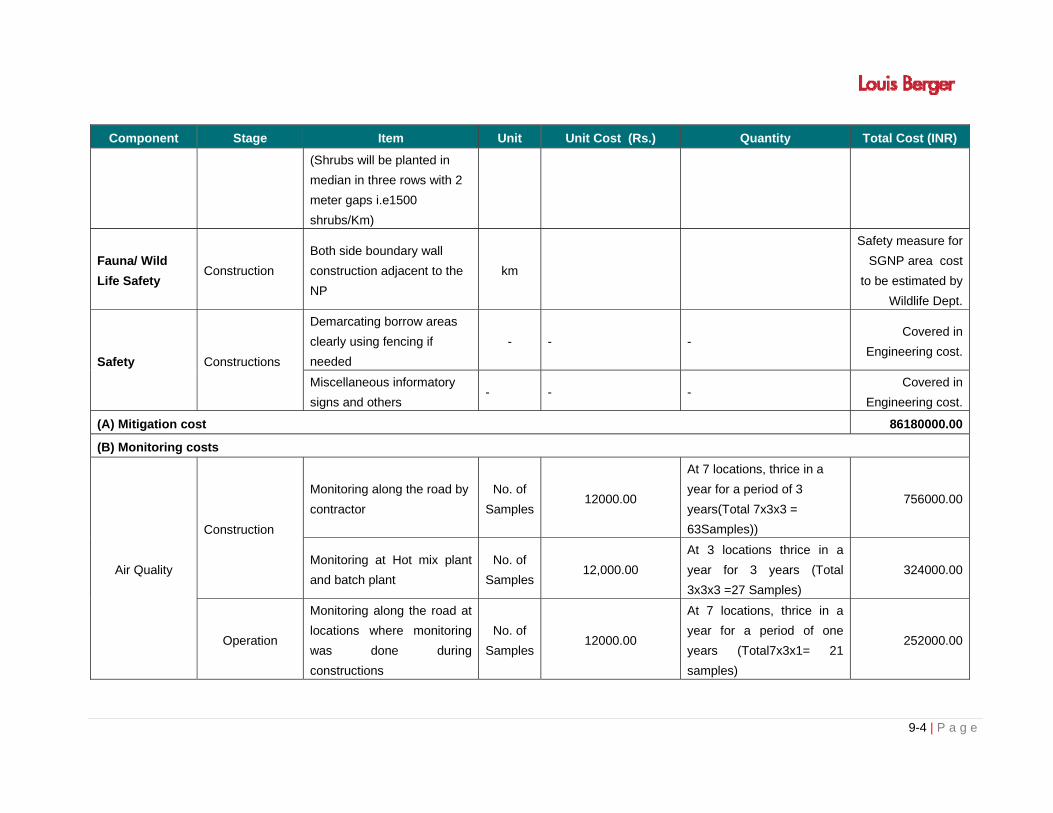
9-4 | P a g e
Component Stage Item Unit Unit Cost (Rs.) Quantity Total Cost (INR)
(Shrubs will be planted in
median in three rows with 2
meter gaps i.e1500
shrubs/Km)
Fauna/ Wild
Life Safety Construction
Both side boundary wall
construction adjacent to the
NP
km
Safety measure for
SGNP area cost
to be estimated by
Wildlife Dept.
Safety Constructions
Demarcating borrow areas
clearly using fencing if
needed
- - - Covered in
Engineering cost.
Miscellaneous informatory
signs and others - - -
Covered in
Engineering cost.
(A) Mitigation cost 86180000.00
(B) Monitoring costs
Air Quality
Construction
Monitoring along the road by
contractor
No. of
Samples12000.00
At 7 locations, thrice in a
year for a period of 3
years(Total 7x3x3 =
63Samples))
756000.00
Monitoring at Hot mix plant
and batch plant
No. of
Samples12,000.00
At 3 locations thrice in a
year for 3 years (Total
3x3x3 =27 Samples)
324000.00
Operation
Monitoring along the road at
locations where monitoring
was done during
constructions
No. of
Samples12000.00
At 7 locations, thrice in a
year for a period of one
years (Total7x3x1= 21
samples)
252000.00

9-5 | P a g e
Component Stage Item Unit Unit Cost (Rs.) Quantity Total Cost (INR)
Water Quality
Construction
Drinking water quality
monitoring of labour camps/
works site
No. of
Samples15000.00
At 4 location, Thrice in a
year for 3 years(Total 4x3x3
= 36 samples)
540000.00
Monitoring along the road at
locations (Surface Water
Quality
15000.00
At 4 location, Thrice in a
year for 3 years(Total 4x3x3
= 36 samples)
540000.00
Monitoring along the road at
locations (Ground Water
Quality
15000.00
At 6 locations thrice in a
year for 3 years (Total
6x3x3=54 samples)
810000.00
Operation
Monitoring along the road at
locations where monitoring
was done during
constructions
No. of
Samples15000.00
At 10 locations thrice in a
year for 1 year (Total
10x3x1 = 30samples)
450000.00
Noise Quality
Construction
Monitoring along the Hot mix
plant and Batch plant
No. of
Samples2500
At 4 location, Thrice in a
year for 3 years (Total
4x3x3 =36Samples)
90000
Monitoring along the Hot mix
plant and Batch plant
No. of
Samples2500
At 7 locations, Thrice in a
year for 3 years (Total
7x3x3 =63 Samples)
157500
Operation
Monitoring along the road at
locations where monitoring
was done during
constructions
No, of
Samples2500
At 7 locations, Thrice in a
year for 1 years (Total
7x3x1 =21 Samples)
52500
Soil Quality Construction Monitoring along hot mix
plant and batch plant
No of
Samples8000
At 3 locations, thrice in a
year for 3 years (Total
3x3x3 = 27 samples)
216000
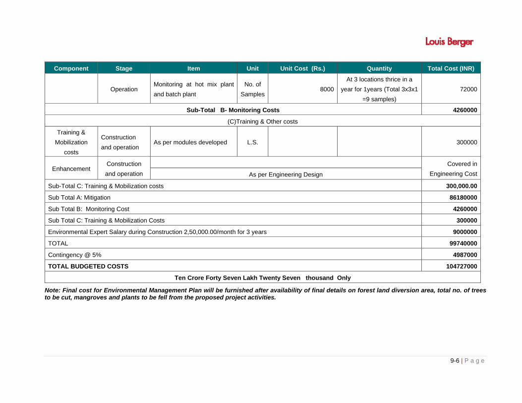
9-6 | P a g e
Component Stage Item Unit Unit Cost (Rs.) Quantity Total Cost (INR)
Operation Monitoring at hot mix plant
and batch plant
No. of
Samples8000
At 3 locations thrice in a
year for 1years (Total 3x3x1
=9 samples)
72000
Sub-Total B- Monitoring Costs 4260000
(C)Training & Other costs
Training &
Mobilization
costs
Construction
and operation As per modules developed L.S. 300000
Enhancement Construction
and operation
Covered in
Engineering CostAs per Engineering Design
Sub-Total C: Training & Mobilization costs 300,000.00
Sub Total A: Mitigation 86180000
Sub Total B: Monitoring Cost 4260000
Sub Total C: Training & Mobilization Costs 300000
Environmental Expert Salary during Construction 2,50,000.00/month for 3 years 9000000
TOTAL 99740000
Contingency @ 5% 4987000
TOTAL BUDGETED COSTS 104727000
Ten Crore Forty Seven Lakh Twenty Seven thousand Only
Note: Final cost for Environmental Management Plan will be furnished after availability of final details on forest land diversion area, total no. of trees to be cut, mangroves and plants to be fell from the proposed project activities.


i | P a g e
TABLE OF CONTENTS
CHAPTER - 10: ENVIRONMENTAL MANAGEMENT PLAN ............................................................... 10-1
10.1 PRE-CONSTRUCTION STAGE ............................................................................................... 10-1
10.1.1 Pre-construction activities by PIU/ Independent Consultant ......................................... 10-1
10.1.2 Pre-construction activities by Contractor ...................................................................... 10-1
10.2 CONSTRUCTION STAGE ........................................................................................................ 10-2
10.2.1 Construction activities by the Contractor ...................................................................... 10-2
10.2.2 Construction activities by the PIU/Independent Consultants ........................................ 10-2
10.3 OPERATION STAGE ............................................................................................................... 10-2
LIST OF TABLES
Table 10.1: Generic Environmental Management Plan ........................................................................ 10-3
Table 10.2: Environmental Management Plan for Operation Phase ................................................... 10-27

10-1 | P a g e
CHAPTER - 10: ENVIRONMENTAL MANAGEMENT PLAN
An important objective of environmental assessment is to develop procedures and plans to
ensure that the mitigation measures and monitoring requirements shall be approved during the
environmental compliance review will actually be carried out in subsequent stages of the project.
As a result, preparation of EMPs during project processing and on setting out conditions and
targets to be met during project Implementation.
The environmental management measures shall be implemented during the various stages of
the project viz: Pre-construction stage, Construction Stage and Operational Stage. The
environmental management plan is as described below.
Environmental Management Plan (EMP)
Objectives of EMP
The Environmental Management Plan (EMP) consists a set of mitigation, monitoring and
institutional measures to be taken during the design, construction and operational phases of the
project to eliminate adverse environmental impacts, to offset them, or to reduce them to
acceptable levels. The main aim of the Environmental Management Plan is to ensure that the
various adverse impacts are mitigated and the positive impacts are enhanced. The objectives of
the EMP at various stages of the project planning and implementation are as follows:
A description of the various management measures suggested during different stages of
proposed project (viz. Construction and operation) is provided in Table 10.1 and Table 10.2
respectively.
10.1 PRE-CONSTRUCTION STAGE
10.1.1 Pre-construction activities by PIU/ Independent Consultant
Prior to the contractors mobilization, the MMRDA will ensure that an encumbrance free Corridor
of Impact is handed over to enable the start of construction. Clearance involves the following
activities:
Removal and felling of trees at very minimal possible level.
Relocation of common property resources and community assets like telephone poles,
electric poles and hand pumps will be impacted.
Formal arrangements for maintenance of enhancement sites. This includes plantation of
trees and barricades along the highway.
Modification (if any), of the contract documents by the Engineer of the MMRDA/PIU
NOC/Clearance related to the project such as wildlife/forest/EC etc.
10.1.2 Pre-construction activities by Contractor
Pre-construction stage involves mobilisation of the contractor and the activities undertaken
by the contractor pertaining to the planning of logistics and site preparation necessary for
commencing construction activities. The activities include:

10-2 | P a g e
Joint field verification of EMP by the Environment Specialist of the Independent Consultant
and Contractor.
Identification and selection of material sources (quarry and borrow material, water, sand etc).
Procurement of construction equipment / machinery such as crushers, hot mix plants,
batching plants and other construction equipment and machinery.
Selection, design and layout of construction areas, hot mix and batching plants, labour
camps etc.
Apply for and obtain all the necessary clearances/ NOC,s/ consents from the agencies
concerned.
Planning traffic diversions and detours including arrangements for temporary land
acquisition.
10.2 CONSTRUCTION STAGE
10.2.1 Construction activities by the Contractor
Construction stage is the most crucial stage in terms of activities that require careful
management to avoid environmental impacts.
There are several other environmental issues that have been addressed as part of good
engineering practices, the costs for which have been accounted for in the Engineering Costs.
They include providing roadside drainage, provision of cross drainage structures etc.
10.2.2 Construction activities by the PIU/Independent Consultants
The PIU/Independent Consultant shall be involved in the smooth execution of the project and
assisting the contractor during this phase. Their work shall include but not limited to:
Monitoring and guiding the contractor on adopting good environmental and engineering
practices.
Arrangement of plantation through the Forest Department
Arranging training to the contractor and other stakeholders according to the needs arising.
Making changes in the design if need arises
10.3 OPERATION STAGE
The operational stage involves the following activities by PIU:
Monitoring of environmental conditions through approved monitoring agency.
Monitoring of operational performance of the various mitigation/enhancement measures
carried out.

10-3 | P a g e
Table 10.1: Generic Environmental Management Plan
Sl. No. Environmental Issue Management Measures Reference Location Responsibility
Planning and Execution
Supervision/ Monitoring
PRE-CONSTRUCTION STAGE
Pre-construction activities by PIU
P.1 Alignment, Width of the MMC and religious structures
The proposed corridor was selected by shifting / adjusting the centerline, adopting of suitable cross-sections and adjustment of the median width to minimize land acquisition, loss of settlements and to avoid environmentally sensitive features like PF/RF/WL/NP/religious structures etc. compatible with project activities.
The Right to Fair Compensation and Transparency in Land Acquisition, Rehabilitation and Resettlement Act 2013, And Maharashtra Regional and Town Planing Act,1966 FCA-1980,WLPA-1972
Throughout out Corridor
PIU, Revenue Dept., NGOs, Collaborating Agencies
EO-IC (Independent Consultant)
P.2 Land Acquisition
The acquisition of land and private properties will be carried out in accordance with the RAP and entitlement framework for the project. It will be ensured that all R & R activities including implementation of Environment Management Plan are completed before the start of work. PIU has to ascertain that any additional environmental impacts resulting from acquisition of land are addressed and integrated into the EMP and other relevant documents.
The Right to Fair Compensation and Transparency in Land Acquisition, Rehabilitation and Resettlement Act 2013, And Maharashtra Regional and Town Planing Act,1966
Throughout out Corridor
PIU, Revenue Dept., NGOs, Collaborating Agencies
EO-IC
P.3 Preservation of Trees
All efforts will be made to preserve trees including evaluation of minor design adjustments/ alternatives to save trees. Specific attention will be given for protecting giant trees, and locally important trees (religiously important etc.).
Clause No. 201.2 MORT&H Specifications for Road and Bridge
Throughout out Corridor
PIU, Forest Department, Contractor
EO-IC

10-4 | P a g e
Sl. No. Environmental Issue Management Measures Reference Location Responsibility
Planning and Execution
Supervision/ Monitoring
Tree cutting is to proceed only after all the legal requirements including attaining of In-principle and Formal Clearances from the Forest Dept. / DoEF/ MoEF & CC and after permission of local authority are completed and subsequently a written order is issued to the Contractor. Particular species declared as ‘protected’ by the State’s Forest Dept. in the private land will be felled only after due clearance from the Forest Dept./ concerned agencies is obtained. In the event of design changes, additional assessments including the possibility to save trees shall be made. Stacking, transport and storage of the wood will be done as per the relevant norms. Systematic corridor level documentation for the trees cut and those saved will be maintained with “EO-IC”.
works Table 3.14, of Chapter 3,
P.4
Relocation of Community Utilities and Common Property Resources
All community utilities and properties i.e., water supply lines, sewer lines, hand pumps will be relocated before construction starts, on any section of the project corridor. The PIU will relocate these properties in consultation and written agreement with the agency/ owner/community. Environmental considerations with suitable/required actions including health and hygiene aspects will be kept in mind while relocating all community utilities and resources.
As in RAP
Throughout out Corridor
PIU, Concerned Agencies, Contractor
EO-IC
P.5
Orientation of Implementing Agency and Contractors
The PIU shall organize orientation sessions and regular training sessions during all stages of the project. This shall include on-site training (general as well as in the specific context of a sub-project). These sessions shall involve all staff of Independent Consultants, field level implementation staff of PIU and Contractor, Environmental Experts. The contractor will ensure that his staff including engineers, supervisors and operators attend the training sessions.
Project Requirements
Throughout out Corridor
Contractor EO-IC
P.6
P.6.1 Joint Field The Environmental Expert of IC and the Contractor will carry Project Throughout Contractor/ PIU

10-5 | P a g e
Sl. No. Environmental Issue Management Measures Reference Location Responsibility
Planning and Execution
Supervision/ Monitoring
Verification out joint field verification to ascertain any additional possibility to saving trees, environmental and community resources. The verification exercise should assess the need for additional protection measures or changes in design/ scale/ nature of protection measures including the efficacy of enhancement measures suggested in the EMP. Proper documentation and justifications/reasons shall be maintained in all such cases where deviation from the original EMP is proposed.
Requirements out Corridor Environmental Expert of IC
P.6.2
Assessment of Impacts due to Changes/Revisions/Additions in the Project Work
The Environmental Expert of IC will assess impacts and revise/ modify the EMP and other required sections of the project documents in the event of changes/ revisions (including addition or deletion) in the project’s scope of work.
Project Requirements
Throughout out Corridor
Contractor/ Environmental Expert of IC
PIU
P.6.3 Crushers, hot-mix plants and Batching Plants Location
Hot mix plants and batching plants will be sited sufficiently away from settlements and agricultural operations or any commercial establishments. Such plants will be located at least 1000 m away from the nearest village/ settlement preferably in the downwind direction. The Contractor shall submit a detailed layout plan for all such sites and approval of Environmental Expert of IC shall be necessary prior to their establishment. Arrangements to control dust pollution through provision of windscreens, sprinklers, and dust encapsulation will have to be provided at all such sites. Specifications of crushers, hot mix plants and batching plants will comply with the requirements of the relevant current emission control legislations and Consent/NOC for all such plants shall be submitted to the “PIU through Independent Consultant. The Contractor shall not initiate plant/s operation till the required legal clearances are obtained and submitted. The engineer will ensure that the regulatory and legal requirements are being complied with.
Clause No 111.1 MoRT&H Air (P&CP) Act 1981,
Throughout out Corridor
Contractor Engineer, EO-IC

10-6 | P a g e
Sl. No. Environmental Issue Management Measures Reference Location Responsibility
Planning and Execution
Supervision/ Monitoring
P.6.4 Other Construction Vehicles, Equipment and Machinery
All vehicles, equipment and machinery to be procured for construction will confirm to the relevant Indian Standard (IS) norms. The discharge standards promulgated under the Environment Protection Act, 1986 will be strictly adhered to. Noise limits for construction equipments to be procured such as compactors, rollers, front loaders concrete mixers, cranes (moveable), vibrators and saws will not exceed 75 dB (A), measured at one meter from the edge of the equipment in free field, as specified in the Environment (Protection) Rules, 1986. The Contractor shall maintain a record of PUC for all vehicles and machinery used during the contract period, which shall be produced for EO - IC and PIU verification whenever required. Mobile equipment shall be placed at least 100metres away from the nearest dwelling.
Project Requirement Guideline-I
Throughout out Corridor
Contractor Engineer, EO-IC
P.7
7.1 Borrow Areas
Finalizing borrows areas for borrowing earth and all logistic arrangements as well as compliance to environmental requirements, as applicable, will be the sole responsibility of the contractor. The Contractor will not start borrowing earth from select borrow area until the formal agreement is signed between landowner and contractor and a copy is submitted to the “EO-IC/PIU through the Engineer. Locations finalized by the contractor shall be reported to the Environmental Expert of IC and who will in turn report to PIU. Planning of haul roads for accessing borrow materials will be undertaken during this stage. The haul roads shall be routed to avoid agricultural areas as far as possible (in case such a land is disturbed, the Contractor will rehabilitate it as per Borrow Area Rehabilitation Guidelines and will use the existing village roads wherever available.
Clause No. 111.2 & 305.2.2 MORT&H Specifications for Road and Bridge works Guideline-I and V Guidelines for Borrow Area Management).
Borrow Areas Contractor EO-IC, PIU

10-7 | P a g e
Sl. No. Environmental Issue Management Measures Reference Location Responsibility
Planning and Execution
Supervision/ Monitoring
In addition to testing for the quality of borrow materials by the IC, the environmental personnel of the IC will be required to inspect every borrow area location prior to approval The IC will make sure that each such site is in line with IRC and other Project Guidelines.
P.7.2 Quarry
Contractor will finalize the quarry for procurement of construction materials after assessment of the availability of sufficient materials, quality and other logistic arrangements. In case the contractor decides to use quarries other than recommended by Feasibility consultants, then it will be selected based on the suitability of the materials and as per established law. The contractor will procure necessary permission for procurement of materials from Mining Department, District Administration and State Pollution Control Board and shall submit a copy of the approval and the rehabilitation plan to the “PIU through Engineer. Contractor will also work out haul road network and report to Environmental Expert of IC and IC will inspect and in turn report to PIU before approval.
Clause No. 111.3 & MORT&H Specifications for Road and Bridge works
Along the Project Influence Area
Contractor EO-IC, PIU
P.7.3 Arrangement for Construction Water
The contractor will use ground water as a source of water for the construction and can set up the own bore well facility for construction work. To avoid disruption/disturbance to other water users, the contractor will extract water from fixed locations and consult the Environmental Expert of IC before finalizing the locations. The Contractor will provide a list of locations and type of sources from where water for construction will be used. The contractor will seek approval from the EO-IC prior to the finalization of these locations The contractor will not be allowed to pump from any irrigation canal and surface water bodies used by community. The contractor will need to comply with the requirements of
Clause No. 1010 MORT&H Specifications for Road and Bridge works EP Act 1986
Along the Project Corridor
Contractor EO-IC, PIU

10-8 | P a g e
Sl. No. Environmental Issue Management Measures Reference Location Responsibility
Planning and Execution
Supervision/ Monitoring
the State Ground Water Department and seek their approval for doing so and submit copies of the permission to IC and PIU prior to initiation of any construction work.
P.7.4 Labor Requirements The contractor preferably will use unskilled labour drawn from local communities to give the maximum benefit to the local community.
Special Conditions of Contract
Along the Project Area
Contractor EO-IC, PIU
P.7.5
Construction Camp Locations – Selection, Design and Lay-out
Siting of the construction camps will be slected by the contractor as per the guidelines. Construction camps will not be proposed within 500 m from the nearest settlements to avoid conflicts and stress over the infrastructure facilities with the local community applies only in case where a construction camp doesn’t house plant sites. Location for stockyards for construction materials will be identified at least 1000 m from watercourses. The waste disposal and sewage system for the camp will be designed, built and operated such that no odor is generated.
Guidelines II Guidelines for Siting and Layout of Construction Camp
Along the Project Corridor
Contractor EO- IC, PIU
P.7.6 Arrangements for Temporary Land Requirement
The contractor as per prevalent rules will carry out negotiations with the landowners for obtaining their consent for temporary use of lands for construction sites/hot mix plants/traffic detours/borrow areas etc. The Contractor will submit a copy of agreement to the Environment Expert of Independent Consultant. The Environmental Expert of IC will be required to ensure that the clearing up of the site prior to handing over to the owner (after construction or completion of the activity) is included in the contract.
Project Requirements
Along the Project Corridor
Contractor EO- IC, PIU
P.7.7 Implementation -Information Meetings
The contractor will organize at least 2 implementation information meetings in the vicinity of Project Site (minimum one in each section) for general public to consult and inform people about his plans covering overall construction schedule, safety, use of local resources (such as earth, water), traffic safety and management plans of debris disposal, drainage protection, canal training work during construction, pollution abetment and other plans, measures
Project Requirements
Along the Project Corridor
Contractor EO- IC, PIU

10-9 | P a g e
Sl. No. Environmental Issue Management Measures Reference Location Responsibility
Planning and Execution
Supervision/ Monitoring
to minimize disruption, damage and in convenience to roadside users and people along the road. The first Implementation information meeting be conducted within four weeks of mobilization. The people should be informed about the date, time and venue at least 7 days prior to meetings. Public shall be informed about the meeting through display of posters at prominent public places (panchayat offices, offices of Market committees, Notice board of religious places etc.) and distribution of pamphlets along roadside communities or in any manner deemed fit. The contractor will maintain a channel of communication with the communities through his designated Environment and Safety Officer to address any concern or grievances. Periodic meetings will also be conducted during the construction period to take feedback from communities or their representatives to ensure minimum disturbance. The mechanism and contents for disclosure shall be approved by PIU prior to the meetings.
CONSTRUCTION STAGE
C.1
C.1.1 Clearing and Grubbing
Vegetation will be removed from the construction zone before commencement of construction. All works will be carried out such that the damage or disruption to flora other than those identified for cutting is minimum. Only ground cover/shrubs that impinge directly on the permanent works or necessary temporary works will be removed with prior approval from the Environmental Expert of IC. The Contractor under any circumstances will not cut trees other than those identified for cutting and for which he has written instructions from the PIU. The PIU will issue these instructions only after receiving all stages of clearances from the Forest Department/ MoEF. Vegetation only with girth of over 30 cm will be considered
Clause No. 201 MORT&H Specifications for Road and Bridge works Table 3.14, of
chapter 3
Along the project Corridor work in progress
Contractor EO-IC, PIU

10-10 | P a g e
Sl. No. Environmental Issue Management Measures Reference Location Responsibility
Planning and Execution
Supervision/ Monitoring
as trees and shall be compensated, in the event of PIU’s instruction to undertake tree cutting. The sub grade of the existing pavement shall be used as embankment fill material. The existing base and sub-base material shall be recycled as sub-base of the haul road or access roads. The existing bitumen surface may be utilized for the
paving of cross roads, access roads and paving works in construction sites and campus, temporary traffic diversions, haulage routes etc.
C.1.2
Disposal of debris from dismantling structures and road surface
The contractor shall identify disposal sites. The identified locations will be reported to the Environmental Expert of IC. These locations will be checked on site and accordingly approved by Environmental Expert of IC prior to any disposal of waste materials. All arrangements for transportation during construction including provision, maintenance, dismantling and clearing debris, will be considered incidental to the work and will be planned and implemented by the contractor as approved and directed by the Environmental Expert of IC. The pre-designed disposal locations will be a part of Comprehensive Solid Waste Management Plan to be prepared by Contractor in consultation and with approval of Environmental Expert of IC. Debris generated from pile driving or other construction activities shall be disposed such that it does not flow into the surface water bodies or form mud puddles in the area.
Clause No. 201.4 MORT&H Specifications for Road and Bridge works
Along the project Corridor work in progress
Contractor EO- IC, PIU
C.1.3 Other Construction Wastes Disposal
The pre-identified disposal locations will be a part of Comprehensive Waste Disposal Management Plan to be prepared by the Contractor in consultation and with approval of Environmental Expert of IC. Location of disposal sites will be finalized prior to initiation of works on any particular section of the road. The Environmental Expert of IC will approve these disposal sites after conducting a joint inspection on the site with the
Clause No. 301.3.2 MORT&H Specifications for Road and Bridge works
Along the Project Corridor
Contractor EO- IC, PIU

10-11 | P a g e
Sl. No. Environmental Issue Management Measures Reference Location Responsibility
Planning and Execution
Supervision/ Monitoring
Contractor. Contractor will ensure that any spoils of material unsuitable for embankment fill will not be disposed off near any water course, agricultural land, and natural habitat like grass lands or pastures. Such spoils from excavation can be used to reclaim borrow pits and low-lying areas located in barren lands along the project corridors (if so desired by the owner/community and approved by the Environment Expert IC). Non-bituminous wastes other than fly ash may be dumped in borrow pits (preferably located in barren lands) covered with a layer of the soil. No new disposal site shall be created as part of the project, except with prior approval of the Environmental Expert of IC. All waste materials will be completely disposed and the site will be fully cleaned and certified by Environmental Expert of IC before handing over. The contractor at its cost shall resolve any claim, arising out of waste disposal or any non-compliance that may arise on account of lack of action on his part.
C.1.4 Stripping, stocking and preservation of top soil
The topsoil from all areas of cutting and all areas to be permanently covered will be stripped to a specified depth of 150 mm and stored in stockpiles. A portion of the temporarily acquired area and/or Right of Way will be earmarked for storing topsoil. The locations for stock piling will be pre-identified in consultation and with approval of Environmental Expert of IC. The following precautionary measures will be taken to preserve them till they are used: Stockpile will be designed such that the slope does not exceed 1:2 (vertical to horizontal), and height of the pile is restricted to 2 m. To retain soil and to allow percolation of water, silt fencing will protect the edges of the pile. Stockpiles will not be surcharged or otherwise loaded and multiple handling will be kept to a minimum to ensure that no compaction will occur. The stockpiles shall be covered with
Clause No. 301.2.2 MORT&H Specifications for Road and Bridge works
Along the Project Corridor
Contractor EO- IC, PIU

10-12 | P a g e
Sl. No. Environmental Issue Management Measures Reference Location Responsibility
Planning and Execution
Supervision/ Monitoring
gunny bags or vegetation. It will be ensured by the contractor that the topsoil will not be unnecessarily trafficked either before stripping or when in stockpiles. Such stockpiled topsoil will be utilized for - covering all disturbed areas including borrow areas only in case where these are to be rehabilitated as farm lands (not those in barren areas) top dressing of the road embankment and fill slopes filling up of tree pits, in the median and In the agricultural fields of farmers, acquired temporarily. Residual topsoil, if there is any will be utilized for the plantation at median and side of the main carriageway.
C.1.5 Accessibility
The contractor will provide safe and convenient passage for vehicles, pedestrians and livestock to and from roadsides and property accesses connecting the project corridor, providing temporary connecting road. The Contractor will take care that Schools and religious places are accessible to Public. The contractor will also ensure that the work on / at existing accesses will not be undertaken without providing adequate provisions and to the prior satisfaction of Environmental Expert of IC. The contractor will take care that the cross roads are constructed in such a sequence that construction work over the adjacent cross roads are taken up one after one so that traffic movement in any given area not get affected much.
Along the Project Corridor
Contractor EO- IC, PIU
C.1.6 Planning for Traffic Diversions and Detours
Temporary diversions will be constructed with the approval of the Resident Engineer and Environmental Expert of IC for which contractor will seek prior approval for such plans. Detailed Traffic Control Plans will be prepared and submitted to the Resident Engineer for approval, seven days prior to commencement of works on any section of road. The traffic control plans shall contain details diversions; traffic safety arrangement during construction; safety measures for night
Clause No. 112 MORT&H Specifications for Road and Bridge works IRC; SP 55 Guideline-VII Guidelines for
Along the Project Corridor
Contractor EO- IC, PIU
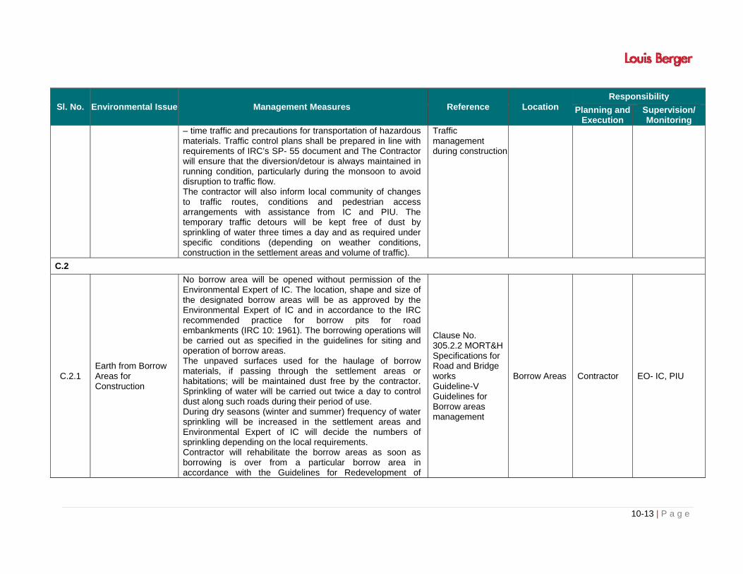
10-13 | P a g e
Sl. No. Environmental Issue Management Measures Reference Location Responsibility
Planning and Execution
Supervision/ Monitoring
– time traffic and precautions for transportation of hazardous materials. Traffic control plans shall be prepared in line with requirements of IRC’s SP- 55 document and The Contractor will ensure that the diversion/detour is always maintained in running condition, particularly during the monsoon to avoid disruption to traffic flow. The contractor will also inform local community of changes to traffic routes, conditions and pedestrian access arrangements with assistance from IC and PIU. The temporary traffic detours will be kept free of dust by sprinkling of water three times a day and as required under specific conditions (depending on weather conditions, construction in the settlement areas and volume of traffic).
Traffic management during construction
C.2
C.2.1 Earth from Borrow Areas for Construction
No borrow area will be opened without permission of the Environmental Expert of IC. The location, shape and size of the designated borrow areas will be as approved by the Environmental Expert of IC and in accordance to the IRC recommended practice for borrow pits for road embankments (IRC 10: 1961). The borrowing operations will be carried out as specified in the guidelines for siting and operation of borrow areas. The unpaved surfaces used for the haulage of borrow materials, if passing through the settlement areas or habitations; will be maintained dust free by the contractor. Sprinkling of water will be carried out twice a day to control dust along such roads during their period of use. During dry seasons (winter and summer) frequency of water sprinkling will be increased in the settlement areas and Environmental Expert of IC will decide the numbers of sprinkling depending on the local requirements. Contractor will rehabilitate the borrow areas as soon as borrowing is over from a particular borrow area in accordance with the Guidelines for Redevelopment of
Clause No. 305.2.2 MORT&H Specifications for Road and Bridge works Guideline-V Guidelines for Borrow areas management
Borrow Areas Contractor EO- IC, PIU

10-14 | P a g e
Sl. No. Environmental Issue Management Measures Reference Location Responsibility
Planning and Execution
Supervision/ Monitoring
Borrow Areas or as suggested by Environmental Expert of IC. The final rehabilitation plans will be approved by the Environmental Expert of the IC.
C.2.2 Quarry Operations
The contractor shall obtain materials from quarries only after the consent of the Department of Mining / SPCB (both the states) / District Administration or will use existing approved sources of such materials. Copies of consent/ approval/ rehabilitation plan for opening a new quarry or use of an existing quarry source will be submitted to Environment Expert IC and the Resident Engineer. The contractor will develop a Comprehensive Quarry Redevelopment plan, as per the Mining Rules of the state and submit a copy to PIU and IC prior to opening of the quarry site. The quarry operations will be undertaken within the rules and regulations in force in the state.
Clause No. 111.3 MORT&H Specifications for Road and Bridge works Guidelines VI Guideline for Quarry Management
Quarry Areas Contractor EO- IC, PIU
C.2.3
Transporting Construction Materials and Haul Road Management
Contractor will maintain all roads (existing or built for the project), which are used for transporting construction materials, equipment and machineries as précised. All vehicles delivering fine materials to the site will be covered to avoid spillage of materials. All existing highways and roads used by vehicles of the contractor or any of his sub-contractor or suppliers of materials and similarly roads, which are part of the works, will be kept clear of all dust/mud or other extraneous materials dropped by such vehicles. Contractor will arrange for regular water sprinkling as necessary for dust suppression of all such roads and surfaces with specific attention to the settlement areas. The unloading of materials at construction sites/close to settlements will be restricted to daytime only.
Project Requirement
All Roads Used
Contractor EO- IC, PIU
C.2.4 Construction Water Contractor will arrange adequate supply and storage of water for the whole construction period at his own costs. The Contractor will submit a list of source/s from where water will
Clause No. 1010 EP Act 1986 MORT&H
Along the Project Corridor
Contractor EO- IC, PIU

10-15 | P a g e
Sl. No. Environmental Issue Management Measures Reference Location Responsibility
Planning and Execution
Supervision/ Monitoring
be used for the project to ‘PIU’ through the Engineer. The contractor will source the requirement of water preferentially from ground water but with prior permission from the Ground Water Board. A copy of the permission will be submitted to ‘PIU’ through the Engineer prior to initiation of construction. The contractor will take all precaution to minimize the wastage of water in the construction process/ operation.
Specifications for Road and Bridge works
C.3
C.3.1 Disruption to Other Users of Water
While working across or close to any perennial water bodies, contractor will not obstruct/ prevent the flow of water. Construction over and close to the non-perennial streams shall be undertaken in the dry season. If construction work is expected to disrupt users of community water bodies, notice shall be served well in advance to the affected community by the contractor. The contractor will take prior approval of the River Authority or Irrigation Department for any such activity. The PIU and the Engineer will ensure that contractor has served the notice to the downstream users of water well in advance.
Table 3.9 and 3.10 of Chapter-3
All Water Bodies
Contractor EO- IC, PIU
C.3.2 Drainage
Contractor will ensure that no construction materials like earth, stone, ash or appendage is disposed off in a manner that blocks the flow of water of any water course and cross drainage channels. Contractor will take all-necessary measures to prevent any blockage to water flow. In addition to the design requirements, the contractor will take all required measures as directed by the ‘EO-IC’ and the ‘Resident Engineer’ to prevent temporary or permanent flooding of the site or any adjacent area.
Clause No. 501.8.6 MORT&H Specifications for Road and Bridge works
Drainage line along the road
Contractor EO- IC, PIU
C.3.3
Siltation of Water Bodies and Degradation of Water Quality
The Contractor will not excavate beds of any stream/canals/ any other water body for borrowing earth for embankment construction. Contractor will construct silt fencing at the base of the embankment construction for the entire perimeter of any
Clause No. 501.8.6 MORT&H Specifications for Road and Bridge works
All Surface Water Bodies Along the Project Corridor
Contractor EO- IC, PIU

10-16 | P a g e
Sl. No. Environmental Issue Management Measures Reference Location Responsibility
Planning and Execution
Supervision/ Monitoring
water body (including wells) adjacent to the ROW and around the stockpiles at the construction sites close to water bodies. The fencing will be provided prior to commencement of earthwork and continue till the stabilization of the embankment slopes, on the particular sub-section of the road. The contractor will also put up sedimentation cum grease traps at the outer mouth of the drains located in truck lay byes and bus bays which are ultimately entering into any surface water bodies / water channels with a fall exceeding 1.5 m. in present case three Sedimentation Cum Grease Trap are proposed, However the item has been kept in case need arises during construction. Contractor will ensure that construction materials containing fine particles are stored in an enclosure such that sediment-laden water does not drain into nearby watercourse.
Water (P & CP) Act 1981 Table 3.9 of Chapter-3
C.3.4 Slope Protection and Control of Soil Erosion
The contractor will take slope protection measures as per design, or as directed by the Environmental Expert of IC to control soil erosion and sedimentation. All temporary sedimentation, pollution control works and maintenance thereof will be deemed as incidental to the earth work or other items of work and as such as no separate payment will be made for them. Contractor will ensure the following aspects: During construction activities on road embankment, the
side slopes of all cut and fill areas will be graded and covered with stone pitching, grass and shrub as per design specifications.
Turfing works will be taken up as soon as possible provided the season is favourable for the establishment of grass sods. Other measures of slope stabilization will include mulching, netting and seeding of batters and drains immediately on completion of earthworks.
In borrow pits, the depth shall be so regulated that the sides of the excavation will have a slope not steeper than 1 vertical to 2 horizontal, from the edge of the final
Clause No. 306 & 305.2.2 MORT&H Specifications for Road and Bridge works
Guideline-IX Soil Erosion & Sedimentation Control)
Along the Project Corridor
Contractor EO- IC, PIU

10-17 | P a g e
Sl. No. Environmental Issue Management Measures Reference Location Responsibility
Planning and Execution
Supervision/ Monitoring
section of the bank. Along sections abutting water bodies, stone pitching as
per design specification will protect slopes.
C.4
C.4.1
C.4.1.1 Water Pollution from Construction Wastes
The Contractor will take all precautionary measures to prevent the wastewater generated during construction from entering into streams, water bodies or the irrigation system. Contractor will avoid construction works close to the streams or water bodies during monsoon. All waste arising from the project is to be disposed off in the manner that is acceptable and as per norms of the State Pollution Control Board.
Clause No. 501.8.6 MORT&H Specifications for Road and Bridge works Water (P & CP) Act 1974
Along the Project Corridor
Contractor EO- IC, PIU
C.4.1.2 Water Pollution from Fuel and Lubricants
The contractor will ensure that all construction vehicle parking location, fuel/lubricants storage sites, vehicle, machinery and equipment maintenance and refueling sites will be located at least 500 m from rivers and irrigation canal/ponds. All location and layout plans of such sites will be submitted by the Contractor prior to their establishment and will be approved by the ‘EO-IC, PIU/ MMRDA. Contractor will ensure that all vehicle/machinery and equipment operation, maintenance and refueling will be carried out in such a fashion that spillage of fuels and lubricants does not contaminate the ground. Oil interceptors will be provided for vehicle parking, wash down and refueling areas as per the design provided. In all, fuel storage and refueling areas, if located on agricultural land or areas supporting vegetation, the top soil will be stripped, stockpiled and returned after cessation of such storage. Contractor will arrange for collection, storing and disposal of oily wastes to the pre-identified disposal sites (list to be submitted to IC and PIU) and approved by the
Clause No. 501.8.6 MORT&H Specifications for Road and Bridge works Water (P & CP) Act 1974 Guideline XI Guidelines For The Storage, Handling, Use And Emergency Response For Hazardous Chemicals
Along the Project Corridor
Contractor EO- IC, PIU

10-18 | P a g e
Sl. No. Environmental Issue Management Measures Reference Location Responsibility
Planning and Execution
Supervision/ Monitoring
Environmental Expert of IC. All spills and collected petroleum products will be disposed off in accordance with MoEF and state PCB guidelines. ‘EO-IC and Resident Engineer’ will certify that all arrangements comply with the guidelines of PCB/ MoEF or any other relevant laws.
C.4.1.3 Chemical Attack
To limit the potential chemical attack the concrete foundation should contain minimum cement concrete of 330 kg/cc For Under water concrete 10% extra cement is used. Clear Concrete cover of minimum 75mm shall be provided to under water structures.
Project Requirements
Along the Project Corridor
Contractor EO- IC, PIU
C.4.2
C.4.2.1 Dust Pollution
The contractor will take every precaution to reduce the level of dust from crushers/hot mix plants, construction sites involving earthwork by sprinkling of water, encapsulation of dust source and by erection of screen/barriers. All the plants will be sited at least 1 km in the downwind direction from the nearest human settlement. The contractor will provide necessary certificates to confirm that all crushers used in construction conform to relevant dust emission control legislation. The suspended particulate matter value at a distance of 40m from a unit located in a cluster should be less than 500 micro gram/m3. The pollution monitoring is to be conducted as per the monitoring plan. Alternatively, only crushers licensed by the SPCB shall be used. Required certificates and consents shall be submitted by the Contractor in such a case to the ‘EO-PIU’ through the ‘Engineer’. Dust screening vegetation will be planted on the edge of the RoW for all existing roadside crushers. Hot mix plant will be fitted with dust extraction units.
Clause No. 111 & 501.8.6 MORT&H Specifications for Road and Bridge works Air (P & CP) Act 1981
Along the Project Road, Construction Site/ Camps
Contractor EO- IC, PIU
C.4.2.2 Emission from Construction
Contractor will ensure that all vehicles, equipment and machinery used for construction are regularly maintained
Clause No. 501.8.6 MORT&H
Along the Project Road,
Contractor EO- IC, PIU,

10-19 | P a g e
Sl. No. Environmental Issue Management Measures Reference Location Responsibility
Planning and Execution
Supervision/ Monitoring
Vehicles, Equipment and Machineries
and confirm that pollution emission levels comply with the relevant requirements of SPCB. The Contractor will submit PUC certificates for all vehicles/ equipment/machinery used for the project. Monitoring results will also be submitted to ‘PIU’ through the ‘IC’.
Specifications for Road and Bridge works Air (P & CP)Act 1981 Central Motor & Vehicle Act 1988
all vehicles used/ Camps
C.4.3.3 Ventilation
The workplace must be ventilated to enable workers to carry out work without risk to health and safety. The Contractor will be fully responsibility for providing Power Supply and illumination during construction, The Contractor shall also provide suitable movable lamps to illuminate any area in Underground Works including areas for instrumentation and where the Engineer may wish to carry out inspection and rock mechanics tests or instrumentation The contractor shall design, install and operate ventilation system for the Underground Works and provide an underground atmosphere monitoring system.
As per the Labor Act
Underground work
contractor EO-IC,PIU
C.4.3
C.4.3.1
Noise Pollution: Noise from Vehicles, Plants and Equipments
The Contractor will confirm the following: All plants and equipment used in construction shall
strictly conform to the MoEF/CPCB noise standards. All vehicles and equipment used in construction will be
fitted with exhaust silencers. Servicing of all construction vehicles and machinery will
be done regularly and during routine servicing operations, the effectiveness of exhaust silencers will be checked and if found defective will be replaced.
Limits for construction equipment used in the project such as compactors, rollers, front loaders, concrete mixers, cranes (moveable), vibrators and saws shall not exceed 75 dB (A) (measured at one meter from the
Clause No. 501.8.6 MORT&H Specifications for Road and Bridge works EP Act 1986 Noise Rules 2002
Along the Project Road , all vehicles used/Camps
Contractor EO- IC, PIU

10-20 | P a g e
Sl. No. Environmental Issue Management Measures Reference Location Responsibility
Planning and Execution
Supervision/ Monitoring
edge of equipment in the free field), as specified in the Environment (Protection) rules, 1986.
Maintenance of vehicles, equipment and machinery shall be regular to keep noise levels at the minimum.
At the construction sites within 150 m of the nearest habitation, noisy construction work such as crushing, concrete mixing, batching will be stopped during the night time between 9.00 pm to 6.00 am.
No construction activities will be permitted around educational institutes/health centers (silence zones) up to a distance of 100 m from the sensitive receptors i.e., school, health centers and hospitals between 9.00 am to 6.0 pm. Monitoring shall be carried out at the construction sites as per the monitoring schedule and results will be submitted to ‘PIU’ through the ‘EO-IC’.
C.5
C.5.1 Personal Safety Measures for Labour
Contractor will provide: Protective footwear and protective goggles to all
workers employed on mixing asphalt materials, cement, lime, mortars & concrete etc.
Welder's protective eye-shields to workers who are engaged in welding works
Protective goggles and clothing to workers engaged in stone breaking activities and workers will be seated at sufficiently safe intervals
Earplugs to workers exposed to loud noise, and workers working in crushing, compaction, or concrete mixing operation.
Adequate safety measures for workers during handling of materials.
The contractor will comply with all regulations regarding safe scaffolding, ladders, working platforms, gangway, stairwells, excavations, trenches and safe means of entry and egress.
The Building and Other Construction workers (Regulation of Employment and Conditions of Service) Act 1996 and cess Act of 1996 Factories Act 1948 Guideline VIII Guideline for workers safety During construction
Along the Project Road , all vehicles used/ Camps/quarry area
Contractor EO- IC, PIU

10-21 | P a g e
Sl. No. Environmental Issue Management Measures Reference Location Responsibility
Planning and Execution
Supervision/ Monitoring
The contractor will comply with all the precautions as required for ensuring the safety of the workmen as per the International Labor Organization (ILO) Convention No. 62 as far as those are applicable to this contract. The contractor will make sure that during the construction work all relevant provisions of the Factories Act, 1948 and the Building and other Construction Workers (regulation of Employment and Conditions of Services) Act, 1996 are adhered to. The contractor will not employ any person below the age of 14 years for any work and no woman will be employed on the work of painting with products containing lead in any form. The contractor will also ensure that no paint containing lead or lead products is used except in the form of paste or readymade paint. Contractor will provide facemasks for use to the workers when paint is applied in the form of spray or a surface having lead paint dry is rubbed and scrapped. The Contractor will mark ‘hard hat’ and ‘no smoking’ and other ‘high risk’ areas and enforce non-compliance of use of PPE with zero tolerance. These will be reflected in the Construction Safety Plan to be prepared by the Contractor during mobilization and will be approved by ‘IC’ and ‘PIU’.
C.5.2 Traffic and Safety
The contractor will take all necessary measures for the safety of traffic during construction and provide, erect and maintain such barricades, including signs, markings, flags, lights and flagmen as proposed in the Traffic Control Plan/Drawings and as required by the ‘EO-IC’ and ‘Resident Engineer’ for the information and protection of traffic approaching or passing through the section of any existing cross roads. The contractor will ensure that all signs, barricades, pavement markings are provided as per the MOSRT&H specifications. Before taking up of construction on any
IRC: SP: 55 Guidelines VII Guidelines for Traffic Management during Construction
Along the Project Road , all vehicles used/ Camps
Contractor EO- IC, PIU

10-22 | P a g e
Sl. No. Environmental Issue Management Measures Reference Location Responsibility
Planning and Execution
Supervision/ Monitoring
section of the project corridore, a Traffic Control Plan will be devised and implemented to the satisfaction of ‘EO-IC’ and ‘ Resident Engineer’
C.5.3 Risk from Electrical Equipment(s)
The Contractor will take all required precautions to prevent danger from electrical equipment and ensure that - No material will be so stacked or placed as to cause
danger or inconvenience to any person or the public. All necessary fencing and lights will be provided to
protect the public in construction zones. All machines to be used in the construction will conform to the relevant Indian Standards (IS) codes, will be free from patent defect, will be kept in good working order, will be regularly inspected and properly maintained as per IS provision and to the satisfaction of the ‘Resident Engineer’.
The Building and other construction workers (Regulation of Employment and Conditions of Service) Act 1996 and Cess Act of 1996 Factories Act 1948
Along the Project Road /Camp
Contractor EO- IC, PIU
C.5.4 Risk Force Measure
The contractor will take all reasonable precautions to prevent danger to the workers and public from fire, flood etc. resulting due to construction activities. The contractor will make required arrangements so that in case of any mishap all necessary steps can be taken for prompt first aid treatment. Construction Safety Plan prepared by the Contractor will identify necessary actions in the event of an emergency.
The Building and other construction workers (Regulation of Employment and Conditions of Service) Act 1996 and Cess Act of 1996 Factories Act 1948
Along the Project Road, construction Camps
Contractor EO- IC, PIU
C.5.5 First Aid
The contractor will arrange for - a readily available first aid unit including an adequate
supply of sterilized dressing materials and appliances as per the Factories Rules in every work zone
availability of suitable transport at all times to take injured or sick person(s) to the nearest hospital
Equipment and trained nursing staff at construction camp.
The Building and other construction workers (Regulation of Employment and Conditions of Service) Act 1996 and Cess Act of 1996 Factories Act 1948
Along the Project Road, construction Camps
Contractor EO- IC, PIU

10-23 | P a g e
Sl. No. Environmental Issue Management Measures Reference Location Responsibility
Planning and Execution
Supervision/ Monitoring
C.5.6 Informatory Signs and Hoardings
The contractor will provide, erect and maintain informatory/safety signs, hoardings written in English and local language, wherever required as per IRC and MoSRTH specifications.
IRC:SP:55
Along the Project Road, construction Camps
Contractor EO- IC, PIU
C.6
C.6.1 Road side Plantation Strategy
The contractor will do the plantation at median and/or turfing at embankment slopes as per the tree plantation strategy prepared for the project. Minimum 80 percent survival rate of the saplings will be acceptable otherwise the contractor will replace dead plants at his own cost. The contractor will maintain the plantation till they handover the project site to PIU. The Environmental Expert of IC will inspect regularly the survival rate of the plants and compliance of tree plantation guidelines.
Forest Conservation Act 1980 Guideline X Guideline for median plantation and grass turfing
Along the Project Road
Contractor EO- IC, PIU
C.6.2 Flora and Chance found Fauna
The contractor will take reasonable precaution to prevent his workmen or any other persons from removing and damaging any flora (plant/vegetation) and fauna (animal) including fishing in any water body and hunting of any animal. If any wild animal is found near the construction site at any point of time, the contractor will immediately upon discovery thereof acquaint the Environmental Expert of IC and carry out the IC's instructions for dealing with the same. The Environmental Expert of IC will report to the near by forest office (range office or divisional office) and will take appropriate steps/ measures, if required in consultation with the forest officials.
Forest Conservation Act 1980 Wild Life Act 1972
Along the Project Road
Contractor EO- IC, PIU
C.6.3 Chance Found Archaeological Property
All fossils, coins, articles of value of antiquity, structures and other remains or things of geological or archaeological interest discovered on the site shall be the property of the Government and shall be dealt with as per provisions of the relevant legislation. The contractor will take reasonable precautions to prevent his workmen or any other persons from removing and
The Ancient Monument and Archaeological Site Remains Act 1958
Along the Project Road, construction sites/Camps
Contractor EO- IC, PIU

10-24 | P a g e
Sl. No. Environmental Issue Management Measures Reference Location Responsibility
Planning and Execution
Supervision/ Monitoring
damaging any such article or thing. He will, immediately upon discovery thereof and before removal acquaint the Environmental Expert of IC of such discovery and carry out the IC's instructions for dealing with the same, waiting which all work shall be stopped. The IC will seek direction from the Archaeological Survey of India (ASI) before instructing the Contractor to recommence the work in the site.
C.7
C.7.1 Accommodation
Contractor will follow all relevant provisions of the Factories Act, 1948 and the Building and the other Construction Workers (Regulation of Employment and Conditions of Service) Act, 1996 for construction and maintenance of labor camp. The location, layout and basic facility provision of each labor camp will be submitted to‘EO-IC and ‘PIU’ prior to their construction. The construction will commence only upon the written approval of the Environmental Expert of IC. The contractor will maintain necessary living accommodation and ancillary facilities in functional and hygienic manner and as approved by the IC.
The Building and other construction workers (Regulation of Employment and Conditions of Service) Act 1996 and Cess Act of 1996 Factories Act 1948Guidelines II Guidelines for Siting and Layout of construction camp
Along the Project Road, construction Camps/site
Contractor EO- IC, PIU
C.7.2 Potable Water
The Contractor will construct and maintain all labour accommodation in such a fashion that uncontaminated water is available for drinking, cooking and washing. The Contractor will also provide potable water facilities within the precincts of every workplace in an accessible place, as per standards set by the Building and other Construction Workers (Regulation of Employment and Conditions of Service) Act, 1996. The contractor will also guarantee the following: a) Supply of sufficient quantity of potable water (as per IS)
The Building and other construction workers (Regulation of Employment and Conditions of Service) Act 1996 and Cess Act of 1996 Factories Act
Along the Project Road, construction Camps/construction site
Contractor EO- IC, PIU
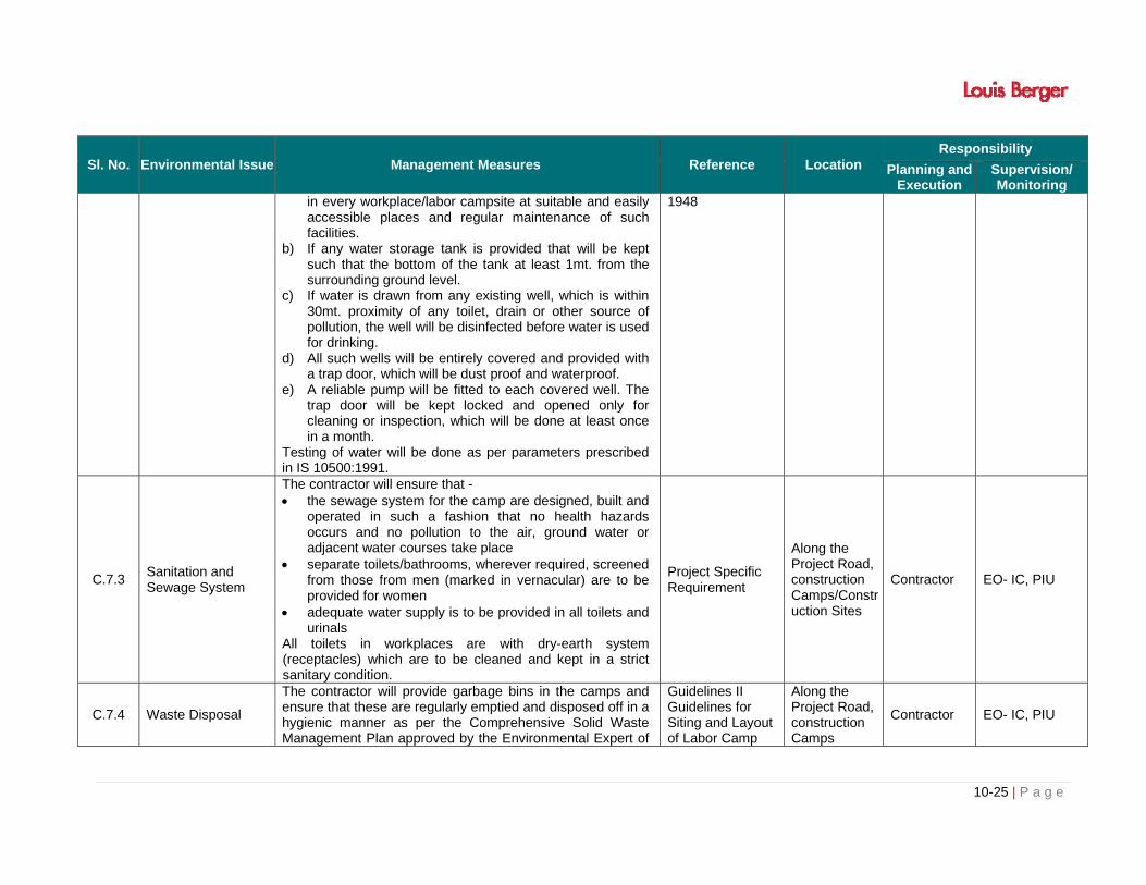
10-25 | P a g e
Sl. No. Environmental Issue Management Measures Reference Location Responsibility
Planning and Execution
Supervision/ Monitoring
in every workplace/labor campsite at suitable and easily accessible places and regular maintenance of such facilities.
b) If any water storage tank is provided that will be kept such that the bottom of the tank at least 1mt. from the surrounding ground level.
c) If water is drawn from any existing well, which is within 30mt. proximity of any toilet, drain or other source of pollution, the well will be disinfected before water is used for drinking.
d) All such wells will be entirely covered and provided with a trap door, which will be dust proof and waterproof.
e) A reliable pump will be fitted to each covered well. The trap door will be kept locked and opened only for cleaning or inspection, which will be done at least once in a month.
Testing of water will be done as per parameters prescribed in IS 10500:1991.
1948
C.7.3 Sanitation and Sewage System
The contractor will ensure that - the sewage system for the camp are designed, built and
operated in such a fashion that no health hazards occurs and no pollution to the air, ground water or adjacent water courses take place
separate toilets/bathrooms, wherever required, screened from those from men (marked in vernacular) are to be provided for women
adequate water supply is to be provided in all toilets and urinals
All toilets in workplaces are with dry-earth system (receptacles) which are to be cleaned and kept in a strict sanitary condition.
Project Specific Requirement
Along the Project Road, construction Camps/Construction Sites
Contractor EO- IC, PIU
C.7.4 Waste Disposal
The contractor will provide garbage bins in the camps and ensure that these are regularly emptied and disposed off in a hygienic manner as per the Comprehensive Solid Waste Management Plan approved by the Environmental Expert of
Guidelines II Guidelines for Siting and Layout of Labor Camp
Along the Project Road, construction Camps
Contractor EO- IC, PIU

10-26 | P a g e
Sl. No. Environmental Issue Management Measures Reference Location Responsibility
Planning and Execution
Supervision/ Monitoring
IC. Unless otherwise arranged by local sanitary authority, arrangements for disposal of night soils (human excreta) suitably approved by the local medical health or municipal authorities or as directed by Environmental Expert of IC will have to be provided by the contractor.
C.8
C.8.1 Accessibility
The ‘EO-IC’ will contact the responsible people with the enhancement drawing of the site for which enhancement has been proposed and take their consent before the start of work. Accesses to Different Schools along the road will be developed to the satisfaction of ‘PIU’.
Along the Project Road
Contractor EO- IC, PIU
C.9
C.9.1
Clean-up Operations, Restoration and Rehabilitation
Contractor will prepare site restoration plans, which will be approved by the Environmental Expert of IC. The clean-up and restoration operations are to be implemented by the contractor prior to demobilization. The contractor will clear all temporary structures; dispose all garbage, night soils and POL waste as per Comprehensive Waste Management Plan and as approved by IC. All disposal pits or trenches will be filled in and effectively sealed off. Residual topsoil, if any will be distributed in pre identified approved areas or in places suggested by the ‘EO - IC’ areas in a layer of thickness of 75 mm-l50 mm. All construction zones including river-beds, culverts, road-side areas, camps, hot mix plant sites, crushers, batching plant sites and any other area used/affected by the project will be left clean and tidy, at the contractor's expense, to the entire satisfaction to the Environmental Expert of IC and PIU/ MMRDA will certify in this regard.
Guidelines IV Guidelines for Disposal Site management
Along the Project Road, construction Camps
Contractor EO- IC, PIU

10-27 | P a g e
Table 10.2: Environmental Management Plan for Operation Phase
Sl. No. Environmental Issue Management Measures Reference Time Frame
Location Responsibility
Execution/ Civil Work
Supervision/Monitoring
OPERATION STAGE
Activities to be Carried Out by the PIU
O.1 Monitoring Operation Performance
The PIU will monitor the operational performance of the various mitigation/ enhancement measures carried out as a part of the project. The indicators selected for monitoring include the survival rate of trees; utility of enhancement provision, status of rehabilitation of borrow areas and disposal sites,
Operation
Phage Along the
Project RoadPIU PIU
O.2 Maintenance of Drainage
PIU will ensure that all drains (side drains, median drain and all cross drainages) are periodically cleared especially before monsoon season to facilitate the quick passage of rainwater and avoid flooding. PIU will ensure that all the sediment and oil and grease traps set up at the water bodies are cleared once in every three months.
Operation
Phase Along the
Project RoadPIU PIU
O.3 Pollution Monitoring
The periodic monitoring of the ambient air quality, noise level, water (both ground and surface water) quality, soil pollution/contamination in the selected locations as suggested in pollution monitoring plan or as recommended by IC-EO (Refer Chapter 3 for Monitoring Locations of air, water and noise ) will be responsibility of PIU. PIU will either appoint PCB or its approved pollution-monitoring agency for the purpose
Operation
Phase Along the
Project Road
PIU through Pollution Monitoring Agency
PIU
O.3.1 Atmospheric Pollution Ambient air concentrations of various pollutants shall be monitored as envisaged in the pollution-monitoring plan
Air (P & CP) Act 1981
Operation Phase
Along the Project Road
PIU through Pollution Monitoring Agency
PIU
O.3.2 Noise Pollution
Noise pollution will be monitored as per monitoring plan at sensitive locations. Noise control programs are to be enforced strictly. Monitoring the effectiveness of the pollution attenuation
Noise Rules 2002
Operation Phase
Along the Project Road
PIU through Pollution
Monitoring
PIU

10-28 | P a g e
Sl. No. Environmental Issue Management Measures Reference Time Frame
Location Responsibility
Execution/ Civil Work
Supervision/Monitoring
barriers Hospital Boundary wall will be taken up thrice in the operation period.
Agency
O.3.3 Water Pollution Water Quality will be monitored as per monitoring plan Water (P & CP) Act 1974
Operation Phase
Along the Project Road
PIU through Pollution
Monitoring Agency
PIU
O.4. Soil Erosion and
Monitoring of Borrow Areas
Visual monitoring and inspection of soil erosion at borrow areas, quarries (if closed and rehabilitated), and embankment > 2m and other places expected to be affected, will be carried out once in every three months as suggested in monitoring plan.
IRC/Environmental Conservation Act
Operation Phase
Along the Project Road
PIU PIU
O.5 Road Safety Road Safety will be monitored during operation especially at location where traffic-calming measures have been proposed.
IRC Guidelines Operation
Phase Along the
Project RoadPIU PIU


i | P a g e
TABLE OF CONTENTS
CHAPTER - 11: SUMMARY AND CONCLUSION .............................................................................. 11-1
11.1 PROJECT BACKGROUND AND DESCRIPTION ............................................................ 11-1
11.2 ENVIRONMENTAL ASSESSMENT OF THE PROJECT .................................................. 11-3
11.3 ANTICIPATED ENVIRONMEMNTAL IMPACTS AND MITIGATION MEASURES ........... 11-4
11.4 ANALYSIS OF ALTERNATIVES ...................................................................................... 11-5
11.5 ENVIRONMENTAL MONITORING PROGRAMME .......................................................... 11-8
11.6 ADDITIONAL STUDIES ................................................................................................... 11-8
11.7 PROJECT BENEFITS ...................................................................................................... 11-9
11.8 MITIGATION AND ENHANCEMENT MEASURES .......................................................... 11-9
11.9 INSTITUTIONAL ARRANGEMENTS ............................................................................. 11-14
11.10 CONCLUSIONS ............................................................................................................. 11-14
LIST OF TABLES
Table 11.1: Baseline Environmental Scenario in the Project Area ........................................................ 11-3
Table 11.2: Environmental Impact Summary ........................................................................................ 11-4
Table 11.3: “With” and “Without” Project Scenarios. ............................................................................. 11-5
Table 11.4: Key Environmental Impacts and Management/ Mitigation Measures ............................... 11-10
Table 11.5: Summary of Environment Budget* ................................................................................... 11-14


11-1 | P a g e
CHAPTER - 11: SUMMARY AND CONCLUSION
11.1 PROJECT BACKGROUND AND DESCRIPTION
The purpose of this chapter is to introduce the scope and objective of the project works in
general and EIA and EMP in particular within which the detailed Environmental Assessment
studies of Multi Modal corridors have been carried out. This chapter also discusses the nature,
size, location of the project along with brief structure of the EIA reports.
Multi Modal corridor has been planned to cater need of growing population along fringe areas.
Other objective of the project is to provide connectivity to industrial and commercial
establishment in SEZ area to residential areas of satellite towns of Mumbai Metropolitan region
with diverse mode of transport. The proposed MMC alignment is take off from km 490.075 of
NH-8 near Navgarh and ends it open agriculture land near Chirner village (near JNPT). The
Project alignment is traversing through Palghar, Thane and Raigad District in the State of
Maharashtra. The Total Length of the Project Mumbai Multi Modal Corridor is approx. 80 Km
Project Description
A Multi Modal Corridor is a single corridor in which multiple modes, such as buses, BRT, metro
rail and cars, along with utilities such as water, sewage and gas lines are present in the same
Right of Way. The Right of way (ROW) of Proposed Multi Modal Corridor is 99 meters.
The MMC was envisaged to provide connectivity to existing and future growth centers in the
MMR. The MMC will help the growth of 7 Growth centers viz. Virar, Bhiwandi, Kalyan, Dombivali,
Panvel, Uran and Taloja MIDC in the MMR Region. It would provide faster connectivity between
the Urban Local Bodies (ULBs) located outside Greater Mumbai and improve accessibility to
inter-city freight traffic.
The MMC will connect the major roads such as NH-8, Bhiwandi bypass, NH-3, NH-4, NH-4B,
Mumbai Pune Expressway, NH-17 etc. The Corridor will provide faster connectivity to JNPT,
Proposed Navi Mumbai Airport, MTHL Project and Dedicated Freight Corridor (DFC).
The Project area traverses through the plain and rolling terrain and passes through Palghar,
Thane and Raigad district of Maharashtra. The Corridor is running parallel to Bassien Creek up
to Ulhas River (near Kalher).
The Project alignment is traversing through Palghar, Thane and Raigad Districts in the State of
Maharashtra. The total length of the Project Mumbai Multi Modal Corridor is approx. 80 Km. The
entire length of the project alignment is divided into 6 sections are as follows:
The Section 1-2 of the MMC alignment (approx. 13 Km) starts from the junction of NH8
(Navghar) and the Diva Vasai Rail line and runs parallel to Diva Vasai Rail Line / Kaman village
and ends near Kharbav Railway Station/Dunge Village.
The Section 2-3 of the MMC alignment (approx. 5 Km) starts near Kharbav Railway
Station/Dunge Village and ends near Kalher Reti Bunder passing through Dive Village Gavthan.

11-2 | P a g e
The Section 3-4 of the MMC alignment (approx. 16 Km) starts near Kalher Reti Bunder and ends
at Shidhon Village near Hedutane Gaon passing through Alimghar Village, Ulhas River, west of
Sandap Gaon and Kolegaon.
The Section 4-5 of the MMC alignment (approx. 25 Km) starts at Shidhon Village near Hedutane
Gaon and ends near Kolkhe Village (near Panvel /Mumbai Pune Express Highway) passing
through Utasane Village, Mahulangi Village and Wangani Village.
The Section 5-6 of the MMC alignment (approx. 20Km) runs from Kolkhe Village (near Panvel /
Mumbai Pune Express Highway) and ends at Chirner near JNPT running parallel to NH 4 B
passing through Nandgaon and Chirle Goan.
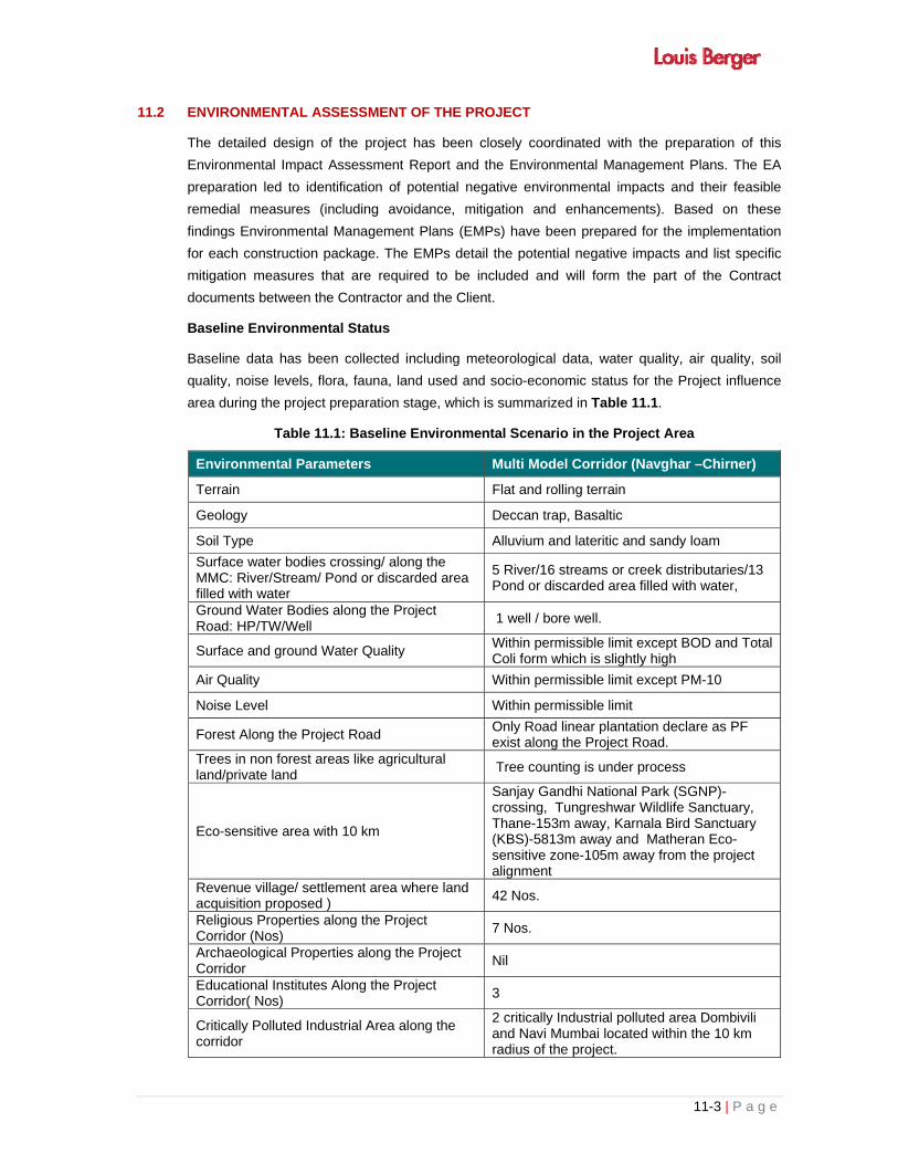
11-3 | P a g e
11.2 ENVIRONMENTAL ASSESSMENT OF THE PROJECT
The detailed design of the project has been closely coordinated with the preparation of this
Environmental Impact Assessment Report and the Environmental Management Plans. The EA
preparation led to identification of potential negative environmental impacts and their feasible
remedial measures (including avoidance, mitigation and enhancements). Based on these
findings Environmental Management Plans (EMPs) have been prepared for the implementation
for each construction package. The EMPs detail the potential negative impacts and list specific
mitigation measures that are required to be included and will form the part of the Contract
documents between the Contractor and the Client.
Baseline Environmental Status
Baseline data has been collected including meteorological data, water quality, air quality, soil
quality, noise levels, flora, fauna, land used and socio-economic status for the Project influence
area during the project preparation stage, which is summarized in Table 11.1.
Table 11.1: Baseline Environmental Scenario in the Project Area
Environmental Parameters Multi Model Corridor (Navghar –Chirner)
Terrain Flat and rolling terrain
Geology Deccan trap, Basaltic
Soil Type Alluvium and lateritic and sandy loam
Surface water bodies crossing/ along the MMC: River/Stream/ Pond or discarded area filled with water
5 River/16 streams or creek distributaries/13 Pond or discarded area filled with water,
Ground Water Bodies along the Project Road: HP/TW/Well
1 well / bore well.
Surface and ground Water Quality Within permissible limit except BOD and Total Coli form which is slightly high
Air Quality Within permissible limit except PM-10
Noise Level Within permissible limit
Forest Along the Project Road Only Road linear plantation declare as PF exist along the Project Road.
Trees in non forest areas like agricultural land/private land
Tree counting is under process
Eco-sensitive area with 10 km
Sanjay Gandhi National Park (SGNP)- crossing, Tungreshwar Wildlife Sanctuary, Thane-153m away, Karnala Bird Sanctuary (KBS)-5813m away and Matheran Eco-sensitive zone-105m away from the project alignment
Revenue village/ settlement area where land acquisition proposed )
42 Nos.
Religious Properties along the Project Corridor (Nos)
7 Nos.
Archaeological Properties along the Project Corridor
Nil
Educational Institutes Along the Project Corridor( Nos)
3
Critically Polluted Industrial Area along the corridor
2 critically Industrial polluted area Dombivili and Navi Mumbai located within the 10 km radius of the project.

11-4 | P a g e
Environmental Parameters Multi Model Corridor (Navghar –Chirner)
Land Use Along the road Agriculture, Built up Area, residential and river, creeks, road, railways, mangroves and CRZ areas
Diversion of land for proposed MMC 14.8ha National Park land, 69.2743ha Mangroves area, Non Forest= 725 hectares
11.3 ANTICIPATED ENVIRONMEMNTAL IMPACTS AND MITIGATION MEASURES
Key Environmental Issues along the Project Road:
Surface Water Pollution
Impact on Religious Properties
Felling of trees along the project road as well as in agriculture areas
Diversion of Forest land declare
Diversion of Mangroves land
Diversion of forest land
Loss of agriculture land
Road Safety
The assessment of impacts on various environmental components from the project roads is
summarized in Table 11.2:
Table 11.2: Environmental Impact Summary
Sl. No. Parameter Details
Negative Impacts
1 Wells (Nos.) 1 Well
2 Diversion of Agricultural land (ha.) 725 hectares
3 Diversion of Forest Land Under progress
4
Diversion of CRZ-I area (ha.) CRZ IA (RF) Other CRZ(III & IVB)
69.2743ha
12.5297ha 122.1294ha
5 Borrow Earth (Cum) Require d in large amount
6 Quarry Material (Cum) Required in large amount
7 Water (Kl) Required in large amount during construction
9 Nos of trees to be felled (Nos) in non forest + forest
Tree counting under process
10 Surface water body 5 River/18 streams or creek distributaries/12 Pond or discarded area filled with water,

11-5 | P a g e
Sl. No. Parameter Details
11 Cultural/Religious Properties 3 nos.
Positive Impacts
1 Enhancement sites Through compensatory afforestation in degraded forest area/ revenue area and avenue plantation along the corridor
2 Median Plantation Provided (1500 plants / km ) i.e 450000 Shrubs
3 Connectivity and road safety Improved
4 Safe Assess to Educational Institute
Improved
5 Enhancement of Service road Improved
6 Junctions/Interchange All junction/ Interchange will be improve through provision of under passes
7 Sitting Arrangement improved
Road safety Measures
1 Interchange At 10 location interchange
2 Street lighting (locations) Provided\ Improved all along the major bridges and flyovers /elevated sections
3 Signage Improved all along the project road
4 Intersection Signs Provided
5 Sign on Side roads provided
6 School Signs provided
7 Place identification Sign Provided
8 Traffic calming measures (locations)
provided
9 Drainage provided
10 Crash Barriers / Guardrails Provided where as it required
11 Silence Zone Signs Provided
12 Industrial establishment Signs Provided
Mitigation measures are provided in the Table 11.4.
11.4 ANALYSIS OF ALTERNATIVES
Analysis for alternatives was carried out for different parameters as given below:
Table 11.3: “With” and “Without” Project Scenarios.
Sl. No.
Scenario type Long-Term Scenario “With” Project Long-Term Scenario
“Without” Project
Environment
A. Physical Environment
i) Atmosphere and Climate
Travel time and traffic congestion will reduce as a result of 4-laning of the project road. Overall, a lower or similar level of air pollution. No change in climatic condition
Congested road will consume more travel time and will increase air pollution. No change in climatic condition
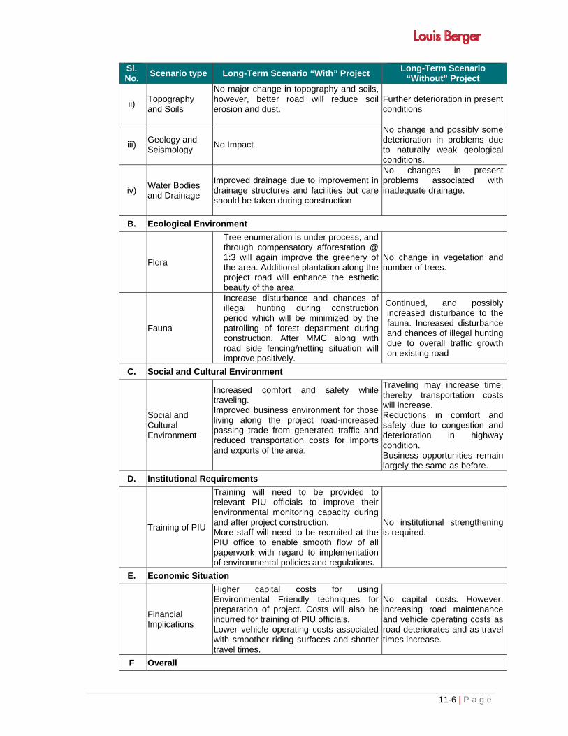
11-6 | P a g e
Sl. No.
Scenario type Long-Term Scenario “With” Project Long-Term Scenario
“Without” Project
ii) Topography and Soils
No major change in topography and soils, however, better road will reduce soil erosion and dust.
Further deterioration in present conditions
iii) Geology and Seismology
No Impact
No change and possibly some deterioration in problems due to naturally weak geological conditions.
iv) Water Bodies and Drainage
Improved drainage due to improvement in drainage structures and facilities but care should be taken during construction
No changes in present problems associated with inadequate drainage.
B. Ecological Environment
Flora
Tree enumeration is under process, and through compensatory afforestation @ 1:3 will again improve the greenery of the area. Additional plantation along the project road will enhance the esthetic beauty of the area
No change in vegetation and number of trees.
Fauna
Increase disturbance and chances of illegal hunting during construction period which will be minimized by the patrolling of forest department during construction. After MMC along with road side fencing/netting situation will improve positively.
Continued, and possibly increased disturbance to the fauna. Increased disturbance and chances of illegal hunting due to overall traffic growth on existing road
C. Social and Cultural Environment
Social and Cultural Environment
Increased comfort and safety while traveling. Improved business environment for those living along the project road-increased passing trade from generated traffic and reduced transportation costs for imports and exports of the area.
Traveling may increase time, thereby transportation costs will increase. Reductions in comfort and safety due to congestion and deterioration in highway condition. Business opportunities remain largely the same as before.
D. Institutional Requirements
Training of PIU
Training will need to be provided to relevant PIU officials to improve their environmental monitoring capacity during and after project construction. More staff will need to be recruited at the PIU office to enable smooth flow of all paperwork with regard to implementation of environmental policies and regulations.
No institutional strengthening is required.
E. Economic Situation
Financial Implications
Higher capital costs for using Environmental Friendly techniques for preparation of project. Costs will also be incurred for training of PIU officials. Lower vehicle operating costs associated with smoother riding surfaces and shorter travel times.
No capital costs. However, increasing road maintenance and vehicle operating costs as road deteriorates and as travel times increase.
F Overall

11-7 | P a g e
Sl. No.
Scenario type Long-Term Scenario “With” Project Long-Term Scenario
“Without” Project
Long term improved social and environmental conditions but an increase in expenses for project activities during the course of project construction and it will slightly effect the forest area during construction period
Small deteriorations in environmental conditions, no increase in economic opportunities and increased expenses associated with maintenance.
11-8 | P a g e
The project should lead to an overall improvement in environmental and social conditions
through the landscaping. It is, nevertheless important to use environmentally friendly road
construction techniques.
11.5 ENVIRONMENTAL MONITORING PROGRAMME
To ensure the effective implementation of the EMP, it is essential that an effective monitoring
program be designed and carried out. The environmental monitoring programme provides such
information based on which management decision may be taken during construction and
operational phases. It provides basis for evaluating the efficiency of mitigation and enhancement
measures and suggest further actions that need to be taken to achieve the desired effect.
The monitoring includes:
Visual observations;
Selection of environmental parameters at specific locations;
To know the effective implementation of the EMP, air, water and noise levels will be monitored
during construction and operation phase of the project, details are described in chapter 6.
11.6 ADDITIONAL STUDIES
PUBLIC CONSULTATIONS
Discussions were held with most of the stakeholders with different type of consultations such as
formal, informal and group discussions. The following issued have been discussed during public
consultation which will be suitability incorporated in EMP
Parking facilities
Dust suppression measures should be adopted
Sign boards for road safety
Provision of service road
Employment opportunity to local people during 4-laning of project road
Junction improvement
Drainage management
Suitable compensation
Plantation of trees along the project road
Plantation of plant in median
Air, and Noise management during construction
CONTINUED PARTICIPATION MECHANISM
Two stages consultation was carried out in Project Corridor. In first stage consultation
Information about the project was disseminated to the local people and their views/Grievances/
Suggestions were solicited. These suggestions were incorporated into the design to the extent
possible and Second round of consultation was carried out with a objective to inform the people

11-9 | P a g e
about the design, suggestions which could be addressed and reasons for non incorporation of
their suggestion thereof and communities were shown enhancement drawings and briefed about
the enhancement measures and this process will continue through out the construction period.
11.7 PROJECT BENEFITS
Positive and negative aspects of the project have been discussed detailed in following paragraph. Key long-term environmental and social benefits from the project will arise mainly from traditional sources
savings in travel times, reduce the emission of dust;
reduced cargo delays – from faster vehicle speeds and reductions in travel time;
reduced vehicle operating costs – from improved riding surfaces;
reduced road maintenance costs – from higher quality infrastructure;
reduced accidents – mainly as a result of reduced travel time and congestion but also because of the provision of safety infrastructure and warning signs, though this latter
element was impossible to quantify – it was, however, estimated that the benefits from a 50% reduction in accidents; and
A large volume of generated traffic is, however, also forecast. This is traffic stimulated by the
reduction in travel costs and associated with new economic development. The benefits calculated subsume the benefits from:
improved access to the Navaghar to Chirner (JNPT)
new businesses, including that from increased passing trade
The key negative, permanent and irreversible impacts will occur along the realignment and will
be:
loss of hectares of forest land;
loss of mangroves area
loss of trees in forest and non-forest area
loss of agriculture land
a marginal reduction in aesthetic beauty
All the trees felled due to this project will be compensated to reduce the negative impact of the
area
11.8 MITIGATION AND ENHANCEMENT MEASURES
As far as possible avoidance and reduction of adverse impacts approaches were adopted during
the design stage with consideration of the views of local communities and the design team
including engineers, environmental and social experts. This is reflected in the finalization of the
cross sections, construction methods, construction materials and alignment.
Compensatory and additional plantation along with landscaping will be carried to improve the
esthetic value of the areas in future. All identified impact will be either suitably mitigated or
compensated, so that development will become eco-Friendly. A summary of mitigation measures
proposed to mitigate the adverse impacts are presented in Table 11.4:

11-10 | P a g e
Table 11.4: Key Environmental Impacts and Management/ Mitigation Measures
Area Impacts Management/Mitigation Measures
Construction Phase
Topography & geology
• Disfiguration & change in existing profile of the land due to borrow pits & construction of new bypass.
• Disturbance on geological setting due to quarrying.
• Uncontrolled digging of borrow pits resulting in water accumulation & breeding of vector disease.
• Borrow pits will be restricted to 1 m depth followed by resurfacing of pits. • Road building materials will be procured from approved and licensed quarries
only. • Suitable seismic design of the bridge structures will be adopted to mitigate the
earthquake impacts.
Soil
• Disruption & loss of productive top soil from agricultural fields due to borrow pits which may reduce crop yield.
• Loosening of top soil & loss of vegetative cover along the road due to excavation & back filling which will lead to enhanced soil erosion.
• Adequate measures like adequate drainage, embankment consolidation & slope stabilization will be taken along the road to avoid soil erosion.
• Top soils (15 cm) of borrow pit sites will be conserved and restored after excavation is over.
• Accidental spillage of lubricants/oil and molten asphalt will be avoided by adherence to good practices.
Land use
• Loss of agricultural land resources due to land acquisition for the road.
• Generation of solid waste in the form of construction spoils from construction sites.
• Changes in existing land use pattern of the ROW for construction of the road.
• Loss of trees and diversion of forest land • Generation of bituminous waste due to scarifying
of damaged pavement
• Earth material generated from excavation of roadways & drainage will be reused during site development.
• Construction debris will be disposed of in suitable pre-identified dumping areas. • Dumping areas will be biologically reclaimed. • Construction camp will be provided to avoid indiscriminate settlement of
construction workers. • Compensatory and additional plantation will be carried out along the road • Staging of the debris on / along the road will not be allowed. Regular inspection
of construction site will be carried out to ensure for this. • Scarified bitumen will be recycled for use below Sub grade under pavement or
below GSB under shoulder.
Drainage
• Change in drainage pattern of the land. • Increased incidence and duration of floods due to
obstruction of natural drainage courses by the road embankment.
• Chances of filling of existing drainage courses during earth filling.
• Adequate lined and covered drains are provided for the project to facilitate its long life, and to avoid soil erosion & land degradation.
• Adequate cross drainage works & structures will be provided for smooth passage of runoff to avoid flooding.
• Steps at the bridge sites will be provided to inspect, regular cleaning and inspection of these sites.
• Filling of existing drainage courses will be strictly avoided. • Suitable drainage at construction site & camp will be provided to avoid water
stagnation, soil erosion & mosquito breeding.

11-11 | P a g e
Area Impacts Management/Mitigation Measures
Water bodies • Loss of water resources due to complete or partial
filling up of few ponds/water bodies along the road. • Filling of water bodies along the road alignment will be minimized by providing
retaining walls.
Water use • Impact on the local water sources due to use of
construction water. • Minimum use of existing water sources for construction will be ensured to
minimize likely impacts on other users.
Water quality
• Increase of sediment load in the run off from construction sites and increase in turbidity in receiving streams/water bodies.
• Water pollution due to sewage from construction camps.
• Sediment traps will be provided to reduce sediment load in construction wastewater.
• Proper sanitation facilities will be provided in construction camp to prevent health related problems.
• All the construction activities will be carried out during dry seasons only.
Air quality
• Deterioration of air quality due to fugitive dusts emission from construction activities like excavation, backfilling & concreting, and hauling & dumping of earth materials & construction spoils, and vehicular movement along unpaved roads.
• Deterioration of air quality due to gaseous emissions from construction equipment & vehicular traffic.
• Deterioration of air quality due to emission from asphalt and hot mix plants.
• Construction materials will be stored in enclosed spaces to prevent fugitive emissions.
• Truck carrying soil, sand and stone will be duly covered to avoid spilling. • Adequate dust suppression measures such as regular water sprinkling on haul &
unpaved roads particularly near habitation will be undertaken to control fugitive dust.
• Stringent construction material handling/overhauling procedures will be followed. • Low emission construction equipment & vehicles will be used. • It will be ensured that all construction equipment & vehicles are in good working
condition, properly tuned & maintained to keep emissions within permissible limits.• Asphalt and hot mix plants will be located at least 500 m away from inhabited
areas and 300 m from the road.
Noise level • Increase in noise level due to construction activities
like operation of construction equipment & vehicular traffic.
• Construction camp and temporary labour sheds will be located away from the immediate vicinity of the construction sites and major road traffic.
• Protective gears such as ear plugs etc. will be provided to construction personnel exposed to high noise levels as preventive measure.
• Low noise construction equipment will be used. • It will be ensured that all construction equipment & vehicles are in good working
condition, properly lubricated & maintained to keep noise within permissible limits. • Stationary construction equipment will be placed sufficiently away from inhabited
areas and silence zones. • Construction activities carried out near residential area will be scheduled to the
day time only so that minimum disturbances are caused to people.
Floral & fauna • Loss of flora & loss of habitat of avian fauna due to
felling of trees along the ROW. • Short term disturbance to avian fauna.
• No tree shall be felled beyond the toe line of proposed cross section. • Two times of area of diverted forest land will be afforested as per direction of
forest department. PIU will deposit the required amount for afforested as forest department will specify for compensatory plantation. In addition to this Net
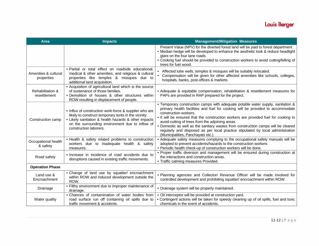
11-12 | P a g e
Area Impacts Management/Mitigation Measures
Present Value (NPV) for the diverted forest land will be paid to forest department • Median hedge will be developed to enhance the aesthetic look & reduce headlight
glare on the four lane roads. • Cooking fuel should be provided to construction workers to avoid cutting/felling of
trees for fuel wood.
Amenities & cultural properties
• Partial or total effect on roadside educational, medical & other amenities, and religious & cultural properties like temples & mosques due to additional land acquisition.
• Affected tube wells, temples & mosques will be suitably relocated. • Compensation will be given for other affected amenities like schools, colleges,
hospitals, banks, post-offices & markets.
Rehabilitation & resettlement
• Acquisition of agricultural land which is the source of sustenance of those families.
• Demolition of houses & other structures within ROW resulting in displacement of people.
• Adequate & equitable compensation, rehabilitation & resettlement measures for PAPs are provided in RAP prepared for the project.
Construction camp
• Influx of construction work-force & supplier who are likely to construct temporary tents in the vicinity.
• Likely sanitation & health hazards & other impacts on the surrounding environment due to inflow of construction laborers.
• Temporary construction camps with adequate potable water supply, sanitation & primary health facilities and fuel for cooking will be provided to accommodate construction workers.
• It will be ensured that the construction workers are provided fuel for cooking to avoid cutting of trees from the adjoining areas.
• Domestic as well as the sanitary wastes from construction camps will be cleared regularly and disposed as per local practice stipulated by local administration (Municipalities, Panchayats etc.).
Occupational health & safety
• Health & safety related problems to construction workers due to inadequate health & safety measures.
• Adequate safety measures complying to the occupational safety manuals will be adopted to prevent accidents/hazards to the construction workers
• Periodic health check-up of construction workers will be done.
Road safety • Increase in incidence of road accidents due to
disruptions caused in existing traffic movements.
• Proper traffic diversion and management will be ensured during construction at the interactions and construction areas.
• Traffic calming measures Provided.
Operation Phase
Land use & Encroachment
• Change of land use by squatter/ encroachment within ROW and induced development outside the ROW.
• Planning agencies and Collector/ Revenue Officer will be made involved for controlled development and prohibiting squatter/ encroachment within ROW.
Drainage • Filthy environment due to improper maintenance of
drainage. • Drainage system will be properly maintained.
Water quality • Chances of contamination of water bodies from
road surface run off containing oil spills due to traffic movement & accidents.
• Oil interceptor will be provided at construction yard. • Contingent actions will be taken for speedy cleaning up of oil spills, fuel and toxic
chemicals in the event of accidents.

11-13 | P a g e
Area Impacts Management/Mitigation Measures
Air quality • Air pollution due to vehicular emission from road
traffic.
• Vehicular emission will be controlled through enforcement of laws and public awareness.
• Truck parking lay-byes and bus bays will be provided at required locations to facilitate smooth traffic flow.
• Regular monitoring of air quality at specified locations will be conducted.
Noise level • Noise pollution due to trafic noise.
• Vehicular noise & use of horns will be controlled through enforcement of laws and public awareness.
• Road signs prohibiting the use of horns will be placed at residential areas, sensitive locations & silence zones.
• Regular monitoring of noise level at specified locations will be conducted by PIU.
Flora & fauna • Illegal felling of road side plantation. • Effect on aquatic fauna in case of accidental spill of
oil, fuel & toxic chemicals into water bodies.
• Plantation along the ROW will be maintained properly and protected from illegal felling.
• Contingent actions will be taken in the event accidental spill of oil, fuel & toxic chemicals.
Access • Significant severance problem on pedestrian &
cattle crossing and cross traffic due to widening, partially access control & increase in traffic speed.
• Intersection & approach of existing major cross roads will be upgraded. • Cattle/animal crossings to facilitate smooth traffic & pedestrian movement to avoid
accidents. • Access of primary schools will be modified in S shaped to slow down the speed of
the primary school children, when they come out. It will avoid chances for accidents of school children.
• Bus bays will be provided at suggested suitable locations.
Road safety • Impacts on human health due to accidents. • Damage of road due to wear & tear.
• Adequate traffic safety measures e.g. crash barriers & pedestrian railings will be provided wherever required.
• Proper & adequate road signs, road markings, kerb paintings and road furniture like overhead gantry signs, roadway delineators etc. will be provided.
• Adequate illumination will be provided at interchange locations for safe and efficient traffic operations especially during night and inclement weather.
• Periodical inspection of the road will be conducted to detect anomalies in pavement.
• Emergency telephone communication system, highway patrolling, crane and ambulance facilities will be provided.
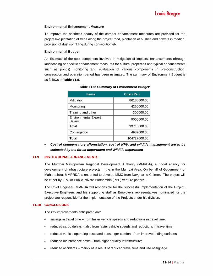
11-14 | P a g e
Environmental Enhancement Measure
To improve the aesthetic beauty of the corridor enhancement measures are provided for the
project like plantation of trees along the project road, plantation of bushes and flowers in median,
provision of dust sprinkling during consecution etc.
Environmental Budget
An Estimate of the cost component involved in mitigation of impacts, enhancements (through
landscaping or specific enhancement measures for cultural properties and typical enhancements
such as ponds) monitoring and evaluation of various components in pre-construction,
construction and operation period has been estimated. The summary of Environment Budget is
as follows in Table 11.5.
Table 11.5: Summary of Environment Budget*
Items Cost (Rs.)
Mitigation 86180000.00
Monitoring 4260000.00
Training and other 300000.00
Environmental Expert Salary
9000000.00
Total 99740000.00
Contingency 4987000.00
Total 104727000.00
Cost of compensatory afforestation, cost of NPV, and wildlife management are to be
estimated by the forest department and Wildlife department
11.9 INSTITUTIONAL ARRANGEMENTS
The Mumbai Metropolitan Regional Development Authority (MMRDA), a nodal agency for
development of infrastructure projects in the in the Mumbai Area. On behalf of Government of
Maharashtra, MMRRDA is entrusted to develop MMC from Navghar to Chirner. The project will
be either by EPC or Public Private Partnership (PPP) venture pattern.
The Chief Engineer, MMRDA will responsible for the successful implementation of the Project.
Executive Engineers and his supporting staff as Employers representatives nominated for the
project are responsible for the implementation of the Projects under his division.
11.10 CONCLUSIONS
The key improvements anticipated are:
savings in travel time – from faster vehicle speeds and reductions in travel time;
reduced cargo delays – also from faster vehicle speeds and reductions in travel time;
reduced vehicle operating costs and passenger comfort– from improved riding surfaces;
reduced maintenance costs – from higher quality infrastructure;
reduced accidents – mainly as a result of reduced travel time and use of signage

11-15 | P a g e
A large volume of generated traffic is forecasted. This will be traffic stimulated by the
reduction in travel costs and associated with new economic development and deriving,
amongst other things, from:
New businesses, including those from increased passing trade.
In addition to the above, there should be:
an overall reduction in problems from exhaust emission improved drainage; and
A wide range of short-term negative impacts are, however, envisaged during construction - these
include: disturbance to wildlife and settlements; localised dust pollution; increased sediments in
water bodies; small-scale erosion; and health hazards amongst construction workers and those
residing in nearby settlements. However, most of these can be adequately mitigated through:
practicing Environmental Friendly Road Construction techniques; proper location of construction
camps; and equipping construction sites with adequate medical facilities.
The major long-term negative impact will be the permanent loss of about 14.8ha land of Sanjay
Gandhi national Park, and 793 ha non forest land tree located within the proposed ROW of MMC
will be removed. This can, however, be mitigated by plantation under compensatory
afforestation. There may also be some small-scale temporary impacts on wildlife habitats.
However, investigations show that this is not a significant issue for important protected species.
Removal of only necessary vegetation during construction, and thereafter the maintenance of
forest cover on both sides of the project road, will help minimise long-term negative impacts.


12-i | P a g e
TABLE OF CONTENTS
CHAPTER - 12: DISCLOSURE OF CONSULTANTS ENGAGED ....................................................... 12-1
12.1 DISCLOSURE OF CONSULTANTS ........................................................................................ 12-1
12.2 DISCLOSURE OF PROJECT AND EIA/EMP REPORT .......................................................... 12-1
12.2.1 Approved Key Professional from QCI ......................................................................... 12-1


12-1 | P a g e
CHAPTER - 12: DISCLOSURE OF CONSULTANTS ENGAGED
12.1 DISCLOSURE OF CONSULTANTS
Messrs Louis Berger Consulting Pvt. Ltd, have been entrusted with the Consultancy services for
obtaining environmental clearance from the Ministry of Environment, Forests and Climate
Change (MoEF&CC) , Government of India.
In order to full fill the above task, MMRDA has appointed M/s Louis Berger Consulting, Pvt. Ltd.
as Consultants to carry out the above tasks and Contract agreement was signed on 16 July 2014
LBG is one of the largest multi-disciplinary consulting organizations in the world, being amongst
the leaders in the transportation (urban roads, highways, expressways, bridges etc.), urban
infrastructure development (water supply, sewerage, solid waste management, etc.) and
environmental engineering sectors (as per rankings of the Engineering News Record published
by McGraw Hill). With over 55 years of experience worldwide including about 50 years in South
Asia, the Berger Group can draw upon the experience, versatility and innovativeness of over
5,000 professional staff members in all facets of planning, design, design vetting, supervision,
project management, monitoring, evaluation, technical assistance, operation and maintenance,
independent engineering, impact assessment and management of multi-faceted and complex
projects worldwide.
12.2 DISCLOSURE OF PROJECT AND EIA/EMP REPORT
In order to enable timely project implementation, continued dialogue and coordination will need to
take place between the Client, Consultant and relevant agencies.
Intimation on the availability of the report to the public will be made through mass media. The
English version of the document will be available in the offices of MMRAD PCB/Concerned
Collectors.
This EIA report will also be made available on the websites of the MMRAD/MOEF&CC.
12.2.1 Approved Key Professional from QCI
Sl. No.
Name of the Expert
Position Responsibility Signature
1 Dr. D K Pandey
EIA Coordinator (Category 7(f), 8(b) Highways, Railways, transport terminals, mass rapid transport system)
Preparation of EIA and EMP, liaising with MOEF/J&K PCB/Forest Dept., monitoring of data etc.
2
Dr. D K Pandey Functional Area Expert- Ecology & Biodiversity
Study of the ecological profile of the project area.
3 Dr. D K Pandey Functional Area Expert- Noise & Vibration
Study of Noise of the project area
4 Mr. Anil Sharma Functional Area Expert- Socio-
Study of socio-economic profile of the area, impact of

12-2 | P a g e
Sl. No.
Name of the Expert
Position Responsibility Signature
economic development
5 K. Mohan Functional Area Expert- Land Use
Land use mapping
6 Akhilesh Khairwar
Functional Area Expert –Water Pollution Monitoring and Prevention Control AP
Study of water pollution source, impact analysis and mitigation measure. Also AP
7 P.M. Agarwal
Functional Area Expert –Hydrology Ground water & water conservation.
Hydrology
8 M.S. Kotkar Functional Area Expert –WP,SHW
Study for Water Pollution and Solid waste
9 D.M Godbole Geo and SC Highway Design and Soil conservation, geological study
10 P. Sawant Functional Area Expert –Air Quality
Study for Air Quality

NAME OF WORK:‐DIVERSION OF FOREST LAND INVOLVED UNDER FOR PROPOSED MULTIMODAL CORRIDOR FROM NAVGHAR TO CHIRNER.
ABSTRACT OF FOREST LAND INVOLVED UNDER PROPOSED MULTI MODEL CORRIDOR
Sr.
No.
Name of
Village
through
Forest
area to be
diverted
Tahsil &
Dist.
Forest Land involved under the Proposed Corridor
Non-Forest Land involved under the Proposed Corridor
S.N./
G
No.
Approx.
Avg.
(Length X
Width)
(Sqmt.)
Class of Forest
Chaina
ge
km
Reserved
Forest
(Sqmt.)
Mangroves
(CRZ‐1A)&
50M buffer
involved
(Sqmt.)
Total
Forest area
involved
(Ha.)
S.N./
G. N.
Approx. Avg.
(Length X
Width)
(Sqmt.)
Non‐ Forest
area
involved
(Sqmt.)
Non‐ Forest
area
involved
(Ha.)
1. Bapane Vasai
Dist.
Palghar
34
33
32
25
36.3978x
45
26.9431x
45
29.1235x
45
137.8422
x45
Km0
/00 To
Km.
0/760
1637.9010
1212.4395
1310.5575
6202.8990
0.1637901
0.1212439
5
0.1310557
5
0.6202899
35
21
22
23
31
89B/1
30
96
27
26
60
61
59
62
58/1/
2
30.7896x45
22.3134x45
69.7724x45
46.1473x45
53.5972x45
58.4650x45
0.4192x45
67.3125x45
106.5987x45
68.8895x45
59.1599x45
0.9139x45
39.7021x45
84.7747x45
77.0291x45
1385.3520
1004.1030
3139.7580
2076.6285
2411.8740
2630.925
18.864
3029.0625
4796.9415
3100.0275
2662.1955
41.1255
1786.5945
3814.8615
3466.3095
0.1385532
0.1004103
0.3139758
0.20766285
0.2411874
0.2630925
0.0018864
0.30290625
0.47969415
0.31000275
0.26621955
0.00411255
0.17865945
0.38148615
0.34663095
10363.797 1.0363797 35364.6225 3.53648025
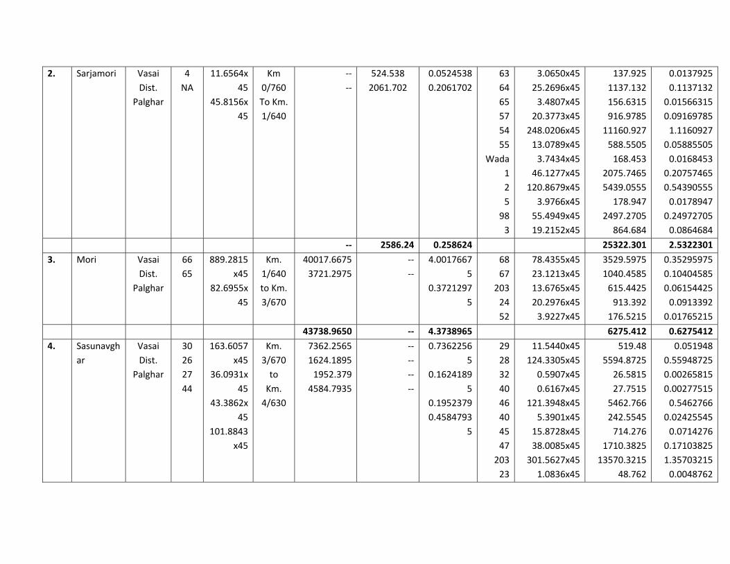
2. Sarjamori Vasai
Dist.
Palghar
4
NA
11.6564x
45
45.8156x
45
Km
0/760
To Km.
1/640
‐‐
‐‐
524.538
2061.702
0.0524538
0.2061702
63
64
65
57
54
55
Wada
1
2
5
98
3
3.0650x45
25.2696x45
3.4807x45
20.3773x45
248.0206x45
13.0789x45
3.7434x45
46.1277x45
120.8679x45
3.9766x45
55.4949x45
19.2152x45
137.925
1137.132
156.6315
916.9785
11160.927
588.5505
168.453
2075.7465
5439.0555
178.947
2497.2705
864.684
0.0137925
0.1137132
0.01566315
0.09169785
1.1160927
0.05885505
0.0168453
0.20757465
0.54390555
0.0178947
0.24972705
0.0864684
‐‐ 2586.24 0.258624 25322.301 2.5322301
3. Mori Vasai
Dist.
Palghar
66
65
889.2815
x45
82.6955x
45
Km.
1/640
to Km.
3/670
40017.6675
3721.2975
‐‐
‐‐
4.0017667
5
0.3721297
5
68
67
203
24
52
78.4355x45
23.1213x45
13.6765x45
20.2976x45
3.9227x45
3529.5975
1040.4585
615.4425
913.392
176.5215
0.35295975
0.10404585
0.06154425
0.0913392
0.01765215
43738.9650 ‐‐ 4.3738965 6275.412 0.6275412
4. Sasunavgh
ar
Vasai
Dist.
Palghar
30
26
27
44
163.6057
x45
36.0931x
45
43.3862x
45
101.8843
x45
Km.
3/670
to
Km.
4/630
7362.2565
1624.1895
1952.379
4584.7935
‐‐
‐‐
‐‐
‐‐
0.7362256
5
0.1624189
5
0.1952379
0.4584793
5
29
28
32
40
46
40
45
47
203
23
11.5440x45
124.3305x45
0.5907x45
0.6167x45
121.3948x45
5.3901x45
15.8728x45
38.0085x45
301.5627x45
1.0836x45
519.48
5594.8725
26.5815
27.7515
5462.766
242.5545
714.276
1710.3825
13570.3215
48.762
0.051948
0.55948725
0.00265815
0.00277515
0.5462766
0.02425545
0.0714276
0.17103825
1.35703215
0.0048762

15523.6185 ‐‐ 1.5523618
5
27917.748 2.7917748
5. Nagale Vasai
Dist.
Palghar
73/1
73/2
73/3
282.8660
x45
203.9783
x45
8.89477x
45
Km.
4/630
to
Km.
6/775
‐‐
‐‐
‐‐
12728.97
9179.0235
400.26465
1.272897
0.9179023
5
0.0400264
65
38
37
00
59
34
35
33
32
66
30
29
28
25
Pada
27
10
23
26
48
49
50
51/8
51/9
51/10
4A
51/1
53
79
11.0187x45
15.8435x45
53.5622x45
36.5864x45
19.3024x45
55.6708x45
165.7222x45
42.4267x45
16.0869x45
226.9186x45
8.9483x45
115.4633x45
4.3571x45
34.8399x45
144.5414x45
7.0618x45
10.0586x45
84.3133x45
59.0482x45
108.7353x45
23.8946x45
104.5127x45
11.2506x45
11.8113x45
42.0764x45
15.0309x45
37.1103x45
25.0142x45
495.8415
712.9575
2410.299
1646.388
868.608
2505.186
7457.499
1909.2015
723.9105
10211.337
402.6735
5195.8485
196.0695
1567.7955
6504.363
317.781
452.6370
3794.0985
2657.169
4893.0885
1075.257
4703.0715
506.277
531.5085
1893.438
676.3905
1669.9635
1125.639
0.04958415
0.07129575
0.2410299
0.1646388
0.0868608
0.2505186
0.7457499
0.19092015
0.07239105
1.0211337
0.04026735
0.51958485
0.01960695
0.15677955
0.6504363
0.0317781
0.0452637
0.37940985
0.2657169
0.48930885
0.1075257
0.47030715
0.0506277
0.05315085
0.1893438
0.06763905
0.16699635
0.1125639

52
71
138.7814x45
0.6067x45
6245.163
27.3015
0.6245163
0.00273015
‐‐ 22308.2581
5
2.2308258
15
73376.7615 7.33767615
6. Shillottar Vasai
Dist.
Palghar
23 1.2443x4
5
Km.
6/775
to
Km.
6/776
‐‐ 55.9935 0.0055993
5
‐‐ ‐‐ ‐‐ ‐‐
‐‐ 55.9935 0.0055993
5
‐‐ ‐‐ ‐‐ ‐‐
Total Area 35314.28 9.4576872
15
168256.845 16.8257025
7. Paye Bhivandi
Dist.
Thane
05A
14
13
12
11
5
10
212
208
205
189
190
191
192
196
193
179
52.0285x
99
58.0660x
99
22.7359x
99
126.2624
x99
52.7893x
99
227.4612
x99
37.7314x
99
118.0054
x99
Km.
6/776
to
Km.
8/701
‐‐
‐‐
‐‐
‐‐
5150.8215
5748.534
2250.8541
12499.9776
5226.1407
22518.6588
3735.4086
11682.5346
11366.2692
13374.6129
1404.5031
13093.0173
13825.8648
6866.5509
321.8193
8033.2263
35.0955
0.5150821
5
0.5748534
0
0.2250854
1
1.2499977
6
0.5226140
7
2.2518658
8
0.3735408
6
1.1682534
6
16
15
23
210
207
17
117.8651x99
35.2787x99
29.9159x99
147.8554x99
10.1359x99
74.0042x99
11668.6449
3492.5913
2961.6741
14637.6846
1003.4541
7326.4158
1.16686449
0.34925913
0.29616741
1.46376846
0.10034541
0.73264158

NA1
NA2
114.8108
x99
135.0971
x99
14.1869x
99
132.2527
x99
139.6552
x99
69.3591x
99
3.2507x9
9
81.1437x
99
0.3545x9
9
74.6964x
99
14.6823x
99
7394.9436
1453.5477
1.1366269
2
1.3374612
9
0.1404503
1
1.3093017
3
1.3825864
8
0.6866550
9
0.0321819
3
0.8033226
3
0.0035095
5
0.7394943
6
0.1453547
7
145982.380
5
14.598238
1
41090.4648 4.10904648
8. Payegaon Bhivandi
Dist.
Thane
NA
17/0
1
68
69
33.3110x
99
47.8421x
99
153.9544
x99
Km.
8/701
to
Km.
9/621
3297.7890
4736.3679
15241.4856
12607.9767
0.3297789
0
0.4736367
9
1.5241485
6
68
82
72
74
76
75
153.9543x99
20.6471x99
76.8526x99
5.8420x99
258.7615x99
1.7394x99
15241.4757
2044.0629
7608.4074
578.3580
25617.3885
172.2006
1.52414757
0.20440629
0.76084074
0.05783580
2.56173885
0.01722006
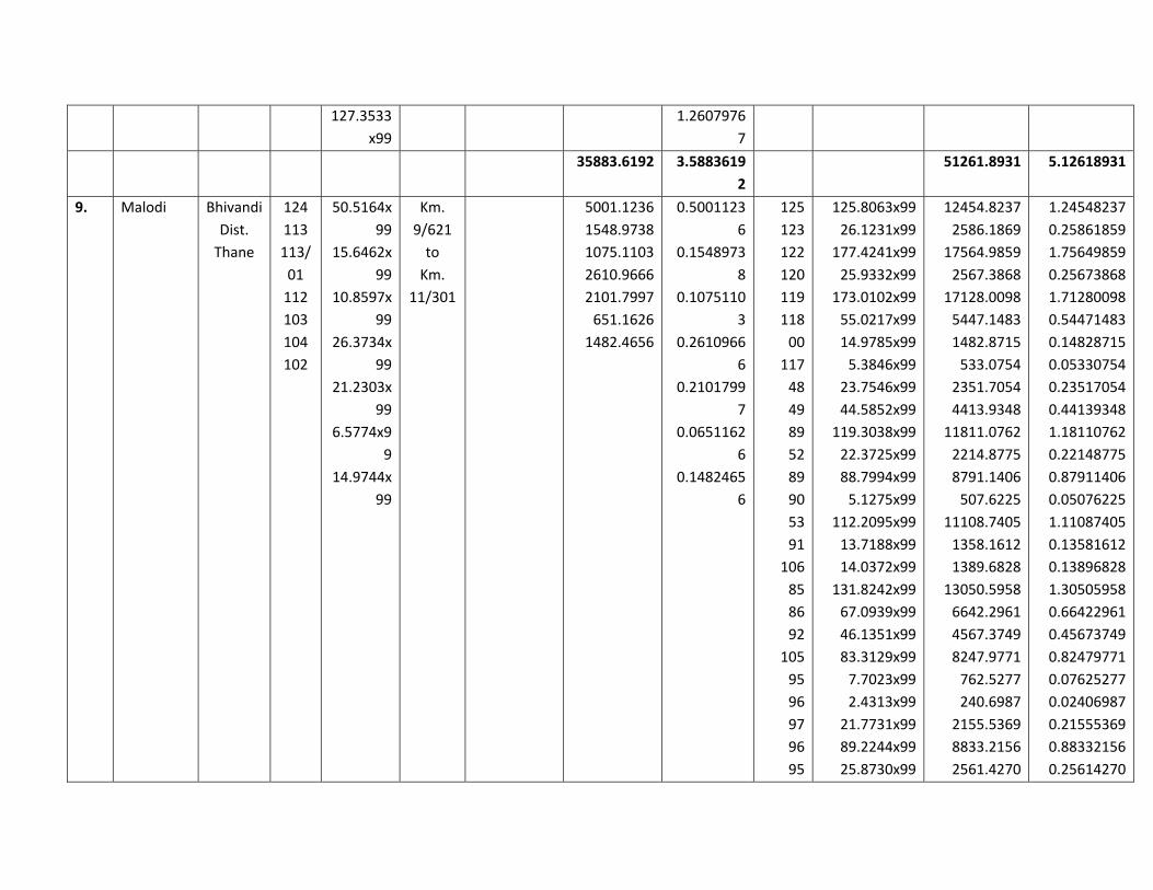
127.3533
x99
1.2607976
7
35883.6192 3.5883619
2
51261.8931 5.12618931
9. Malodi Bhivandi
Dist.
Thane
124
113
113/
01
112
103
104
102
50.5164x
99
15.6462x
99
10.8597x
99
26.3734x
99
21.2303x
99
6.5774x9
9
14.9744x
99
Km.
9/621
to
Km.
11/301
5001.1236
1548.9738
1075.1103
2610.9666
2101.7997
651.1626
1482.4656
0.5001123
6
0.1548973
8
0.1075110
3
0.2610966
6
0.2101799
7
0.0651162
6
0.1482465
6
125
123
122
120
119
118
00
117
48
49
89
52
89
90
53
91
106
85
86
92
105
95
96
97
96
95
125.8063x99
26.1231x99
177.4241x99
25.9332x99
173.0102x99
55.0217x99
14.9785x99
5.3846x99
23.7546x99
44.5852x99
119.3038x99
22.3725x99
88.7994x99
5.1275x99
112.2095x99
13.7188x99
14.0372x99
131.8242x99
67.0939x99
46.1351x99
83.3129x99
7.7023x99
2.4313x99
21.7731x99
89.2244x99
25.8730x99
12454.8237
2586.1869
17564.9859
2567.3868
17128.0098
5447.1483
1482.8715
533.0754
2351.7054
4413.9348
11811.0762
2214.8775
8791.1406
507.6225
11108.7405
1358.1612
1389.6828
13050.5958
6642.2961
4567.3749
8247.9771
762.5277
240.6987
2155.5369
8833.2156
2561.4270
1.24548237
0.25861859
1.75649859
0.25673868
1.71280098
0.54471483
0.14828715
0.05330754
0.23517054
0.44139348
1.18110762
0.22148775
0.87911406
0.05076225
1.11087405
0.13581612
0.13896828
1.30505958
0.66422961
0.45673749
0.82479771
0.07625277
0.02406987
0.21555369
0.88332156
0.25614270

14471.6022 1.4471602
2
150773.0796 15.0773079
10. Kharbhav Bhivandi
Dist.
Thane
98
99
95
92
93
71‐
83
70
9
15
NA
70.5257x
99
38.8778x
99
49.8696x
99
76.9577x
99
26.5188x
99
315.6441
x99
32.5908x
99
37.9754x
99
107.4124
x99
32.4742x
99
Km.
11/301
to
Km.
13/541
6982.0443
3848.9022
4937.0904
7618.8123
2625.3612
31248.7659
3226.4892
3759.5646
10633.8276
3214.9458
0.6982044
3
0.3848902
2
0.4937090
4
0.7618812
3
0.2625361
2
3.1248765
9
0.3226489
2
0.3759564
5
1.0633827
6
0.3214945
8
00
101
100
69
68
111
67
64
66
62
63/01
58
59
12
00
11
10
14
16
00
274.4905x99
7.8813x99
39.1013x99
35.8319x99
107.7236x99
107.7236x99
10.8154x99
23.3235x99
0.9144x99
160.4184x99
5.0135x99
63.9190x99
36.8110x99
98.8577x99
14.2886x99
61.8604x99
64.1790x99
27.2077x99
2.1282x99
32.1402x99
27174.5595
780.2487
3871.0287
3547.3581
10664.6364
10664.6364
1070.7246
2309.0265
90.5256
15881.4216
496.3365
6327.9810
3644.2890
9786.9123
1414.5714
6124.1796
6353.7210
2693.5623
210.6918
3181.8798
2.71745595
0.07802487
0.38710287
0.35473581
1.06646364
1.06646364
0.10707246
0.23090265
0.00905256
1.58814216
0.04963365
0.63279810
0.36442890
0.97869123
0.14145714
0.61241796
0.63537210
0.26935623
0.02106918
0.31818798
78095.8035 7.8095803
4
116288.2908 11.62882908
11. Wadungh
ar
Bhivandi
Dist.
Thane
292
F
NA1
NA2
259.7973
x99
30.7400x
99
55.4750x
99
Km
13/541
to
Km.
14/301
25719.9327
3043.2600
5492.0250
2.5719932
7
0.3043260
0
0.5492025
0
‐‐ ‐‐ ‐‐

25719.9327 8535.2850 3.4255217
7
12. Dunge Bhivandi
Dist.
Thane
NA
113
96
95
113A
‐1A‐
1
97
100
48.8014x
99
71.7946x
99
42.9856x
99
67.3221x
99
24.7538x
99
57.6447x
99
51.7433x
99
Km.
14/301
to
Km.
15/621
4831.3386
7107.6654
4255.5744
6664.8879
2450.6262
5706.8253
5122.5867
0.4831338
6
0.7107665
4
0.4255574
4
0.6664887
9
0.2450626
2
0.5706825
3
0.5122586
7
102
101
83
Dunge
72
73
79
74
77
75
76
14.2056x99
111.4402x99
7.0664x99
269.7568x99
9.8310x99
69.5656x99
136.3666x99
47.6175x99
48.5809x99
46.6596x99
83.6147x99
1406.3544
11032.5798
699.5736
26705.9232
973.2690
6886.9944
13500.2934
4714.1325
4809.5091
4619.3004
8277.8553
0.14063544
1.10325798
0.06995736
2.67059232
0.09732690
0.68869944
1.35002934
0.47141325
0.48095091
0.46193004
0.82778553
36139.5045 3.6139504
5
83625.7851 8.36257851
13. Kewani Bhivandi
Dist.
Thane
181
13
134
21
233.0047
x99
56.2299x
99
51.9859x
99
21.6423x
99
Km.
15/621
to
Km.
17/421
23067.4653
5566.7601
5146.6041
2142.5877
2.3067465
3
0.5566760
1
0.5146604
1
0.2142587
7
12
135
00
131
132
129
102
178
127
128
126
125
27.4674x99
47.3543x99
2.9158x99
59.4892x99
6.8801x99
10.3176x99
1.5492x99
1.0907x99
36.9432x99
11.7759x99
9.5076x99
50.1185x99
2719.2726
4688.0757
288.6642
5889.4308
681.1299
1021.4424
153.3708
107.9793
3657.3768
1165.8141
941.2524
4961.7315
0.27192726
0.46880757
0.02886642
0.58894308
0.06811299
0.10214424
0.01533708
0.01079793
0.36573768
0.11658141
0.09412524
0.49617315
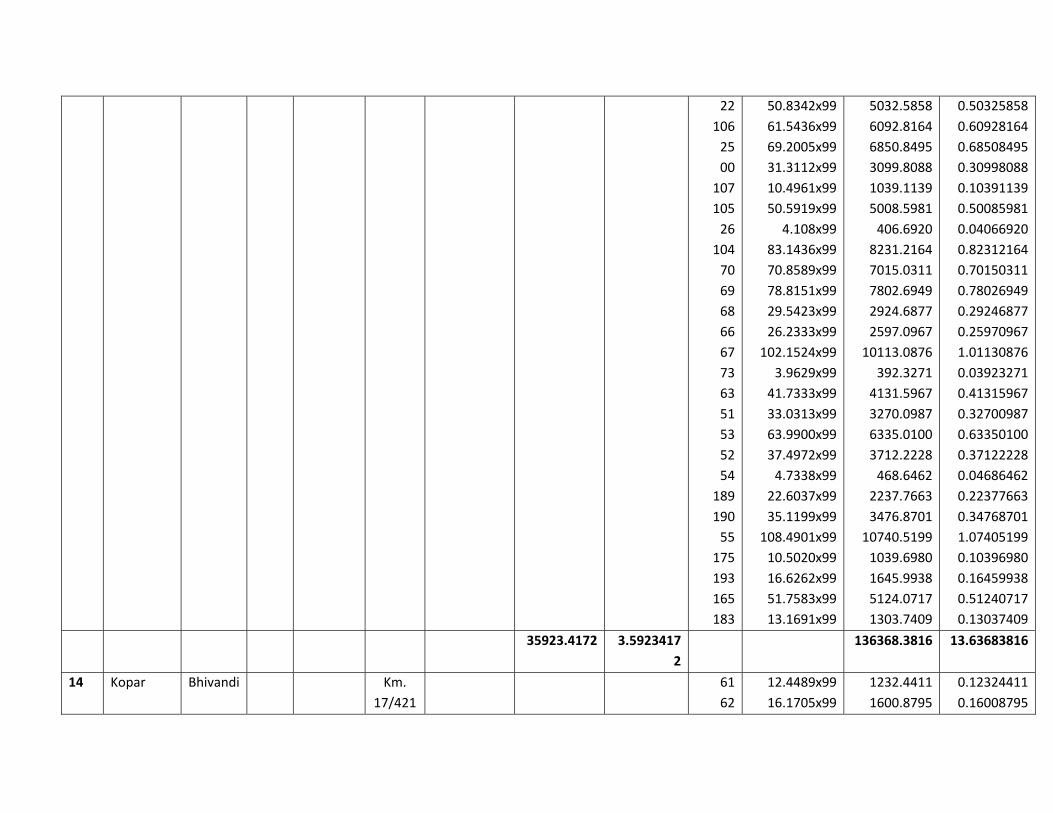
22
106
25
00
107
105
26
104
70
69
68
66
67
73
63
51
53
52
54
189
190
55
175
193
165
183
50.8342x99
61.5436x99
69.2005x99
31.3112x99
10.4961x99
50.5919x99
4.108x99
83.1436x99
70.8589x99
78.8151x99
29.5423x99
26.2333x99
102.1524x99
3.9629x99
41.7333x99
33.0313x99
63.9900x99
37.4972x99
4.7338x99
22.6037x99
35.1199x99
108.4901x99
10.5020x99
16.6262x99
51.7583x99
13.1691x99
5032.5858
6092.8164
6850.8495
3099.8088
1039.1139
5008.5981
406.6920
8231.2164
7015.0311
7802.6949
2924.6877
2597.0967
10113.0876
392.3271
4131.5967
3270.0987
6335.0100
3712.2228
468.6462
2237.7663
3476.8701
10740.5199
1039.6980
1645.9938
5124.0717
1303.7409
0.50325858
0.60928164
0.68508495
0.30998088
0.10391139
0.50085981
0.04066920
0.82312164
0.70150311
0.78026949
0.29246877
0.25970967
1.01130876
0.03923271
0.41315967
0.32700987
0.63350100
0.37122228
0.04686462
0.22377663
0.34768701
1.07405199
0.10396980
0.16459938
0.51240717
0.13037409
35923.4172 3.5923417
2
136368.3816 13.63683816
14 Kopar Bhivandi Km.
17/421
61
62
12.4489x99
16.1705x99
1232.4411
1600.8795
0.12324411
0.16008795
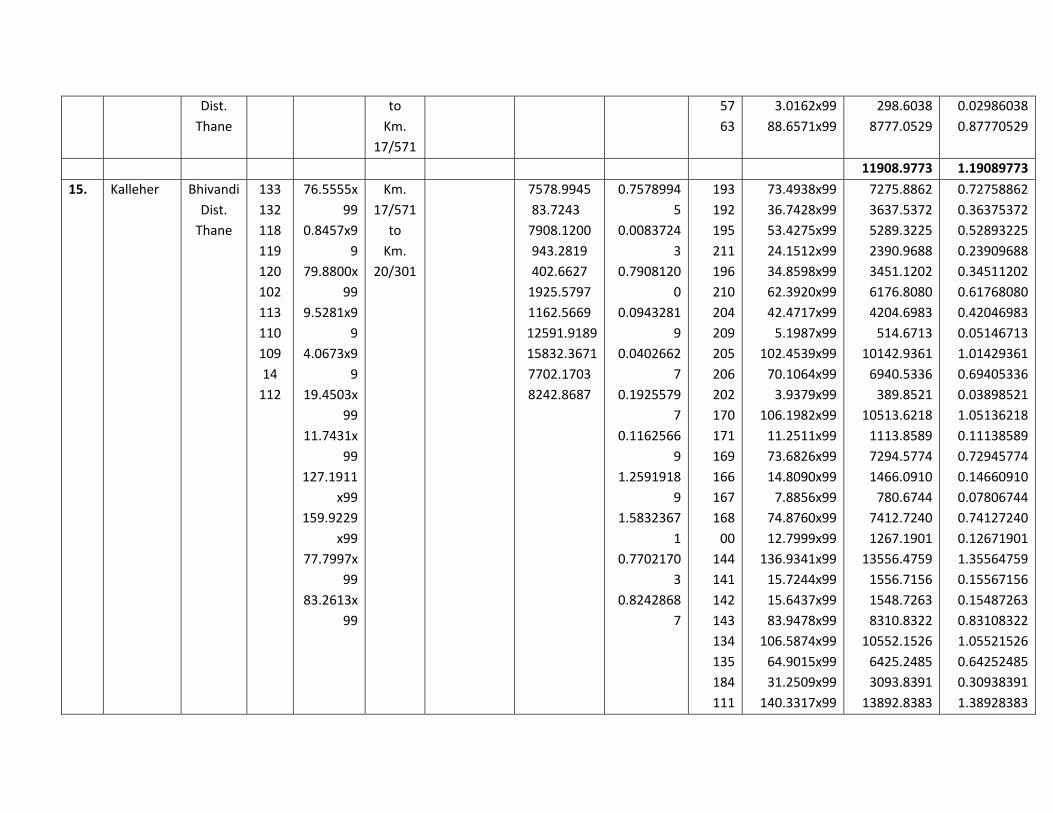
Dist.
Thane
to
Km.
17/571
57
63
3.0162x99
88.6571x99
298.6038
8777.0529
0.02986038
0.87770529
11908.9773 1.19089773
15. Kalleher Bhivandi
Dist.
Thane
133
132
118
119
120
102
113
110
109
14
112
76.5555x
99
0.8457x9
9
79.8800x
99
9.5281x9
9
4.0673x9
9
19.4503x
99
11.7431x
99
127.1911
x99
159.9229
x99
77.7997x
99
83.2613x
99
Km.
17/571
to
Km.
20/301
7578.9945
83.7243
7908.1200
943.2819
402.6627
1925.5797
1162.5669
12591.9189
15832.3671
7702.1703
8242.8687
0.7578994
5
0.0083724
3
0.7908120
0
0.0943281
9
0.0402662
7
0.1925579
7
0.1162566
9
1.2591918
9
1.5832367
1
0.7702170
3
0.8242868
7
193
192
195
211
196
210
204
209
205
206
202
170
171
169
166
167
168
00
144
141
142
143
134
135
184
111
73.4938x99
36.7428x99
53.4275x99
24.1512x99
34.8598x99
62.3920x99
42.4717x99
5.1987x99
102.4539x99
70.1064x99
3.9379x99
106.1982x99
11.2511x99
73.6826x99
14.8090x99
7.8856x99
74.8760x99
12.7999x99
136.9341x99
15.7244x99
15.6437x99
83.9478x99
106.5874x99
64.9015x99
31.2509x99
140.3317x99
7275.8862
3637.5372
5289.3225
2390.9688
3451.1202
6176.8080
4204.6983
514.6713
10142.9361
6940.5336
389.8521
10513.6218
1113.8589
7294.5774
1466.0910
780.6744
7412.7240
1267.1901
13556.4759
1556.7156
1548.7263
8310.8322
10552.1526
6425.2485
3093.8391
13892.8383
0.72758862
0.36375372
0.52893225
0.23909688
0.34511202
0.61768080
0.42046983
0.05146713
1.01429361
0.69405336
0.03898521
1.05136218
0.11138589
0.72945774
0.14660910
0.07806744
0.74127240
0.12671901
1.35564759
0.15567156
0.15487263
0.83108322
1.05521526
0.64252485
0.30938391
1.38928383
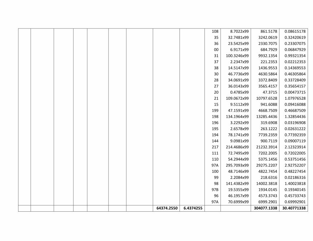
108
35
36
00
31
37
38
30
28
27
20
21
15
199
198
196
195
194
144
217
111
110
97A
100
99
98
97B
96
97A
8.7022x99
32.7481x99
23.5425x99
6.9171x99
100.3246x99
2.2347x99
14.5147x99
46.7736x99
34.0691x99
36.0143x99
0.4785x99
109.0672x99
9.5112x99
47.1591x99
134.1964x99
3.2292x99
2.6578x99
78.1741x99
9.0981x99
214.4686x99
72.7495x99
54.2944x99
295.7093x99
48.7146x99
2.2084x99
141.4382x99
19.5355x99
46.1957x99
70.6999x99
861.5178
3242.0619
2330.7075
684.7929
9932.1354
221.2353
1436.9553
4630.5864
3372.8409
3565.4157
47.3715
10797.6528
941.6088
4668.7509
13285.4436
319.6908
263.1222
7739.2359
900.7119
21232.3914
7202.2005
5375.1456
29275.2207
4822.7454
218.6316
14002.3818
1934.0145
4573.3743
6999.2901
0.08615178
0.32420619
0.23307075
0.06847929
0.99321354
0.02212353
0.14369553
0.46305864
0.33728409
0.35654157
0.00473715
1.07976528
0.09416088
0.46687509
1.32854436
0.03196908
0.02631222
0.77392359
0.09007119
2.12323914
0.72022005
0.53751456
2.92752207
0.48227454
0.02186316
1.40023818
0.19340145
0.45733743
0.69992901
64374.2550 6.4374255 304077.1338 30.40771338

16. Kasheli Bhivandi
Dist.
Thane
199
198
112
110
111
97
100
98
97A
47.1592x
99
134.1964
x99
83.2595x
99
54.2945x
99
72.7496x
99
19.5355x
99
48.7146x
99
141.4382
x99
295.7094
x99
Km.
20/301
to
Km.
21/931
4668.7608
13285.4436
8242.6905
5375.1555
7202.2104
1934.0145
4822.7454
14002.3818
29275.2306
0.4668760
8
1.3285443
6
0.8242690
5
0.5375155
5
0.7202210
4
0.1934014
5
0.4822745
4
1.4002381
8
2.9275230
6
‐‐ ‐‐ ‐‐
88808.6331 8.8808633
1
‐‐ ‐‐ ‐‐
17. Dive Bhivandi
Dist.
Thane
NA
146
140
148
42.9231x
99
3.5558x9
9
71.2288x
99
1.1953x9
9
Km.
21/931
to
Km.
22/741
4249.3869
352.0242
7051.6512
118.3347
0.4249386
9
0.0352024
2
0.7051651
2
0.0118334
7
‐‐ ‐‐ ‐‐
11771.3970 1.1771397 ‐‐ ‐‐ ‐‐
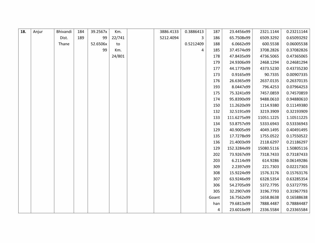
18. Anjur Bhivandi
Dist.
Thane
184
189
39.2567x
99
52.6506x
99
Km.
22/741
to
Km.
24/801
3886.4133
5212.4094
0.3886413
3
0.5212409
4
187
186
188
185
178
179
177
173
176
193
175
174
150
132
133
134
129
135
136
129
202
203
309
308
307
306
305
Goant
han
4
23.4456x99
65.7508x99
6.0662x99
37.4574x99
47.8435x99
24.9306x99
44.1770x99
0.9165x99
26.6365x99
8.0447x99
75.3241x99
95.8390x99
11.2620x99
32.5191x99
111.6275x99
53.8757x99
40.9005x99
17.7278x99
21.4003x99
152.3284x99
73.9267x99
6.2114x99
2.2397x99
15.9224x99
63.9246x99
54.2705x99
32.2907x99
16.7562x99
79.6813x99
23.6016x99
2321.1144
6509.3292
600.5538
3708.2826
4736.5065
2468.1294
4373.5230
90.7335
2637.0135
796.4253
7457.0859
9488.0610
1114.9380
3219.3909
11051.1225
5333.6943
4049.1495
1755.0522
2118.6297
15080.5116
7318.7433
614.9286
221.7303
1576.3176
6328.5354
5372.7795
3196.7793
1658.8638
7888.4487
2336.5584
0.23211144
0.65093292
0.06005538
0.37082826
0.47365065
0.24681294
0.43735230
0.00907335
0.26370135
0.07964253
0.74570859
0.94880610
0.11149380
0.32193909
1.10511225
0.53336943
0.40491495
0.17550522
0.21186297
1.50805116
0.73187433
0.06149286
0.02217303
0.15763176
0.63285354
0.53727795
0.31967793
0.16588638
0.78884487
0.23365584

12
5
11
13
14
24
23
15
17
18
17
19
20
49.4923x99
116.8247x99
1.1911x99
29.8345x99
1.2410x99
113.7218x99
12.3563x99
77.3079x99
14.0757x99
4.3848x99
20.1823x99
1.1024x99
4899.7377
11565.6453
117.9189
2953.6155
122.8590
11258.4582
1223.2737
7653.4821
1393.4943
434.0952
1998.0477
109.1376
0.48997377
1.15656453
0.01179189
0.29536155
0.01228590
1.12584582
0.12232737
0.76534821
0.13934943
0.04340952
0.19980477
0.01091376
9098.8227 0.9098822
7
169152.6969 16.91526969
19. Bharodi Bhivandi
Dist.
Thane
92
106
107
108
120
119
121
117
115
116
37.4345x
99
10.0711x
99
68.7619x
99
105.1555
x99
20.4208x
99
35.8567x
99
8.6134x9
9
Km.
24/801
to
Km.
26/951
3706.0155
997.0389
6807.4281
10410.386
2021.6592
3549.8133
852.7266
6673.4316
6677.6886
2582.2467
0.3706015
5
0.0997038
9
0.6807428
1
1.0410386
0.2021659
2
0.3549813
3
0.0852726
6
0.6673431
6
202
201
210
200
211
212
213
214
215
219
224
223
8
4
3
1.0673x99
107.5334x99
9.0555x99
22.5607x99
7.9522x99
57.9017x99
2.5720x99
0.4271x99
26.8561x99
45.9052x99
108.6781x99
34.7432x99
52.2875x99
38.6671x99
64.6327x99
105.6627
10645.8066
896.4945
2233.5093
787.2678
5732.2683
254.6280
42.2829
2658.7539
4544.6148
10759.1319
3439.5768
5176.4625
3828.0429
6398.6373
0.01056627
1.06458066
0.08964945
0.22335093
0.07872678
0.57322683
0.02546280
0.00422829
0.26587539
0.45446148
1.07591319
0.34395768
0.51764625
0.38280429
0.63986373

67.4084x
99
67.4514x
99
26.0833x
99
0.6677688
6
0.2582246
7
2
94
95
96
85
00
73
118
0.3339x99
88.8953x99
6.3123x99
88.2527x99
14.8820x99
155.5633x99
90.8828x99
81.6212x99
33.0561
8800.6347
624.9177
8737.0173
1473.3180
15400.7667
8997.3972
8080.4988
0.00330561
0.88006347
0.06249177
0.87370173
0.14733180
1.54007667
0.89973972
0.80804988
44278.4345 4.4278434
5
109650.7467 10.9650747
20. Bhopar Kalyan
Dist
Thane
172
261
151
150
149
126
141
127
128
49.0805x
99
39.6346x
99
47.0804x
99
62.9828x
99
74.7435x
99
59.6017x
99
11.2679x
99
111.9267
x99
36.5885x
99
Km.
26/951
to
Km.
28/951
4858.9695
3923.8254
4660.9596
6235.2972
7399.6065
5900.5683
1115.5221
11080.7433
3622.2615
0.4858969
5
0.3923825
4
0.4660959
6
0.6235297
2
0.7399606
5
0.5900568
3
0.1115522
1
1.1080743
3
0.3622261
5
‐‐ ‐‐ ‐‐ ‐‐
48797.7534 4.8797753
4
‐‐ ‐‐ ‐‐ ‐‐

21 Sandap Kalyan
Dist
Thane
Km.
28/951
to Km.
29/231
22 Usarghar Kalyan
Dist
Thane
Km.
29/231
to
Km.
30/131
23 Gharivali Kalyan
Dist
Thane
Km.
30/131
to
Km.
30/441
24 Katai Kalyan
Dist
Thane
30/441
to
30/741
25 Koegaon Kalyan
Dist
Thane
Km.
30/741
to Km.
31/721
26 Hendutan
e
Kalyan
Dist
Thane
Km.
31/721
to Km.
33/211
27 Shirdhon Kalyan
Dist
Thane
Km
33/211
to
91
95
122
123
24.5544x99
138.5887x99
34.5927x99
8.7671x99
2430.8856
13720.2813
3424.6773
867.9429
0.24308856
1.37202813
0.34246773
0.08679429
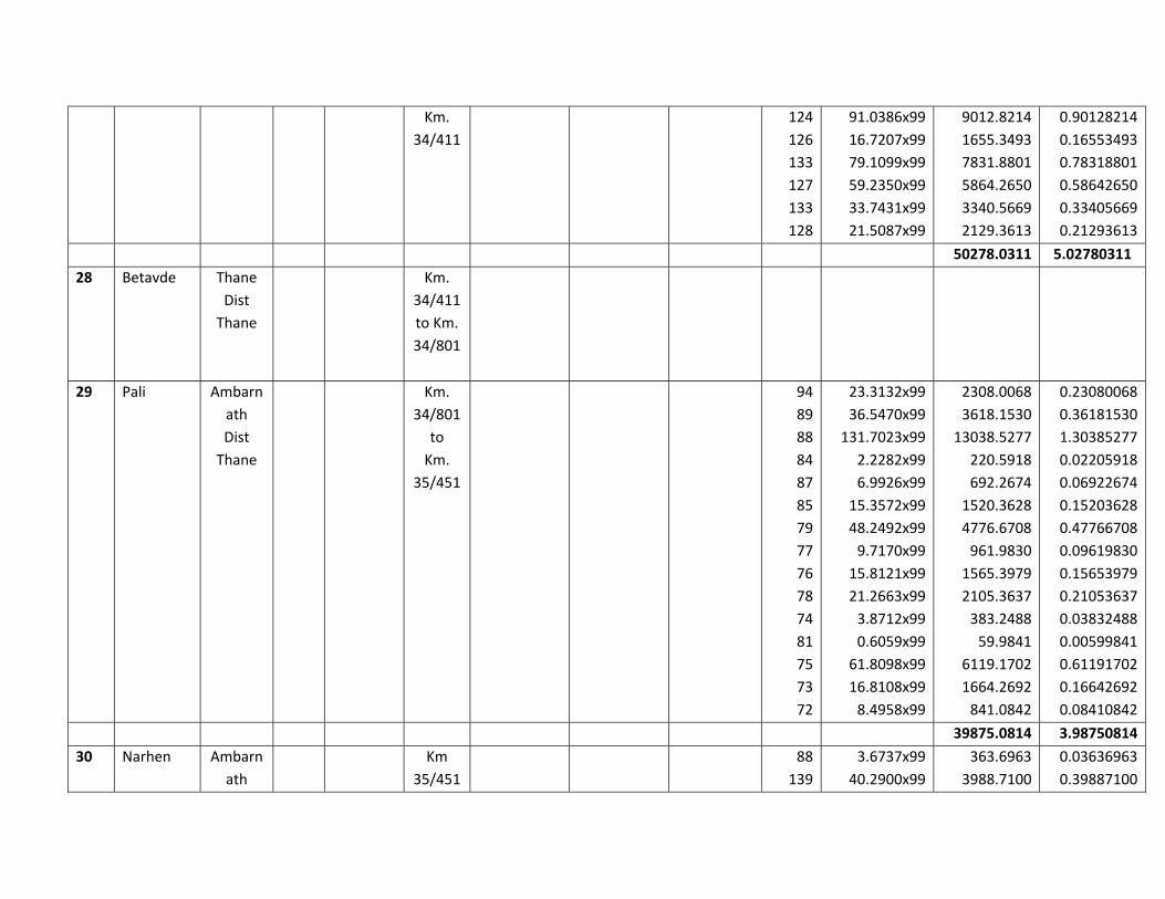
Km.
34/411
124
126
133
127
133
128
91.0386x99
16.7207x99
79.1099x99
59.2350x99
33.7431x99
21.5087x99
9012.8214
1655.3493
7831.8801
5864.2650
3340.5669
2129.3613
0.90128214
0.16553493
0.78318801
0.58642650
0.33405669
0.21293613
50278.0311 5.02780311
28 Betavde Thane
Dist
Thane
Km.
34/411
to Km.
34/801
29 Pali Ambarn
ath
Dist
Thane
Km.
34/801
to
Km.
35/451
94
89
88
84
87
85
79
77
76
78
74
81
75
73
72
23.3132x99
36.5470x99
131.7023x99
2.2282x99
6.9926x99
15.3572x99
48.2492x99
9.7170x99
15.8121x99
21.2663x99
3.8712x99
0.6059x99
61.8098x99
16.8108x99
8.4958x99
2308.0068
3618.1530
13038.5277
220.5918
692.2674
1520.3628
4776.6708
961.9830
1565.3979
2105.3637
383.2488
59.9841
6119.1702
1664.2692
841.0842
0.23080068
0.36181530
1.30385277
0.02205918
0.06922674
0.15203628
0.47766708
0.09619830
0.15653979
0.21053637
0.03832488
0.00599841
0.61191702
0.16642692
0.08410842
39875.0814 3.98750814
30 Narhen Ambarn
ath
Km
35/451
88
139
3.6737x99
40.2900x99
363.6963
3988.7100
0.03636963
0.39887100
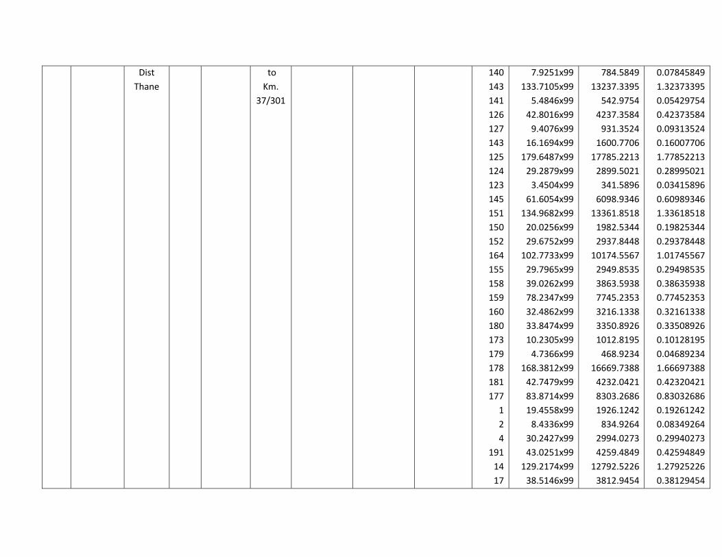
Dist
Thane
to
Km.
37/301
140
143
141
126
127
143
125
124
123
145
151
150
152
164
155
158
159
160
180
173
179
178
181
177
1
2
4
191
14
17
7.9251x99
133.7105x99
5.4846x99
42.8016x99
9.4076x99
16.1694x99
179.6487x99
29.2879x99
3.4504x99
61.6054x99
134.9682x99
20.0256x99
29.6752x99
102.7733x99
29.7965x99
39.0262x99
78.2347x99
32.4862x99
33.8474x99
10.2305x99
4.7366x99
168.3812x99
42.7479x99
83.8714x99
19.4558x99
8.4336x99
30.2427x99
43.0251x99
129.2174x99
38.5146x99
784.5849
13237.3395
542.9754
4237.3584
931.3524
1600.7706
17785.2213
2899.5021
341.5896
6098.9346
13361.8518
1982.5344
2937.8448
10174.5567
2949.8535
3863.5938
7745.2353
3216.1338
3350.8926
1012.8195
468.9234
16669.7388
4232.0421
8303.2686
1926.1242
834.9264
2994.0273
4259.4849
12792.5226
3812.9454
0.07845849
1.32373395
0.05429754
0.42373584
0.09313524
0.16007706
1.77852213
0.28995021
0.03415896
0.60989346
1.33618518
0.19825344
0.29378448
1.01745567
0.29498535
0.38635938
0.77452353
0.32161338
0.33508926
0.10128195
0.04689234
1.66697388
0.42320421
0.83032686
0.19261242
0.08349264
0.29940273
0.42594849
1.27925226
0.38129454

13
20
19
18
192
21
90.2040x99
90.2348x99
36.6244x99
2.0908x99
10.7170x99
9.6608x99
8930.1960
8933.2452
3625.8156
206.9892
1060.9830
956.4192
0.89301960
0.89332452
0.36258156
0.02069892
0.10609830
0.09564192
183415.0032 18.34150032
31 Karwale Ambarn
ath
Dist
Thane
Km.
37/301
to
Km.
39/271
58
60
61
63
55
54
53
52
65
51
66
72
49
68
48
6P
47
46
44
43
45
42
41
44.7876x99
83.8119x99
114.1804x99
119.7943x99
43.4760x99
61.5243x99
2.3063x99
29.4818x99
37.1265x99
103.2333x99
71.7851x99
1.1120x99
83.2674x99
2.1709x99
68.2333x99
0.5657x99
122.5806x99
5.7913x99
151.1453x99
26.2722x99
28.1834x99
6.7542x99
238.1921x99
4433.9724
8297.3781
11303.8596
11859.6357
4304.1240
6090.9057
228.3237
2918.6982
3675.5235
10220.0967
7106.7249
110.0880
8243.4726
214.9191
6755.0967
56.0043
12135.4794
573.3387
14963.3847
2600.9478
2790.1566
668.6658
23581.0179
0.44339724
0.82973781
1.13038596
1.18596357
0.43041240
0.60909057
0.02283237
0.29186982
0.36755235
1.02200967
0.71067249
0.01100880
0.82434726
0.02149191
0.67550967
0.00560043
1.21354794
0.05733387
1.49633847
0.26009478
0.27901566
0.06686658
2.35810179
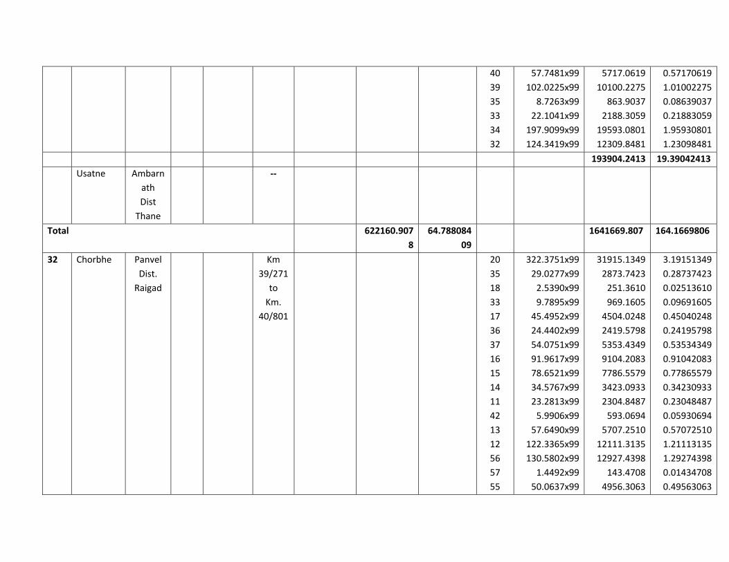
40
39
35
33
34
32
57.7481x99
102.0225x99
8.7263x99
22.1041x99
197.9099x99
124.3419x99
5717.0619
10100.2275
863.9037
2188.3059
19593.0801
12309.8481
0.57170619
1.01002275
0.08639037
0.21883059
1.95930801
1.23098481
193904.2413 19.39042413
Usatne Ambarn
ath
Dist
Thane
‐‐
Total 622160.907
8
64.788084
09
1641669.807 164.1669806
32 Chorbhe Panvel
Dist.
Raigad
Km
39/271
to
Km.
40/801
20
35
18
33
17
36
37
16
15
14
11
42
13
12
56
57
55
322.3751x99
29.0277x99
2.5390x99
9.7895x99
45.4952x99
24.4402x99
54.0751x99
91.9617x99
78.6521x99
34.5767x99
23.2813x99
5.9906x99
57.6490x99
122.3365x99
130.5802x99
1.4492x99
50.0637x99
31915.1349
2873.7423
251.3610
969.1605
4504.0248
2419.5798
5353.4349
9104.2083
7786.5579
3423.0933
2304.8487
593.0694
5707.2510
12111.3135
12927.4398
143.4708
4956.3063
3.19151349
0.28737423
0.02513610
0.09691605
0.45040248
0.24195798
0.53534349
0.91042083
0.77865579
0.34230933
0.23048487
0.05930694
0.57072510
1.21113135
1.29274398
0.01434708
0.49563063

68
53
49
Wadi
50
52
26.3008x99
115.2157x99
28.4025x99
29.1362x99
24.3113x99
28.1898x99
2603.7792
11406.3543
2811.8475
2884.4838
2406.8187
2790.7902
0.26037792
1.14063543
0.28118475
0.28844838
0.24068187
0.27907902
132248.0709 13.22480709
33 Nitale Panvel
Dist.
Raigad
Km.
40/801
to
Km.
42/371
132
131
130
129
133
128
127
124
125
126
124
102
136
103
136
96
95
94
70
78
80
82
79
35.2014x99
15.60522x99
4.4840x99
151.1502x99
15.8838x99
41.7107x99
61.9308x99
3.4674x99
70.4745x99
131.0050x99
52.6162x99
63.8344x99
4.7194x99
85.4236x99
26.5879x99
117.9727x99
41.9530x99
7.6940x99
33.9484x99
22.6389x99
198.4936x99
32.9951x99
57.4237x99
3484.9386
1544.6178
443.9160
14963.8698
1572.4962
4129.3593
6131.1492
343.2726
6976.9755
12969.4950
5209.0038
6319.6056
467.2206
8456.9364
2632.2021
11679.2973
4153.3470
761.7060
3360.8916
2241.2511
19650.8664
3266.5149
5684.9463
0.34849386
0.15446178
0.04439160
1.49638698
0.15724962
0.41293593
0.61311492
0.03432726
0.69769755
1.29694950
0.52090038
0.63196056
0.04672206
0.84569364
0.26322021
1.16792973
0.41533470
0.07617060
0.33608916
0.22412511
1.96508664
0.32665149
0.56849463

78
35
82
84
1
2
32
3
24
11
23
18
12
13
10
14
15
3.5301x99
118.6974x99
11.5221x99
37.9616x99
41.2185x99
283.4666x99
89.9320x99
44.6288x99
35.4999x99
84.3375x99
8.9828x99
3.0410x99
12.9705x99
127.8633x99
26.3826x99
33.0017x99
3.7593x99
349.4799
11751.0426
1140.6879
3758.1984
4080.6315
28063.1934
8903.2680
4418.2512
3514.4901
8349.4125
889.2972
301.0590
1284.0795
12658.4667
2611.8774
3267.1683
372.1707
0.03494799
1.17510426
0.11406879
0.37581984
0.40806315
2.80631934
0.89032680
0.44182512
0.35144901
0.83494125
0.08892972
0.03010590
0.12840795
1.26584667
0.26118774
0.32671683
0.03721707
222156.6534 22.21566534
34 Wavanje Panvel
Dist.
Raigad
Km.
42/371
to
Km.
44/901
27
21
28
14
44
35
252.4832x99
18.7050x99
12.9678x99
286.4381x99
134.1152x99
77.3935x99
24995.8368
1851.7950
1283.8122
28357.3719
13277.4048
7661.9565
2.49958368
0.18517950
0.12838122
2.83573719
1.32774048
0.76619565
77428.1772 7.74281772
35 Mahodar Panvel
Dist.
Raigad
Km.
44/901
to
Km.
45/501
174
201
200
1/188
2/188
176.4127x99
13.7321x99
5.7679x99
65.1130x99
31.2424x99
17464.8573
1359.4779
571.0221
6446.1870
3092.9976
1.74648573
0.13594779
0.05710221
0.64461870
0.30929976

3/188
1/198
5/198
4/198
186
1/180
00
185
184
1/244
2/244
183
182
240
239
245
1/241
2/241
247
242
1/12
2/12
1/11
2/11
5
3/11
1/10
2/10
4/10
3/10
19.7864x99
4.6074x99
13.3671x99
29.3293x99
17.5212x99
6.5888x99
9.2699x99
56.3633x99
17.8771x99
14.6425x99
77.6973x99
51.4573x99
4.7279x99
42.8281x99
22.7924x99
22.3663x99
49.8030x99
2.5740x99
7.3627x99
52.3648x99
2.5528x99
6.6092x99
65.5638x99
19.2279x99
5.4298x99
25.8180x99
24.1740x99
6.2722x99
35.9146x99
26.8563x99
1958.8536
456.1326
1323.3429
2903.6007
1734.5988
652.2912
917.7201
5579.9667
1769.8329
1449.6075
7692.0327
5094.2727
468.0621
4239.9819
2256.4476
2214.2637
4930.4970
254.8260
728.9073
5184.1152
252.7272
654.3108
6490.8162
1903.5621
537.5502
2555.9820
2393.2260
620.9478
3555.5454
2658.7737
0.19588536
0.04561326
0.13233429
0.29036007
0.17345988
0.06522912
0.09177201
0.55799667
0.17698329
0.14496075
0.76920327
0.50942727
0.04680621
0.42399719
0.22564476
0.22142637
0.49304970
0.02548260
0.07289073
0.51841152
0.02527272
0.06543108
0.64908162
0.19035621
0.05375502
0.25559820
0.23932260
0.06209478
0.35555454
0.26587737

14
Thaku
rwadi
18
20
22
19
56
95.1711x99
17.1217x99
31.0444x99
23.2804x99
13.4961x99
76.9551x99
9.9509x99
9421.9389
1695.0483
3073.3956
2304.7596
1336.1139
7618.5549
985.1391
0.94219389
0.16950483
0.30733956
0.23047596
0.13361139
0.76185549
0.09851391
15317.9631 1.53179631
36 Chndram
inamgaon
Panvel
Dist.
Raigad
Km.
45/501
to
km.
46/221
37 Chinchava
li
Panvel
Dist.
Raigad
Km.
46/221
to
Km.
46/301
0
23
31
30
34
33
34
36
43
36.5824x99
9.3376x99
126.6732x99
6.0534x99
5.9523x99
84.7719x99
70.7247x99
29.4434x99
16.0167x99
3621.6576
924.4224
12540.6468
599.2866
589.2777
8392.4181
7001.7453
2914.8966
1585.6533
0.36216576
0.09244224
1.25406468
0.05992866
0.05892777
0.83924181
0.70017453
0.29148966
0.15856533
38170.0044 3.81700044
38 Mahalung
e
Panvel
Dist.
Raigad
Km.
46/301
to Km.
47/201
39 Shirvali Panvel ‐‐ 1
00
8.7719x99
22.8099x99
868.4181
2258.1801
0.08684181
0.22581801
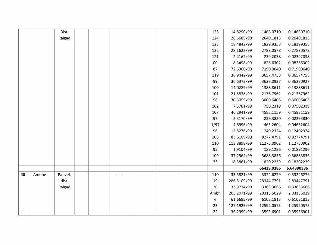
Dist.
Raigad
125
124
123
122
121
00
87
119
99
100
101
98
102
107
97
1/97
96
108
110
95
109
33
14.8290x99
26.6685x99
18.4842x99
28.1622x99
2.4162x99
8.3498x99
72.6360x99
36.9442x99
36.6373x99
14.0289x99
21.5838x99
30.3095x99
7.5781x99
46.2941x99
2.3170x99
4.6996x99
12.5276x99
83.6109x99
113.8898x99
1.9104x99
37.2564x99
18.3861x99
1468.0710
2640.1815
1829.9358
2788.0578
239.2038
826.6302
7190.9640
3657.4758
3627.0927
1388.8611
2136.7962
3000.6405
750.2319
4583.1159
229.3830
465.2604
1240.2324
8277.4791
11275.0902
189.1296
3688.3836
1820.2239
0.14680710
0.26401815
0.18299358
0.27880578
0.02392038
0.08266302
0.71909640
0.36574758
0.36270927
0.13888611
0.21367962
0.30006405
0.07502319
0.45831159
0.02293830
0.04652604
0.12402324
0.82774791
1.12750902
0.01891296
0.36883836
0.18202239
66439.0386 6.64390386
40 Ambhe Panvel,
dist.
Raigad
‐‐‐ 110
19
20
Ambh
e
23
22
33.5821x99
286.3109x99
33.9734x99
205.2071x99
61.6685x99
127.1925x99
36.2999x99
3324.6279
28344.7791
3363.3666
20315.5029
6105.1815
12592.0575
3593.6901
0.33246279
2.83447791
0.33633666
2.03155029
0.61051815
1.25920575
0.35936901

25
26
27
48.7788x99
11.6335x99
4829.1012
1151.7165
0.48291012
0.11517165
83620.0233 8.36200233
41 Morbe Panvel,
dist.
Raigad
Km.
47/201
To
Km.
49/491
167
145
165
168
64
183
182
168
186
186
187
188
172
171
170
00
27/2
204
203
241
205
206
207
00
233
234
111.5388x126
5.6428x126
42.2904x126
386.4250x126
7.1040x126
27.9679x126
58.4297x126
12.9762x126
55.3021x126
101.7537x126
51.5244x126
36.3608x126
136.8136x126
157.2109x126
40.6568x126
1.5998x126
2.9539x126
1.1245x126
165.7756x126
7.2005x126
15.0157x126
142.4456x126
18.1807x126
30.0504x126
75.3633x126
13.8997x126
14053.8888
710.9928
5328.5904
48689.55
895.104
3523.9554
7362.1422
1635.0012
6968.0646
12820.9662
6492.0744
4581.4608
17238.5136
19808.5734
5122.7568
201.5748
372.1914
141.687
20887.7256
907.263
1891.9782
17948.1456
2290.7682
3786.3504
9495.7758
1751.3622
1.40538888
0.07109928
0.53285904
4.868955
0.0895104
0.35239554
0.73621422
0.16350012
0.69680646
1.28209662
0.64920744
0.45814608
1.72385136
1.98085734
0.51227568
0.02015748
0.03721914
0.0141687
2.08877256
0.0907263
0.18919782
1.79481456
0.22907682
0.37863504
0.94957758
0.17513622
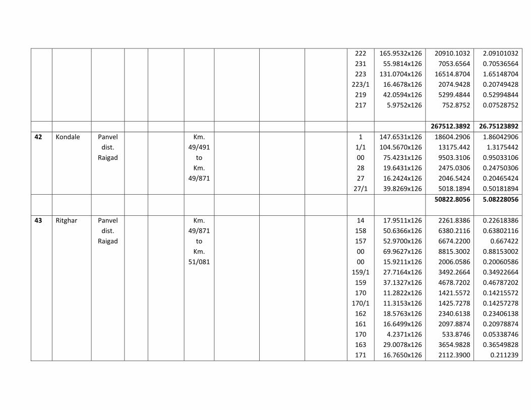
222
231
223
223/1
219
217
165.9532x126
55.9814x126
131.0704x126
16.4678x126
42.0594x126
5.9752x126
20910.1032
7053.6564
16514.8704
2074.9428
5299.4844
752.8752
2.09101032
0.70536564
1.65148704
0.20749428
0.52994844
0.07528752
267512.3892 26.75123892
42 Kondale Panvel
dist.
Raigad
Km.
49/491
to
Km.
49/871
1
1/1
00
28
27
27/1
147.6531x126
104.5670x126
75.4231x126
19.6431x126
16.2424x126
39.8269x126
18604.2906
13175.442
9503.3106
2475.0306
2046.5424
5018.1894
1.86042906
1.3175442
0.95033106
0.24750306
0.20465424
0.50181894
50822.8056 5.08228056
43 Ritghar Panvel
dist.
Raigad
Km.
49/871
to
Km.
51/081
14
158
157
00
00
159/1
159
170
170/1
162
161
170
163
171
17.9511x126
50.6366x126
52.9700x126
69.9627x126
15.9211x126
27.7164x126
37.1327x126
11.2822x126
11.3153x126
18.5763x126
16.6499x126
4.2371x126
29.0078x126
16.7650x126
2261.8386
6380.2116
6674.2200
8815.3002
2006.0586
3492.2664
4678.7202
1421.5572
1425.7278
2340.6138
2097.8874
533.8746
3654.9828
2112.3900
0.22618386
0.63802116
0.667422
0.88153002
0.20060586
0.34922664
0.46787202
0.14215572
0.14257278
0.23406138
0.20978874
0.05338746
0.36549828
0.211239

155
164
154
160
168
167
165
153
166
147
148
149
150
151
146
145
144
142
143
136
137
138/1
138/2
132
135
134
176
117/1
118/1
130
8.6509x126
47.0922x126
10.0461x126
1.4130x126
1.7794x126
18.4542x126
9.2318x126
18.7626x126
12.3822x126
1.0199x126
28.1848x126
42.3183x126
20.3341x126
0.7497x126
0.7097x126
2.7804x126
26.4009x126
1.8990x126
24.4447x126
86.0964x126
24.9077x126
15.8945x126
1.4498x126
1.1093x126
31.2419x126
38.6506x126
10.5579x126
5.4594x126
11.8240x126
2.1169x126
1090.0134
5933.6172
1265.8086
178.038
224.2044
2325.2292
1163.2068
2364.0876
1560.1572
128.5074
3551.2848
5332.1058
2562.0966
94.4622
89.4222
350.3304
3326.5134
239.274
3080.0322
10848.1464
3138.3702
2002.707
182.6748
139.7718
3936.4794
4869.9756
1330.2954
687.8844
1489.824
266.7294
0.10900134
0.59336172
0.12658086
0.0178038
0.02242044
0.23252292
0.11632068
0.23640876
0.15601572
0.01285074
0.35512848
0.53321058
0.25620966
0.00944622
0.00894222
0.03503304
0.33265134
0.0239274
0.30800322
1.08481464
0.31383702
0.2002707
0.01826748
0.01397718
0.39364794
0.48699756
0.13302954
0.06878844
0.1489824
0.02667294

128/2
128/1
129
118/2
118/3
128
00
128
126/1
126
126
127
125
124
10.6741x126
26.9955x126
13.7426x126
4.5256x126
19.9526x126
14.9248x126
33.0636x126
63.5304x126
2.3836x126
8.6399x126
9.0309x126
10.3245x126
28.5743x126
60.9015x126
1344.9366
3401.433
1731.5676
570.2256
2514.0276
1880.5248
4166.0136
8004.8304
300.3336
1088.6274
1137.8934
1300.887
3600.3618
7673.589
0.13449366
0.3401433
0.17315676
0.05702256
0.25140276
0.18805248
0.41660136
0.80048304
0.03003336
0.10886274
0.11378934
0.1300887
0.36003618
0.7673589
150362.1504 15.03621504
44 Usaroli Panvel
dist.
Raigad
Km.
51/081
to
Km.
51/451
5
5/1
4
4/1
4/2
64/1
64/3
64/2
63/1
63/2
63/3
63/4
63/5
118.5533x126
14.3598x126
66.9760x126
26.6213x126
21.2699x126
3.9403x126
39.0013x126
29.4593x126
15.0866x126
23.6080x126
38.6977x126
7.4091x126
4.8134x126
14937.7158
1809.3348
8438.976
3354.2838
2680.0074
496.4778
4914.1638
3711.8718
1900.9116
2974.608
4875.9102
933.5466
606.4884
1.49377158
0.18093348
0.8438976
0.33542838
0.26800074
0.04964778
0.49141638
0.37118718
0.19009116
0.2974608
0.48759102
0.09335466
0.06064884
51634.296 5.1634296

45 Chinchava
li
Panvel
dist.
Raigad
Km.
51/451
to
Km.
51/911
76Pt.
93
92
76P
79
77
140.7097x126
8.5301x126
13.0025x126
100.4317x126
101.7298x126
1.5204x126
17729.4222
1074.7926
1638.3150
12654.3942
12817.9548
191.5704
1.77294222
0.10747926
0.16383150
1.26543942
1.28179548
0.01915704
46106.4492 4.61064492
46 Manghar Panvel
dist.
Raigad
Km.
51/911
to
Km.
52/801
12
11
11/1
15
16
17
10
18
18
1/1
31.3660x126
114.8492x126
1.2517x126
26.7292x126
45.9653x126
22.9387x126
20.8846x126
5.7849x126
59.5488x126
24.0150x126
3952.116
14470.9992
157.7142
3367.8792
5791.6278
2890.2762
2631.4596
9548.8974
7503.1488
3025.89
0.3952116
1.44709992
0.01577142
0.33678792
0.57916278
0.28902762
0.26314596
0.95488974
0.75031488
0.302589
53340.0008 5.33400008
47 Umbroli Panvel
dist.
Raigad
‐‐‐ 71
70
68
66
67
65
21.3183x126
10.5045x126
73.9892x126
136.4907x126
2.1583x126
46.0119x126
2686.1058
1323.5670
9322.6392
17197.8282
271.9458
5797.4994
0.26861058
0.13235670
0.93226392
1.71978282
0.02719458
0.57974994
36599.5854 3.65995854
48 Nere Panvel
dist.
Raigad
Km.
52/801
to
Km.
287
289/1
286
289/2
10.0781x126
9.4377x126
51.0842x126
108.8839x126
1269.8406
1189.1502
6436.6092
13719.3714
0.12698406
0.11891502
0.64366092
1.37193714

54/751 290
289/3
289/4
291
339/1
334
333
89.8590x126
64.8511x126
32.3057x126
13.7407x126
411.4654x126
34.0379x126
10.9352x126
11322.234
8171.2386
4070.5182
1731.3282
51844.6404
4288.7754
1377.8352
1.1322234
0.81712386
0.40705182
0.17313282
5.18446404
0.42887754
0.13778352
105421.5414 10.54215414
49 Ambivali Panvel
Dist.
Raigad
Km.
54/751
to Km.
55/841
50 Sangtoli Panvel
dist.
Raigad
‐‐‐ 16
18
18
9
4
87.6389x126
680.5478x126
355.9206x126
22.8284x126
59.3485x126
11042.5014
85749.0228
44845.9956
2876.3784
7477.9110
1.10425014
8.57490228
4.48459956
0.28763784
0.7477911
151991.8092 15.19918092
51 Moho Panvel
Dist.
Raigad
Km.
55/841
to
Km.
56/431
52 Wangani Panvel
dist.
Raigad
Km.
56/431
to Km.
57/021
31/2
31/5
37/1
37/2
36/1
36/2
36/2
112.4191x126
25.7522x126
22.9122x126
38.9544x126
5.5487x126
75.8338x126
80.3453x126
14164.8066
3244.7772
2886.9372
4908.2544
699.1362
9555.0588
10123.5078
1.41648066
0.32447772
0.28869372
0.49082544
0.06991362
0.95550588
1.01235078
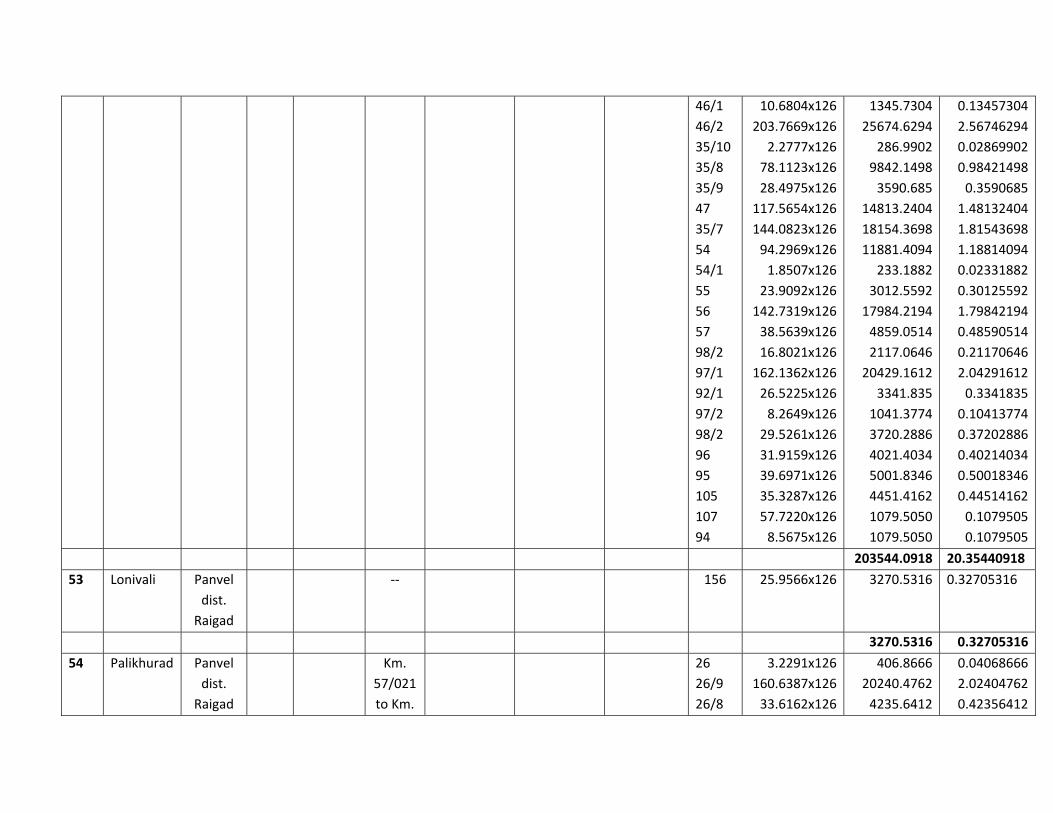
46/1
46/2
35/10
35/8
35/9
47
35/7
54
54/1
55
56
57
98/2
97/1
92/1
97/2
98/2
96
95
105
107
94
10.6804x126
203.7669x126
2.2777x126
78.1123x126
28.4975x126
117.5654x126
144.0823x126
94.2969x126
1.8507x126
23.9092x126
142.7319x126
38.5639x126
16.8021x126
162.1362x126
26.5225x126
8.2649x126
29.5261x126
31.9159x126
39.6971x126
35.3287x126
57.7220x126
8.5675x126
1345.7304
25674.6294
286.9902
9842.1498
3590.685
14813.2404
18154.3698
11881.4094
233.1882
3012.5592
17984.2194
4859.0514
2117.0646
20429.1612
3341.835
1041.3774
3720.2886
4021.4034
5001.8346
4451.4162
1079.5050
1079.5050
0.13457304
2.56746294
0.02869902
0.98421498
0.3590685
1.48132404
1.81543698
1.18814094
0.02331882
0.30125592
1.79842194
0.48590514
0.21170646
2.04291612
0.3341835
0.10413774
0.37202886
0.40214034
0.50018346
0.44514162
0.1079505
0.1079505
203544.0918 20.35440918
53 Lonivali Panvel
dist.
Raigad
‐‐ 156 25.9566x126 3270.5316 0.32705316
3270.5316 0.32705316
54 Palikhurad Panvel
dist.
Raigad
Km.
57/021
to Km.
26
26/9
26/8
3.2291x126
160.6387x126
33.6162x126
406.8666
20240.4762
4235.6412
0.04068666
2.02404762
0.42356412

58/471 26/6
26/7
27/3
2
1/3
29/1
1/4
Gaoth
an
29/3
29/2
32
6
31/2
31/1
31/32
29/5
6
8/1
29/7
10
14
29/8
13
12
10
11
13
100.4538x126
3.6568x126
32.8708x126
2.9886x126
136.7396x126
2.7886x126
27.4727x126
11.2522x126
33.9245x126
19.0551x126
14.5209x126
23.8658x126
25.6112x126
43.3408x126
45.8614x126
26.4477x126
4.6894x126
3.8159x126
7.5120x126
170.4367x126
18.8374x126
61.3652x126
11.4275x126
17.266x126
117.9986x126
17.5802x126
207.7941x126
12657.1788
460.7568
4141.7208
376.5636
17229.1896
351.3636
3461.5602
1417.7772
4274.487
2400.9426
1829.6334
3007.0908
3227.0112
5460.9408
5778.5364
3332.4102
590.8644
480.8034
946.512
21475.0242
2373.5124
7732.0152
1439.865
2175.5160
14867.8236
2215.1052
26182.0566
1.26571788
0.04607568
0.41417208
0.03765636
1.72291896
0.03513636
0.34615602
0.14177772
0.4274487
0.24009426
0.18296334
0.30070908
0.32270112
0.54609408
0.57785364
0.33324102
0.05908644
0.04808034
0.0946512
2.14750242
0.23735124
0.77320152
0.1439865
0.2175516
1.48678236
0.22151052
2.61820566
174769.245 17.4769245
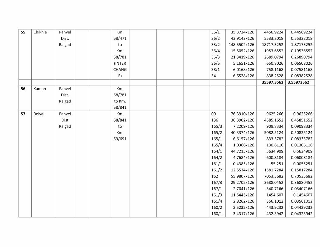
55 Chikhle Panvel
Dist.
Raigad
Km.
58/471
to
Km.
58/781
(INTER
CHANG
E)
36/1
36/2
33/2
36/4
36/3
36/5
38/1
34
35.3724x126
43.9143x126
148.5502x126
15.5052x126
21.3419x126
5.1651x126
6.0168x126
6.6528x126
4456.9224
5533.2018
18717.3252
1953.6552
2689.0794
650.8026
758.1168
838.2528
0.44569224
0.55332018
1.87173252
0.19536552
0.26890794
0.06508026
0.07581168
0.08382528
35597.3562 3.55973562
56 Kaman Panvel
Dist.
Raigad
Km.
58/781
to Km.
58/841
57 Belvali Panvel
Dist
Raigad
Km.
58/841
to
Km.
59/691
00
136
165/3
165/2
165/1
165/4
164/1
164/2
161/1
161/2
162
167/3
167/1
161/3
161/4
160/2
160/1
76.3910x126
36.3902x126
7.2209x126
40.3374x126
6.6157x126
1.0366x126
44.7215x126
4.7684x126
0.4385x126
12.5534x126
55.9807x126
29.2702x126
2.7041x126
11.5445x126
2.8262x126
3.5232x126
3.4317x126
9625.266
4585.1652
909.8334
5082.5124
833.5782
130.6116
5634.909
600.8184
55.251
1581.7284
7053.5682
3688.0452
340.7166
1454.607
356.1012
443.9232
432.3942
0.9625266
0.45851652
0.09098334
0.50825124
0.08335782
0.01306116
0.5634909
0.06008184
0.0055251
0.15817284
0.70535682
0.36880452
0.03407166
0.1454607
0.03561012
0.04439232
0.04323942
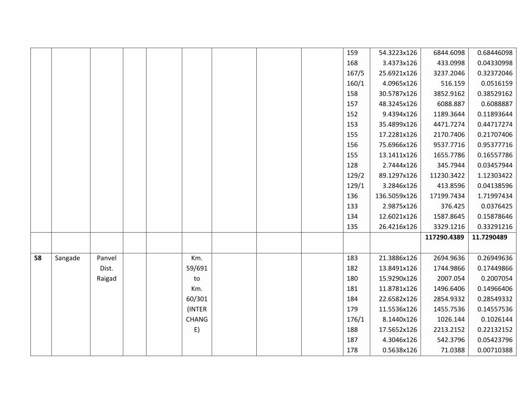
159
168
167/5
160/1
158
157
152
153
155
156
155
128
129/2
129/1
136
133
134
135
54.3223x126
3.4373x126
25.6921x126
4.0965x126
30.5787x126
48.3245x126
9.4394x126
35.4899x126
17.2281x126
75.6966x126
13.1411x126
2.7444x126
89.1297x126
3.2846x126
136.5059x126
2.9875x126
12.6021x126
26.4216x126
6844.6098
433.0998
3237.2046
516.159
3852.9162
6088.887
1189.3644
4471.7274
2170.7406
9537.7716
1655.7786
345.7944
11230.3422
413.8596
17199.7434
376.425
1587.8645
3329.1216
0.68446098
0.04330998
0.32372046
0.0516159
0.38529162
0.6088887
0.11893644
0.44717274
0.21707406
0.95377716
0.16557786
0.03457944
1.12303422
0.04138596
1.71997434
0.0376425
0.15878646
0.33291216
117290.4389
11.7290489
58 Sangade Panvel
Dist.
Raigad
Km.
59/691
to
Km.
60/301
(INTER
CHANG
E)
183
182
180
181
184
179
176/1
188
187
178
21.3886x126
13.8491x126
15.9290x126
11.8781x126
22.6582x126
11.5536x126
8.1440x126
17.5652x126
4.3046x126
0.5638x126
2694.9636
1744.9866
2007.054
1496.6406
2854.9332
1455.7536
1026.144
2213.2152
542.3796
71.0388
0.26949636
0.17449866
0.2007054
0.14966406
0.28549332
0.14557536
0.1026144
0.22132152
0.05423796
0.00710388

176/2
189
175
177
173
174
190
Gaoth
an
171
172
116
117
115
108/1
108/2
114
114/1
113/2
113/1
113
113
111
21.2851x126
19.7001x126
28.0690x126
2.6579x126
47.2352x126
20.1544x126
1.1450x126
23.6003x126
18.3943x126
14.6680x126
10.4723x126
25.1185x126
64.6881x126
1.8116x126
2.5092x126
17.8365x126
27.7176x126
15.4258x126
5.7023x126
6.8058x126
40.0176x126
30.9074x126
2681.9226
2482.2126
3536.694
334.8954
5951.6352
2539.4544
144.27
2973.6378
2317.6818
1848.168
1319.5098
3164.931
8150.7006
228.2616
316.1592
2247.399
3492.4176
1943.6508
718.4898
857.5308
5042.2176
3894.3324
0.26819226
0.24822126
0.3536694
.03348954
0.59516352
0.25394544
0.014427
0.29736378
0.23176818
0.1848168
0.13195098
0.3164931
0.81507006
0.02282616
0.03161592
0.2247399
0.34924176
0.19436508
0.07184898
0.08575308
0.50422176
0.38943324
59837.06 5.983706
59 Borle Panvel
Dist.
Raigad
Km.
60/301
to
Km.
61/141
156
157/6
169
157/6
167
168
2.7364x126
123.0616x126
22.3755x126
1.6415x126
37.9225x126
7.9005x126
297.864
1550.57616
2819.313
206.829
4778.235
995.463
0.0297864
0.155057616
0.2819313
0.0206829
0.4778235
0.0995463
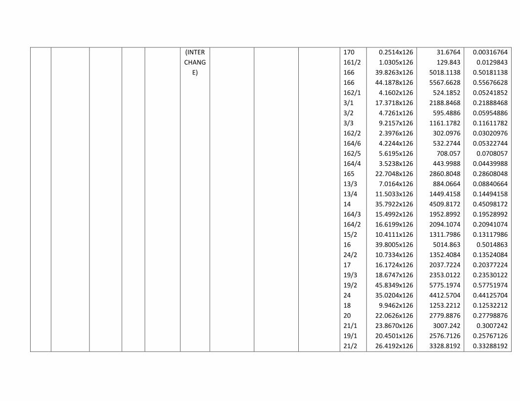
(INTER
CHANG
E)
170
161/2
166
166
162/1
3/1
3/2
3/3
162/2
164/6
162/5
164/4
165
13/3
13/4
14
164/3
164/2
15/2
16
24/2
17
19/3
19/2
24
18
20
21/1
19/1
21/2
0.2514x126
1.0305x126
39.8263x126
44.1878x126
4.1602x126
17.3718x126
4.7261x126
9.2157x126
2.3976x126
4.2244x126
5.6195x126
3.5238x126
22.7048x126
7.0164x126
11.5033x126
35.7922x126
15.4992x126
16.6199x126
10.4111x126
39.8005x126
10.7334x126
16.1724x126
18.6747x126
45.8349x126
35.0204x126
9.9462x126
22.0626x126
23.8670x126
20.4501x126
26.4192x126
31.6764
129.843
5018.1138
5567.6628
524.1852
2188.8468
595.4886
1161.1782
302.0976
532.2744
708.057
443.9988
2860.8048
884.0664
1449.4158
4509.8172
1952.8992
2094.1074
1311.7986
5014.863
1352.4084
2037.7224
2353.0122
5775.1974
4412.5704
1253.2212
2779.8876
3007.242
2576.7126
3328.8192
0.00316764
0.0129843
0.50181138
0.55676628
0.05241852
0.21888468
0.05954886
0.11611782
0.03020976
0.05322744
0.0708057
0.04439988
0.28608048
0.08840664
0.14494158
0.45098172
0.19528992
0.20941074
0.13117986
0.5014863
0.13524084
0.20377224
0.23530122
0.57751974
0.44125704
0.12532212
0.27798876
0.3007242
0.25767126
0.33288192

21/3
22
23
24.8712x126
4.8582x126
51.9251x126
3133.7712
612.1332
6542.5626
0.31337712
0.06121332
0.65425626
87094.74 8.709474
60 Arivali Panvel
Dist.
Raigad
Km.
61/141
to Km.
61/701
61 Kon Panvel
dist.
Raigad
Km.
61/701
to
Km.
62/651
(INTER
CHANG
E)
50
51
72
73/2F
73/1F
73A
62
66
61
60
59
99
98
66
67
69
95
96
20.9825x126
150.6715x126
17.5747x126
15.7411x126
75.8185x126
13.6906x126
82.4180x126
26.6118x126
29.2991x126
119.7097x126
9.2528x126
46.1129x126
56.4589x126
105.7710x126
8.1228x126
23.9979x126
136.1956x126
26.1864x126
2643.795
18984.609
2214.4122
1983.3786
9553.131
1725.0156
10384.668
3353.0868
3691.6866
15083.4222
1165.8528
5810.2254
677.5068
13327.146
1023.4728
3023.7354
17160.6456
3299.4864
0.2643795
1.8984609
0.22144122
0.19833786
0.9553131
0.17250156
1.0384668
0.33530868
0.36916866
1.50834222
0.11658528
0.58102254
0.06775068
1.3327146
0.10234728
0.30237354
1.71606456
0.32994864
115105.276 11.5105276

62 Dervali Panvel
dist.
Raigad
Km.
62/651
to
Km.
63/091
78
79/2
80
96
97/2
29P
98
99
100/2
57
Derval
i
18.3496x126
63.7882x126
33.8512x126
68.7003x126
6.7305x126
24.9643x126
2.2960x126
4.3450x126
0.6709x126
7.7761x126
89.2865x126
2312.0496
8037.3132
4265.2512
8656.2378
848.043
3145.5018
289.296
547.47
84.5334
979.7886
11250.099
0.23120496
0.80373132
0.42652512
0.86562378
0.0848043
0.31455018
0.0289296
0.054747
0.00845334
0.09797886
1.1250099
40415.5836 4.04155836
63 Palspe Panvel
dist.
Raigad
Km.
63/091
to
Km.
64/691
58
93
81
79/1
48
59
56
55
54
53
64
65
63
66
63
67
52
131.8763x126
54.4001x126
17.5766x126
24.3499x126
4.0640x126
71.4827x126
25.2530x126
155.3961x126
2.1605x126
57.0080x126
66.4028x126
139.2012x126
7.8296x126
47.5543x126
11.2883x126
50.6904x126
2.0879x126
16616.4138
6854.4126
2214.6516
3068.0874
512.064
9006.8202
3181.878
19579.9086
272.223
7183.008
8366.7528
17539.3512
986.5296
5991.8418
1422.3258
6386.9904
263.0754
1.66164138
0.68544126
0.22146516
0.30680874
0.0512064
0.90068202
0.3181878
1.95799086
0.0272223
0.7183008
0.83667528
1.75393512
0.09865296
0.59918418
0.14223258
0.63869904
0.02630754

67
68
69
70
91
123A
123B
122
92
102
103
109
106
109
107
108
106
69.5871x126
90.8378x126
10.3907x126
0.8562x126
13.6409x126
13.9156x126
41.2672x126
44.4435x126
13.8639x126
43.9922x126
7.6184x126
34.4157x126
84.3555x126
38.8197x126
49.6901x126
57.9447x126
11.2640x126
8767.9746
11445.5628
1309.2282
107.8812
1718.7534
1753.3656
5199.6672
5599.881
1746.8514
5543.0172
959.9184
4336.3782
10628.793
4891.2822
6260.9526
7301.0322
1419.264
0.87679746
1.14455628
0.13092282
0.01078812
0.17187534
0.17533656
0.51996672
0.5599881
0.17468514
0.55430172
0.09599184
0.43363782
1.0628793
0.48912822
0.62609526
0.73010322
0.1419264
188436.1374 18.84361374
64 Kudao Panvel
dist.
Raigad
Km.
64/691
to
Km.
65/461
28/7
28/8
22/1
22/2
31/6
31/3
31/1
31/2
30/1
29/1
29/6
29/2
21.5217x126
10.7930x126
41.1613x126
2.2978x126
3.1883x126
12.4152x126
28.0015x126
0.8085x126
30.9786x126
9.2147x126
11.0577x126
1.3720x126
2711.7342
1359.9180
5186.3238
289.5228
401.7258
1564.3152
3528.189
101.871
3903.3036
1161.0522
1393.2702
172.872
0.27117342
0.1359918
0.51863238
0.02895228
0.04017258
0.15643152
0.3528189
0.0101871
0.39033036
0.11610522
0.13932702
0.0172872

29/5
29/4
29/3
30/2
24/5
41/4
41/5
41/6
30/2
38/3
38/2
38/1
41/3
40/2
40/4
40/5
40/3
40/1
45/6
45/4
45/5
45/2
46/3
46/5
46/7
47/4
47/2
47/1
46/1
48/4
27.6865x126
18.4488x126
13.2674x126
2.9933x126
2.9242x126
0.7990x126
9.1344x126
32.3228x126
2.9933x126
1.3979x126
1.6901x126
11.5527x126
39.1134x126
5.6424x126
9.0417x126
1.7216x126
8.4909x126
16.2455x126
0.9972x126
4.6614x126
11.0013x126
16.4789x126
22.2648x126
22.0602x126
25.1548x126
3.7967x126
10.4024x126
24.3036x126
40.4027x126
33.4464x126
3488.499
2324.5488
1671.6924
377.1558
368.4492
100.674
1150.9344
4072.6728
377.1558
176.1354
201.726
1455.6402
4928.2884
710.9424
1139.2542
216.9216
1069.8534
2046.933
125.6472
587.3364
1386.1638
2076.3414
2805.3648
2779.5852
3169.5048
478.3842
1310.7024
3062.2536
5090.7402
4214.2464
0.3488499
0.23245488
0.16716924
0.03771558
0.03684492
0.0100674
0.11509344
0.40726728
0.03771558
0.01761354
0.0201726
0.14556402
0.49282884
0.07109424
0.1139254
0.02169216
0.10698534
0.2046933
0.01256472
0.05873364
0.13861638
0.20763414
0.28053648
0.27795852
0.31695048
0.04783842
0.13107024
0.30622536
0.50907402
0.42142464
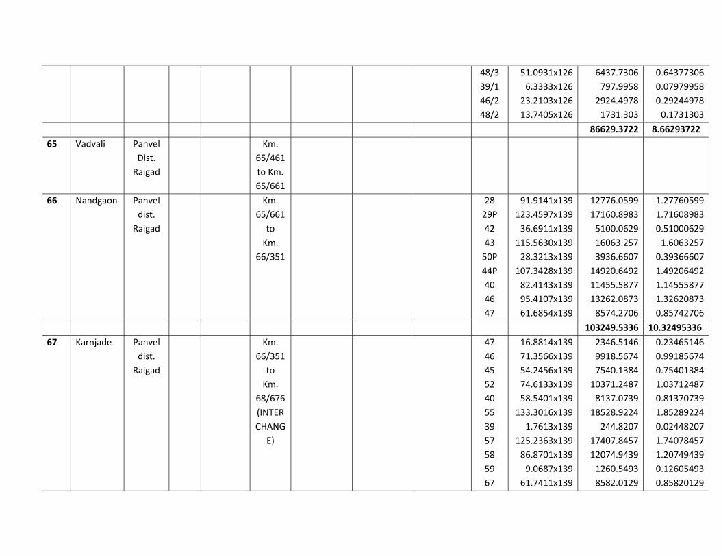
48/3
39/1
46/2
48/2
51.0931x126
6.3333x126
23.2103x126
13.7405x126
6437.7306
797.9958
2924.4978
1731.303
0.64377306
0.07979958
0.29244978
0.1731303
86629.3722 8.66293722
65 Vadvali Panvel
Dist.
Raigad
Km.
65/461
to Km.
65/661
66 Nandgaon Panvel
dist.
Raigad
Km.
65/661
to
Km.
66/351
28
29P
42
43
50P
44P
40
46
47
91.9141x139
123.4597x139
36.6911x139
115.5630x139
28.3213x139
107.3428x139
82.4143x139
95.4107x139
61.6854x139
12776.0599
17160.8983
5100.0629
16063.257
3936.6607
14920.6492
11455.5877
13262.0873
8574.2706
1.27760599
1.71608983
0.51000629
1.6063257
0.39366607
1.49206492
1.14555877
1.32620873
0.85742706
103249.5336 10.32495336
67 Karnjade Panvel
dist.
Raigad
Km.
66/351
to
Km.
68/676
(INTER
CHANG
E)
47
46
45
52
40
55
39
57
58
59
67
16.8814x139
71.3566x139
54.2456x139
74.6133x139
58.5401x139
133.3016x139
1.7613x139
125.2363x139
86.8701x139
9.0687x139
61.7411x139
2346.5146
9918.5674
7540.1384
10371.2487
8137.0739
18528.9224
244.8207
17407.8457
12074.9439
1260.5493
8582.0129
0.23465146
0.99185674
0.75401384
1.03712487
0.81370739
1.85289224
0.02448207
1.74078457
1.20749439
0.12605493
0.85820129
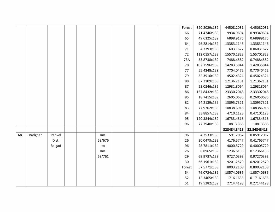
Forest
66
65
64
71
72
73A
78
77
79
88
87
86
85
82
83
84
95
96
320.2029x139
71.4746x139
49.6325x139
96.2814x139
4.3393x139
112.0157x139
53.8738x139
102.7596x139
55.4248x139
32.3916x139
87.3109x139
93.0346x139
167.8432x139
18.7415x139
94.2139x139
77.9762x139
33.8857x139
120.3844x139
77.7940x139
44508.2031
9934.9694
6898.9175
13383.1146
603.1627
15570.1823
7488.4582
14283.5844
7704.0472
4502.4324
12136.2151
12931.8094
23330.2048
2605.0685
13095.7321
10838.6918
4710.1123
16733.4316
10813.366
4.45082031
0.99349694
0.68989175
1.33831146
0.06031627
1.55701823
0.74884582
1.42835844
0.77040472
0.45024324
1.21362151
1.29318094
2.33302048
0.26050685
1.30957321
1.08386918
0.47101123
1.67334316
1.0813366
328484.3413 32.84843413
68 Vadghar Panvel
Dist.
Raigad
Km.
68/676
to
Km.
69/761
96
26
96
26
29
30
Forest
54
52
51
4.2533x139
30.0473x139
28.7811x139
8.8965x139
69.9787x139
66.1961x139
57.5771x139
76.0724x139
12.3465x139
19.5282x139
591.2087
4176.5747
4000.5729
1236.6135
9727.0393
9201.2579
8003.2169
10574.0636
1716.1635
2714.4198
0.05912087
0.41765747
0.40005729
0.12366135
0.97270393
0.92012579
0.80032169
1.05740636
0.17161635
0.27144198

53
60
59
61
57
57
Forest
59.5241x139
5.1228x139
153.8104x139
23.9970x139
116.4870x139
154.8334x139
137.4552x139
8273.8499
712.0692
21379.6456
3335.583
16191.693
21521.8426
19106.2728
0.82738499
0.07120692
2.13796456
0.3335583
1.6191693
2.15218426
1.91062728
142462.0869 14.2462087
69 Kopar Panvel
Dist.
Raigad
63 63.1443x
139
Km.
69/761
to Km.
69/826
8777.0577 0.8777057
7
61
62
57
8.8665x139
11.5171x139
2.1482x139
1232.4435
1600.8769
298.5998
0.12324435
0.16008769
0.02985998
8777.0577 0.8777057
7
3131.9202 0.31319202
70 Pargaon Panvel
Dist.
Raigad
Km.
69/826
to
Km.
70/436
33 252.2233x139 35059.0387 3.50590387
35059.0387 3.50590387
71 Dapoli Panvel
dist.
Raigad
Km.
70/436
to
Km.
72/176
NA
NA
103
101
28/2
NA
23/4
23/1
23/3
23/2
155.4881x139
176.3009x139
1.4547x139
48.8656x139
8.1289x139
40.8662x139
16.4901x139
2.0082x139
12.7239x139
19.2936x139
21612.8459
24505.8251
202.2033
6792.3184
1129.9171
5680.4018
2292.1239
279.1398
1768.6221
2681.8104
2.16128459
2.45058251
0.02022033
0.67923184
0.11299171
0.56804018
0.22921239
0.02791398
0.17686221
0.26818104

23/1
28/1
24/6
28/3
24/7
24/3
24/2
24/4
24/5
25/1
18/6
18/3
18/5
18/7
18/4
17/2
17/3
17/1
18/2
16/5
16/6
16/4
17/4
16/3
16/7
3.4692x139
19.7992x139
16.8692x139
7.4546x139
8.8825x139
9.7427x139
7.804x139
8.3231x139
28.7909x139
7.1993x139
10.2024x139
1.1804x139
20.7699x139
16.0263x139
19.4403x139
15.0340x139
16.6311x139
48.5356x139
14.3182x139
13.0838x139
29.7308x139
21.4310x139
0.5419x139
5.3255x139
7.3935x139
482.2188
2752.0888
2344.8188
1036.1894
1234.6675
1354.2353
1084.756
1156.9109
4001.9351
1000.7027
1418.1336
164.0756
2887.0161
2227.6557
2702.2017
2089.726
2311.7229
6746.4484
1990.2298
1818.6482
4132.5812
2978.909
75.3241
740.2445
1027.6965
0.04822188
0.27520888
0.23448188
0.10361894
0.12346675
0.13542353
0.1084756
0.11569109
0.40019351
0.10007027
0.14181336
0.01640756
0.28870161
0.22276557
0.27022017
0.2089726
0.23117229
0.67464484
0.19902298
0.18186482
0.41325812
0.2978909
0.00753241
0.07402445
0.10276965
72 Manghar Panvel
Dist.
Raigad
Km.
72/176
to Km.
72/636

73 Kunde‐
Wahal
Panvel
Dist.
Raigad
Km.
72/636
to Km.
73/801
74 Babavi Panvel
Dist.
Raigad
Km.
73/801
to Km.
74/291
75 Pande
ghar
Panvel
Dist.
Raigad
Km.
74/291
to Km.
74/901
76 Wahal Panvel
Dist.
Raigad
Km.
74/901
to Km.
76/151
77 Chirle Uran
Dist.
Raigad
Km.
76/151
to KM.
80/001
84982.5162
qmt.
666252.254
5Sqmt.
75.123477
07
Ha.
5086368420
Sqmt.
508.6368420
1 Ha.
Total
Total Forest area identified under proposed multimodal corridor =75.12347707 Ha

1 | P a g e
Compliance Report of the 141st Meeting of the Expert Appraisal Committee for Building/ Construction
Projects/ Township and Area Development Projects, Coastal Regulation Zone, Infrastructure Development
and Miscellaneous Projects held on 26th &28th November, 2014 at MOEF&CC, New Delhi.
Development of Multi model Corridor from Navghar to Chirner (Near JNPT) in the State of
Maharashtra by M/s Mumbai Metropolitan Regional Development Authority (F. No. 10-25/2014-IA.III)
Sl. No. Additional TOR for further
study Comply Remarks
(i)
Justification for selecting the alignment along with the various alternatives considered, procedures and criteria adopted for selection of final alternative reasons.
Refer Chapter-5 Refer Chapter-5
(ii)
Submit detailed alignment plan, with details such as nature of terrain (plain, rolling, hilly), land use pattern, habitation, cropping pattern, forest area, environmentally sensitive places, mangroves, notified industrial areas, sand dunes, sea, river, lake, details of villages, tehsils, districts and states, latitude and longitude for important locations falling on the alignment by employing remote sensing techniques followed by ground truthing and also through secondary data sources.
Terrain: Terrain along the project is plain terrain except for few stretches can be classified as rolling. Land use: The predominantly land use along the project road is agriculture followed by settlements, barren and waste land, creeks, river, road, railways line. Forest Area: Forest proposal preparation is under progress Environmentally Sensitive Places: National Park: MMC alignment is traversing through the Sanjay Gandhi National Park and will divert 14.4ha. land of NP. Wildlife Sanctuary: Tungareshwar Wildlife Sanctuary, Thane located 153.0m away from the MMC alignment Bird Sanctuary : Karnala Bird Sanctuary, Panvel located 5813m away from the MMC alignment Eco-sensitive Zone : proposed alignment of MMC is passing 105 m away from the boundary of Matheran Eco-sensitive zone Notified Critically Polluted Industrial Area: Two critically polluted industrial area notified by CPCB are located within the 10km radius of the alignment of the proposed MMC. The CPI area are Domviwili (MIDC Phase I&II) and Navi Mumbai TCC industrial area, Kalwa and
Refer section 3.3.4 of Chapter-3 of EIA report Refer section 3.3.4 of Chapter-3 of EIA report
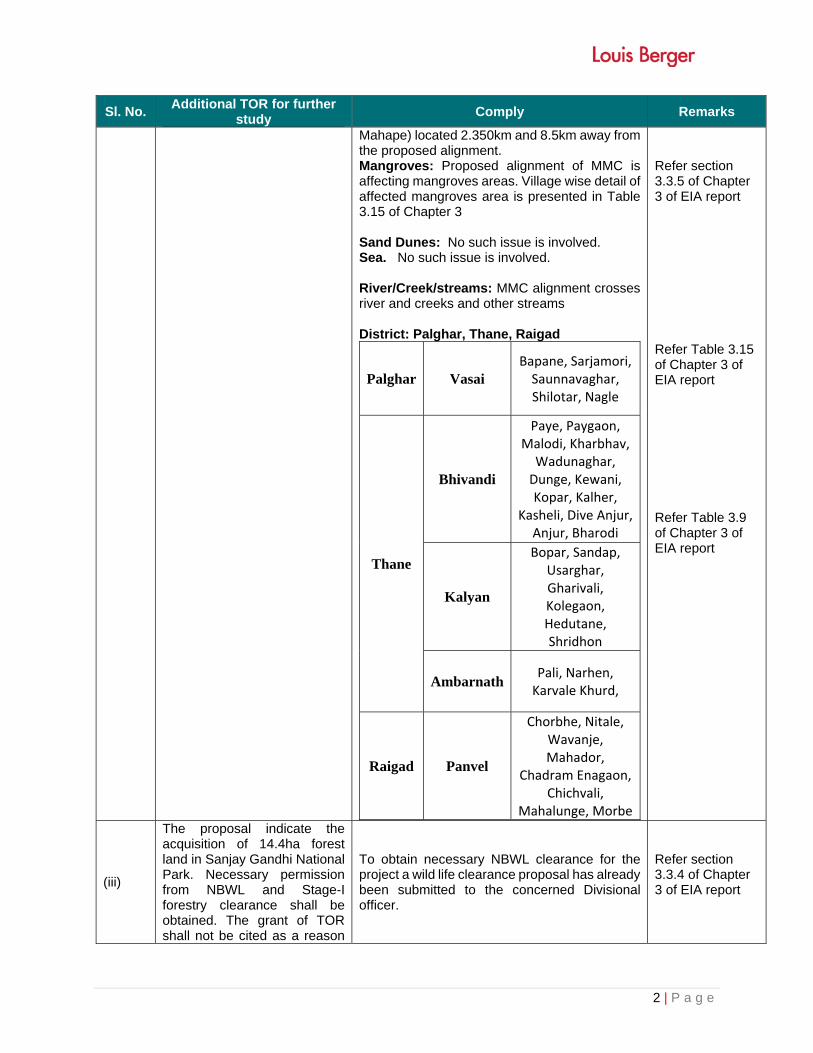
2 | P a g e
Sl. No. Additional TOR for further
study Comply Remarks
Mahape) located 2.350km and 8.5km away from the proposed alignment. Mangroves: Proposed alignment of MMC is affecting mangroves areas. Village wise detail of affected mangroves area is presented in Table 3.15 of Chapter 3 Sand Dunes: No such issue is involved. Sea. No such issue is involved. River/Creek/streams: MMC alignment crosses river and creeks and other streams District: Palghar, Thane, Raigad
Palghar Vasai Bapane, Sarjamori, Saunnavaghar, Shilotar, Nagle
Thane
Bhivandi
Paye, Paygaon, Malodi, Kharbhav, Wadunaghar, Dunge, Kewani, Kopar, Kalher,
Kasheli, Dive Anjur, Anjur, Bharodi
Kalyan
Bopar, Sandap, Usarghar, Gharivali, Kolegaon, Hedutane, Shridhon
AmbarnathPali, Narhen, Karvale Khurd,
Raigad Panvel
Chorbhe, Nitale, Wavanje, Mahador,
Chadram Enagaon, Chichvali,
Mahalunge, Morbe
Refer section 3.3.5 of Chapter 3 of EIA report
Refer Table 3.15 of Chapter 3 of EIA report Refer Table 3.9 of Chapter 3 of EIA report
(iii)
The proposal indicate the acquisition of 14.4ha forest land in Sanjay Gandhi National Park. Necessary permission from NBWL and Stage-I forestry clearance shall be obtained. The grant of TOR shall not be cited as a reason
To obtain necessary NBWL clearance for the project a wild life clearance proposal has already been submitted to the concerned Divisional officer.
Refer section 3.3.4 of Chapter 3 of EIA report
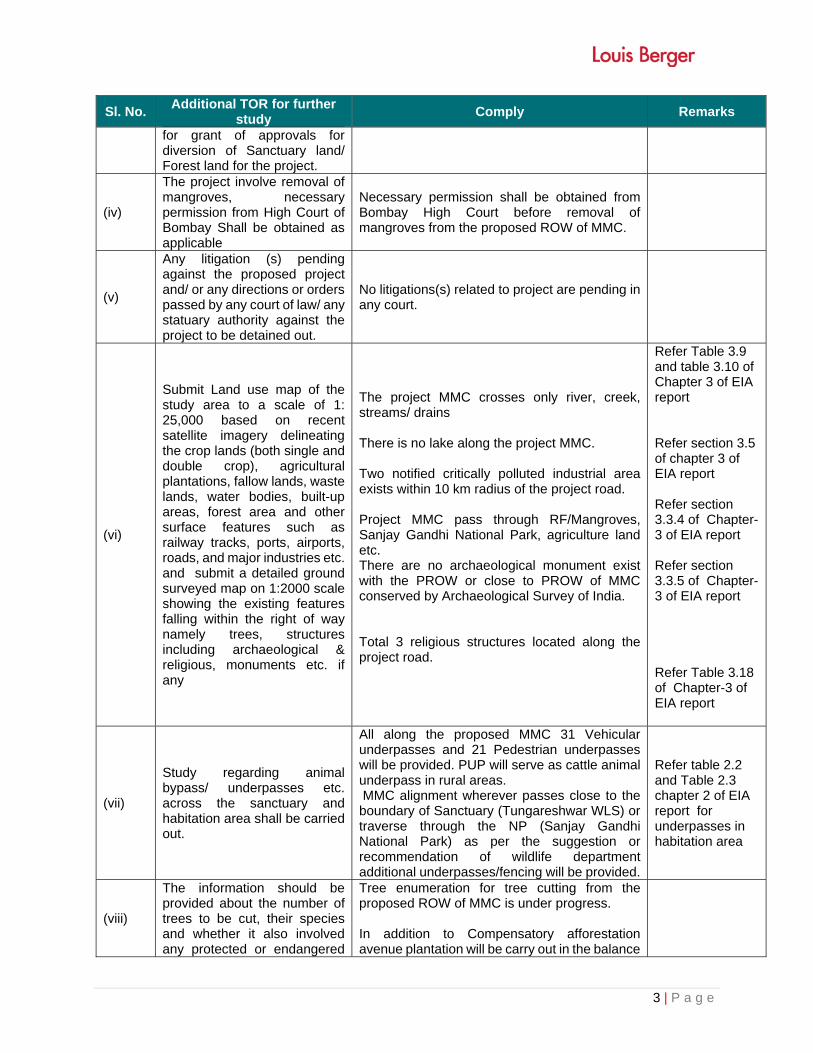
3 | P a g e
Sl. No. Additional TOR for further
study Comply Remarks
for grant of approvals for diversion of Sanctuary land/ Forest land for the project.
(iv)
The project involve removal of mangroves, necessary permission from High Court of Bombay Shall be obtained as applicable
Necessary permission shall be obtained from Bombay High Court before removal of mangroves from the proposed ROW of MMC.
(v)
Any litigation (s) pending against the proposed project and/ or any directions or orders passed by any court of law/ any statuary authority against the project to be detained out.
No litigations(s) related to project are pending in any court.
(vi)
Submit Land use map of the study area to a scale of 1: 25,000 based on recent satellite imagery delineating the crop lands (both single and double crop), agricultural plantations, fallow lands, waste lands, water bodies, built-up areas, forest area and other surface features such as railway tracks, ports, airports, roads, and major industries etc. and submit a detailed ground surveyed map on 1:2000 scale showing the existing features falling within the right of way namely trees, structures including archaeological & religious, monuments etc. if any
The project MMC crosses only river, creek, streams/ drains There is no lake along the project MMC. Two notified critically polluted industrial area exists within 10 km radius of the project road. Project MMC pass through RF/Mangroves, Sanjay Gandhi National Park, agriculture land etc. There are no archaeological monument exist with the PROW or close to PROW of MMC conserved by Archaeological Survey of India. Total 3 religious structures located along the project road.
Refer Table 3.9 and table 3.10 of Chapter 3 of EIA report Refer section 3.5 of chapter 3 of EIA report Refer section 3.3.4 of Chapter-3 of EIA report Refer section 3.3.5 of Chapter-3 of EIA report Refer Table 3.18 of Chapter-3 of EIA report
(vii)
Study regarding animal bypass/ underpasses etc. across the sanctuary and habitation area shall be carried out.
All along the proposed MMC 31 Vehicular underpasses and 21 Pedestrian underpasses will be provided. PUP will serve as cattle animal underpass in rural areas. MMC alignment wherever passes close to the boundary of Sanctuary (Tungareshwar WLS) or traverse through the NP (Sanjay Gandhi National Park) as per the suggestion or recommendation of wildlife department additional underpasses/fencing will be provided.
Refer table 2.2 and Table 2.3 chapter 2 of EIA report for underpasses in habitation area
(viii)
The information should be provided about the number of trees to be cut, their species and whether it also involved any protected or endangered
Tree enumeration for tree cutting from the proposed ROW of MMC is under progress. In addition to Compensatory afforestation avenue plantation will be carry out in the balance

4 | P a g e
Sl. No. Additional TOR for further
study Comply Remarks
species, Necessary green belt shall be provided on both side of the highways with proper central verge and cost provision should be made for regular maintenance.
ROW of the MMC. Budget for the avenue plantation is incorporated in environmental budget
Refer table 9.1 of Chapter of EIA report
(ix)
If proposed route is passing through a city or town, with houses and human habitation on either side of the road, the necessity for provision of bypass/ diversion/ underpass/ underpasses shall be examined and submitted. The proposal should also indicate the location of wayside amenities, which should include petrol station/ service centre, rest areas including public conveyance etc.
Proposed route MMC is new alignment in agriculture land. Fly over, vehicular under passes and Pedestrian underpasses will be provided. Other amenities such as petroleum, rest area etc will be provided
Refer Table 2.2 and Table 2.3 and Table 2.5 of chapter 2 of EIA report Refed in DPR
(x)
Submit the details about measure taken for the pedestrian safety and construction of underpasses and foot over bridge along with flyovers and interchanges.
Provided in EMP
Refer Table 2.2 and Table 2.3 and Table 2.5 of chapter 2/10 of EIA report
(xi)
Examine and submit the details of use of fly ash in the road construction, if the project road is located within the 100 km from the Thermal Power Plant.
There are two thermal power plant located within the 100km radius from the alignment viz. (a) Tata Thermal Power Plant, Trombay, Mumbai about 30km away from the project alignment and(b) Dahanu Thermal Power Station, Dahanu, Thane- 70km away from the project alignment.
Refer section 3.3.4 of Chapter 3 of EIA report
(xii) Examine and submit the details of sand quarry, borrow area and rehabilitation
Refer Table 3.17 of Chapter 3 and section 4.2.4.4 of chapter 4 of EIA report.
(xiii)
The air quality monitoring should be carried out as per the new notification issued on 16th November, 2009.
AAQ monitored as per notification issued on 16.11.2009
Refer Table 3.5 of Chapter 3 of EIA report
(xiv)
Identify project activities during construction and operation phases, which will affect the noise levels and the potential for increased noise resulting from this project. Discuss the effect of noise levels on near by habitation during the construction and operational phases of the
The project construction activities will involve clearing and grubbing, trees cutting, site development works, road and rail construction, construction of bridges, way side facilities, etc. The project actives proposed during construction phase are presented in Chapter 2 of EIA Report. The construction activities will have adverse impacts on the environment. Identification and
Refer f Chapter 2 and Chapter 4 of EIA report

5 | P a g e
Sl. No. Additional TOR for further
study Comply Remarks
proposed highway. Identify noise reduction measures and traffic management strategies to be deployed for reducing the negative impact if any. Prediction of noise levels should be done by using mathematical modelling at different representative locations.
assessment of anticipated environmental impacts have been carried out and presented in Chapter 4.
(xv)
Examine the impact during construction activities due to generation of fugitive dust from crusher units, air emissions from hot mix plants and vehicles used for transportation of materials and prediction of impact on ambient air quality using appropriate mathematical model, description of model, input requirement and reference of derivation, distribution of major pollutants and presentation in tabular form for easy interpretation shall be carried out.
The impact of the project road during the construction phase due to generation of dust emissions, air emissions from hot mix plants and vehicles used for transportation of materials are anticipated during construction phase. Prediction of impact on ambient air quality by CALINE - 4 mathematical model, using CPCB emission factors has been be carried out and presented in Chapter 4. • Hot mix plant will have in-built provision of
pollution control equipment. • Hot mix plants will be installed in down wind
direction minimum 1 km away from any populated area.
• Hot mix plant will be installed with “Consent to Establish” and operated with “Consent to Operate” of State Pollution Control Boards.
• All construction equipment and vehicles will be operated with pollution under control certificate.
• Regular maintenance of vehicles and construction equipment’s,
• Water sprinkling will be carried out to control fugitive dust emission.
Regular monitoring of ambient air quality will be carried during construction and operation phase.
(xvi)
Also examine and submit the details about the protection to existing habitations from dust, noise, odour etc. during construction stage
During construction and operation phases, following mitigation measures will be adopted to minimise impacts from dust, noise and odour : • Sprinkling of water to suppress dust • Maintenance of vehicles and construction
equipment’s. • Use of silencers and mufflers, • Construction activities only during day time. • Collection of debris and waste and deposal as
per standards practices. Use of applicable IRC guidelines
Refer Chapter-4 of EIA report
(xvii) If the proposed route involves cutting of earth, the details of area to be cut, depth of cut,
Minor earth cutting will required in rolling terrain and cut material will be utilised for felling of embankment.
Chapter 10/4

6 | P a g e
Sl. No. Additional TOR for further
study Comply Remarks
locations, soil type, volume and quantity of earth and other materials to be removed with location of disposal/ dump site along with necessary permission
(xviii)
If the proposed route is passing through low lying areas, details of fill materials and initial and final levels after filling above MSL, should be examined and submit.
Yes, In maximum portion of the low lying areas fly overs are proposed. And at few locations embankment height of the MMC alignment will be 2-3 m from the MSL. Fly ash and soil will be used for this.
Refer Table 2.5 of Chapter 2 of chapter 2.
(xix)
Examine and submit the water bodies including the seasonal ones within the corridor of impacts along with their status, volumetric capacity and quality likely impacts on them due to the project
Project road crosses river, creek and small streams and drains. Major or minor bridges will be constructed over these water bodies. Following mitigation measures will be taken to avoid the impact on water bodies during construction of MMC: Construction camps, if any, shall be
properly located to avoid contamination of surface water bodies by the generated waste and waste water.
Good engineering practices to be followed to avoid the clogging of water channels along the project road.
Coffer dam will be constructed to minimise the impact on water quality.
No waste will be dumped in the water bodies
Refer subsection 3.3.3 of chapter-3 and section 4.2.6 of chapter 4 of the EIA report
(xx)
Examine and submit details of water quantity required and source of water including water requirement during the construction stage with supporting data and also classification of ground water based on the CGWA classification
About 250KLD water will be required for construction of the project for 3 years. Water for road construction will be taken from surface water bodies and partly from ground water resources. Public water sources and supply will not be used for road construction.
Refer section 4.1.5 of chapter 4.
(xxi)
Examine and submit the details of measures taken during constructions of bridges across river/canal/major or minor drains keeping in view the flooding of the rivers and the life span of the existing bridges. Provision of speed breakers, safety signals, service lanes and footpaths should be examined at appropriate locations throughout the
Following measures shall be taken during construction of bridges across the rivers, major or minor drains keeping in view the flooding of the rivers and the life span of the existing bridges: Slope stabilization on the banks of
river/drains by turfing. Provision of gabion mattresses and
geotextile. Provision of gabion retaining wall for river
bank protection.
Traffic safety measures to be taken are described in Chapter 2,Chapter 3 and Chapter 4 and Chapter 10 of EIA Report

7 | P a g e
Sl. No. Additional TOR for further
study Comply Remarks
proposed road to avoid the accidents.
Scour protection measures below the bridge. Traffic safety measures to be taken are described in Chapter 2, Chapter 3 and Chapter 4 of EIA Report. IRC guideline IRC:103-1988 and other have
been followed. Safety signage, marking, zebra cross way will be provided.
(xxii)
If there will be any change in the drainage pattern after the proposed activity, details of changes shall be examined and submitted.
No impact is anticipated on drainage along the project road.
(xxiii)
If there is a possibility that the construction/widening of road will cause impact such as destruction of forest, poaching, reductions in wetland areas, if so, examine the impact and submit details.
Only diversion of forest land will involve and proposal will be prepared and submitted to the FD
Chapter 3/4/10
(xxiv)
Submit the details of road safety, signage, and service roads, vehicular under passes, accident prone zone and the mitigation measures.
IRC Guidelines (IRC: 67-2001) shall be strictly followed to provide road safety measures and signage along the project road.
MS Crash Barriers on outer side of
carriageway wherever the embankment height is more than 3m.
Interchange Improvements carried out at all junctions.
Railings, elaborate road signs, road markings.
Blinker signals at all major intersections. Road studs and hazard markers / delineators
at intersections and curves. Highway patrolling, ambulance during
operation of project road. For the safety of local people, pedestrian and cattle underpass have been provided. In populated areas, service road has been provided
Chapter 10
(xxv)
IRC guidelines shall be followed for widening & up-gradation of road.
The IRC codes followed for design of the project road are given in Chapter 2 of EIA Report.
Chapter 2
(xxvi) Submit the details of social impact assessment due to the proposed construction of road
Provided in Chapter 3/4 Chapter 3/4
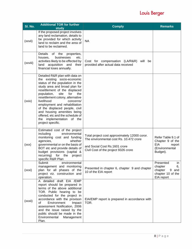
8 | P a g e
Sl. No. Additional TOR for further
study Comply Remarks
(xxvii)
If the proposed project involves any land reclamation, details to be provided for which activity land to reclaim and the area of land to be reclaimed.
NA
(xxviii)
Details of the properties, houses, businesses etc. activities likely to be effected by land acquisition and their financial loses annually.
Cost for compensation (LA/R&R) will be provided after actual data received
(xxix)
Detailed R&R plan with data on the existing socio-economic status of the population in the study area and broad plan for resettlement of the displaced population, site for the resettlement colony, alternative livelihood concerns/ employment and rehabilitation of the displaced people, civil and housing amenities being offered, etc and the schedule of the implementation of the project specific.
(xxx)
Estimated cost of the project including environmental monitoring cost and funding agencies, whether governmental or on the basis of BOT etc and provide details of budget provisions (capital & recurring) for the project specific R&R Plan
Total project cost approximately 12000 coror. The environmental cost Rs. 10.472 crore and Social Cost Rs.1601 crore Civil Cost of the project 9326 crore
Refer Table 9.1 of Chapter 9 of the EIA report (Environmental Budget).
(xxxi)
Submit environmental management and monitoring plan for all phases of the project viz. construction and operation.
Presented in chapter 6, chapter 9 and chapter 10 of the EIA report
Presented in chapter 6, chapter 9 and chapter 10 of the EIA report
(xxxii)
A detailed draft EIA /EMP report should be prepared in terms of the above additional TOR. Public hearing to be conducted for the project in accordance with the provison of Environment Impact assessment Notification, 2006 and the issue raised by the public should be made in the Environmental Management Plan.
EIA/EMP report is prepared in accordance with TOR.

9 | P a g e
Sl. No. Additional TOR for further
study Comply Remarks

ToR_MMRDA_Navghar_Chirner Page 10f7
•F.No.10-25/2014-IA.III
Government of IndiaMinistry of Environment, Forests & Climate Change
(IA.IIISection)Indira Paryavaran Bhawan,
J or Bagh Road,New Delhi - 110 003.
Dated: 12thJanuary, 2015
ToThe Chief Engineer - Engineering Division,Mj s Mumbai Metropolitan Regional Devl. Authority (MMRDA),Plot NO. C-14 and 15, E Block, Bandra - Kurla Complex,Bandra (E), Mumbai - 400051
Subject: Development of Multimodal Corridor from Navghar to Chirner(Near JNPT) in the State of Maharashtra by MIs MumbaiMetropolitan Regional Development Authority - ToR reg.
Sir,
This has reference to your letter No. Nil dated 17.09.2014 forwardingalong with application seeking for Terms of Reference for the aforesaid project.
2. The proposal was considered by the EAC in its 141st meeting held on26th- 2SthNovember, 2014 and the proponent has informed that:
1. The project involves development of Multimodal Corridor fromNavghar to Chirner (Near JNPT) in the State of Maharashtra.
11. Multi Modal Corridor (Navghar to Chirner) is a single corridor inwhich multiple modes, such as buses, BRT, metro rail and cars,along with utilities such as water, sewage and gas lines arepresent in the same Right of Way.
111. The total length of the multi model corridor project IS
approximately SOKm.IV. Proposed Multi Model Corridor start from Navghar (Near
Juchandra, NH-S) and end at Chirner (near JNPT). The projectroad falls in the Tehsils of Vasai, Bhiwandi, Kalyan, Ambernath,Panvel, Uran in the Districts Thane and Raigad in Maharashtra.
v. Land use pattern within 10 km on either side of Multi ModelCorridor project area is agriculture, forest, sanctuaries, mangrove,commercial, residencies, urban & villages.
VI. It is a green field project and the proposed right of way (RoW)iskept as 99 m to accommodate access controlled highway lanes,service lanes, parking lane, pedestrian foot path and a metrofacility at the Centre (30 m).
Vll. Approximately 725 hectares of land is proposed to be acquired inwhich mostly is agriculture, forest, mangrove and mud areas.
Vlll. There is one National Park (Sanjay Gandhi national Park) and twoSanctuaries (Karnala Bird Sanctuary and Tungreshwar WildlifeSanctuary) are located within the 10 km radius of the project.

•ix. Project (Multi Model Corridor) traverse through the Sanjay Gandhi
National Park and will divert 14.4 ha of National Park land.Proposed Multi Model Corridor is located 153 m away from theboundary of Tungareshwar Wildlife Sanctuary and 5816 m awayfrom the boundary of Karnala Bird Sanctuary.
x. Matheran Ecological Sensitive Zone is located within 10 kmradius of the project and its boundary is 105m away from theproposed alignment of the project.
Xl. The project does traverse through forest land and mangroves atfew locations.
xu. Project corridor crosses over five rivers namely Kamvadi river,Ulhas river, Kasadi river, Gudha river and Dhartar river.
Xlll. Project corridor also passes through the costal/low lying areas.xiv. 26 bridges, 04 ROB's, 10 Interchanges, 4 Flyovers, 34 Vehicular
Underpasses, 21 Pedestrian underpasses, 19.1 km elevated areproposed.
xv. Service Road has been provided.XVI. Approximately 3200 families are going to be affected because of
land acquisition & resettlement.XVll. Plantation will be done on the available spare RoW.
XVlll. CRZ study, Wildlife Clearance proposal and environmentalmonitoring are under process.
XlX. The approximate budget for environmental management worksworked out to Rs. 15 Crores. Land Acquisition includingacquisition of structures and R & R Costs for resettlement andcompensation is estimated as Rs. 1601 Crores. The estimated civilcost of the project is approximately Rs. 9326 Crores.
xx. There are no court cases/violation pendingwith the projectproponent.
3. The Expert Appraisal Committee (EAC)has considered the proposal inits 141st meeting held on 26th - 28th November, 2014 and recommended for theTOR with the following specific TOR with general conditions for preparation ofthe Environment Impact Assessment (EIA) Report and EnvironmentManagement Plan (EMP) in respect of the Development of MultimodalCorridor from Navghar to Chirner (Near JNPT) in the State of Maharashtraby M/s Mumbai Metropolitan Regional Development Authority:
(i) Justification for selecting the alignment along with the variousalternatives considered, procedures and criteria adopted forselection of the final alternative with reasons.
(ii) Submit detailed alignment plan, with details such as nature ofterrain (plain, rolling, hilly), land use pattern, habitation, croppingpattern, forest area, environmentally sensitive places, mangroves,notified industrial areas, sand dunes, sea, river, lake, details ofvillages, teshils, districts and states, latitude and longitude forimportant locations falling on the alignment by employing remotesensing techniques followed by ground truthing and also throughsecondarydaQ:::S.
ToR_MMRDA_Navghar_Chirner Page 2 of7

ToR_MMRDA_Navghar _Chimer Page 3 of 7
•(iii) The proposal indicates the acquisrtion of 14.4 ha forest land in
Sanjay Gandhi National Park. Necessary permission from NBWLand stage -I forestry clearance shall be obtained. The grant of ToRshall not be cited as a reason for grant of approvals for diversion ofSanctuary land/Forest land for the project.
(iv) The project involves removal of mangroves, necessary permissionfrom High Court of Bombay shall be obtained as applicable.
(v) Any litigation(s) pending against the proposed project and/ or anydirections or orders passed by any court of law/any statu toryauthority against the project is to be detailed out.
(vi) Submit Land use map of the study area to a scale of 1: 25,000based on recent satellite imagery delineating the crop lands (bothsingle and double crop), agricultural plantations, fallow lands,waste lands, water bodies, built-up areas, forest area and othersurface features such as railway tracks, ports, airports, roads, andmajor industries etc. and submit a detailed ground surveyed mapon 1:2000 scale showing the existing features falling within theright of way namely trees, structures including archaeological &religious, monuments etc. if any.
(vii) Study regarding the Animal bypasses / underpasses etc. acrossthe Sanctuary and habitation areas shall be carried out.
(viii) The information should be provided about the number of trees tobe cut, their species and whether it also involved any protected orendangered species. Necessary green belt shall be provided onboth side of the highway with proper central verge and costprovision should be made for regular maintenance.
(ix) If the proposed route is passing through a city or town, withhouses and human habitation on the either side of the road, thenecessity for provision of bypasses/ diversions/under passes shallbe examined and submitted. The proposal should also indicate thelocation of wayside amenities, which should include petrolstation/ service centre, rest areas including public conveyance, etc.
(x) Submit details about measures taken for the pedestrian safety andconstruction of underpasses and foot-over bridges along withflyovers and interchanges.
(xi) Examine and submit the details of use of fly ash in the roadconstruction, if the project road is located within the 100 km fromthe Thermal Power Plant.
(xii) Examine and submit the details of sand quarry, borrow area andrehabilitation.
(xiii) The air quality monitoring should be carried out in accordancewith the new notification issued on 16th November, 2009.
•(xiv) Identify project activities during construction and operation
phases, which will affect the noise levels and the potential forincreased noise resulting from this project. Discuss the effect ofnoise levels on near by habitation during the construction andoperational phases of the proposed highway. Identify noisereduction measures and traffic management strategies to bedeployed for reducing the negative impact if any. Prediction ofnoise levels should be done by using mathematical modelling atdifferent representative locations.
(xv) Examine the impact during construction activities due togeneration of fugitive dust from crusher units, air emissions fromhot mix plants and vehicles used for transportation of materialsand prediction of impact on ambient air quality using appropriatemathematical model, description of model, input requirement andreference of derivation, distribution of major pollutants andpresentation in tabular form for easy interpretation shall becarried out.
(xvi) Also examine and submit the details about the protection toexisting habitations from dust, noise, odour etc. duringconstruction stage.
(xvii) If the proposed route involves cutting of earth, the details of areato be cut, depth of cut, locations, soil type, volume and quantity ofearth and other materials to be removed with location of disposal/dump site along with necessary permission.
(xviii) If the proposed route is passing through low lying areas, details offill materials and initial and final levels after filling above MSL,should be examined and submit.
(xix) Examine and submit the water bodies including the seasonal oneswithin the corridor of impacts along with their status, volumetriccapacity, quality likely impacts on them due to the project.
(xx) Examine and submit details of water quantity required and sourceof water including water requirement during the constructionstage with supporting data and also classification of ground waterbased on the CGWA classification.
(xxi) Examine and submit the details of measures taken duringconstructions of bridges across river / canal/ major or minor drainskeeping in view the flooding of the rivers and the life span of theexisting bridges. Provision of speed breakers, safety signals,service lanes and foot paths should be examined at appropriatelocations through out the proposed road to avoid the accidents.
(xxii) If there will be any change in the drainage pattern after theproposed activity, details of changes shall be examined and
submitted. d2.-.ToR_MMRDA_Navghar_Chirner Page 4 of 7
ToR_MMRDA_Navghar_Chirner Page 5 of 7
•(xxiii)If there is a possibility that the construction/widening of road will
cause impact such as destruction of forest, poaching, reductionsin wetland areas, if so, examine the impact and submit details.
(xxiv)Submit the details of road safety, signage, service roads, vehicularunder passes, accident prone zone and the mitigation measures.
(xxv) IRe guidelines shall be followed for widening & upgradation ofroad.
(xxvi)Submit the details of social impact assessment due to theproposed construction of road.
(xxvii)If the proposed project involves any land reclamation, details to beprovided for which activity land to reclaim and the area of land tobe reclaimed.
(xxviii) Submit the details of the properties, houses, businesses etc.activities likely to be effected by land acquisition and theirfinancial loses annually.
(xxix)Detailed R&Rplan with data on the existing socio-economic statusof the population in the study area and broad plan forresettlement of the displaced population, site for the resettlementcolony, alternative livelihood concerns/employment andrehabilitation of the displaced people, civil and housing amenitiesbeing offered, etc and the schedule of the implementation of theproject specific
(xxx) Estimated cost of the project including environmental monitoringcost and funding agencies, whether governmental or on the basisof BOT etc and provide details of budget provisions (capital &recurring) for the project specific R&RPlan.
(xxxi)Environmental management and monitoring plan for all phases ofthe project viz. construction and operation be submitted.
(xxxii)A detailed draft EIA/EMP report should be prepared in terms ofthe above additional TOR. Public Hearing to be conducted for theproject in accordance with the provisions of Environment ImpactAssessment Notification, 2006 and the issues raised by the publicshould be addressed in the Environmental Management Plan.
General Guidelines
(i) The EIA document shall be printed on both sides, as for aspossible.
(ii) All documents should be properly indexed, page numbered.
(iii) Period/date of data collection should be clearly indicated.
(iv) Authenticated EnglishRegional languages.c.
translation of all material provided In
•(v) The letter/application for EC should quote the MoEF&CC File No.
and also attach a copy of the letter prescribing the TOR.
(vi) The copy of the letter received from the Ministry on the TORprescribed for the project should be attached as an annexure tothe final ErA-EMP Report.
(vii) The final ErA-EMP report submitted to the Ministry mustincorporate the issues in TOR and that raised in Public Hearing.The index of the final ErA-EMP report, must indicate the specificchapter and page no. of the ErA-EMP Report where the specificTOR prescribed by Ministry and the issue raised in the P.H. havebeen incorporated. Questionnaire related to the project (posted onMoEF&CC website) with all sections duly filled in shall also besubmitted at the time of applying for EC.
(viii) Grant of TOR does not mean grant of EC.
(ix) Grant of TOR/EC to the present project does not mean grant ofapprovals in other regulations such as the Forest (Conservation)Act 1980 or the Wildlife (Protection) Act, 1972.
(x) Grant of EC is also subject to Circulars issued under the EIANotification 2006, which are available on the MoEF&CC website:www.envfor.nic.in.
(xi) The status of accreditation of the EIA consultant with NABET/ QClshall be specifically mentioned. The consultant shall certify thathis accreditation is for the sector for which this EIAis prepared.
(xii) On the front page of ErA/EMP reports, the name of theconsultant/ consultancy firm along with their complete detailsincluding their accreditation, if any shall be indicated. Theconsultant while submitting the ErA/EMP report shall give anundertaking to the effect that the prescribed TORs (TORproposedby the project proponent and additional TOR given by the MoEF)have been complied with and the data submitted is factuallycorrect (Refer MoEF office memorandum dated 4th August, 2009).
(xiii) While submitting the ErA/EMP reports, the name of the expertsassociated with/involved in the preparation of these reports andthe laboratories through which the samples have been gotanalysed should be stated in the report. It shall clearly beindicated whether these laboratories are approved under theEnvironment (Protection) Act, 1986 and the rules made thereunder (Please refer MoEF office memorandum dated 4th August,2009). The project leader of the EIA study shall also be mentioned.
(xiv) All the TOR points as presented before the Expert AppraisalCommittee (EAC)shall be covered.
4. A detailed draft ErA/EMP report should be prepared in terms of theabove additional ToRs and should be submitted to the State Pollution Control
ToR_MMRDA_Navghar_Chirner ~. Page 6 of 7

•Board for conduct of Public Hearing. Public Hearing to be conducted for theproject in accordance with the provisions of Environmental Impact AssessmentNotification, 2006 and the issues raised by the public should be addressed inthe Environmental Management Plan. The Public Hearing should be conductedbased on the ToR letter issued by the Ministry and not on the basis of Minutesof the Meeting available on the web-site.
5. You are required to submit the detailed final EIA/EMP prepared as perToRs including issues raised during Public Hearing to the Ministry forconsidering the proposal for environmental clearance within 3 years as per theMoEF&CCO.M. No.J-11013/41/2006-IA-II(I) (P)dated 08.10.2014.
6. The consultants involved in the preparation of EIA/EMP report afteraccreditation with Quality Council of India/National Accreditation Board ofEducation and Training (QCI/NABET) would need to include a certificate inthis regard in the EIA/EMP reports prepared by them and data provided byother Organization(s)/Laboratories including their status of approvals etc. videnotification of the MoEF dated 19.07.2013.
7. The prescribed ToRs would be valid for a period of three years forsubmission of the EIA/EMP Reports.
(Dr.Ma~~~Director
Copy to:
The Member Secretary, Maharashtra Pollution Control Board, KalpataruPoints, 3rd & 4th floor, Opp. Cine Planet, Sion Circle, Sion (E), Mumbai - 400022, Maharashtra
ToR_MMRDA_Navghar_Chirner Page 7 of 7

•