Environmental Criteria Manual Section 1.4 - Erosion and ...
19
RULE NO .: R161-16.19 POSTING DATE: October 5, 2016 NOTICE OF PROPOSED RULE The Director of Watershed Protection Department proposes to adopt the following rule after November 6, 2016. Comments on the proposed rule are requested from the public. Comments should be submitted to Dana McGehee, 505 Barton Springs Road, Suite 1200, Austin Texas, 78704, 974-2634, or via email at [email protected]. To be considered, comments must be submitted before November 6, 2016, the 32nd day after the date this notice is posted. A summary of the written comments received wi ll be included in the notice of rule adoption that must be posted for the rule to become effective. An affordability impact statement regarding the proposed rule has been obtained and is available for inspection or copying at the address noted in the preceding paragraph. EFFECTIVE DATE OF PROPOSED RULE A rule proposed in this notice may not become effective before the effective date established by a separate notice of rule adoption. A notice of rule adoption may not be posted before November 6, 2016 (the 32nd day after the date of this notice) or not after January 3, 2017 (the 90th day after the date of this notice). If a proposed rule is not adopted on or before January 3, 2017 it is automatically withdrawn and cannot be adopted without first posting a new notice of a proposed rule. TEXT OF PROPOSED RULE A copy of the complete text of the proposed rule is available for public inspection and copying at the following locations. Copies may be purchased at the locations at a cost of ten cents per page: Watershed Protection Department, located at 505 Barton Springs Road, Suite 1200, Austin, TX, 78704; and Office of the City Clerk, City Hall, located at 301 West 2nd Street, Austin, Texas. Rl61 -16.19 Posting Notice
Transcript of Environmental Criteria Manual Section 1.4 - Erosion and ...

RULE NO.: R161-16.19
POSTING DATE: October 5, 2016
NOTICE OF PROPOSED RULE
The Director of Watershed Protection Department proposes to adopt the following rule after November 6, 2016.
Comments on the proposed rule are requested from the public. Comments should be submitted to Dana McGehee, 505 Barton Springs Road, Suite 1200, Austin Texas, 78704, 974-2634, or via email at [email protected]. To be considered, comments must be submitted before November 6, 2016, the 32nd day after the date this notice is posted. A summary of the written comments received will be included in the notice of rule adoption that must be posted for the rule to become effective.
An affordability impact statement regarding the proposed rule has been obtained and is available for inspection or copying at the address noted in the preceding paragraph.
EFFECTIVE DATE OF PROPOSED RULE
A rule proposed in this notice may not become effective before the effective date established by a separate notice of rule adoption. A notice of rule adoption may not be posted before November 6, 2016 (the 32nd day after the date of this notice) or not after January 3, 2017 (the 90th day after the date of this notice).
If a proposed rule is not adopted on or before January 3, 2017 it is automatically withdrawn and cannot be adopted without first posting a new notice of a proposed rule.
TEXT OF PROPOSED RULE
A copy of the complete text of the proposed rule is available for public inspection and copying at the following locations. Copies may be purchased at the locations at a cost of ten cents per page:
Watershed Protection Department, located at 505 Barton Springs Road, Suite 1200, Austin, TX, 78704; and
Office of the City Clerk, City Hall, located at 301 West 2nd Street, Austin, Texas.
Rl61 -16.19 Posting Notice

BRIEF EXPLANATION OF PROPOSED RULE
Rl61-16.19: Additions and revisions to the Environmental Criteria Manual Section 1.4, Erosion and Sediment Control, Environmental Criteria Manual Section 1.6, Design Guidelines for Water Quality Control, and Environmental Criteria Manual Appendix S-1, Cost Estimates For Erosion/Sedimentation Control Fiscal Surety, as follows:
Environmental Criteria Manual Section 1.4 - Erosion and Sedimentation Control
• 1.4.4 - Plan Development and Implementation o Remove reference to Appendix P-7. This Appendix no longer exists.
Environmental Criteria Manual Section 1.6 - Design Guidelines for Water Quality Controls
• 1.6.2.B - Water Quality Volume Diversion Structures o Update stacked detention language to clarify when a splitter box is
required and inline pond requirements.
• 1.6.2.C - Basin Liners o Added criteria regarding handling of liner penetrations regarding
submerged inlets and stonn sewers.
• 1.6.3.C - Major Maintenance Requirements o Added language regarding watertight requirements for retaining walls, and
mortared or grouted rock walls.
• 1.6.7.4 - Infiltration Rate Evaluation o Added note setting maximum infiltration rate (0.20 in/hr) for retention
irrigation SCMs.
• 1.6.7.A.2 - Minimum Design Criteria for Retention Basin o Added reference to DCM 1.2.4.E
• 1.6.7.A.4 - Minimum Design Criteria for the Irrigation System o Added maximum infiltration rate (0.20 in/hr) modifications for retention
irrigation SCMs.
Environmental Criteria Manual Appendix S-1 - Cost Estimates for Erosion/Sedimentation Control Fiscal Surety
• Removed curb inlet protection cost estimate.
Rl61-16.19 Posting Notice

AUTHORITY FOR ADOPTION OF PROPOSED RULE
The authority and procedure for the adoption of a rule to assist in the implementation, administration, or enforcement of a provision of the City Code is established in Chapter 1-2 of the City Code. The authority to regulate water quality is established in Chapter 25-8 of the City Code.
Rl 61-16.19 Posting Notice
CERTIFICATION BY CITY ATTORNEY
By signing this Notice of Proposed Rule (R 161-16.19), the City Attorney certifies the City Attorney has reviewed the rule and finds that adoption of the rule is a valid exercise of the Director's administrative authority.
REVIEW AND APPROVED
ntalion, P.E. , Director atershed Protection Department
Anne Morgan City Attorney
Date: ___ \_(.)-+-/~--+\ _,_\ _~---
This Notice of Proposed Rule was posted on a central bulletin board at City Hall by the City Clerk. Date and time stamp is on the front of the notice.
R161 -16.19 Posting Notice
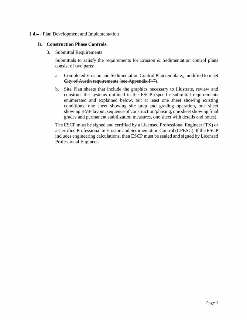
1.4.4 - Plan Development and Implementation
B. Construction Phase Controls. 3. Submittal Requirements
Submittals to satisfy the requirements for Erosion & Sedimentation control plans consist of two parts:
a. Completed Erosion and Sedimentation Control Plan template,. modified to meet City of Austin requirements (see Appendix P-7).
b. Site Plan sheets that include the graphics necessary to illustrate, review and construct the systems outlined in the ESCP (specific submittal requirements enumerated and explained below, but at least one sheet showing existing conditions, one sheet showing site prep and grading operation, one sheet showing BMP layout, sequence of construction/phasing, one sheet showing final grades and permanent stabilization measures, one sheet with details and notes).
The ESCP must be signed and certified by a Licensed Professional Engineer (TX) or a Certified Professional in Erosion and Sedimentation Control (CPESC). If the ESCP includes engineering calculations, then ESCP must be sealed and signed by Licensed Professional Engineer.
Page 1

1.6.2 - General Design Guidelines
B. Water Quality Volume Diversion Structures. 1. Off-line SCMs may be are required to have a diversion structure or splitter box which
will capture the water quality volume. A typical approach for achieving capture of the water quality volume is to construct a diversion weir in the stormwater channel. For SCMs that require a diversion structure the following minimum design standards must be provided: a) The height of the diversion weir must be equal to or greater than the surface
elevation of the water quality volume in the SCM. b) The diversion structure must be capable of passing the peak flow rate of the
twenty-five (25) year storm into the stormwater control measure. c) The maximum velocity entering the water quality basin shall not exceed two (2)
feet per second. d) When runoff in excess of the water quality volume enters the stormwater channel
it will spill over the diversion weir. The diversion weir must be designed to pass the peak flow rate of the one hundred (100) year design storm past the SCM with a head over the diversion weir of no more than one foot.
e) The water quality pond design shall allow enough freeboard to pass the design flow rate for the 100 year storm over the splitter/diversion structure without overtopping of any side walls of the pond, plus an additional 5% of the total fill height or three inches, whichever is greater, to allow for construction irregularities and long term soil settling.
f) As an alternative the design engineer can size the diversion structure for the flowrate of the twenty-five (25) year inflow hydrograph that will fill the pond; a hydraulic and hydrologic analysis must be provided that conforms with accepted procedures, as defined in the Drainage Criteria Manual.
Figures 1-48 through 1-50 in Appendix V of this manual presents examples of these structures.
2. SCMs that propose to stack the detention volume above the water quality volume must comply with the following criteria: SCMs that may be are allowed to stack the required detention volume or allow all storm events to flow through the SCM above the water quality volume are as follows:
• Partial sedimentation with sand filtration or biofiltration controls
• Full sedimentation with sand filtration or biofiltration controls
• Retention Irrigation controls that are not subject to compliance with the SOS ordinance.
• Rainwater Harvesting controls
Page 2

• Rain Gardens
• Porous Pavement
The following minimum design criteria must be provided: In-line SCMs that propose to stack the required detention volume or allow all storm events to flow through the SCM above the water quality volume must comply with the following criteria: a) The velocity of the flows entering the SCM for the developed 100 year peak
flow must not exceed two feet per second. b) Velocity breaks and energy dissipation should be incorporated into the design to
reduce erosive impacts on the SCM and to protect the medium (sand or biofiltration) from washing out or eroding.
c) Detention pond and SCM wall elevations must meet the minimum freeboard requirements provided in the Drainage Criteria Manual.
C. Basin Liners. All wet ponds require an impermeable liner. Impermeable liners are also
required for water quality basins located over the Edwards Aquifer Recharge Zone and in areas where there is surface runoff to groundwater conductivity. Impermeable liners may be clay, concrete, geosynthetic clay liner (GCL), geomembrane, or other approved liner, depending on the application. The analysis and design should entail a comprehensive review of the site specific conditions to determine the most appropriate type of liner for the site, and should include a stability assessment of the pond side slope. The guidelines below must be used for the design of liners for wet ponds, sedimentation basins, filtration basins, and retention ponds as applicable. The criteria in item 1 is applicable to any size basin or pond, while the criteria in item 2 may be applied to sedimentation basins, filtration basins and retention ponds that are less than 1,000 square feet in area. When required for sedimentation/filtration basins, the liner must underlie both the sedimentation basin and filtration basin and any gabion wall areas. 1. Wet Ponds, Sedimentation Basins, Filtration Basins, and Retention PondsThe
following criteria applies to all SCMs where a basin liner is required. There are a number of important engineering design and construction considerations for wet pond liners and other basin liners. A geotechnical engineer must be involved in all aspects of the liner design. All liner studies, plans, details, specifications and other related documents must be sealed by a geotechnical engineer. Careful attention must be paid to each of the following areas:
a.• Liner subgrade - A stable subgrade is very important in the construction of the pond or basin. Careful evaluation must be conducted to ensure the liner will be placed on a suitable base. If any voids are encountered, proper geotechnical analysis must be performed to ensure that the integrity of the liner can be maintained. Proof rolling must be conducted as necessary to determine the suitability of the subgrade, and any suspect areas must be reworked and recompacted, or the weak soils removed and replaced with suitable fill material. The subgrade for geomembrane or GCL must be smooth and contain no particles greater than 0.375 inch diameter.
Page 3

b.• Liner characteristics - At least three types of liners can be considered, including a clay liner of appropriate thickness and permeability, a geomembrane liner, and GCL. Alternative liner designs may also be considered.
(1).o If geomembrane is used, it must have a minimum thickness of thirty (30) mils and be ultraviolet resistant. Use of a geomembrane also requires that a suitable geotextile fabric be placed on the top and bottom of the membrane for puncture protection if any particles greater than 0.375 inch are present in the cover soil or subgrade surface, respectively. The geotextile material must have a minimum unit weight of 8 oz./sq. yd., a minimum puncture strength of 125 lbs., a minimum Mullen Burst Strength of 400 psi, and a minimum tensile strength of 200 lbs. The designer must demonstrate the liner's impermeability, and the method of liner protection to be used during maintenance and sediment removal operations. Equivalent methods for protection of the geomembrane liner will be considered by the Watershed Protection Department on a case by case basis. Equivalency will be judged on the basis of ability to protect the geomembrane from puncture, tearing and abrasion. Individuals installing geomembrane liners must be trained and/or certified by the liner manufacturer. Standard Details 661-4 and 661-5 illustrate acceptable geomembrane liner end details for use on concrete walls, stacked stone walls, and earthen embankments.
(2).o If a clay liner is used, it must be designed for the site-specific conditions by a geotechnical engineer, and must have a minimum thickness of twelve (12) inches or greater. Coefficient of permeability must be 1x10⁻⁷ cm/sec or less. Other parameters must be as follows: plasticity index of not less than 15; liquid limit of not less than 30; and at least 30% clay particles passing the No. 200 sieve, with a maximum particle size of 1 inch. Soil must be processed to reduce clod size as much as possible prior to compaction and compaction of the lifts must be done using footed rollers. Clay compaction must be no less than 95% of Standard Proctor Density at or above optimum moisture content or 90% of Modified Proctor Density at a moisture content between 1% dry and 3% wet of optimum. Soil sampling and testing must be conducted on the borrow source and installed liner samples as applicable. Liner material verification sampling and testing should occur at frequencies which must be in accordance with the QA/QC plan. In-situ materials may be used if it can be demonstrated that all required liner parameters will be met. If the clay liner is to be overlain by a drainage layer, a suitable geotextile fabric must be placed on the surface of the liner prior to placement of the drainage layer to prevent plugging of the drain by the clay liner. Standard Detail 661-5 illustrates this placement.
(3).o Geomembrane or GCL liner placement over excavated rock requires installation of protective material to prevent damage to the liner. Examples of protective material include spray-on fiberglass, additional clay liner material, or placement of a geosynthetic fabric.
Page 4
(4).o An alternative liner design may be approved by the Director of the Watershed Protection Department if it can be demonstrated by the responsible party that the liner is at least equivalent to or exceeds the above requirements.
c.• Handling of liner penetrations - Liner penetrations are one of the areas of the pond or basin that are most susceptible to leakage. It is critical that the design and construction of these areas pay special attention to liner continuity around these interface points. Detailed analysis must be performed related to the handling of all areas of liner penetrations such as pipe inlet and outlet structures, headwalls, and areas where concrete access ramps, maintenance and pump pads interface with the liner. Penetrations for wet ponds should be placed to minimize the hydraulic head over the penetration. Consideration must be given to the need for special applications such as anti-seep collars, gaskets, clay or bentonite plugs, special backfill and compaction, and other measures to prevent leakage around all these areas. Intake pipes should be doubled-walled or lined below the elevation of the water quality volume or permanent pool elevation.
(1). Submerged Inlets and Storm Sewers – Due to excessive leakage issues submerged inlets and storm sewers to SCMs are to be avoided whenever possible. In situations where site conditions require a submerged inlet or storm sewer then the portion of the inlet pipe that is placed below the water quality elevation must be designed to store water, not simply convey it. In these situations the pond liner must extend and surround the portion of the inlet pipe or storm sewer that is designed to be under water and all structural elements & piping below the water quality elevation shall be watertight. Acceptable watertight piping includes gasketed RCP, PVC, and wastewater grade HDPE. Leak testing of the system will be performed to verify that the system is watertight and able to perform as designed.
d.• Protecting the liner from erosion - The integrity of the liner, particularly a clay liner, can be severely compromised by any erosion that may occur at the surface of the liner. The design must provide appropriate mechanisms to prevent erosion of the liner at all areas, including the inlet structure and the separation berm between the forebay and main pool of wet ponds. Additionally, the liner must be continuous under wet pond separation berms to minimize the potential for leakage at the equalization/interbasin pipe.
e.• Protecting the liner against damage and loss of moisture - It is imperative that the clay liner be kept moist during construction and prior to the time the basin is filled. Otherwise, cracks can develop in the clay, particularly during the hotter months of the year, thereby rendering it susceptible to leakage. For wet ponds, provisions must be included in the construction documents that require the contractor to protect the liner against loss of moisture until the basin is completely filled. For all ponds, damage to unprotected clay, GCL, or geomembrane liners can also occur due to passage of equipment during construction or during future sediment removal and maintenance operations. To minimize the possibility of damage and drying, all
Page 5
liner designs should include a protective soil layer over the liner with a minimum thickness of 12 inches for clay liners, and 24 inches for GCL and geomembrane (the 24-inch thickness can be reduced for liners which are never to undergo traffic by heavy equipment or are otherwise protected from heavy equipment). The protective cover layer includes 6-inches of topsoil per Section 1.4.7.B.
f.• Liner Plans and Specifications - The engineer must prepare the necessary plans and specifications to provide the contractor clear direction for the construction of the liner and all related components. Construction details must be included for all liner cross-sections, penetrations, and any other areas requiring special attention and/or guidance to ensure proper construction. A scale drawing of the area to be lined, including a grid established across the base and side slopes of the pond or basin with target elevations shown, must also be prepared by the engineer. This grid will provide a basis for verification of liner thickness during construction and will be used for the purpose of recording elevation data prior to placement of the initial lift and following placement of the final lift. All required testing, standards, procedures, and material properties must be spelled out in detail in the documents. Parties who are responsible for any surveying, sampling, testing and other verification requirements must be identified in the documents.
g.• Groundwater Control - Liners constructed below groundwater will require dewatering as necessary to allow construction of the liner. To prevent damage to the liner due to uplift pressures after termination of dewatering or during future maintenance, the liner must include placement of sufficient soil ballast or additional thickness of clay liner to resist any uplift pressures. Alternative designs to relieve liner uplift pressure (French drain, etc.) will be considered and must be approved by the Watershed Protection Department.
h.• Construction Quality Assurance/Quality Control Plan - A construction Quality Assurance/Quality Control (QA/QC) Plan must be prepared by the engineer for the purpose of providing a basis for all construction/installation and testing of the liner system during the liner construction process. The QA/QC plan must be approved by the City prior to liner construction.
(1).o For clay liners, the QA/QC plan must include, but not be limited to, the following items: recordkeeping documents, including daily construction reports, inspection and test data sheets, non-conformance and corrective measure reports, design and specification changes, and all other documentation accumulated by inspection personnel during construction; pre-construction soil sampling, testing and documentation protocol, including the type of information to be documented for each sample, and the test procedures to be used; protocol during construction, including the monitoring of the subgrade, as well as material placement (including items such as density testing and moisture content, lift thickness and bonding, processing of soil and reduction of clods, footed compaction equipment, and number of passes of compaction equipment), sampling and testing procedures, frequencies and other requirements. Also, the handling of any liner perforations as a result of various types of testing must be
Page 6

addressed along with guidance on how to address any deficiencies that may be discovered, including corrective measures to be taken.
(2).o For geomembrane and GCL liners, the QA/QC plan must include, but not be limited to, the following items: geomembrane/GCL manufacturing and delivery data requirements, including raw materials properties, roll and production quality assurance and control data requirements, along with transportation, handling and storage requirements, and conformance testing; installer qualifications requirements; installation requirements, including surface preparation, system anchorage, geomembrane/GCL placement (including, but not limited to panel identification, placement and installation schedule), seaming information (including, as applicable to geomembrane or GCL, seam layout, preparation, equipment, weather conditions, trial welds, general procedures, non-destructive testing and destructive testing), identification of defects and repair procedures, and geomembrane/GCL acceptance procedures.
i. Soils and Liner Evaluation Report (SLER), Geosynthetic Clay Liner Evaluation Report (GCLER), or Geomembrane Liner Evaluation Report (GLER) - All liner construction and QA/QC activities must be under the supervision of an independent licensed engineer with experience in geotechnical engineering. The engineer or designated representative must be on site during all significant liner construction activities, including but not limited to:
1. At the beginning of liner construction to inspect subgrade acceptability; 2. During the processing of clay liner material for placement to ensure
adequate moisture conditioning and particle size reduction; 3. During placement of clay liner lifts to ensure 6 inch maximum lift depth is
not exceeded and compaction is sufficient; 4. During all geomembrane installation; 5. During clay and geomembrane liner testing; 6. Prior to placement of successive clay lifts to verify acceptability of prior lift
surface; 7. During construction of penetrations and any other construction that will
affect the integrity of the liner (access ramps, pump pads, etc.). 8. During placement of protective soil layer.
• Following completion of the liner construction, SLER, GCLER, or GLER (as applicable for the type of liner installed) must be prepared under the direction of and sealed by the engineer and submitted to the City. The report is intended to provide documentation of all installation methods and testing procedures conducted during the installation of the liner and to provide evidence that the liner was constructed in accordance with the construction plans, technical specifications and QA/QC plan.
Page 7
j.• Water Level Monitoring for liner integrity verification in wet ponds - After the filling and installation of aquatic vegetation in a wet pond, the water level of the permanent pool shall be measured monitored for a minimum of eight weeks. The engineer shall specify the method and frequency of monitoring, and the responsible party for conducting water level monitoring. The engineer shall perform a water balance, as specified in 1.6.6.C. 5, to determine that the water loss does not exceed anticipated losses from calculated liner leakage, evaporation, plant transpiration and discharge. All monitoring data and calculations must be documented and submitted to the City of Austin for review.
2. Sedimentation Basins, Filtration Basins and Retention Ponds less than 1,000 square feet in area. Concrete liners may be used for sedimentation basins, filtration basins and retention ponds less than one thousand (1,000) square feet in area. Concrete must be five (5) inch thick Class A or better as defined in the City of Austin Standard Specifications and must be reinforced by steel wire mesh. The steel wire mesh must be six (6) gauge wire or larger and six (6) inch by six (6) inch mesh or smaller. An Ordinary Surface Finish (as specified in Standard Specification Item 410.25) is required. When the underlying soil is clay or has an unconfined compressive strength of one-quarter (0.25) ton per square foot or less, the concrete must have a minimum six (6) inch compacted aggregate base consisting of coarse sand and river stone, crushed stone or equivalent with diameter of three-quarters (0.75) to one (1) inch. Where visible, the concrete must be inspected annually and all cracks must be sealed.
Page 8

1.6.3 Maintenance and Construction Requirements
B. Maintenance Requirements—Design and Construction. The design of drainage facilities (including but not limited to headwalls, open channels, storm sewers, area inlets, and detention, retention and stormwater control measures and their appurtenances) shall comply with the requirements of Section 1.2.4.E of the Drainage Criteria Manual. In addition, SCMs shall comply with the following construction requirements:
1. Sediment removed during construction of a detention, retention, or water quality facilities may be disposed of on-site if properly stabilized according to the practices outlined in the erosion and sedimentation control criteria found in Section 1.4.0 of this manual. After the City of Austin has accepted a stormwater facility disposal of sediment must be at an approved landfill.
2. During construction of SCMs, temporary erosion and sedimentation controls shall be maintained.
3. If runoff is to enter the sand filtration chamber of a water quality control facility prior to completion of site construction and revegetation, inspection and maintenance of all temporary erosion/sedimentation controls are required, as described in the Environmental Criteria Manual Section 1.4.4, to prevent heavy sediment loads caused by home construction from clogging the filtration media.
4. In all cases, trees shall be preserved according to the requirements of Section 3 of the Environmental Criteria Manual. The access drive and staging area shall be designed to preserve trees 8" (inches) in diameter and greater to the maximum extent possible. Trees 8" in diameter and larger shall be surveyed and shown for the proposed access easement at the time of construction plan permitting.
5. For filtration systems the design media depth must be verified, accounting for consolidation. If insufficient depth is present, additional media must be added and pre-soaked until the design depth is achieved. Pre-soaking - apply 5-10 gallons of water per square foot of media area within one hour.
6. Retaining Walls – Retaining walls within SCMs require water-tightness. Water-tightness in retaining walls is essential to the function of the structure. Waterstops shall be provided during construction of expansion joints in retaining walls per Standard Specification 414S, Concrete Retaining Walls. 7. Grouted Rock Walls - Grouted rock walls are acceptable only if the design includes an impermeable barrier such as an approved geomembrane liner or reinforced concrete retaining wall. Free standing dry stacked rock walls are not acceptable in any SCM.
Page 9

1.6.7.4 - Infiltration Rate Evaluation
An evaluation of infiltration rate is necessary to determine if infiltration is feasible and to establish design infiltration rates for several of the innovative water quality controls described in Section 1.6.7.
There are three basic steps for evaluating infiltration rate:
1. Desktop study (i.e., soil survey maps or existing geotechnical information). 2. Field sampling (i.e., soil depth verification and textural analysis). 3. In-situ testing (i.e., more rigorous in-situ infiltration or percolation testing).
The design infiltration rate shall be established by applying a minimum factor of safety of 2 to the estimated or measured infiltration rate. A higher factor of safety may be used at the discretion of the design engineer to take into variability associated with assessment methods, soil texture, soil uniformity, influent sediment loads, and compaction during construction.
Table 1.6.7-1 identifies the minimum required steps for establishing the infiltration rate for each applicable water quality control. Although not required, results from in-situ testing may be used to establish infiltration rate for any applicable control.
Table 1.6.7-1. Minimum required steps for establishing infiltration rate.
Desktop Study Field Sampling In-situ Testing
Retention/Irrigation System 2 • •
Vegetative Filter Strip • •
Rainwater Harvesting 1 • • •
Porous Pavement • • •
Rain Garden - Full Infiltration • • •
Rain Garden - Partial Infiltration • •
Note 1: Infiltration evaluation is not required for rainwater harvesting when the system is designed for beneficial reuse (i.e., when capacity for WQV is restored by pumping water to a separate tank).
Note 2: Irrigation area and infiltration field infiltration rates cannot exceed 0.20 inches per hour, see 1.6.7.A.4.b
Page 10

1.6.7.A. - Retention/Irrigation Systems.
2. Minimum Design Criteria for the Retention Basin. Information on water quality volume, diversion structures, and lining requirements can be found in Section 1.6.2 (General Design Guidelines). In addition, applicable requirements of Section 1.6.3 (Maintenance and Construction Requirements) and Drainage Criteria Manual 1.2.4 (Drainage System) must be incorporated in the design. a. Retention Basin Volume. The basin must be of sufficient size to capture and hold the
required capture volume. Retention basins are designed to capture and hold the water quality volume routed to them via diversion structures. All structural elements & piping below the Water Quality elevation shall be watertight. For development in the Barton Springs Zone, refer to Section 1.6.9.3. of this manual for the required capture volume.
b. One-Hundred Year Storm. A bypass capable of conveying the 100-year storm around the basin must be provided.
c. Lining. A liner will be required for a retention basin if the basin is located in the Edwards Aquifer recharge zone in accordance with Section 1. The liner must be designed in accordance with Section 1.6.2.C (Basin Liners). All retention basins are subject to 1.6.3.C.4 (Maintenance and Construction Requirements).
d. Erosion Prevention. The inlets to the retention basin must be designed to prevent erosion of the soil and liner. Rock rip-rap or other erosion prevention systems must be placed at the basin inlet to reduce velocities to less than three feet per second.
e. Access Ramp. A maintenance access ramp, as described in Section 1.6.3, is required for all facilities.
**** 4. Minimum Design Criteria for the Irrigation System or Infiltration Field.
a. Irrigation Timing. (1) The retention basin must be emptied within 72-hours after a rain event ends. (2) Irrigation must be initiated no sooner than 12 hours after the rain event ceases. (3) The irrigation controller must be set to provide alternating, equivalent irrigation
and rest periods until the basin is emptied. (4) The time of irrigation on any area must not exceed the rest time. Continuous
application on any area must not exceed two hours. (5) An adjustable rain sensor must be provided which will normally be set to
temporarily halt irrigation during rainfalls exceeding one half inch. The rain sensor must be able to interrupt irrigation (stop pumps) in the event of subsequent rain events prior to emptying basin. The 12 hour pump delay may initiate after the rain sensor senses the rain event has terminated.
Page 11

(6) Division of the irrigation area into two or more sections such that irrigation occurs alternately in each section is an acceptable way to meet the requirement for a rest period.
b. Irrigation Rate. The infiltration rate at which the soil can accept the irrigated storm water must be derived from the infiltration rate listed in the U.S. Department of Agriculture National Resources Conservation Service (NRCS) Soil Survey for the county, location, and soil type verified to be present at the irrigation site. If a range is given, the lower value of the range is to be used. The design irrigation rate is not to exceed 0.20 inches per hour even if the lower value of the range exceeds that rate. City of Austin field experience has shown that infiltration rates above 0.20 inches per hour do not function as designed and generate significant nuisance ponding and runoff issues. established using the steps outlined in Section 1.6.7.4. Other methods of demonstrating site-specific permeability may be approved by the Director. The application rate may not exceed the infiltration rate on any portion of the irrigation area.
c. Irrigation Area or Infiltration Field. Calculations must be provided which demonstrate that an adequate irrigation area or infiltration field will be provided based on the application rate, soil permeabilityinfiltration rate, water quality volume, and, for irrigation areas, the application rate and actual irrigation time. The irrigation area or infiltration field and system must be included within the water quality easement.
d. Irrigation Area Slope. Irrigation must not occur on land with slopes greater than 10%. e. Piping and Valves.
(1) All irrigation system distribution and lateral piping (i.e. from the pumps to the spray heads) must be Schedule 40 purple PVC. All pipes and electrical bundles passing beneath driveways or paved areas must be sleeved with PVC Class 200 pipe with solvent welded joints. Sleeve diameter must equal twice that of the pipe or electrical bundle. Buried piping must be marked with detectable marking tape labeled "CAUTION: BURIED NON-POTABLE WATER LINE BELOW".
(2) Valves. All valves must be designed specifically for sediment bearing water, and be of appropriate design for the intended purpose. All remote control, gate, and quick coupling valves must be located in ten-inch or larger plastic valve boxes with purple caps. All pipes and valves must be marked to indicate that they contain non-potable water. All piping must be buried to protect it from weather and vandalism. The depth and method of burial must be adequate to protect the pipe from vehicular traffic such as maintenance equipment. Velocities in all pipelines should be sufficient to prevent settling of solids. The irrigation design and layout must be integrated with the tree protection plan and presented as part of the Site Plan or Subdivision Construction Plan.
(3) Systems must include a plug valve to allow flushing at the end of every line.
Page 12

f. Sprinklers. All sprinkler heads must have full or partial circle rotor pop-up heads and must be capable of delivering the required rate of irrigation over the designated area in a uniform manner. Sprinkler heads should have purple caps to indicate non-potable water. Irrigation must not occur beyond the limits of the designated irrigation area and sprinkler heads should be located at least twice the calculated spray radius from any residential lot. Partial circle sprinkler heads must be used as necessary to prevent irrigation beyond the designated limits. Sprinkler heads must be capable of passing solids that may pass through the intake. Sprinkler heads must be flush mounted and encased within a 2 feet × 2 feet concrete housing capable of protecting the head from mowing and service equipment (see Appendix V, Figure 1-59F for an example).
g. Vegetation. The irrigation area must have native vegetation or be restored or re-established with native vegetation, unless approved by the Director. These areas must not receive any fertilizers, pesticides, or herbicides. If landscaped areas are used for irrigation, fertilizers, pesticides, or herbicides must not be applied to those areas and this limitation must be outlined in the Integrated Pest Management (IPM) plan. For publicly maintained systems, fencing or signs must be installed to limit unauthorized use of the irrigation area. If signs are installed, they must include the phrase "Stormwater Irrigation Area - No Trespassing."
h. Soil. The irrigation area must contain a minimum of 12 inches of native or enhanced soil with the appropriate permeability rates. A soils report must be provided and must include at a minimum a soils map verifying soil types in the irrigation area, permeability rates, soil depths, percent of coarse fragments gravel size (2.0 mm diameter) and larger, found on the soil surface and in the subsurface soils, depth of roots, locations of borings or trenches, photographs of exposed soils, location and type of soil enhancement performed, soils testing results, etc. A site visit may be conducted by the city to confirm soil conditions, including when representative trenches have been opened or borings are being conducted. City staff must be given at least 72 hour notice of when borings or trenches are to be backfilled. If soil is enhanced, topsoil or amended topsoil shall meet the requirements of Standard Specification 601S, Salvaging and Placing Topsoil. The condition, type, structure, and quality of the soil shall be conducive to infiltration and to plant growth. If alternative methods of amending soil can be demonstrated to increase the infiltration capacity by at least a factor of three, these methods may be used with approval from the Director of WPD.
i. Geological Features. The irrigation area must not contain any Critical Environmental Feature Buffer Zones.
j. Irrigation Area Buffer. A buffer area of un-irrigated vegetation must be provided downstream of the irrigation area to treat any runoff that may occur from the irrigation area during heavy rainfall or from excessive irrigation. This area must be a minimum of 50 feet in length (in the direction of flow) and be adjacent to all downstream edges of the irrigation area. As an option, a diversion system (e.g. a swale or berm) may be provided to route any runoff to the retention basin. This diversion system must be designed to carry the runoff from the two-year storm.
Page 13

Alternatively, the irrigation area may be located upstream from the development such that any runoff will be routed to the retention pond.
Page 14

APPENDIX S-1 - COST ESTIMATES FOR EROSION/SEDIMENTATION CONTROL FISCAL SURETY (LDC 25-7-65)
Silt Fence .....$3.00 per linear ft.
Rock Berm .....$14.00 per linear ft.
Reinforced Rock Berm .....$16.00 per linear ft.
Triangular Filter Dike .....$3.50 ft.
Mulch Berm .....$4.00 ft.
Mulch Sock (12 inch) .....$4.00 ft.
Mulch Sock (18 inch) .....$6.00 ft.
Hay Bale Dike. .....$3.50 ft.
Stabilized Construction Entrance .....$1000 each
Diversion/Interceptor/Perimeter Dike. .....$3.00 per linear ft.
Interceptor/Perimeter Swale (flat slope) .....$4.00 per linear ft.
Interceptor/Perimeter Swale (rock lined) .....$6.00 per linear ft.
Inlet Protection .....$50 each
Hydromulch seeding < 5,000 sq. yds. (w/topsoil & watering for temporary and permanent revegetation) .....$3.00 per sq yd
Hydromulch seeding > 5,000 sq. yds. (w/topsoil & watering for temporary and permanent revegetation) .....$2.00 per sq yd
Standard 604S Seeding for Erosion Control .....$5.00 per sq yd
Standard 609S Native Grasslands for Erosion Control .....$7.00 per sq yd
Revegetation matting-slopes (wood fiber) .....$1.50 per sq yd
Revegetation matting-channels (synthetic) .....$7.00 per sq yd
Standard 602 S Sodding for Erosion Control .....$5.00 per sq yd
On-site/off-site clean-up and remedy of erosion damage that results from development (only required for sites with LOC greater than 1 acre)
Phase 1: number of acres disturbed within LOC: ____________ × $3000= $____________
Phase 2: number of acres disturbed within LOC: ____________ × $3000= $____________
Phase 3: number of acres disturbed within LOC: ____________ × $3000= $____________
Total fiscal for clean-up = Phase 1+ Phase 2+Phase 3 = $____________
Page 15