entropy
69
Mechanical Engineering National Central University Chapter 6 Entropy
-
Upload
arvidkumar87060 -
Category
Documents
-
view
40 -
download
1
description
thermodynamics
Transcript of entropy

Mechanical Engineering
National Central University
Chapter 6
Entropy

Mechanical Engineering
National Central University
66--22
Ans: No. The represents the net heat transfer during a cycle, which could be positive.
Does a cycle for which violate the Clausiusinequality? Why?
∫ > 0Qδ
∫ Qδ

Mechanical Engineering
National Central University
66--88
Ans: Yes.
Is the value of the integral the same for all reversible processes between states 1 and 2? Why?
∫2
1/TQδ
( )∫ ⎟⎠⎞
⎜⎝⎛=−=∆
2
1revint
12 (*)/ KkJTQSSS δ
that entropy is a property, and like all other properties, it has fixed valued at fixed states.

Mechanical Engineering
National Central University
66--1515
Ans: Never. A reversible adiabatic process is necessarily isentropic
A piston-cylinder device contains nitrogen gas. During a reversible, adiabatic process, the entropy of the nitrogen will (never, sometimes, always) increase.
constants sor 0s 12
===∆ s

Mechanical Engineering
National Central University
66--2121
Ans: Yes. This will happen when the system is losing heat, and the decrease in entropy as a result of thisheat loss is equal to the increase in entropy as a result of irreversibilities.
Is it possible for the entropy change of a closed system to be zero during an irreversible process? Explain.

Mechanical Engineering
National Central University
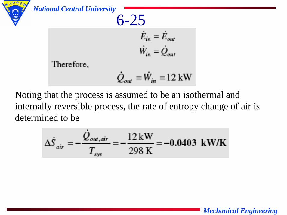
6-25Air is compressed by a 12-kW compressor from P1 to P2.
The air temperature is maintained constant at 250C during this process as a result of heat transfer to the surrounding medium at 100C. Determine the rate of entropy change of the air. State the assumptions made in solving this problem.

Mechanical Engineering
National Central University
6-25Assumptions: 1 This is a steady-flow process since there is no change with time. 2 Kinetic and potential energy changes are negligible. 3 Air is an ideal gas. 4 The process involves no internal irreversibilities such as friction, and thus it is an isothermal, internally reversible process.Properties: Noting that h = h(T) for ideal gases, we have h1 = h2since T1 = T2 = 25°C.Analysis: We take the compressor as the system. Noting that the enthalpy of air remains constant, the energy balance for this steady-flow system can be expressed in the rate form as
Mechanical Engineering
National Central University
6-25
Noting that the process is assumed to be an isothermal and internally reversible process, the rate of entropy change of air is determined to be

Mechanical Engineering
National Central University
6-32A 0.5-m3 rigid tank contains refrigerant-134a initially at
200 kPa and 40 percent quality. Heat is transferred now to the refrigerant from a source at 350C until the pressure rises to 400 kPa. Determine (a) the entropy change of the refrigerant, (b) the entropy change of the heat source, and (c) the total entropy change for this process.

Mechanical Engineering
National Central University
6-32Assumptions: 1 The tank is stationary and thus the kinetic and potential energy changes are zero. 2 There are no work interactions.Analysis: (a) From the refrigerant tables (Tables A-11),

Mechanical Engineering
National Central University
6-32The mass of the refrigerant is
Then the entropy change of the refrigerant becomes
(b) We take the tank as the system. This is a closed system since no mass enters or leaves. Noting that the volume of the system is constant and thus there is no boundary work, the energy balance for this stationary closed system can be expressed as

Mechanical Engineering
National Central University
6-32Substituting,
The heat transfer for the source is equal in magnitude but opposite in direction. Therefore,Qsource, out = - Qtank, in = -1057 kJ, and
(c) The total entropy change for this process is

Mechanical Engineering
National Central University
6-38An insulated piston-cylinder device contains 5L of
saturated liquid water at a constant pressure of 150 kPa. An electric resistance heater inside the cylinder is now turned on, and 2200 kJ of energy is transferred to the steam. Determine the entropy change of the water during this process, in kJ/K.

Mechanical Engineering
National Central University
6-38Assumptions: 1 The kinetic and potential energy changes are negligible. 2 The cylinder is well-insulated and thus heat transfer is negligible. 3 The thermal energy stored in the cylinder itself is negligible. 4 The compression or expansion process is quasi-equilibrium.Analysis: From the steam tables,
Also

Mechanical Engineering
National Central University
6-38We take the contents of the cylinder as the system. This is a
closed system since no mass enters or leaves. The energy balancefor this stationary closed system can be expressed as
since ∆U + Wb = ∆H during a constant pressure quasi-equilibrium process. Solving for h2,

Mechanical Engineering
National Central University
6-38Thus,
Then the entropy change of the water becomes

Mechanical Engineering
National Central University
6-50A 12-kg iron block initially at 3500C is quenched in an
insulated tank that contains 100 kg of water at 220C. Assuming the water that vaporizes during the process condenses back in the tank, determine the total entropy change during this process.

Mechanical Engineering
National Central University
6-50Assumptions: 1 Both the water and the iron block are incompressible substances with constant specific heats at room temperature. 2 The system is stationary and thus the kinetic and potential energies are negligible. 3 The tank is well-insulated and thus there is no heat transfer. 4 The water that evaporates, condenses back.Properties: The specific heat of water at 25°C is Cp = 4.18 kJ/kg.°C. The specific heat of iron at room temperature is Cp = 0.45 kJ/kg.°C(Table A-3).Analysis: We take the entire contents of the tank, water + iron block, as the system. This is a closed system since no mass crosses the system boundary during the process. The energy balance for this system can be expressed as

Mechanical Engineering
National Central University
6-50Or
Substituting,
The entropy generated during this process is determined from
Thus

Mechanical Engineering
National Central University
6-55Starting with the second T ds relation (Eq. 6-26), obtain
Eq. 6-34 for the entropy change of ideal gases under the constant-specific-heat assumption.
Ans: For an ideal gas, dh = CpdT and v = RT/P. From the second Tds relation,
Integrating,
since Cp is assumed to be constant.
T

Mechanical Engineering
National Central University
6-62A 1.5-m3 insulated rigid tank contains 2.7 kg of carbon
dioxide at 100 kPa. Now paddle-wheel work is done on the system until the pressure in the tank rises to 120 kPa. Determine the entropy change of carbon dioxide during this process in kJ/K. Assume constant specific heat.
2.7kg

Mechanical Engineering
National Central University
6-62Assumptions: At specified conditions, CO2 can be treated as an ideal gas with constant specific heats at room temperature.Properties: The specific heat of CO2 is Cv = 0.657 kJ/kg.K (Table A-2).Analysis: Using the ideal gas relation, the entropy change is determined to be
Thus

Mechanical Engineering
National Central University
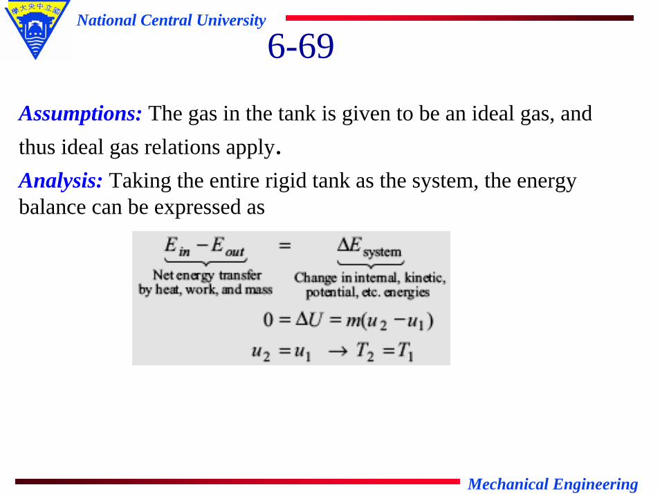
6-69An insulated rigid tank is divided into two equal parts by
a partition. Initially, one part contains 5 kmol of an ideal gas at 400 kPa and 500C, and the other side is evacuated. The partition is now removed, and the gas fills the entire tank. Determine the total entropy change during this process.
Mechanical Engineering
National Central University
6-69
Assumptions: The gas in the tank is given to be an ideal gas, and thus ideal gas relations apply.Analysis: Taking the entire rigid tank as the system, the energy balance can be expressed as

Mechanical Engineering
National Central University
6-69since u = u(T) for an ideal gas. Then the entropy change of the
gas becomes
This also represents the total entropy change since the tank doesnot contain anything else, and there are no interactions with the surroundings.
Mechanical Engineering
National Central University
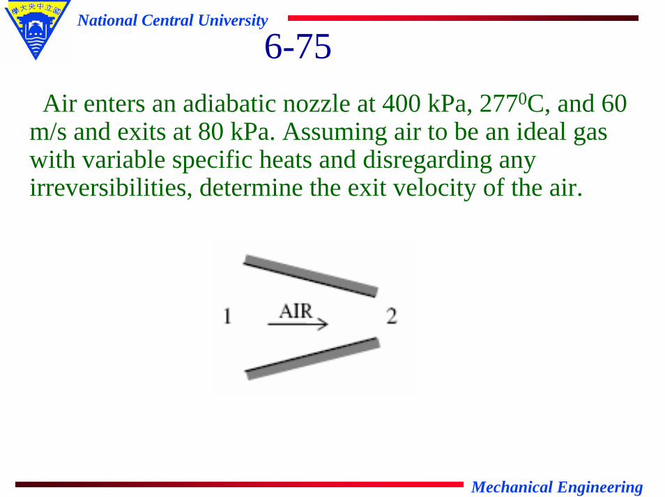
6-75Air enters an adiabatic nozzle at 400 kPa, 2770C, and 60
m/s and exits at 80 kPa. Assuming air to be an ideal gas with variable specific heats and disregarding any irreversibilities, determine the exit velocity of the air.

Mechanical Engineering
National Central University
6-75Assumptions: 1 Air is an ideal gas with variable specific heats. 2 The process is given to be reversible and adiabatic, and thus isentropic. Therefore, isentropic relations of ideal gases apply. 3 The nozzle operates steadily.Analysis: Assuming variable specific heats, the inlet and exit properties are determined to be (Table A-17)
and

Mechanical Engineering
National Central University
6-75We take the nozzle as the system, which is a control volume. The
energy balance for this steady-flow system can be expressed in the rate form as
Therefore,
Mechanical Engineering
National Central University
66--7979The turbines in steam power plants operate
essentially under adiabatic conditions. A plant engineer suggests to end this practice. She proposes to run cooling water through the outer surface of the casing to cool the steam as it flows through the turbine. This way, she reasons, the entropy of the steam will decrease, the performance of the turbine will improve, and as a result the work output of the turbine will increase. How would you evaluate this proposal?
Ans: Cooling the steam as it expands in a turbine will reduce its specific volume, and thus decrease the workoutput of the turbine. Therefore, this is not a good proposal.

Mechanical Engineering
National Central University
output work themaximize toprocessexpansion afor v input work theminimize toprocessn compressio afor v
Therefore,w v
vdPw
rev
2
1rev
↑
↓
↑⇒↑
−= ∫

Mechanical Engineering
National Central University
6-87Helium gas is compressed from 100 kPa and 200C to 857
kPa at a rate of 0.14 m3/s. Determine the power input to the compressor, assuming the compression process to be (a) isentropic, (b) polytropic with n=1.2, (c) isothermal, and (d) ideal two-stage polytropic with n=1.2

Mechanical Engineering
National Central University
6-87Assumptions: 1 Helium is an ideal gas with constant specific heats. 2 The process is reversible. 3 Kinetic and potential energy changes are negligible.Properties: The gas constant of helium is R = 2.0769 kJ/kg.K(Table A-1). The specific heat ratio of helium is k = 1.667.Analysis: The mass flow rate of helium is
(a) Isentropic compression with k = 1.667:

Mechanical Engineering
National Central University
6-87
(b) Polytropic compression with n = 1.2:
(c) Isothermal compression:

Mechanical Engineering
National Central University
6-87
(d) Ideal two-stage compression with intercooling (n = 1.2): In this case, the pressure ratio across each stage is the same, and its value is determined from
The compressor work across each stage is also the same, thus total compressor work is twice the compression work for a single stage:

Mechanical Engineering
National Central University
66--9393
Ans: No, because the isentropic process is not the model or ideal process for compressors that are cooled intentionally.
Is the isentropic process a suitable model for compressors that are cooled intentionally? Explain.

Mechanical Engineering
National Central University
6-97Steam enters an adiabatic turbine at 6 MPa, 6000C, and
80 m/s and leaves at 50 kPa, 1000C, and 140 m/s. If the power output of the turbine is 8 MW, determine (a) the mass flow rate of the steam flowing through the turbine and (b) the isentropic efficiency of the turbine.

Mechanical Engineering
National Central University
6-97Assumptions: 1 This is a steady-flow process since there is no change with time. 2 Potential energy changes are negligible. 3 The device is adiabatic and thus heat transfer is negligible.Analysis: (a) From the steam tables (Tables A-4 and A-6),
There is only one inlet and one exit, and thus . We take the actual turbine as the system, which is a control volumesince mass crosses the boundary. The energy balance for this steady-flow system can be expressed in the rate form as

Mechanical Engineering
National Central University
6-97
Substituting, the mass flow rate of the steam is determined to be

Mechanical Engineering
National Central University
6-97(b) The isentropic exit enthalpy of the steam and the power outputof the isentropic turbine are
and
Then the isentropic efficiency of the turbine becomes

Mechanical Engineering
National Central University
6-102Air enters an adiabatic compressor at 100 kPa and 170C
at a rate of 2.4 m3/s, and it exits at 2570C. The compressor has an isentropic efficiency of 84 percent. Neglecting the change in kinetic and potential energies, determine (a) the exit pressure of air and (b) the power required to drive the compressor.
Mechanical Engineering
National Central University
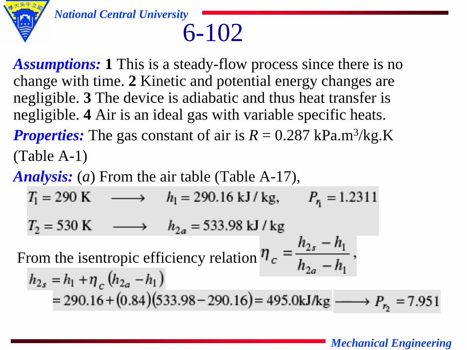
6-102Assumptions: 1 This is a steady-flow process since there is no change with time. 2 Kinetic and potential energy changes are negligible. 3 The device is adiabatic and thus heat transfer is negligible. 4 Air is an ideal gas with variable specific heats.Properties: The gas constant of air is R = 0.287 kPa.m3/kg.K (Table A-1)Analysis: (a) From the air table (Table A-17),
From the isentropic efficiency relation

Mechanical Engineering
National Central University
6-102Then from the isentropic relation ,
(b) There is only one inlet and one exit, and thus . We take the actual compressor as the system, which is a control volume since mass crosses the boundary. The energy balance for this steady-flow system can be expressed as

Mechanical Engineering
National Central University
6-102
where
Then the power input to the compressor is determined to be
Mechanical Engineering
National Central University
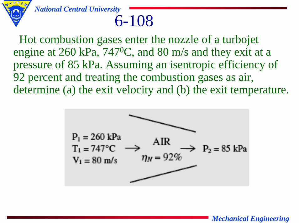
6-108Hot combustion gases enter the nozzle of a turbojet
engine at 260 kPa, 7470C, and 80 m/s and they exit at a pressure of 85 kPa. Assuming an isentropic efficiency of 92 percent and treating the combustion gases as air, determine (a) the exit velocity and (b) the exit temperature.

Mechanical Engineering
National Central University
6-108Assumptions: 1 This is a steady-flow process since there is no change with time. 2 Potential energy changes are negligible. 3 The device is adiabatic and thus heat transfer is negligible. 4 Combustion gases can be treated as air that is an ideal gas withvariable specific heats.Analysis: From the air table (Table A-17),
From the isentropic relation ,

Mechanical Engineering
National Central University
6-108There is only one inlet and one exit, and thus .We
take the nozzle as the system, which is a control volume since mass crosses the boundary. The energy balance for this steady-flow system for the isentropic process can be expressed as

Mechanical Engineering
National Central University
Then the isentropic exit velocity becomes
Therefore,
The exit temperature of air is determined from the steady-flow energy equation,
From the air table we read T2a = 786.3 K

Mechanical Engineering
National Central University6-115
Air (Cp=1.005 kJ/kg 0C) is to be preheated by hot exhaust gases in a cross-flow heat exchanger before it enters the furnace. Air enters the heat exchanger at 95 kPaand 200C at a rate of 1.6 m3/s. The combustion gases (Cp=1.10 kJ/kg 0C) enters at 1800C at a rate of 2.2 kg/s. and leave at 950C. Determine the rate of heat transfer to the air, the outlet temperature of the air, and the rate of entropy generation.

Mechanical Engineering
National Central University
6-115Assumptions: 1 Steady operating conditions exist. 2 The heat exchanger is well-insulated so that heat loss to the surroundings is negligible and thus heat transfer from the hot fluid is equal to the heat transfer to the cold fluid. 3 Changes in the kinetic and potential energies of fluid streams are negligible. 4 Fluid properties are constant.Properties: The specific heats of air and combustion gases are given to be 1.005 and 1.10 kJ/kg.°C, respectively. The gas constant of air is R = 0.287 kJ/kg.K (Table A-1).Analysis: We take the exhaust pipes as the system, which is a control volume.
Mechanical Engineering
National Central University
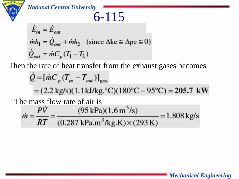
6-115
Then the rate of heat transfer from the exhaust gases becomes
The mass flow rate of air is
Mechanical Engineering
National Central University
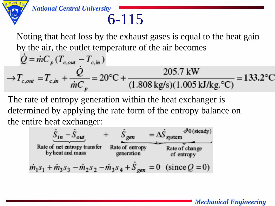
6-115Noting that heat loss by the exhaust gases is equal to the heat gain by the air, the outlet temperature of the air becomes
The rate of entropy generation within the heat exchanger is determined by applying the rate form of the entropy balance on the entire heat exchanger:

Mechanical Engineering
National Central University
6-115
Then the rate of entropy generation is determined to be

Mechanical Engineering
National Central University
6-126For heat transfer purposes, a standing man can be modeled as a 30-cm diameter, 170-cm long vertical cylinder with both the top and bottom surfaces insulated and with the side surface at an average temperature of 340C. If the rate of heat loss from this man to environment at 200C is 336W, determine the rate of entropy transfer from the body of this person accompanying heat transfer, in W/K.

Mechanical Engineering
National Central University
6-126Assumptions: Steady operating conditions exist.Analysis: Noting that Q/T represents entropy transfer with heat, the rate of entropy transfer from the body of the person accompanying heat transfer is

Mechanical Engineering
National Central University
6-131A hot-water stream at 700C enters an adiabatic mixing
chamber with a mass flow rate of 3.6 kg/s, where it is mixed with a stream of cold water at 200C. If the mixture leaves the chamber at 420C, determine (a) the mass flow rate of the cold water and (b) the rate of entropy generation during this adiabatic mixing process. Assume all the streams are at a pressure of 200 kPa.

Mechanical Engineering
National Central University
6-131Assumptions: 1 Steady operating conditions exist. 2 The mixing chamber is well-insulated so that heat loss to the surroundings is negligible. 3 Changes in the kinetic and potential energies of fluid streams are negligible.Properties: Noting that T < Tsat @ 200 kPa = 120.23°C, the water in all three streams exists as a compressed liquid, which can be approximated as a saturated liquid at the given temperature. Thus from Table A-4,

Mechanical Engineering
National Central University
6-131
Analysis: (a) We take the mixing chamber as the system, which is a control volume. The mass and energy balances for this steady-flow system can be expressed in the rate form as

Mechanical Engineering
National Central University
6-131Combining the two relations gives
Solving for and substituting, the mass flow rate of cold water stream is determined to be
Also,(b) Noting that the mixing chamber is adiabatic and thus there is no heat transfer to the surroundings, the entropy balance of thesteady-flow system (the mixing chamber) can be expressed a

Mechanical Engineering
National Central University
6-131
Substituting, the total rate of entropy generation during this process becomes
Mechanical Engineering
National Central University
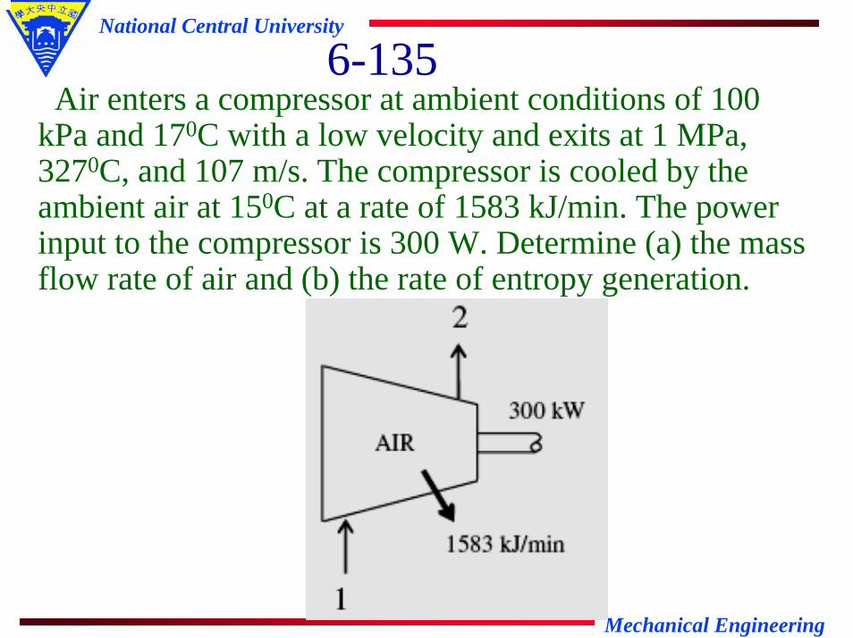
6-135Air enters a compressor at ambient conditions of 100
kPa and 170C with a low velocity and exits at 1 MPa, 3270C, and 107 m/s. The compressor is cooled by the ambient air at 150C at a rate of 1583 kJ/min. The power input to the compressor is 300 W. Determine (a) the mass flow rate of air and (b) the rate of entropy generation.

Mechanical Engineering
National Central University
6-135Assumptions: 1 This is a steady-flow process since there is no change with time. 2 Potential energy changes are negligible. 3 Air is an ideal gas with variable specific heats.Properties: The inlet and exit enthalpies of air are (Table A-17)
Analysis: (a) We take the compressor as the system, which is a control volume since mass crosses the boundary. The energy balance for this steady-flow system can be expressed in the rate form as

Mechanical Engineering
National Central University
6-135
Substituting, the mass flow rate is determined to beThus,
Mechanical Engineering
National Central University
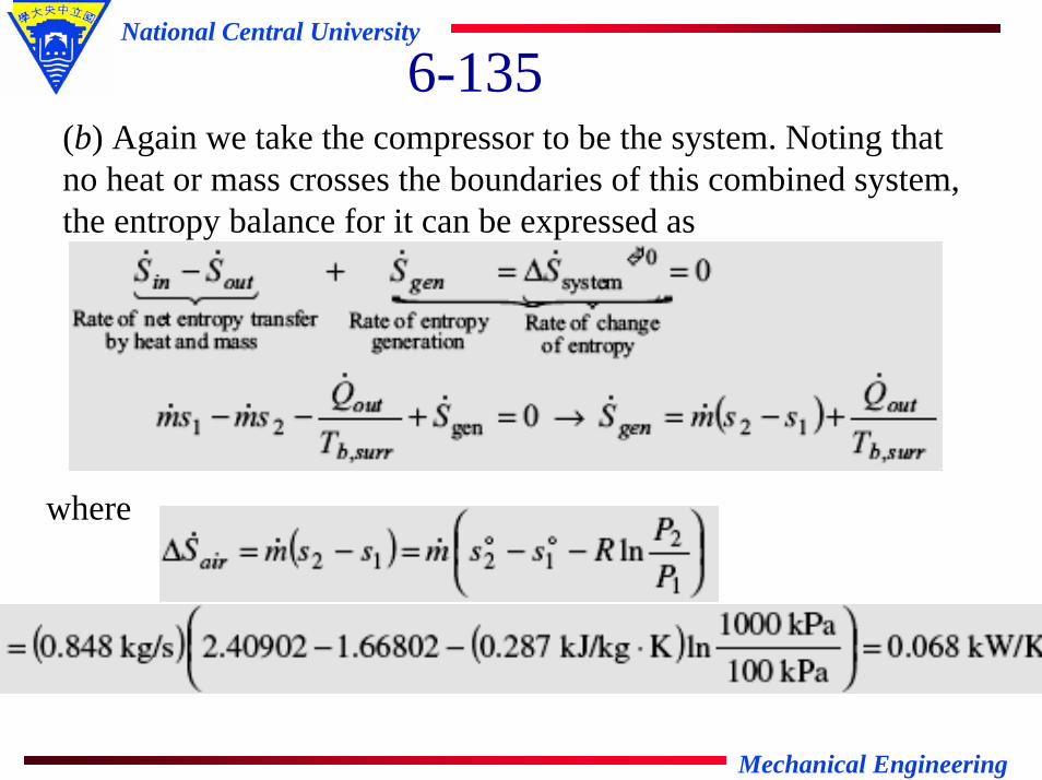
6-135(b) Again we take the compressor to be the system. Noting that no heat or mass crosses the boundaries of this combined system, the entropy balance for it can be expressed as
where

Mechanical Engineering
National Central University
6-135Substituting, the rate of entropy generation during this process
is determined to be

Mechanical Engineering
National Central University
6-150One ton of liquid water at 800C is brought into a well-
insulated and well-sealed 4-m *5-m *6-m room initially at 220C and 100 kPa. Assuming constant specific heats for both air and water at room temperature, determine (a) the final equilibrium temperature in the room and (b) the total entropy change during this process, in kJ/K.

Mechanical Engineering
National Central University
6-150Assumptions: 1 The room is well insulated and well sealed. 2 The thermal properties of water and air are constant at room temperature. 3 The system is stationary and thus the kinetic and potential energy changes are zero. 4 There are no work interactions involved.Properties: The gas constant of air is R = 0.287 kPa.m3/kg.K (Table A-1). The specific heat of water at room temperature is C = 4.18 kJ/kg⋅°C (Table A-3). For air is Cv = 0.718 kJ/kg⋅°C at room temperature.Analysis: The volume and the mass of the air in the room are

Mechanical Engineering
National Central University
6-150Taking the contents of the room, including the water, as our
system, the energy balance can be written as
Substituting,
It gives the final equilibrium temperature in the room to be
Tf = 78.6°C

Mechanical Engineering
National Central University
6-150(b) Considering that the system is well-insulated and no mass is
entering and leaving, the total entropy change during this process is the sum of the entropy changes of water and the room air,
where

Mechanical Engineering
National Central University
6-150
Substituting, the total entropy change is determined to be
∆Stotal = 17.86 - 16.61 = 1.25 kJ/K