!['ZKD < U í õ o ] î ì î ì · î õ í ìdhD/BKt/ ^ Ç o Á ] < î ì Z > ò ð r^dK ð ò ì ñ ì ì õ ò ì X ì ì ï ñ í ì< D Z < t } v ] l < î ì](https://static.fdocuments.in/doc/165x107/5f67527405909476d76ae24d/zkd-u-o-dhdbkt-o-z-.jpg)
Entron Controls, LLC. í ð ì î S. Batesville Road Greer, SC...
24
700230 Rev 1.0 Entron Controls, LLC. 1402 S. Batesville Road Greer, SC 29650 Phone: 864.416.0190 fax: 864.416.0195 www.EntronControls.com
Transcript of Entron Controls, LLC. í ð ì î S. Batesville Road Greer, SC...

700230 Rev 1.0
Entron Controls, LLC. 1402 S. Batesville Road
Greer, SC 29650 Phone: 864.416.0190
fax: 864.416.0195 www.EntronControls.com

2
700230 2 Rev 1.0
READ THIS MANUAL COMPLETELY BEFORE ATTEMPTING TO INSTALL OR OPERATE THE CONTROL.
STORE THIS TECHNICAL INFORMATION IN A PLACE TO WHICH ALL USERS HAVE ACCESS AT ANY TIME
ENTRON Controls follows the practices of the RWMA for precautionary labeling. See RWMA Bulle-tins #1 and #5 for a complete description. Observe the WARNING, DANGER, and CAUTION labels affixed to control to maintain safe operation. ENTRON Controls, LLC. and its affiliates are not re-sponsible for any harm caused by non-compliance of instructions associated with the aforemen-tioned labels or signal words to follow.
The signal word DANGER is used to call attention to immediate or imminent hazards which if not avoided will result in immediate, serious, or personal injury or loss of life. Examples are: exposed high voltage; exposed fan blades.
The signal word WARNING is used to call attention to potential hazards which could result in personal injury or loss of life. Examples are: not using proper personal protection; removal of guards.
The signal word CAUTION is used to call attention to hazards which could result in non-life threatening personal injury or damage to equipment. CAUTION may also be used to alert against unsafe practices.
The term NOTICE is used for making recommendations on use, supplementary information, or helpful suggestions. Non-compliance with these recommendations may result in damage to control, welding machine, or workpiece. ENTRON Controls, LLC. and its affiliates are not responsible for damage caused by such non-compliance, and warranties may be voided accordingly at the discre-tion of ENTRON Controls.
WARNING: Individuals with cardiac devices should maintain a safe distance due to strong magnetic fields arising from resistance welding. The function of cardiac pacemakers and defibrillators may be disturbed, which may cause death or considerable health damages to persons concerned! These persons should avoid the welding system unless authorized by a licensed physician.
Important Safety Instructions

3
700230 3 Rev 1.0
Filling out the following information (and keeping it readily available) may allow for future technical service of equipment to be conducted more efficiently:
Model #: EN6001
Serial #:
OEM/Distributer:
Contact #:
Purchase Date:
Hardware Connections P1—2, Foot Switch #1
P1—3, Foot Switch #2
P1—4, Emergency Stop
P1—5, No Weld Signal
P1—6, Programmable Input #1
P1—7, Programmable Input #2
P1—8, Programmable Input #3
P1—9, Programmable Input #4
P1—10, Programmable Input #5
P1—11, Programmable Input #6
P2—2, Solenoid Valve #1
P2—3, Solenoid Valve #2
P2—4, Solenoid Valve #3
P2—5, Programmable Output #1
P2—6, Programmable Output #2
P2—7, Programmable Output #3
P2—8, Programmable Output #4
P3 Sensing Coil
My Control Information
Primary Secondary Not Used

4
700230 4 Rev 1.0
Filling out the following information (and keeping it readily available) may allow for future technical service of equipment to
be conducted more efficiently. Please duplicate and complete this page for each utilized schedule:
SCHEDULE #:
Squeeze Delay: cycles KVA or %
Squeeze: cycles Valves:
Weld 1: cycles KVA or %
Cool 1: cycles
Slope: cycles
Weld 2: cycles KVA or %
Cool 2: cycles
Impulses: cycles
Hold: cycles
Off: cycles
Cycle Mode:
Comments:
Tap Setting: Pressure: Machine:
Weld Schedule Worksheet

5
700230 5 Rev 1.0
Functions ………………………................................................................. 6
Specifications ……….……………………………………………………... 7
Wiring Diagrams .....................................................………………………. 8
Menu Navigation ....................................................................................... 9
Saving Weld Schedules ……..……………………………………………….. 10
Loading Weld Schedules ……..……………………………………………….. 11
Updating Firmware ………………………………………………………………. 12
User Connections ………………………………………………………………. 13
Weld Timing Cycles .…………………………….………………………… 14
Programming Parameters List .………………………………….…………… 15
I/O Map ……………………………………………………………………….. 22
Error List ……………………………………………………………………….. 23
Warranty and Service Policy …………………………………….…………. 24
Table of Contents

6
700230 6 Rev 1.0
Constant current regulation
Primary or Secondary feedback
Current Monitoring with high, low, and pre-limits
Up to 64 programs (internal or external selection)
On Timer Membrane Keyboard with backlit 128x64 (8 lines) LCD graphic display
Six (6) inputs and four (4) outputs with output protection on CPU
Electrode management functions; including stepping, current counting, tip-dressing, and preset
curves
Welding programs may be linked together for complex spot schedules (chained or successive)
USB-capable firmware refresh
AC 60/50 Hz welding support
Spot / Pulsation / Seam welding / Flash or Butt welding / Brazing
Multiple weld intervals plus pulsation, upslope and downslope
Air-over-oil gun operation
Water Saver (contactor timer)
Head lock function
Program lockout (key switch) function
Operation mode switch (program lockout and Weld/No Weld)
Error reset switch
Optional plug-in Ethernet card provides PLC compatibility with Modbus and EtherNet/IP
Functions

7
700230 7 Rev 1.0
Environmental Conditions: Operating Temperature 0°C to 60°C Storage/Transport Temperature -25°C to 70°C Air pressure 0 to 2000m above sea level Humidity no dew point excursion allowed Enclosure Ratings NEMA 1 and NEMA 12 Electronics Ratings: CPU operating voltage (without I/O) 24 VDC +5% at 220 mA Rated current (without I/O) at 24V SV1-SV3: ~500 mA PO1-PO4: ~500 mA Discrete I/O: Input +24V +15% DC Output 24 VDC, 0.5A max AC Output 120 VAC, 1A max Supply I/O: 24 VDC +5%
Specifications

8
700230 8 Rev 1.0
Wiring and Connectivity

9
700230 9 Rev 1.0
Status Page List (Default)
Main Menu
1. Use Schedule
2. Edit Schedule
3. Copy Schedule
4. Reset Error
5. Edit counter
6. About
AND
Setup Menu
Menu Navigation
Schedule Select

10
700230 10 Rev 1.0
Step 1: Insert a formatted USB drive into USB port on the
control panel
Step 2: From the ‘Setup Menu’ (see Menu Navigation for de-
tails) select “Utility”.
Step 3: Select “Backup data”
Step 4: Rename file (desired) using and
Step 5: Set “Confirm” to “YES” using and
Step 6: Press and verify that “DONE!!!” appears in the
top left corner of the title bar.
Saving Weld Schedules

11
700230 11 Rev 1.0
Step 1: Insert USB drive with a previously saved backup file*
into the USB port on the control panel.
Step 2: From the ‘Setup Menu’ (see Menu Navigation for de-
tails) select “Utility”.
Step 3: Select “Restore data”
Step 4: Select the desired filename* using and
Step 5: Set “Confirm” to “YES” using and
Step 6: Press and verify that “DONE!!!” appears in the
top left corner of the title bar.
*Note: The backup file must be on the root directory of the
USB drive. And the filename must be
EN600100.EN6 to EN600199.EN6
Loading Weld Schedules
12
700230 12 Rev 1.0
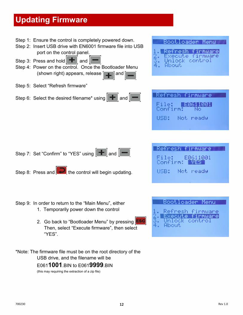
Step 1: Ensure the control is completely powered down.
Step 2: Insert USB drive with EN6001 firmware file into USB
port on the control panel. Step 3: Press and hold and
Step 4: Power on the control. Once the Bootloader Menu
(shown right) appears, release and
Step 5: Select “Refresh firmware”
Step 6: Select the desired filename* using and
Step 7: Set “Confirm” to “YES” using and
Step 8: Press and the control will begin updating.
Step 9: In order to return to the “Main Menu”, either
1. Temporarily power down the control
2. Go back to “Bootloader Menu” by pressing
Then, select “Execute firmware”, then select
“YES”.
*Note: The firmware file must be on the root directory of the
USB drive, and the filename will be
E0611001.BIN to E0619999.BIN (this may requiring the extraction of a zip file)
Updating Firmware

13
700230 13 Rev 1.0
User Connections
Port Designation Switch
P1—1 Foot Switch Common 24VDC
P1—2 Foot Switch #1 N.O.
P1—3 Foot Switch #2 N.O.
P1—4 Emergency Stop N.C.
P1—5 No Weld Signal N.C.
P1—6 Programmable Input #1 N.O.
P1—7 Programmable Input #2 N.O.
P1—8 Programmable Input #3 N.O.
P1—9 Programmable Input #4 N.O.
P1—10 Programmable Input #5 N.O.
P1—11 Programmable Input #6 N.O.
P1—12 Foot Switch Common 24VDC
P2—1 Solenoid Valve Common 0VDC
P2—2 Solenoid Valve #1 24V Digital
P2—3 Solenoid Valve #2 24V Digital
P2—4 Solenoid Valve #3 24V Digital
P2—5 Programmable Output #1 24V Digital
P2—6 Programmable Output #2 24V Digital
P2—7 Programmable Output #3 24V Digital
P2—8 Programmable Output #4 24V Digital

14
700230 14 Rev 1.0
Weld Timing Cycle
PARAMETER SETTING
Squeeze Delay 0 cycles
Squeeze 3 cycles
Weld 1 0 cycles
Cool 1 0 cycles
Slope 0 cycles
Weld 2 2 cycles
>Mode Phase Shift
>Heat 50 %
Cool 2 1 cycle
Hold 2 cycles
Off 2 cycles
Impulses 2 cycles
The diagram above is intended to demonstrate a resulting weld-
ing timing cycle using the attached parameters; it is not recom-
mended as part of a functional weld schedule.
Pressure Curve
Squeeze (3 cycles)
Weld 2 (2 cycles)
Hold (2 cycles)
Weld 2 Cool 2 (1 cycle)
~50% Phase Shift
Cool 2 Off (2 cycles)
First Impulse Second Impulse Sequence
Initiation
Sequence
Termination

15
700230 15 Rev 1.0
Parameter List
Sub Menu Parameter Input Range Description
1. Use Schedule
Schedule [0-63] Default = 0
2. Edit Schedule
Advance [0-99] cycles Default = 0 This option only appears when ‘air-over-oil’ configuration is selected.
Intensify [0-99] cycles Default = 0 This option only appears when ‘air-over-oil’ configuration is selected.
Block Delay [0-99] cycles Default = 0 This option only appears when ‘air-over-oil’ configuration is selected.
Schedule Number [0-63]
Default = 0 In order to accept changes made to any field, the button must pressed. It is important to make sure that the correct schedule number is selected AND accepted BEFORE completing all of the corresponding settings to follow.
Squeeze Delay [0-99] cycles
Default = 0 Additional time delay to be added to 'Squeeze'. This is usu-ally utilized when 'Cycle Mode' is set to repeat. The squeeze delay will only be applied to the first weld of the repeating cycle.
Squeeze [0-99] cycles Default = 0 Time delay between the signal to the programmed valve(s) and weld initiation.
>Valve
None 1 2 3
1+2 1+3 2+3 1+2+3
Default = None Selection of valve(s) to be activated
Weld 1 [0-99] cycles Default = 0 Also referred to as "pre-heat"
>Mode Phase Shift
Const Current Default = Phase Shift
>Heat [0-99] % Phase shift %; does not apply when ‘Mode’ is set to Const Current
or
>Current [0.00-60.00] kA Weld current setting does not apply when Mode is set to Phase Shift
>I1 Monitor On Off
Default = Off Must be enabled in order to track/report current errors
>PW1 Monitor On Off
Default = Off Must be enabled in order to track/report phase shift abnor-malities.
Cool 1 [0-99] cycles Default = 0 Time delay between ‘Weld 1’ and ‘Weld 2’. Designed to give an impulse effect.
Main Menu

16
700230 16 Rev 1.0
Parameter List
Sub Menu Parameter Input Range Description
2. Edit Schedule (continued)
Slope [0-99] cycles
Default = 0 The number of additional cycles between 'Weld 1' and 'Weld 2' in order to transition between the two gradually. A larger 'Weld 1' will result in a downslope; whereas a larger 'Weld 2' will result in an upslope.
Weld 2 [0-99] cycles Default = 0
>Mode Phase Shift
Const Current Default = Phase Shift
>Heat [0-99] % Phase shift %; does not apply when '>Mode' is set to Const Current
or
>Current [0.00-60.00] kA Weld current setting does not apply when Mode is set to Phase Shift
>I2 Monitor On Off
Default = Off Must be enabled in order to track/report current errors
>PW2 Monitor On Off
Default = Off Must be enabled in order to track/report phase shift abnor-malities.
Cool 2 [0-99] cycles Default = 0 Primarily used when applying multiple impulses; time delay following each 'Weld 2' impulse.
Hold [0-99] cycles Default = 0 Time delay during which the electrodes remain in contact with the part being welded to allow weld nugget to congeal.
Off [0-99] cycles
Default = 0 Time delay following 'Hold' cycle in which the valve(s) re-lease; the next schedule/sequence will not begin until the 'Off' cycle is complete.
Impulses [1-99] cycles Default = 1 Number of times to deliver Weld 2, Cool 2. (Impulses do NOT apply to Weld 1, Cool 1)
I offset -1 % 0 %
+1 %
Default = 0 Adjustable increase or decrease to total current delivered by a sequence. This is one of the few adjustable parameters when control is locked. Parameter is only visible when 'Max I offset' is not "0".
>Change all No Yes
Default = No No – 'I offset' will be applied to the current schedule Yes – 'I offset' will be applied to all schedules'
Block Delay [0-99] cycles Default = 0 This option only appears when ‘air-over-oil’ configuration is selected.
Main Menu (continued)

17
700230 17 Rev 1.0
Parameter List
Sub Menu Parameter Input Range Description
2. Edit Schedule (continued)
Cycle Mode
Non-Repeat Repeat
Chained Successive Wait Here
Default = Non-Repeat Non-repeat – Control can be initiated for only one sequence/schedule even if initiation remains closed. Repeat – Sequences/ schedules will continue if initiation re-mains closed. Chained – Schedules are chained together so that consecu-tive schedules can be sequenced from one initiation. Successive – Schedules are chained together so that consecu-tive schedules will be sequenced from separate initiations. Wait-Here – only applies when 'Weld2' is set to 99 cycles. This allows infinite Weld 2 duration until Escape is trig-
3. Copy Schedule
Copy From [0-63] Schedule # to be copied
Copy To [0-63] Schedule # to be replaced
Confirm Yes No
Must select "Yes" and press the key to complete the above copy/replace. "DONE!!!" will appear in the title bar once complete.
4. Reset Error
Confirm Yes No
Must select "Yes" and press the key to complete the above copy/replace. "DONE!!!" will appear in the title bar once complete.
5. Edit Counter
Counter Enable Disable
Default = Disable Enable – 'Weld count done' will increment with each weld delivered. Error "ER25" will be reported when 'Max part count' = 'Part count done'
Max part Count [0-60,000] Default = 60,000 Number at which the 'part count done' reports error "ER25"
Weld per part [1-9,999] Default = 1 The number of welds to increment 'part count done' by one.
RST Counter
None PCTR WCTR Both
Default = None Resets counter PCTR – part counter WCTR – weld counter
Main Menu (continued)

18
700230 18 Rev 1.0
Parameter List
Setup Menu
Sub Menu Parameter Input Range Description
1. Config
Weld Mode Spot
Seam1 Seam2
Default = Spot Spot – Standard squeeze, weld, hold and off sequence. Seam1 – When FS1 or FS2 input is toggled, control will run 'schedule' from 'Squeeze Delay' through 'Cool 2'. If FS1 or FS2 input is held, control will repeat 'Weld 2' and 'Cool 2'. Seam2–FS1 initiation implements same function as in Seam1. FS2, schedule 20, schedule 40 and schedule 60 will always initiate "Spot" Weld Mode
Retraction Off
Maintained Momentary
Default = Off Maintained – Retraction output directly reflects retraction input Momentary – Retraction output changes state with an im-pulse of retraction input. This parameter is ignored if 'Beat_Mode' is enabled.
On Error Continue
Head Lock Stop
Default = Continue Continue – Further welds are permitted regardless of previ-ous weld status Head Lock – On error, valve signal(s) are held on. Addi-tional welds are not permitted until Error Reset occurs. Stop – On error, valve signal(s) turn off as normal. Addi-tional welds are not permitted until Error Reset occurs.
Sch Select Internal External
Default = Internal Internal – FS1 will initiate the programmed weld schedule number External – FS1 will initiate the weld schedule number ac-cording to the binary value represented by PI3, PI4, PI5, and PI6. (FS2 will always initiate weld schedule 20.)
I-Feedback Primary
Secondary
Default = Secondary This setting should correspond to the physical location of the sensing coil.
Air-over-oil Off
Mode 1 Mode 2
Default = Off Mode 1: air-over-oil setting without retraction Mode 2: air-over-oil setting with retraction enabled using 'Retract Open' and 'Retract Close' settings
Retract Open [0-99] cycles
Default = 0 Time delay to allow for retraction from "pre-weld" position to "fully open" position Sub Menu only appears when 'air-over-oil' is set to "Mode 2"
Retract Close [0-99] cycles
Default = 0 Time delay to allow for closure from "fully open" position to "pre-weld" position Sub Menu only appears when 'air-over-oil' is set to "Mode 2"

19
700230 19 Rev 1.0
Parameter List
Setup Menu (continued)
Sub Menu Parameter Input Range Description
1. Config
(continued)
Beat mode
Off Squeeze
Sqz. + Weld Wait-Here
Default = Off Off – Sequence/Schedule will complete with a momentary activation of FS1 or FS2 Squeeze – Sequence/Schedule requires continuous activation of FS1 or FS2 until the squeeze sequence is complete, other-wise the sequence will terminate. Sqz. + Weld – Welding sequence requires continuous activa-tion of FS1 or FS2 until the weld sequence is complete, oth-erwise the sequence will terminate. Wait-Here – Welding sequence requires continuous activa-tion of FS1 or FS2 until the weld sequence is complete, oth-erwise the sequence will temporarily pause (retraction will not occur). This setting requires the active schedule's 'Cycle Mode' to also be set to "Wait-Here".
AVC Disabled
Max [1-10] %
Default = Disabled Automatic Voltage Compensation – Will add additional per-centage to phase shift in order to compensate for diminished supply voltage. (only works with schedules using "Phase Shift" Mode to regulate current)
AVC nom. [187-633] volts Default = 480 Supply voltage on which the control is designed to operate. Parameter is only visible when 'AVC' is enabled.
Voltage monitor Off On
Default = Off On – High and Low Voltage errors are enabled using the following parameters.
>High [160-690] volts
Default = 690 Error "ER23" will be triggered if supply voltage is above the set value Parameter is only visible when 'Voltage Monitor' is "On"
>Low [160-690] volts
Default = 160 Error "ER24" will be triggered if supply voltage is below the set value Parameter is only visible when 'Voltage Monitor' is "On"
Max I offset [0-15] % Determines the input range for 'I offset' parameter. For ex-ample, if 'Max I offset' is 6%, 'I offset' input range is -6% to +6%
Water Saver [0-199] sec Default = 0 Time duration that the water flow signal will remain on fol-lowing a weld.
87° delay Off On
Default = Off On – The first half cycle is delayed 87degrees (51.6% max) phase shift in order to minimize saturation of the weld trans-former
Half Cycle
Off + -
AC
Default = Off + – Only the positive half cycle is output - – Only the positive half cycle is output AC – Alternating positive/negative half cycles are output

20
700230 20 Rev 1.0
Parameter List
Setup Menu (continued)
Sub Menu Parameter Input Range Description
1. Config
(continued)
Power factor [0-99] %
Default = 75
0 – "Automatic Power Factor" mode
1-99 – Manual power factor delay. Value must be deter-
mined by the Power Factor Delay and will vary for each ma-
chine.
If a primary or secondary coil is NOT installed, a manual
power factor of 80% is recommended. Automatic Power
Factor may react abnormally if enabled without a coil.
Blanking [0-99] cycles
Default = 0
The number of weld cycles to exclude from measurement
and limit testing
Display return [0-10] min
Default = 0
0 – Disabled
Length of time before the display returns to 'Status Page 1'
Clear
None
I/O Map
Calibration
Config
Stepper
Counter
Schedule
All
Clearing data from this menu does not require a confirma-
tion. "DONE!!!" will appear in the title bar as verification.
2. Calibration
Toroid [135-165] mV/kA Default = 150
For accurate current monitoring
Max I [20-60] kA Default = 20
AC line scale [0.8-1.2] Default = 1.0
For accurate voltage monitoring
3. I/O Map (see page 21)
4. Error Map (see page 22)
5. Stepper
Stepper Disable
Heat
Default = Disable
Heat – Stepper function enabled with current compensation
Tip dress [0-9,999] Default = 9,000
When ’Count Done’=’Tip dress’, error (ER31) will trigger
RST stepper No
Yes
Selecting "Yes" and pressing the key will reset the
‘Count done’ to zero

21
700230 21 Rev 1.0
Parameter List
Setup Menu (continued)
Sub Menu Parameter Input Range Description
5. Stepper
(continued)
[01-10]:Count [0-9,999] Default = 0 The number of welds required to move onto the next step
>Heat+ [0-99] %
Default = 0 Additional phase shift to be added to Weld 1 and Weld 2 ‘Heat’ settings Only applies when the weld ‘Mode’ is set to “Phase Shift.”
>Current+ [0.00-99.99] kA
Default = 0 Additional current to be added to Weld 1 and Weld 2 ‘Current’ settings Only applies when the weld ‘Mode’ is set to “Const Cur-rent.”
6. Utility
Backup Data (see page 10)
Restore Data (see page 11)

22
700230 22 Rev 1.0
I/O Map
Setup Menu (continued)
Input/Output Options Description
PI1
TT1 2nd stage Back step
PCTR
TT1 – Temperature Limit Switch (also called TLS) 2nd stage – For valve closure before squeeze; to ensure good electrode position Back step – Return to previous schedule in “Successive” Cycle mode PCTR – Part counter reset
PI2
Edit lock PS1
Interlock WCTR Reset
Edit lock – closed = control locked; open = control unlocked PS1 – Pressure switch signal Interlock – Signal to authorize weld; used with PO4 Interlock WCTR – Weld counter reset
PI3
Error reset Sch. Select 1 Stepper reset
2nd Stage
Error reset – Clear error in order resume function Sch. Select 1 – Binary value of “one” for externally selecting schedule Stepper reset – Return stepper to “Zero” position 2nd stage – For valve closure before squeeze; to ensure good electrode position
PI4
Interlock Sch. Select 2 Error Reset (Not Used)
Interlock – Signal to authorize weld; used with PO4 Interlock Sch. Select 2 – Binary value of “two” for externally selecting schedule Error reset – clears error in order resume function
PI5
Back step Sch. Select 4
Retraction (Not Used)
Back step – Return to previous schedule in “Successive” Cycle mode Sch. Select 4 – Binary value of “four” for externally selecting schedule Retraction – Retract input command for release of valves
PI6
Stepper Reset Sch. Select 8
Edit lock Escape
Stepper reset – Return stepper to “Zero” position Sch. Select 8 – Binary value of “eight” for externally selecting schedule Edit lock – closed = control locked; open = control unlocked Escape – command to escape current weld schedule/sequence
PO1
Any Error Retraction Force Error Major Error
Any Error – Major or minor error is detected Retract Output – Command to retract (in addition to programmed valves) Force Error – Pressure switch is not detecting proper electrode force Major Error – Major error detected; determined by “Error Map” settings
PO2
AVC Error Contactor Error
Step End EOS
AVC Error – Automated Voltage Compensation is insufficient Contactor Error – Energy is being shunted; (typically set to trip a breaker) Step End – Programmable step has completed its count EOS – 0.5sec signal at the end of each weld sequence
PO3
Current Error Any Error Count end
Water Saver
Current Error – Constant Current Control in insufficiently compensating Any Error – Major or minor error is detected Count end – ‘Max part count’ has been reached Water Saver – signal turns off after a set time following the last weld
PO4
Step End Current Error AVC Error Interlock
Step End – Programmable step has completed its count Current Error – Constant Current Control in insufficiently compensating AVC Error – Automated Voltage Compensation is insufficient Interlock – “Request to weld” signal from external source; used with PI4

23
700230 23 Rev 1.0
Error List
# Name # Name 1 Config error 33 Starts/Retract @ RST
2 Calibration error 34 SYNC error
3 Schedule error 35 PNW error
4 Use Schedule error 36 DC Safety relay err.
5 37 AC Safety relay err.
6 Counter error 38
7 Stepper error 39
8 I/O Map error 40
9 E-stop error 41
10 TC1 error 42
11 P1-No weld 43 Pre-high current1
12 PS1 error 44 Pre-low current1
13 SCR short 45 Pre-high current2
14 2nd stage error 46 Pre-low current2
15 TT1 error 47
16 Interlock error 48
17 49
18 50
19 High current1 51
20 Low current1 52
21 High current2 53
22 Low current2 54
23 High voltage 55
24 Low voltage 56
25 Counter end 57 Retract open error
26 Stepper end 58
27 High PW1 59 Retract input closed
28 Low PW1 60 PS not ready
29 High PW2 61 Retract not ready
30 Low PW2 62 2nd stage not ready
31 Tip dress pre-warn 63
32 AVC error 64 Interlock not ready
Note: All error defaults are set to “Minor errors”. Error handling should be set under the configura-tions menu and by utilizing the “Any Error”, “Contactor Error”, and “Major Error” options available for the programmable outputs in the I/O Map.

24
700230 24 Rev 1.0
ENTRON takes great pride in offering its customers a quality product that is built to withstand numerous industrial conditions. The prod-ucts are built to last, and in return for customer loyalty, we offer a lim-ited warranty on all new control panels. ENTRON Controls, LLC., warrants that all ENTRON control panels except Mid-frequency Inverter controls, silicon controlled rectifiers (SCRs), insulated gate bipolar transistors (IGBTs), SCR and IGBT assemblies, circuit breakers, and electro-mechanical contactors, are free of manufacturing de-fects for a period of TWO YEARS from the date of original purchase and, in the event of a manufac-turing defect, ENTRON will repair or replace, at its discretion, the defective part without any cost for parts or labor. All SCRs, IGBTs, SCR and IGBT assemblies, circuit breakers, and electro-mechanical contactors in ENTRON control panels are covered by a limited warranty from the original manufacturer. If these parts fail because of a manufacturing defect, they will not be repaired or replaced by ENTRON, but will be returned by ENTRON to the original manufacturer in accordance with said manufacturer’s warranty. ENTRON Controls, LLC., warrants that all Mid-frequency Inverter controls are free of manufacturing defects for a period of ONE YEAR from the date of original purchase and, in the event of a manufac-turing defect, ENTRON will repair or replace, at its discretion, the defective part without any cost for parts or labor. To obtain repairs or replacement parts under this warranty, the defective part must be returned, pre-paid, to ENTRON Controls, LLC., 1402 S. Batesville Road, Greer, South Carolina 29650. Please send your repair to the attention of “Service” with a description of the problem you are experiencing, contact person and phone number. EXCLUSIONS: This warranty does not cover damage by accident or misuse, unauthorized re-pair or modification to any control assembly by the customer. The warranty period is considered from date of shipment and is tracked by ENTRON’s serial num-bering system. USE OF OUT OF WARRANTY REPAIR SERVICE: To obtain service for any printed circuit board assembly or welding control after the warranty period, send the assembly or control, prepaid, to ENTRON Controls, LLC., and ENTRON will repair the printed circuit board assembly or control and return it to you without further warranty. Additional service charges will be invoiced at time of shipment. Thank you for using ENTRON Controls.
Your ENTRON Controls, LLC., Original Equipment Manu-facturers (OEMs), Dealers and Distributors are your first response contact to secure technical assistance on control or welding problems. Should they be unable to assist you, please contact your ENTRON sales representative or the factory directly. Contact the factory at 864-416-0190.
Warranty and Service Policy
![D Ì î ì î ì v ] Z P Z o v OLHEH *HPHLQGHE UJHU /LHEH ... · D Ì î ì î ì v ] Z P Z o v Á v U } v v Á µ ( º v í ô X ñ X î ì î ì ] v µ ( v X](https://static.fdocuments.in/doc/165x107/5f082ece7e708231d420c034/d-oe-v-z-p-z-o-v-olheh-hphlqghe-ujhu-lheh-d-oe-v.jpg)
![spot registered list · 2020. 12. 14. · o v E }E u } u u µ v ] Ç î í ì ì ì í ìDh, DD /> Dh î í ì ì ì ð î ,/Z D E ^ î í ì ì ì ð ñ EE/ ZK^ d,KD ^ î í ì ì](https://static.fdocuments.in/doc/165x107/60bfa82743392f54e03262b4/spot-registered-list-2020-12-14-o-v-e-e-u-u-u-v-.jpg)

![d } d ] ] } v d ] ] } v^/ - JAZMP€¦ · d î ì î ì d } d ] ] } v d ] ] } v^/ d î ì î ì d } d ] ] } v d ] ] } v^](https://static.fdocuments.in/doc/165x107/60fa9e7864650c3b3a338d31/d-d-v-d-v-jazmp-d-d-d-v-d-v-d-.jpg)


![D ] µ u rd u D v P u v W o v î ì î ì r î ì î î](https://static.fdocuments.in/doc/165x107/62919e47f713036ca2502d94/d-u-rd-u-d-v-p-u-v-w-o-v-r-.jpg)
![E } ] ( } í Ç µ v î ì î í r î ì î î](https://static.fdocuments.in/doc/165x107/61d22598186b7f513908dfef/e-v-r-.jpg)

![Ç ] o í ì U î ì î ì - Amazon S3 · ³](https://static.fdocuments.in/doc/165x107/5fc145cfaf8f53066a79521e/-o-u-amazon-s3-.jpg)
![W ^ W/W W î ì î ì r î í W î ì X ì ò X î ì î ì ^ > ] u ] d ...€¦ · Products & Services Intake Systems, Integrated Plastic modules, 2-wheeler Chassis & Lighting, Gear](https://static.fdocuments.in/doc/165x107/5f35edd5c9afe14444153064/w-ww-w-r-w-x-x-u-d-products.jpg)
![D ] Z h v î ì î ì · 2021. 1. 2. · D ] Z h v î ì î ì W µ o ] Z ~h X^ X r r µ v Z µ v : v µ Ç î ì î ì Z } µ P Z u U î ì î ì Z v l ] d ] o](https://static.fdocuments.in/doc/165x107/60be6005c2135f6e137b36f8/d-z-h-v-2021-1-2-d-z-h-v-w-o-z-h-x-x-r-r.jpg)

![$= X &DSWDLQ E ^&^ / v À ] ] } v o µ P î î v t î ï · K o ] À ] D Ì Ì v } · î ï ^^ U î î ì î î ] v } ] · ò î U ^^ î ì î î : } v D D Z } v · ñ K µ ( ] o](https://static.fdocuments.in/doc/165x107/5fd89c25f3a0516e76322c26/-x-dswdlq-e-v-v-o-p-v-t-k-o-d-oe.jpg)
![Silva&Machado POS[2019] vfinal · 2019-12-07 · ñ l î õ l î ì í õ í î ñ X í X } } v v ( ( ] n & } ì í ì ì î ì ì ï ì ì ð ì ì ñ ò ó ô õ ì í î ï ð](https://static.fdocuments.in/doc/165x107/5fa45f5e732e8d7fe740e652/silvamachado-pos2019-vfinal-2019-12-07-l-l-.jpg)

