Entertainment Credenza - OfficeFurniture.comimages.officefurniture.com/product/pdf/412922.pdf ·...
44
NOTE: THIS INSTRUCTION BOOKLET CONTAINS IMPORTANT SAFETY INFORMATION. PLEASE READ AND KEEP FOR FUTURE REFERENCE. English pg 1-31 Français pg 32-35 Español pg 36-39 Lot # 376390 08/17/15 Purchased: __________________ Be sure to give us a ring before making any returns. 1-800-523-3987 Entertainment Credenza Registry Row Collection | Model 412922 Need help? Visit Sauder.com to view video assembly tips or chat with a live rep. Prefer the phone? Call 1-800-523-3987. Share your journey! sauder.com Entertaining what entertains you.
Transcript of Entertainment Credenza - OfficeFurniture.comimages.officefurniture.com/product/pdf/412922.pdf ·...

NOTE: THIS INSTRUCTION BOOKLET CONTAINS IMPORTANT SAFETY INFORMATION.
PLEASE READ AND KEEP FOR FUTURE REFERENCE.
English pg 1-31Français pg 32-35Español pg 36-39
Lot # 376390 08/17/15Purchased: __________________
Be sure to give us a ring before making any returns. 1-800-523-3987
Entertainment CredenzaRegistry Row Collection | Model 412922
Need help? Visit Sauder.com to view video assembly tips or chat with a live rep. Prefer the phone? Call 1-800-523-3987.
Share your journey!
sauder.com
Entertaining what entertains you.

Table of Contents Assembly Tools Required
3
4-5
6-31
32-35
36-39
40-42
43
Part Identifi cation
Hardware Identifi cation
Assembly Steps
Français
Español
Safety
Warranty
HammerNot actual size
No. 2 Phillips ScrewdriverTip Shown Actual Size
Use of a TV that is too heavy or large is hazardous. A TV that is too heavy will create a risk of a tip-over that can cause severe injury or death. A TV that is too large for the available space might be accidentally pushed or bumped off the furniture, or subject to tip-over.• Check the size and weight of your TV. Compare it to the diagram below – before you begin assembly!• This Sauder unit is designed for use with televisions weighing less than 95 pounds. Never use with a TV that weighs more.• The size of the television, front-to-back and side-to-side, must fi t within the space defi ned in the diagram. • Never place the front edge of the TV past the front edge of the TV support shelf (or stop molding – if equipped) • Never allow the sides of the TV to extend past the side edges of the TV support surface. • If the TV has a CRT picture tube, the picture tube cone may extend past the rear of the support shelf.• Be sure to apply the warning label as instructed in the last assembly step. The label provides important safety related information.
WARNING!
Skip the power trip.This time.
412922 www.sauder.com/servicesPage 2
60-3/4"
15-1/2"
95 lbs.

Part Identifi cation
å While not all parts are labeled, some of the parts will have a label or an inked letter on the edge to help distinguish similar parts from each other. Use this part identifi cation to help identify similar parts.
A RIGHT END (1)
B LEFT END (1)
C RIGHT UPRIGHT (1)
D LEFT UPRIGHT (1)
E TOP (1)
F FLIP TOP (1)
G2 BOTTOM (1)
H SMALL BOTTOM (1)
I SHELF (1)
J SMALL BACK (1)
K DOOR (2)
L BACK (1)
M ADJUSTABLE SHELF (4)
N SMALL ADJUSTABLE SHELF (1)
O LEFT FRONT LEG (1)
P RIGHT FRONT LEG (1)
Q REAR LEG (2)
R DRAWER FRONT (1)
V SKIRT (1)
X TOP MOLDING (1)
Y2 EXTENSION BLOCK (1)
Z FOOT SPACER (2)
D44 RIGHT DRAWER SIDE (1)
D45 LEFT DRAWER SIDE (1)
D62 DRAWER BACK (1)
D701 DRAWER BOTTOM (1)
M75 END MOLDING (4)
Now you knowour ABCs.
412922www.sauder.com/services Page 3
A
B
C
D
EF
G2
H
I
J
K
K
L M
M
M
M
N
O
P
Q
R
V
Z
X
Y2
Q
D44D62
D701
D45
M75
M75
M75
M75

Hardware Identifi cation
å Screws are shown actual size. You may receive extra hardware with your unit.
412922 www.sauder.com/servicesPage 4
FELT DISC CARD - 1MM
METAL BRACKET - 2HHANGLE BRACKET - 5GG
GROMMET CAP - 2QQ
RUBBER SLEEVE - 20SS METAL PIN - 20TT
BUMPER - 4OO
UU HINGE - 4 VV SW HINGE - 3
RR GROMMET - 2
DRAWER FRONT BRACKET - 1
II
PULL - 1PP
NN CORNER ACCENT - 2
FOOT - 4JJ
40CB CABINET LEFT - 140CA CABINET RIGHT - 1 40CC DRAWER RIGHT - 1 40CD DRAWER LEFT - 1
CAM SCREW - 68FHIDDEN CAM - 311F CAM DOWEL - 25 2F
FOOT - 13E
Hardware Identifi cation
å Screws are shown actual size. You may receive extra hardware with your unit.
412922www.sauder.com/services Page 5
GGG BLACK 9/16" LARGE HEAD SCREW - 18
EEE SILVER 5/8" MACHINE SCREW - 2
BBB BLACK 1-7/8" FLAT HEAD SCREW - 7
AAA BLACK 2-1/4" FLAT HEAD SCREW - 6
CORD CLIP - 4YYKNOB - 2WW XX BACKPLATE - 2
DDD BLACK 1-1/8" MACHINE SCREW - 2
HHH SILVER 1/2" MACHINE SCREW - 2
LLL NAIL - 60
JJJ BLACK 1/2" FLAT HEAD SCREW - 14
FFF BLACK 9/16" FLAT HEAD SCREW - 8
GOLD 5/16" FLAT HEAD SCREW - 83S
30S BLACK 1-9/16" FLAT HEAD SCREW - 4
SILVER 1-1/8" FLAT HEAD SCREW - 410S
SILVER 2" FLAT HEAD SCREW - 257S
(Refer to step 25 for proper location and application)
WARNING LABEL - 13L
WARNINGNever use this furniture with a TV that is too large or too heavy. Severe injury or death can occur. The TV and furniture will be unstable and may tip.
-The TV must less than 95 lbs.-The base of the TV must be able to sit completely on this shelf.-Refer to instruction book for complete safety information.
Note: This is a permanent label. Do not try to remove. Surface will be damaged.
02/ 02 269227

Step 1 Look for this icon. It means a video assembly tip is available at www.sauder.com/services/tips
å Assemble your unit on a carpeted fl oor or on the empty carton to avoid scratching your unit or the fl oor.
å Push thirty-one HIDDEN CAMS (1F) into the ENDS (A and B), UPRIGHTS (C and D), BOTTOM (G2), SMALL BOTTOM (H), SHELF (I), and SMALL BACK (J). Then, insert the metal end of a CAM DOWEL (2F) into each HIDDEN CAM, except in the long edges of the ENDS (A and B).
412922 www.sauder.com/servicesPage 6
A
B
C
D
I
G2
J
H
Arrow
1F
2F
Arrow1F
2F
(31 used)
(25 used)
Arrow
1F
2F
Insert the metal end of the CAM DOWEL into the HIDDEN CAM.
Arrow
Do not tighten the HIDDEN CAMS in this step.
Do not insert CAM DOWELS into these edges.
Scan this QR code or go to this address:http://qr.sauder.com/?ID=1267 to watch a video on how to assemble your unit.

å Turn six CAM SCREWS (8F) into the FRONT LEGS (O and P).
å Fasten a CORNER ACCENT (NN) to each FRONT LEG (O and P). Use two SILVER 5/8" MACHINE SCREWS (EEE).
Step 2
412922www.sauder.com/services Page 7
P
ONN
NN
8F
8FSILVER 5/8" MACHINE SCREW(2 used in this step)
EEE
Angled edge
Angled edge
Remember: Righty tighty. Lefty loosey.
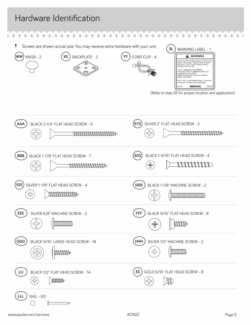
Step 3
å Fasten the FRONT LEGS (O and P) to the ENDS (A and B). Tighten six HIDDEN CAMS
412922 www.sauder.com/servicesPage 8
A
B
O
PAngled edge
Angled edge
1 2
Surface without
HIDDEN CAMS
Surface with HIDDEN CAMS

å Turn eight BLACK 9/16" FLAT HEAD SCREWS (FFF) into the ENDS (A and B) until the shoulders of the SCREWS rest on the surfaces of the ENDS.
å Slide the END MOLDINGS (M75) onto the ENDS (A and B). Line up the grooves in the MOLDINGS over the heads of the SCREWS in the ENDS and slide them until they are against the RIGHT FRONT LEGS (O and P).
å Fasten the RIGHT REAR LEGS (Q) to the ENDS (A and B). Use six BLACK 2 1/4" FLAT HEAD SCREWS (AAA).
Step 4
412922www.sauder.com/services Page 9
A
B
AAA
P
O
Q
Q
Angled edge
Angled edge
Shoulder
Apply pressure with your hands as you guide the MOLDINGS over the SCREWS and onto the END.
BLACK 9/16" FLAT HEAD SCREW(8 used in this step)
FFF
BLACK 2-1/4" FLAT HEAD SCREW(6 used in this step)
AAA
M75
M75
M75
M75
M75

Step 5
å Fasten the CABINET RIGHT (40CA) and CABINET LEFT (40CB) to the UPRIGHTS (C and D). Use four GOLD 5/16" FLAT HEAD SCREWS (3S) through holes #1 and #4.
412922 www.sauder.com/servicesPage 10
Surface with
HIDDEN CAM
43
2
1
C
D
Roller end
43
2
1
Surface with
HIDDEN CAMCurved edge
Curved edge
Roller end
GOLD 5/16" FLAT HEAD SCREW(4 used in this step)
3S

å Fasten the UPRIGHTS (C and D) to the SHELF (I). Tighten four HIDDEN CAMS.
Step 6
412922www.sauder.com/services Page 11
C
D
I
Start Tighten
Arrow
Minimum190 degrees
CautionRisk of damage or injury. HIDDEN CAMS must be completely tightened. HIDDEN CAMS that are not completely tightened may loosen, and parts may separate. To completely tighten:
Arrow
Maximum210 degrees
Curved edge
Finished edge
Surface with HIDDEN CAMS
Curved edge
Do not stand the unit upright without the BACK fastened. The unit may collapse.
Caution

Step 7
å Fasten the UPRIGHTS (C and D) to the BOTTOM (G2). Use four BLACK 1-7/8" FLAT HEAD SCREWS (BBB).
å Fasten the ENDS (A and B) to the BOTTOM (G2). Tighten four HIDDEN CAMS.
412922 www.sauder.com/servicesPage 12
A
B
C
D
G2
Arrow
Minimum190 degrees
Maximum210 degrees
BLACK 1-7/8" FLAT HEAD SCREW(4 used in this step)
BBB

å Fasten the SMALL BACK (J) to the SMALL BOTTOM (H). Use three BLACK 1-7/8" FLAT HEAD SCREWS (BBB).
å Push the GROMMETS (RR) and GROMMET CAPS (QQ) into the large holes in the SMALL BACK (J).
Step 8
412922www.sauder.com/services Page 13
Surface without
HIDDEN CAMSJ
H
RR
BLACK 1-7/8" FLAT HEAD SCREW(3 used in this step)
BBB
Edge with CAM DOWELS

Step 9
å Fasten the SMALL BACK (J) and SMALL BOTTOM (H) to the ENDS (A and B). Tighten four HIDDEN CAMS.
412922 www.sauder.com/servicesPage 14
A
B
H
Surface with
HIDDEN CAMS
J
Arrow
Minimum190 degrees
Maximum210 degrees

å Push four CORD CLIPS (YY) into the holes in the TOP (E).
å Fasten the TOP (E) to the ENDS (A and B) UPRIGHTS (C and D), and SMALL BACK (J). Tighten nine HIDDEN CAMS.
Step 10
412922www.sauder.com/services Page 15
YY
E
A
B
C
D
J
Arrow
Minimum190 degrees
Maximum210 degrees

Step 11
å Fasten fi ve ANGLE BRACKETS (GG) to the SKIRT (V). Use fi ve BLACK 9/16" LARGE HEAD SCREWS (GGG).
å NOTE: Be sure the edges of the ANGLE BRACKETS are even with the edges of the SKIRT.
å Now, fasten the SKIRT to the ENDS (A and B) and BOTTOM (G2). Use fi ve BLACK 9/16" LARGE HEAD SCREWS (GGG).
412922 www.sauder.com/servicesPage 16
V
GG
GG
GG
A
B
G2
BLACK 9/16" LARGE HEAD SCREW(10 used in this step)
GGG

å Turn your unit onto its top.
å Push a FOOT (JJ) over the bottom edge of each LEG (O, P and Q).
Step 12
412922www.sauder.com/services Page 17
JJ
JJ
P
Q
Q
O
Don't worry. It isn't Rome. This can be built in a day.

Step 13
å Carefully turn your unit over onto its front edges. Unfold the BACK (L) and lay it over your unit.
å Make equal margins along the short edges of the BACK (F). The BACK should be even with the TOP (E) and will overhang the BOTTOM (G) slightly. Push on opposite corners of your unit if needed to make it "square".
å Fasten the BACK (L) to your unit using the NAILS (LLL).
å NOTE: Be sure to tap NAILS into the holes that line up over the UPRIGHTS (C and D).
å NOTE: Perforations have been provided for access through the BACK. Carefully cut out the holes needed.
412922 www.sauder.com/servicesPage 18
These holes must line up over the UPRIGHTS (C and D).
L
E
These holes must be here.
Do not stand the unit upright without the BACK fastened. The unit may collapse.
Caution
Unfi nished surface
NAIL(60 used in this step)
LLL
Th BACK will overhang the BOTTOM slightly.
Th BACK should be even with the TOP.

Step 14
412922www.sauder.com/services Page 19
å Fasten the EXTENSION BLOCK (Y2) to the BOTTOM (G2). Use four SILVER 1-1/8" FLAT HEAD SCREWS (10S).
å Fasten two FOOT SPACERS (Z) to the EXTENSION BLOCK (Y2). Use two SILVER 2" FLAT HEAD SCREWS (57S).
å Push the FOOT (3E) into the center hole of the FOOT SPACER (Z).
Y2
ZZ
3E
G2
SILVER 1-1/8" FLAT HEAD SCREW(4 used in this step)
10S
SILVER 2" FLAT HEAD SCREW(2 used in this step)
57S

Step 15
412922 www.sauder.com/servicesPage 20
VV
VV
F
OO
Mounting screw(vertical)
Adjusting screw (depth)
(horizontal adjustment screws)
SW is stamped into this hinge for identifi cation.
å Fasten the SW HINGES (VV) to the FLIP TOP (F). Use six BLACK 1/2" FLAT HEAD SCREWS (JJJ).
å Push four BUMPERS (OO) into the FLIP TOP (F).
BLACK 1/2" FLAT HEAD SCREW(6 used in this step)
JJJ

Step 16
412922www.sauder.com/services Page 21
å Carefully stand your unit upright.
å Fasten the FLIP TOP (F) to the SMALL BACK (J). Use the screws in the HINGES.
å Refer to the enlarged diagram to identify the parts on the SW HINGES.
å The FLIP TOP may need some adjustments. Follow the text below to make needed adjustments.
å FLIP TOP ADJUSTMENTS:
å To adjust the FLIP TOP in or out (depth), turn the adjusting screw in or out.
å To adjust the FLIP TOP side to side (horizontal), loosen all horizontal adjustment screws. Move the FLIP TOP side to side so the edges are even with the TOP. Tighten the screws after making adjustments.
å To adjust the FLIP TOP up or down (vertical), loosen the mounting screw one turn and move the FLIP TOP up or down as needed. Tighten the mounting screw after making adjustments.
F
horizontal
verti
cal
depth
J
NOTE:
The FLIP-TOP will sit slightly higher
than the TOP.
Pro Tip: Lift with your legs. And, you know, your arms.
Mounting screw(vertical)
Adjusting screw (depth)(horizontal adjustment screws)
VV

Step 17
412922 www.sauder.com/servicesPage 22
å Fasten two METAL BRACKETS (HH) to the TOP MOLDING (X). Use two BLACK 9/16" LARGE HEAD SCREWS (GGG).
å NOTE: Be sure the edges of the METAL BRACKETS are even with the edges of the TOP MOLDING.
å Fasten the TOP MOLDING (X) to the ENDS (A and B) and SMALL BOTTOM (H). Tighten four HIDDEN CAMS.
å Fasten the METAL BRACKETS on the TOP MOLDING to the ENDS (A and B). Use two BLACK 9/16" LARGE HEAD SCREWS (GGG).
HH
HH
X
X
A
B H
All FLIP-TOP adjustments must be made before
fastening the TOP MOLDING (X).
Arrow
Minimum190 degrees
Maximum210 degrees
BLACK 9/16" LARGE HEAD SCREW(4 used for the METAL BRACKETS)
GGG
Rounded edge

Step 18
412922www.sauder.com/services Page 23
å Fasten the HINGES (UU) to the DOORS (K). Use eight BLACK 1/2" FLAT HEAD SCREWS (JJJ).
UU
UU
K
K
BLACK 1/2" FLAT HEAD SCREW(8 used in this step)
JJJ
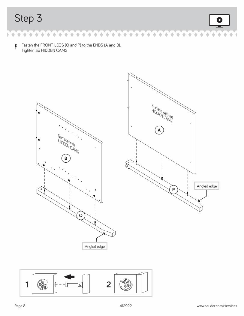
Step 19
412922 www.sauder.com/servicesPage 24
WWXX
KB
MM
D
å Fasten a DOOR (K) to the END (B). Use the screws in the HINGES.
å Fasten the BACKPLATE (XX) and KNOB (WW) to the DOOR. Use a BLACK 1-1/8" MACHINE SCREW (DDD).
å Peel the FELT DISCS from the FELT DISC CARDS (MM) and stick them on the corner of the DOOR (K) where they come in contact with the UPRIGHT (D).
å Repeat this step for the other DOOR.
BLACK 1-1/8" MACHINE SCREW(2 used for the BACKPLATE and KNOB)
DDD

Step 20
412922www.sauder.com/services Page 25
å Refer to the enlarged diagram to identify the parts on the HINGES.
å DOOR ADJUSTMENTS:
å To adjust the DOORS from side to side (horizontal), turn the adjusting screw in or out.
å To adjust the DOORS up and down (vertical), loosen both vertical adjustment screws. Move the DOORS up or down to the desired location. Tighten the screws after making adjustments.
å To adjust the DOORS in or out (depth), loosen the mounting screw one turn and move the DOORS in or out, as needed. Tighten the mounting screw after making adjustments.
Adjusting screw (horizontal)Mounting screw (depth)
(vertical adjustment)

Step 21
412922 www.sauder.com/servicesPage 26
å Fasten the DRAWER SIDES (D44 and D45) to the DRAWER BACK (D62). Use four BLACK 1-9/16" FLAT HEAD SCREWS (30S).
å Slide the DRAWER BOTTOM (D701) into the grooves in the DRAWER SIDES (D44 and D45) and DRAWER BACK (D62).
D45
D62
D44
D45D62
D44D701
Groove
Finished surface
BLACK 1-9/16" FLAT HEAD SCREW(4 used in this step)
30S

Step 22
412922www.sauder.com/services Page 27
å Pull the DRAWER FRONT BRACKETS (II) apart and slide them into the grooves in the DRAWER SIDES (D44 and D45).
å Fasten the DRAWER FRONT (R) to the DRAWER FRONT BRACKETS. Use four BLACK 9/16" LARGE HEAD SCREWS (GGG).
Push down
Separate the DRAWER FRONT BRACKETS (II) and slide them into the grooves in the DRAWER SIDES.
II
II
R
D44
D45
D44
BLACK 9/16" LARGE HEAD SCREW(4 used in this step)
GGG
Groove

Step 23
412922 www.sauder.com/servicesPage 28
å Fasten the DRAWER RIGHT (40CC) and DRAWER LEFT (40CD) to the DRAWER SIDES (D44 and D45). Use four GOLD 5/16" FLAT HEAD SCREWS (3S) through holes #2 and #4.
å Fasten a PULL (PP) to the DRAWER FRONT (R). Use two SILVER 1/2" MACHINE SCREWS (HHH).
PP
RD44
D45
Roller end
Roller end
43
21
4 3
21
GOLD 5/16" FLAT HEAD SCREW(4 used for the SLIDES)
3S
SILVER 1/2" MACHINE SCREW(2 used for the PULL)
HHH

Step 24
412922www.sauder.com/services Page 29
å Push the RUBBER SLEEVES (SS) over the METAL PINS (TT). Insert the METAL PINS into the hole locations of your choice in the ENDS (A and B) and UPRIGHTS (C and D). Set the ADJUSTABLE SHELVES (M and N) onto the METAL PINS.
å To insert the drawer into your unit, tip the front of the drawer down and drop the rollers on the drawer behind the rollers on the unit. Lift the front of the drawer up and slide it into the unit.
å To make adjustments to the drawer, loosen the SCREWS in the DRAWER FRONT BRACKETS, make needed adjustments, and tighten the SCREWS.
SS
TTA
B
C
D
M
M
M
M
N
E
Place the roller on the SLIDE behind the roller on the RAIL.
(20 used)
Step 25
412922 www.sauder.com/servicesPage 30
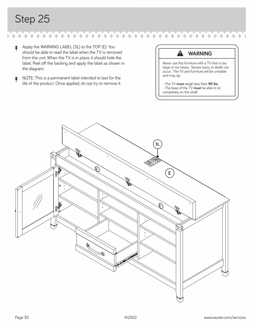
å Apply the WARNING LABEL (3L) to the TOP (E). You should be able to read the label when the TV is removed from the unit. When the TV is in place, it should hide the label. Peel off the backing and apply the label as shown in the diagram.
å NOTE: This is a permanent label intended to last for the life of the product. Once applied, do not try to remove it.
E
3L
WARNINGNever use this furniture with a TV that is too large or too heavy. Severe injury or death can occur. The TV and furniture will be unstable and may tip.
- The TV must weigh less than 95 lbs.- The base of the TV must be able to sit completely on this shelf.

Step 26
412922www.sauder.com/services Page 31
å NOTE: Please read the back pages of the instruction booklet for important safety information.
å This completes assembly. Clean with your favorite furniture polish or a damp cloth. Wipe dry.
20 lbs.
30 lbs.
30 lbs.
25 lbs.
25 lbs.
25 lbs.
25 lbs.
50 lbs. total
15 lbs.
95 lbs.

A l’usage exclusif du Canada Noter la date d’achat de cet élément et conserver le livret pour future référence. Pour contacter Sauder en ce qui concerne cet élément, faire référence au numéro de lot et numéro de modèle en appelant notre numéro sans frais.
Lot nº : ____________
Date del’achat: ____________
LISTE DE PIÈCESREFERENCE DESCRIPTION QUANTITÉ
LISTE DE PIÈCESREFERENCE DESCRIPTION QUANTITÉ
NOUS SOMMES LA POUR VOUS AIDER!Nous faisons de notre mieux pour nous assurer que votre meuble arrive dans d’excellentes conditions. Nos représentants du service Clientèle sont aimables et prêts à vous aider au cas où une pièce aurait été endommagée ou manquerait (ou si vous aviez besoin d’aide pour l’assemblage). NE RAMENEZ PAS LE MEUBLE AU MAGASIN. Au Canada, composez ce numéro d’appel gratuit:
1-800-523-3987Du lundi au vendredi, de 9 heures du matin à
5:30 heures du soir (horaire Côte Est)(sauf jours fériés)
Si une pièce a besoin d’être remplacée, la pièce de remplacement sera envoyée dans les 48 heures. (Sauf week-ends et jours fériés)
Utilisez les instructions d’assemblage en français avec les schémas étape par étape du manuel d’instruction en anglais. Chaque étape en français correspond à la même étape en anglais. La pièce devant être attachée à l’élément est représentée en gris sur les schémas de chaque étape pour plus de précision. Comparer la “Liste de pièces” ci-dessous avec la “PART IDENTIFICATION” du manuel en anglais pour vous familiariser avec les pièces avant l’assemblage.
REMARQUE : CE MANUEL D’INSTRUCTIONS CONTIENT D’IMPORTANTES INFORMATIONS RELATIVES À LA SÉCURITÉ. À LIRE ET CONSERVER POUR TOUTE RÉFÉRENCE FUTURE.
Crédence télévision/vidéo/stéréoModèle 412922
HH CONSOLE EN MÉTAL .............................................2II CONSOLE DE DEVANT DE TIROIR ...............1JJ PIED ........................................................................................4MM FICHE DE TAMPONS EN FEUTRE..................1NN ACCENT D’ANGLE .....................................................2OO TAMPON ............................................................................4PP POIGNÉE .............................................................................1QQ COUVERCLE DE PASSE-CÂBLES ................2RR PASSE-CÂBLES ...........................................................2SS MANCHON EN CAOUTCHOUC .................20TT GOUPILLE EN MÉTAL .........................................20UU CHARNIÈRE .....................................................................4VV CHARNIÈRE SW ...........................................................3WW BOUTON ............................................................................2XX FERRURE ............................................................................2YY CLIP DE CORDON ......................................................4
AAA VIS NOIRE TÊTE PLATE 57 mm .....................6BBB VIS NOIRE TÊTE PLATE 48 mm ..................... 7DDD VIS NOIRE À MÉTAUX 28 mm .........................2EEE VIS ARGENTÉE À MÉTAUX 16 mm ..............2FFF VIS NOIRE TÊTE PLATE 14 mm ......................8GGG VIS NOIRE TÊTE LARGE 14 mm .................. 18HHH VIS ARGENTÉE À MÉTAUX 13 mm ..............2JJJ VIS NOIRE TÊTE PLATE 13 mm ....................14LLL CLOU ................................................................................603S VIS DORÉE TÊTE PLATE 8 mm ......................830S VIS TÊTE PLATE 40 mm NOIRE ....................410S VIS TÊTE PLATE 28 mm ARGENTÉE .........457S VIS TÊTE PLATE 51 mm ARGENTÉE ..........23E PIED .........................................................................................13L ÉTIQUETTE D’AVERTISSEMENT .....................1(Consulter l’étape 25 pour l'emplacement et application appropriées)
A EXTRÉMITÉ DROITE ..................................................1B EXTRÉMITÉ GAUCHE ...............................................1C MONTANT DROIT ........................................................1D MONTANT GAUCHE .................................................1E DESSUS ...............................................................................1F DESSUS RELEVABLE ................................................1G2 DESSOUS ...........................................................................1H PETIT DESSOUS ..........................................................1I TABLETTE ..........................................................................1J PETIT ARRIÈRE ..............................................................1K PORTE ..................................................................................2L ARRIÈRE ..............................................................................1M TABLETTE RÉGLABLE ............................................4N PETITE TABLETTE RÉGLABLE ..........................1O PIED AVANT GAUCHE .............................................1P PIED AVANT DROIT ....................................................1Q PIED ARRIÈRE ................................................................2R DEVANT DE TIROIR ....................................................1V PLINTHE ..............................................................................1X MOULURE DE DESSUS ..........................................1Y BLOC D'EXTENSION .................................................1D44 CÔTÉ DROIT DE TIROIR ........................................1D45 CÔTÉ GAUCHE DE TIROIR ..................................1D62 ARRIÈRE DE TIROIR ...................................................1D701 FOND DE TIROIR ..........................................................1M75 MOULURE D’EXTRÉMITÉ .....................................4
40CA ÉLÉMENT DROITE.......................................................140CB ÉLÉMENT GAUCHE ...................................................140CC TIROIR DROITE ..............................................................140CD TIROIR GAUCHE ...........................................................11F EXCENTRIQUE ESCAMOTABLE ...................312F CHEVILLE D'EXCENTRIQUE .......................... 258F VIS D'EXCENTRIQUE ...............................................6GG CONSOLE À ÉQUERRE .........................................5
412922 www.sauder.com/servicesPage 32

AVERTISSEMENTL'utilisation d'un téléviseur trop lourd ou trop gros est dangereuse. Un téléviseur trop lourd créera un risque de basculement pouvant provoquer de graves blessures ou la mort. Un téléviseur trop gros pour l'espace disponible risque d'être accidentellement poussé ou de tomber du mobilier ou d'être sujet à basculer.
• Vérifi er la taille et le poids du téléviseur. Le comparer au diagramme ci-dessous avant de commencer l'assemblage !
• Cette unité Sauder est conçue pour les téléviseurs pesant moins de 43 kg. Ne jamais utiliser avec des téléviseurs plus lourds.
• La taille du téléviseur, d'avant en arrière et latéralement, doit rentrer dans l'espace défi ni sur le schéma.
• Ne jamais placer le devant du téléviseur au-delà du devant de la tablette de support de téléviseur (ou de la moulure de butée, le cas échéant).
• Ne jamais laisser les côtés du téléviseur dépasser les bords latéraux de la surface de support du téléviseur.
• Si le téléviseur comporte un tube cathodique à image, le cône du tube image peut dépasser l'arrière de la tablette de support.
• S'assurer d'apposer l'étiquette d'avertissement comme indiqué à la dernière étape d'assemblage. L'étiquette fournit d'importants renseignements relatifs à la sécurité.
ÉTAPE 2Faire tourner six VIS D'EXCENTRIQUE (8F) dans les PIEDS AVANT (O et P).
Fixer un ACCENT D’ANGLE (NN) à chaque PIED AVANT (O et P). Utiliser deux VIS ARGENTÉES À MÉTAUX 16 mm (EEE).
ÉTAPE 1Ne pas serrer les EXCENTRIQUES ESCAMOTABLES dans cette étape.
Assembler l'élément sur un sol à moquette ou sur le carton vide pour éviter d'endommager l'élément ou le sol.
Enfoncer trente et un EXCENTRIQUES ESCAMOTABLES (1F) dans les EXTRÉMITÉS (A et B), les MONTANTS (C et D), le DESSOUS (G2), le PETIT DESSOUS (H), la TABLETTE (I) et le PETIT ARRIÈRE (J). Insérer la fi n de métal ensuite une CHEVILLE D’EXCENTRIQUE (2F) dans chaque EXCENTRIQUE ESCAMOTABLE, à l'exception des chants longs des EXTRÉMITÉS (A et B).
ÉTAPE 4Faire tourner huit VIS NOIRES TÊTE PLATE 14 mm (FFF) dans les EXTRÉMITÉS (A et B) jusqu'à ce que l'épaulement des VIS repose sur la surface des EXTRÉMITÉS.
Enfi ler les MOULURES D'EXTRÉMITÉ (M75) sur les EXTRÉMITÉS (A et B). Aligner la rainure dans la MOULURE sur la tête des VIS dans l’EXTRÉMITÉ et la faire glisser jusqu’à ce que celle-ci se trouve contre les PIEDS AVANT DROITS (O et P).
Fixer les PIEDS ARRIÈRE DROITS (Q) aux EXTRÉMITÉS (A et B). Utiliser six VIS NOIRES TÊTE PLATE 57 mm (AAA).
ÉTAPE 7Fixer les MONTANTS (C et D) au DESSOUS (G2). Utiliser quatre VIS NOIRES TÊTE PLATE 48 mm (BBB).
Fixer les EXTRÉMITÉS (A et B) au DESSOUS (G2). Serrer quatre EXCENTRIQUES ESCAMOTABLES.
ÉTAPE 6Attention: Ne pas relever l'élément dans sa position verticale avant d'avoir fi xé l’ARRIÈRE. L'élément risque de s'eff ondrer.
Fixer les MONTANTS (C et D) sur la TABLETTE (I). Serrer quatre EXCENTRIQUES ESCAMOTABLES.
Attention: Risque des dégâts ou blessures. Les Excentriques Escamotables doivent être serrés à bloc. Les Excentriques Escamotables que ne sont pas serrées à bloc peuvent desserrer et les pièces peuvent séparer. Pour serrer à bloc, faire tourner l'excentrique escamotable de 210 degrés.
ÉTAPE 5Fixer lÉLÉMENT DROITE (40CA) et lÉLÉMENT GAUCHE (40CB) aux MONTANTS (C et D). Utiliser quatre VIS DORÉES TÊTE PLATE 8 mm (3S) à travers les trous nº 1 et nº 4.
ÉTAPE 3Fixer les PIEDS AVANT (O et P) aux EXTRÉMITÉS (A et B). Serrer six EXCENTRIQUES ESCAMOTABLES.
ÉTAPE 8Fixer le PETIT ARRIÈRE (J) au PETIT DESSOUS (H). Utiliser trois VIS NOIRES TÊTE PLATE 48 mm (BBB).
Enfoncer les PASSE-CÂBLES (RR) et les CAPUCHONS DE PASSE-CÂBLES (QQ) dans les gros trous du PETIT ARRIÈRE (J).
ÉTAPE 9Fixer le PETIT ARRIÈRE (J) et PETIT DESSOUS (H) aux EXTRÉMITÉS (A et B). Serrer quatre EXCENTRIQUES ESCAMOTABLES.
412922www.sauder.com/services Page 33

ÉTAPE 10Faire tourner quatre CLIPS DE CORDON (YY) dans les trous du DESSUS (E).
Fixer le DESSUS (E) aux EXTRÉMITÉS (A et B), aux MONTANTS (C et D) et PETIT ARRIÈRE (J). Serrer neuf EXCENTRIQUES ESCAMOTABLES.
ÉTAPE 12Avec précaution, retourner l'élément sur son dessus.
Mettre un PIED (JJ) sur le chant inférieur de chaque PIED (O, P et Q).
ÉTAPE 11Fixer cinq CONSOLES À ÉQUERRE (GG) à la PLINTHE (V). Utiliser cinq VIS NOIRES TÊTE LARGE 14 mm (GGG).
REMARQUE : S'assurer que les chants des CONSOLES À ÉQUERRE sont à fl eur des chants de la PLINTHE.
Maintenant, fi xer la PLINTHE aux EXTRÉMITÉS (A et B) et au DESSOUS (G2). Utiliser cinq VIS NOIRES TÊTE LARGE 14 mm (GGG).
ÉTAPE 14Fixer le BLOC D’EXTENSION (Y2) au DESSOUS (G2). Utiliser quatre VIS TÊTE PLATE 28 mm ARGENTÉES (10S).
Fixer les deux ESPACEURS DE PIED (Z) au BLOC D'EXTENSION (Y2). Utiliser deux VIS TÊTE PLATE 51 mm ARGENTÉES (57S).
Enfoncer le PIED (3E) dans le trou central de l'ESPACEUR DE PIED (Z).
ÉTAPE 13Attention: Ne pas relever l'élément dans sa position verticale avant d'avoir fi xé l’ARRIÈRE. L'élément risque de s'eff ondrer.
Avec précaution, retourner l'élément sur ses chants avant. Déplier l'ARRIÈRE (L) et le placer sur l'élément.
Veiller à avoir des marges égales le long des chants longs de l'ARRIÈRE (L). Si besoin est, enfoncer sur les coins opposés de l'élément pour s'assurer d'être « d'équerre ».
Fixer l'ARRIÈRE (L) à l'élément à l'aide des CLOUS (LLL).
REMARQUE : S'assurer de bien enfoncer les CLOUS dans les trous qui sont alignés sur les MONTANTS (C et D).
REMARQUE : Des lignes perforées ont été prévues pour accéder facilement à l'ARRIÈRE. Découper avec précaution les trous nécessaires.
ÉTAPE 16Relever, avec précaution, l'élément dans sa position verticale.
Fixer le DESSUS RELEVABLE (F) sur le PETIT ARRIÈRE (J). Utiliser les vis fournies avec les CHARNIÈRES.
Consulter le schéma agrandi pour identifi er les pièces sur les CHARNIÈRES SW.
Il faudra peut-être ajuster le DESSUS RELEVABLE. Suivre les indications ci-dessous pour ajuster.
RÉGLAGES DU DESSUS RELEVABLE :
Pour ajuster le DESSUS RELEVABLE d'avant en arrière (en profondeur), visser ou dévisser la vis de réglage, selon les besoins.
Pour ajuster le DESSUS RELEVABLE latéralement (horizontalement), desserrer toutes les vis de réglage horizontal. Déplacer le DESSUS RELEVABLE latéralement de manière à ce que les chants soient à fl eur du DESSUS. Serrer les vis après avoir ajusté.
Pour régler le DESSUS RELEVABLE vers le haut ou vers le bas (verticalement), desserrer la vis de montage d’un tour et déplacer le DESSUS RELEVABLE vers le haut ou le bas selon les besoins. Serrer la vis de montage après avoir ajusté.
ÉTAPE 15Fixer les CHARNIÈRES SW (VV) sur le DESSUS RELEVABLE (F). Utiliser six VIS NOIRES TÊTE PLATE 13 mm (JJJ).
Enfoncer quatre TAMPONS (OO) dans le DESSUS RELEVABLE (F).
412922 www.sauder.com/servicesPage 34

ÉTAPE 17Fixer deux CONSOLES EN MÉTAL (HH) sur les MOULURES DE DESSUS (X). Utiliser deux VIS NOIRES TÊTE LARGE 14 mm (GGG).REMARQUE : S'assurer que les chants des CONSOLES EN MÉTAL sont à fl eur des chants de la MOULURE DE DESSUS.Fixer la MOULURE DE DESSUS (X) aux EXTRÉMITÉS (A et B) et au PETIT DESSOUS (H). Serrer quatre EXCENTRIQUES ESCAMOTABLES.Fixer les CONSOLES EN MÉTAL situées sur la MOULURE DE DESSUS aux EXTRÉMITÉS (A et B). Utiliser deux VIS NOIRES TÊTE LARGE 14 mm (GGG).
ÉTAPE 22Séparer les CONSOLES DE DEVANT DE TIROIR (II) et les enfi ler dans les rainures des CÔTÉS DE TIROIR (D44 et D45).
Fixer le DEVANT DE TIROIR (R) aux CONSOLES DE DEVANT DE TIROIR. Utiliser quatre VIS NOIRES TÊTE LARGE 14 mm (GGG).
ÉTAPE 24Enfoncer les MANCHONS EN CAOUTCHOUC (SS) sur les GOUPILLES EN MÉTAL (TT). Insérer les GOUPILLES EN MÉTAL dans les trous choisis dans les EXTRÉMITÉS (A et B) et MONTANTS (C et D). Poser les TABLETTES RÉGLABLES (M et N) sur les GOUPILLES EN MÉTAL.
Pour insérer le tiroir dans l'élément, abaisser le devant du tiroir et faire passer les roulettes situées sur le tiroir derrière les roulettes situées sur l'élément. Relever le devant du tiroir et l'enfi ler dans l'élément.
Pour ajuster le tiroir, desserrer les VIS dans les CONSOLES DE DEVANT DE TIROIR, ajuster et serrer les VIS.
ÉTAPE 23Fixer le TIROIR DROITE (40CC) et le TIROIR GAUCHE (40CD) aux CÔTÉS DE TIROIR (D44 et D45). Utiliser quatre VIS DORÉES TÊTE PLATE 8 mm (3S) à travers les trous nº 2 et nº 4.
Fixer une POIGNÉE (PP) au DEVANT DE TIROIR (R). Utiliser deux VIS ARGENTÉES À MÉTAUX 13 mm (HHH).
ÉTAPE 20Consulter le schéma agrandi pour identifi er les pièces des CHARNIÈRES.RÉGLAGES DES PORTES :Pour ajuster les PORTES latéralement (horizontalement), tourner la vis de réglage vers l'intérieur ou vers l'extérieur.Pour ajuster les PORTES de haut en bas (verticalement), desserrer les deux vis de réglage. Déplacer les PORTES verticalement à l'emplacement désiré. Serrer les vis après avoir ajusté.Pour ajuster les PORTES vers l'intérieur où vers l'extérieur (profondeur), desserrer la vis de montage un tour et déplacer les PORTES vers l'intérieur ou vers l'extérieur. Serrer la vis de montage après avoir ajusté.
ÉTAPE 19Fixer une PORTE (K) à l'EXTRÉMITÉ (B). Utiliser les vis fournies avec les CHARNIÈRES.Fixer une FERRURE (XX) et un BOUTON (WW) à la PORTE. Utiliser une VIS NOIRE À MÉTAUX 28 mm (DDD).Décoller les TAMPONS EN FEUTRE des FICHES DE TAMPONS EN FEUTRE (MM) et les coller sur le coin de la PORTE (K) où ils entrent en contact avec le MONTANT (D).Répéter cette étape pour l'autre PORTE.
ÉTAPE 18Fixer les CHARNIÈRES (UU) aux PORTES (K). Utiliser huit VIS NOIRES TÊTE PLATE 13 mm (JJJ).
ÉTAPE 25Apposer l'ÉTIQUETTE DE MISE EN GARDE (3L) au DESSUS (E). Cette étiquette doit pouvoir être lisible lorsque le téléviseur est enlevé de l'élément. Lorsque le téléviseur est en place, il doit la dissimuler. Décoller le fi lm protecteur et apposer l'étiquette comme l'indique le schéma.
REMARQUE : Cette étiquette permanente est prévue pour durer pendant toute la vie du produit. Une fois apposée ne pas essayer de la retirer.
ÉTAPE 21Fixer CÔTÉS DE TIROIR (D44 et D45) aux l'ARRIÈRE DE TIROIR (D62). Utiliser quatre VIS TÊTE PLATE 40 mm NOIRES (30S).Enfi ler le FOND DE TIROIR (D701) dans les rainures des CÔTÉS DE TIROIR (D44 et D45) et de l'ARRIÈRE DE TIROIR (D62).
ÉTAPE 26REMARQUE : Prière de lire attentivement les importantes informations concernant la sécurité qui fi gurent sur la couverture arrière du manuel d'instructions.
Ceci complète l'assemblage. Pour nettoyer, utiliser l'encaustique pour meubles préférée ou un chiff on humide. Essuyer.
412922www.sauder.com/services Page 35

A l’usage exclusif du Canada Noter la date d’achat de cet élément et conserver le livret pour future référence. Pour contacter Sauder en ce qui concerne cet élément, faire référence au numéro de lot et numéro de modèle en appelant notre numéro sans frais.
Lot nº : ____________
Date del’achat: ____________
LISTA DE PARTESITEM DESCRIPCIÓN CANTIDAD
ESTAMOS AQUI PARA AYUDAR!Tratamos de asegurar que su mueble llega en condición excelente. Nuestros representantes de Servicio al Cliente son amables y listos para ayudarle con servicio rápido y efi ciente si una parte está defectuosa o ausente (o si necesita ayuda con el ensamblaje). NO DEVUELVA LA UNIDAD A LA TIENDA. Llame este número sin cargo:
1-800-523-3987Lunes a viernes, 9:00 a.m. - 5:30 p.m.
Hora ofi cial del Este(excepto días festivos)
Si requiere un repuesto de una parte, será enviado dentro de 48 horas (excepto los fi nes de semana y días festivos)
Use estas instrucciones de ensamblaje en español junto con las fi guras paso-a-paso provistas en el folleto inglés. Cada paso en español corresponde al mismo paso en inglés. Se destacan las fi guras de cada paso con una tonalidad oscura para mostrar precisamente cual parte se debe montar a la unidad. Compare la “Lista de Part” abajo con la “Part Identifi cation” en el folleto en inglés para familiarizarse con Las partes de ensamblaje.
NOTA: ESTE FOLLETO DE INSTRUCCIONES CONTIENE INFORMACIÓN IMPORTANTE SOBRE LA SEGURIDAD. POR FAVOR LEA Y GUÁRDELO PARA REFERENCIA EN EL FUTURO.
MM TARJETA CON TOPES DE FIELTRO ......................... 1NN ACENTO DE ESQUINA ...................................................... 2OO TOPE ................................................................................................4PP TIRADOR ........................................................................................ 1QQ CUBIERTA DE OJAL ............................................................. 2RR OJAL ............................................................................................... 2SS MANGUITO DE GOMA .................................................. 20TT ESPIGA DE METAL ........................................................... 20UU BISAGRA .......................................................................................4VV BISAGRA SW .............................................................................3WW TIRADOR ....................................................................................... 2XX PLACA DE TIRADOR ........................................................... 2YY GRAPA DE CABLE .................................................................4AAA TORNILLO NEGRO DE CABEZA PERDIDA de 57 mm .............................................................6BBB TORNILLO NEGRO DE CABEZA PERDIDA de 48 mm .............................................................7DDD TORNILLO NEGRO PARA METAL de 28 mm ........ 2EEE TORNILLO PLATEADO PARA METAL de 16 mm ...................................................................................... 2FFF TORNILLO NEGRO DE CABEZA PERDIDA de 14 mm .............................................................8GGG TORNILLO NEGRO DE CABEZA GRANDE de 14 mm ............................................................18HHH TORNILLO PLATEADO PARA METAL de 13 mm ................................................................... 2JJJ TORNILLO NEGRO DE CABEZA PERDIDA de 13 mm ...........................................................14LLL CLAVO ....................................................................................... 603S TORNILLO DORADO DE CABEZA PERDIDA de 8 mm ................................................................830S TORNILLO NEGRO DE CABEZA PERDIDA de 40 mm ............................................................410S TORNILLO PLATEADO DE CABEZA PERDIDA de 28 mm ............................................................457S TORNILLO PLATEADO DE CABEZA PERDIDA de 51 mm ............................................................. 23E PATA ................................................................................................... 13L ETIQUETA DE ADVERTENCIA ...................................... 1(Consulte el paso 25 para la ubicación e instalación apropiada)
A EXTREMO DERECHO ....................................................................... 1B EXTREMO IZQUIERDO .................................................................... 1C PARAL DERECHO................................................................................ 1D PARAL IZQUIERDO ............................................................................ 1E PANEL SUPERIOR ............................................................................... 1F PANEL SUPERIOR ABATIBLE..................................................... 1G2 FONDO ........................................................................................................ 1H FONDO PEQUEÑO ............................................................................ 1I ESTANTE ..................................................................................................... 1J DORSO PEQUEÑO ............................................................................. 1K PUERTA ....................................................................................................... 2L DORSO ......................................................................................................... 1M ESTANTE AJUSTABLE ....................................................................4N ESTANTE AJUSTABLE PEQUEÑO ......................................... 1O PATA DELANTERA IZQUIERDA ................................................ 1P PATA DELANTERA DERECHA ................................................... 1Q PATA POSTERIOR............................................................................... 2R CARA DE CAJÓN................................................................................. 1V FALDÓN....................................................................................................... 1X MOLDURA DE PANEL SUPERIOR .......................................... 1Y BLOQUE DE EXTENSIÓN .............................................................. 1D44 LADO DERECHO DE CAJÓN ..................................................... 1D45 LADO IZQUIERDO DE CAJÓN .................................................. 1D62 DORSO DE CAJÓN ............................................................................ 1D701 FONDO DE CAJÓN ............................................................................ 1M75 MOLDURA DE EXTREMO ............................................................4
40CA GABINETE DERECHO ...................................................................... 140CB GABINETE IZQUIERDO ................................................................... 140CC CAJÓN DERECHO .............................................................................. 140CD CAJÓN IZQUIERDO ........................................................................... 11F EXCÉNTRICO ESCONDIDO .....................................................312F PASADOR DE EXCÉNTRICO ..................................................258F BIELA DE EXCÉNTRICO ................................................................6GG SOPORTE ANGULAR ......................................................................5HH SOPORTE DE METAL ...................................................................... 2II MÉNSULA DE CARA DE CAJÓN ............................................ 1JJ PATA ..................................................................................................4
LISTA DE PARTESITEM DESCRIPCIÓN CANTIDAD
Credencia de EntretenimientoModelo 412922
412922 www.sauder.com/servicesPage 36

ADVERTENCIAEl uso de un televisor demasiado pesado o grande es peligroso. Un televisor demasiado pesado generará riesgo de caída, lo cual podría causar lesiones graves o muerte. Un televisor demasiado grande para el espacio disponible puede ser empujado o golpeado por accidente, causando que éste se salga del mueble o se caiga.• Verifi que el tamaño y peso del televisor. ¡Compárelo al diagrama abajo - antes de comenzar el ensamblaje!• Esta unidad Sauder está diseñada para ser usada con televisores cuyo peso sea inferior a 43 Kg. Nunca la use para un televisor de mayor peso.• El tamaño del televisor, del frente al extremo posterior, y de un lado al otro, debe caber dentro del espacio defi nido en el diagrama.• Nunca coloque el borde frontal del televisor más adelante del borde frontal del estante de soporte del televisor (o de la moldura de tope, si existe tal equipamiento)• Nunca permita que los lados del televisor se extiendan más allá de los bordes laterales de la superfi cie de soporte del televisor.• Si el televisor tiene un tubo CRT, el cono del mismo puede extenderse más allá de la parte trasera del estante de soporte.• Asegúrese de colocar la etiqueta de advertencia según las instrucciones, en el último paso del armado. La etiqueta ofrece información importante de seguridad.
PASO 2Apriete seis BIELAS DE EXCÉNTRICO (8F) dentro de las PATAS DELANTERAS (O y P).Fije un ACENTO DE ESQUINA (NN) a cada PATA DELANTERA (O y P). Utilice dos TORNILLOS PLATEADOS PARA METAL de 16 mm (EEE).
PASO 1No apriete los EXCÉNTRICOS ESCONDIDOS en este paso.Ensamble la unidad sobre un piso alfombrado o sobre el cartón vacío para evitar rayar la unidad o el piso.Empuje treinta y uno EXCÉNTRICOS ESCONDIDOS (1F) dentro de los EXTREMOS (A y B), los PARALES (C y D), del FONDO (G2), del FONDO PEQUEÑO (H), del ESTANTE (I) y del DORSO PEQUEÑO (J). A continuación, inserte el éxtremo de métal de un PASADOR DE EXCÉNTRICO (2F) dentro de cada EXCÉNTRICO ESCONDIDO, menos en los bordes largos de los EXTREMOS (A y B).
PASO 4Atornille ocho TORNILLOS NEGROS DE CABEZA PERDIDA de 14 mm (FFF) dentro de los EXTREMOS (A y B) hasta que el resalto de los TORNILLOS repose sobre la superfi cie de los EXTREMOS.
Deslice las MOLDURAS DE EXTREMO (M75) sobre los EXTREMOS (A y B). Alinee la ranura en la MOLDURA sobre la cabeza de los TORNILLOS en el EXTREMO y deslícelo hasta que esté contra las PATAS DELANTERAS DE LA DERECHA (O y P).
Fije las PATAS POSTERIORES DE LA DERECHA (Q) a los EXTREMOS (A y B). Utilice seis TORNILLOS NEGROS DE CABEZA PERDIDA de 57 mm (AAA).
PASO 7Fije los PARALES (C y D) al FONDO (G2). Utilice cuatro TORNILLOS NEGROS DE CABEZA PERDIDA de 48 mm (BBB).
Fije los EXTREMOS (A y B) al FONDO (G2). Apriete cuatro EXCÉNTRICOS ESCONDIDOS.
PASO 6Precaución: No coloque la unidad en posición vertical hasta que se fi je el DORSO. La unidad podría caerse.
Fije los PARALES (C y D) al ESTANTE (I). Apriete cuatro EXCÉNTRICOS ESCONDIDOS.
Precaución: Riesgo de daños o heridas. Los Excéntricos Escondidos deben apretarse completamente. Los Excéntricos Escondidos que no se aprieten completamente se afl ojarán y las partes pueden separarse. Para apretar completamente, atornille el excéntrico escondido 210 grados.
PASO 5Fije el GABINETE DERECHO (40CA) y el GABINETE IZQUIERDO (40CB) a los PARALES (C y D). Utilice cuatro tornillos DORADOS de cabeza PERDIDA de 8 mm (3S) a través de los agujeros No. 1 y No. 4.
PASO 3Fije las PATAS DELANTERAS (O y P) a los EXTREMOS (A y B). Apriete seis EXCÉNTRICOS ESCONDIDOS.
PASO 8Fije el DORSO PEQUEÑO (J) al FONDO PEQUEÑO (H). Utilice tres TORNILLOS NEGROS DE CABEZA PERDIDA de 48 mm (BBB).
Inserte los OJALES (RR) y las CUBIERTAS DE OJAL (QQ) dentro de los agujeros grandes del DORSO PEQUEÑO (J).
PASO 9Fije el DORSO PEQUEÑO (J) y el FONDO PEQUEÑO (H) a los EXTREMOS (A y B). Apriete cuatro EXCÉNTRICOS ESCONDIDOS.
412922www.sauder.com/services Page 37

PASO 10Introduzca girando cuatro GRAPAS DE CABLE (YY) dentro los agujeros en el PANEL SUPERIOR (E).
Fije el PANEL SUPERIOR (E) a los EXTREMOS (A y B), los PARALES (C y D) y al DORSO PEQUEÑO (J). Apriete nueve EXCÉNTRICOS ESCONDIDOS.
PASO 13Precaución: No coloque la unidad en posición vertical hasta que se fi je el DORSO. La unidad podría caerse.Cuidadosamente voltee la unidad para que repose sobre los bordes delanteros. Desdoble el DORSO (L) y colóquelo sobre la unidad.Verifi que que los márgenes son iguales a lo largo de los bordes largos del DORSO (L). Empuje sobre las esquinas opuestas de la unidad si es requerido para hacerla "cuadrada."Fije el DORSO (L) a la unidad usando los CLAVOS (LLL).NOTA: Asegúrese de clavar ligeramente los CLAVOS dentro de los agujeros que se alinean sobre los PARALES.NOTA: Hay perforaciones provistas para el acceso a través del DORSO. Cuidadosamente corte los agujeros necesarios.
PASO 12Cuidadosamente voltee la unidad para que repose sobre el panel superior.
Introduzca una PATA (JJ) sobre el borde inferior de cada PATA (O, P y Q).
PASO 11Fije cinco SOPORTES ANGULARES (GG) al FALDÓN (V). Utilice cinco TORNILLOS NEGROS DE CABEZA GRANDE de 14 mm (GGG).
NOTA: Asegúrese que los bordes de los SOPORTES ANGULARES estén nivelados con los bordes del FALDÓN.
Ahora, fi je el FALDÓN a los EXTREMOS (A y B) y al FONDO (G2). Utilice cinco TORNILLOS NEGROS DE CABEZA GRANDE de 14 mm (GGG).
PASO 15Fije las BISAGRAS SW (VV) al PANEL SUPERIOR ABATIBLE (F). Utilice seis TORNILLOS NEGROS DE CABEZA PERDIDA de 13 mm (JJJ).
Presione cuatro TOPES (OO) en el PANEL SUPERIOR ABATIBLE (F).
PASO 14Fije el BLOQUE DE EXTENSIÓN (Y2) al FONDO (G2). Utilice cuatro TORNILLOS PLATEADOS DE CABEZA PERDIDA de 28 mm (10S).Fije dos ESPACIADORES DE PATA (Z) al BLOQUE DE EXTENSIÓN (Y2). Utilice dos TORNILLOS PLATEADOS DE CABEZA PERDIDA de 51 mm (57S).Introduzca la PATA (3E) dentro del agujero central en el ESPACIADOR DE PATA (Z).
PASO 17Fije dos SOPORTES DE METAL (HH) a la MOLDURA DE PANEL SUPERIOR (X). Utilice dos TORNILLOS NEGROS DE CABEZA GRANDE de 14 mm (GGG).
NOTA: Asegúrese que los bordes de los SOPORTES DE METAL estén a nivel con los bordes de la MOLDURA DEL PANEL SUPERIOR.
Fije la MOLDURA DE PANEL SUPERIOR (X) a los EXTREMOS (A y B) y al FONDO PEQUEÑO (H). Apriete cuatro EXCÉNTRICOS ESCONDIDOS.
Fije los SOPORTES DE METAL sujetados a la MOLDURA DE PANEL SUPERIOR a los EXTREMOS (A y B). Utilice dos TORNILLOS NEGROS DE CABEZA GRANDE de 14 mm (GGG).
PASO 16Cuidadosamente ponga la unidad en posición vertical.
Fije el PANEL SUPERIOR ABATIBLE (F) al DORSO PEQUEÑO (J). Utilice los tornillos provistos de las BISAGRAS.
Consulte el diagrama ampliado para identifi car las piezas de las BISAGRAS SW.
El PANEL SUPERIOR ABATIBLE puede requerir de ajustes. Siga el texto abajo para hacer los ajustes necesarios.
AJUSTE DEL PANEL SUPERIOR ABATIBLE:
Para ajustar el PANEL SUPERIOR ABATIBLE, desde el frente hacia atrás (en profundidad), afl oje el tornillo de ajuste hacia adentro o hacia afuera, según se requiera.
Para ajustar el PANEL SUPERIOR ABATIBLE de un lado al otro (horizontalmente), afl oje todos los tornillos de ajuste horizontal. Mueva el PANEL SUPERIOR ABATIBLE de lado a lado de modo que los bordes se alineen con el PANEL SUPERIOR. Apriete los tornillos después de hacer los ajustes.
Para ajustar el PANEL SUPERIOR ABATIBLE arriba o abajo (vertical), afl oje el tornillo de montaje una vuelta y mueva el PANEL SUPERIOR ABATIBLE arriba o abajo, según lo necesite. Apriete el tornillo de montaje después de hacer los ajustes.
412922 www.sauder.com/servicesPage 38
PASO 18Fije las BISAGRAS (UU) a las PUERTAS (K). Utilice ocho TORNILLOS NEGROS DE CABEZA GRANDE de 13 mm (JJJ).
PASO 20Consulte el diagrama ampliado para identifi car las piezas de las BISAGRAS.
AJUSTE DE LA PUERTA:
Para ajustar las PUERTAS de un lado al otro (horizontalmente), gire el tornillo de ajuste hacia el interior o hacia el exterior.
Para ajustar las PUERTAS hacia arriba o hacia abajo (vertical), afl oje los dos tornillos de ajuste. Mueva las PUERTAS hacia arriba o hacia abajo a la ubicación deseada. Apriete los tornillos después de hacer los ajustes.
Para ajustar las PUERTAS hacia atrás o hacia adelante (profundidad), afl oje el tornillo de montaje una vuelta y mueva las PUERTAS hacia el interior o hacia el exterior según sea necesario. Apriete el tornillo de montaje después de hacer los ajustes.
PASO 19Fije una PUERTA (K) al EXTREMO IZQUIERDO (B). Utilice los tornillos provistos de las BISAGRAS.
Fije una PLACA DE TIRADOR (XX) y un TIRADOR (WW) a la PUERTA. Utilice un TORNILLO NEGRO PARA METAL de 28 mm (DDD).
Separe los TOPES DE FIELTRO de las TARJETAS CON TOPES DE FIELTRO (MM) y aplique los topes sobre la PUERTA (K) por donde hace contacto con el PARAL (D).
Repita este paso para la otra PUERTA.
PASO 22Separe las MÉNSULAS DE CARA DE CAJÓN (II) y deslícelas dentro de las ranuras de los LADOS DE CAJÓN (D44 y D45).
Fije la CARA DE CAJÓN (R) a las MÉNSULAS DE CARA DE CAJÓN. Utilice cuatro TORNILLOS NEGROS DE CABEZA GRANDE de 14 mm (GGG).
PASO 24Empuje los MANGUITOS DE GOMA (SS) sobre las ESPIGAS DE METAL (TT). Inserte las ESPIGAS DE METAL dentro de los agujeros al nivel preferido de los EXTREMOS (A y B) y los PARALES (C y D). Coloque los ESTANTES AJUSTABLES (M y N) sobre las ESPIGAS DE METAL.
Para insertar el cajón dentro de la unidad, incline la parte delantera del cajón hacia abajo y deje que los rodillos del cajón caigan detrás de los rodillos de la unidad. Levante la parte delantera del cajón y deslícelo dentro de la unidad.
Para ajustar el cajón, afl oje los TORNILLOS de las MÉNSULAS DE CARA DE CAJÓN, haga los ajustes necesarios y apriete los TORNILLOS.
PASO 23Fije el CAJÓN DERECHO (40CC) y el CAJÓN IZQUIERDO (40CD) a los LADOS DE CAJÓN (D44 y D45). Utilice cuatro tornillos DORADOS de cabeza PERDIDA de 8 mm (3S) a través de los agujeros No. 2 y No. 4.
Fije un TIRADOR (PP) a la CARA DE CAJÓN GRANDE (R). Utilice dos TORNILLOS PLATEADOS PARA METAL de 13 mm (HHH).
PASO 21Fije el DORSO DE CAJÓN (D62) a los LADOS DE CAJÓN (D44 y D45). Utilice cuatro TORNILLOS NEGROS DE CABEZA PERDIDA de 40 mm (30S).
Deslice el FONDO DE CAJÓN (D701) dentro de las ranuras de los LADOS DE CAJÓN (D44 y D45) y del DORSO DE CAJÓN (D62).
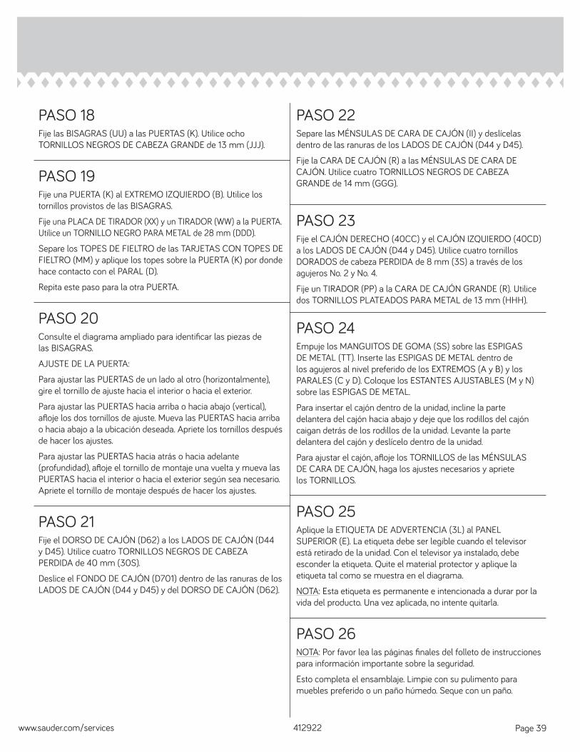
PASO 25Aplique la ETIQUETA DE ADVERTENCIA (3L) al PANEL SUPERIOR (E). La etiqueta debe ser legible cuando el televisor está retirado de la unidad. Con el televisor ya instalado, debe esconder la etiqueta. Quite el material protector y aplique la etiqueta tal como se muestra en el diagrama.
NOTA: Esta etiqueta es permanente e intencionada a durar por la vida del producto. Una vez aplicada, no intente quitarla.
412922www.sauder.com/services Page 39
PASO 26NOTA: Por favor lea las páginas fi nales del folleto de instrucciones para información importante sobre la seguridad.
Esto completa el ensamblaje. Limpie con su pulimento para muebles preferido o un paño húmedo. Seque con un paño.

412922 www.sauder.com/servicesPage 40
WARNINGPlease use your furniture correctly and safely. Improper use can cause safety hazards,
or damage to your furniture or household items. Carefully read the following safety information.Death or serious injury may occur when children climb on audio and/or video equipment furniture. A remote control or toys placed on the furnishing may encourage a child to climb on the furnishing and as a result may tip over onto the child. NEVER allow children to climb or play with the TV or furnishing supporting the TV. NEVER place toys, food, remote, etc. on top of the TV or TV furnishing. ALWAYS use either the safety hardware as instructed or other wall anchoring device.
Relocating audio and/or video equipment to furniture not specifi cally designed to support audio and/or video equipment may result in death or serious injury due to furniture collapse or over turning onto a child. NEVER place a TV on furniture that is not intended to support a TV. NEVER exceed the maximum size and weight of the TV shown in the instructions. Be sure to apply the TV warning label as shown in the instructions.
Overloading drawers and shelves may result in furniture that can break or sag, or tip-over which may result in injury. NEVER exceed the weight limits shown in the instructions. Place the heavier items on lower shelves as far back from the front as possible. Load the bottom surfaces fi rst to avoid top-heavy furniture.
Moving furniture that is not designed to be moved or equipped with casters may result in injury or damage to furnishings or personal property. ALWAYS unload shelves and drawers, starting with the top surfaces, before moving. NEVER push or pull furniture on carpet. Have a friend help lift properly to move and/or reposition it.

412922www.sauder.com/services Page 41
AVERTISSEMENTPrière d'utiliser le mobilier à bon escient et avec prudence. Une mauvaise utilisation
peut être à l'origine de risques d'accident ou peut endommager le mobilier et les articles ménagers.Lire attentivement l'information suivante sur la sécurité.
La mort voire de graves blessures peuvent se produire lorsque des enfants grimpent sur le meuble audio et/ou de matériel vidéo. Une télécommande ou des jouets placés sur les meubles peuvent encourager un enfant à grimper sur les meubles et risquent de les renverser sur l’enfant. NE JAMAIS laisser les enfants grimper sur ou jouer avec le téléviseur ou le meuble le supportant. NE JAMAIS placer de jouets, d'aliments, de télécommande, etc. sur le téléviseur ou le meuble télé. TOUJOURS utiliser soit la visserie de sécurité comme il l’est indiqué soit un autre dispositif d’ancrage mural.
Relocaliser du matériel audio et/ou vidéo sur un meuble non spécifi quement conçu pour supporter du matériel audio et/ou vidéo peut entraîner la mort voire de graves blessures l’eff ondrement du meuble ou son renversement sur un enfant. NE JAMAIS placer de téléviseur sur un meuble non conçu pour supporter un téléviseur. NE JAMAIS excéder la taille et le poids maximum du téléviseur indiqué sur les instructions. S’assurer d’apposer l'étiquette d’avertissement téléviseur comme il l'est indiqué sur les instructions.
Surcharger les tiroirs et tablettes peut provoquer la casse, l’aff aissement ou encore le renversement du meuble entraînant ainsi des blessures. NE JAMAIS excéder les limites de poids indiquées sur les instructions. Placer les articles plus lourds sur les tablettes inférieures aussi loin que possible de l'avant. Charger les surfaces inférieures en premier pour éviter un meuble trop lourd en haut.
Déplacer un meuble qui n’est pas conçu pour être déplacé ou qui est équipé de roulettes peut entraîner des blessures voire des dommages de meuble ou de matériel personnel. TOUJOURS décharger les tablettes et les tiroirs, en commençant par les surface supérieures, avant de déplacer le meuble. NE JAMAIS pousser ou tirer un meuble sur de la moquette. Demander à une autre personne de le soulever correctement pour le déplacer et/ou le repositionner.

412922 www.sauder.com/servicesPage 42
ADVERTENCIAPor favor use el mobiliario correcta y seguramente. El mal uso puede causar riesgos de seguridad o daño a las
unidades o artículos domésticos. Lea cuidadosamente la siguiente información de seguridad.Pueden suceder lesiones graves o la muerte cuando los niños se suben en los muebles de equipo de audio y/o video. Un control remoto o juguetes colocados en el mueble pueden alentar a un niño a subirse en el mueble y como resultado puede derribarse sobre el niño. NUNCA permita que los niños se suban o jueguen con el televisor o el mueble que sostiene el televisor. NUNCA coloque juguetes, alimentos, control remoto, etc. encima del televisor o el mueble del televisor. SIEMPRE utilice el soporte físico de seguridad según las instrucciones u otro dispositivo de anclaje en la pared.
La reubicación de equipos de audio y/o video a muebles que no estén específi camente diseñados para soportar equipos de audio y/o video puede resultar en muerte o lesiones graves debido al colapso de los muebles o al darse vuelta encima de un niño. NUNCA coloque un televisor en muebles que no estén diseñados para soportar un televisor. NUNCA exceda el tamaño y peso máximo del televisor indicado en las instrucciones. Asegúrese de aplicar la etiqueta de advertencia del televisor como se indica en las instrucciones.
El sobrecargar los cajones y estantes puede resultar en muebles que se puedan romper o colapsar o derribar, lo que puede resultar en lesiones. NUNCA exceda los límites de peso indicados en las instrucciones. Coloque los artículos más pesados en los estantes inferiores cuanto lejos de la parte delantera sea posible. Cargue las superfi cies inferiores primero para evitar muebles con la parte superior pesada.
El mover muebles que no estén diseñados para ser movidos o equipados con ruedas puede resultar en lesiones o daños al mueble o a los bienes personales. SIEMPRE descargue los estantes y cajones, empezando con las superfi cies superiores, antes de moverlo. NUNCA empuje ni tire de los muebles sobre una alfombra. Obtenga que un amigo le ayude a levantarlo correctamente para moverlo y/o reposicionarlo.

412922www.sauder.com/services Page 43
1. Sauder Woodworking Co. (Sauder®) provee cobertura de garantía limitada al comprador original de este producto por un período de cinco años, a partir de la fecha de compra, contra defectos en los materiales o de mano de obra en los componentes de muebles Sauder. Como es utilizado en esta Garantía, “defecto” signifi ca imperfecciones en los componentes que de manera fundamental afecta la utilidad del producto. Esta Garantía le permite a usted ciertos derechos legales, y usted también podría poseer otros derechos adicionales, los cuales varían de estado a estado. 2. No hay cobertura de garantía para defectos o estados que resulten del incumplimiento en seguir las instrucciones, la información o las advertencias sobre el ensamblaje del producto; del uso incorrecto o maltrato, del daño intencional, incendio, inundación, cambio o modifi cación del producto; o de la utilización del producto de manera contradictoria con el uso para el cual fue fabricado, ni por ningún estado que resulte del mantenimiento, limpieza o cuidado incorrecto o inadecuado. Tampoco no hay cobertura de garantía para los productos rentados o para cualesquiera productos comprados “de uso” o “como está”, en una venta de bienes embargados o en una venta por salirse del negocio, o comprados a un liquidador. 3. Como un recurso exclusivo bajo esta Garantía, Sauder (sólo a su opción) reparará, reemplazará o reembolsará el valor de cualquier componente defectuoso de mueble. Sauder puede requerir una confi rmación independiente de un defecto reclamado y una prueba de compra. Las piezas de repuesto serán garantizadas solamente por el período de tiempo que queda de la Garantía original. SAUDER NO TENDRÁ RESPONSABILIDAD por NINGÚN DAÑO INCIDENTAL O CONSECUENTE DE NINGÚN TIPO y todos dichos daños SE EXCLUYEN DE ESTA GARANTÍA, tales como pérdida de uso, desensamblaje, transportación, trabajo o daño a la propiedad en o cerca del producto. Algunos estados no permiten la exclusión o limitación de daños incidentales o consecuentes, en tales instancias la limitación o exclusión antes mencionada podría no ser aplicable a usted.
4. Esta Garantía sólo es aplicable a defectos garantizados que primeramente surjan y se informen a Sauder dentro del período de cobertura de garantía. La Garantía no puede ser transferida a propietarios o usuarios subsiguientes del producto, y ésta será inmediatamente invalidada en el caso que el producto sea revendido, transferido, arrendado o rentado a cualquier tercero u otra persona que no sea el comprador original. 5. NO HAY OTRA GARANTÍA APLICABLE A ESTE PRODUCTO. Bajo las leyes de ciertos estados, pueden no haber garantías implícitas de Sauder y se hace renuncia de responsabilidad de todas las garantías implícitas donde lo permita la ley, INCLUYENDO CUALQUIER GARANTÍA IMPLÍCITA DE MERCANTIBILIDAD O DE APTITUD PARA UN PROPÓSITO EN PARTICULAR. EN LA MEDIDA CUALQUIER GARANTÍA IMPLÍCITA ES APLICABLE, CUALESQUIERA GARANTÍAS IMPLÍCITAS, INCLUYENDO AQUELLA DE MERCANTIBILIDAD O DE APTITUD PARA UN PROPÓSITO EN PARTICULAR, SE LIMITAN EN DURACIÓN HASTA LA DURACIÓN DE ESTA GARANTÍA IMPLÍCITA o hasta el periodo mínimo permitido por la ley, la que sea más corta. Algunos estados no permiten limitaciones en cuanto a la duración de una garantía implícita, por eso la limitación arriba citada pueda no ser aplicable a usted. 6. Para solicitud de información o reclamación de Garantía, por favor, visite nuestro sitio Web www.sauder.com. Usted también puede contactar a Sauder llamando al 1.800.523.3987. Sauder puede solicitar que las reclamaciones sean presentadas por escrito a: Sauder Woodworking Co., 502 Middle Street, Archbold, OH 43502 USA. Por favor incluya su recibo de venta u otra prueba de compra y una descripción detallada del defecto del producto.
GARANTÍA LIMITADA DE 5 AÑOS
1. Sauder Woodworking Co. (Sauder®) off re une couverture de garantie limitée à l'acheteur initial du présent produit pendant une période de cinq ans à compter de la date d'achat contre tout défaut de matériaux ou de fabrication des composantes de mobilier Sauder. Le mot « défaut », tel qu’il est utilisé sous les termes de la présente garantie, comprend les imperfections des pièces qui empêchent substantiellement l’utilisation du produit. La présente garantie vous donne des droits légaux spécifi ques et il est possible que vous ayez des droits supplémentaires variant d’État en État ou de province en province.2. La présente garantie ne saurait couvrir les défauts ou conditions qui surviendraient à la suite du non respect des instructions, informations ou mises en garde de montage, d’une mauvaise utilisation ou d’un abus, d’un dommage intentionnel, d’un incendie, d’une inondation, d’une altération ou modifi cation du produit, d’une utilisation du produit allant à l’encontre de son usage prévu, ni aucune condition résultant d'une maintenance, d'un nettoyage ou d'un entretien inappropriés ou inadéquats. De plus, il n'existe aucune garantie pour les produits loués ou tous les produits achetés « d'occasion » ou « en l'état », dans le cadre d'une vente aux enchères ou de solde pour cessation de commerce, ou auprès d'un liquidateur.3. En tant que recours exclusif en vertu de la présente garantie, Sauder réparera, remplacera ou rembourser (sur sa seule décision) la valeur de toute composante de mobilier défectueuse. Sauder peut exiger une confi rmation indépendante du défaut revendiqué ainsi qu'une preuve d'achat. Les pièces de rechange seront garanties uniquement pendant la période restante de la garantie originale. SAUDER NE SERA EN AUCUN CAS RESPONSABLE de TOUT DOMMAGE ACCESSOIRE OU CONSÉCUTIF DE TOUTE SORTE et lesdits dommages sont EXCLUS DE LA PRÉSENTE GARANTIE, à savoir perte d'utilisation, démontage, transport, main d'œuvre ou dommages matériels sur ou à proximité du produit. Certains États ou provinces ne permettant pas l’exclusion ou la limite aux responsabilités pour dommages accidentels ou consécutifs, la limite ou l’exclusion ci -dessus peut ne pas être applicable.
4. La présente garantie ne s'applique qu'aux défauts garantis qui se produisent pour la première fois et qui sont signalés à Sauder dans les limites de couverture de la garantie. La garantie ne peut pas être transférée à des propriétaires ou utilisateurs subséquents du produit, et sera immédiatement invalidée dans le cas où le produit est revendu, transféré, loué sous bail ou loué à une tierce partie ou personne autre que l’acheteur original.5. IL N'EXISTE AUCUNE AUTRE GARANTIE EN VIGUEUR POUR LE PRÉSENT PRODUIT. En vertu des lois de certains États ou provinces, il ne peut y avoir de garanties implicites de la part de Sauder et toutes les garanties implicites, Y COMPRIS TOUTE GARANTIE IMPLICITE DE COMMERCIABILITÉ OU D'ADAPTATION À UN USAGE PARTICULIER sont déclinées partout où la loi l'autorise. DANS LA MESURE OÙ TOUTE GARANTIE IMPLICITE EST APPLICABLE, TOUTE GARANTIE IMPLICITE, Y COMPRIS TOUTE GARANTIE DE COMMERCIABILITÉ OU D'ADAPTATION À UN USAGE PARTICULIER, EST LIMITÉE À LA DURÉE DE LA PRÉSENTE GARANTIE EXPRESSE ou à la période minimum autorisée par la loi, la période la plus courte étant retenue. Certains États ne permettant pas que des limites soient imposées quant à la durée d’une garantie implicite, la limite ci-dessus peut donc ne pas être applicable.6. Pour toute question concernant la garantie ou toute demande de réclamation, consulter le site Web www.sauder.com. Il est également possible de contacter Sauder en composant le 1.800.523.3987. Sauder peut exiger de soumettre les demandes de réclamation sous garantie par écrit à : Sauder Woodworking Co., 502 Middle Street, Archbold, OH 43502 USA. Veuillez joindre votre ticket de caisse ou toute autre preuve d’achat ainsi qu’une description spécifi que du défaut de produit.
GARANTIE LIMITÉE DE 5 ANS
1. Sauder Woodworking Co. (Sauder®) provides limited warranty coverage to the original purchaser of this product for a period of fi ve years from the date of purchase against defects in materials or workmanship of Sauder furniture components. As used in this Warranty, “defect” means imperfections in components which substantially impair the utility of the product. This Warranty gives you specifi c legal rights, and you may also have other rights which vary from state to state.2. There is no warranty coverage for defects or conditions that result from the failure to follow product assembly instructions, information or warnings, misuse or abuse, intentional damage, fi re, fl ood, alteration or modifi cation of the product, or use of the product in a manner inconsistent with its intended use, nor any condition resulting from incorrect or inadequate maintenance, cleaning, or care. There is also no warranty coverage for rented products or any products purchased “used” or “as is”, at a distress or going-out-of business sale, or from a liquidator.3. As the exclusive remedy under this Warranty, Sauder will (at its sole option) repair, replace or refund the value of any defective furniture component. Sauder may require independent confi rmation of the claimed defect and proof of purchase. Replacement parts will be warranted for only the remaining period of the original Warranty. SAUDER SHALL HAVE NO LIABILITY for ANY INCIDENTAL OR CONSEQUENTIAL DAMAGES OF ANY KIND and all such damages are EXCLUDED FROM THIS WARRANTY, such as loss of use, disassembly, transportation, labor or damage to property on or near the product. Some states do not allow the exclusion or limitation of incidental or consequential damages, so the above limitation or exclusion may not apply to you.
4. This Warranty applies only to warranted defects that fi rst arise and are reported to Sauder within the warranty coverage period. The Warranty cannot be transferred to subsequent owners or users of the product, and it shall be immediately void in the event the product is resold, transferred, leased or rented to any third party or person other than the original purchaser.5. THERE ARE NO OTHER WARRANTIES APPLICABLE TO THIS PRODUCT. Under the laws of certain states, there may be no implied warranties from Sauder and all implied warranties, INCLUDING ANY IMPLIED WARRANTY OF MERCHANTABILITY OR FITNESS FOR A PARTICULAR PURPOSE are disclaimed where allowed by law. TO THE EXTENT ANY IMPLIED WARRANTIES ARE APPLICABLE, ANY IMPLIED WARRANTIES, INCLUDING ANY IMPLIED WARRANTY OF MERCHANTABILITY OR FITNESS FOR A PARTICULAR PURPOSE, ARE LIMITED IN DURATION TO THE DURATION OF THIS EXPRESS WARRANTY or the minimum period allowed by law, whichever is shorter. Some states do not allow limitations on how long an implied Warranty lasts, so the above limitation may not apply to you.6. For Warranty inquiries or claims, please visit our website www.sauder.com. You can also contact Sauder at 1.800.523.3987. Sauder may require Warranty claims to be submitted in writing to: Sauder Woodworking Co., 502 Middle Street, Archbold, OH 43502 USA. Please include your sales receipt or other proof of purchase and a specifi c description of the product defect.
5-YEAR LIMITED WARRANTY

Register your new product online
For immediate service, our website is available 24 hours per day, seven days per week, to order replacement parts, access assembly tips, register your product and view Sauder products. www.sauder.comCustomer Services in United States and Canada Monday through Friday – 9 a.m. to 5:30 p.m. ET (except holidays) 1-800-523-3987
Dear Valued Customer:
Thanks so much for choosing Sauder® furniture. I hope the purchase and assembly process was a positive experience and you feel good about the furniture you just built. If you need assistance or want to learn more, please contact our award-winning, Ohio-based customer service team at 800-523-3987 or Sauder.com.
My grandfather, Erie Sauder, founded the company in 1934 and later invented and patented the fi rst commercially successful ready-to-assemble tables. We strive to hold true to his core values of innovation, integrity, servanthood and stewardship.
Sauder products are made with environmentally responsible materials and world-class manufacturing processes. Our 2,000+ dedicated employees in Archbold, Ohio, along with our global manufacturing partners, are committed to providing you furniture with great value, style and quality.
From our family to you. Enjoy!
Kevin J. SauderPresident/CEO
So, how did it go? Set a world record for speed? Feeling good about yourself? Nice. Get social with it on any of these quality share sites.
General Conformity Certifi cate1. This certifi cate applies to the Sauder Woodworking Product identifi ed by this Instruction Book.2. This certifi cate applies to compliance of this product with the CPSC Ban on Lead-Containing Paint (16 CFR 1303).3. This product is manufactured by: Sauder Woodworking Company 502 Middle St. Archbold, OH 43502 419-446-27114. Date of Manufacture: __________________________
And don’t forget to rate and review your piece at Sauder.com in the product detail page.