Enter Document Name 10 - Reference...
287
Enter Document Name 10 - Reference Specification 19 Jun 2012
Transcript of Enter Document Name 10 - Reference...

Enter Document Name 10 - Reference Specification19 Jun 2012

Table of Contents
Title Page
GENERAL TECHNICAL REQUIREMENTSA90 5
CONSERVATORIESB12 8
PREFABRICATED FRAMED STRUCTURESB15 9
DEMOLITIONC20 10
CLEANING MASONRY AND CONCRETEC40 12
DAMP PROOF COURSE RENEWAL OR INSERTIONC45 14
CAVITY WALL TIE RENEWAL OR INSERTIONC46 15
FUNGUS/ BEETLE ERADICATIONC52 17
EXCAVATING AND FILLINGD20 18
UNDERPINNINGD50 22
IN SITU CONCRETEE10 23
FORMWORK FOR IN SITU CONCRETEE20 25
REINFORCEMENT FOR IN SITU CONCRETEE30 27
PRECAST CONCRETE FLOORS AND ROOF DECKSE60 28
BRICK AND BLOCK WALLINGF10 29
GLASS BLOCK WALLINGF11 31
NATURAL STONE RUBBLE WALLINGF20 32
NATURAL STONE ASHLAR WALLING AND DRESSINGSF21 33
CAST STONE ASHLAR WALLING AND DRESSINGSF22 35
ACCESSORIES AND SUNDRY ITEMS FOR BRICK BLOCK AND STONE WALLI...F30 37
PURPOSE MADE PRECAST CONCRETE SILLS, LINTELS, COPINGS AND FE...F31 41
STRAW BALE WALLING SYSTEMSF42 43
STRUCTURAL STEEL FRAMINGG10 45
ISOLATED STRUCTURAL METAL MEMBERSG12 48
CARPENTRY AND TIMBER FRAMINGG20 49
METAL PROFILED SHEET DECKINGG30 53
PATENT GLAZINGH10 54
RIGID SHEET CLADDINGH20 56
TIMBER WEATHERBOARDINGH21 57
PLASTICS WEATHERBOARDINGH22 58
FIBRE CEMENT PROFILED SHEET CLADDING AND COVERINGH30 59
METAL PROFILED SHEET CLADDING AND COVERINGH31 61
PLASTICS PROFILED SHEET CLADDING AND COVERINGH32 63
METAL COMPOSITE PANEL CLADDING AND COVERINGSH43 64
PLAIN ROOF TILINGH60 66
FIBRE CEMENT SLATINGH61 70
NATURAL SLATINGH62 74
SINGLE LAP ROOF TILINGH65 78
LEAD SHEET COVERINGSH71A 82
LEAD SHEET FLASHINGS AND WEATHERINGSH71B 86
ALUMINIUM STRIP OR SHEET COVERINGS AND FLASHINGSH72 92
COPPER STRIP OR SHEET COVERINGS AND FLASHINGSH73 97

ZINC STRIP OR SHEET COVERINGS AND FLASHINGSH74 102
STAINLESS STEEL STRIP OR SHEET COVERINGS AND FLASHINGSH75 107
CEMENTITIOUS MORTAR TANKING AND DAMP PROOFINGJ10 112
MASTIC ASPHALT TANKING AND DAMP PROOFINGJ20 114
MASTIC ASPHALT ROOFING INSULATION AND FINISHESJ21 116
LIQUID APPLIED TANKING AND DAMP PROOFINGJ30 120
LIQUID APPLIED WATERPROOF ROOF COATINGSJ31 121
FLEXIBLE SHEET WATERPROOFING AND DAMP PROOFINGJ40 125
REINFORCED BITUMEN MEMBRANE ROOF COVERINGSJ41 127
SINGLE LAYER POLYMERIC SHEET ROOF COVERINGSJ42 132
SHEET LININGS FOR SMALL POOLS AND PONDSJ44 135
PLASTERBOARD DRY LININGS FOR WALLS, PARTITIONS AND CEILINGSK10 136
RIGID SHEET FLOORING, SHEATHING, DECKING, SARKING, LININGS A...K11 140
TIMBER BOARD FLOORING DECKING SARKING LININGS AND CASINGSK20 145
WOOD STRIP OR BOARD FINE FLOORING OR LININGSK21 147
PANEL PARTITIONSK30 148
PANEL CUBICLES LININGS AND SCREENSK32 150
DEMOUNTABLE SUSPENDED CEILINGSK40 151
RAISED ACCESS FLOORSK41 154
WINDOWS ROOFLIGHTS SCREENS AND LOUVRESL10 156
DOORS/ SHUTTERS/ HATCHESL20 158
STAIRS LADDERS AND BALUSTRADESL30 160
GENERAL GLAZINGL40 161
CEMENT BASED LEVELLING AND WEARING SCREEDSM10 164
RESIN FLOORINGM12 167
CALCIUM SULFATE BASED SCREEDSM13 169
PLASTERED COATINGSM20A 170
RENDERED AND ROUGHCAST COATINGSM20B 173
INSULATION WITH RENDERED FINISHM21 176
STONE, QUARRY AND CERAMIC TILING OR MOSAICM40 177
WOOD BLOCK COMPOSITION BLOCK AND MOSAIC PARQUET FLOORINGM42 180
RUBBER, PLASTICS, CORK, LINO, AND CARPET TILING AND SHEETINGM50 182
DECORATIVE PAPERS AND FABRICSM52 185
PAINTING AND CLEAR FINISHINGM60 187
INTUMESCENT COATINGS FOR FIRE PROTECTION OF STEELWORKM61 191
GENERAL FIXTURES FURNISHINGS AND EQUIPMENTN10 193
GENERAL FIXTURES FURNISHINGS AND EQUIPMENTN11 194
SANITARY APPLIANCES AND FITTINGSN13 195
SIGNS AND NOTICESN15 197
PERMANENT ACCESS AND SAFETY EQUIPMENTN25 198
EXTERNAL SIGNAGE AND INTERPRETATIONN91 200
SUNDRY INSULATION AND PROOFING WORKP10 201
INJECTED CAVITY WALL INSULATIONP11 204
FIRE STOPPING SYSTEMSP12 205
UNFRAMED ISOLATED TRIMS SKIRTINGS AND SUNDRY ITEMSP20 206
DOOR AND WINDOW IRONMONGERYP21 207

TRENCHES, PIPEWAYS AND PITS FOR BURIED ENGINEERING SERVICESP30 209
HOLES, CHASES, COVERS AND SUPPORTS FOR SERVICESP31 212
KERBS, EDGINGS, CHANNELS AND PAVING ACCESSORIESQ10 213
GRANULAR SUB-BASES TO PAVINGSQ20 214
ASPHALT PAVINGSQ22 215
GRAVEL, HOGGIN AND WOODCHIP DRIVES AND PAVINGSQ23 216
INTERLOCKING BRICK OR BLOCK ROADS OR PAVINGSQ24 218
SLAB, BRICK, SETT, OR COBBLE PAVINGSQ25 220
TOPSOILINGQ28 223
SEEDING AND TURFINGQ30 224
EXTERNAL PLANTINGQ31 226
FENCINGQ40 229
SITE AND STREET FURNITURE AND EQUIPMENTQ50 234
RAINWATER DRAINAGE SYSTEMSR10 235
ABOVE GROUND FOUL DRAINAGE SYSTEMSR11 237
BELOW GROUND DRAINAGE SYSTEMSR12 239
LAND DRAINAGER13 247
GROUNDWATER PRESSURE RELIEF DRAINAGE SYSTEMSR16 249
SOAKAWAY AND SEPTIC TANK AND SEWAGE TREATMENT UNITSR17 250
FOUNTAINS AND WATER FEATURESS15 252
HOT AND COLD WATER SUPPLY SYSTEMSS90 253
HEATING SYSTEMST90 259
GENERAL VENTILATIONU10 265
GENERAL VENTILATIONU90 266
ELECTRICAL INSTALLATIONV90 267
ACCESS CONTROL SYSTEMSW40 272
INTRUSION AND HOLD-UP ALARM SYSTEMSW41 274
CLOSED CIRCUIT TELEVISION SYSTEMSW44 276
FIRE DETECTION AND ALARM SYSTEMSW50 277
LIFT SYSTEMSX90 278
PURPOSE MADE JOINERYZ10 280
PURPOSE MADE METALWORKZ11 281
PRESERVATIVE AND FIRE RETARDANT TREATMENTZ12 283
FIXINGS AND ADHESIVESZ20 284
MORTARSZ21 286
A90 GENERAL TECHNICAL REQUIREMENTSGENERAL
PrecedenceGeneral: Where, and to the extent that, documents conflict the following orders of precedence apply:
• Schedules of work override preliminaries, which override contract drawings, which override the Reference specification.
• Work sections of the Reference specification override A90.
Conflict in the documents: Give notice.
Definitions and interpretations - generalEmployer's Representative: The person nominated in the Contract as Employer's Representative, Architect, ContractAdministrator or Project Manager.Reference specification: Not all clauses in the Reference specification apply to this project. If in doubt about theapplicability of a clause, obtain instructions.Communication: When required to communicate – including advise, inform, submit, give notice, instruct, agree, confirm,seek or obtain information, consent or instructions, or make arrangements – do so in writing to the Employer'sRepresentative.Responses from the Employer's Representative: Do not proceed until response has been received.
Definitions and interpretations – products and workRemove:
• Disconnect, dismantle as necessary and take out the designated products or work and associated accessories,
fastenings, supports, linings and bedding materials. Dispose of unwanted materials.
• Excludes taking out and disposing of associated pipework, wiring, ductwork or other services.
Keep for reuse:
• Do not damage designated products or work. Clean off bedding and jointing materials.
Make good:
• Execute local remedial work to designated work. Make secure, sound and neat.
• Excludes redecoration and/ or replacement.
Repair:
• Execute remedial work to designated products. Make secure, sound and neat.
• Excludes redecoration and/ or replacement.
Refix: Fix removed products.Replace: Supply and fix new products matching those removed. Execute work to match original new state of thatremoved.Ease: Adjust moving parts of designated products or work to achieve free movement and good fit in open and closedpositions.Match existing: Provide products and work of the same appearance and features as the original, excluding ageing andweathering. Make joints between existing and new work as inconspicuous as possible.
DocumentsCurrency: References to published documents are to the editions, including amendments, current on the date of theInvitation to tender.Services drawings: Diagrammatic, except to the extent that figured dimensions are given or calculable.Dimensions: Do not rely on scaled dimensions.
COMPLIANCE
Compliance generallySubmittals, samples, inspections and tests: Undertake to suit the Works programme. Do not conceal, or proceed with,affected work until compliance with requirements is confirmed.Compliance with proprietary specifications: Retain on site evidence that the proprietary product specified has beensupplied.Compliance with performance specifications: Submit evidence of compliance, including test reports indicating propertiestested, pass/ fail criteria, test methods and procedures, test results, identity of testing agency, test dates and times,identities of witnesses, and analysis of results.
Design and production documentationDesign compliance: Submit certification that design complies with documented requirements.Documentation:
• Draft: Submit complete design and production documentation.
• Final: Submit sufficient copies for distribution to affected parties. Keep at least one copy on site.Space requirements: Check space requirements of products or work indicated diagrammatically in the contractdocuments. Submit a report on consequent variations needed to the design.Drawings: Include dimensions.
Authorities and statutory undertakersApprovals: Submit evidence of approvals of relevant authorities and statutory undertakers.
Product samplesComplying samples: Retain in good, clean condition on site.

PRODUCTS AND EXECUTION
General qualityProducts generally: New. Proposals for recycled products will be considered.
• Supply of each product: From the same source or manufacturer.
• Whole quantity of each product required to complete the Works: Consistent kind, size, quality and overall appearance.
• Product tolerances: Where critical, measure a sufficient quantity to determine compliance.
Execution generally: Fix, apply, install or lay products securely, accurately, plumb, neatly and in alignment.
• Colour batching: Do not use different colour batches where they can be seen together.
• Dimensions: Check on-site dimensions.
• Finished work: Not defective, e.g. not damaged, disfigured, dirty, faulty, or out of tolerance.
SizesGeneral dimensions: Nominal.Cross section dimensions of timber: Finished dimensions.
SubstitutionProducts: If an alternative product to that specified is proposed, obtain approval before ordering the product.Work: If alternative work to that specified is proposed, obtain approval before execution.Reasons: Submit reasons for the proposed substitution.Documentation: Submit relevant information, including:
• manufacturer and product reference;
• cost;
• availability;
• relevant standards;
• performance;
• function;
• compatibility of accessories;
• proposed revisions to drawings and specification;
• compatibility with adjacent work;
• appearance; and
• copy of warranty/ guarantee.
Alterations to adjacent work: If needed, advise scope, nature and cost.Manufacturers' guarantees: If substitution is accepted, submit.
Incomplete documentationGeneral: Where and to the extent that products or work are not fully documented, they are to be:
• Of a kind and standard appropriate to the nature and character of that part of the Works where they will be used.
• Suitable for the purposes stated or reasonably to be inferred.
Manufacturers' recommendationsGeneral: Comply with manufacturer's current printed recommendations and instructions.Changes to recommendations or instructions since close of tender: Submit details.Manufacturers' current recommendations and instructions: Keep copies on site.Ancillary products and accessories: Use those supplied or recommended by main product manufacturer.Agrément certified products: Comply with limitations, recommendations and requirements of relevant valid certificates.
Defects in existing workReporting undocumented defects: When discovered, immediately give notice. Do not proceed with affected related workuntil response has been received.Documented remedial work: Do not execute work which may:
• hinder access to defective products or work; or
• be rendered abortive by remedial work.
Accuracy, appearance and fitTolerances and dimensions: If likely to be critical to execution or difficult to achieve, as early as possible either:
• submit proposals; or
• arrange for inspection of appearance of relevant aspects of partially finished work.
General tolerances (maximum): To BS 5606, tables 1 and 2.Structural floor design level tolerances (maximum):
• Floors which are to be self-finished, and floors to receive sheet or tile finishes directly bedded in adhesive: ±10 mm.
• Floors to receive dry board/ panel work with little or no tolerance on thickness: ±10 mm.
• Floors to receive fully bonded screeds/ toppings/ beds: ±15 mm.
• Floors to receive unbonded or floating screeds/ beds: ±20 mm.

Services runsGeneral: Provide adequate space and support for services, including unobstructed routes and fixings.Services inaccessible after installation: Submit proposals for future location and identification of runs and fittings.Fixing of services: Submit typical details of locations, types and methods of fixing of services to fabric.
SparesGeneral: Supply designated spares in their original packaging.

B12 CONSERVATORIESGENERAL
Cross-referenceGeneral: Read with A90 General technical requirements.
PRODUCTS
Aluminium alloy framing sectionsStandard: To relevant parts of BS EN 515, BS EN 573, BS EN 755-9 and BS EN 12020.Alloy, temper and thickness: Suitable for the application and specified finish.Structural members: To BS EN 1999-1-1 (Eurocode 9), or BS 8118-2 where agreed.
PVC-U framing sectionsStandard: To BS EN 12608 (white or near white profiles) or BS 7722 (wood grain or surface covered extrusions).
Wood framing sectionsWood: Generally to BS EN 942.Appearance class: To BS EN 942.Moisture content on delivery: 13–19%.
Steel sectionsSteel:
• Angles, channels, I-beams and columns, tee sections and plates: To BS EN 10025-2.
• Hollow sections: To BS EN 10210-1.
Grade:
• Internal use: S275JR.
• External use: S275J0.Hot dip galvanizing: To BS EN ISO 1461.Zinc spray coating: To BS EN ISO 2063.
Glass generallyStandards: To BS 952-1 and relevant parts of:
• BS EN 572-1 and -2 for basic soda lime silicate glass.
• BS EN 1863-1 for heat strengthened soda lime silicate glass.
• BS EN 12150-1 for thermally toughened soda lime silicate glass.
• BS EN ISO 12543-1, -3, -4, -5 and -6 for laminated glass and laminated safety glass.
Panes/ sheets: Free from obvious scratches, bubbles, cracks, rippling, dimples and other defects.
• Edges: Generally undamaged. Shells and chips not more than 2 mm deep and extending not more than 5 mm across
the surface are acceptable if ground out.
Insulating glass unitsStandard: To BS EN 1279-1.
Plastics glazing sheetCondition: Free from scratches, edge splits and other defects.
EXECUTION
GeneralWorkmanship generally: To provide a secure weathertight installation.Fabrication: Machine cut and drill components in the workshop wherever possible.Installation of glazing: To BS 6262-4.Materials:
• Compatibility: Glass/ plastics, surround materials, sealers, primers and paints/ clear finishes to be used together to be
compatible. Avoid contact between glazing panes/ units and alkaline materials such as cement and lime.
• Protection: Keep materials dry until fixed. Protect insulating glass units and plastics glazing from the sun and other heatsources.
• Protective coverings to panes: Carefully peeled back from edges and trimmed off to facilitate glazing. Remainder
retained in place until completion unless instructed otherwise.Fixings: Concealed unless specifically agreed otherwise.
IronmongeryFixing: Assemble and fix carefully and accurately using fasteners with matching finish supplied by ironmongerymanufacturer. Do not damage ironmongery and adjacent surfaces.Checking/ adjusting/ lubricating: Carry out at Completion and ensure correct functioning.
DocumentationManuals: Provide information detailing instructions for repair and modification and level of expertise required.

B15 PREFABRICATED FRAMED STRUCTURESGENERAL
Cross-referenceGeneral: Read with A90 General technical requirements.
Pre-completion testingAir permeability: See Preliminaries A33/570.Continuity of thermal insulation: See Preliminaries A33/580.Resistance to passage of sound: See Preliminaries A33/590.
PRODUCTS
Timber frame designStandard: In accordance with BS EN 1995-1-1 and -1-2 (Eurocode 5), or BS 5268 -2 to -7 where agreed.
EXECUTION
Information from manufacturerPrior to fabrication of frame, manufacturer to provide:
• Drawings showing all construction details, including connections and manufactured tolerances.
• Risk assessments for the installation and construction process.
• Installation instructions including training requirements for installers.
• Requirements for storage of materials.
TransportationGeneral: Handling, lifting and transportation must not cause damage, or impair the intended performance of elements or components when subsequently erected.
DeliveryInspection: Upon delivery inspect all materials to ensure they are free from damage and that the required accuracy of erection can be achieved.
StorageSupport: So as not induce excessive stress into the components.Protection: Prevent the ingress of water.
Supporting structureSurvey: Before commencing installation, carry out survey sufficient to verify that required accuracy of erection can beachieved.
ErectionLifting, positioning, fixing:
• Do not drag units.
• Lift units from manufacturer's designated points only.
• Provide temporarily support, as required.
AssemblyFraming components: Cut squarely or as required for an angular fit against abutting members.Fixings: Size and pattern as determined by structural calculation.Splices: Not permitted except where specifically designed.Anchor bolts and straps: Correctly positioned at all locations shown on the drawings.Insulation: Ensure continuity.
Accuracy of erectionFinished appearance: Frames must be square, regular, true to line, level and plane.

C20 DEMOLITIONGENERAL
Cross-referenceGeneral: Read with A90 General technical requirements.
EXECUTION
Report and method statementContent: Cover relevant matters under CDM as outlined in Health and Safety Executive publications L144 'Construction(Design and Management) Regulations 2007 Approved Code of Practice' and 'Health and Safety in Construction' HS(G)150, and as follows:
• Condition survey of structures including neighbouring properties, boundaries, etc. Also including the presence, or
anticipated presence, of protected species (bats, barn owls, breeding birds, and others listed in any relevantbiodiversity plan).
• Deconstruction and/ or demolition methods of the structures.
• Site waste management plan, if applicable.
• Considerations arising from adoption of the Demolition Protocol, if applicable.
• Removal, transportation and disposal methods of toxic or hazardous materials, including gypsum based products and
asbestos-containing materials that do not require a licence for removal (e.g. certain types of textured coatings).
• Type and location of adjoining or surrounding premises which may be adversely affected by the work.
• Identification and location of services above and below ground.
• Storage and protection of reclaimed materials for use either on or off site.
Bench marksUnrecorded bench marks and other survey information: Give notice when found. Do not move or destroy.
Services regulationsWork carried out to or which affects new or existing services: Carry out in accordance with Byelaws or Regulations of therelevant Statutory Authority.
Location and marking of servicesStandard: in accordance with National Joint Utilities Group (NJUG) Volume 1 'Guidelines on the positioning and colour coding of underground utilities' apparatus'.
Drains in useDrains, manholes, inspection chambers, gullies, vent pipes and fittings still in use: Protect. Keep free of debris andspillages.Damage: Make good damage arising from demolition work. Leave clean and in working order at completion.
Bypass connectionsServices to occupied areas of the same and adjoining properties: Maintain continuity.Shutdown: Give 72 hours (minimum) notice to occupiers if shutdown is necessary during changeover.
Services which are to remainDamage: Give notice and notify service authority or owner of damage arising from the execution of the works.Repairs: Complete as directed, and to the satisfaction of the service authority or owner.
WorkmanshipDemolition or deconstruction of structures: In accordance with BS 6187.Site staff responsible for supervision and control of the work: Experienced in assessment of risks involved and methods of demolition or deconstruction to be used.Operatives: Appropriately skilled and experienced for the type of work and holding, or in training to obtain, relevant CITBCertificates of Competence.
Gas or vapour risksFire or explosion caused by gas or vapour: Prevent.
Dust and mudGeneral: Reduce dust by periodically spraying demolition works with an appropriate wetting agent. Keep neighbouringroads and footpaths clear of mud and debris.
Health hazardsHealth hazards associated with vibration, dangerous fumes and dust arising during demolition: Protect site operatives andgeneral public.
Removal of asbestos-containing materialsPlanning and execution: To HSE publications L127 'The Management of asbestos in non-domestic premises' and L143'Work with materials containing asbestos'.
Adjoining propertyTemporary support and protection: Provide. Maintain and alter as necessary as work progresses.Damage: Minimize. Promptly repair.
• Leave no unnecessary or unstable projections.
• Make good to ensure safety, stability, weather protection and security.Support to foundations: Do not disturb.Defects exposed or becoming apparent: Give notice.
Structures to be retainedParts to be retained: Protect.Cutting away and stripping out: Minimize. Carry out with care.Amount of making good: Minimize.
Partly demolished structuresGeneral: Leave in stable condition, with adequate temporary support at each stage to prevent uncontrolled collapse. Keepsafe outside of working hours.Temporary works: Prevent debris from overloading.Unauthorised persons: Prevent access.
Dangerous openingsGeneral: Illuminate and protect. Keep safe outside of working hours.
Unforeseen hazardsUnrecorded voids, tanks, chemicals, etc. discovered during demolition: Give notice.Methods for safe removal, filling etc: Submit details.

C40 CLEANING MASONRY AND CONCRETEGENERAL
Cross-referenceGeneral: Read with A90 General technical requirements.
PRODUCTS
Plain poulticesSoftening agent: Deionized water.
Surface biocidesTypes: Registered by the Health and Safety Executive (HSE) and listed on the HSE website under non-agriculturalpesticides.Compatibility with surface: Free from staining or other harmful effects.
Water sprayNozzles: Position and direction adjustable, relative to surfaces and profiles.
EXECUTION
GeneralStandard: In accordance with BS 8221-1.
Removal of fittingsTiming: Before commencement of cleaning work.Disturbance to surfaces: Minimize.
ProtectionSurfaces not designated for cleaning: Prevent damage, including marking and staining.Openings: Prevent ingress of water, cleaning agents and detritus.
• Vents and grilles: Seek instructions before sealing.
Temporary mechanical fastenings:
• In masonry: Locate in joints.
• In other surfaces: Seek instructions.
Control and disposal of wash water and detritusDisposal: Safely. Obtain approvals from relevant Authority.Control of wash water: Collect and divert to prevent ingress and damage to building fabric and adjacent areas.Above and below ground drainage systems: Keep free from detritus and maintain normal operation.
Cold weatherCleaning procedures using water: Do not use when air temperature is at or below 5°C.
• Damp surfaces: Protect from frost.
Chemical cleaning agents: Do not use when surface temperatures are below those recommended by manufacturer.
Cleaning generallyOperatives: Appropriately trained and experienced for each type of cleaning work.
• Evidence of training: Submit on request.Control of cleaning: Confine cleaning processes and materials to designated areas. Prevent wind drift.Detritus: Remove regularly. Dispose of safely.Monitoring: Frequently check results of cleaning compared to approved trial samples. If results established by trials are notachieved, seek instructions.Modifications to cleaning methods and materials: Seek instructions.
Record of cleaning worksWritten report: Record cleaning methods and procedures used for each type of surface and deposit.Content: Relevant attributes of cleaning methods used including:
• Equipment and settings.
• Dwell times.
• Number of applications.
• Ambient temperatures.
Submission: At completion of cleaning works.
Trial samplesRecords: Maintain written records for each trial area, including cleaning methods and conditions, to enable replication of results elsewhere.
Removal of loosely adhered depositsTiming: Before commencement of other cleaning methods.Surfaces: Prevent damage, including abrasion.

Biocide applicationPreparation: Dampen dry growths and remove loose growths.Surfaces: Prevent damage, including abrasion.Biocide treatment: Appropriate solutions to kill growths and inhibit further growths.
• Dead growths: Remove.
Abrasive blocksTypes: Suitable grades of carborundum or gritstone.Application: Lubricate with water. Remove detritus.Abrasive power tools: Prohibited.
Abrasives cleaningSurfaces: Minimize abrasion.
• Ingrained deposits: Seek instructions.
Equipment settings (including nozzle type and distance from surface): Adjust regularly to achieve optimum cleaningperformance for each surface.Detritus: Remove with clean water.
Water spray cleaning (mounted nozzles)Surfaces: Minimize water run-off. Prevent damage.Adjustment of washing cycle and nozzle positions: Regularly to achieve optimum cleaning performance.
Pressurized water cleaningSurfaces: Prevent damage.Equipment settings (including nozzle type and distance from surface): Adjust regularly to achieve optimum cleaningperformance for each surface.
Steam cleaningSurfaces: Prevent damage.Equipment settings (including nozzle type and distance from surface): Adjust regularly to achieve optimum cleaningperformance for each surface.
Testing pH values for chemical cleaningpH indicator: To distinguish pH values between 1–14.Testing before cleaning:
• Clean rinsing water, wetted surfaces and joints: Test for pH. Record as 'control' values.
Testing after water rinsing and neutralization:
• Wetted surfaces and joints: Record pH values.
• Acceptance criteria: Seek instructions.
Chemical cleaningSurfaces: Prevent damage, including discolouration, bleaching and efflorescence.Product variables (including concentrations, dwell times and number of applications): Adjust for each surface to achieveoptimum cleaning performance.Application: To wetted surfaces.
• Drying out: Prevent unless recommended otherwise by cleaning product manufacturer.
Removal of chemicals and neutralization: As recommended by product manufacturer, including rinsing with clean water.
• Additional treatment: Where water rinsing is insufficient to neutralize surface, apply compatible neutralizing agent.
• Surfaces and joints: Minimize absorption of chemicals. Prevent damage, including abrasion.
Plain poulticingSurfaces: Prevent damage.Application: To wetted surfaces. Maintain contact with surfaces as poultice dries out. Reinforce poultice as necessary.
• Drying: Prevent excessively rapid or localized drying out.Spent poultice material: Do not reuse.
Bird preventive devicesGenerally: Achieve an effective deterrent to roosting birds.Fasteners and adhesives: Compatible with building components and substrate.Timing: Coordinate with other related trades.Thermal and building movement: Allow for, where appropriate.
• Movement joints: Do not bridge.Roost inhibitors, nets and mesh screens: Correctly fitted and tensioned.
C45 DAMP PROOF COURSE RENEWAL OR INSERTIONGENERAL
Cross-referenceGeneral: Read with A90 General technical requirements.
Survey reportContent:
• Building defects causing damp or rising damp.
• Extent of rising damp. Determine using methods recommended in the Property Care Association (PCA) 'Code of
Practice for the installation of remedial damp proof courses in masonry walls', clause 6.
• Suitability of walls for treatment by proposed dpc system.
• Features which would prevent the installation of an effective dpc.
EXECUTION
Exposed masonryHeavily salt contaminated bricks or blocks: Give notice if revealed in the substrate.
Fungal and beetle attack to timber sectionsReport occurrences.
Sources of dampGive notice if built-in timbers, structural deficiencies or additional sources of damp are revealed.
Preparatory workPositions of dpcs not shown on drawings: Submit proposals.
Chemical dpc systemInstallation: To BS 6576 by a firm approved by dpc system manufacturer.
Mortar mix to exposed injection holesApproval of appearance: Obtain for first few holes before completing the remainder.

C46 CAVITY WALL TIE RENEWAL OR INSERTIONGENERAL
Cross-referenceGeneral: Read with A90 General technical requirements.
EXECUTION
Information to be provided with tenderSite monitoring and recording procedures: Submit proposals.
• Records: To be available for inspection during the course of the works.
Insurance backed guarantee for wall tie installation: Submit details, including:
• Terms and conditions.
• Period of cover from Practical Completion.
• Method of maintaining the guarantee should the installer cease trading.
• Extent of consequential losses underwritten by the guarantee.
Initial site testing of proof loads for wall tiesTiming: Before commencing wall tie installation.Tensile proof loads of wall tie fixings:
• General: Do not test wall ties until they have been installed for the appropriate periods recommended by the wall tiemanufacturer.
• Locations: Submit proposals.
• Testing: Give adequate notice.
• Test failures: Obtain instructions.
• Completion of satisfactory testing: Submit results.
Proof load testing of wall ties during installationTiming: During installation and before making the external leaf connections.Tensile proof loads of wall tie fixings:
• General: Do not test wall ties until they have been installed for the appropriate periods recommended by the wall tie
manufacturer.
• Testing: Give adequate notice.
• Test failures:
First sample set failure rate exceeds 10%: Repeat the proof test on a further sample set.Combined failure rate of both sample sets exceeds 10%: Obtain instructions.Ties that fail proof load test: Replace in suitably adjacent location and retest.
• Completion of satisfactory testing: Submit results.
Installation of wall tiesMasonry:
• Stable at all times during wall tie installation.
• Formation of holes: Minimize.
• Cavities: Clear and free from debris.
• Fixing holes: Clean.
Wall ties:
• Installation: Accurately and securely.
• Drips: Centred on cavity.
• Expansion anchor fixings: Set to the correct torque.
• Bonded fixings: Thoroughly grouted.
Facework: Keep clean.
Removing masonry unitsAdjacent masonry:
• Joints: Do not damage or widen.
• Old mortar: Remove.
• Cavities: Keep clean.
Units for reuse:
• Removal of units: In one piece. Clean and set aside for reuse.
• Units unsuitable for reuse: Obtain instructions.
Core drilling masonry with rendered finishDrilling: Carefully and accurately to provide access to existing ties.
Removal of existing wall ties from internal leafWall ties: Remove carefully and completely.Internal leaf/ finishes. Minimize disturbance.
Removal of existing wall ties from external leafWall ties:
• Flexible wire ties: Crop or bend down against face of internal leaf.
• Rigid ties: Crop against face of internal leaf.
Internal leaf/ finishes. Do not disturb.
Replacing masonry unitsMortar: As section Z21.Mortar joints: Control suction. Lay units on full bed and fully fill vertical joints.Cavities: Keep clean.
Isolating wall ties in external leafInstallation:
• Wall tie: End free from mortar, dust and debris.
• Sleeve: Fit accurately.
• Front edge of sleeve: Recess 20 mm (minimum) from face of masonry.
Mortar: As section Z21.Joints: Control suction. Fully fill with mortar.
• Profile: Finished neatly to match existing.
Facework: Keep clean.
Making good insertion/ inspection holes in external leafInsertion/ inspection holes in external leaf: Make good.Mortar mixes: To approval.
• Colour and texture: To match existing masonry units/ joints.
Insertion/ Inspection holes: Clean and fully filled with repair mortar.
• Finish: Neat and flush.
Making good external renderPatches where masonry units removed:
• Form undercut edges. Remove dust and debris. Dampen to control suction where necessary.
• Apply render coats firmly. Finish flush with existing render.
Retouching decorative finishes to external leafRepairs: Retouch carefully with compatible paint. Blend with existing surrounding finish.
Repointing cracked jointsJoints:
• Existing mortar: Remove carefully. Do not damage adjacent masonry or widen joints.
• Recess to receive pointing: Neat and square, of depth not less than twice the thickness of the joint.
Remove dust and debris.Mortar: As section Z21.Repointing: Control suction. Fully fill joints with mortar.
• Profile: Finish neatly to match existing adjacent joints.
Facework: Keep clean.
DocumentationSubmit:
• Statement of quality control checks.
• Certificate of Guarantee.
C52 FUNGUS/ BEETLE ERADICATIONGENERAL
Cross-referenceGeneral: Read with A90 General technical requirements.
PreparationFurnishings/ components/ finishes within treated areas: Prevent staining and other adverse effects.Water supplies: Do not contaminate.Electrical equipment and supplies: Isolate circuits as required and prevent ingress of treatment fluids.Cleanliness: Remove loose material, dust and debris from surfaces to be treated.
PRODUCTS/ TREATMENTS
Preservatives/ fungicidesType: Registered by the Health and Safety Executive (HSE) and listed in HSE publication 'Guide to Pesticides'.Proprietary preservatives selected by contractor: Submit proposals.
Heat treatmentStandard: PD CEN/TS 15003 Durability of wood and wood-based products – Criteria for hot air processes for curativeuses against wood destroying organisms.
EXECUTION
Survey reportContents:
• Sources and extent of dampness.
• Nature and extent of infestation/ decay.
• Site conditions and restrictions likely to affect execution of the work, including the presence of bats, barn owls, breeding
birds and other protected species. Restrictions imposed by biodiversity action plans.
• Proposed eradication treatment.
• Nature and extent of removal/ replacement of building fabric required.
• Work consequent upon treatment.
Additional workWork shown to be necessary by contractor's survey: Submit proposals.
Opening up/ cutting out/ removal of existing building fabricExtent: Submit proposals.Retained building fabric: Maintain stability and do not damage.
Drying out of building fabricDrying conditions: Establish as soon as possible.Methods: Submit proposals for permanent natural ventilation and for artificial methods.
Dry rotFruiting bodies: Do not disturb. Spray with fungicide or heat treat.
• Inspection: Give notice.
• Removal: Remove carefully. Clean down surfaces.
Infected materials: Remove immediately and dispose of safely at a tip approved by a waste regulation authority. Preventcontamination of other parts of building.
Salvaged materialSound, uninfected materials: Give notice before reusing/ recycling.
Preservatives/ fungicidesApplication: In accordance with statutory conditions given on product labels.
Drilling timber for injection of preservativesSizes and location of holes: Submit proposals.Approval of appearance: Obtain approval of first few holes before completing remainder.
GuaranteeType: Insurance backed. Administered by an independent insurance protection company.Guarantee period (minimum): 20 years from completion of installation.Documentation: Provide certificates/ guarantees at completion of treatment.

D20 EXCAVATING AND FILLINGGENERAL
Cross-referenceGeneral: Read with A90 General technical requirements.
PRODUCTS
Herbicide for treating topsoil before strippingType: Suitable translocated nonresidual herbicide.
Proposed fill materialsDetails: Prior to commencing filling, submit full details and test reports of proposed fill materials demonstrating compliancewith specification, including:
• Imported fill: Type and source.
• Material excavated on site: Proposals for processing and reuse.
Hazardous, aggressive or unstable fill materialsGeneral: Do not use fill materials which would, either in themselves or in combination with other materials or ground water,give rise to a health hazard, damage to building structures or instability in the filling.Do not use material that is:
• Frozen or containing ice.
• Organic.
• Contaminated or noxious.
• Susceptible to spontaneous combustion.
• Likely to erode or decay and cause voids.
• With excessive moisture content, slurry, mud or from marshes or bogs.
• Clay of liquid limit exceeding 80 and/ or plasticity index exceeding 55.
• Defined in Highways Agency (HA) publication 'Manual of contract documents for highway works: Volume 1:
Specification for highway works', clause 601 as 'Unacceptable materials'.
Frost susceptibility of fill materialsGeneral: Fill must not be frost-susceptible as defined in 'Specification for highway works', clause 801.Test reports: If the following fill materials are proposed, submit a laboratory report confirming they are not frost-susceptible:
• Fine grained soil with a plasticity index less than 20%.
• Coarse grained soil or crushed granite with more than 10% retained on a 0.063 mm sieve.
• Crushed chalk.
• Crushed limestone fill with average saturation moisture content in excess of 3%.
• Burnt colliery shale.Frost-susceptible fill: May only be used within the external walls of buildings below spaces that will be heated. Protect fromfrost during construction.
Compacted fill for landscape areasFill: Material capable of compaction by light earthmoving plant.
Highways Agency Type 1 granular fillFill: To 'Specification for highway works', clause 803:
• Crushed rock (other than argillaceous rock).
• Crushed concrete.
• Recycled aggregates.
• Crushed non-expansive slag.
• Well-burnt non-plastic colliery shale.
Highways Agency Type 2 granular fillFill: To 'Specification for highway works', clause 804:
• Crushed rock (other than argillaceous rock).
• Crushed concrete.
• Crushed non-expansive slag.
• Well-burnt non-plastic colliery shale.
• Natural gravel.
• Natural sand.

Hardcore fillFill: Granular material, free from excessive dust, well graded, passing a 75 mm BS sieve, 10% (minimum) fines value of 50kN when tested in a soaked condition to BS 812-111. In each layer only one of the following groups:
• Crushed rock (other than argillaceous rock) or quarry waste with not more binding material than is required to help hold
the stone together.
• Crushed concrete, crushed brick or tile, free from plaster, timber and metal.
• Recycled aggregates.
• Crushed non-expansive slag.
• Gravel or hoggin with not more clay content than is required to bind the material together, and with no large lumps of
clay.
• Well-burnt non-plastic colliery shale.
• Natural gravel.
• Natural sand.
Venting hardcore layerFill: Clean granular material, well graded, passing a 75 mm BS sieve but retained on a 20 mm BS sieve. In each layer onlyone of the following groups:
• Crushed hard rock.
• Crushed concrete, crushed brick or tile, free from plaster, timber and metal.
• Recycled aggregates.
• Gravel.
Sand blindingSand for blinding: To BS EN 12620, grade 0/4 or 0/2 (MP).Alternative fine materials: Submit proposals.
EXECUTION
Site clearanceTiming: Before topsoil stripping, if any.General: Clear site of rubbish, debris and vegetation. Do not compact topsoil.
Removing small trees, shrubs, hedges and rootsSafety: Comply with HSE/ Arboriculture and Forestry Advisory Group Safety guides.
Felling large treesSafety: Comply with HSE/ Arboriculture and Forestry Advisory Group Safety Guides.Felling: As close to the ground as possible.Work near retained trees: Take down trees carefully in small sections to avoid damage to adjacent trees that are to beretained, where tree canopies overlap and in confined spaces generally.
Stripping topsoilGeneral: Before commencing general excavation or filling, strip topsoil from areas where there will be regrading, buildings,pavings/ roads and other areas shown on drawings.Depth of topsoil difficult to determine: Give notice.Around trees: Do not remove topsoil from below the spread of trees to be retained.
Handling topsoilAggressive weeds:
• Give notice and obtain instructions before moving topsoil containing aggressive weeds included in the Weeds Act,
section 2 or the Wildlife and Countryside Act, Schedule 9, part II.
• Minimize disturbance, trafficking and compaction.
Contamination: Do not mix topsoil with the following:
• Subsoil, stone, hardcore, rubbish or material from demolition work.
• Oil, fuel, cement or other substances harmful to plant growth.
• Other grades of topsoil.
Multiple handling: Keep to a minimum. Use topsoil immediately after stripping.Wet conditions: Handle topsoil in the driest condition possible. Do not handle during or after heavy rainfall or when topsoilis wetter than the plastic limit as defined by BS 3882, Annex N2.
Adjacent excavationsProximity: Where an excavation encroaches below a line drawn at an angle from the nearest formation level of another higher excavation, the lower excavation, all work within it and backfilling thereto must be completed before the higher excavation is made.
• Angle of line from horizontal: 45° for stable soils, 30° for wet clays.

Permissible deviations from formation levelsBeneath mass concrete foundations: ±25 mm.Beneath ground bearing slabs and reinforced concrete foundations: ±15 mm.Embankments and cuttings: ±50 mm.Ground abutting external walls: ±50 mm, but finished level must be at least 150 mm below dpc.
Inspecting formationsGive notice: Make advance arrangements for inspection of formations.Preparation: Just before inspection remove the last 150 mm of excavation. Trim to required profiles and levels, andremove loose material.Formations: Seal with concrete within 4 hours of inspection.
FoundationsGive notice if:
• A natural bearing formation of undisturbed subsoil is not obtained at the depth shown on the drawings; or
• The formation contains soft or hard spots or highly variable material.
Trench fill foundationsExcavation: Form trench down to formation in one operation.Safety: Prepare formation from ground level.Inspection of formations: Give notice before excavating.Shoring: Where inspection of formation is required, provide localised shoring to suit ground conditions.Concrete fill: Place concrete immediately after inspection and no more than four hours after exposing the formation.
Foundations in made up groundDepth: Excavate down to a natural formation of undisturbed subsoil.Discrepancy: Give notice if this is greater or lesser than depth given.
Unstable groundGenerally: Keep excavation stable at all times.Give notice: Without delay, if newly excavated faces are too unstable to allow earthwork support to be inserted.If instability is likely to affect adjacent structures or roadways: Take appropriate emergency action.
Recorded featuresRecorded foundations, beds, drains, manholes, etc: Break out and seal drain ends.Contaminated earth: Remove and disinfect as required by local authority.
Unrecorded featuresGive notice: If unrecorded foundations, beds, voids, basements, filling, tanks, pipes, cables, drains, manholes,watercourses, ditches, etc. are encountered.
Existing watercoursesDiverted watercourses which are to be filled: Before filling, remove vegetable growths and soft deposits.
Topsoil & subsoilRetained excavated material:
• Stockpile in separate temporary storage heaps.
• Spread and level surplus subsoil on site.
• Protected areas: Do not raise soil level within root spread of trees that are to be retained.Remaining material: Remove from site.
WaterGenerally: Keep excavations free from water until:
• Formations are covered;
• Below ground constructions are completed; and
• Basement structures and retaining walls are able to resist leakage, water pressure and flotation.
Drainage: Form surfaces of excavations and fill to provide adequate falls.Removal of water: Provide temporary drains, sumps and pumping as necessary. Do not pollute watercourses.
Ground water level/ Running waterGive notice:
• If excavations are below water table.
• If springs or running water are encountered.
PumpingGeneral: Do not disturb excavated faces or stability of adjacent ground or structures.Pumped water: Discharge without flooding the site or adjoining property.Sumps: Construct clear of excavations. Fill on completion.

Placing fillExcavations and areas to be filled: Free from loose soil, rubbish and standing water.Freezing conditions: Do not place fill on frozen surfaces. Remove material affected by frost. Replace and recompact if notdamaged after thawing.Adjacent structures, membranes and buried services:
• Do not overload, destabilize or damage.
• Submit proposals for temporary support necessary to ensure stability during filling.
• Allow 14 days (minimum) before backfilling against in situ concrete structures.
Layers: Place so that only one type of material occurs in each layer.Earthmoving equipment: Vary route to avoid rutting.
CompactionGeneral: Compact fill as soon as possible after placing.After compaction: Surface of each layer must be well closed, showing no movement under compaction plant, and without cracks, holes, ridges, loose material and the like.Defective areas: Remove and recompact to full thickness of layer using new material.
Geotextile sheetingPreparation: Before laying, remove humps and sharp projections. Fill hollows.Protect from:
• Exposure to light, except for five hours (maximum) during laying.
• Contaminants.
• Materials listed as potentially deleterious by geotextile manufacturer.
• Damage until fully covered by fill.
• Wind uplift, by laying 15 m (maximum) before covering with fill.
Compacted filling for landscape areasLayer thickness: 200 mm (maximum).Laying: Lightly compact each layer to produce a stable soil structure.
Highways Agency granular fillingFilling: To 'Specification for highway works', clauses 801–804.
Compacted general fillingExcavated material: Select suitable material and keep separate.Filling: Spread and level material in layers. As soon as possible thoroughly compact each layer.Proposals: Well in advance of starting work submit details of proposed:
• Materials to be used, including quantities of each type.
• Type of plant.
• Maximum depth of each compacted layer.
• Minimum number of passes per layer.
Backfilling around foundationsUnder oversite concrete and pavings: Spread and level in 150 mm (maximum) layers. Thoroughly compact each layer.Under grassed or soil areas: Lay and compact in 300 mm (maximum) layers.
Hardcore fillingFilling: Spread and level in 150 mm (maximum) layers. Compact each layer thoroughly.
Venting hardcore layerFilling: Spread and level in 150 mm (maximum) layers. Thoroughly compact each layer whilst maintaining enough voids toallow efficient venting.
BlindingSurfaces (other than venting hardcore layer) to receive sheet overlays or concrete, blind with:
• Sand or fine gravel applied to fill interstices. Moisten as necessary before final rolling to provide a flat, closed, smooth
surface.
• Permissible deviations on surface level: +0 -25 mm.

D50 UNDERPINNINGGENERAL
Cross-referenceGeneral: Read with A90 General technical requirements.
PRODUCTS
ConcreteStandard: To BS 8500-2.
EXECUTION
NotificationSite investigation: Confirm as adequate or propose further investigation as considered necessary.
Mass concrete underpinningStandard: To BS 8004.
Construction of mass concrete underpinningFormation:
• Preparation: Remove or compact loose material.
• Protection: Cover with 50 mm thickness of concrete if there will be a delay of more than four hours between completion
of excavation and casting of concrete underpinning.Front shutter: Provide where required.Casting underpinning: In one lift, leaving a gap for packing up beneath existing foundation.Packing: On completion of concrete curing period, hard pack gap between underpinning block and existing foundation.Allow packing to cure before commencing excavation for the next sequence of underpinning.Split sleeves: Provide around drain/ service passing through underpinning. Closely fit a rigid sheet to each side of openingto prevent ingress of fill or vermin. Clearance around drain/ service, minimum 50 mm, but obtain confirmation in eachcase.Continuous underpinning:
• Block and working space: Excavate together.
Intermittent underpinning:
• Block and working space: Excavate together. Excavated length not to exceed design length by more than 75 mm, but
obtain confirmation in each case.
Health and safety file – mass concrete underpinningRequirement: Collate and submit duplicate copies of a full set of records for inclusion in the health and safety file.Content to be recorded for each underpinning block:
• Date of casting.
• Depth of base below datum.
• Length.
• Width either side of wall.
• Details of drains and services built into block and diameter of sleeving.Latest date for submission: Within 14 days of completion.

E10 IN SITU CONCRETEGENERAL
Cross-referenceGeneral: Read with A90 General technical requirements.
PRODUCTS
ConcreteStandard: To BS EN 206-1.Complimentary British Standard:
• Method of specifying and guidance: To BS 8500-1.
• Specification: To BS 8500-2.
AggregatesAggregates for concrete: To BS EN 12620.Aggregates for exposed visual concrete:
• Limitations on contaminants: Free from absorbent particles which may cause ''popouts', and other particles such as
coal and iron sulfide which may be unsightly or cause unacceptable staining.
• Colour: Consistent.
• Supply: From a single source and maintained throughout the contract.
• Samples: Submit on request.
Lightweight aggregates for concrete: To BS EN 13055-1.
UnderlayBuilding paper: To BS 1521, Class B1F.Polyethylene sheet: Minimum 250 µm.
EXECUTION
Ready mixed concreteProduction plant: Currently certified by a body accredited by UKAS to BS EN 45011 for product conformity certification of ready-mixed concrete.Source: Obtain from one source if possible, otherwise submit proposals.Delivery notes: Retain for inspection.Declarations of nonconformity from concrete producer: Notify immediately.Substitution of standardized prescribed concrete for designated concrete:
• Generally: Conform to BS 8500-2, clause 8.
• Substitution: In accordance with BS 8500-1, table A.7. Submit proposals for each substitution, stating reasons.
Site mixed concreteApplication: Use where neither strength nor appearance is critical.Water: Use mains water. Protect from contamination.Batching by mass: Allow for water content of aggregates.Site made standardized prescribed concrete mixes: Conform to BS 8000-2.1, sub sections 2, 3 and 4.Admixtures:
• Calcium chloride and admixtures containing calcium chloride: Not permitted.
Construction (daywork) jointsLocations: Where not shown on drawings, submit proposals.Preparation: While concrete is still green, remove surface laitance and expose aggregate finish.
• Condition of surface immediately before placing fresh concrete: Clean and damp.
Premature water lossRequirement: Prevent water loss from concrete laid on absorbent substrates. Lay underlay. Lap edges 150 mm.
PlacingCleanliness of surfaces immediately before placing concrete: Clean with no debris, tying wire clippings, fastenings or freewater.Pours: Maintain records for time, date and location.Timing: Place as soon as practicable after mixing and while sufficiently plastic for full compaction.Temperature limitations for concrete: 5–30°C.Continuity of pours: Place in final position in one continuous operation up to construction joints.Placing of concrete must not:
• cause uneven dispersal, segregation or loss of ingredients;
• adversely affect the formwork or formed finishes;
• be carried out against frozen or frost covered surfaces; or
• form cold joints.
Thickness: To suit method of compaction and achieve efficient amalgamation during compaction.

CompactingGeneral: Fully compact concrete to full depth. Continue until air bubbles cease to appear on the top surface.Consecutive batches of concrete: Amalgamate without damaging adjacent partly hardened concrete.Methods of compaction: To suit consistence class and use of concrete.
Surface regularitySudden irregularities: Not permitted.Measurement: Use slip gauges to BS 8204-1 or -2.
CuringRequirement: Keep surface layers of concrete moist throughout curing period, including perimeters and abutments, byeither restricting evaporation or continuously wetting surfaces of concrete.Surfaces covered by formwork: Retain formwork in position and, where necessary to satisfy curing period, cover surfacesimmediately after striking.Top surfaces: Cover immediately after placing and compacting.
• Removal of covering for finishing operations: Replace immediately thereafter.Surface temperature: Maintain above 5°C for four days.Records: Maintain details of location and timing of casting of individual batches, removal of formwork and removal of coverings. Keep on site, available for inspection.Coverings for curing: Suitable impervious sheet materials.
• Curing compounds: Do not use without consent.
Interim covering to top surfaces of concrete: Until surfaces are in a suitable state to receive coverings in direct contact,cover with waterproof sheeting held clear of the surface and seal against draughts.Curing periods (minimum):
• Surfaces which will be exposed in the finished work, and wearing surfaces of floors and pavements: 10 days.
• Other structural concrete surfaces: 5 days.
ProtectionPrevent damage to concrete, including:
• Surfaces generally: From rain, indentation and other physical damage.
• Surfaces to exposed visual concrete: From dirt, staining, rust marks and other disfiguration.
• Immature concrete: From thermal shock, physical shock, overloading, movement and vibration.
• In cold weather: From entrapment and freezing expansion of water in pockets, etc.

E20 FORMWORK FOR IN SITU CONCRETEGENERAL
Cross-referenceGeneral: Read with A90 General technical requirements.
LoadingsContractor designed formwork: Designed and constructed to withstand the worst combination of:
• Total weight of formwork, reinforcement and concrete.
• Construction loads including dynamic effects of placing, compacting and construction traffic.
• Wind and snow loads.
Design standards
• Standards – either BS 5975 or BS EN 12812.
PRODUCTS
Underslab sheet insulationExpanded polystyrene board (EPS): To BS EN 13163.Extruded polystyrene board (XPS): To BS EN 13164.
Concrete for blindingStandard: To BS 8500-2.
EXECUTION
Work below groundCasting vertical faces of footings, bases and slabs against faces of excavation:
• Obtain consent.
• If permitted increase minimum cover to reinforcement to 75 mm by increasing overall width of concrete to provideincreased cover. Prevent contamination of concrete by loose soil.
Casting walls against faces of excavation: Use formwork on both sides.
Collapsible board substructure formwork (cardboard cellular core)Installation generally: Keep dry. Lay tightly butted, fully supported and level on polyethylene sheet, on sand blinding.Overlay with polyethylene sheet to lap with bottom sheet. Joints lapped and sealed with tape.
• Pipes for introduction of water: Type and spacing as recommended by board manufacturer. Vertical and secure. Do not
puncture bottom face of board.
• Cutting: Neat and accurate. Reseal polyethylene bags.
Compressible board substructure formwork (plastics cellular core)Installation generally: Lay tightly butted and fully supported on firm, even substrate. Restrain against movement duringconcrete placement.
• Joints: Seal to prevent penetration of concrete.
• Cutting: Neat and accurate.
Compressible board substructure formwork (low density expanded polystyrene (EPS))Installation generally: Lay tightly butted and fully supported on firm, even substrate. Restrain against movement duringconcrete placement.
• Cutting: Neat and accurate.
Ventilated substructure formworkInstallation generally: Lay tightly butted and fully supported on firm, even substrate.
Underslab insulationInstallation generally: Lay tightly butted and fully supported on firm, even substrate.
AccuracyGeneral requirement for formwork: Accurately and robustly constructed to produce finished concrete in the requiredpositions and to the required dimensions.Formed surfaces: Free from twist and bow (other than required cambers).Intersections, lines and angles: Square, plumb and true.
Joints in formsRequirements including joints in form linings and between forms and completed work:
• Prevent loss of grout, using seals where necessary.
• Prevent formation of steps. Secure formwork tight against adjacent concrete.

Inserts, holes and chasesPositions and details:
• As drawings: Give notice of any conflicts well in advance of placing concrete.
• Undefined positions and details: Submit proposals.
• Method of forming: Fix inserts or box out as required. Do not cut hardened concrete without approval.
Striking formworkTiming: Prevent any disturbance, damage or overloading of the permanent structure.

E30 REINFORCEMENT FOR IN SITU CONCRETEGENERAL
Cross-referenceGeneral: Read with A90 General technical requirements.
PRODUCTS
ReinforcementRibbed weldable steel reinforcement: To BS 4449.Plain, indented and ribbed steel wire reinforcement: To BS 4482.Stainless steel bar reinforcement: To BS 6744.Fabric reinforcement: To BS 4483.
EXECUTION
Cutting, bending and labellingStandard: To BS 8666.Site bending/ reshaping: Not permitted for Grade 500 bars. Obtain instructions for other grades.
CleanlinessGeneral: Clean and free of substances which may adversely affect the reinforcement, concrete or bond between the two.
Laps and splicesFor details not shown on drawings:
• Laps in bar reinforcement (minimum): Tension lap length to BS 8110-1, table 3.27 appropriate to the concrete strength.
• Laps in fabric reinforcement (minimum): Tension lap length to BS 8110-1, table 3.27 for the same grade bar
reinforcement and appropriate to the concrete strength. Avoid four layer build-up at corners.
FixingSequence: Before placing concrete, fix reinforcement in position.General: Provide adequate support, tie securely and maintain the cover. Prevent contact between ordinary carbon steeland stainless or galvanized reinforcementSpacers: To BS 7973-1 and -2.Tying: Tie with 16 gauge black annealed tying wire. Do not intrude tying wire into the concrete cover. Remove loose ends.
• Stainless steel reinforcement: Tie with 16 gauge annealed stainless steel wire.

E60 PRECAST CONCRETE FLOORS AND ROOF DECKSGENERAL
Cross-referenceGeneral: Read with A90 General technical requirements.
PRODUCTS
Precast concrete beams for beam and block floors/ decksStandard: Designed to BS 8110-1, or to BS EN 15037-1, or Agrément certified.
Infill units for precast concrete floors/ roof decksGeneric standard concrete infill blocks: Solid rectangular concrete to BS EN 771-3.
• Size 440 x 215 x 100 mm.
• Compressive strength: 3.5 N/mm² (minimum).
• Transverse load capacity measured on a 420 mm span: 3.5 kN/m² (minimum).
Generic autoclaved aerated concrete infill blocks: Solid rectangular autoclaved aerated concrete to BS EN 771-4.
• Size 440 x 215 x 100 mm.
• Compressive strength: 3.5 N/mm² (minimum).
• Transverse load capacity measured on a 420 mm span: 3.5 kN/m² (minimum).
Proprietary concrete infill units:
• Standard: To BS EN 771-3, or to BS EN 771-4, or Agrément certified.
• Compressive strength: 3.5 N/mm² (minimum).
• Transverse load capacity: 3.5 kN/m² (minimum) measured on a 420 mm span.
Proprietary insulating infill units:
• Expanded polystyrene (EPS): To BS EN 13163.
Precast concrete slabs for floors/ roof decksStandard: To BS 8110-1.
In situ concrete for infill and toppingsStandard: To BS 8500-2.
Lateral restraint strapsSize:
• Section: 30 x 5 mm (minimum) cross section.
• Length: To extend 800 mm (minimum) from inside face of wall.
Form: Both ends cranked 100 mm.
ReinforcementCarbon steel bar: To BS 4449.Steel fabric: To BS 4483.
EXECUTION
General requirementsLifting: At designed lifting points, using special lifting devices and cradles as necessary.Bearings: Set on level bearings ensuring not less than the minimum seating recommended by precast unit manufacturer.Site formed openings and sinkings: As precast unit manufacturer's recommendations.Cutting/ Drilling: Do not cut or drill units except as recommended or agreed by manufacturer.
Perimeter split infill blocksInstallation: Infill gaps in walling below built in standard flooring blocks.
Concrete infillPreparation: Thoroughly clean and wet surfaces of precast units.Placing: Avoid segregation and compact thoroughly to eliminate voids.
• Extent: Fill troughs and other holes.
• Finish: Flush with top of precast units.Protection: Ensure that units do not move. Prevent movement of units until concrete has gained sufficient strength.
Grouting to blocksExtent: Fill joints and surface irregularities.
Lateral restraint strapsTo external cavity walls: One cranked end in tight contact with cavity face of wall inner leaf, the other cranked end groutedinto floor/ roof deck joint.

F10 BRICK AND BLOCK WALLINGGENERAL
Cross-referenceGeneral: Read with A90 General technical requirements.Mortars: Read with Z21.
PRODUCTS
New masonry unitsAggregate concrete bricks and blocks: To BS EN 771-3.Autoclaved aerated concrete (AAC) blocks: To BS EN 771-4.Calcium silicate bricks: To BS EN 771-2.Clay blocks: To BS EN 771-1.
• Type: LD.
Clay bricks: To BS EN 771-1.Gypsum blocks: To BS EN 12859.Manufactured stone blocks: To BS EN 771-5.Standard special shape bricks: To BS 4729.
Second hand masonry unitsReclaimed facing bricks: Sound, free from mortar and deleterious matter.
EXECUTION
Workmanship generallyStandard: To BS 5628-3.
Conditioning clay and calcium silicate bricksBricks delivered warm from manufacturing process: Do not use until cold.Absorbent bricks in warm weather: Wet to reduce suction. Do not soak.
Conditioning concrete bricks/ blocksAutoclaved concrete bricks/ blocks delivered warm from manufacturing process: Do not use.Age of nonautoclaved concrete bricks/ blocks: Do not use until at least four weeks old.Avoidance of suction in concrete bricks/ blocks: Do not wet.
• Use of water retaining mortar admixture: Submit details.
Laying generallyMortar joints generally: Fill vertical joints. Lay bricks, solid and cellular blocks on a full bed.Autoclaved aerated concrete (AAC) blocks laid with thin mortar adhesive joints: Fill vertical joints. Lay blocks on a full bed.Clay blocks with interlocking vertical joints: Dry vertical joints. Lay blocks on a full bed of thin layer mortar.Bond where not specified: Half lap stretcher.Vertical joints in facework: Even widths. Plumb at every fifth cross joint along course.
Height of liftsGeneral: Rack back when raising quoins and other advance work.Walling using cement gauged or hydraulic lime mortar:
• Lift height: 1.2 m (maximum) above any other part of work at any time.
• Daily lift height: 1.5 m (maximum) for any one leaf.Walling using thin joint mortar glue:
• Lift height: 1.3 m (maximum) above any other part of work at any time.
Levelling of separate leaves using cement gauged or hydraulic lime mortarLocations for equal levelling of cavity wall leaves: As follows:
• Every course containing vertical twist type ties or other rigid ties.
• Every third tie course for double triangle/ butterfly ties.
• Courses in which lintels are to be bedded.
Coursing brickworkGauge for new work with bricks of 65 mm work height: Four brick courses including bed joints to 300 mm.Tying in to existing brickwork: Line up with existing brick courses.
Laying frogged bricksSingle frogged bricks: Frog uppermost.Double frogged bricks: Larger frog uppermost.Frog cavity: Fill with mortar.
Laying gypsum blocks with tongues and groovesOrientation: Tongued length uppermost.
Support of existing workJoint above inserted lintel or masonry: Fully consolidated with semidry mortar to support existing structure.

Block bonding new walls to existingPocket requirements: Formed as follows:
• Width: Full thickness of new wall.
• Depth: 100 mm (minimum).
Vertical spacing of pockets:
• Brick to brick: 4 courses high at 8 course centres.
• Block to block: Every other course.
Pocket joints: Fully filled with mortar.
JointingProfile: Consistent in appearance.Accessible joints not exposed to view: Struck flush as work proceeds.
PointingJoint preparation: Remove debris. Dampen surface.
Fire stoppingAvoidance of fire and smoke penetration: Tight fit between cavity barriers and masonry. Leave no gaps.
Adverse weatherGeneral: Do not use frozen materials or lay on frozen surfaces.Air temperature requirements: Do not lay bricks/ blocks:
• In cement gauged mortars when at or below 3°C and falling or unless it is at least 1°C and rising.
• In hydraulic lime:sand mortars when at or below 5°C and falling or below 3°C and rising.
• In thin joint/ layer mortar glue when outside the limits set by the mortar manufacturer.
Temperature of walling during curing: Above freezing until hardened.Newly erected walling: Protect at all times from:
• Rain and snow.
• Drying out too rapidly in hot conditions and in drying winds.
FaceworkColour consistency of masonry units:
• Methods to ensure that delivered units are consistent and of an even colour range within deliveries: Submit proposals.
• Conformity: Check each delivery for consistency of appearance with previous deliveries and with approved referencepanels; do not use if variation is excessive.
• Finished work: Free from patches, horizontal stripes and racking back marks.
Appearance:
• Brick/ block selection: Do not use units with damaged faces or arrises.
• Cut masonry units: Where cut faces or edges are exposed cut with table masonry saw.
• Quality control: Lay masonry units to match relevant reference panels.
• Setting out: To produce satisfactory junctions and joints with built-in elements and components.
• Coursing: Evenly spaced using gauge rods.
• Lifts: Complete in one operation.
• Methods of protecting facework: Submit proposals.Ground level: Commencement of facework: Not less than 150 mm below finished level of adjoining ground or externalworks level.Putlog scaffolding: Not permitted in facework.Toothed bond: New and existing facework in the same plane: Bond together at every course to achieve continuity of bondand coursing.Cleanliness:
• Facework: Keep clean.
• Mortar on facework: Allow to dry before removing.
• Removal of marks and stains: Rubbing not permitted.

F11 GLASS BLOCK WALLINGGENERAL
Cross-referenceGeneral: Read with A90 General technical requirements.Mortar: Read with Z21 Mortars.
PRODUCTS
Glass blocksStandard: To BS EN 1051.Samples: Submit on request.
EXECUTION
Adverse weatherFrozen materials: Do not use, and do not lay glass blocks on frozen surfaces.Air temperature below 5° and falling: Do not lay glass blocks or apply sealant.Temperature of the work: Maintain above freezing until mortar has fully hardened.
Laying glass blocks with mortar jointsPreparation to sill: Apply separating layer to the areas of base or sill to receive mortar bed.Bedding: Full even bed of mortar with uniform joint width. Do not allow mortar to extend into or bridge perimeter/expansion joints.Extrusion of mortar under load in tall or solid glass block panels: Prevent. Remove wedges before pointing and fill resultingvoids with mortar.
Laying glass blocks with sealant jointsSpacers: Proprietary spacer sections provided by block manufacturer/ supplier.Sealant: Prepare joints and apply sealant as recommended by system supplier.
Patterned blocksLaying: Align to give consistent overall appearance.
Joint reinforcementSetting out: Continuous. Embedded in joints. Set back not less than 20 mm from glass block faces.Joints: Lapped in length not less than 150 mm and tied where recommended by manufacturer/ supplier.Perimeter and expansion joints: Do not restrict differential movement.Securing at perimeters: As recommended by manufacturer/ supplier.
AnchorsFixing: Fix or build into adjacent surrounds and embed in joints as recommended by manufacturer/ supplier. Do not restrictmovement at perimeter joints.
Perimeter/ expansion joints with sealantFiller strip: Build in at jambs, heads and any intermediate expansion joints. Keep filler back not less than 10 mm from faceof glass blocks.Sealant: Keep back nominal 2 mm from face of glass blocks.
Mortar jointingFinish: Neat and consistent to specified profile. Keep nominal 2 mm back from face of glass blocks.
Mortar/ sealant pointingBedding: Raked back 10 mm from face as laying proceeds and allow to set.Pointing: Neat and consistent to specified profile. Keep nominal 2 mm back from face of glass blocks.
WeathertightnessJoints/ junctions to external glass block walling: Wind and watertight with full allowance for deflections and other movements.

F20 NATURAL STONE RUBBLE WALLINGGENERAL
Cross-referenceGeneral: Read with A90 General technical requirements.Mortar: Read with Z21 Mortars.
PRODUCTS
StoneStandard: To BS EN 771-6.Quality: Thoroughly seasoned and free from cracks, vents, fissures or other defects deleterious to strength, durability or appearance.
EXECUTION
Adverse weatherGeneral: Do not use frozen materials or lay on frozen surfaces.Air temperature: Do not lay stones:
• In cement gauged mortars: At or below 3°C and falling or unless it is at least 1°C and rising.
• In hydraulic lime:sand mortars: At or below 5°C and falling or unless it is at least 3°C and rising.
Temperature of walling during curing: Above freezing until mortar hardened.Newly erected walling: Protect at all times from:
• Rain and snow.
• Drying out too rapidly in hot conditions and in drying winds.
LayingAbsorbent stones: Dampen in warm weather to reduce suction. Do not soak.Mortar joints:
• Laying: Full bed of mortar with all joints and voids filled.
• Appearance: Neat and consistent.
• Brushed finish to joints: After the initial set has taken place, brush joints to remove laitance/ excess fines and give a
coarse texture.Orientation for natural bed of stones:
• In plain walling: Horizontal.
• Coping and projecting stones: Vertical and at right angles to wall face.
• Arches: Perpendicular to line of thrust.
Appearance and bonding: Consistent overall appearance and good bond. Distribute different shapes, sizes and colours evenly throughout the face of the wall.
• Random walling: Distribute different shapes, sizes and colours evenly throughout the face of the wall. Avoid long
continuous vertical joints.Accuracy:
• Walling generally: Plumb, unless specified otherwise.
• Setting out: Achieve satisfactory junctions and joints with adjoining or built-in elements and components.
• Coursed work: Courses true to line and level.
Cleanliness: Keep facework clean. Rubbing and other abrasive or chemical cleaning methods to remove marks and stainsnot permitted.
Ground levelExtent of facework below finished level of adjoining ground or external works (minimum): 150 mm.
Putlog scaffoldingUse: Not permitted in facework.
Cavity wallsRegularity: Dress stones to give consistent leaf thickness and maintain full cavity width.
Quoins and jambsSelection of stones: Large stones, dressed to a regular shape.Laying: In advance of main body of walling.
Bonders for walls faced both sidesBonding stones:
• Length: Two thirds the thickness of the wall.
• Height: Not less than one third of length.
• Distribution: One to every square metre of each side of wall and staggered.

F21 NATURAL STONE ASHLAR WALLING AND DRESSINGSGENERAL
Cross-referenceGeneral: Read with A90 General technical requirements.Mortar: Read with Z21 Mortars.
PRODUCTS
StoneStandard: To BS EN 771-6.Quality: Thoroughly seasoned, free from cracks, vents, fissures or other defects deleterious to strength, durability or appearance.
EXECUTION
Cutting and dressing of stoneTiming: After seasoning but before delivery to site.Accuracy:
• Exposed and joint surfaces: Square, true planes free from hollow or rough areas.
• Dimensions: Maintain specified joint widths.
Orientation for natural bed of stones:
• In plain walling: Horizontal.
• Coping and projecting stones: Vertical and at right angles to wall face.
• Arches: Perpendicular to line of thrust.
Identification of stone unitsMarking: Clearly and indelibly on concealed faces to indicate the natural bed and position in the finished work.
Adverse weatherGeneral: Do not use frozen materials or lay on frozen surfaces.Air temperature: Do not lay stones:
• In cement gauged mortars: At or below 3°C and falling or below 1°C and rising.
• In hydraulic lime:sand mortars: At or below 5°C and falling or below 3°C and rising.
Temperature of walling during curing: Above freezing until mortar hardened.Newly erected walling: Protect at all times from:
• Rain and snow.
• Drying out too rapidly in hot conditions and in drying winds.
LayingAccuracy:
• Stone selection: Do not use units with damaged faces or arrises.
• Courses: Level and true to line.
• Faces, angles and features: Plumb.
• Setting out: Achieve satisfactory junctions and joints with adjoining or built-in elements and components.Absorbent stones: Dampen in warm weather to reduce suction. Do not soak.Mortar joints:
• Laying: Full bed of mortar with all joints and voids filled.
• Temporary distance pieces: Lead or stainless steel. Remove when mortar is sufficiently strong.
• Appearance: Neat and consistent.
Cleanliness: Keep facework clean. Rubbing and other abrasive or chemical cleaning methods to remove marks andstains, not permitted.
Ground levelExtent of facework below finished level of adjoining ground or external works: 150 mm (minimum).
Putlog scaffoldingUse: Not permitted.
One piece sills/ thresholdsBed joints: Leave open except under:
• End bearings.
• Masonry mullions.
Pointing on completion: Mortar to match adjacent work.
OpeningsMethod of forming: Rigid templates, accurately fabricated to the required size.

Joggle jointsGeneral: Fill with bedding mortar. Tamp to expel air.
Pointing jointsJoint preparation: Rake out to depth of 7–10 mm as work proceeds.Pointing: Dust, dampen and neatly point in a continuous operation working from the top of the wall downwards.

F22 CAST STONE ASHLAR WALLING AND DRESSINGSGENERAL
Cross-referenceGeneral: Read with A90 General technical requirements.Mortar: Read with Z21 Mortars.
PRODUCTS
Cast stoneStandard: To BS 1217 and the United Kingdom Cast Stone Association (UKCSA) 'Technical manual for cast stone'.
ReinforcementStandards:
• Steel reinforcing bars: To BS 4449.
• Steel fabric reinforcement: To BS 4483.
• Galvanized reinforcement: Galvanized to BS EN ISO 1461 after cutting.
• Stainless steel reinforcement: To BS 6744, designation 1.4301.
EXECUTION
Mixes generallyConstituent materials and mix design: Achieve constant colour and texture for each finish type.Aggregates for facing mixes: Free from particles which may cause 'popouts', or unsightly marking or staining.Total chloride ion content: Cl 0.40 (maximum).Admixtures containing calcium chloride: Do not use.
Control samplesProduction programme of purpose made units: Prepare samples after finalization of details and submit before proceedingwith manufacture of remaining quantity.Delivery programme of proprietary units: Submit control sample before proceeding with ordering of remaining quantity.Quantity: One of each specified unit.Retention: Keep on site for comparison purposes.
Compressive strength testingCube strength: Sampling to BS 1217. Testing to BS EN 12390-1, 2 and 3 as appropriate, with compaction and curingrepresentative of the methods used in production of the cast stone components.
Working and placing reinforcementGeneral: To BS EN 1996-1-1.Cutting and bending: To BS 8666.Condition at time of placement: Clean, free of corrosive pitting, loose materials and substances which adversely affect thereinforcement, mix, or bond between the two.Fixing: Accurate and secure. Prevent intrusion of wire or clips into the cover.
Cover to reinforcement for cast stoneDefinition: Minimum cover to reinforcement.Steel reinforcement:
• External faces (exposed to weather): 40 mm.
• Internal faces (protected from weather): 30 mm.
Galvanized steel reinforcement:
• External faces (exposed to weather): 30 mm.
• Internal faces (protected from weather): 20 mm.
Stainless steel reinforcement:
• All faces: The greater of 10 mm or twice the bar diameter.
Other materials/ coatings: Submit proposals including minimum cover.
Separate facing and backing mixesThickness of facing mix at any point (minimum): 20 mm.Distance of reinforcement from the junction of the two mixes (minimum): 10 mm.Joining facing and backing mixes: Bond so that they are effectively monolithic.
Casting and curingCompaction: Thorough.Protection: Prevent premature drying out during curing period.Immature components: Prevent distortion from movement, vibration, overloading, physical shock, rapid cooling andthermal shock.Delivery to site: Not until at least 14 days after casting.
Quality of finishesAppearance standard: As established by samples.

Adverse weatherGeneral: Do not use frozen materials or lay on frozen surfaces.Air temperature: Do not lay blocks/ dressings:
• In cement gauged mortars: At or below 3°C and falling or below 1°C and rising.
• In hydraulic lime:sand mortars: At or below 5°C and falling or below 3°C and rising.Temperature of walling during curing: Above freezing until mortar hardened.Newly erected walling: Protect at all times from:
• Rain and snow.
• Drying out too rapidly in hot conditions and in drying winds.
LayingAccuracy:
• Selection: Do not use units with damaged faces or arrises.
• Courses: Level and true to line.
• Faces, angles and features: Plumb.
• Setting out: Achieve satisfactory junctions and joints with adjoining or built-in elements and components.
Controlling suction: Dampen cast stones as necessary in warm weather.Mortar joints:
• Laying: Full bed of mortar with all joints and voids filled.
• Temporary distance pieces: Lead or stainless steel. Remove when mortar is sufficiently strong.
• Appearance: Neat and consistent.
Cleanliness: Keep facework clean. Rubbing and other abrasive or chemical cleaning methods to remove marks andstains, not permitted.Cutting of reinforced units: Not permitted.
Ground levelExtent of facework below finished level of adjoining ground or external works (minimum): 150 mm.
Putlog scaffoldingUse: Not permitted.
One piece sills/ thresholdsBed joints: Leave open except under:
• End bearings.
• Masonry mullions.
Pointing on completion: Mortar to match adjacent work.
OpeningsMethod of forming: Rigid templates, accurately fabricated to the required size.
Pointing jointsJoint preparation: Rake out to depth of 7–10 mm as work proceeds.Pointing: Dust, dampen and neatly point in a continuous operation working from the top of the wall downwards.
F30 ACCESSORIES AND SUNDRY ITEMS FOR BRICK BLOCK AND STONE
WALLINGGENERAL
Cross-referenceGeneral: Read with A90 General technical requirements.
PRODUCTS
Air bricks in external wallingStandard: To BS 493, Class 1.
Cavity insulationGlass or rock wool batts: To BS EN 13162 or Agrément certified.Expanded polystyrene (EPS) boards: To BS EN 13163 or Agrément certified.Extruded polystyrene (XPS) boards: To BS EN 13164 or Agrément certified.Polyisocyanurate (PIR) foam boards: To BS EN 13165 or Agrément certified.Polyurethane (PUR) foam boards: To BS EN 13165 or Agrément certified.Phenolic foam boards: To BS EN 13166 or Agrément certified.
Concrete fill to base of cavity wallStandard: To BS EN 206-1 and BS 8500-2.
Coping unitsPrecast concrete, clayware, slate and natural stone: To BS 5642-2.
Fireplace componentsStandard: To BS 1251.
Flexible damp proof courses and cavity traysBitumen based: To BS 6398.Polyethylene: To BS 6515.Pitch polymer, bitumen polymer, polypropylene, and ethylene polypropylene based: Agrément certified.
Flue blocksClay/ Ceramic: To BS EN 1806.
Flue liningsClay/ Ceramic: To BS EN 1457.Concrete: To BS EN 1857.
Gratings/ Ventilators in internal wallingStandard: To BS 493, Class 2.
LintelsPrecast concrete, precast clay block and prefabricated steel: To BS EN 845-2.
Meshwork joint reinforcementStandard: To BS EN 845-3.
Plain clay tilesStandard: To BS EN 1304.
SillsPrecast concrete, clayware, slate and natural stone: To BS 5642-1.
Wall tiesCavity ties: To BS 1243, DD 140-2 or BS EN 845-1.Slip ties and slot ties: To BS EN 845-1.
EXECUTION
Air bricks in external walling and gratings/ ventilators in internal wallingPlacement: Built in with no gaps at joints.
Cavities in masonry wallingConcrete fill to base of cavity wall:
• Extent: Maintain 75 mm between top of fill and external ground level and 225 mm (minimum) between top of fill and
ground level dpc.
• Placement: Compact to eliminate voids.
Cleanliness: Cavity base and faces, ties, insulation and exposed dpcs free from mortar and debris.

Cavity traysFormed in-situ:
• Joint treatment: Use unjointed wherever possible, otherwise lap 100 mm (minimum) and seal to produce a free draining
and watertight installation.
• Horizontal cavity trays: Support using cavity closer.
• Sloping cavity trays: Prevent sagging.
• Cleanliness: Free from debris and mortar droppings.
Preformed:
• Placement: To provide a free draining and watertight installation.
• Joint treatment: As manufacturer's recommendations.
Over openings and other cavity bridgings:
• Length: To extend 150 mm (minimum) beyond ends of lintels/ bridgings.
Cavity trays - gas resistantFormed in-situ:
• Joint treatment: Use unjointed wherever possible, otherwise lap 150 mm (minimum) and seal to form a gas and
watertight installation.
• Joint with damp proof membrane: Overlap dpc/ cavity tray 150 mm (minimum).
Cavity wall insulationFull fill type:
• Placement: Continuous and free of mortar and debris.
Partial fill type:
• Placement: Secure against face of inner leaf.
• Residual cavity: Clear and unobstructed.
• Joints between boards, at closures and penetrations: No gaps and free from mortar and debris.
Dpcs - horizontalPlacement: In continuous lengths on full even bed of fresh mortar, with 100 mm laps at joints and full laps at angles.Width: At least full width of leaf unless otherwise specified. Edges of dpc not covered with mortar or projecting into cavity.Overlying construction: Immediately cover with full even bed of mortar to receive next masonry course.Overall finished joint thickness: As close to normal as practicable.Ground level dpcs:
• Joint with damp proof membrane: Continuous and effectively sealed.
Stepped dpcs in external walls:
• External walls on sloping ground: Install dpcs 150 mm (minimum) above adjoining finished ground level.
Sill dpcs: In one piece and turned up at back when sill is in contact with inner leaf.Coping/ Capping dpcs:
• Bed in one operation to ensure maximum bond between masonry units, mortar and dpc.
• Dpcs crossing cavity: Provide rigid support to prevent sagging.
Dpcs - verticalForm: In one piece wherever possible.Joints: Upper part overlapping lower 100 mm (minimum).Jamb dpcs at openings:
• Joint with cavity tray/ lintel at head: Full underlap.
• Joint with sill/ horizontal dpc at base: Full overlap.
• Projection into cavity: 25 mm (minimum).
• Relationship with frame: In full contact.
Jamb dpcs to built in timber frames:
• Fixing: Securely fastened to back of frame.
• Fasteners: Galvanized clout nails or staples.
Flues - block systemBlock placement: Finish joints flush to ensure a smooth, unrestricted flueway.
• Starter, offset and transfer blocks: Use.
• Coursing: As adjacent masonry.
• Non-bonded blocks: Support.
• Joints between blocks: Seal.Testing flue system:
• Core ball test and smoke test to BS EN 15287-1: On completion, carry out each test. If obstructions or leaks are
revealed, submit proposals for making good.

Flues - clay/ ceramic lining systemLinings placement: Fully bed with socket or rebate uppermost using correct starters, adaptors, bends etc.
• Joints: Flush to provide an unrestricted flueway with smooth interior surfaces.
Testing flue system:
• Core ball test and smoke test to BS EN 15287-1: On completion, carry out each test. If obstructions or leaks arerevealed, submit proposals for making good.
FramesBuilt in frames: Remove horns and provide support.
• Fixing cramps: Fully bed in mortar.
Frames in prepared openings:
• Formation of opening: Use accurate, rigid templates to required size.
LintelsPlacement: Bed on mortar used for adjacent work.
• Bearing: 100 mm (minimum).Precast concrete and precast clay block lintels: Use slate packing pieces.
Meshwork joint reinforcementPlacement: Lay on an even bed of mortar in a continuous strip.Laps:
• Joints: 225 mm (minimum).
• Angles: Full.
Keep edges back from face of work:
• External: 20 mm.
• Internal: 12 mm.Joint finish: Normal thickness.
Movement joints with sealantJoint preparation and sealant application: As section Z22.Filler:
• Thickness: To match design width of joint.
• Placement: Build in as work proceeds with no projections into cavities and to correct depth to receive sealant system.
Movement joints without sealantFiller to standard joints:
• Thickness: To match design width of joint.
• Placement: Build in as work proceeds filling the joint but without projecting into cavities.
Filler to fire resistant joints:
• Placement: Compress and insert into place in open joint.
• Adhesives and accessories: Types recommended by filler manufacturer.
Pinning up to soffitsTop joint of loadbearing walls: Fill and consolidate with mortar.
Pointing in flashingsJoint preparation: Free of debris and lightly wetted.Pointing mortar: As for adjacent walling.Placement: Fill joint and finish flush.
Precast concrete, clayware, slate and natural stone coping unitsJoints: Full and finished flush.Placement: Lay on a full bed of mortar to line and level.
Precast concrete, clayware, slate and natural stone sillsJoints: Flush.Bedding one piece sills: Leave bed joints open except under end bearings and masonry mullions.Pointing on completion: To match adjacent work.
Preformed dpc/ cavity tray junction cloaks/ stop endsPlacement: To provide a free draining and watertight installation.
Site formed dpc/ cavity tray junctions/ stop ends
• Three dimensional changes in shape: Form to provide a free draining and watertight installation. Seal laps.
• Alternative use of preformed junction cloaks/ stop ends: Submit proposals.

Ties in masonry cavity wallsEmbedment in mortar beds: 50 mm (minimum).Placement: Sloping slightly downwards towards outer leaf, without bending.
• Drip: Centred in the cavity and pointing downwards.
Provision of additional ties in cavity walls with full fill cavity insulation: One row to support lowest row of insulation batts.Additional ties at openings and movement joints: 300 mm (maximum) centres vertically within 225 mm of vertical movement joints and reveals of unbonded openings.
Ties in masonry cladding to timber framesEmbedment in mortar beds: 50 mm (minimum).Placement: Slope downwards away from timber frame, without bending.Additional ties at openings and movement joints: 300 mm (maximum) centres vertically within 225 mm of vertical movement joints and reveals of unbonded openings.
Tile creasingPlacement: Two courses, broken jointed.
• Mortar: As adjacent work, full bed.
Joints: Full and finished flush.
Tile sillsPlacement: Two courses, broken jointed, true to line and level on full bed of mortar.Joints: Full and finished flush.
Tops of restrained nonloadbearing wallsRestraints: Secure to soffit.Filler placement: Full, no gaps.
Ventilation ducts in external wallingPlacement: Across cavity, sloping away from inner leaf.
• Cavity seal: Full mortar joints.
Protection from water penetration to inner leaf: Where barrier is not integral to duct, form stepped dpc cavity tray with stopends above duct, extending 150 mm on each side.
Wall platesPlacement: On full bed of mortar to correct horizontal level.
Weep holesLocations: Through outer leaf immediately above base of cavity, at cavity trays, stepped dpcs and external openings.
• Position: 75 mm above top of cavity fill at base of cavity.
Provision: 1000 mm (maximum) centres and not less than two over each opening.

F31 PURPOSE MADE PRECAST CONCRETE SILLS, LINTELS, COPINGS
AND FEATURESGENERAL
Cross-referenceGeneral: Read with A90 General technical requirements.
PRODUCTS
ConcreteStandard: To BS 8500-2 and BS EN 206-1.Producer: Currently certified by a body accredited by UKAS to BS EN 45011 for product conformity certification of ready-mixed concrete.Chloride class of concrete:
• Excluding SRPC: C1 0.40.
• Using SRPC: C1 0.20.
• Reinforced and heat cured: C1 0. 10.
• Prestressed: C1 0.10.
Admixtures containing calcium chloride: Not allowed.
ReinforcementCarbon steel reinforcement: To BS 4449, BS 4482 and BS 4483 as appropriate.Galvanized reinforcement: Galvanized to BS EN ISO 1461 after cutting. Chromate treated.Stainless steel reinforcement: To BS 6744.
• Designation: 1.4301.
Cutting and bending: To BS 8666.
EXECUTION
MouldsPermissible fabrication and operating tolerances: Length 0 to +6 mm, other dimensions ±3 mm.
ReinforcementNonstructural reinforcement: Include to resist shrinkage and handling stresses.Bimetallic corrosion and staining: Prevent by appropriate selection and use of materials.Condition at time of placement: Clean, free of corrosive pitting, loose materials and substances that adversely affectreinforcement, concrete, or bond between the two.Fixing: Accurate and secure.
• Method: Wire tying, approved steel clips or tack welding if permitted.
• Concrete cover: Maintain free of tying wire or clips.
Casting and curingPlacement of concrete in mould: Thoroughly compact.Protection against drying out: Methods and duration to BS EN 13369 Clause 4.2.1.3.Immature components: Avoid movement, vibration, overloading, physical shock, rapid cooling and thermal shock.Delivery to site (minimum): 14 days after casting.
Control samplesApproval of appearance: Obtain before manufacture of remaining units.Identification and storage location: Clearly label and retain at factory for comparison with production units.
Mixes for fair faced componentsConstituent materials and mix design for each finish type: To remain constant.Colour and appearance of each finish type: To remain constant.Aggregates: To BS EN 12620.
• Origin: Single source for each finish type, having sufficient quantity for whole contract.
Conditions for separate facing and backing mixesDifference in cement content (maximum): 80 kg/m³.Thickness of facing mix: 10 mm greater than maximum aggregate size, minimum 25 mm.Location of reinforcement: 20 mm (minimum) away from the interface between mixes.Compaction of facing and backing mix: Carry out to create monolithic construction.
Quality of finishesAppearance standard: As established by samples.
Cover on visible facesSpacers: Not permitted.Proposed method statement: Submit.

Consistency of production methodsProduction methods: Consistent for each matching type of finish.Finish appearance: Within the range of variation indicated by the samples submitted.Changes to production methods: If variations are proposed for components of the same finish, submit evidence that therewill be no difference in appearance.
LayingBedding components: On full bed of mortar.Packing: If required use slate.Removal of marks, stains and extraneous mortar on visible faces: Rubbing not permitted.
Support of existing work over new lintelsJoint above lintels: Fully fill and compact with semidry mortar.
One piece sills/ thresholdsBed joints: Leave clear of mortar except at end bearings and beneath masonry mullions.On completion: Point with mortar to match adjacent work.

F42 STRAW BALE WALLING SYSTEMSGENERAL
Cross-referenceGeneral: Read with A90 General technical requirements.
PRODUCTS
AdhesivesHot setting phenolic and aminoplastic wood adhesive: To BS 1203.Thermosetting wood adhesive: To BS EN 12765.
AggregatesAggregate for mortar (sand): To BS EN 13139.
BalesStraw: Rye or wheat.
• Condition: Fresh, dry and free from seed heads, roots, leaves, flowers, insects, grasses and other contaminants.
Bale compaction: Maximum compression, using approximately one third more straw than is customary for agricultural use.Moisture content: 15% maximum by weight.
Damp proof courseBitumen polymer: Agrément certified.Polyethylene: To BS 6515.Slate: Natural slate.
Fasteners and strappingBolts
• Black hexagonal bolts, screws and nuts: To BS 4190.
• Carbon and alloy steel bolts, screws and studs: To BS ISO 898-1.
• Hexagon head bolts: To BS ISO 4016.
Nails
• Aluminium: To BS 1202-3.
• Copper: To BS 1202-2.
• Steel: To BS 1202-1.
Stainless steel fasteners: To BS ISO 3506.Stainless steel wire: To BS EN 10088-3.Twine
• Non-metallic (woven polyester) tensional strapping: To BS EN 13394.
• Polypropylene baling twine: To BS EN 12423.
LimeBuilding lime: To BS EN 459-1.
Manufactured boardsOriented strand board (OSB): To BS EN 300.
• Type: OSB/3 load bearing board for use in humid conditions or OSB/4 heavy duty load bearing board for use in humid
conditions.Plywood (structural): To BS 5268-2.Wood fibre insulation board: To BS EN 13171.
Metal laths and beadsExternal render: To BS EN 13658-2.Internal plaster: To BS EN 13658-1.
SteelAngles and flats: To BS EN 845-2.
TimberStructural timber: To BS EN 338.
• Grading: To BS 4978 and BS EN 14081-1.
EXECUTION
Workmanship generallyBale density: Bales contain one third more straw than is usual for agricultural purposes.Temporary work: Provide temporary support or bracing to structural elements.Embedded items: Build structural frames, door and window casings/ frame reveals, pipes, conduits, pins and other hold-down and bracing elements, into walls as the construction proceeds.
• Voids at or around embedded items: Pack with loose straw.Settlement and compression in load bearing walling: Leave a settlement gap of 75 mm above door and window frames.
Installing damp-proof coursesInstallation generally: Form a continuous barrier to rising damp for the full width of wall.Junctions: Preserve continuity of damp-proofing at junctions of damp-proof courses and waterproof membranes.
Laying balesMoisture content at laying (maximum): 15%.Daily progress: Establish leads at corners. Step back incomplete walls, do not tooth.Voids at dissimilar materials: Pack with loose straw.Joints: Full flush type, with no open joints.Bond: Running bond. Overlap units 100 mm minimum, preferably half a bale.Pre-compression: Uniformly pre-compress the walls with strapping. Fit tightly so that it is difficult to get fingers under thestrapping. Protect strapping with plastic tubing at wall plate.Adjustment: For unframed construction, compensate for variations in compressed bale height by packing up the wall plate.Tying to frame, for framed construction: Strapping or twine stapled to the frame above and below bale.Cut bales: Use baling 'needles' to bind both parts of a bale before cutting the temporary binding.Inspection: Give notice at completion of wall bale placement including strapping, and before plaster is applied.
Installing fabricated mild steel lintelsAssembly: Weld flats to steel angles to form a cradle into which the bales can fit.Bearing depth: 400 mm, extending at least half a bale either side of the opening.Location: Sit directly above window/ door casing/ frame reveal. Leave a 75 mm settlement gap.Thermal insulation: Wrap tightly around lintel so that steel work doesn't come into contact with top head and straw.
Installing holding-down boltsCover (minimum):
• To face of bale: 75 mm.
• To end of wall: 150 mm.
Structural integrity: Connect wall plates to footings.
Applying adhesivesSurfaces: Clean. Adjust regularity and texture to suit bonding and gap filling characteristics of adhesive.Support and clamping during setting: Provide as necessary. Do not mark surfaces or distort components being fixed.Finished adhesive joints: Fully bonded. Free of surplus adhesive.
Installing flashings and weatheringsLap joint treatment:
• Vertical and sloping flashings/ trims: End laps to be same as for adjacent sheeting.
• Horizontal flashings/ trims: End laps to be 150 mm, sealed and where possible arranged with laps away from prevailing
wind.Laying: In long lengths, lap full width at angles and intersections and at least 150 mm at joints. Step as necessary for stepped footings.
Earth plastering and renderingApplication on unframed construction: Only after all elements being supported have been completed.Application on framed construction: When all built-in elements have been completed and the straw bales have been pre-compressed.Embedded timber: Wrap 40 x 40 x 1.4 mm wire mesh around embedded timber elements that will be covered with plaster.Metal lath: Fix to exposed faces of bale walls at 450 mm nominal centres, and to wall plates.Scratch coat: Apply as thickly as necessary, to even out the walls.Brown coat: Apply after the scratch coat has set, to give the walls their final shape and form.
• Protection: After initial set, keep the surface moist for 7 days.
• Inspection: Give notice when the brown coat has fully set.Surface coat: Provide a 'rough' surface to the scratch and brown coats of plaster, through either a porous or scratchedsurface, to improve adhesion of the final coat of plaster.Final coat: Apply as thinly as practicable, to give the walls their final appearance.
• Protection: After initial set, keep the surface moist for 7 days.

G10 STRUCTURAL STEEL FRAMINGGENERAL
Cross-referenceGeneral: Read with A90 General technical requirements.
DESIGN
Completion of designAlternative design standards:
• Structural use of steelwork in building: To BS 5950-1, -2, -3.1, -4, -5 and -8.
• Design of steel structures. General rules and rules for buildings: To BS EN 1993-1-1 Eurocode 3 (together with United
Kingdom National Application Document).
LoadingDead and imposed loads: To BS 6399-1.Wind loads: To BS 6399-2.
PRODUCTS
Steel SectionsHot rolled sections:
• Material: To BS EN 10025.
• Dimensions and mass: To BS 4-1.
Hot finished structural hollow sections: To BS EN 10210.Cold formed structural hollow sections: To BS EN 10219.Galvanized structural steel strip and sheet: To BS EN 10326.Galvanized structural steel strip and sheet for cold forming: To BS EN 10327.
FastenersISO metric black hexagon bolts, screws and nuts: To BS 4190.High strength friction grip (HSFG) bolts, associated nuts and washers – General grade: To BS 4395-1.High strength friction grip (HSFG) bolts, associated nuts and washers – Higher grade: To BS 4395-2.Direct tension indicators:
• Compressible washers: To BS 7644-1.
• Nut face and bolt face washers: To BS 7644-2.
Coatings on metal fasteners:
• Hot dip galvanized: To BS 7371-6.
• Sherardized: To BS 7371-8.
CoatingsCleaning and preparation of metal surfaces: To BS 7773.Hot dip galvanized coatings on fabricated iron and steel: To BS EN ISO 1461.Corrosion protection of steel structures by protective paint systems: To BS EN ISO 12944-1 to -8.
Fire resistance testingGeneral requirements: To BS EN 1363-1.Loadbearing elements:
• Floors and roofs: To BS EN 1365-2.
• Beams: To BS EN 1365-3.
• Columns: To BS EN 1365-4.
Filling/ bedding of column basesPortland cement: To BS EN 197-1.Sand: To BS EN 12620, grade 0/4 or 0/2 (MP).
EXECUTION
Notification of commencementGive notice: Before fabrication is due to start.
• Minimum period of notice: Five working days.
Faying surfaces for high-strength friction grip (HSFG) jointsSteel 25 mm thick or more: Check faying surfaces for deformities that may reduce slip factor to below design limit.Remedial measures: Submit proposals.Protection: Immediately after blast cleaning and before coating surrounding areas, mask faying surfaces to protect fromcontamination and deterioration.Applying coatings: Step each coat 30 mm back from edge of preceding coat and away from masked areas.Removal of protection: Immediately before bolting, remove masking. Check faying surfaces are free from adhesive. Cleanwith solvent if necessary.

Preparation for galvanizingCutting, welding and drilling: Complete before galvanizing.Vent and drain holes: Provide as necessary. Seal after galvanizing.
• Locations: Submit proposals.
• Method of sealing: Submit proposals.
Offsite preparation and paintingWorking area: Covered and properly lit, heated and ventilated.Sequence of working: Select from the following and submit proposals:
• Fabricate, blast clean, prime.
• Blast clean, fabricate, remove flash rust with a light overall sweep blast, prime.
• Blast clean, apply weldable prefabrication primer, fabricate, prime.Prefabrication primer: Type recommended by manufacturer of post fabrication primer.
• Thickness of post fabrication primer coat: May be reduced if and as recommended by manufacturer.
Surfaces inaccessible after assembly: Apply full treatment and coating system including, if necessary, local application of site coatings.
Manual cleaning of new steelworkPreparation: Remove fins, burrs, sharp edges, weld spatter, loose rust and loose scale.Surface finish: Clean but unpolished to BS EN ISO 8501-1, grade St 2.Finishing: Thoroughly degrease and clean down. Remove any consequent rusting back to grade St 2. Prime without delay.
Site weldingUse: Permitted only where indicated on drawings.Working conditions: Suitable and safe. Do not weld when surfaces are wet or when ambient temperature is below 0°C.Finished welds: Carefully dressed to remove slag without deforming surface of weld.
Sealed hollow sectionsBolt holes: Sealed to prevent access of moisture.
Pre-erection checksScope: At least 7 days before proposed erection start date, check the following:
• Foundations and other structures to which steelwork will be attached: Accuracy of setting out.
• Holding down bolts: Position, protruding length, slackness and condition.
Inaccuracies and defects: Report without delay.Permission to commence erection: Obtain.
ModificationsSteelwork: Do not modify without approval.
Direct tension indicatorsGrade: Appropriate for grade of bolt and nut assembly.Ancillary components: Used as recommended in BS 7644-1, Annex A.Post installation and inspection treatment: Where no further protective coating is specified, apply a butyl rubber sealingcompound to seal measuring gap around indicators.
Column basesLevels: Adjust with steel shims or folding wedges no larger than necessary.Location of shims/ wedges: Symmetrically around perimeter of base plate. Do not use a single central pack.Give notice: If space beneath any column base is less than, or over 25 mm greater than, the specified dimension.Accuracy of erection: Check, and correct errors before filling and bedding beneath bases and carrying out other adjacent work.
Mortar filling/ bedding of column basesBolt pockets: Completely filled with neat cement slurry.Spaces beneath base plates: Completely filled:
• Spaces 25–50 mm deep: 1:1 cement:sand mortar, just fluid enough to pour, well tamped as filling proceeds.
• Spaces 50–80 mm deep: 1:2 cement:sand mortar, just damp, well tamped against properly fixed supports as fillingproceeds.
Bonded anchorsHoles: Clean and free from dust at time of installing anchor.Permeable sleeves: Use in conditions where otherwise the loss of bonding agent would be unacceptably high.
Fixing profiled sheet for floor slabsStandard: To BS 5950-4.
Preparation of fasteners for site paintingUncoated fasteners: After steelwork erection and before applying site coatings, thoroughly degrease and clean. Withoutdelay, coat to match adjacent shop painted areas.Galvanized fasteners: After steelwork erection and before applying site coatings, thoroughly degrease and clean. Etchprime.

Site paintingEnvironmental conditions prior to starting coating work:
• Surfaces: Unaffected by moisture or frost.
• Steel temperature: At least 3°C above dew point, with conditions stable or improving, and not high enough to cause
blistering or wrinkling of the coating.
• Relative humidity: Below 85%.
Coatings:
• Surfaces to be coated: Clean, dust free and suitably dry. Previous coats to be adequately cured.
• Multiple coats of same material: Use different tints to assist checking of complete coverage.
• Penultimate coat: Colour recommended by paint manufacturer to suit top coat colour.
• Finish required: Smooth and even, of uniform thickness and colour, free from defects.
External angles, nuts, bolt heads, rough weld seams, and areas difficult to coat: Apply an additional stripe coat.Exposed steelwork partially embedded or encased in concrete: Apply two coats of bituminous coating locally to the steel/concrete junction.

G12 ISOLATED STRUCTURAL METAL MEMBERSGENERAL
Cross-referenceGeneral: Read with A90 General technical requirements.
PRODUCTS
Steel sectionsHot rolled structural sections: To BS 4-1.
• Steel: To BS EN 10025-2, grade S275JR.
Structural steel equal and unequal angles: To BS EN 10056-1 and -2.
• Steel: To BS EN 10025-2, grade S275JR.
Hot finished structural hollow sections: To BS EN 10210-1 and -2.Surface condition: Free from heavy pitting and rust, burrs, sharp edges and flame cutting dross.
Bolt assembliesBlack bolts: To BS 4190.
• Nuts and washers: Material grade and finish to suit bolts.
EXECUTION
Fabrication of steel membersCuts and holes: Accurate and neat.Welding: Metal arc method to BS EN 1011-2.
• Welded joints: Fully fused, with mechanical properties not less than those of the parent metal.
• Site welding: Obtain approval before planning work.
Shop primingPreparation: To BS EN ISO 12944-4. Remove fins, burrs, sharp edges and weld spatter and clean out crevices.Primer application: To BS EN ISO 12944-7.
InstallationAccuracy: Members positioned true to line and level using, if necessary steel packs of sufficient area to allow full transfer of loads to bearing surfaces.Fixing: Use washers under bolt heads and nuts.
• Tapered washers: Provide under bolt heads and nuts bearing on sloping surfaces. Match taper to slope angle and align
correctly.

G20 CARPENTRY AND TIMBER FRAMINGGENERAL
Cross-referenceGeneral: Read with A90 General technical requirements.
PRODUCTS
Timber procurementTimber (including timber for wood based products): Obtained from well managed forests/ plantations in accordance with:
• The laws governing forest management in the producer country or countries.
• International agreements such as the Convention on International Trade in Endangered Species of wild fauna and flora
(CITES).Documentation: Provide either:
• Documentary evidence (which has been or can be independently verified) regarding the provenance of all timber supplied, or
• Evidence that suppliers have adopted and are implementing a formal environmental purchasing policy for timber and
wood based products.
Strength gradingGrader: A company currently registered under a third party quality assurance scheme operated by a certification bodyapproved by the UK Timber Grading Committee.
Grading and marking of softwood
• Timber of target/ finished thickness less than 100 mm and not specified for wet exposure: Graded at an average
moisture content not exceeding 20% and no reading greater than 24% and clearly marked as 'DRY' or 'KD' (kiln dried).Timber graded undried (green) and specified for installation at higher moisture contents: Clearly marked as 'WET' or 'GRN'.Structural timber members cut from large graded sections: Regraded to approval and marked accordingly.
Timber productsStructural softwood (graded direct to strength class):
• Grading standard: To BS 4978, BS EN 14081-1, or other national equivalent and so marked.
• Strength class: To BS EN 338.Structural softwood (strength class not specified):
• Grading standard: To the appropriate standard or rules for the specified grade and so marked.
Structural hardwood (strength class not specified):
• Grading standard: To BS 5756 and so marked.
Ungraded softwood:
• Quality of timber: Free from decay, insect attack (except pinhole borers) and with no knots wider than half the width of the section.
Wood trim for fascias, bargeboards and the like:
• Standard: To BS 1186-3.
Nonstructural plywood:
• Standard: To an approved national standard.
• Surface appearance: To BS EN 635.
• Bonding quality: To BS EN 314-2.
Trussed rafters:
• Design and fabrication: To BS 5268-3 and BS EN 14250.
• Manufacturer: A firm currently registered under a third party quality assurance scheme.
Structural softwood and hardwood cross section dimensionsTarget sizes: To BS EN 336.Maximum permitted deviations from target sizes: Tolerances to BS EN 336, clause 4.3.
• Sawn surfaces: Tolerance class 1 (T1).
• Further processed surfaces: Tolerance class 2 (T2).
Nonstructural softwood cross section dimensionsCross section dimensions specified are finished sizes.Maximum permitted deviations from finished sizes: To BS EN 1313-1 and National Annex.
• Sawn surfaces: Clause 6.
• Further processed surfaces: Clause NA2.

Nonstructural hardwood cross section dimensionsCross section dimensions specified are finished sizes.Maximum permitted deviations from finished sizes: To BS EN 1313-2 and National Annex.
• Sawn surfaces: Clause 6.
• Further processed surfaces: Clause NA3.
Warping of timberBow, spring, twist and cup: Not greater than the limits set down in BS 4978 or BS EN 14081-1 for softwood, and BS 5756or BS EN 14081-1 for hardwood.
Preservative treatmentStandard: To Wood Protection Association (WPA) Commodity Specifications.
• Softwood soffits, fascias and bargeboards: Commodity Specification C5.
• Constructional timbers: Commodity Specification C8.
• Timber frame housing (only applicable to structural framing to external walls): Commodity Specification C9.
Pre-finishingStructural timber to be painted: Prime before delivery to site.Structural timber to be clear finished: Keep clean and apply first coat of finish before delivery to site.
Joist hangersSize: To suit joist, design load and crushing strength of supporting construction.
EXECUTION
Selection and use of timberTimber members damaged, crushed or split beyond the limits permitted by their grading: Do not use.Notches and holes: Position in relation to knots or other defects such that the strength of members will not be reduced.Scarf joints, finger joints and splice plates: Do not use without approval.
Processing treated timberCutting and machining: Carry out as much as possible before treatment.Extensively processed timber: Re-treat timber sawn lengthways, thicknessed, planed, ploughed, etc.Surfaces exposed by minor cutting and drilling: Treat with two flood coats of a solution recommended by main treatmentsolution manufacturer.
Moisture contentMoisture content of wood and wood based products at time of installation: Maximum:
• Covered and generally unheated spaces: 24%.
• Covered and generally heated spaces: 20%.
• Internal in continuously heated spaces: 20%.
ProtectionGenerally: Keep timber dry and do not overstress, distort or disfigure sections or components during transit, storage,lifting, erection or fixing.Timber and components: Store under cover, clear of the ground and with good ventilation. Support on regularly spaced,level bearers on a dry, firm base. Open pile to ensure free movement of air through the stack.Trussed rafters: Keep vertical during handling and storage.
Exposed end grainComponents: Seal exposed end grain of timber components before delivery to site.
Exposed timberPlaned structural timber exposed to view in completed work: Prevent damage to and marking of surfaces and arrises.

Jointing and fixingGenerally: Where not specified precisely, select methods of jointing and fixing and types, sizes and spacings of fastenersin compliance with section Z20.Framing anchors:
• Fasteners: Galvanized or sherardized square twist nails. Size, not less than size recommended by anchor
manufacturer.
• Fixing: Secure using not less than number/ type of fasteners recommended by anchor manufacturer.
Bolt/ Screw assemblies:
• Nuts and washers: Material grade and finish to suit bolts.
• Washer dimensions: Diameter/ side length in contact with timber surfaces to be minimum 3 times bolt diameter, with a
thickness not less than 0.25 times bolt diameter.
• Bolted joints:
• Bolt spacings (minimum): To BS 5268-2, table 81.
• Holes for bolts: Located accurately and drilled to diameters as close as practical to the nominal bolt diameter and notmore than 2 mm larger.
• Washers: Placed under bolt heads and nuts that would otherwise bear directly on timber. Use spring washers in
locations which will be hidden or inaccessible in the completed building.
• Bolt tightening: So that washers just bite the surface of the timber. Ensure that at least one complete thread protrudes
from the nut. Check at agreed regular intervals up to Completion. Tighten as necessary.Anticorrosion finishes for fasteners:
• Galvanizing: To BS 7371-6, with internal threads tapped and lightly oiled following treatment.
• Sherardizing: To BS 7371-8, Class 1.
• Zinc plating: To BS EN ISO 4042 and passivated.
Temporary bracingProvision: As necessary to maintain structural timber components in position and to ensure complete stability duringconstruction.
Additional supportsProvision: Position and fix additional studs, noggings and/ or battens to support edges of sheet materials and wall/ floor/ceiling mounted appliances, fixtures, etc. shown on drawings.Material properties: Additional studs, noggings and battens to be of adequate size and have the same treatment asadjacent timber supports.
Wall platesPosition and alignment: To give correct span and level for trusses, joists, etc.Bedding: Fully in fresh mortar.Joints: At corners and elsewhere where joints are unavoidable use nailed half lap joints. Do not use short lengths of timber.
Installing joistsGenerally:
• Centres: Equal, not exceeding designed spacing.
• Bowed joists: Install with positive camber.
• End joists: Positioned approximately 50 mm from masonry walls.
Joists on hangers:
• Hangers: Bedded directly on and hard against supporting construction. Do not use packs or bed on mortar.
• Joists: Cut to leave not more than 6 mm gap between ends of joists and back of hanger. Rebated to lie flush with
underside of hangers.
• Fixing to hangers: A nail in every hole.
Trimming openingsTrimmers and trimming joists: When not specified otherwise, not less than 25 mm wider than general joists.
Trussed rafter installationErection: To BS 5268-3, clause 9.3 and Trussed Rafter Association (TRA) site installation guide.Trusses generally: Do not modify without approval.Damaged trusses: Do not use.Fixing: Truss clips and bottom chords of standard trusses and rafters of raised tie trusses bearing fully on wall plates.
• Bottom chords of standard trusses: Do not fix to internal walls until roofing is complete and cisterns are installed and
filled.Permanent bracing:
• Method of fixing: To every rafter, strut or tie with not less than two fasteners.
• Lap joints: Extended over and nailed to at least two truss members.

Lateral restraint strapsFixing to top of joists/ rafters/ ties: Ensure that cranked end is in tight contact with cavity face of wall inner leaf and is notpointing upwards.Straps spanning joists/ rafters/ ties running parallel to wall: Fix noggings and packs tightly beneath straps.
• Size of noggings and packs: Minimum three quarters of joist/ rafter/ tie depth and 38 mm (minimum) thick.
• Notching: Notch joists so that straps fit flush with surface. Do not notch rafters/ ties.
Strutting to floor joistsFixing: Strutting must not project beyond top and bottom edges of joists.Outer joists: Blocked solidly to perimeter walls.

G30 METAL PROFILED SHEET DECKINGGENERAL
Cross-referenceGeneral: Read with A90 General technical requirements.
PRODUCTS
Metal profiled sheet deckingSteel: To BS EN 10346.
• Design yield stress: 350 N/mm².
• Coating: Hot dip zinc, minimum coating designation Z275.
EXECUTION
Prevention of electrolytic actionIsolating tape: Type recommended by decking manufacturer.
• Location: To contact surfaces of supports and sheets of dissimilar metals.
Fixing decking generallyCut sheets: Clean edges with true lines and no burrs.
• Treatment of edges: As recommended by manufacturer.Penetrations: Cut openings to the minimum size necessary. Do not use angle grinding or other method that generatesheat.Cleanliness: Remove all debris from within decking construction.Installation: Seams and ribs of deck must be parallel, with no damage to deck coating.
Attachment of deckingFastener locations:
• Primary deck fasteners: Troughs of profile.
• Side lap stitching fasteners: Web (side) of profile.
• End lap stitching fasteners: Troughs of profile.

H10 PATENT GLAZINGGENERAL
Cross-referenceGeneral: Read with A90 General technical requirements.
PRODUCTS
Patent glazing systemStandard:
• Sloping and vertical patent glazing: To BS 5516-1.
• Access and openings: In accordance with BS 8213-1.
Detailed design of patent glazing system: Complete and submit before commencement of fabrication.Related works: Coordinate with supporting structure and interfaces in detailed design.
Pane/ infill materialsGeneral: Must have adequate resistance to thermal stress generated by orientation, shading, solar control andconstruction.Glass: To BS 952-1 and relevant parts of:
• BS EN 572-1, -2, -3, -5, -6 and -9 for basic soda lime silicate glass.
• BS EN 1096-1 to -4 for coated glass.
• BS EN 1863-1 and -2 for heat strengthened soda lime silicate glass.
• BS EN 12150-1 and -2 for thermally toughened soda lime silicate glass.
• BS EN 13024-1 and -2 for thermally toughened borosilicate glass.
• BS EN ISO 12543-1, -3, -4, -5, and -6 for laminated glass.
Pane dimensions: Within ± 2 mm of nominal size.Quality: Clean and free from obvious scratches, bubbles, cracks, rippling, dimples and other defects.Edges: Generally undamaged. Shells and chips not more than 2 mm deep and extending not more than 5 mm acrosssurface are acceptable if ground out.Heat soaking of thermally toughened glass:
• Requirement: Heat soak thermally toughened glass to reduce incidence of glass failure due to nickel sulfide inclusions.
• Heat soaking regime: To achieve a mean glass temperature of 290 ± 10°C for not less than two hours.
Insulating glass unitsStandard: To BS 5713 and Kitemark certified or to BS EN 1279.Perimeter seals: Resistant to UV light degradation on exposed edges.
• Edge seal strength: To BS EN 1279-4.
Perimeter taping: Not to be used.Assembly and weather sealants: Compatible with perimeter seals.
Plastics glazingStandards: To BS 5516-2 Annex A.Sheets: Accurately sized with clean, undisfigured and undamaged edges and surfaces.Sealing and glazing materials: Compatible with sheets.
InfillingStandard: To BS 5516-1.Sheets: Accurately sized with undisfigured and undamaged edges and surfaces.
EXECUTION
Requirements generallyExtent of compliance: Entire patent glazing assembly, including flashings and junctions with adjacent parts of the building.Deflections and other movements: Make full allowance.
Workmanship generallyStandard: To BS 5516-1 and -2.Fixings: Concealed unless otherwise indicated on detailed drawings.
• Material: Compatible with building component and substrate.
• Metals: Isolate dissimilar metals to avoid electrolytic corrosion.
Allowance for thermal and building movement: Where appropriate.
• Movement joints: Do not bridge.
Fabrication: Machine cut and drill components in the workshop wherever possible.Installation: Submit proposals before cutting and drilling into structure in positions other than shown on detailed designdrawings.
Plastics glazingGlazing bar edge cover to sheets: Adequate to prevent displacement due to thermal movement and flexing under load.

Water penetrationRequirement: Under site exposure conditions, water must not penetrate onto internal surfaces or into cavities not designedto be wetted.

H20 RIGID SHEET CLADDINGGENERAL
Cross-referenceGeneral: Read with A90 General technical requirements.Preservative treatment: Read with Z12.
PRODUCTS
PlywoodStandard: To relevant standards and quality control procedures specified in BS EN 1995-1-1, and so marked.
• Bond quality: To BS EN 314-2, or to a national standard equal to or exceeding the requirements of the British Standard.
• Appearance class: To BS EN 635-1, or to a national standard equal to or exceeding the requirements of the British
Standard.
• Moisture content at time of fixing: 13–19%.
Marine plywoodStandard: To BS 1088-1.Moisture content at time of fixing: 13–19%.
Other wood based cladding boards/ sheetsGeneral: To relevant standards and quality control procedures specified in BS EN 1995-1-1, and so marked.Additional requirements:
• Cement bonded particle board: To BS EN 634-2.
Softwood battens/ counterbattensGeneral: Regularized softwood free from decay, insect attack (except ambrosia beetle damage) and with no knots wider than half the section width.Moisture content at time of fixing (maximum): 20%.
NailsMaterial: Stainless steel, nonferrous, or coated ferrous compatible with the selected timber, preservative system and localatmospheric conditions.Standard:
• Aluminium: To BS 1202-3.
• Copper: To BS 1202-2.
• Steel annular ringed shank flat head: To BS 1202-1.
• Steel wire nails: To BS EN 10230-1.
Wood screwsStandard: To BS 1210 (obsolescent but remains current).
Preservative treatmentGeneral: To Wood Protection Association Commodity Specification C8.
EXECUTION
Battens/ CounterbattensSetting out: In straight vertical lines.
• To framing/ sheathing: At centres coincident with vertical framing members.
• To counterbattens: Align on adjacent areas.
Length: 1200 mm (minimum).Fixing: Fastener heads to finish flush with or slightly below batten face.
• To sheathing: Fix through sheathing into framing.
• To counterbattens: Fix each batten to each counterbatten. Use splay fixing at joints.
Treated timberExposed cut and drilled surfaces: Treat with two flood coats of a solution recommended for the purpose by main treatmentsolution manufacturer.
Fixing claddingGeneral: Fix to supports without producing distortion.Fasteners: Evenly spaced in straight lines, in pairs across joints and sufficient distance from edge of sheet to preventdamage.Cover strips: Form straight runs in single lengths wherever possible.

H21 TIMBER WEATHERBOARDINGGENERAL
Cross-referenceGeneral: Read with A90 General technical requirements.Wood treatment: Read with Z12 Preservative and fire retardant treatment.
PRODUCTS
Timber weatherboardingSpecies and classification: To BS 1186-3.Quality: To BS 1186-3 and BS EN 942.Treatment:
• Preservative impregnation: To Wood Protection Association Commodity Specification C6.
• Fire retardant impregnation: To Wood Protection Association Commodity Specification FR5.
Moisture content at time of fixing: 13–19%.
Battens and counterbattensTimber: Preservative treated regularized softwood free from decay, insect attack (except ambrosia beetle damage) andwith no knots wider than half the section width.
• Moisture content at time of fixing and covering (maximum): 20%.
Preservative treatment: To Wood Protection Association Commodity Specification C8.
NailsMaterial: Stainless steel, nonferrous, or coated ferrous compatible with the selected timber, preservative system and localatmospheric conditions.Standard:
• Aluminium: To BS 1202-3.
• Copper: To BS 1202-2.
• Steel annular ringed shank flat head: To BS 1202-1.
• Steel wire nails: To BS EN 10230-1.
Wood screwsStandard: To BS 1210 (obsolescent but remains current).
EXECUTION
Battens and counterbattensSetting out:
• To masonry: In straight vertical lines.
• To framing/ sheathing: In straight vertical lines at centres coincident with vertical framing members.
• Battens to counterbattens: In straight horizontal lines. Align on adjacent areas.
Length (minimum): 1200 mm.Fixing: Fastener heads to finish flush with or slightly below batten face.
• To sheathing: Fix through sheathing into framing.
• Battens to counterbattens: Fix each batten to each counterbatten. Use splay fixing at joints. Joints to be square cut,butted centrally on counterbattens and not occurring more than once in any group of four battens on any onecounterbatten.
Treated timberSurfaces exposed by minor cutting and drilling: Treat with two flood coats of a solution recommended for the purpose bymain treatment solution manufacturer.
FinishingFirst coat of finishing system: Before fixing boards, apply to all surfaces. Apply liberally to end grain.
Fixing boardingGeneral: Fix boards securely to give flat, true surfaces free from undulations, lipping, splits, hammer marks and protrudingfastenings.Movement: Allow for thermal movement of boards and fastenings. Prevent cupping, springing, excessive opening of jointsor other defects.Heading joints: Position centrally over supports and at least two board widths apart on any one support.Lost nail heads: Punch below surfaces that will be visible in the completed work.

H22 PLASTICS WEATHERBOARDINGGENERAL
Cross-referenceGeneral: Read with A90 General technical requirements.Wood treatment: Read with Z12 Preservative and fire retardant treatment.
PRODUCTS
Battens and counterbattensTimber: Preservative treated regularized softwood free from decay, insect attack (except ambrosia beetle damage) andwith no knots wider than half the section width.
• Moisture content at time of fixing and covering (maximum): 20%.
Preservative treatment: To Wood Protection Association Commodity Specification C8.
NailsMaterial: Stainless steel, nonferrous, or coated ferrous compatible with the selected timber, preservative system and localatmospheric conditions.Standard:
• Aluminium: To BS 1202-3.
• Copper: To BS 1202-2.
• Steel annular ringed shank flat head: To BS 1202-1.
• Steel wire nails: To BS EN 10230-1.
EXECUTION
Battens and counterbattensSetting out:
• To masonry: In straight vertical lines.
• To framing/ sheathing: In straight vertical lines at centres coincident with vertical framing members.
• Battens to counterbattens: In straight lines. Align on adjacent areas.
Length (minimum): 1200 mm.Fixing: Fastener heads to finish flush with or slightly below batten face.
• To sheathing: Fix through sheathing into framing.
• Battens to counterbattens: Fix each batten to each counterbatten. Use splay fixing at joints. Joints to be square cut,
butted centrally on counterbattens and not occurring more than once in any group of four battens on any onecounterbatten.
Treated timberSurfaces exposed by minor cutting and drilling: Treat with two flood coats of a solution recommended for the purpose bymain treatment solution manufacturer.
Fixing boardingEnvironmental conditions: Do not fix cladding when ambient temperature is at or below 0°C, or above 30°C.General: Fix boards securely to give flat, true surfaces free from undulations, splits, hammer marks and protrudingfasteners.Movement: Allow for thermal movement of boards and fixings. Prevent springing, excessive opening of joints or other defects.Heading joints: Position centrally over supports and at least two board widths apart on any one support.

H30 FIBRE CEMENT PROFILED SHEET CLADDING AND COVERINGGENERAL
Cross-referenceGeneral: Read with A90 General technical requirements.
PRODUCTS
Fibre cement profiled sheet cladding, coverings and liningsStandard: To BS EN 494, type NT (nonasbestos).
Mineral wool thermal insulationStandard: To BS EN 13162.
Breather membraneStandard: To BS 4016, type 3.
Warning noticesSigns description: As BS 5499-5 code 8.C.0072 with supplementary text sign, lettering 'DANGER Fragile roof'.Mandatory sign as BS 5499-5 code 11.A.0103 with supplementary text sign, lettering 'Use crawling boards'.
EXECUTION
Painting structureSequence: Paint outer surface of supporting structure before fixing cladding/ covering.
Fasteners, fittings and accessoriesUnspecified items: Recommended for the purpose by the cladding/ covering manufacturer.
Fibre cement fittingsFixing to structure: In conjunction with adjacent sheeting. Fasteners as sheeting.
Fibre cement liningFixing method:
• Alignment: Align head of sheet with edge of support.
• Fasteners: Self drilling and tapping carbon steel fasteners with oversize hole-forming wings.
Foamed plastics lining boardsLength: To span a minimum of three primary fixing support members.Lateral joints: Close butted, centred over primary fixing support members.Taped joint sealing:
• Requirement: To provide continuity of vapour sealing.
• Tape: 50 mm wide self-adhesive aluminium foil unless recommended otherwise by board manufacturer.
• Application: To clean surfaces at all joints, exposed board edges and junctions with penetrations.
External sheet bearers: 75 mm wide, 6 mm thick continuous fibre cement bearers on boards centred over primary fixingsupport members.
Vapour control membraneContinuity: No breaks and with the minimum of joints.
• Penetrations and abutments: Seal to vapour control membrane with tape. Prime substrates to achieve full bond.
• Laps: 150 mm (minimum), seal with tape. Prime substrates to achieve full bond.
Tape: Double sided sealant with vapour resistivity not less than the vapour control membrane.Repairs and punctures: Seal with lapped patch of vapour control membrane and continuous band of sealant tape along alledges.
Mineral wool thermal insulationInstallation: Continuous and not compressed between outer and liner sheets. Secure to prevent future movement or dislodgement.
Breather membraneContinuity: No breaks. Minimize joints.
• Penetrations and abutments: Attach to breather membrane with tape. Prime substrates as necessary to achieve full
bond.
• Laps: 150 mm (minimum), bond with tape. Prime substrates as necessary to achieve full bond.Tape: As recommended by breather membrane manufacturer.Repairs: Lapped patch of breather membrane material secured with continuous band of tape on all edges.Junctions at flashings, sills, gutters etc: Overlap and allow free drainage to exterior.
Profile fillersFixing requirement: To close cavities/ regulate air paths within the external envelope. Tight fit with no unintended gaps.
Fire resisting profile fillersTypes: To accurately match sheet profile.Fixing method: Adhesive recommended by profile filler manufacturer.
• Requirement: To close cavities/ regulate air paths within the external envelope. Tight fit with no unintended gaps.
Fixing sheets generallyCut edges: Clean true lines.Sheet orientation: Smooth surface uppermost and with exposed joints of side laps away from prevailing wind unlessshown otherwise on drawings.Verge sheets: Terminate outside edge with crown.Sheet ends, laps and raking cut edges: Fully supported and with fixings at top of lap.Fasteners: Drill holes. Position at regular intervals in straight lines, centred on support bearings.
• Hook/ crook bolt and non wing type fasteners: Position centrally within oversized drilled holes.
• Fasteners torque: Sufficient to correctly compress washer.Debris: Remove dust and other foreign matter before fixing sheets.Completion: Check fixings to ensure watertightness and that sheets are secure.
Fixing fibre cement sheetsPrimary fixings: Holes to be 2 mm larger than diameter of fastener (unless using self-drilling type with wing device tocreate suitable clearance) and located 40 mm (minimum) from edges of sheets and fittings.Mitre joints: Open butt, 3–6 mm wide.
• Box/ check joints: Not permitted.
Thermal movement jointsType: Proprietary fibre cement movement joint fittings.Sheet location: Middle trough.Width of gap: 25 mm.Requirement: Weathertight.
Sealing laps on external sheetsSealant tape: Types recommended by sheet manufacturer.Position of tape: Below fixing positions in straight unbroken lines, parallel to and slightly back from edge of sheet.Seal quality: Effective, continuous and not overcompressed.Mitre junctions: Where sealant tape passes through mitre, fill joints at crowns. Dress tails of sealant down mitre; do notleave projecting to edge of sheet.End laps: Sealant tape positions:
• Single line tape: Immediately below line of fasteners.
• Second line tape (where specified): Slightly set back from edge of external sheet.Side laps: Sealant tape positions:
• Single line tape: Outside line of fasteners.
• Second line tape (where specified): On other side of fasteners.
Water vapour sealing at laps and penetrations in metal liningsSealant tape position: Below fixing positions in straight unbroken lines, parallel to and slightly back form edge of sheet.Aluminium foil tape position: Centrally and parallel to edge of oversheet in straight unbroken lines.
• Joints in tape: Overlap 50 mm (minimum).
Seal quality: Effective, continuous and not overcompressed.

H31 METAL PROFILED SHEET CLADDING AND COVERINGGENERAL
Cross-referenceGeneral: Read with A90 General technical requirements.
PRODUCTS
Profiled metal roof coveringsSteel: To BS EN 508-1.Aluminium: To BS EN 508-2.Stainless steel: To BS EN 508-3.
Translucent/ transparent profiled plastics sheetsGlass fibre reinforced polyester resin (GRP): To BS 4154-1 and BS EN 1013-1 and -2.Polyvinyl chloride (PVC-U): To BS 4203 and BS EN 1013-1 and -3.Polycarbonate (PC): To BS EN 1013-1 and -4.
Roof sheeting generallyFragility testing: To Advisory Committee for Roofwork (ACR) publication, ACR[M]001, 'Test for fragility of roofingassemblies'.
Fasteners and accessories generallyUnspecified fasteners, fittings, sealant and other accessories: Recommended for the purpose by sheeting manufacturer.
Mineral wool thermal insulationStandard: To BS EN 13162.
Breather membraneStandard: To BS 4016, type 3.
Warning signsHazard sign: To BS 5499-5, reference number 8.C.0072 with supplementary text.Mandatory sign: To BS 5499-5, reference number 11.A.0103 with supplementary text.
EXECUTION
Completion of designCladding/ covering system: Complete detailed design to the extent specified and submit proposals before commencementof fabrication.
• Standard: To BS 5427-1.
• Related works: Coordinate in detailed design.
Painting supporting structureSequence: Paint outer surface of supporting structure before fixing cladding/ covering.
Prevention of electrolytic actionIsolating tape: Type recommended by cladding/ covering manufacturer.
• To contact surfaces of supports and sheets of dissimilar metals.
Vapour control membraneContinuity: No breaks and with the minimum of joints.
• Penetrations and abutments: Seal to vapour control membrane with tape. Achieve full bond.
• Laps: Minimum 150 mm, seal with tape. Achieve full bond.Tape: Double sided sealant with vapour resistivity not less than the vapour control membrane.Repairs and punctures: Seal with lapped patch of vapour control membrane and continuous band of sealant tape alongedges.
Mineral wool thermal insulationInstallation: Continuous and not compressed between outer and lining sheets. Secure to prevent future movement or dislodgement.
Breather membraneContinuity: No breaks. Minimize joints.
• Penetrations and abutments: Attach to breather membrane with tape. Achieve full bond.
• Laps: Not less than 150 mm, bond with tape. Achieve full bond.Tape: As recommended by breather membrane manufacturer.Repairs: Lapped patch of vapour breather membrane material secured with continuous band of tape on edges.Junctions at flashings, sills, gutters etc. Overlap and allow free drainage to exterior.
Profile fillersRequirement: To close cavities/ regulate air paths within the external envelope. Tight fit with no unintended gaps.

Fixing sheets generallyCut edges: Clean true lines.Penetrations: Openings to minimum size necessary.
• Edges: Reinforce.
Sheet orientation: Exposed joints of side laps away from prevailing wind.Sheet ends, laps and raking cut edges: Fully supported and with fixings at top of lap.Fasteners: At regular intervals in straight lines, centred on support bearings.
• Position of fastener in oversized drilled holes: Central.
• Fasteners torque: Sufficient to correctly compress washers.Debris: Remove dust and other foreign matter before finally fixing sheets.Completion: Check fixings to ensure weathertightness and that sheets are secure with no buckling or distortion.Cut edges: Paint to match face finish.
Fixing plastics sheetsCrown fixing: For sheets with a profile depth greater than 20 mm, support crowns at primary fasteners with profile fillers.Fastener holes: Sized in accordance with sheet manufacturer's recommendations.End laps between plastics sheets: Use two strips of sealant tape, one along each edge of lap.
Plastics multiple skin constructionInaccessible surfaces: Clean before fixing.Sheet fixing: Progressively fix from one end of sheet to avoid distortion.Fixing sequence: Install spacers and outer sheets immediately after lining sheet installation.Inner and outer sheet laps: Seal.
Flashings/ trims generallyLap joint treatment:
• Vertical and sloping flashings/ trims: End laps to be same as adjacent sheeting.
• Horizontal flashings/ trims: End laps to be 150 mm, sealed and where possible arranged with laps away from prevailing
wind.Method of fixing: To structure in conjunction with adjacent sheeting. Otherwise to sheeting.
Sealing laps on external sheetsContinuity of sealant: Straight, unbroken lines, parallel to edge of sheet.Seal quality: Effective, continuous and not overcompressed.End laps: Sealant tape positions:
• Single line tape: Immediately below line of fasteners.
• Second line tape (where specified): Slightly set back from edge of external sheet.Side laps: Sealant tape positions:
• Single line tape: Outside line of fasteners.
• Second line tape (where specified): On other side of fasteners.
Water vapour sealing at laps and penetrations in metal liningsContinuity of sealant: Straight, unbroken lines.Seal quality: Continuous, effective and not over compressed, especially at sheet corners and at penetrations of pipes,ducts, rooflights, etc.Sealant tape:
• Position: Below fixing positions, parallel to and slightly back from edge of sheet.
Aluminium foil tape:
• Position: Centrally and parallel to edge of oversheet.
• Joints in tape overlap (minimum): 50 mm.
Seal and adhesion quality: Effective and continuous.
Water penetrationRequirement: Under site exposure conditions moisture must not penetrate onto internal surfaces, or into cavities notdesigned to be wetted.

H32 PLASTICS PROFILED SHEET CLADDING AND COVERINGGENERAL
Cross-referenceGeneral: Read with A90 General technical requirements.
PRODUCTS
Glass fibre reinforced polyester resin (GRP) profiled sheetingStandard: To BS 4154-1 and BS EN 1013-1 and -2.
Polyvinyl chloride (PVC) profiled sheetingStandard: To BS 4203 and BS EN 1013-1 and -3.
Polycarbonate (PC) profiled sheetingStandard: To BS EN 1013-1 and -4.
Fasteners and accessories generallyUnspecified fasteners, profile fillers, sealant and other accessories: Recommended for the purpose by sheetingmanufacturer.
Warning signsStandard: To BS 5499-5.
EXECUTION
Painting structureSequence: Paint outer surface of supporting structure before fixing cladding.
Fixing sheets generallyCut edges: Clean true lines.Sheet orientation: Exposed joints of side laps away from prevailing wind.Fastener holes: Sized in accordance with sheet manufacturer's recommendations.
• Locations: Regular intervals in straight lines and 50 mm (minimum) from edges of sheets and fittings.
Crown fixing: For sheets with a profile depth greater than 20 mm support crowns at primary fasteners with profile fillers.Debris: Remove dust and other foreign matter before finally fixing sheets.Fastener torque: Sufficient to correctly compress washer.Completion: Check fixings to ensure weathertightness and that sheets are secure with no buckling or distortion.
Profile fillersLocations: On the line of, or above, fasteners and wherever necessary to close off profile cavities from the outside andinside of the building.Fit: Tight with no unintended gaps.Profile fillers in sealed laps: Bed in sealant on top and bottom surfaces.
Accommodation of thermal movementPVC-U and polycarbonate sheets: Use oversize holes for primary fixings.
AbutmentsJunctions with flashings: Watertight and neatly dressed.
Sealing lapsEnd laps: Position sealant tape in straight, unbroken lines below fixing positions, parallel to and slightly back from edge of sheet.Side laps: Position sealant tape outside the line of fasteners. Where a second tape is recommended by manufacturer,position on the other side of the fasteners.Laps between plastics sheets and other materials: Use sealant tape specified for other materials.Seal quality: Effective, continuous and not overcompressed.
Water penetrationRequirement: Under site exposure conditions moisture must not penetrate onto internal surfaces, or into cavities notdesigned to be wetted.

H43 METAL COMPOSITE PANEL CLADDING AND COVERINGSGENERAL
Cross-referenceGeneral: Read with A90 General technical requirements.
PRODUCTS
Profiled metal facing sheets to composite panelsSteel: To BS EN 508-1.Aluminium: To BS EN 508-2.Stainless steel: To BS EN 508-3.
Factory assembled insulating rooflights (FAIRS)Glass fibre reinforced polyester resin (GRP): To BS 4154-1.Polyvinyl chloride (PVC-U): To BS 4203.Polycarbonate (PC): To BS EN 1013-4.
Roof sheeting generallyFragility testing: To Advisory Committee for Roofwork (ACR) publication, ACR[M]001, 'Test for fragility of roofingassemblies'.
Factory made insulation productsMineral wool (MW): To BS EN 13162.Expanded polystyrene (EPS): To BS EN 13163.Extruded polystyrene foam (XPS): To BS EN 13164.Polyurethane foam (PUR) and polyisocyanurate (PIR): To BS EN 13165.
Warning signsHazard sign: To BS 5499-5, reference number 8.C.0072 with supplementary text.Mandatory sign: To BS 5499-5, reference number 11.A.0103 with supplementary text.
EXECUTION
Completion of designCladding/ covering system: Complete detailed design to the extent specified and submit proposals before commencementof fabrication.
• Standard: To BS 5427-1.
• Related works: Coordinate in detailed design.
Painting structureSequence: Paint outer surface of supporting structure before fixing cladding/ covering.
Prevention of electrolytic actionIsolating tape: Type recommended by cladding/ covering manufacturer.
• Location: To contact surfaces of supports and sheets of dissimilar metals.
Continuity thermal insulationInstallation: Secure to prevent future movement or dislodgement and continuous with cladding/ covering insulation.Fixing: Not compressed between outer and lining sheets.
Profile fillersRequirement: To close cavities/ regulate air paths within the external envelope. Tight fit with no unintended gaps.
Fixing panels generallyCut edges: Clean true lines.Penetrations: Openings to minimum size necessary.
• Edges: Reinforce.
Orientation: Exposed joints of side laps away from prevailing wind.Panel ends, laps and raking cut edges: Fully supported and with fixings at top of lap.Fasteners: At regular intervals in straight lines, centred on support bearings.
• Position of fastener in oversized drilled holes: Central.
• Fasteners torque: Sufficient to correctly compress washers.
Debris: Remove dust and other foreign matter before finally fixing panels.Completion: Check fixings to ensure weathertightness and that panels are secure with no buckling or distortion.
Fixing plastics rooflightsFastener holes: Sized in accordance with panel manufacturer's recommendations.End laps: Use minimum two strips of sealant tape, one along each edge of lap.

Flashings/ trims generallyLap joint treatment:
• Vertical and sloping flashings/ trims: End laps to be same as adjacent panels.
• Horizontal flashings/ trims: End laps to be 150 mm, sealed and where possible arranged with laps away from prevailing
wind.Method of fixing: To structure in conjunction with adjacent panels. Otherwise to panels.
Sealing external lapsPosition of tape: Below fixing positions in straight, unbroken lines, parallel to and slightly back from edge of panel.Seal quality: Effective, continuous and not overcompressed.End laps: Sealant tape positions:
• Single line tape: Immediately below line of fasteners.
• Second line tape (where specified): Slightly set back from edge of external sheet.Side laps: Sealant tape positions:
• Single line tape: Outside line of fasteners.
• Second line tape (where specified): On other side of fasteners.

H60 PLAIN ROOF TILINGGENERAL
Cross-referenceGeneral: Read with A90 General technical requirements.Preservative treatment: Read with Z12 Preservative and fire retardant treatment.Mortar: Read with Z21 Mortars.
PRODUCTS
TilesClay tiles: To BS EN 1304.Concrete tiles (noninterlocking): To BS EN 490.
Battens, counterbattens and ridge/ hip fixing battensTimber: To BS 5534, clause 4.12.1.
• Type: Sawn softwood (imported Whitewood, Redwood, Spruce/ Pine/ Fir (Canadian/ USA) or Southern pine (USA) or British grown Corsican pine, Scots pine or Sitka spruce).
• Permissible characteristics and defects limits: Not to exceed limits in BS 5534, annex C.
• Moisture content at time of fixing and covering: 22% (maximum).Preservative treatment: To Wood Protection Association Commodity Specification C8.
FastenersNails:
• Aluminium nails: To BS 1202-3.
• Copper nails: To BS 1202-2.
• Steel nails: To BS 1202-1 or BS EN 10230-1 as appropriate for specified type.
Hip ironsStandard: To BS 5534, clause 4.16.1.
• Material: Galvanized steel.
Mortar bedding and pointingMortar: 1:3 cement:sand.
• Plasticizing admixtures: Permitted.
• Bond strength: Provide resistance to uplift to BS 5534.
Tiling underlayReinforced bitumen sheet: To BS 8747, Annex B.Breathable membrane: Agrément certified.
EXECUTION
Tiling generallyStandard: To applicable parts of BS 5534.General: Fix tiling and accessories to make the whole sound and weathertight at the earliest opportunity.Setting out: To true lines and regular appearance, with neat fit at edges, junctions and features.Fixings for accessories: As recommended by tile manufacturer.Gutters and pipes: Keep free of debris. Clean out at completion.
Removing existing tilingGeneral: Carefully remove tiles, battens, underlay, etc. with minimum disturbance of adjacent retained tiling.
UnderlayHandling: Do not tear or puncture.Laying: Maintain consistent tautness.Vertical laps: 100 mm wide (minimum), coinciding with supports and securely fixed.Fixing: Fix with galvanized steel, copper or aluminium 20 x 3 mm clout head nails.At penetration of pipes and components: Select from:
• Proprietary underlay seals or
• Cut underlay accurately and turn flanges up to give a watertight fit.
Ventilation paths: Do not obstruct.
CounterbattensFixing:
• On rigid sarking: Through rigid sarking into rafters at 300 mm (maximum) centres.
• On rafters: Into rafters at 300 mm (maximum) centres.
• On masonry: Fixing centres (maximum) 400 mm in straight vertical lines. Align on adjacent areas.

BattensSetting out: Align parallel to ridge in straight horizontal lines to gauge of the tile. Align on adjacent areas.Batten length (minimum): Sufficient to span over three supports.Joints in length: Square cut, butt centrally on supports. Joints must not occur more than once in any group of four battenson any one support.Unsupported underlay laps between battens: Provide additional battens.Fixing: Each batten to each support. Splay fix at joints in length.
Tile fixingSetting out: Lay tiles to a half lap bond with joints slightly open. Align tails.Ends of courses: Use tile and a half tiles to maintain bond and ensure that cut tiles are as large as possible.Top and bottom courses: Use eaves/ tops tiles to maintain gauge.Fixings for tiles: Nails/ clips recommended by tile manufacturer.
Local and general fixing areasDefinitions:
• Local areas: Bands of tiling around edges or obstructions of each plane of the roof.
• General areas: Remaining areas of roof tiling.
Mortar bedding and pointingWeather: Do not use in wet or frosty conditions or when such weather is imminent.Preparation of tiles and accessories to be bedded: Wet and drain surface water before fixing.Appearance: Finish neatly as work proceeds and remove residue.
Edges, junctions and featuresFittings and accessories: Proprietary, not improvised.
• Exposed fittings and accessories: Match tile colour and finish.
Cut tiles: Only where necessary to give straight, clean edges.Flashings: Fix with or immediately after tiling. Dress down neatly.
Fire separating wallsSeparating wall: Completely fill space between top of wall and underside of tiles with mineral wool quilt to provide firestopping.Boxed eaves: Completely seal air paths in plane of separating wall with wire reinforced mineral wool, 50 mm thick(minimum), fixed to rafters. Cut carefully to shape to provide fire stopping.
Integrated grilles/ trays for ventilated eavesExecution: Fix to carry underlay, form drip into gutter and provide free passage of air over insulation.Undercourse and first course tiles: Fix with tails projecting 50 mm over gutter or to centre of gutter, whichever dimension isthe lesser.
Separated grilles/ trays for ventilated eavesExecution: Fix to carry underlay, form drip into gutter and provide free passage of air over insulation.
• Underlay support: Continuous to prevent water retaining troughs.
• Gutter: Dress underlay or underlay support tray to form drip into gutter.
Undercourse and first course tiles: Fix with tails projecting 50 mm over gutter or to centre of gutter, whichever dimension isthe lesser.
Unventilated eavesGutter: Dress underlay or underlay support tray to form drip into gutter.Underlay support: Continuous to prevent water retaining troughs.Undercourse and first course tiles: Fix with tails projecting 50 mm over gutter or to centre of gutter, whichever dimension isthe lesser.
Cloaked vergesUnderlay and tiling battens: Carry over full width of verge. Project underlay to turn down behind verge tiles.
Mortar bedded verge with bedded undercloakUnderlay: Carry 50 mm onto outer leaf of gable wall and bed on mortar.Undercloak: Matching plain tiles.
• Position: Over underlay, level with underside of tiling battens, sloping towards verge.
• Projection beyond face of wall: 38–50mm.
• Bedding: On mortar identical to that used in gable walling.
Tiling battens: Carry onto undercloak and finish 100 mm from verge edge.Verge tiles:
• Bedding: Flush with undercloak on 75 mm wide bed of mortar.
• Fixing: Do not displace or crack mortar.
Mortar bedded verge with nailed undercloakUnderlay: Carry over full width of verge.Undercloak: Fibre cement sheet.
• Position: Over underlay, level with underside of tiling battens, sloping towards verge.
• Projection beyond face of bargeboard/ fascia: 38–50 mm.
• Fixing: Nailed.
Tiling battens: Carry onto undercloak and finish 100 mm from verge edge.Verge tiles:
• Bedding: Flush with undercloak on 75 mm wide bed of mortar.
• Fixing: Nails. Do not displace or crack mortar.
HipsUnderlay: Lay courses over hip. Overlap 150 mm (minimum).Dry hips:
• Tiles: Cut and fix closely at hip.Mitred hips:
• Laying: Cut tile and a half tiles and fix to form a straight, close mitred junction.
• Soakers: Interleave with mitred tiles. Fix by turning down over head of mitred tiles.Mortar bedded hips:
• Tiles: Cut and fix closely at junction.
• Bedding: Continuous to edges and solid at joints.
• Fixing: Where rigid masonry walls support or abut hip, secure hip tiles within 900 mm of such walls to hip rafters or
supplementary hip battens with nails/ wire ties or screws.
• Bottom hip tiles: Shape neatly to align with corner of eaves.
• Hip irons: Fix to hip rafter or hip batten with (minimum) two zinc coated steel screws.
Arris hips:
• Arris hip tiles: Bed in mortar. Course in with roof tiling. Nail to hip rafter or supplementary hip batten.
• Cut adjacent tiles to fit neatly.
Bonnet hips:
• Bonnet hip tiles: Bed in mortar neatly struck back about 13 mm from edge of tiles. Course in with roof tiling.
• Fixing: Nail to hip rafter or supplementary hip batten.
• Bottom hip tiles: Fill end with mortar and tile slips finished flush.
• Cut adjacent tiles to fit neatly.
ValleysGRP valleys:
• Underlay: Lay as recommended by GRP valley manufacturer.
• Roof tiles: Cut adjacent tiles to fit neatly. Bed on mortar on GRP valley.
Metal valleys:
• Underlay: Cut to rake. Dress over tilting fillets to lap onto metal valley. Do not lay under metal.
• Roof tiles: Cut adjacent tiles to fit neatly. Bed on mortar on fibre cement undercloaks laid loose each side of valley.
Curved plain tile valleys:
• Underlay: Lay strips 600 mm (minimum) wide centred on valleys. Underlap general roof underlay.
• Tiles: Cut adjacent tiles to fit neatly.
AbutmentsUnderlay: Turn up 100 mm (minimum) at abutments.Side abutments:
• Abutment tiles: Cut as necessary. Fix close to abutments.
• Soakers: Interleave with abutment tiles. Fix by turning down over head of abutment tiles.Top edge abutments:
• Top course tiles: Fix close to abutments.
• Ventilated abutments: Provide air gap at abutment as recommended by ventilator manufacturer.
Roof windowsUnderlay: Turn up 100 mm (minimum) at window surrounds under integral flashings/ soakers.Tiles: Cut as necessary and fix closely all round.

RidgesDry ridge:
• Underlay: Lay courses over ridge. Overlap 100 mm (minimum).
Dry ventilated ridge:
• Underlay: Provide air gap at apex.Mortar bedded tile ridge:
• Underlay: Lay courses over. Overlap 100 mm (minimum).
• Bedding: Continuous to edges and solid at joints.
• Fixing: Where rigid masonry walls support or abut ridge, secure ridge tiles within 900 mm of such walls to ridge boards
or supplementary ridge battens with nails/ wire ties or screws.
Mono-ridgesDry mono-ridge:
• Underlay: Lay 100 mm (minimum) over apex.
Dry ventilated mono-ridge:
• Underlay: Provide air gap at apex.
Mortar bedded mono-ridges:
• Underlay: Lay 100 mm (minimum) over apex.
• Bedding: Mortar, continuous to sloping edges and solid to joints
• Fixing: Secure vertical faces to ridge fixing battens with screws/ nails.
SnowguardsBrackets: Fix to rafters on a line 100–150 mm above the roof edge.Tiling: Cut tiles as necessary. Fit flashing and dress over roof finish.
Vertical tiling edges and junctionsBottom edges:
• Tiling substrate work: Fix timber tilting fillet to support bottom course of tiles in correct vertical plane. Fix flashing to
tilting fillet.
• Underlay: Dress over flashing.
• Undercourse and bottom course tiles: Fix with tails neatly aligned.
Top edges:
• Top course tiles: Fix under abutment and make weathertight with flashings dressed down 150 mm (minimum).
Side abutments
• Tiling substrate work: Chase abutment wall and insert stepped flashing.
• Flashing: Return 75 mm (minimum) behind tiling overlapping underlay and battens. Turn back to form a vertical welt.
• Abutment tiles: Cut and fix neatly.Angles with angle tiles:
• Right and left hand angle tiles: Fix in alternate courses to break bond.
• Adjacent tiles: Cut and fix neatly.
Angles with soakers:
• Angle tiles: Cut tile and a half tiles and fix to form a straight, weathertight, close mitred junction.
• Soakers: Interleave with angle tiles. Fix by nailing to battens at top edge.
Junctions with roof verge:
• Tiling substrate work: Fix additional tiling batten parallel to and below verge.
• Course end tiles: 'Winchester cut' tile and a half tiles to angle of verge rake. Fix to additional tiling batten with cut edge
parallel to and below verge.

H61 FIBRE CEMENT SLATINGGENERAL
Cross-referenceGeneral: Read with A90 General technical requirements.Preservative treatment: Read with Z12 Preservative and fire retardant treatment.Mortar: Read with Z21 Mortars.
PRODUCTS
Fibre cement slatesStandard: To BS EN 492.
• Type: NT (nonasbestos).
Battens, counterbattens, ridge/ hip fixing battens and verge battensTimber: To BS 5534, clause 4.12.1.
• Permissible characteristics and defects limits: Not to exceed limits in BS 5534, annex C.
• Moisture content at time of fixing and covering: 22% (maximum).
Preservative treatment: To Wood Protection Association Commodity Specification 8.
FastenersNails:
• Aluminium nails: To BS 1202-3.
• Copper nails: To BS 1202-2.
• Steel nails: To BS EN 10230-1 as appropriate for specified type.
Hip ironsStandard: To BS 5534 , clause 4.16.1.
• Material: Galvanized steel.
Mortar bedding and pointingMortar: 1:3 cement:sand.
• Plasticizing admixtures: Permitted.
• Bond strength: Provide resistance to uplift to BS 5534.
Slating underlayReinforced bitumen sheet: To BS 8747, Annex B.Breathable membrane: Agrément certified.
EXECUTION
Slating generallyStandard: To applicable parts of BS 5534.General: Fix slating and accessories to make the whole sound and weathertight at earliest opportunity.Setting out: To true lines and regular appearance, with neat fit at edges, junctions and features.Fixings for slating accessories: As recommended by slate or accessory manufacturer.Gutters and pipes: Keep free of debris. Clean out at completion.
Removing existing slatingGeneral: Carefully remove slates, battens, underlay, etc. with minimum disturbance of adjacent retained slating.Undamaged slates: Set aside for reuse.
UnderlayHandling: Do not tear or puncture.Laying: Maintain consistent tautness.Vertical laps: 100 mm wide (minimum), coinciding with supports and securely fixed.Fixing: Fix with galvanized steel, copper or aluminium 20 x 3 mm extra large clout head nails.At penetrations of pipes and components: Select from:
• Proprietary underlay seals or
• Cut underlay accurately to give a watertight fit.
Ventilation paths: Do not obstruct.
CounterbattensFixing:
• On rigid sarking: Through rigid sarking into rafters at 300 mm (maximum) centres.
• On rafters: Into rafters at 300 mm (maximum) centres.
• On masonry: Fixing centres (maximum) 400 mm in straight vertical lines. Align on adjacent areas.

BattensSetting out: Align parallel to ridge in straight horizontal lines to gauge of the tile. Align on adjacent areas.Batten length (minimum): Sufficient to span over three supports.Joints in length: Square cut, butt centrally on supports. Joints must not occur more than once in any group of four battenson any one support.Unsupported underlay laps between battens: Provide additional battens.Fixing: Each batten to each support. Splay fix at joints in length.
Slate fixingSetting out: Lay slates to a half lap bond with not more than 5 mm gaps. Align tails.Ends of courses: Use extra width slates to maintain bond and to ensure that cut slates are as large as possible. Do notuse half slates.Extra width slates: Use additional fixings as recommended by slate manufacturer.Top courses: Cut top two slate courses as necessary to maintain gauge. Head-nail top course.Fixings for slates: Nails/ Rivets recommended by slate manufacturer.
Mortar bedding and pointingWeather: Do not use in wet or frosty conditions or when imminent.Preparation of slates and accessories to be bedded or pointed: Coat relevant surfaces with a suitable bonding agent.Preparation of concrete and clay tile accessories to be bedded: Wet and drain surface water before fixing.Appearance: Finish neatly as work proceeds and remove residue.
Roof slating edges, junctions and features generallyFittings and accessories: Proprietary, not improvised.
• Exposed fittings and accessories: Match slate colour and finish.Cut slates: Only where necessary, to give straight, clean edges.Flashings: Fix with or immediately after slating. Dress down neatly.
Fire separating wallsSeparating wall: Completely fill space between top of wall and underside of tiles with mineral wool quilt to provide firestopping.Boxed eaves: Completely seal air paths in plane of separating wall with wire reinforced mineral wool, 50 mm thick(minimum), fixed to rafters. Cut carefully to shape to provide fire stopping.
Integrated grilles/ trays for ventilated eavesExecution: Fix to carry underlay, form drip into gutter and provide free passage of air over insulation.Undercourse and first course slates: Fix with tails projecting 50 mm over gutter or to centre of gutter, whichever dimensionis the lesser.
Separated grilles/ trays for ventilated eavesExecution: Fix to carry underlay, form drip into gutter and provide free passage of air over insulation.
• Underlay support: Continuous to prevent water retaining troughs.
• Gutter: Dress underlay or underlay support tray to form drip into gutter.
Undercourse and first course tiles: Fix with tails projecting 50 mm over gutter or to centre of gutter, whichever dimension isthe lesser.
Unventilated eavesGutter: Dress underlay or underlay support tray to form drip into gutter.Underlay support: Continuous to prevent water retaining troughs.Undercourse and first course slates: Fix with tails projecting 50 mm over gutter or to centre of gutter, whichever dimensionis the lesser.
Dry (closed) vergeUnderlay: Carry over full width of verge. Project 30 mm to turn down behind closer.Slating battens: Carry over underlay to abut verge roof batten.Verge roof batten for closer fixing: 38 x 19 mm (minimum).
• Position: From eaves to ridge.
Verge edge batten for deep closer side fixing (not required for standard closed verge): 38 x 32 mm (minimum).
• Position: From eaves to ridge.
Dry (closed) verge with undercloakUnderlay: Carry 50 mm onto outer leaf of gable wall and bed on mortar.Undercloak: Fibre cement slate or sheet.
• Position: Over underlay, level with underside of tiling battens, sloping towards verge.
• Bedding: On mortar identical to that used in gable walling.Slating battens: Carry over undercloak to abut verge roof batten.Verge roof batten for closer fixing: 38 x 19 mm (minimum).
• Position: From eaves to ridge.
Verge edge batten for deep closer side fixing (not required for standard closed verge): 38 x 19 mm (minimum).
• Position: From eaves to ridge.

Mortar bedded verge with bedded undercloakUnderlay: Carry 50 mm onto outer leaf of gable wall and bed on mortar.Undercloak: Fibre cement slate or sheet.
• Position: Over underlay, level with underside of slating battens, sloping towards verge.
• Projection beyond face of wall: 38–50mm.
• Bedding: On mortar identical to that used in gable walling.
Slating battens: Carry onto undercloak and finish 100 mm from verge edge.Verge closure battens: Fix between ends of slating battens.Verge slates:
• Bedding: Flush with undercloak on 75 mm wide bed of mortar.
• Pointing: Struck weathered profile, 5 mm back from verge slates.
• Fixing: Do not displace or crack mortar.
Mortar bedded verge with nailed undercloakUnderlay: Carry over full width of verge.Undercloak: Fibre cement slate or sheet.
• Position: Over underlay, level with underside of slating battens, sloping towards verge.
• Projection beyond face of wall: 38–50mm.
• Fixing: Nailed.
Slating battens: Carry onto undercloak and finish 100 mm from verge edge.Verge closure battens: Fix between ends of slating battens.Verge slates:
• Bedding: Flush with undercloak on 75 mm wide bed of mortar.
• Pointing: Struck weathered profile, 5 mm back from verge slates.
• Fixing: Do not displace or crack mortar.
Hips
• Underlay: Lay courses over hip. Overlap 150 mm (minimum).
Dry capped hips:
• Roof slates: Cut and fix closely at hip.
• Dry hip cappings: Shape bottom hip cappings neatly to align with corner of eaves.
Mitred hips:
• Laying: Cut double width slates and fix to form a straight, close mitred junction.
• Soakers: Interleave with mitred slates. Fix by turning down over head of mitred slates.
Mortar bedded hips:
• Slates: Cut and fix closely at junction.
• Bedding: Continuous to edges, solid to joints, in mortar.
• Fixing: Where rigid masonry walls support or abut hip, secure hip tiles within 900 mm of such walls to hip rafters or supplementary hip battens with nails/ wire ties or screws.
• Bottom hip tiles: Shape neatly to align with corner of eaves and fill ends with mortar and slips of tile finished flush.
• Hip irons: Fix to hip rafter or hip batten with two (minimum) zinc coated steel screws.
ValleysGRP valleys:
• Underlay: Lay as recommended by GRP valley manufacturer.
• Roof slates: Cut double width slates adjacent to valley to fit neatly.
Metal valleys:
• Underlay: Cut to rake. Dress over tilting fillets to lap onto metal valley. Do not lay under metal.
• Roof slates: Cut double width slates adjacent to valley to fit neatly.
Mitred valleys:
• Underlay: Lay strips 600 mm wide (minimum) centred on valleys. Overlap with general roof underlay.
• Mitred slates: Cut double width slates and fix to form a straight, close mitred junction.
• Soakers: Interleave with mitred slates. Fix by turning down over head of mitred slates.
AbutmentsUnderlay: Turn up 100 mm (minimum) at abutments.Side abutment:
• Abutment slates: Cut as necessary. Fix close to abutments.
• Soakers: Interleave with abutment slates. Fix by turning down over head of abutment slates.
Top edge abutments:
• Top course slates: Fix close to abutments.
• Ventilated abutments: Provide air gap at abutment as recommended by ventilator manufacturer.

Dry capped ridgeUnderlay:
• Sealed ridge: Lay courses over ridge.
Overlap: 150 mm (minimum).
• Ventilated ridge: Provide air gap at apex.Top slating battens: Position and fix to suit fixing of ridge cappings.Dry ridge cappings:
• Fixing: Screw to top slating battens.
• Joints in length: Face away from prevailing wind. Apply sealant strip.
Mortar bedded tile ridgeUnderlay: Lay courses over ridge. Overlap: 150 mm (minimum).Ridge tiles:
• Bedding: In mortar continuous to edges, solid to joints.
• Fixing: Where rigid masonry walls support or abut ridge, secure ridge tiles within 900 mm of such walls to ridge boardsor supplementary ridge battens with nails/ wire ties or screws.
• Gable end ridge tiles: Fill ends with mortar and slips of tiles finished flush.
Dry capped mono-ridgeUnderlay:
• Sealed ridge: Lay 100 mm (minimum) over mono-ridge.
• Ventilated ridge: Provide air gap at apex.Top slating battens: Position and fix to suit fixing of mono-ridge cappings.Dry mono-ridge cappings:
• Fixing: Screw to top slating battens.
• Joints in length: Apply sealant strip.
Mortar bedded tile mono-ridgeUnderlay: Lay 100 mm (minimum) over mono-ridge.Mono-ridge tiles:
• Bedding: In mortar continuous to sloping edges, solid to joints.
• Fixing: Secure vertical faces to ridge fixing battens with screws/ nails.
• Gable end mono-ridge tiles: Fill ends with mortar finished flush.
Vertical slating edges/ junctionsBottom edges:
• Slating base work: Fix timber tilting fillet to support bottom course of slates in correct vertical plane. Fix flashing to tilting
fillet.
• Underlay: Dress over flashing.
• Undercourse and bottom course slates: Fix with tails neatly aligned.
Top edges:
• Top slate courses: Fix under abutment and make weathertight with flashings dressed down 150 mm (minimum).
Side abutments:
• Slating base work: Chase abutment wall and insert stepped flashing.Flashing: Return 75 mm (minimum) behind slating, overlapping underlay and battens. Turn back to form a vertical welt.
• Abutment slates: Cut and fix neatly.
Angles with soakers:
• Angle slates: Cut double width slates and fix to form a straight, close mitred junction.
• Soakers: Interleave with angle slates. Fix by nailing to battens at top edge.
Junctions with roof verges:
• Slating base work: Fix additional slating batten parallel to and below verges.
• Course end slates: Splay cut slate and a half width slates to angle of verge rake. Fix to additional slating batten with cut
edge parallel to and below verge.

H62 NATURAL SLATINGGENERAL
Cross-referenceGeneral: Read with A90 General technical requirements.Preservative treatment: Read with Z12 Preservative and fire retardant treatment.Mortar: Read with Z21 Mortars.
PRODUCTS
SlatesNatural slates: To BS EN 12326.
• Width (minimum): The greater of half the length or 150 mm.
Battens, counterbattens and ridge/ hip fixing battensTimber: To BS 5534, clause 4.12.1.
• Type: Sawn softwood (imported Whitewood, Redwood, Spruce/ Pine/ Fir (Canadian/ USA) or Southern Pine (USA) or
British grown Corsican Pine, Scots Pine or Sitka Spruce).
• Permissible characteristics and defects limits: Not to exceed limits in BS 5534, annex C.
• Moisture content at time of fixing and covering: 22% (maximum).
Preservative treatment: To Wood Protection Association Commodity Specification C8.
FastenersNails:
• Aluminium nails: To BS 1202-3.
• Copper nails: To BS 1202-2.
• Steel nails: To BS 1202-1 or BS EN 10230-1 as appropriate for specified type.
Hip ironsStandard: To BS 5534, clause 4.16.1.
• Material: Galvanized steel.
Mortar bedding and pointingMortar: 1:3 cement:sand.
• Plasticizing admixtures: Permitted.
• Bond strength: Provide resistance to uplift to BS 5534.
Slating underlayReinforced bitumen sheet: To BS 8747, Annex B.Breathable membrane: Agrément certified.
EXECUTION
Slating generallyStandard: To applicable parts of BS 5534.General: Fix slating and accessories to make the whole sound and weathertight at the earliest opportunity.Setting out: To true lines and regular appearance, with neat fit at edges, junctions and features.Fixings for accessories: As recommended by manufacturer.Gutters and pipes: Keep free of debris. Clean out at completion.
Removing existing natural slatingGeneral: Carefully remove slates, battens, underlay, etc. with minimum disturbance of adjacent retained slating.
UnderlayHandling: Do not tear or puncture.Laying: Maintain consistent tautness.Vertical laps: 100 mm wide (minimum), coinciding with supports and securely fixed.Fixing: Fix with galvanized steel, copper or aluminium 20 x 3 mm extra large clout head nails.At penetrations of pipes and components: Select from:
• Proprietary underlay seals or
• Cut underlay accurately and turn flanges up to give a watertight fit.Ventilation paths: Do not obstruct.
CounterbattensFixing:
• On rigid sarking: Through rigid sarking into rafters at 300 mm (maximum) centres.
• On rafters: Into rafters at 300 mm (maximum) centres.
• On masonry: Fixing centres 400 mm (maximum) in straight vertical lines. Align on adjacent areas.

BattensSetting out: Align parallel to ridge in straight horizontal lines to gauge of the slates. Align on adjacent areas.Batten length (minimum): Sufficient to span over three supports.Joints in length: Square cut, butt centrally on supports. Joints must not occur more than once in any group of four battenson any one support.Unsupported underlay laps between battens: Provide additional battens.Fixing: Fix each batten to each support. Splay fix at joints in length.
Slate fixingSetting out: Align tails. Lay with an even overall appearance, with slightly open (maximum 5 mm) butt joints.
• Headlaps and sidelaps (minimum): To BS 5534. Suit slate size, roof pitch and exposure.
• Thickness: Consistent in any one course. Lay with thicker end as tail.
• Ends of courses: Maintain bond. Provide extra wide slates as necessary.
• Top course: Head-nail short course to maintain gauge.
• Cut slates: As large as possible.
Fixing: Two nails to each slate. Centre fix through countersunk holes 20–25 mm from side edges.
Mortar bedding and pointingWeather: Do not use in wet or frosty weather or when such weather is imminent.Concrete and clay tile accessories to be bedded: Wet and allow surface water to drain off before fixing.Finish: Finish neatly as work proceeds. Remove residue.
Edges, junctions and featuresFittings and accessories: Proprietary, not improvised.
• Exposed items: Match slate colour and finish.Cut slates: Only where necessary. Give neat, close fitting joints and straight, clean edges.Fixing: Fix edge slates and fittings securely to neat, true lines.Flashings: Fix with or immediately after the slating. Dress down neatly.
Fire separating wallsSeparating wall: Completely fill space between top of wall and underside of tiles with mineral wool quilt to provide firestopping.Boxed eaves: Completely seal air paths in plane of separating wall with wire reinforced mineral wool, 50 mm thick(minimum), fixed to rafters. Cut carefully to shape to provide fire stopping.
Ventilated eavesCombined eaves fascia grille/ ventilator tray: Fix to carry underlay, form drip into gutter and provide free passage of air over insulation.Fascia grille and/ or separate ventilation tray: Fix to provide free passage of air over insulation.
• Underlay support: Continuous to prevent water retaining troughs.
• Gutter: Dress underlay or underlay support tray to form drip into gutter.Undercourse and first course slates: Fix with tails projecting 50 mm over gutter or to centre line of gutter, whichever dimension is less.
Unventilated eavesGutter: Dress underlay or underlay support tray to form drip into gutter.Underlay support: Continuous to prevent water retaining troughs.Undercourse and first course tiles: Fix with tails projecting 50 mm over gutter or to centre of gutter, whichever dimension isless.
Mortar bedded verge with bedded undercloakUnderlay: Carry 50 mm onto outer leaf of gable wall and bed in mortar.Undercloak of slates:
• Bedding: Mortar identical to that used in gable walling.
• Position: Level with underside of slating battens. Slope away from wall. Project 38–50 mm beyond face of wall.
Slating battens: Carry over undercloak and finish 100 mm from verge edge.Verge slates:
• Bedding: Flush with undercloak on 75 mm wide bed of mortar.
• Fixing: Do not displace or crack mortar.

Mortar bedded verge with nailed undercloakUnderlay: Carry over full width of verge.Undercloak: Matching natural slates:
• Position: Over underlay, level with underside of tiling battens, sloping towards verge.
• Projection beyond face of bargeboard/ fascia: 38–50 mm.
• Fixing: Nailed.
Slating battens: Carry over undercloak and finish 100 mm from verge edge.Verge slates:
• Bedding: Flush with undercloak on 75 mm wide bed of mortar.
• Fixing: Do not displace or crack mortar.
HipsUnderlay: Lay courses over hip. Overlap 150 mm (minimum).Mitred hips:
• Laying: Cut extra wide slates to form a straight, close mitred junction.
• Soakers: Interleave with mitred slates. Fix by turning down over head of mitred slates.
Mortar bedded hips:
• Cut and fix slates closely at junction.
• Bedding: On mortar, continuous to edges, and solid to joints. Finish joints neatly and flush.
• Fixing: Where rigid masonry walls support or abut hip, secure hip tiles within 900 mm of such walls to hip rafters or
supplementary hip battens with nails/ wire ties or screws.
• Bottom hip tiles: Shape neatly to align with corner of eaves.
• Hip irons: Fix to hip rafter or hip batten with (minimum) two zinc coated steel screws.
ValleysGRP valleys:
• Underlay: Lay as recommended by GRP valley manufacturer.
• Roof slates: Cut extra wide slates neatly. Fix each side of valley gap.
Metal valleys:
• Underlay: Cut to rake. Dress over tilting fillets to lap onto metal valley. Do not lay underlay under metal.
• Roof slates: Cut extra wide slates neatly. Fix each side of valley gap.
Mitred valleys:
• Underlay: Cover valley with a strip of underlay 600 mm (minimum) wide. Underlap general underlay.
• Construction: Cut extra wide slates. Fix to form a straight, weathertight, close mitred junction.
• Soakers: Interleave with mitred slates. Fix by turning down over the head of mitred slates.
AbutmentsUnderlay: Turn up 100 mm (minimum) at abutments.Side abutments:
• Abutment slates: Cut as necessary Fix close to abutments.
• Soakers: Interleave with abutment slates. Fix by turning down over head of abutment slates.
Top edge abutments:
• Maintaining headlap: Finish slating with a head-nailed short course.
• Top course slates: Fix close to abutment.
• Ventilated abutments: Provide air gap at abutment as recommended by ventilator manufacturer.
Roof windowsUnderlay: Turn up 100 mm (minimum) against window surround. Cover with integral flashing/ soakers all round.Roof slates: Cut as necessary. Fix closely all round.
RidgesMaintaining headlap: Finish slating with head-nailed short course.Dry ridge:
• Underlay: Lay courses over ridge. Overlap 150 mm (minimum).
Dry ventilated tile ridge:
• Underlay: Provide air gap at apex.Mortar bedded tile ridge:
• Underlay: Lay from one side of ridge over apex to overlap top course of underlay at other side by 150 mm (minimum).
• Bedding: On mortar, continuous to edges, and solid to joints. Finish joints neatly and flush.

Mono-ridgesDry mono-ridge:
• Underlay: Lay 100 mm (minimum) over apex.
Dry ventilated mono-ridge:
• Underlay: Provide air gap at apex.Mortar bedded mono-ridges:
• Underlay: Lay 100 mm (minimum) over apex.
• Bedding: On mortar, continuous to sloping edges and solid to joints
• Fixing: Secure vertical faces with screws/ nails.
SnowguardsBrackets: Fix to rafters on a line 100–150 mm above the roof edge.Timber snowboard: Fix to brackets with 50 mm clearance over roof surface.Slate work: Cut slates as necessary. Fit flashing and dress over roof finish.
Vertical slating edges and junctionsBottom edges:
• Timber fillets: Fix to base. Tilt eaves course slates into correct vertical plane.
• Underlay: Dress over fillet.
• Flashings: Dress over fillet. Underlap underlay. Fix behind the bottom slating batten.
• Slates: Neatly align tails.
Top edges:
• Maintaining headlap: Finish slating with a head-nailed short course under abutment.
• Flashing: Fix under abutment. Dress down 150 mm (minimum) over top course of slates.Side abutments:
• Abutment wall: Chase. Insert step flashing.
• Flashing: Return 75 mm (minimum) behind slating. Overlap underlay and battens. Turn back to form a vertical welt.
• Slates: Cut. Fix neatly to abutment.
Angles with soakers:
• Construction: Cut slates. Interleave with soakers. Fix to form a straight, weathertight, close mitred junction.
• Soakers: Nail to battens at top edge.
Junctions with roof verge:
• Additional slating battens: Fix parallel to and below verge.
• End slates: Splay cut extra wide slates at ends of courses to angle of verge rake. Fix to batten with cut edge parallel to
and below verge.
• Adjacent slates: Cut to fit neatly.
H65 SINGLE LAP ROOF TILINGGENERAL
Cross-referenceGeneral: Read with A90 General technical requirements.Preservative treatment: Read with Z12 Preservative and fire retardant treatment.Mortar: Read with Z21 Mortars.
PRODUCTS
TilesClay tiles: To BS EN 1304.Concrete tiles (interlocking): To BS EN 490.Reconstituted slate tiles: Agrément certified.
Battens, counterbattens and ridge/ hip fixing battensTimber: To BS 5534, clause 4.12.1.
• Type: Sawn softwood (imported Whitewood, Redwood, Spruce/ Pine/ Fir (Canadian/ USA) or Southern pine (USA) or
British grown Corsican pine, Scots pine or Sitka spruce).
• Permissible characteristics and defects limits: Not to exceed limits in BS 5534, annex C.
• Moisture content at time of fixing and covering: 22% (maximum).
Preservative treatment: To Wood Protection Association Commodity Specification C8.
FastenersNails:
• Aluminium nails: To BS 1202-3.
• Copper nails: To BS 1202-2.
• Steel nails: To BS 1202-1 or BS EN 10230-1 as appropriate for specified type.
Tile fixing nails: Tile manufacturer's recommended nails.Tile fixing clips: Tile manufacturer's recommended clips.Clip fixing nails: Tile manufacturer's recommended nails.
Hip ironsStandard: To BS 5534, clause 4.16.1.
• Material: Galvanized steel.
Mortar bedding and pointingMortar: 1:3 cement:sand.
• Plasticizing admixtures: Permitted.
• Bond strength: Provide resistance to uplift to BS 5534.
Tiling underlayReinforced bitumen sheet: To BS 8747, Annex B.Breathable membrane: Agrément certified.
EXECUTION
Tiling generallyStandard: To applicable parts of BS 5534.General: Fix tiling and accessories to make the whole sound and weathertight at earliest opportunity.Setting out: To true lines and regular appearance, with neat fit at edges, junctions and features.Fixings for accessories: As recommended by tile manufacturer.Gutters and pipes: Keep free of debris. Clean out at completion.
Removing existing tilingGeneral: Carefully remove tiles, battens, underlay, etc. with minimum disturbance of adjacent retained tiling.
UnderlayHandling: Do not tear or puncture.Laying: Maintain consistent tautness.Vertical laps: 100 mm wide (minimum), coinciding with supports and securely fixed.Fixing: Fix with galvanized steel, copper or aluminium 20 x 3. mm clout head nails.At penetration of pipes and components: Select from:
• Proprietary underlay seals or
• Cut underlay accurately and turn flanges up to give a watertight fit.
Ventilation paths: Do not obstruct.

CounterbattensFixing:
• On rigid sarking: Through rigid sarking into rafters at 300 mm (maximum) centres.
• On rafters: Into rafters at 300 mm (maximum) centres.
BattensSetting out: Align parallel to ridge in straight horizontal lines to gauge of the tile. Align on adjacent areas.Batten length (minimum): Sufficient to span over three supports.Joints in length: Square cut, butt centrally on supports. Joints must not occur more than once in any group of four battenson any one support.Unsupported underlay laps between battens: Provide additional battens.Fixing: Each batten to each support. Splay fix at joints in length.
Tile fixingSetting out: Lay each course with tails aligned.Ends of courses: Use special tiles to maintain bond and ensure that cut tiles are as large as possible.Perimeter tiles: Fix tiles in eaves and top courses, and at verges, abutments and each side of valleys and hips.
Local and general fixing areasDefinitions:
• Local areas: Bands of tiling around edges or obstructions of each plane of the roof.
• General areas: Remaining areas of roof tiling.
Mortar bedding and pointingWeather: Do not use in wet or frosty weather or when such weather is imminent.Preparation of tiles and accessories to be bedded: Wet and drain surface water before fixing.
• Dentil tile slips: Place in mortar edge bedding of hip and ridge tiles, one to each roof tile pan, projecting a consistent
dimension.Appearance: Finish neatly as work proceeds. Remove residue.
Edges, junctions and featuresFittings and accessories: Proprietary, not improvised.
• Exposed fittings and accessories: Match tile colour and finish.
Cut tiles: Only where necessary with straight, clean edges.Fixing: Fix edge tiles and fittings securely to neat, true lines.Flashings: Fix with or immediately after tiling. Dress down neatly.
Fire separating wallsSeparating wall: Completely fill space between top of wall and underside of tiles with mineral wool quilt to provide firestopping.Boxed eaves: Completely seal air paths in plane of separating wall with wire reinforced mineral wool, 50 mm thick(minimum), fixed to rafters. Cut carefully to shape to provide fire stopping.
Ventilated eavesEaves filler units for profiled tiles: Fix to close underside of first course tiles.First course tiles: Fix with tails projecting 50 mm over gutter or to centre of gutter, whichever dimension is the lesser.Combined eaves fascia grille/ ventilator tray: Fix to carry underlay, form drip into gutter and provide free passage of air over insulation.Fascia grille and/ or separate ventilation tray: Fix to provide free passage of air over insulation.
• Underlay support: Continuous to prevent water retaining troughs.
• Gutter: Dress underlay or underlay support tray to form drip into gutter.
Unventilated eavesEaves filler unit for profiled tiles: Fix to close underside of first course tiles.First course tiles: Fix with tails projecting 50 mm over gutter or to centre of gutter, whichever dimension is the lesser.Gutter: Dress underlay or underlay support tray to form drip into gutter.Underlay support: Continuous to prevent water retaining troughs.
Dry vergeUnderlay: Carry over full width of verge.Tiling battens: Carry over underlay and project as recommended by dry verge manufacturer.
Cloaked vergeUnderlay and tiling battens: Carry over full width of verge. Project underlay to turn down behind verge tiles.

Mortar bedded verge with bedded undercloakUnderlay: Carry 50 mm onto outer leaf of gable wall and bed on mortar.Undercloak: Fibre cement sheet.
• Position: Over underlay, level with underside of tiling battens, sloping towards verge.
• Projection beyond face of wall: 38–50 mm.
• Bedding: On mortar identical to that used in gable walling.
Tiling battens: Carry onto undercloak and finish 100 mm from verge edge.Verge clips: Fix to every tiling batten.Verge tiles:
• Bedding: Flush with undercloak on 75 mm wide bed of mortar.
• Fixing: Do not displace or crack mortar.
Mortar bedded verge with nailed undercloakUnderlay: Carry over full width of verge.Undercloak: Fibre cement sheet.
• Position: Over underlay, level with underside of tiling battens, sloping towards verge.
• Projection beyond face of bargebaord/ fascia: 38–50 mm.
• Fixing: Nailed.Tiling battens: Carry onto undercloak and finish 100 mm from verge edge.Verge clips: Fix to every tiling batten.Verge tiles:
• Bedding: Flush with undercloak on 75 mm wide bed of mortar.
• Fixing: Nails. Do not displace or crack mortar.
HipsUnderlay: Lay courses over hip. Overlap 150 mm (minimum).Dry hips:
• Cut and fix tiles closely at hip.
Mitred hips:
• Construction: Cut double width tiles and tile-and-a-half tiles to form a straight, close mitred junction. Fix through tile
manufacturer's weathering unit.Mortar bedded hips:
• Cut and fix tiles closely at junction.
• Bedding: Continuous along edges and solid at joints.
• Heavily profiled roof tiles: Bed tile slips in each roof tile pan at hip to form a dentil course. Slips to match those used on
ridge.
• Hip irons: Fix to hip rafter or hip batten with (minimum) two zinc coated steel screws.
ValleysGRP valleys:
• Underlay: Lay as recommended by GRP valley manufacturer.
• Roof tiles: Cut adjacent tiles neatly. Fix each side of valley gap. Bed on mortar on GRP valley.
Metal valleys:
• Underlay: Cut to rake. Dress over tilting fillets to lap onto metal valley. Do not lay underlay under metal.
• Roof tiles: Cut adjacent tiles neatly. Fix each side of valley gap. Bed on mortar on fibre cement undercloaks laid loose
on each side of valley.Trough valleys:
• Underlay: Cover valley boards with a strip of underlay 600 mm (minimum) wide. Underlap general underlay.
• Valley battens: Fix to raise tiling battens and lift roof tiles clear of trough tiles.
• Roof tiles: Cut adjacent tiles neatly. Fix each side of valley gap. Bed on mortar on trough tiles. Keep tile interlocks and
water channels free of mortar.
AbutmentsSide abutments:
• Underlay: Turn 100 mm (minimum) up abutment.
• Abutment tiles: Cut as necessary. Fix close to abutments.Top edge abutments:
• Underlay: Turn 100 mm (minimum) up abutment.
• Top course tiles: Fix tiles close to abutments.
• Ventilated abutments: Provide air gap at abutment as recommended by ventilator manufacturer.

Roof windowsUnderlay: Turn up 100 mm (minimum) against window surround. Cover with integral flashings all round. Form aweathertight junction.Tiles: Cut as necessary and fix closely all round.
RidgesDry ventilated ridges:
• Underlay: Provide air gap at apex.
Dry ridges:
• Underlay: Lay courses over ridge. Overlap 100 mm (minimum).Mortar bedded tile ridges:
• Underlay: Lay courses over ridge. Overlap 100 mm (minimum).
• Bedding: Continuous along edges and solid at joints.
• Heavily profiled roof tiles: Bed tile slips in each roof tile pan at ridge to form a dentil course. Slips to be of the same size
and project a consistent dimension.
• Fixing: Where rigid masonry walls support or abut ridge, secure ridge tiles within 900m of such walls to ridge boards or
supplementary ridge battens with nails/ wire ties or screws.
Mono-ridgesDry ventilated mono-ridges:
• Underlay: Provide an air gap at apex.
Dry mono-ridges:
• Underlay: Carry over apex 100 mm (minimum).Mortar bedded mono-ridges:
• Underlay: Carry over apex 100 mm (minimum).
• Fixing: Continuously bed sloping edges and solidly bed joints in mortar. Fix vertical face to ridge fixing batten with
screws/ nails.
• Ends of ridges at gables: Fill with mortar. Finish flush.
• Heavily profiled roof tiles: Bed tile slips in each roof tile pan at ridge to form a dentil course. Slips to be of the same size
and project a consistent dimension.
SnowguardsBrackets: Fix to rafters on a line 100–150 mm above the roof edge.Timber snowboard: Fix to brackets with 50 mm clearance over roof surface.Slate work: Cut slates as necessary. Fit flashing and dress over roof finish.
H71A LEAD SHEET COVERINGSGENERAL
Cross-referenceGeneral: Read with A90 General technical requirements.
PRODUCTS
Lead sheetRolled: To BS EN 12588.Machine cast: Agrément certified.
• Tolerance (by weight): ±5%.Sand cast: Free from bitumen, solder, other impurities, inclusions, laminations, cracks, air, pinholes and blowholes.
• Tolerance (by weight): ±10%.
Marking: Colour marked for thickness.
Timber for use with leadworkSoftwood roll cores, battens and fillets:
• Quality: Planed, free from wane, pitch pockets, decay and insect attack (ambrosia beetle excepted).
• Moisture content: 22% (maximum) at time of fixing and covering. Give notice if greater than 16%.
• Preservative treatment: Organic solvent as section Z12 and Wood Protection Association – Commodity Specification
C8.
UnderlayWaterproof building paper: To BS 1521, class A.Geotextile: Needle punched nonwoven polyester.
Fasteners to timber substratesNails: Copper clout nails to BS 1202-2 or stainless steel (austenitic) clout nails.
• Shank type: Annular ringed, helical threaded or serrated.
• Shank diameter: 2.65 mm (minimum) for light duty or 3.35 mm (minimum) for heavy duty.
• Length: 20 mm (minimum) or equal to substrate thickness.
Fasteners to concrete or masonry substratesScrews: Brass or stainless steel to BS 1210, tables 3 or 4.
• Diameter: 3.35 mm (minimum).
• Length: 19 mm (minimum).
• Washers and plastic plugs: Compatible with screws.
ClipsMaterial:
• Lead: Cut from sheets of same code as sheet being secured.
• Copper: To BS EN 1172, temper designation R220 in welts, seams and rolls, R240 elsewhere; dipped in solder if
exposed to view.
• Stainless steel: To BS EN 10088, grade 1.4301(304), terne coated if exposed to view.
Dimensions:
• Width: 50 mm where not continuous.
• Length: To suit detail.
Continuous clipsSheltered/ moderate conditions:
• Lead: Cut from sheet of same thickness/ code as sheet being secured.
• Copper: Cut from sheet to BS EN 1172, temper designation R240, 0.6 mm (minimum) thick.
• Stainless steel: Cut from sheet to BS EN 10088, grade 1.4301(304), 0.38 mm (minimum) thick.
Severe/ very severe conditions:
• Lead: Cut from sheet two thicknesses/ codes more than sheet being secured.
• Copper: Cut from sheet to BS EN 1172, temper designation R240, 0.7 mm (minimum) thick.
• Stainless steel: Cut from sheet to BS EN 10088, grade 1.4301(304), 0.46 mm (minimum) thick.
EXECUTION
GeneralStandard: To BS 6915 and latest edition of 'Rolled lead sheet. The complete manual' published by the Lead SheetAssociation.Fabrication and fixing: To provide a secure, free draining and completely weathertight installation.Operatives: Trained in the application of lead coverings/ flashings. Submit records of experience on request.Preforming: Measure, mark, cut and form lead prior to assembly wherever possible.Marking out: With pencil, chalk or crayon. Do not use scribers or other sharp instruments without approval.Bossing and forming: Straight and regular bends, leaving sheets free from ripples, kinks, buckling and cracks.Solder: Use only where specified.Sharp metal edges: Fold under or remove as work proceeds.Finished work: Fully supported, adequately fixed to resist wind uplift but also able to accommodate thermal movementwithout distortion or stress.
• Protection: Prevent staining, discolouration and damage by subsequent works.
UnderlayHandling: Prevent tears and punctures.Laying: Butt or overlap jointed onto a dry substrate.
• Fixing edges: With copper or stainless steel staples or clout nails.
• Do not lay over roof edges but do turn up at abutments.
Wood core rolls: Fixed over underlay.Protection: Keep dry and cover with lead at the earliest opportunity.
Recessed lead valley gutter lining (lead roofs, valley pitch 10–20°)Laying: Dress lead sheet into shallow valley box gutter.
• Gutter width not less than 150 mm.Fixing: Nail top edge only of each sheet. Dress bottom end neatly into eaves gutter.Roofing sheets: Dress over each side of gutter lining, forming laps of 300 mm (minimum).
Flush lead valley gutter lining (lead roofs, valley pitch above 20°)Laying: Dress lead sheet into valley.Fixing: Nail top edge only of each sheet. Dress bottom end neatly into eaves gutter.
Ridge/ hip roll cappings to lead flat roof coveringCore: Rounded timber.
• Size: Standard roll 45 x 45 mm.
• Shape: Tapered to a flat base 30 mm wide.
• Fixing: To substrate with brass or stainless steel screws at 600 mm (maximum) centres.
Roof covering: Dress up roll each side to form butt joint at apex.Capping:
• Length: 1500 mm (maximum).
• Laps between capping pieces: 150 mm (minimum).
• Lap onto roof covering: 75 mm (minimum).
• Fixing: Sheets nailed at underlapping end. Wings secured with one copper or stainless steel clip per roofing bay and at
each lap.
• Intersection with drips or rolls in line of fall: Bossed and welded.
Ridge/ hip roll cappings to lead pitched roof coveringCore: Rounded timber.
• Size: King roll 45 x 75 mm.
• Shape: Tapered to a flat base 30 mm wide.
• Fixing: To substrate with brass or stainless steel countersunk screws at 600 mm (maximum) centres.Roof covering: 50 mm upstand each side of core.Capping:
• Length: 1500 mm (maximum).
• Laps between capping pieces: 150 mm (minimum).
• Lap onto roof covering: Hip capping, 75 mm (minimum). Ridge capping, determined by roof pitch but covering
equivalent of 75 mm vertical change in level (minimum).
• Fixing: Sheets nailed at underlapping end. Wings secured with one lead clip per roofing bay and at each lap.
• Intersection with drips or rolls in line of fall: Bossed and welded.
Apron flashings to lead pitched roof covering (above 30°)Lengths: 1500 mm (maximum).End to end joints: Laps 100 mm (minimum).Cover to roof: 150 mm (minimum) but determined by roof pitch (covering equivalent of 75 mm vertical change in level).Clipping: Lead clips welded to roof covering, one or two to each bay depending on exposure.

Cover flashings to lead pitched roof coveringLengths: 1500 mm (maximum).End to end joints: Laps 100 mm (minimum).Cover:
• Roof pitch below 3°: Overlap to upstand of 75 mm (minimum).
• Roof pitch 3°–10°: Overlap to upstand 50 mm (minimum) and cover to roof 75 mm (minimum).
• Roof pitch 10°–30°: Overlap to upstand 50 mm (minimum) and cover to roof 75 mm (minimum).
Clipping:
• Roof pitch below 3°: Bottom edge clipped at laps and at 200–450 mm depending on exposure.
• Roof pitch above 3°: Lead clips welded to roof covering, one or two to each bay depending on exposure.
Single step flashings to lead pitched roof coveringDimensions:
• Lengths: 1500 mm (maximum).
• End to end joints: Laps minimum 50 mm (minimum).
• Cover: Overlap to lead roof upstand 65 mm (minimum).
Fixing: Lead wedges at every step.
Chimney damp proof course above flat roofsPosition: 150 mm (minimum) above roof finish.Protection: Fully coated with high build bitumen based paint on both sides of surfaces to be embedded.Dimensions:
• Plan area of chimney plus laps on perimeters: turned down over stack externally with 75 mm (minimum) overlap to
upstand, through flue lining and turned up 25 mm all round internally.Laying: On a thin even bed of wet mortar.
• Next layer of overlying construction: Bed on mortar without delay and finish joint neatly.
Head fixing lead sheetTop edge: Secured with two rows of fixings, 25 mm and 50 mm from top edge of sheet, at 75 mm centres in each row,evenly spaced and staggered.Sheets less than 500 mm deep: May be secured with one row of fixings, 25 mm from top edge of sheet and evenly spacedat 50 mm centres.
ClipsFixing clips: Secure each to substrate with two fixings 50 mm (maximum) from edge of lead sheet.Fixing lead sheet: Welt clips around edges and turn over 25 mm.
Continuous clipsFixing clips:
• Lead clips: Secure at 75 mm centres.
• Copper and stainless steel clips: Secure at 200 mm (maximum) centres.
Fixing lead sheet: Welt edge around continuous clip and dress down.
Forming detailsMethod: Bossing or leadwelding except where bossing is specifically required.Leadwelded seams: Neatly and consistently formed.
• Seams: Do not undercut or reduce sheet thickness.
• Filler strips: Of the same composition as the sheets being joined.
• Butt joints: Formed to a thickness one third more than the sheets being joined.
• Lap joints: Formed with 25 mm laps and two loadings to the edge of the overlap.
Bossing: Carried out without thinning, cutting or otherwise splitting the lead sheet.
Wood cored roll joints in direction of fallCore: Rounded timber.
• Size: 45 x 45 mm.
• Shape: Tapered to a flat base 25 mm wide.
• Fixing: To substrate with brass or stainless steel screws at 300 mm (maximum) centres.
Joints without splash lap:
• Undercloak: Dress half way around core.
• Copper or stainless steel clips: Fix to core at 450 mm (maximum) centres. Do not restrict thermal movement of the
undercloak.
• Overcloak: Dress around core with edge welted around ends of clips, finishing 5 mm clear of main surface.
Joints with splash lap:
• Undercloak: Dress three quarters around core. Nail to core at 150 mm centres for one third length of the sheet starting
from the head.
• Overcloak: Dress around core and extend on to main surface to form a 40 mm splash lap.

Hollow roll jointsJoint allowance: 125 mm overcloak and 100 mm undercloak.Copper or stainless steel clips: Fix to substrate at 450 mm (maximum) centres.Overcloak: Welt with clips around undercloak to form a roll of consistent cross section.
Drips with splash laps (roof pitch up to 3°)Underlap: Dress into rebate along top edge of drip.
• Fixing: One row of nails at 50 mm centres on centre line of rebate.
Overlap: Dress over drip and form 40 mm splash lap.
Drips with splash laps (roof pitch 3°–10°)Underlap: Dress up full height of drip upstand.
• Fixing: Two rows of nails to lower level substrate, 25 mm and 50 mm from face of drip. At 75 mm centres in each row,
evenly spaced and staggered. Seal over nails with a soldered or leadwelded dot.Overlap: Dress over drip and form 75 mm splash lap.
• Fixing: Lead clips, leadwelded to underlap, with not less than one per bay.
Drips without splash laps (gutter linings at pitches up to 3°)Underlap: Dress into rebate along top edge of drip.
• Fixing: One row of nails at 50 mm centres on centre line of rebate.
Overlap: Dress over drip to just short of lower level.
Welted jointsJoint allowance: 50 mm overlap and 25 mm underlap.Copper or stainless steel clips: Fix to substrate at 450 mm (maximum) centres.Overlap: Welt around underlap and clips and lightly dress down.
Wedge fixing into joints/ chasesJoint/ Chase: Rake out to a depth of 25 mm (minimum).Lead: Dress into joint/ chase.
• Fixing: Lead wedges at 450 mm (maximum) centres, at every change of direction and with at least two for each piece of
lead.
Wedge fixing into damp proof course jointsJoint: Rake/ cut out under damp proof course to a depth of 25 mm (minimum).Lead: Dress lead into joint.
• Fixing: Lead wedges at 450 mm (maximum) centres, at every change of direction and with at least two for each piece of
lead.
Screw fixing into joints/ chasesJoint/ chase: Rake out to a depth of 25 mm (minimum).Lead: Dress into joint/ chase and up back face.
• Fixing: Into back face with stainless steel screws and washers and plastics plugs at 450 mm (maximum) centres, at
every change of direction, and with at least two fixings for each piece of lead.

H71B LEAD SHEET FLASHINGS AND WEATHERINGSGENERAL
Cross-referenceGeneral: Read with A90 General technical requirements.
PRODUCTS
Lead sheetRolled: To BS EN 12588.Machine cast: Agrément certified.
• Tolerance (by weight): ±5%.Marking: Colour marked for thickness.
UnderlayWaterproof building paper: To BS 1521, Class A.Geotextile: Needle punched nonwoven polyester.
Timber for use with leadworkSoftwood battens, fillets etc:
• Quality: Planed, free from wane, pitch pockets, decay and insect attack (ambrosia beetle excepted).
• Moisture content: 22% (maximum) at time of fixing and covering. Give notice if greater than 16%.
• Preservative treatment: Organic solvent as section Z12 and Wood Protection Association Commodity Specification C8.
Fasteners to timber substratesNails: Copper clout nails to BS 1202-2, table 2 or stainless steel (austenitic) clout nails.
• Shank: Annular ringed, helical threaded or serrated.
• Shank diameter: 2.65 mm (minimum) for light duty or 3.35 mm (minimum) for heavy duty.
• Length: 20 mm (minimum) or equal to substrate thickness.
Fasteners to concrete or masonry substratesScrews: Brass or stainless steel to BS 1210, table 3 or 4.
• Diameter: 3.35 mm (minimum).
• Length: 19 mm (minimum).
• Washers and plastic plugs: Compatible with screws.
ClipsMaterial:
• Lead: Cut from sheets of same code as sheet being secured.
• Copper: To BS EN 1172, temper designation R220 in welts, seams and rolls, R240 elsewhere; dipped in solder if
exposed to view.
• Stainless steel: To BS EN 10088, grade 1.4301(304), terne coated if exposed to view.
Dimensions:
• Width: 50 mm where not continuous.
• Length: To suit detail.
Continuous clipsSheltered/ moderate conditions:
• Lead: Cut from sheet of same thickness/ code as sheet being secured.
• Copper: Cut from sheet to BS EN 1172, temper designation R240, 0.6 mm (minimum) thick.
• Stainless steel: Cut from sheet to BS EN 10088, grade 1.4301(304), 0.38 mm (minimum) thick.Severe/ very severe conditions:
• Lead: Cut from sheet two thicknesses/ codes more than sheet being secured.
• Copper: Cut from sheet to BS EN 1172, temper designation R240, 0.7 mm (minimum) thick.
• Stainless steel: Cut from sheet to BS EN 10088, grade 1.4301(304), 0.46 mm (minimum) thick.

EXECUTION
GeneralStandard: To BS 6915 and latest edition of 'Rolled lead sheet. The complete manual' published by the Lead SheetAssociation.Fabrication and fixing: To provide a secure, free draining and completely weathertight installation.Operatives: Trained in the application of lead coverings/ flashings. Submit records of experience on request.Preforming: Measure, mark, cut and form lead prior to assembly wherever possible.Marking out: With pencil, chalk or crayon. Do not use scribers or other sharp instruments without approval.Bossing and forming: Straight and regular bends, leaving sheets free from ripples, kinks, buckling and cracks.Solder: Use only where specified.Sharp metal edges: Fold under or remove as work proceeds.Finished work: Fully supported, adequately fixed to resist wind uplift but also able to accommodate thermal movementwithout distortion or stress.
• Protection: Prevent staining, discolouration and damage by subsequent works.
Preparation of existing timber/ plywood substratesDefective boards: Give notice.Condition after preparation: Boards fixed securely. Protruding fastenings punched in. Surface finished evenly. Acceptablylevelled. Gross irregularities removed or filled.
UnderlayHandling: Prevent tears and punctures.Laying: Butt or overlap jointed onto a dry substrate.
• Fixing edges: With copper or stainless steel staples or clout nails.
• Do not lay over roof edges but do turn up at abutments.
Protection: Keep dry and cover with lead at the earliest opportunity.
Valley gutter lining (slate or tile roofs)Laying: Over, and beyond, tilting fillets.Fixing: Welted edges. Nailed top edge to each sheet. Bottom end dressed neatly into eaves gutter.
Ridge/ hip rolls (slate roofs)Clips: At capping laps and 500 mm (maximum) centres (code 4 or 5 lead).
• Fixing: Nailed to top of ridge/ hip board before fixing core. Nail each side 50 mm (maximum) from capping edge. Slates
drilled as necessary.Core: Rounded timber.
• Shape: Tapered to a flat base 30 mm wide.
• Fixing: To ridge/ hip board with brass or stainless steel countersunk screws at 600 mm (maximum) centres, with base 5mm (minimum) above slates.
Lead capping:
• Hip capping: Nail head of each length around core.
• Laps: 150 mm (minimum) for ridges, 100 mm (minimum) for hips.
• Cover: Wings of capping to extend 150 mm (minimum) on to roof.
Apron flashingsLengths: 1500 mm (maximum).End to end joints: Laps 100 mm (minimum).Overlap to upstand: 75 mm (minimum).Fixing: Lead wedges into bed joint, clips to lead upstand at laps and 500 mm centres.
Cover flashings (upstands of bitumen sheet or asphalt flat roofs)End to end joints: Laps 100 mm (minimum).Overlap to upstand: 75 mm (minimum).Fixing: Lead wedges into bed joint, clips to lead upstand at laps and 500 mm centres.
Soakers and step flashings (slate or tile roofs)Lead soakers:
• Length: Slate/ tile gauge + lap + 25 mm.
• Upstand: 75 mm (minimum).
• Underlap: 100 mm (minimum).Lead step flashings:
• Lengths: 1500 mm (maximum).
• End to end joint: Laps 100 mm (minimum).
• Cover: Overlap to soaker upstands 65 mm (minimum).
• Fixing: Lead wedges at every course.

Step and cover flashings (single lap tile roofs) in sheltered/ moderate exposure locationsLengths: 1500 mm (maximum).End to end joints: Laps 100 mm (minimum).Upstand: 85 mm (minimum).Fixing: Lead wedges at every course. Clipped at 500 mm (maximum) centres along free edge.
Single step and cover flashings (single lap tile roofs) in exposed locationsLead single step flashings:
• End to end joints: Laps 50 mm (minimum).
• Cover: Overlap to cover flashing upstands 65 mm (minimum).
• Fixing: Lead wedges at every step.
Lead cover flashings:
• Lengths: 1500 mm (maximum).
• End to end joints: Laps 100 mm (minimum).
• Upstand: 85 mm (minimum).
• Cover to roof : 150 mm (minimum) and over first full tile corrugation.
• Fixing: Turned over head of tiles. Clipped at 500 mm (maximum) centres along free edge. Upstand plugged and
screwed to abutment in top third of each length only.
Step flashings with secret gutterLead step flashings:
• Lengths: 1500 mm (maximum).
• End to end joints: Laps 100 mm (minimum).
• Cover: Overlap to gutter lining upstand 65 mm (minimum).
• Fixing: Lead wedges at every course.
Lead secret gutter lining:
• Lengths: 1500 mm (maximum).
• Upstand: 65 mm (minimum) above tiles.
• Fixing: Dressed into secret gutter. Welted edge at side to be tiled. Nailed top edge to each sheet. Bottom end dressed
neatly into eaves gutter.
Step and cover flashing with secret gutterLead step and cover flashings:
• Lengths: 1500 mm (maximum).
• End to end joints: Laps 100 mm (minimum).
• Upstand: 85 mm (minimum) with overlap to gutter lining upstand of 65 mm (minimum).
• Cover to roof: 150 mm (minimum).
• Fixing: Lead wedges at every course. Clipped at 500 mm (maximum) centres along free edge.Lead secret gutter linings:
• Lengths: 1500 mm (maximum).
• Upstand: 65 mm (minimum) above tiles.
• Fixing: Dressed into secret gutter. Welted edge at side to be tiled. Nailed top edge to each sheet. Bottom end dressed
neatly into eaves gutter.

Chimney flashings (slate or plain tile roofs)Lead front apron:
• Length: Width of chimney plus 150 mm (minimum) underlap to each side flashing.
• Upstand: 75 mm (minimum).
• Fixing: Lead wedges into bed joint.
Lead soakers:
• Thickness: 1.25 or 1.32 mm (code 3).
• Length: Slate/ tile gauge + lap + 25 mm.
• Upstand: 75 mm (minimum).
• Underlap: 100 mm (minimum).Lead step flashings:
• Lengths: 1500 mm (maximum).
• End to end joints: Laps of 100 mm (minimum).
• Front end: Turn 75 mm around chimney over apron.
• Cover: Overlap to soaker upstands of 65 mm (minimum).
• Fixing: Lead wedges at every course.
Lead back gutter:
• Length: Width of chimney plus 100 mm (minimum) overlap to each side flashing.
• Upstand: 100 mm (minimum).
• Gutter sole: 150 mm (minimum).
• Cover up roof: 225 mm (minimum).
Back gutter cover flashing:
• Length: Width of chimney plus 100 mm (minimum) overlap to each side flashing.
• Cover: Overlap to back gutter upstand 75 mm (minimum).
• Fixing: Lead wedges into bed joint.
Chimney flashings (single lap tile roofs)Lead front apron:
• Length: Width of chimney plus 150 mm (minimum) underlap to each side flashing.
• Upstand: 75 mm (minimum).
• Fixing: Lead wedges into bed joint.
Side step and cover flashings:
• Lengths: 1500 mm (maximum).
• End to end joints: Laps 100 mm (minimum).
• Upstand: 65 mm (minimum).
• Cover to roof: 150 mm (minimum).
• Fixing: Lead wedges at every course. Clipped at 500 mm (maximum) centres along free edge.
Lead back gutter:
• Length: Width of chimney plus 100 mm (minimum) overlap to each side flashing.
• Upstand: 100 mm (minimum).
• Gutter sole: 150 mm (minimum).
• Cover up roof: 225 mm (minimum).
Back gutter cover flashing:
• Length: Width of chimney plus 100 mm (minimum) overlap to each side flashing.
• Cover: Overlap to back gutter upstand 75 mm (minimum).
• Fixing: Lead wedges into bed joint.
Chimney damp proof course above pitched roofsProtection: Fully coated with high build bitumen based paint on surfaces to be embedded.Dimensions:
• Plan area of chimney plus laps on perimeters: turned up 50 mm against stack in roof void, turned down 50mm over stack externally, through flue lining and turned up 25 mm all round internally.
Laying: On a thin even bed of wet mortar.
• Next layer of overlying construction: Bed on mortar without delay and finish joint neatly.

Vertical tiling/ slating flashingsGeneral:
• Length: 1500 mm (maximum).
• End to end joint laps: 100 mm (minimum).
Width:
• Bottom edge flashings: Adequate for underlap to underlay, dressing over tilting fillet, and welted drip or straight cut
bottom edge.
• Top edge flashings: Adequate for underlap to abutment and dressing down over tiles/ slates 150 mm (minimum).
• Side abutment step flashings: Adequate for 75 mm (minimum) underlap with welted edge to tiles/ slates and 50 mm
(minimum) cover to abutment.
Vertical tiling/ slating angle soakersLead: 1.25 or 1.32 mm (code 3).Dimensions:
• Length: Tile/ slate gauge + lap + 25 mm.
• Underlaps: 150 mm (minimum).
Head fixing lead sheetTop edge: Secured with two rows of fixings, 25 mm and 50 mm from top edge of sheet, at 75 mm centres in each row,evenly spaced and staggered.Sheets less than 500 mm deep: May be secured with one row of fixings, 25 mm from top edge of sheet and evenly spacedat 50 mm centres.
ClipsFixing clips: Secure each to substrate with two fixings 50 mm (maximum) from edge of lead sheet.Fixing lead sheet: Welt clips around edges and turn over 25 mm.
Continuous clipsFixing clips:
• Lead clips: Secure at 75 mm centres.
• Copper and stainless steel clips: Secure at 200 mm (maximum) centres.Fixing lead sheet: Welt edge around continuous clip and dress down.
Wedge fixing into joints/ chasesJoint/ Chase: Rake out to a depth of 25 mm (minimum).Lead: Dress into joint/ chase.
• Fixing: Lead wedges at 450 mm (maximum) centres, at every change of direction and with at least two for each piece of
lead.
Wedge fixing into damp proof course jointsJoint: Rake/ cut out under damp proof course to a depth of 25 mm (minimum).Lead: Dress lead into joint.
• Fixing: Lead wedges at 450 mm (maximum) centres, at every change of direction and with at least two for each piece of lead.
Screw fixing into joints/ chasesJoint/ chase: Rake out to a depth of 25 mm (minimum).Lead: Dress into joint/ chase and up back face.
• Fixing: Into back face with stainless steel screws and washers and plastics plugs at 450 mm (maximum) centres, at
every change of direction, and with at least two fixings for each piece of lead.
Forming detailsMethod: Bossing or leadwelding except where bossing is specifically required.Leadwelded seams: Neatly and consistently formed.
• Seams: Do not undercut or reduce sheet thickness.
• Filler strips: Of the same composition as the sheets being joined.
• Butt joints: Formed to a thickness one third more than the sheets being joined.
• Lap joints: Formed with 25 mm laps and two loadings to the edge of the overlap.
Bossing: Carried out without thinning, cutting or otherwise splitting the lead sheet.
Drips with splash laps (gutter linings at pitches above 3°)Underlap: Dress up full height of drip upstand.
• Fixing: Two rows of nails to lower level substrate, 25 mm and 50 mm from face of drip. At 75 mm centres in each row,
evenly spaced and staggered. Seal over nails with a soldered or leadwelded dot.Overlap: Dress over drip and form 75 mm splashlap.
• Fixing: Lead clips, leadwelded to underlap, with one per bay (minimum).

Drips without splash laps (gutter linings at pitches up to 3°)Underlap: Dress into rebate along top edge of drip.
• Fixing: One row of nails at 50 mm centres on centre line of rebate.
Overlap: Dress over drip to just short of lower level.

H72 ALUMINIUM STRIP OR SHEET COVERINGS AND FLASHINGSGENERAL
Cross-referenceGeneral: Read with A90 General technical requirements.Sealants: Read with Z22 Sealants.
PRODUCTS
Aluminium strip and sheet for coverings, cladding, flashings and weatheringsStandard:
• Aluminium and aluminium alloys strip sheet and plate: To BS EN 485-1 to -4.
• Fully supported roofing products of aluminium sheet: To BS EN 507.
• Temper designations of wrought aluminium products: To BS EN 515.
• Chemical composition and form of wrought aluminium products: To BS EN 573-1 to -3.
Nails for fixing clipsType:
• To aluminium clips: Aluminium nails to BS 1202-3.
• To stainless steel clips: Stainless steel (austenitic) nails.
Shank type: Annular ringed or helical threaded.Shank diameter: 2.65 mm (minimum).Head: Flat.Length: 25 mm (minimum) or equal to substrate thickness.
Screws for fixing clips to concrete/ masonry substratesType:
• To aluminium clips: Sherardized or zinc plated steel screws to BS 1210, table 2, or aluminium screws to BS 1210, table
5.
• To stainless steel clips: Stainless steel (austenitic) screws to BS 1210, table 4.
Diameter: 3.35 mm (minimum).Length: 25 mm (minimum).Washers and plastic plugs: Compatible with screws.
Screws for aluminium or stainless steel clips to composite metal decksType: Self tapping, as recommended by the deck and aluminium manufacturer/ supplier.
Sealant to flashings at masonry jointsStandard: To BS EN ISO 11600.
UnderlayType:
• Geotextile: 220 g/m² needle punched nonwoven polyester.
EXECUTION
Workmanship generallyStandard: Generally to CP 143-15.Fabrication and fixing: To provide a secure, free draining and completely weathertight installation.Operatives: Trained in the application of aluminium coverings/ flashings. Submit records of experience on request.Measuring, marking, cutting and forming: Prior to assembly wherever possible.Marking out: With pencil, chalk or crayon. Do not use scribers or other sharp instruments without approval.Folding: With mechanical or manual presses to give straight, regular and tight bends, leaving panels free from ripples,kinks, buckling and cracks. Use hand tools only for folding details that cannot be pressed.Surface protection: Fully coat surfaces to be embedded in concrete or mortar with high build bitumen based paint, after folding.Sharp metal edges: Fold under or remove as work proceeds.Joints: Do not use sealants to attain waterproofing.Finished aluminium work: Fully supported, adequately fixed to resist wind uplift and able to accommodate thermalmovement without distortion or stress.
• Protection: Prevent staining, discolouration and damage by subsequent works.
Existing metalTo be reused:
• Handling/ Storage: Keep for reuse in the Works.
To remain the property of the employer:
• Removal: Give notice when the metal is to be stripped.
• Handling/ Storage: Keep for reuse by the Employer.

SubstratesCondition: Dry and free of dust, debris, grease and other deleterious matter.Preparation of existing timber substrates:
• Remedial work: Adjust boards to level and securely fix. Punch in any protruding fasteners and plane or sand to achieve
an even surface.
• Defective boards: Give notice.
• Moisture content: 22% (maximum) at time of covering.
Plywood underlayStandard: Manufactured to an approved national standard and to BS EN 636, section 7 (plywood for use in humidconditions).Laying: Parallel to perimeter edges with cross joints staggered and a 0.5–1 mm gap between sheets.Fixing: With 25 mm annular ringed shank aluminium or galvanized steel nails, at 300 mm grid centres over the area of each sheet and at 150 mm centres along edges, set in 10 mm from perimeter edges and in pairs across joints.
• Nail heads: Set flush with or just below surface.
Timber roll cores, fillets etc. for use with aluminium workQuality: Planed, free from wane, splits, pitch pockets, decay and insect attack (ambrosia beetle excepted).Moisture content: 22% (maximum) at time of fixing and covering.Preservative treatment: Wood Protection Association – Commodity Specification C8.
• Type: Organic solvent.
Fibrous underlayHandling: Prevent tears and punctures.Laying: Butt jointed onto a dry substrate.
• Fixing edges: With aluminium or galvanized steel staples or clout nails.
• Do not lay over eaves and drip/ step aluminium underlaps.
Protection: Keep dry and cover with aluminium at the earliest opportunity.
Valley gutter lining to slate or tiled roofLaying: Over and beyond tilting fillets. In 3 m maximum lengths.
• Cross joints: Double lock welts.Fixing: Fold edges and fix with clips for flashings/ cross joints at not more than 450 mm centres. Fold bottom end neatlyinto eaves gutter.
Recessed valley gutter lining to aluminium roofForming: With a clear width of 200 mm (minimum), side upstands equal to step in base and top flanges of 25 mm.Laying: In 3 m (maximum) lengths.
• Cross joints: Double lock welts.
Aluminium underlap clips:
• Cover: 100 mm (minimum) with anti-capillary welt at top edge.
• Fix to roof slope at 200 mm centres.
Joint with roof covering: Project roof coverings with underlap clips over each side of gutter and single welt around flangesin gutter lining to form drips.
Valley gutter lining to aluminium roofForming: 200 mm (minimum) clear width.Laying: In 3 m (maximum) lengths.
• Cross joints: Double lock welts.
Joint with roof covering: Overlap gutter lining with roof coverings and join together with single lock welts.
Standing seam longitudinal jointsJoint allowances: 45 mm overlap, 35 mm underlap and 5 mm gap for thermal movement. Preformed interlocking profilesfor overlap and underlap are permitted.Forming: Double welt overlap and clips around underlap to form standing seam 25 mm high of consistent cross section.
Batten roll longitudinal jointsAluminium covering:
• Joint allowances: Form strips/ sheets each side of core with 5 mm gap for thermal movement and upstands to 10 mmabove height of core.
• Fixing: Welt clips over upstands. Single lock welt upstands to cappings.
Cappings: Aluminium of the same alloy, finish and thickness of metal as the strip/ sheet being jointed, in 1.25 m(maximum) lengths, with single lock welt end to end joints.

Drip/ step cross jointsStrip/ sheet from below step: Fold up full height of upstand and fix to top edge.Form aluminium underlap/ continuous clip:
• Cover to roof slope: 100 mm (minimum) with anticapillary welt at top edge.
• Projection: 25 mm for forming into drip welt.
• Downstand: 40 mm (minimum) with welt at bottom edge.
• Fixing: To roof slope at 100 mm centres, avoiding through fixings at longitudinal joint positions.
Strip/ sheet from above step: Fold around underlap projection and single welt to form a drip.
Single lock welt cross jointsJoint allowances: 100 mm overlap and 50 mm underlap.Underlap: Welt and secure with cross joint clips, two per bay.Overlap: Welt around underlap and clips and dress down.Forming: Fold welts lightly to allow freedom of movement.
Double lock welt cross jointsJoint allowances: 90 mm overlap, 60 mm underlap.Underlap: Welt and secure with cross joint clips, one per bay.Overlap: Double welt around underlap and clips, and dress down.
Ridge/ hip batten rollsCore fixing: To ridge/ hip board with sherardized or zinc plated steel or aluminium countersunk screws at 600 mm(maximum) centres.Roof coverings: Fix two batten roll clips to each roof bay. Form roof coverings each side with upstands to 10 mm aboveheight of core. Welt clips over upstands. Single lock welt upstands to cappings.Cappings: Aluminium of same alloy, finish and thickness of metal as roof covering, in 1.25 m (maximum) lengths, withsingle lock welt end to end joints.
Standing seam eavesAluminium underlap:
• Cover to roof slope: 100 mm (minimum) with anticapillary welt at top edge.
• Projection: 25 mm for forming into drip welt.
• Fix to roof slope at 100 mm centres avoiding through fixings at standing seam positions.Standing seams: Fold down ends with equal splays and allowance for lateral thermal movement.Roof covering: Fold around underlap projection and single welt to form a drip.
Batten roll eavesAluminium underlap:
• Cover to roof slope: 100 mm (minimum) with anticapillary welt at top edge.
• Projection: 25 mm for forming into drip welt.
• Fix: At 100 mm centres avoiding through fixings at batten roll positions.
Batten roll cores: Fix over underlap, notching over anticapillary welt.Roof tray upstands and batten roll capping ends: Close with welts to form a weathertight termination.Roof covering: Fold around underlap projection and single welt to form a drip.
Standing seam vergeTop edge:
• Standing seam longitudinal joint: Position flush with verge.
• Forming: Secure top of verge into double welt and clips of standing seam.
Bottom edge:
• Continuous clip: Fix at 200 mm centres.
Forming: Secure bottom of verge around clip with fold.
Batten roll vergeTop edge:
• Batten roll longitudinal joint: Position flush with verge.
• Forming: Secure top of verge under batten roll cappings with batten roll clips.Bottom edge:
• Continuous clip: Fix at 200 mm centres.
Forming: Secure bottom of verge around clip with fold.
Apron flashingsDimensions:
• Lengths: 2 m (maximum), with end to end joints lapped not less than 100 mm.
• Upstand: 100 mm (minimum).
Bottom edge welted 15 mm.

Cover flashingsDimensions:
• Lengths: 2 m (maximum), with end to end joints lapped not less than 100 mm.
• Cover to roofing upstand: 75 mm (minimum), with bottom edge welted 15 mm.
Step flashingsDimensions:
• Lengths: 2 m (maximum), with end to end joints lapped not less than 100 mm.
• Cover to roofing upstand: 75 mm (minimum), with bottom edge welted 15 mm.
Soakers and step flashingsSoakers:
• Cut and folded for fixing by roofer.
• Length: Slate/ tile gauge + lap + 25 mm.
• Upstand: 75 mm (minimum).
• Underlap: 100 mm (minimum).
Step flashings:
• Lengths: 2 m (maximum), with end to end joints lapped not less than 100 mm.
• Cover: Overlap to soaker upstands 60 mm (minimum), with bottom edge welted 15 mm.
• Fixing: Aluminium wedges at every course, clips to bottom edge at laps.
Step and cover flashingsDimensions:
• Lengths: 2 m (maximum), with end to end joints lapped not less than 100 mm.
• Upstand: 75 mm (minimum).
• Cover to roof: 150 mm (minimum).Fixing: Aluminium wedges every course and clips at laps and 500 mm (maximum) centres along free edge.
Standing seam fixed clipsAluminium clips: Cut from same alloy and thickness of metal as that being secured.Stainless steel (austenitic) clips: Cut from same thickness of metal as the aluminium being secured.Dimensions:
• Width: 50 mm (minimum).
• Base length: 20 mm (minimum).
• Upstand: To suit standing seam profile.
Fixing: Secure each clip to substrate with two fixings.
Standing seam sliding clipsAluminium clips: Cut from same alloy and thickness of metal as that being secured.Stainless steel (austenitic) clips: Cut from same thickness of metal as the aluminium being secured.Dimensions of fixed component:
• Width: 90 mm (minimum).
• Base length: 20 mm (minimum).
• Upstand: 20 mm, with slot for locating sliding component.
Dimensions of sliding component:
• Width: 35 mm (minimum).
• Upstand: To suit standing seam profile.
Fixing: Secure each clip to substrate with three fixings.
Batten roll clipsMaterial: Cut from same alloy and thickness of metal as that being secured.Dimensions:
• Width: 50 mm (minimum).
• Length: Sufficient to pass under batten and turn up each side, with 20 mm (minimum) projection for folding into welt.
Fixing: Secure each clip to substrate with one fixing.
Clips for flashings/ cross jointsMaterial: Cut from same alloy and thickness as that being secured.Dimensions:
• Width: 50 mm (minimum).
• Length: Sufficient to suit detail.
Fixing: Secure each clip to substrate with two fixings, 50 mm (maximum) from edge of strip/ sheet being fixed.
Continuous clipsMaterial: Cut from same alloy and thickness as that being secured.Dimensions:
• Width: Sufficient to suit detail.
• Length: 1.8 m (maximum).Fixing: To substrate at 150 mm centres. Welt edge of strip/ sheet being fixed to continuous clip and dress down.
Wedge fixing into joints/ chasesJoint/ chase: Rake out to a depth of 25 mm (minimum).Aluminium: Fold 25 mm into joint/ chase with a waterstop welted end.Fixing: Aluminium wedges at 450 mm (maximum) centres, at every change of direction, and with at least two for eachpiece of aluminium.
Wedge fixing into damp proof course jointsJoint: Rake/ cut out under damp proof course to a depth of 25 mm (minimum).Aluminium: Fold 25 mm into joint with a waterstop welted end.Fixing: Aluminium wedges at 450 mm (maximum) centres, at every change of direction, and with at least two for eachpiece of aluminium.
Screw fixing into joints/ chasesJoint/ chase: Rake out to a depth of 25 mm (minimum).Aluminium: Fold into joint/ chase and up back face.Fixing: Into back face with sherardized, zinc plated steel or aluminium screws, washers and plastics plugs at 450 mm(maximum) centres, at every change of direction, and with at least two fixings for each piece of aluminium.

H73 COPPER STRIP OR SHEET COVERINGS AND FLASHINGSGENERAL
Cross-referenceGeneral: Read with A90 General technical requirements.
PRODUCTS
Copper strip and sheetStandard: To BS EN 1172, rolled, material designation Cu-DHP.
• Stamped or labelled with material condition designation, nominal thickness and finish.
Nails for fixing clipsType:
• To copper clips: Copper nails to BS 1202-2.
• To stainless steel clips: Stainless steel (austenitic) nails.
Shank type: Annular ringed or helical threaded.Shank diameter: 2.65 mm (minimum).Head: Flat.Length: 25 mm (minimum) or equal to substrate thickness.
Screws for fixing clips to concrete/ masonry substratesType:
• To copper clips: Brass screws to BS 1210, table 3.
• To stainless steel clips: Stainless steel (austenitic) screws to BS 1210, table 4.
Diameter: 3.35 mm (minimum).Length: 25 mm (minimum).Washers and plastic plugs: Compatible with screws.
Screws for copper or stainless steel clips to composite metal decksType: Self tapping, as recommended by the deck and copper manufacturer/ supplier.
Sealant to flashings at masonry jointsStandard: To BS EN ISO 11600.
UnderlayType:
• Geotextile: 220 g/m² needle punched polyester.
EXECUTION
Workmanship generallyStandard: Generally to CP 143-12 and latest editions of Copper Development Association publications.Fabrication and fixing: To provide a secure, free draining and completely weathertight installation.Operatives: Trained in the application of copper coverings/ flashings. Submit records of experience on request.Preforming: Measure, mark, cut and form copper prior to assembly wherever possible.Marking out: With pencil, chalk or crayon. Do not use scribers or other sharp instruments without approval.Folding: With mechanical or manual presses to give straight, regular and tight bends, leaving panels free from ripples,kinks, buckling and cracks. Use hand tools only for folding details that cannot be pressed mechanically.Sharp metal edges: Fold under or remove as work proceeds.Free edges: Fold under by 10 mm to provide additional stiffness (folding allowance in addition to any specified length/width).Finished copper work: Fully supported, adequately fixed to resist wind uplift and able to accommodate thermal movementwithout distortion or stress.Protection: Prevent staining, discolouration and damage by subsequent works.
Forming detailsFolding and welting: Do not thin, cut or split copper strip/ sheet.Soldering: Use only where there is no risk of thermal movement stresses at the joint.
• Seams: Neat and consistent with 10 mm overlap of bright copper.
• Solder: Sn Cu3 to BS EN ISO 9453, with a nonacidic flux. Remove flux residues as work proceeds.
Brazing: Use only where there is no risk of thermal movement stresses at the joint.
• Seams: Neat and consistent with 10 mm overlap of copper.
• Solder: Cu P6 to BS EN ISO 17672.
Existing metal removed to remain the property of the employerRemoval: Give notice when the metal is to be stripped.
• Handling/ Storage: Keep for reuse by the Employer.
Suitability of substratesCondition: Dry and free of dust, debris, grease and other deleterious matter.

Preparation of existing timber substratesRemedial work: Adjust boards to level and securely fix. Punch in any protruding fasteners and plane or sand to achieve aneven surface.Defective boards: Give notice.Moisture content: 22% (maximum) at time of covering.
Plywood underlayStandard: Manufactured to an approved national standard and to BS EN 636, section 7 (plywood for use in humidconditions).
• Sheet size 2400 or 1200 x 1200 mm and 6 mm thick.
Moisture content: 22% (maximum) at time of covering.Laying: Parallel with perimeter edges with cross joints staggered and a 0.5–1 mm gap between sheets.Fixing: With 25 mm annular ringed shank copper or stainless steel nails, at 300 mm grid centres over the area of eachsheet and at 150 mm centres along edges, set in 10 mm from perimeter edges.
• Nail heads: Set flush or just below the surface.
Timber for use with copper workQuality: Planed, free from wane, pitch pockets, decay and insect attack (ambrosia beetle excepted).Moisture content: 22% (maximum) at time of covering.Preservative treatment: Organic solvent as section Z12 and Wood Protection Association – Commodity Specification C8.
UnderlayHandling: Prevent tears and punctures.Laying: Butt or overlap jointed onto a dry substrate.
• Fixing edges: With copper or stainless steel staples or extra large head clout nails.
Batten rolls: Fit over underlay.Protection: Keep dry and cover with copper at the earliest opportunity.
Valley gutter lining to slate or tiled roofLaying: Over and beyond tilting fillets. In 2 m (maximum) lengths.
• Cross joints: Double lock welts.Fixing: Fold edges and fix with copper clips at 450 mm (maximum) centres. Dress bottom end neatly into eaves gutter.
Recessed valley gutter lining to copper roofLaying: In 2 m (maximum) lengths.
• Cross joints: Double lock welts.
Joint with roof covering: Fold copper lining into valley. Turn edges up against bottom of strip/ sheet roofing and fold downinto standing seams parallel along each side of valley leaving a central gap of 150 mm (minimum). Fold abutting roof standing seams down flat to drain water.
Valley gutter lining to copper roofLaying: In 2 m (maximum) lengths.
• Cross joints: Double lock welts.Joint with roof covering: Fold copper lining into valley. Overlap with strip roofing leaving a central gap of 150 mm(minimum). Join lining and strip roofing together with single lock welts with additional check welts (single lock welts only atgutter pitches above 25°).
Batten roll joints in direction of fallCopper covering:
• Joint allowances: Form strips/ sheet each side of core with 3 mm gap for thermal movement and upstands to 10 mm
above height of core.Fixing copper covering:
• Welt clips over upstands.
• Single lock welt upstands to cappings.Cappings: Copper of same temper, thickness and finish as covering.
• Length: 3 m (maximum).
• Fixing: Single lock welt end to end joints.
Standing seam joints in direction of fallJoint allowances: 45 mm overlap, 35 mm underlap and 3 mm (minimum) gap for thermal movement. Preformedinterlocking profiles for overlap and underlap are permitted.Forming: Double welt overlap and clips around underlap to form a standing seam 25 mm high of consistent cross section.

Drip/ step cross jointsStrip/ sheet from below step: Fold up full height of step, with allowance for thermal movement, and project 20 mm for folding into welt.Form copper underlap/ continuous clip:
• Cover to roof slope: 135 mm (minimum) with anticapillary welt at top edge.
• Projection: 35 mm for forming into drip welt.
• Downstand: 40 mm (minimum) with welt at bottom edge.
• Fixing: To roof slope at 100 mm centres, avoiding through fixings at longitudinal joint positions.Strip/ sheet from above step: Fold over clips and underlap projection. Single welt lightly and fold down at an obtuse angleto form a drip and to allow freedom of movement.
Double lock welt cross jointsJoint allowance: 90 mm overlap and 60 mm underlap.Underlap: Welt and secure with clips, one per bay.Overlap: Double welt overlap around underlap and clips, and dress down.
Single lock welt cross jointsJoint allowance: 100 mm overlap and 50 mm underlap.Overlap: Welt around underlap and dress down.Forming: Fold welts lightly to allow freedom of movement.
Single lock welt cross joints with additional welt jointsUnderlap: Welt top edge and secure with two clips per bay.Overlap: Fold 250 mm (minimum) over underlap, welt bottom edge and secure with continuous clips soldered or brazed tounderlap.Forming: Fold welts lightly to allow freedom of movement.
Ridge/ Hip batten rollsRoof coverings: Fix two clips to each roof bay. Form roof coverings each side with upstands to 10 mm above height of core. Welt clips over upstands. Single lock welt upstands to cappings.Capping: Copper of same temper, thickness and finish as roof, in 3 m (maximum) lengths, with single lock welt end to endjoints.
Ridge/ Hip standing seamsForm: Strip/ sheet from each side into a ridge/ hip upstand. Fold down with a double lock welt to an upstand height of 25mm (minimum).Abutting roof standing seams: Fold down flat and turn up into ridge/ hip double lock welt.
Standing seam eaves with closed endsCopper underlap:
• Projection: 20 mm for forming into drip welt.
• Avoid through fixings at standing seam positions.
Roof covering: Fold around underlap projection and single welt to form a drip.
Standing seam eaves with folded down endsCopper underlap:
• Projection: 20 mm for forming into drip welt.
• Fix: Avoid through fixings at standing seam positions.
Standing seams:
• Ends: Fold with equal splays.
Roof covering: Fold around underlap projection and single welt to form a drip.
Batten roll eavesCopper underlap:
• Projection: 20 mm for forming into drip welt.
• Fix: Avoid through fixings at batten roll positions.
Batten roll cores: Fix over underlap, notching over anticapillary welt. Cut core ends with equal splays.Roof tray upstands and batten roll capping ends: Close with welts to form a weathertight termination.Roof covering: Fold around underlap projection and single welt to form a drip.
Batten roll vergeTop edge:
• Batten roll longitudinal joint: Position flush with verge.
• Forming: Secure top of verge under batten roll cappings with batten roll clips.Bottom edge:
• Continuous clips: Fix at 200 mm centres.
• Forming: Secure bottom of verge around clip with fold.

Standing seam vergeTop edge:
• Standing seam longitudinal joint: Position flush with verge.
• Forming: Secure top of verge into double welt and clips of standing seam.
Bottom edge:
• Continuous clips: Fix at 200 mm centres.
• Forming: Secure bottom of verge around clip with fold.
Welted vergeRoof covering: Project 50 mm. Beyond edge of verge.Verge:
• Bottom edge: Fix continuous clip at 300 mm centres. Fold bottom of verge around clips.
• Top edge: Fix clips at 300 mm (maximum) centres. Fold top of verge, clips and roof covering into single welt. Fold down
vertically into drip.
Standing seam fixed clipsCopper clips: Cut from strip/ sheet of same temper and thickness as that being secured.Stainless steel (austenitic) clips: Cut from the same thickness of metal as the copper being secured.Dimensions:
• Width: 38 mm (minimum).
• Base length: 25 mm (minimum).
• Upstand: To suit standing seam profile.Fixing: Secure each clip to substrate with two fixings.
Standing seam sliding clipsCopper clips: Cut from strip of same temper and thickness as that being secured.Stainless steel (austenitic) clips: Cut from the same thickness of metal as the copper being secured.Dimensions of fixed component:
• Width: 90 mm (minimum).
• Base length: 25 mm (minimum).
• Upstand: 20 mm height with 60 mm length slot.
Dimensions of sliding component:
• Width: 40 mm (minimum), folded through centre of slot.
• Upstand: Fishtail upstands of 50 mm and 60 mm.
Fixing: Secure each clip to substrate with three fixings.
Batten roll clipsMaterial: Cut from strip/ sheet of same temper and thickness as that being secured.Dimensions:
• Width: 38 mm (minimum).
• Length: Sufficient to pass under batten and turn up each side, with 25 mm projections for folding into welt.
Fixing: Secure each clip to substrate with copper nail or brass screw through batten.
Ridge/ Hip batten roll clipsMaterial: Cut from strip/ sheet of same temper and thickness as that being secured.Dimensions:
• Width: 50 mm (minimum).
• Length: Sufficient to pass under batten and turn up each side, with 25 mm projections for folding into welt.
Fixing: Secure each clip to substrate with copper nail or brass screw through batten.
Clips for flashings and cross jointsMaterial: Cut from strip/ sheet of same temper and thickness as that being secured.Dimensions:
• Width: 50 mm (minimum).
• Length: To suit detail.
Fixing: Secure each clip to substrate with minimum two fixings, 50 mm (maximum) from edge of copper strip/ sheet. Clipsfolded around edges of strip/ sheet to be turned over 25 mm.
Continuous clips (cleats)Material: Cut from strip/ sheet of same temper and thickness as that being secured.Dimensions:
• Width: To suit detail.
• Length: 1800 mm (maximum).
Fixing: To substrate at 200 mm centres. Welt edge of copper strip/ sheet to continuous clip and dress down.

Wedge fixing into joints and chasesJoint/ Chase: Rake out to a depth of 25 mm (minimum).Copper: Fold 25 mm into joint/ chase with a 2 mm end upstand waterstop.
• Fixing: Copper wedges at 450 mm (maximum) centres, at every change of direction and with at least two for each piece
of copper.
Wedge fixing into damp proof course jointsJoint: Rake/ Cut out under damp proof course to a depth of 25 mm (minimum).Copper: Fold 25 mm into joint with a 2 mm end upstand waterstop.
• Fixing: Copper wedges at 450 mm (maximum) centres, at every change of direction and with at least two for each pieceof copper.
Screw fixing into joints and chasesJoint/ chase: Rake out to a depth of 25 mm (minimum).Copper: Fold into joint/ chase and up back face.
• Fixing: Into back face with brass screws, washers and plastic plugs at 450 mm (maximum) centres, at every change of
direction and with at least two fixings for each piece of copper.

H74 ZINC STRIP OR SHEET COVERINGS AND FLASHINGSGENERAL
Cross-referenceGeneral: Read with A90 General technical requirements.
PRODUCTS
Zinc strip and sheetStandard: To BS EN 501 and BS EN 988.
• Stamped or labelled with type, finish and thickness.
Type:
• Coverings, cladding, flashings and weatherings: Zinc-titanium copper alloy.
• Soft temper flashings: Zinc-titanium copper soft temper alloy.
UnderlayGeotextile: Needle punched nonwoven polyester.
Timber for use with zinc workQuality: Planed, free from wane, splits, pitch pockets, decay and insect attack (ambrosia beetle excepted).Moisture content: 22% (maximum) at time of fixing and covering.Preservative treatment: Organic solvent as section Z12 and Wood Protection Association – Commodity Specification C8.
Nails for fixing clipsType:
• To zinc clips: Galvanized or sherardized steel to BS 1202-1.
• To stainless steel clips: Stainless steel (austenitic).Shank type: Annular ringed, helical threaded or serrated.Shank diameter: 2.65 mm (minimum).Head: Flat.Length: 25 mm (minimum) or equal to substrate thickness.
Screws for fixing clips to concrete/ masonry substratesType:
• To zinc clips: Sherardized or zinc plated steel to BS 1210, table 2.
• To stainless steel clips: Stainless steel (austenitic) screws to BS 1210, table 4.
Diameter: 3.35 mm (minimum).Length: 25 mm (minimum).Washers and plastic plugs: Compatible with screws.
Screws for zinc or stainless steel clips to composite metal decksType: Self tapping as recommended by the deck and zinc manufacturer.
Sealant to flashings at masonry jointsStandard: To BS EN ISO 11600.
EXECUTION
Workmanship generallyStandard: Generally to CP 143-5.Fabrication and fixing: To provide a secure, free draining and completely weathertight installation.Operatives: Trained in the application of zinc coverings/ flashings. Submit records of experience on request.Preforming: Measure, mark, cut and form zinc prior to assembly wherever possible.Metal temperature: Do not form zinc when the metal temperature is below the minimum recommended for working by themanufacturer.Marking out: With pencil, chalk or crayon. Do not use scribers or other sharp instruments without approval.Folding: With mechanical or manual presses to give straight, regular and tight bends, leaving panels free from ripples,kinks, buckling and cracks. Use hand tools only for folding details that cannot be pressed.Sharp metal edges: Fold under or remove as work proceeds.Sealants: Do not use in joints to attain waterproofing.Solder: Use only where specified.Finished zinc work: Fully supported, adequately fixed to resist wind uplift and able to accommodate thermal movementwithout distortion or stress.
• Protection: Prevent staining, discolouration and damage by subsequent works.
Forming detailsFolding and welting: Do not thin, or split zinc strip/ sheet.
Free edge detailsVisible feature edges: Finish with 13 mm beads centred on plane of panels.

Existing metal removed to remain the property of the employerRemoval: Give notice when the metal is to be stripped.
• Handling/ Storage: Keep for reuse by the Employer.
SubstratesCondition: Dry and free of dust, debris, grease and other deleterious matter.Preparation of existing timber substrates:
• Remedial work: Adjust boards to level and securely fix. Punch in any protruding fasteners and plane or sand to achieve
an even surface.
• Defective boards: Give notice.
• Moisture content: 22% (maximum) at time of covering.
• Protection: Keep dry and cover with zinc at the earliest opportunity.
Plywood underlayStandard: Manufactured to an approved national standard and to BS EN 636, section 7 (plywood for use in humidconditions).
• Sheet size 2400 or 1200 x 1200 mm and 6 mm thick.
Laying: Parallel with perimeter edges with cross joints staggered and a 0.5–1 mm gap between sheets.Fixing: With 25 mm annular ringed shank galvanized, sherardized or stainless steel nails, at 300 mm grid centres over thearea of each sheet and at 150 mm centres along edges, set in 10 mm from perimeter edges and in pairs across joints.
• Nail heads: Set flush with or just below surface.
Fibrous underlaysHandling: Prevent tears and punctures.Laying: Butt jointed onto a dry substrate.
• Fixing edges: With galvanized, sherardized or stainless steel staples or 20 x 3 mm extra large head clout nails.
• Do not lay over eaves and drip/ step zinc underlaps.
Protection: Keep dry and cover with zinc at the earliest opportunity.
Valley gutter lining to zinc roofForming: 200 mm (minimum) clear width.Laying: In 9 m (maximum) lengths.
• Cross joints: Single lock welts, with check welts.
Joint with roof covering: Overlap gutter lining with roof coverings and join together with single lock welts, with check welts.
Recessed valley gutter lining to zinc roofForming: 200 mm (minimum) clear width, side upstands equal to step in substrate and top flanges of 25 mm.Laying: In 9 m (maximum) lengths.
• Cross joints: Drips.
Zinc underlap clips:
• Cover to roof slope: 100 mm (minimum) with anticapillary welt at top edge.
• Fix to roof slope at 200 mm centres.
Joint with roof covering: Project roof coverings with underlap clips over each side of gutter and single welt around flangesin gutter lining to form drips.
Valley gutter lining to slate/ tile roofsLaying: Over and beyond tilting fillets. In 9 m (maximum) lengths.
• Cross joints: Single lock welts with check welts.
Fixing: Fold edges and fix with clips at 450 mm (maximum) centres. Fold bottom end neatly into eaves gutter.
Standing seam joints in direction of fallJoint allowances: 45 mm overlap, 35 mm underlap and 5 mm gap for thermal movement. Preformed interlocking profilesfor overlap and underlap are permitted.Forming: Double welt overlap and clips around underlap to form a standing seam 25 mm high of consistent cross section.
Roll cap joints in direction of fallCore fixing to substrate: Sherardized, zinc plated or stainless steel countersunk screws at 500 mm (maximum) centres.Zinc covering joint allowances: Form strips/ sheets each side of core with 5 mm gap for thermal movement and upstandsto just less than the height of the core.Clips:
• Fixing: Welt clips over upstands.
• Secure strip/ sheets against slippage: Notch at clip positions recommended by the zinc manufacturer.
• Cappings: Zinc of the same finish and thickness as the strip/ sheet being jointed, preformed in lengths not more than
1.25 m. Overlap each length and secure with capping clip.

Drip/ Step cross jointsStrip/ sheet from below step: Fold up full height of upstand and fix to top edge.Form zinc underlap/ continuous clip:
• Cover to roof slope: 100 mm (minimum) with anticapillary welt at top edge.
• Projection: 25 mm for forming into drip welt.
• Downstand: 40 mm (minimum) with welt at bottom edge.
• Fixing: To roof slope at 100 mm centres, avoiding through fixings at longitudinal joint positions.
Strip/ sheet from above step: Fold around underlap projection and single welt to form a drip.
Single lock welt jointsJoint allowance: 100 mm overlap and 50 mm underlap.Underlap: Welt and secure with clips, two per bay.Overlap: Welt around underlap and clips and dress down.
Single lock welt with check welt jointsUnderlap: Fold 30 mm anticapillary welt at top edge of and secure with clips, two per bay.Overlap: Welt bottom edge of overlap 30 mm and lay 250 mm over underlap.
• Fixing: Secure welt with continuous clip, 60 mm wide, soldered to underlap.
Double lock welt jointsJoint allowance: 90 mm overlap, 60 mm underlap.Underlap: Welt and secure with clips, two per bay.Overlap: Double welt around underlap and clips and dress down.
Ridge/ Hip roll capsCore fixing: To ridge/ hip board with galvanized, sherardized or stainless steel countersunk screws at 600 mm (maximum)centres.Roof coverings: Fix two clips to each roof bay. Form roof coverings each side with upstands to just less than height of core. Welt clips over upstands.Cappings: Zinc of same thickness as roof covering, in maximum preformed lengths of 1250 mm.
• Fixing: Overlap each length and secure with capping clip.
Ridge/ Hip standing seamsType: Double lock welt standing seam, 40 mm (minimum) high.Abutting roof standing seams: Fold down with allowance for lateral thermal movement and turn up into ridge/ hip double lock welt.
Standing seam eavesZinc underlap:
• Cover to roof slope: 100 mm (minimum) with anticapillary welt at top edge.
• Projection: 25 mm for forming into drip welt.
• Fixing: To roof slope at 100 mm centres avoiding through fixings at standing seam positions.
Standing seam ends:
• Closed:Cut and fold ends.
• Folded: Fold down ends with equal splays and allowance for lateral thermal movement.
Roof covering: Fold around underlap projection and single welt to form a drip.
Roll cap eavesZinc underlap:
• Cover to roof slope: 100 mm (minimum) with anticapillary welt at top edge.
• Projection: 25 mm for forming into drip welt.
• Fixing: To roof slope at 100 mm centres avoiding through fixings at roll cap positions.
Roll cap cores: Fix over underlap, notching over anticapillary welt. Cut core to suit roll cap end type.Roof tray upstand and roll capping ends:
• Splayed and folded: Fold over equally splayed core ends to form a weathertight termination.
• Squared and soldered: Cut, fold over squared core ends and solder.Roof covering: Fold around underlap projection and single welt to form a drip.
Standing seam vergeTop edge:
• Standing seam longitudinal joint: Position flush with verge.
• Forming: Secure top of verge into double welt and clips of standing seam.
Bottom edge:
• Continuous clip: Fix at 200 mm centres.
• Forming: Secure bottom of verge around clip with fold.

Roll cap vergeTop edge:
• Roll cap longitudinal joint: Position flush with verge.
• Forming: Secure under roll cappings with roll cap clips.
Bottom edge:
• Continuous clip: Fix at 200 mm centres.
• Forming: Secure bottom of verge around clip with fold.
Apron flashingsJoints in length: End to end lapped not less than 100 mm.Lengths:
• Flashings restrained at joints or by fixed clips: Strip length 3 m (maximum).
• Flashing with one edge wedged and pointed into masonry: Strip length 2.5 m (maximum).
Upstand: 100 mm (minimum).
Cover flashingsJoints in length: End to end lapped 100 mm (minimum).Lengths:
• Flashings restrained at joints or by fixed clips: Strip length 3 m (maximum).
• Flashing with one edge wedged and pointed into masonry: Strip length 2.5 m (maximum).
Cover to roofing upstand: 75 mm (minimum).
Step flashingsLengths (one edge wedged and pointed into masonry): Strip length 2.5 m (maximum).Cover to roofing upstand: 75 mm (minimum).Fixing: Zinc or lead wedges every course.
Standing seam fixed clipsZinc clips:
• Cut from strip/ sheet with clip lengths in direction of rolling.
• Cut from same thickness of metal as that being secured.
Stainless steel (austenitic) clips: As supplied or recommended by the zinc manufacturer to suit project conditions.Dimensions:
• Width: 30 mm (minimum).
• Base length: 20 mm (minimum).
• Upstand: To suit standing seam profile.Fixing: Secure each clip to substrate with two fasteners.
Standing seam sliding clipsZinc clips:
• Cut from strip/ sheet with clip lengths in direction of rolling.
• Cut from same thickness of metal as that being secured.
Stainless steel (austenitic) clips: As supplied or recommended by the zinc manufacturer to suit project conditions.Fixed component dimensions:
• Width: 90 mm (minimum).
• Base length: 20 mm (minimum).
• Upstand: 20 mm, with slot for locating sliding component.
Sliding component dimensions:
• Width: 30 mm (minimum).
• Upstand: To suit standing seam profile.
Fixing: Secure each clip to substrate with three fixings.
Roll cap clipsMaterial: Zinc of same thickness as that being secured.Dimensions:
• Width: 40 mm (minimum).
• Length: Sufficient to pass under batten and turn up each side, with 20 mm (minimum) projection for folding into welt.
Fixing: Secure each clip to substrate with one fixing.
Roll capping clipsMaterial: Zinc of same finish and thickness as that being secured.Dimensions:
• Width: Equal to capping width.
• Length: 150 mm (minimum) overall, with 30 mm reverse fold to secure overlapping capping.
Fixing: Secure each clip to roll cap core with two fixings.

Clips for flashings/ cross jointsMaterial: Zinc of same thickness as that being secured.Dimensions:
• Width: 50 mm (minimum).
• Length: To suit detail.Fixing: Secure each clip to substrate with two fixings 50 mm (maximum) from edge of strip/ sheet being fixed. Clips foldedaround edges of strip/ sheet to be turned over 25 mm.
Continuous clipsMaterial: Zinc of same thickness as that being secured.Dimensions:
• Width: To suit detail.
• Length: 1.8 m (maximum).Fixing: To substrate at 200 mm centres. Welt edge of strip/ sheet being fixed to continuous clip and dress down.
Wedge fixing into joints/ chasesJoint/ Chase: Rake out to a depth of 25 mm (minimum).Zinc: Fold 25 mm into joint/ chase with a waterstop welted end.
• Fixing: Zinc or lead wedges at maximum 450 mm centres, at every change of direction, and with at least two for each
piece of zinc.
Wedge fixing into damp proof course jointsJoint: Rake/ Cut out under damp proof course to a depth of 25 mm (minimum).Zinc: Fold 25 mm into joint with a waterstop welted end.
• Fixing: Zinc or lead wedges at 450 mm (maximum) centres, at every change of direction, and with at least two for eachpiece of zinc.
Screw fixing into joints/ chasesJoint/ Chase: Rake out to a depth of 25 mm (minimum).Zinc: Fold into joint/ chase and up back face.
• Fixing: Into back face with galvanized, sherardized or stainless steel screws and washers and plastics plugs at 450 mm
(maximum) centres, at every change of direction, and with at least two fixings for each piece of zinc.

H75 STAINLESS STEEL STRIP OR SHEET COVERINGS AND FLASHINGSGENERAL
Cross-referenceGeneral: Read with A90 General technical requirements.Sealants: Read with Z22 Sealants.
PRODUCTS
Stainless steel strip and sheetStandard: To BS EN 10088-2 and BS EN ISO 9445-1 or -2.
• Identification: Stamped or labelled with grade, finish and thickness as specified.
Nails for fixing clipsMaterial: Austenitic stainless steel.
• Shank type: Annular ringed or helical threaded.
• Shank diameter: 2.65 mm (minimum).
• Head: Flat.
• Length: 25 mm (minimum) or equal to substrate thickness.
Screws for fixing clips to concrete/ masonry substratesStandard: Austenitic stainless steel wood screws to BS 1210.
• Diameter: 3.45 mm (minimum).
• Length: 25 mm (minimum).
• Washers and plastic plugs: Compatible with screws.
Screws for stainless steel clips to composite metal decksType: Self tapping as recommended by the deck and stainless steel manufacturer.
Sealant to flashings at masonry jointsStandard: To BS EN ISO 11600.
EXECUTION
Workmanship generallyFabrication and fixing: To provide a secure, free draining and weathertight installation.Preforming: Measure, mark, cut and form stainless steel prior to assembly wherever possible.Marking out: Use scribers discreetly for marking out stainless steel. Do not use other sharp instruments.Folding: With mechanical or manual presses to give straight, regular and tight bends, leaving panels free from ripples,kinks, buckling and cracks. Use hand tools only for folding details not able to be pressed.Avoiding sharp edges: Fold under or remove as work proceeds.Sealants: Do not use in joints to attain waterproofing.Solder: Use only where specified.Finished stainless steel work: Fully supported, adequately fixed to resist wind uplift and able to accommodate thermalmovement without distortion or stress.
• Protection: Prevent staining, discolouration and damage by subsequent works.
Existing metal removed to remain the property of the employerRemoval: Give notice when the metal is to be stripped.
SubstratesCondition: Dry and free of dust, debris, grease and other deleterious matter.Preparation of existing timber substrates:
• Remedial work: Adjust boards to level and securely fix. Punch in any protruding fasteners and plane or sand to achieve
an even surface.
• Defective boards: Give notice.
• Moisture content: 22% (maximum) at time of covering.
Timber roll cores, fillets etc. for use with stainless steel workQuality: Planed, free from wane, splits, pitch pockets, decay and insect attack (ambrosia beetle excepted).Moisture content: 22% (maximum) at time of fixing and covering.Preservative treatment: Wood Protection Association – Commodity Specification C8.

UnderlaysGeneral:
• Handling: Prevent tears and punctures.
• Laying: Butt jointed onto a dry substrate.
• Fixing edges: With stainless steel staples or extra large head clout nails.
• Do not lay over eaves and drip/ step stainless steel underlaps.
• Protection: Keep dry and cover with stainless steel at the earliest opportunity.
Valley gutter lining to stainless steel roofForming: Preform with 200 mm (minimum) clear width.Laying: In 15 m (maximum) lengths.
• Cross joints: Laplock welts.
Joint with roof covering: Overlap gutter lining with roof coverings and join with laplock welts.
Recessed valley gutter lining to stainless steel roofForming: Preform with 200 mm (minimum) clear width, side upstands equal to step in substrate and top flanges of 25 mm.Laying: In 15 m (maximum) lengths.
• Cross joints: Laplock welts.
Joint with roof covering: Project roof coverings with underlap clips over each side of gutter and single welt around flangesin gutter lining to form drips.
Valley gutter lining to slate/ tile roofsLaying: Over and beyond tilting fillets. In 15 m (maximum) lengths.
• Cross joints: Laplock welts.
Fixing: Fold edges and fix with clips for flashings/ cross joints at 450 mm (maximum) centres. Fold bottom end neatly intoeaves gutter.
Proprietary expansion joints to stainless steel guttersFixing: Rivet and solder expansion joints to preformed stainless steel gutter linings in accordance with joint manufacturer'srecommendations.
Standing seam longitudinal jointsJoint allowances: 45 mm overlap, 35 mm underlap and 3 mm (minimum) gap for thermal movement. Preformedinterlocking profiles for overlap and underlap are permitted.Forming: Double welt overlap and clips around underlap to form a standing seam 25 mm high of consistent cross section.
Batten roll longitudinal jointsCore: Timber, planed, free from wane, splits, pitch pockets, decay and insect attack (ambrosia beetle excepted).
• Moisture content: 22% (maximum) at time of covering.
• Fixings to substrate: Stainless steel countersunk screws at 500 mm (maximum) centres.
Stainless steel covering:
• Joint allowances: Form strips/ sheets each side of core with 3 mm gap for thermal movement and upstands to just less
than the height of the core.
• Fixing: Batten roll clips at 400 mm centres. Welt clips over upstands.
• Secure strip/ sheets against slippage: Notch at clip positions recommended by the stainless steel manufacturer.
Cappings: Stainless steel of the same grade and thickness as the strip/ sheet being jointed, preformed in 1 m (maximum)lengths. Overlap each length and secure with capping clip.
Drip/ step cross jointsStrip/ sheet from below step: Fold up full height of upstand and fix to top edge.Form stainless steel underlap/ continuous clip:
• Cover to roof slope: 100 mm (minimum) with anticapillary welt at top edge.
• Projection: 25 mm for forming into drip welt.
• Downstand: 40 mm (minimum) with welt at bottom edge.
• Fixing: To roof slope at 200 mm centres, avoiding through fixings at longitudinal joint positions.Strip/ sheet from above step: Fold around underlap projection and single welt to form a drip.
Laplock welt cross jointsUnderlap: Fold 30 mm anticapillary welt at top edge and secure with clips for flashings/ cross joints, two per bay.Overlap: Welt bottom edge of overlap 30 mm and lay 175 mm over underlap.
• Fixing: Secure overlap welt with continuous clip, 60 mm wide, soldered to underlap.
Single lock welt cross jointsJoint allowance: Form with 100 mm overlap and 50 mm underlap.Underlap: Welt and secure with clips, two per bay.Overlap: Welt around underlap and clips and dress down.

Double lock welt cross jointsJoint allowance: 90 mm overlap, 60 mm underlap.Underlap: Welt and secure with clips, one per bay.Overlap: Double welt around underlap and clips and dress down.
Ridge/ hip batten rollsCore: Timber, planed, free from wane, splits, pitch pockets, decay and insect attack (ambrosia beetle excepted).
• Moisture content: 22% (maximum) at time of covering.
• Fixing: To ridge/ hip board with stainless steel countersunk screws at 600 mm (maximum) centres.
Roof coverings: Fix two clips to each roof bay. Form roof coverings each side with upstands to just less than height of core. Welt clips over upstands.Cappings: Stainless steel of same thickness as roof covering, in preformed 1 m (maximum) lengths.
• Fixing: Overlap each length and secure with capping clip.
Ridge/ hip standing seamsType: Double lock welt standing seam.
• Height: 40 mm (minimum).Abutting roof standing seams: Fold down with allowance for lateral thermal movement and turn up into ridge/ hip double lock welt.
Standing seam eaves with closed endsStainless steel underlap:
• Continuous clip: Fix at 200 mm centres.
• Cover to roof slope: 100 mm (minimum) with anticapillary welt at top edge.
• Projection: 25 mm for forming into drip welt.
• Fixing: To roof slope at 200 mm centres avoiding through fixings at standing seam positions.
Standing seams: Cut and fold ends.Roof covering: Fold around underlap projection and single welt to form a drip.
Standing seam eaves with folded down endsStainless steel underlap:
• Continuous clip: Fix at 200 mm centres.
• Cover to roof slope: 100 mm (minimum) with anticapillary welt at top edge.
• Projection: 25 mm for forming into drip welt.
• Fixing: To roof slope at 200 mm centres avoiding through fixings at standing seam positions.
Standing seams: Fold down ends with equal splays and allowance for lateral thermal movement.Roof covering: Fold around underlap projection and single welt to form a drip.
Batten roll eavesStainless steel underlap:
• Continuous clip: Fix at 200 mm centres.
• Cover to roof slope: 100 mm (minimum) with anticapillary welt at top edge.
• Projection: 25 mm for forming into drip welt.
• Fixing: To roof slope at bay centres.
Batten roll cores: Fix over underlap, notching over anticapillary welt. Cut cores with splayed ends.Roof tray upstand and roll capping ends: Fold over core ends to form a weathertight termination.Roof covering: Fold around underlap projection and single welt to form a drip.
Standing seam vergeTop edge:
• Standing seam longitudinal joint: Position flush with verge.
• Forming: Secure top of verge into double welt and clips of standing seam.
Bottom edge:
• Continuous clip: Fix at 200 mm centres.
• Forming: Secure bottom of verge around clip with fold.
Batten roll vergeTop edge:
• Batten roll longitudinal joint: Position flush with verge.
• Forming: Secure under roll cappings with batten roll clips.Bottom edge:
• Continuous clip: Fix at 200 mm centres.
• Forming: Secure bottom of verge around clip with fold.

Apron flashingsJoints in length: Single lock welt.Lengths:
• Flashings restrained at joints or by fixed clips: Strip length 3 m (maximum).
• Flashing with one edge wedged and pointed into masonry: Strip length 2.5 m (maximum).Upstand: 100 mm (minimum).
Cover flashingsJoints in length: Single lock welt.Lengths:
• Flashings restrained at joints or by fixed clips: Strip length 3 m (maximum).
• Flashing with one edge wedged and pointed into masonry: Strip length 2.5 m (maximum).
Cover to roofing upstand: 75 mm (minimum).
Step flashingsLengths (one edge wedged and pointed into masonry): Strip length 2.5 m (maximum).Cover to roofing upstand: 75 mm (minimum).
Soakers and step flashingsSoakers:
• Cut and folded for fixing by roofer.
• Length: Slate/ tile gauge + lap + 25 mm.
• Upstand: 75 mm (minimum).
• Underlap: 100 mm (minimum).
Step flashings:
• Joints in length: Single lock welt.
• Lengths (one edge wedged and pointed into masonry): Strip length 2.5 m (maximum).
• Cover: Overlap to soaker upstands 60 mm (minimum).
• Fixing: Stainless steel wedges at every course.
Standing seam fixed clipsStainless steel clips: Same grade and thickness of metal as that being secured.
• Width: 40 mm (minimum).
• Base length: 20 mm (minimum).
• Upstand: To suit standing seam profile.
Fixing: Secure each clip to substrate with two fasteners.
Standing seam sliding clipsStainless steel clips: Same grade of metal as that being secured.Fixed component dimensions:
• Thickness: Sheltered or moderate conditions, 0.5 mm (minimum). Severe conditions, 0.6 mm (minimum).
• Width: 90 mm (minimum).
• Base length: 25 mm (minimum).
• Upstand: 20 mm, with slot for locating sliding component.Sliding component dimensions:
• Thickness: Same as that being secured.
• Width: 30 mm (minimum).
• Upstand: To suit standing seam profile.
Fixing: Secure each clip to substrate with three fasteners.
Batten roll clipsMaterial: Stainless steel of same grade and thickness as that being secured.Dimensions:
• Width: 50 mm (minimum).
• Length: Sufficient to pass under batten and turn up each side, with 25 mm projection for folding into welt.
Fixing: Secure each clip to substrate with one fastener.
Batten roll capping clipsMaterial: Stainless steel of same grade and thickness as that being secured.Dimensions:
• Width: Equal to capping width.
• Length: 150 mm (minimum) overall, with 30 mm reverse fold to secure overlapping capping.
Fixing: Secure each clip to batten roll core with two screws.

Clips for flashings/ cross jointsMaterial: Stainless steel of same grade and thickness as that being secured.Dimensions:
• Width: 50 mm (minimum).
• Length: To suit detail.Fixing: Secure each clip to substrate with two fasteners 50 mm (maximum) from edge of strip/ sheet being fixed.
Continuous clipsMaterial: Stainless steel of same grade and thickness as that being secured.Dimensions:
• Width: To suit detail.
• Length: 1.8 m (maximum).
Fixing: To substrate at 200 mm centres. Welt edge of strip/ sheet being fixed to continuous clip and dress down.
Wedge fixing into joints/ chasesFixing into joints/ chases:
• Joint/ Chase: Rake out to a depth of 25 mm (minimum).
• Stainless steel covering/ flashing: Fold 25 mm into joint/ chase with a waterstop welted end.
• Fixing: Stainless steel wedges at 450 mm (maximum) centres, at every change of direction, and with at least two for each piece of stainless steel sheet.
Fixing into damp proof course joints:
• Joint/ Chase: Rake/ Cut out under damp proof course to a depth of 25 mm (minimum).
• Stainless steel covering/ flashing: Fold 25 mm into joint with a waterstop welted end.
• Fixing: Stainless steel wedges at 450 mm (maximum) centres, at every change of direction, and with at least two for
each piece of stainless steel sheet.
Screw fixing into joints/ chasesJoint/ Chase: Rake out to a depth of 25 mm (minimum).Stainless steel covering/ flashing: Fold into joint/ chase and up back face.Fixing: Into back face with stainless steel screws, washers and plastics plugs at 450 mm (maximum) centres, at everychange of direction, and with at least two fixings for each piece of stainless steel sheet.
SolderingSolder: As recommended by the stainless steel manufacturer and appropriate to the metal finish. Not less than 30% tincontent.Flux: Acidic, as recommended by the stainless steel manufacturer. Thoroughly remove residues.Unstressed joints: Use unreinforced soldering where there is no risk of movement stresses.
• Seams: Form neatly and consistently with 10 mm (minimum) overlap of clean stainless steel.Stressed joints: Use reinforced soldering where there is a risk of movement stresses.
• Seams: Form neatly and consistently with 30 mm (minimum) overlap of clean stainless steel. Reinforce seams with 3
mm diameter copper rivets at close centres.
• Protection to rivets: Cover exposed rivet heads with solder. Isolate rivets from substrate with underlay to prevent
localised friction.
WeldingSeams: Form neatly and consistently.
• Height of joint before folding (minimum): 30 mm.
• Overlap: 10 mm.

J10 CEMENTITIOUS MORTAR TANKING AND DAMP PROOFINGGENERAL
Cross-referenceGeneral: Read with A90 General technical requirements.Movement joints and sealants: Read with Z22.
PRODUCTS
Cements for site batched and mixed mortarCement: To BS EN 197-1 and CE marked.Types: Portland cement, CEM I. Portland slag cement, CEM II/S. Portland fly ash cement, CEM II/V or W.
• Strength class: 32.5, 42.5 or 52.5.
Sulfate resisting Portland cement: To BS 4027 and Kitemarked.
• Strength class: 42.5.
Sand for site batched and mixed mortarStandard: To BS EN 13139.
• Grading: 0/2 or 0/4 (CP or MP); category 2 fines.
Procurement: Obtain from one source.Colour and texture: Consistent.
EXECUTION
GeneralWaterproofing to below ground structures:
• Cementitious crystallization barriers: In accordance with BS 8102, clause 8.2.6.
• Cementitious tanking mortars/ renders: In accordance with BS 8102, clause 8.2.7.
Mixing constituentsSite batched constituents:
• Batching: By volume. Use clean and accurate gauge boxes or buckets.
• Mix proportions: Adjust to suit moisture content of sand.Factory-made preblended constituents: Mix using methods recommended by the coating manufacturer.Mixes: Of uniform consistency and free from lumps.
• Free-fall drum mixers: Do not use.
Suitability of substratesPreparation generally: To tanking mortar/ admixture manufacturer's recommendations.Stability and soundness: Free from movement, and loose or weak areas that will cause failure of tanking.Key: To achieve firm adhesion of tanking.Substrate: Free from previous coatings and contaminants including dirt, dust, efflorescence, mould, oil, paint and plaster.Cracks, porous patches and other defective areas subject to water pressure and liable to admit water: Control and sealusing waterproof mortar recommended by the tanking mortar manufacturer.Holes/ recesses for fixings (where permitted): Prepared to receive fasteners.Openings and chases: Prepared, including sleeves for pipe penetrations and chases to receive waterproofing compounds/sealants.
Tanking application generallyApplication methods and coating sequence: As recommended by the tanking mortar/ admixture manufacturer to achieve a water resistant structure.
Cold weatherGeneral: Do not use frozen materials or apply coatings to frozen or frost-bound substrates.Air temperature requirements: Do not apply coatings when ambient air temperature is at or below 5°C and falling, or below 3°C and rising.Temperature of work: Maintain above 5°C until coatings have hardened sufficiently.
Joints/ junctions and penetrationsAbutments, joints and active cracks: Sealed and watertight.
• Movement joints: Centred over joints in substrate and extended through waterproof coating and finishes.
• Daywork joints in successive coatings: Staggered and lapped.
• Angled joints: Not permitted.
Penetrations: Watertight.
Appearance of tankingRender/ Screed coatings: Even and consistent. Free from rippling, hollows, ridges, cracks and crazing.
• Accuracy: A true plane, to correct line and level. Walls and reveals plumb and square with neat arrises.
Thin slurry coatings: Consistent and free from hollows, cracks and crazing. Suitable to receive specified finish.

Curing and dryingGeneral: Prevent premature setting, uneven drying and cracking of each coat.Curing coatings: Prevent evaporation from surface.

J20 MASTIC ASPHALT TANKING AND DAMP PROOFINGGENERAL
Cross-referenceGeneral: Read with A90 General technical requirements.
PRODUCTS
Mastic asphalt (limestone aggregate):Standard: To BS 6925.
• Tanking: Type T1097.
• Damp proofing: Type T1097 or polymer modified.
EXECUTION
GeneralTanking: In accordance with BS 8102 and Mastic Asphalt Council (MAC) 'Mastic asphalt. The technical guide'.Damp proofing of floors: In accordance with relevant parts of CP 102, Section 3 and MAC 'Mastic asphalt. The technicalguide'.
Suitability of substratesSubstrates generally:
• Even textured, clean and dry.
• Within specified tolerances for level and surface regularity.
• Surfaces: Correctly prepared and free from irregularities.
Preliminary work: Complete, including:
• Chases (minimum): 25 x 25 mm.
• External angles: Chamfered where required to maintain full thickness of mastic asphalt tanking/ damp proofing.
• Movement joints.
• Penetrations/ Outlets.
Moisture content: Must not impair integrity of finished tanking/ damp proofing.Dry working conditions: Provide and maintain until completion of work and any associated protective work.
Keying to existing surfacesVertical/ sloping concrete: Apply proprietary high bond primer.Vertical/ sloping lightweight concrete: Render with suitable cement:sand facing, or apply proprietary keying mix of cement:sand slurry incorporating plasticizing agent.Smooth faced brickwork/ blockwork:
• Joints: Sound and flush pointed.
• Surface preparation: Clean and apply proprietary high bond primer.
Laying mastic asphalt tankingApplication (all surfaces): Three coats.Total thickness (minimum):
• Horizontal applications: 30 mm.
• Vertical/ Sloping applications: 20 mm.
Full thickness: Maintain around external angles, at junctions and tuck-ins.Fillets at internal angles: Solid, 45° angle, minimum 40 mm width on face, fully fused to asphalt coating.Previously laid coats: Protect whilst exposed.Successive coats:
• Apply without delay and within same working period.
• Stagger junctions of bays minimum 150 mm on horizontal surfaces, 75 mm on vertical surfaces.
Joints: Watertight. Torching not permitted.Junctions with dpcs: Watertight and continuous.Top edge of vertical work: Tuck into 25 x 25 mm continuous splayed chase.Finish: Smooth and free from imperfections.Blowing: Pierce and make good affected areas while asphalt is still at working temperature.
Laying mastic asphalt damp proofing to floorsThickness: Maintain full specified thickness around external angles, at junctions and tuck-ins.Fillets at internal angles: Solid, fully fused to asphalt coating.Previously laid coats: Protect whilst exposed.Successive coats:
• Apply without delay and within same working period.
• Stagger junctions of bays minimum 150 mm.
Joints: Watertight. Torching not permitted.Junctions with dpcs: Watertight and continuous.Finish: Smooth and free from imperfections.Blowing: Pierce and make good affected areas while asphalt is still at working temperature.
Service pipe penetrationsPreparation: Clean pipe surfaces and apply proprietary primer.Asphalt pipe sleeves: Two coats of asphalt to total thickness of 20 mm. Incorporate into surrounding construction with sleeves projecting minimum 75 mm from surface to be tanked.Asphalt pipe collars: Three coats of asphalt to a minimum thickness of 30 mm. Top coat to overlap asphalt pipe sleeves.Asphalt tanking: Fully bond to asphalt pipe sleeves with angle fillet junctions.
Protection of tankingTanking: Do not damage.Protective screeds: Lay immediately after application of horizontal tanking.Perimeter of horizontal external tanking: Provide temporary protection prior to applying vertical tanking.Loading/ Protective walls: Build as soon as possible after application of vertical tanking.
• Insitu concrete walls: Cast directly against the asphalt face.
• Masonry walls: Build 40 mm clear of asphalt face. Grout cavity solid with mortar, course by course.
Protection of damp proofingDamp proofing: Do not damage.Protective screeds: Lay immediately after application of horizontal damp proofing.
BackfillingTiming: Carry out when tanking, loading and protection are complete.

J21 MASTIC ASPHALT ROOFING INSULATION AND FINISHESGENERAL
Cross-referenceGeneral: Read with A90 General technical requirements.
PRODUCTS
Bitumen membrane to separating/ vapour control layers and cover stripsStandard: To BS 8747.
Dressing compoundBitumen: Standard to BS 3690-1 and BS EN 12591.
Perimeter trimsAluminium: Standard to BS EN 12020-1.
Expanded metal lathingStandard: To BS 8204-5, clause 5.4.
Overlay to metal deckPlywood: Standard to BS EN 636, section 7.
• Quality: Naturally durable timber, free from preservatives.
Mastic asphaltStandard: To BS 6925.
Overlay to warm deck roof insulationBuilding paper: Standard to BS 1521.Corkboard: Standard to BS EN 13170.Perlite: Standard to BS EN 13169.
Precast concrete paving slabsStandard: To BS EN 1339, hydraulically pressed.
Insulation boardsExpanded polystyrene (EPS): Standard to BS EN 13163.Extruded polystyrene (XPS): Standard to BS EN 13164.Mineral wool (MW): Roofing grade to BS EN 13162.Phenolic foam: Standard to BS EN 13166.Rigid polyisocyanurate foam (PIR): Roofboard to BS 4841-3.Rigid polyurethane foam (PUR): Roofboard to BS EN 13165.
Sand for rubbingType: Clean, coarse sand from natural deposits, free from loam.
• Size: Passing a 600 micrometre sieve and retained on a 212 micrometre sieve.
EXECUTION
Roofing generallyDo not lay mastic asphalt in wet or damp conditions.Unfinished areas of roof: Keep dry.
Removing existing mastic asphaltExisting roof: Do not damage.Timing: Only remove sufficient mastic asphalt as will be replaced and made weathertight on same day.
Preparing edges of existing mastic asphaltSingle coat applications:
• Cut edges: Soften and clean.
Two coat applications:
• Cut edges: Soften and remove half depth of softened material for minimum width of 75 mm.
• Jointing: Lapped between new and existing material at prepared edges.Torching: Not permitted.Timing: Immediately prior to laying mastic asphalt.
Making good existing mastic asphaltDefective areas of mastic asphalt: Soften and carefully cut out.
• Hammers, chisels, etc.: Do not use to cut cold mastic asphalt.
• Substrate: Clean and dry.
• Separating membrane: Make good.
• Mastic asphalt: Patch level with existing surface in two coats, the top coat lapped minimum 75 mm on to existing
asphalt and to half its depth.

Timber trims, etcQuality: Planed. Free from wane, pitch pockets, decay and insect attack except ambrosia beetle damage.Moisture content at time of covering (maximum): 22%.Preservative treatment: As recommended for purpose by mastic asphalt manufacturer.Fixing: Sherardized steel screws at 600 mm (maximum) centres.
Applying primersSurface coverage: Even and full.Coats: Fully adhered. Allow volatiles to dry off thoroughly between coats.
Applying bonding compoundsTemperature of compound: Suitable to achieve bond over the whole surface. Do not overheat.Heat sensitive insulation materials: Use cold bituminous adhesive recommended by the insulation manufacturer.
Keying to brickwork/ dense blockworkMasonry: Clean and sound. Joints flush pointed.Surface preparation: Apply proprietary high bond primer.
Applying metal lathing to vertical/ sloping surfacesPlacing:
• Long way of mesh: Horizontal.
• Pitch of horizontal strands: Sloping upwards away from background.
Butt joints: Wire tie between sheet at 75 mm centres.Method of fixing: Stainless steel staples.
• Perimeter edges: 75 mm centres.
• General areas (maximum): 150 mm vertical and horizontal centres.
Laying overlay to metal deckSetting out: Lay boards with staggered joints and long edges at right angles to troughs in deck.
• Joints: 2 mm.
• End joints: Centre over crown of deck.
Fastener heads: Flush with, or below board surface.
Joints in rigid board substratesCover strip: Lay centrally over substrate joints before laying vapour control layers or coverings. Adhere to substrate withbonding compound along edges only.
Laying vapour control layerAttachment: Secure.
• Bond: Continuous, with no air pockets.
• Appearance on completion: Smooth.
Side and head laps: Seal using materials and method recommended by membrane manufacturer.Upstands, kerbs and other penetrations: Enclose edges of insulation. Fully seal at abutment by bonding or taping.
Laying warm deck roof insulationSetting out:
• Long edges: Fully support and run at right angles to structure.
• End edges: Adequately support.
• Joints: Butt together.
• End joints: Stagger.
• Margin to walls, upstands, pipes and other projections: 25 mm (minimum).
Completion: Boards must be in good condition, well fitting and stable.
Laying overlay to warm deck roof insulationSetting out:
• Joints: Butt together.
• End joints: Stagger to break joint with insulation.
• Margin to walls, upstands, pipes and other projections (minimum): 25 mm.

Laying mastic asphaltStandard: To BS 8218.Suitability of substrate: Secure, even textured, clean, dry and frost free.Application:
• In bays to even thickness.
• Re-heated asphalt: Do not use.
External angles, junctions and tuck-ins: Maintain full thickness of asphalt.Fillets at internal angles: Solid, fully fused to asphalt coating.Previously laid coats: Protect whilst exposed.Successive coats:
• Timing: Apply without delay and within the same working period.
• Coats: Apply at right angles to preceding.
• Stagger joints between bays in consecutive coats (minimum): 75 mm.
Condition of contact edges of previously laid bays: Warm and clean.Blowing: Pierce and make good affected areas while mastic asphalt is still at working temperature. Completion: Duringfinal floating operation, whilst asphalt is still warm, apply sand to horizontal surfaces and rub-in well using wooden float.Remove surplus material.Skirtings and vertical work:
• Top edge: Tuck into 25 x 25 mm continuous splayed chase or groove.
• External angles: Maintain full thickness of asphalt.
• Splayed top: Form to shed water away from substrate.
Surface condition at completion: Smooth and free from imperfections. Firmly adhered, weatherproof and free draining.
Fixing perimeter trimsSeparating layer: Terminate at trim. Do not carry under or over.Setting out (minimum): 3 mm from wall or fascia.Jointing sleeves: Fix one side only.Expansion gap between ends of trim:
• Aluminium: 3 mm.
• GRP: Not required.
Corner pieces: Purpose made.
Installing roof ventilators
Setting out: Position evenly over roof area. Laying inverted roof insulationCondition of substrate: Clean.Setting out: Loose lay with staggered joints. Minimize cutting and avoid small cut pieces at perimeters and penetrations.
• Joints: Butt together.
Projections, upstands, rainwater outlets, etc: Cut insulation cleanly and fit closely around.Completion:
• Boards must be in good condition, well fitting and stable.
• Cover to prevent wind uplift and flotation as soon as practicable.
Applying solar reflective paintsSurface coverage: Even and full.Coats: Fully bonded.
Laying precast concrete paving slabsCondition of substrate: Clean.Setting out: Minimize cutting.
Laying chippingsCondition of substrate: Clean.Gravel guards: Fit to outlets. Completion: Remove excess chippings without exposing asphalt.
Laying stone ballastCondition of substrate: Clean.Gravel guards: Fit to outlets.Previously laid materials: Protect during laying of ballast. Laying: Spread evenly. Do not pile to excessive heights.
Laying mineral/ metal faced cap sheetsSetting out: Neatly, with carefully formed junctions.Face of cap sheet: Do not mark, crease or stain.
InspectionInterim and final roof inspections: Submit reports.

CompletionRoof areas: Clean.
• Outlets: Clear.
Work necessary to provide a weathertight finish: Complete.Storage of materials on finished surface: Not permitted.Completed mastic asphalt roof coating: Do not damage. Protect from petroleum based solvents and other chemicals,traffic and adjacent or high level working.

J30 LIQUID APPLIED TANKING AND DAMP PROOFINGGENERAL
Cross-referenceGeneral: Read with A90 General technical requirements.
PRODUCTS
Hot applied bitumenStandard: To BS 3690-2.
EXECUTION
GeneralWaterproofing (tanking) to below ground structures: In accordance with BS 8102.Damp proofing to floors and walls at or above ground: In accordance with relevant parts of CP 102, Section 3.
Suitability of new substrateSubstrates generally:
• Smooth, even textured, clean, dry and frost free.
• Within tolerances for level and surface regularity.
• Vertical and horizontal surfaces: Correctly prepared and free from irregularities.
Curing period for concrete substrates (minimum): 7 days.Moisture content and stability of substrate: Must not impair integrity of finished tanking/ damp proofing.Preliminary work: Complete including:
• Chases.
• External angles.
• Formation of upstands and kerbs.
• Movement joints.
• Penetrations/ Outlets.
PrimersApplication: Uniform, continuous coverage.
Coating applicationAdjacent surfaces exposed to view in finished work: Protect.Coatings:
• Uniform, continuous coverage. Do not allow to pool in hollows.
• Firmly adhered to substrate and free from imperfections.
• Prevent damage to finished coating.
Penetrations: Impervious.Final covering: Apply as soon as possible after coating has hardened.
Junctions with damp proof coursesDpc: Clean, all edges fully exposed.
Blinding of coatingsSurplus material: Remove when coatings are dry.
InspectionInterim and final inspections: Submit reports.
Protection of coatingsCoated surface: Clean and free from contaminants.Contact with coating: Secure and continuous.
BackfillingTiming: Carry out as soon as possible after tanking and protection are complete.

J31 LIQUID APPLIED WATERPROOF ROOF COATINGSGENERAL
Cross-referenceGeneral: Read with A90 General technical requirements.
PRODUCTS
Aluminium/ GRP perimeter trims:
• Lengths: 3 m (maximum).
Ancillary products and accessoriesTypes: Recommended by coating manufacturer.
FastenersWood screws: To BS 1210 (obsolescent but remains current).
Insulation boardsExpanded polystyrene (EPS): To BS EN 13163.Extruded polystyrene (XPS): To BS EN 13164.Mineral wool (MW): To BS EN 13162.Rigid polyisocyanurate (PIR): To BS 4841-3.Rigid polyurethane (PUR):
• Standard: To BS 4841-3; or
• Standard: To BS EN 13165.
Overlay boards to insulationExpanded cork (ICB): To BS EN 13170.Fibreboard: To BS EN 622-4.
Overlay boards to substrateOriented strand board (OSB): To BS EN 300.Plywood: To BS EN 636, section 7 (plywood for use in humid conditions).
• Quality: Naturally durable timber, free from preservative.
Roof finishes to inverted roofsPrecast concrete paving flags: To BS EN 1339.
Timber trims, fillets etc.Material: Softwood.
• Quality: Planed, free from wane, pitch pockets, decay and insect attack (except ambrosia beetle damage).
• Moisture content at time of covering: 22% (maximum).
EXECUTION
Adverse weatherDo not apply coatings:
• In wet conditions or at temperatures below 5°C, unless otherwise permitted by coating manufacturer.
• In high winds (speeds > 7 m/s) unless adequate temporary windbreaks are erected adjacent to working area.
Unfinished areas of roof: Keep dry.
Suitability of substrateSubstrate generally:
• Secure, clean, dry, smooth, free from frost, contaminants, loose material, voids, protrusions and organic growths.
• Compatible with coating system.
Preliminary work: Complete, including formation of upstands, kerbs, box gutters, sumps, grooves, chases, expansionjoints, and fixing of battens, fillets, anchoring plugs/ strips.Moisture content and stability: Must not impair integrity of roof.
Existing flashingsGeneral: Raise to facilitate cleaning of surfaces to receive coatings.Timing: Leave raised during coating application and lower only after full curing.
Renewing existing substrates/ coveringsTiming: Remove only sufficient substrates/ coverings, as will be renewed and made weathertight on same day.

Making good existing substratesLiquid applied waterproof roof coatings:
• General: Inspect for adherence and repair defective areas in accordance with proposed coating manufacturer's
recommendations.Reinforced bitumen membrane:
• Blisters: Star cut, dry out and rebond.
• Cracked and defective areas: Cut back to substrate.
• Substrate: Dry out.
• Bitumen membrane: Patch level with existing surface with layers of matching bitumen membrane, lapped 100 mm
(minimum) onto existing membraneMastic asphalt:
• Defective areas: Soften and carefully cut out.
• Hammers, chisels, etc.: Do not use to cut cold mastic asphalt.
• Substrate: Dry out.
• Separating membrane: Make good.
• Mastic asphalt: Patch level with existing surface in two coats of matching asphalt, the top coat lapped 75 mm(minimum) onto existing mastic asphalt and to half its depth.
Fibre cement sheet:
• Loose and soft surfaces: Wet and remove. Allow to dry.
• Cracked and damaged sheets: Replace.
• Bolt heads: Tighten and crop where necessary. Abrade corroded/ oxidized material back to bright metal.
• Asbestos based materials: Making good or removal must be carried out by a contractor licensed by the Health and
Safety Executive prior to commencement of other works in their location.Metal sheet:
• Loose coatings: Remove.
• Corrosion and oxidation: Abrade back to bright metal.
• Structurally unsound sheets: Replace.Cementitious slabs/ screeds:
• Loose surfaces, sharp edges and projections: Remove.
• Hollow surfaces, voids and cracks: Fill with cement based repair mortar.Existing edge trims:
• Fasteners: Check security. Replace as necessary.
• Existing coverings: Cut out from perimeter trim recess sufficient to accommodate coatings.
Existing gutters/ outlets:
• Dirt, debris and build up of previous coverings/ coatings: Remove to restore free flow of water.
Existing cracks/ gaps:
• General: Rake out, clean and make good with sealants or repair systems recommended by coating manufacturer.
Laying overlay to metal deckSetting out: Lay boards with staggered joints and long edges at right angles to troughs in deck.
• End joints: Centred over crowns of deck.
Fastener heads: Flush with, or below board surface.
Laying vapour control layerLaps: Sealed using materials and method recommended by membrane manufacturer.Upstands, kerbs and other penetrations: Enclose edges of insulation. Lap with coatings to form a complete seal.
Laying warm deck roof insulationSetting out:
• Long edges: Fully supported.
• Joints: Butted together.
• Ends: Adequately supported
• End joints: Staggered.Completion: Boards must be in good condition, well fitting and stable.
Laying overlay to warm deck roof insulationSetting out:
• Joints: Butted together.
• End joints: Staggered to break joint with insulation.

Fixing perimeter trimsSetting out: 3 mm clear from wall or fascia.Jointing sleeves: Fixed one side only.
• GRP: Butt ends.
• Aluminium: 3 mm gaps between ends.Corners pieces: Purpose made.
Installing roof ventilators
• Substrate below vents: Do not prime or apply bonding compound.
Adhesion testsRequirement: Carry out a trial coating to determine priming requirements and/ or system suitability.Test results: Submit and arrange for inspection.
Applying primers/ conditionersApplication: Brushed well in to ensure local or full area coverage according to type.Coats: Allow to dry before overcoating.
Movement joints in substrateDebonding tape: Apply over movement joints.Reinforcement strip: Apply over debonding tape.
• Bedding: Preliminary coating application.
• Joints: Lap in length.
• Bond: Continuous over whole surface, with no air pockets.
• Condition at completion: Smooth.
Preliminary local reinforcementReinforcement strip: Apply to junctions at upstands, penetrations and outlets, and joints and fixings in discontinuous unitsubstrates.
• Bedding: Preliminary coating application.
• Joints: Lap in length.
• Bond: Continuous over whole surface, with no air pockets.
• Condition at completion: Smooth.
Application of roof coatingsThickness: Monitor by taking wet/ dry film thickness readings.Continuity: Maintain full thickness of coatings around angles, junctions and features.Rainwater outlets: Form with watertight joints.Drainage systems: Do not allow liquid coatings to enter piped rainwater or foul systems.Edge trims: Apply coatings over horizontal leg of trim and into recess.
Skirtings and upstandsTop edges of coatings: Where not protected by flashings, apply into chases cut to a depth of 10 mm (minimum).Completion of chases: When coatings are fully cured, prepare chase and apply sealant.
BlindingApplying dusting powder: To coating surfaces at end of curing period to neutralize tackiness.
Laying inverted roof insulationCondition of substrate: Clean.Setting out: Loose lay with staggered joints. Minimize cutting and avoid small pieces at perimeters and penetrations.
• Joints: Butt together.
Projections, upstands, rainwater outlets, etc: Cut insulation cleanly and fit closely around.Completion:
• Boards in good condition, well fitting and stable.
• Cover to prevent wind uplift and flotation as soon as practicable.
Laying stone ballastCondition of substrate: Clean.Gravel guards: Fit to outlets.Laying: Spread evenly. Do not pile to excessive heights.
Laying precast concrete paving slabs and paving tilesCondition of substrate: Clean.Setting out: Minimize cutting.Completion: Slabs/ Tiles must be level and stable.
Applying UV resistant sealer/ walkway protective coatingSurface coverage: Even and full.

InspectionCoating surfaces: Check when cured for discontinuities.
• Defective areas: Apply another coating.
Electronic roof integrity testCondition of roof prior to testing:
• Coating: Complete to a stage where integrity can be tested.
• Surface: Clean.
• Test results: Submit.
• Waterproof integrity certificate: On completion of testing, submit.
CompletionRoof areas: Clean.
• Outlets: Clear.
• Flashings: Dressed into place.Work necessary to provide a weathertight finish: Complete.Storage of materials on finished surface: Not permitted.Completed coatings: Protect against damage.

J40 FLEXIBLE SHEET WATERPROOFING AND DAMP PROOFINGGENERAL
Cross-referenceGeneral: Read with A90 General technical requirements.
PRODUCTS
ConcreteStandard: To BS 8500-2.
Bitumen damp proof sheetsStandard: To BS 743.
Polyester based bitumen damp proof membranesStandard: To BS 8747.
Polyethylene membranesStandard: To Packaging and Industrial Films Association (PIFA) Standard 6/83A, or Agrément certified.
Oxidized bitumen bonding compoundStandard: To BS 3690-2.
EXECUTION
GeneralExecution: In accordance with relevant parts of BS 8102 and CP 102.Condition of substrate:
• Clean and even textured free from voids and sharp protrusions.
• Moisture content: Compatible with damp proofing/ tanking.
Air and surface temperature: Do not apply sheets if below minimum recommended by membrane manufacturer. Condition of membrane at completion:
• Neat, smooth and fully supported, dressed well into abutments and around intrusions.
• Completely impervious and continuous.
• Undamaged. Prevent puncturing during following work.Permanent overlying construction: Cover membrane as soon as possible.
Hardcore/ Venting hardcore bedsFinish: Smooth, consolidated, blinded bed free of sharp projections.
PrimersCuring: Allow to dry thoroughly before covering.
Hot applied bonding compoundsApplication: Continuous even coating to provide full bonding over whole surface. Do not overheat.
Loose laid membranesSurfaces to be jointed: Clean and dry beyond full width of joint.Covering to oversite damp proofing: Place immediately after laying membrane.
Self-adhesive membranesBonding: Full. Smooth out to exclude air.
Multilayer membranesSubsequent layers: Apply as soon as possible.
Angles in bonded sheetingPreformed rot proof fillet to internal angles:
• Size (minimum): 50 x 50 mm, splay faced.
• Bedding: Bitumen mastic or bonding compound.
Reinforcing strip to all angles:
• Material: As damp proofing/ tanking.
• Width (minimum): 300 mm.
• Timing: Apply before main sheeting.
Proprietary reinforcing strip to all angles:
• Timing: Apply before main sheeting.
Dressing of main sheeting on to adjacent surfaces (minimum): 100 mm.
Junctions with projecting dpcs/ cavity traysAdjoining surfaces: Clean and dry.Dpcs/ Cavity trays: Lap and fully bond/ seal with sheeting.
• Laps (minimum): 100 mm. Gas retardant dpcs/ cavity trays: 150 mm.
• Bonding/ Sealing: Method compatible with component materials.
Junctions with flush dpcs/ cavity traysAdjoining surfaces: Clean and dry.Dpcs/ Cavity trays:
• Expose edge where concealed.
• Lap and fully bond/ seal sheeting to wall.
• Dressing of sheeting beyond dpc/ cavity tray (minimum): 50 mm.
• Bonding/ Sealing: Method compatible with component materials.
Preformed collars for pipes, ducts, cables, etcSealing: Fully bond to penetrations and sheeting.Completed junctions: Impervious.
Protection boards for damp proofing/ tankingApplication
• Membrane surface: Clean and free from contaminants.
• Board contact with membrane: Secure and continuous.
Backfilling: Carry out when tanking, loading and protection are complete.

J41 REINFORCED BITUMEN MEMBRANE ROOF COVERINGSGENERAL
Cross-referenceGeneral: Read with A90 General technical requirements.
PRODUCTS
Bitumen and bitumen membraneBitumen membrane: To BS 8747.Bitumen dressing compound: To BS EN 12591.
• Restriction: For heat sensitive insulation materials, use cold bonding compounds.Primers: As recommended by bitumen sheet manufacturer, or:Bitumen cut back with volatile solvent. Characteristics when tested to BS EN 12846-2:
• Volatile solvent content (minimum): 40% by mass.
• Viscosity (maximum) (STV at 25°C, 4 mm orifice): 10s.
Cover strips to joints in rigid board substrates: Polyester reinforced bitumen membrane to BS 8747.
• Width: 150 mm.
FastenersNails: To BS 1202 Specification for nails:
• Steel nails: To BS 1202-1.
• Copper nails: To BS 1202-2.
Wood screws: To BS 1210 Specification for wood screws.
Insulation boardsPerformance: Capable of resisting permanent deformation or damage when subjected to expected concentrated loads,with sufficient laminar strength to resist stress imposed by wind uplift forces.Rigid urethane foam (RUF):
• Rigid polyisocyanurate foam (PIR) roofboard: To BS 4841-3.
• Rigid polyurethane foam (PUR) roofboard: To BS EN 13165.
Mineral wool (MW): Roofing grade to BS EN 13162.Expanded polystyrene (EPS): To BS EN 13163.Extruded polystyrene (XPS): To BS EN 13164.Phenolic foam (PF): To BS EN 13166.Cellular glass: To BS EN 13167.Perlite: To BS EN 13169.Expanded cork (ICB): To BS EN 13170.
Overlay boardsOriented strand board (OSB): To BS EN 300, type OSB/3.Bitumen impregnated softboard: To BS EN 622-4.Plywood: To BS EN 636, section 7 (plywood for use in humid conditions).
• Quality: Naturally durable timber, free from preservatives.
Expanded cork (ICB): To BS EN 13170.
ProtectionPrecast concrete paving slabs: To BS EN 1339.
Timber trims, fillets etc.
• Quality: Planed. Free from wane, pitch pockets, decay and insect attack (except ambrosia beetle damage).
• Moisture content at time of covering: 22% (maximum).
• Restriction: Fillets under torch-on bitumen membranes to be non-combustible.
EXECUTION
Adverse weatherGeneral: Do not lay coverings in high winds, wet or damp conditions or in extremes of temperature unless effectivetemporary cover is provided over working area.Unfinished areas of roof: Keep dry. Protect edges of laid membrane from wind action.
Applying primersSurface coverage: Even and full.Coats: Fully bond. Allow volatiles to dry off thoroughly between coats.
Applying bonding compoundsTemperature of compound: Suitable to achieve bond over whole surface. Do not overheat.Heat sensitive insulation materials: Use cold bituminous adhesive or overlays recommended by the insulationmanufacturer.

Suitability of substratesSubstrate generally: Secure, clean, dry, smooth, free from frost, contaminants, voids and protrusions.Preliminary work: Complete including:
• Grading to correct falls.
• Formation of upstands, kerbs, box gutters, sumps, grooves, chases, expansion joints.
• Fixing of battens, fillets, anchoring plugs/ strips.
Moisture content and stability of substrate: Must not impair roof integrity.
Renewing existing coveringsSubstrate: Do not damage.Timing: Remove only sufficient coverings as will be renewed and made weathertight on same day.Chippings and pavingtiles.Edge trims. Replace with new as specified.Rainwater outlet gratings. Set aside for reuse on completion.Skirtings: Cut out and make good as for new work.
Laying overlay to metal deckSetting out: Lay boards with staggered joints and long edges at right angles to troughs in deck.
• End joints: Centre over crowns of deck.
Fasteners:
• Type: Recommended by fastener manufacturer.
• Fastener heads: Flush with, or below board surface.
Joints in rigid board substratesCover strip: Lay centrally over substrate joints before laying vapour control layers or coverings. Adhere to substrate withbonding compound along edges only.
Laying vapour control layerJoints in second layer (where applicable): Stagger by half a membrane.Penetrations: Fully seal using bonding or taping methods recommended by manufacturer.Edges of insulation at roof edges, abutments, upstands, kerbs, penetrations etc: Enclosed with vapour control layer:
• Treatment: Dressed up sufficiently, providing 50 mm (minimum) seal when overlapped by the roof covering; or turned
back 150 mm (minimum) over the insulation and sealed down.
Laying warm deck roof insulationSetting out:
• End edges: Adequately support.
• Joints: Butt together.
• End joints: Stagger.Protection to exposed edges of insulation: Reduced thickness treated timber batten, outer edge chamfered at changes inlevel.Completion: Boards must be in good condition, well fitting and stable.
Laying overlay to warm deck roof insulationSetting out: Stagger to break joint with insulation.
• Joints: Butt together.
Laying reinforced bitumen membranes generallyDirection of laying: Unrolled up the slope.
• Where practicable, install so that water drains over and not into laps.
Side and end laps: Size and seal using materials and method recommended by bitumen membrane manufacturer.Head and side laps: Offset.Intermediate and top layer/ capsheet: Fully bond.Successive layers: Apply without delay. Do not trap moisture.Strips of bitumen membrane for 'linear' details: Cut from length of roll.Completed coverings: Firmly attached, fully sealed, smooth, weatherproof and free draining.
Laying reinforced bitumen membranes on roofs pitched more than 5ºTimber battens: Fix flush with surface in substrates that will not securely accept nails.
• Locations: To BS 8217, table 5.
Set out: Parallel to roof slope, with successive layers carried over ridges.
• Lengths (maximum): As recommended by reinforced bitumen membrane manufacturer.
• End laps: Half stagger and align on alternate bitumen membrane.
Additional fixing for bitumen membranes: As recommended by reinforced bitumen membrane manufacturer.
Nailing first layer of reinforced bitumen membranes to timber substrateSetting out: Unroll, align and cut to length and work from one end. Minimize wrinkles.Fixing centres:
• General area: 150 mm (maximum) grid centres.
• Perimeter of roof areas and at all side and head laps: 50 mm.

Partial bonding of reinforced bitumen membranesVenting first layer: Loose lay, align and cut to length. Do not carry up angle fillets and vertical surfaces or through details.
• Long edges: Overlap 50 mm (minimum).
• Ends: Butt together.
Intermediate layer: Fully bond to first layer and through to substrate.
Pour and roll bonding of reinforced bitumen membranesBonding compound:
• Hot and fluid when bitumen membranes are laid.
• Application: Spread evenly so that a small quantity is squeezed out at each edge.
Bond: Full over whole surface, with no air pockets.Excess compound at laps:
• First and intermediate layers. Spread out.
• Top layer/ Capsheet: Remove.
Torch-on bonding of reinforced bitumen membranesBond: Full over whole surface, with no air pockets.Excess compound at laps of top layer/ capsheet: Leave as a continuous bead.
Cold applied and self-adhesive bonding of reinforced bitumen membranesBond: Full over whole surface, with no air pockets.
Laying mineral/ metal faced reinforced bitumen membranesLap positions and detailing of ridges, eaves, verges, hips, abutments, etc: Submit proposals.Setting out: Neat, with carefully formed junctions.Excess bonding compound at laps: Remove, whilst still warm.Lap bonding of mineral faced bitumen membranes: Carry out only at prefinished margins or prepared 'black to black'edges.Face of metal faced bitumen membranes: Do not mark, crease or stain.
Mechanical fixing of single layer reinforced bitumen membranesInstalling fasteners:
• Use manufacturer's recommended methods and equipment.
• Insertion: Correct and consistent.
Washers/ Pressure plates/ Bars:
• Distance from fixed edge: 10 mm (minimum).
• Fixing: Flush with membrane.
Welded jointing of single layer reinforced bitumen membranesSide and end joints:
• Preparation: Clean and dry surfaces for full width of joint.
• Sealing: Hot air welded.Condition at completion: Fully sealed, watertight and free draining.
Skirtings and upstandsAngle fillets: Fix by bitumen bonding or nailing.Venting first layer: Stop at angle fillet. Fully bond in bitumen for 300 mm strip around perimeters. Overlap onto upstandwith strips of glass reinforced bitumen membrane, fully bonded.Other layers of bitumen membrane: Carry in staggered formation up upstand, with each layer fully bonded. Wherepracticable, carry top layer over top of upstand.Upstands:
• At ends of rolls: Form with bitumen membrane carried up without using separate strip.
• Elsewhere: Form with matching strips of bitumen membrane, maintaining laps.
• Additional fixing of bitumen membranes: As recommended by bitumen membrane manufacturer.
Welted dripsGeneral:
• Length: Form using maximum length strips.
• Height at external gutter: 75 mm (minimum).
Welt tail: Nail to face of drip batten. Fold neatly.Welt: Bond together, carry 100 mm (minimum) onto roof. Overlap with top bitumen membrane.

Fixing perimeter trimsFirst / Intermediate layers bitumen membrane: Lay over roof edge upstand. Project free edge 25 mm from wall or fascia.Trim:
• Setting out: 3 mm (minimum) clear from wall or fascia.
• Fixing: 30 mm from ends and at 300 mm (maximum) centres.
• Jointing sleeves: Fixed one side only and with 3 mm expansion gaps.
• Corner pieces: Purpose made.
Completion of trims:
• Contact surfaces: Prime.
• Joints: Cover with 150 mm long pads of bitumen membrane, bonded to trim.
Completion of bitumen membrane:
• Top layer/ Capsheet: Butt joint to rear edge of trim.
• Cover strip: Fully bond to trim and top layer/ capsheet of bitumen membrane. Carry over roof edge upstand and lap 75mm onto roof.
Installing roof ventilatorsPriming:
• Substrate below vents: Do not prime or apply bonding compound.
• Vent skirts: Prime before sheeting, if recommended by manufacturer.
Laying inverted roof insulationCondition of substrate: Clean.Setting out: Loose lay with staggered joints.
• Cutting: Minimize.
• Small cut pieces: Avoid at perimeters and penetrations.
• Joints: Butt together.
Projections, upstands, rainwater outlets, etc: Cut insulation cleanly and fit closely around.Completion:
• Boards must be in good condition, well fitting and stable.
• Cover as soon as practicable to prevent wind uplift and flotation.
Laying stone ballastCondition of substrate: Clean.Outlets: Fit gravel guards.Previously laid materials: Protect during laying of ballast.Laying: Spread evenly. Do not pile to excessive heights.
Laying precast concrete paving slabsCondition of substrate: Clean.Setting out: Minimize cutting.Completion: Slabs must be level and stable.
Laying paving tilesCondition of substrate: Clean.Setting out: Minimize cutting.Contact surfaces: If recommended by tile manufacturer, prime and then allow to dry.Bonding compound: Avoid excess compound being squeezed over tile face.Joints: 3 mm generally, 25 mm between bays.Bays:
• Bay size (approximate): 9 m².
• Bay joint locations: Submit proposals.
Applying chippingsCondition of substrate: Clean.Outlets: Fit gravel guards.Completion: Remove loose excess chippings without exposing dressing compound.
Applying solar reflective paintsSurface coverage: Even and full.Coats: Fully adhered.
InspectionInterim and final roof inspections: Submit reports.

Electronic roof integrity testTesting authority: Contractor.Timing of test: At completion.Condition of roof prior to testing:
• Complete to a stage where integrity of membrane can be tested.
• Surface: Clean.
Test results and warranty: Submit on completion of testing.
CompletionRoof areas: Clean.Outlets: Clear.Work necessary to provide a weathertight finish: Complete.Storage of materials on finished surface: Not permitted.Completed membrane: Do not damage. Protect from chemicals, traffic and adjacent or high level working.

J42 SINGLE LAYER POLYMERIC SHEET ROOF COVERINGSGENERAL
Cross-referenceGeneral: Read with A90 General technical requirements.
PRODUCTS
Cover strips to joints in rigid board substratesPolyester reinforced bitumen membrane: To BS 8747.
Overlay to metal deckPlywood: To BS EN 636 section 7 (plywood for use in humid conditions).
• Quality: Naturally durable timber, free from preservatives.
Oriented strand board: To BS EN 300, type OSB/3.
Precast concrete paving slabsStandard: To BS EN 1339, hydraulically pressed.
Timber trims, etcQuality: Planed. Free from wane, pitch pockets, decay and insect attack except ambrosia beetle damage.Moisture content at time of covering: 22% (maximum).
Warm deck roof insulation generallyExpanded polystyrene board (EPS): To BS EN 13163.Extruded polystyrene board (XPS): To BS EN 13164.Mineral wool (MW) roofing grade insulation board: To BS EN 13162.Phenolic foam (PF) board: To BS EN 13166.Rigid polyisocyanurate foam (PIR) roofboard: To BS 4841-3.Rigid polyurethane foam (PUR) roofboard: To BS EN 13165.
Inverted roof insulationExtruded polystyrene board (XPS): To BS EN 13164.
EXECUTION
Adverse weatherGeneral: Do not lay membrane at temperatures below 5°C or in wet or damp conditions unless effective temporary cover is provided over working area.Unfinished areas of roof: Keep dry and protect edges of laid membrane from wind action.
Incomplete workEnd of working day: Provide temporary seal to prevent water infiltration.On resumption of work: Cut away tail of membrane from completed area and remove from roof.
Applying primersGeneral: Use primer where recommended by membrane manufacturer.Surface coverage: Even and full.Coats: Fully bonded. Allow volatiles to dry off thoroughly between coats.
SubstratesSurfaces to be covered: Secure, clean, dry, smooth, free from frost, contaminants, voids and protrusions.Preliminary work: Complete, including grading to correct falls and formation of upstands, kerbs, box gutters, sumps,grooves, chases, expansion joints and fixing of battens, fillets, anchoring plugs/ strips, etc.Moisture content and stability of substrate: Must not impair integrity of roof.
Renewing existing coveringsSubstrate: Do not damage.Timing: Only remove sufficient coverings as will be renewed and waterproofed on same day.
Laying metal deck overlaySetting out: Lay boards with staggered joints and long edges at right angles to troughs in deck.
• Joints: Plywood overlays, allow 1 mm per metre panel size; OSB overlays, allow 2 mm per metre panel size.
• End joints: Centre over crown of deck.
Fasteners:
• Type: As fastener manufacturer's recommendationsfor the purpose.
• Fastener heads: Flush with, or below board surface.
Laying vapour control layerLaying: Flat and smooth.Upstands, kerbs and other penetrations: Enclose edges of insulation. Fully seal at abutment by bonding or taping.
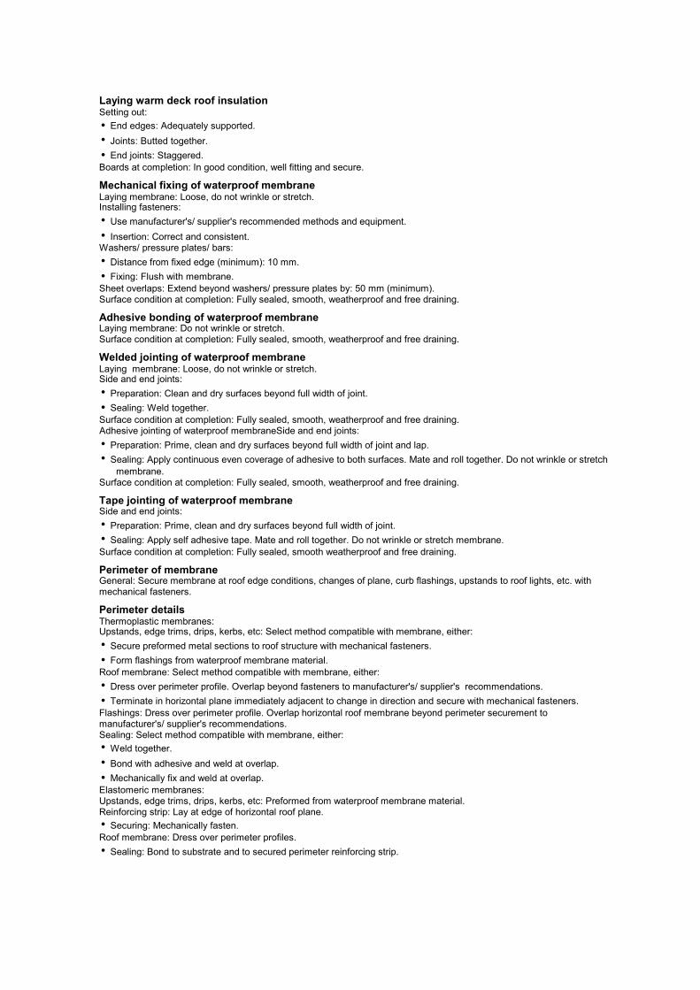
Laying warm deck roof insulationSetting out:
• End edges: Adequately supported.
• Joints: Butted together.
• End joints: Staggered.
Boards at completion: In good condition, well fitting and secure.
Mechanical fixing of waterproof membraneLaying membrane: Loose, do not wrinkle or stretch.Installing fasteners:
• Use manufacturer's/ supplier's recommended methods and equipment.
• Insertion: Correct and consistent.Washers/ pressure plates/ bars:
• Distance from fixed edge (minimum): 10 mm.
• Fixing: Flush with membrane.
Sheet overlaps: Extend beyond washers/ pressure plates by: 50 mm (minimum).Surface condition at completion: Fully sealed, smooth, weatherproof and free draining.
Adhesive bonding of waterproof membraneLaying membrane: Do not wrinkle or stretch.Surface condition at completion: Fully sealed, smooth, weatherproof and free draining.
Welded jointing of waterproof membraneLaying membrane: Loose, do not wrinkle or stretch.Side and end joints:
• Preparation: Clean and dry surfaces beyond full width of joint.
• Sealing: Weld together.
Surface condition at completion: Fully sealed, smooth, weatherproof and free draining.Adhesive jointing of waterproof membraneSide and end joints:
• Preparation: Prime, clean and dry surfaces beyond full width of joint and lap.
• Sealing: Apply continuous even coverage of adhesive to both surfaces. Mate and roll together. Do not wrinkle or stretch
membrane.Surface condition at completion: Fully sealed, smooth, weatherproof and free draining.
Tape jointing of waterproof membraneSide and end joints:
• Preparation: Prime, clean and dry surfaces beyond full width of joint.
• Sealing: Apply self adhesive tape. Mate and roll together. Do not wrinkle or stretch membrane.
Surface condition at completion: Fully sealed, smooth weatherproof and free draining.
Perimeter of membraneGeneral: Secure membrane at roof edge conditions, changes of plane, curb flashings, upstands to roof lights, etc. withmechanical fasteners.
Perimeter detailsThermoplastic membranes:Upstands, edge trims, drips, kerbs, etc: Select method compatible with membrane, either:
• Secure preformed metal sections to roof structure with mechanical fasteners.
• Form flashings from waterproof membrane material.
Roof membrane: Select method compatible with membrane, either:
• Dress over perimeter profile. Overlap beyond fasteners to manufacturer's/ supplier's recommendations.
• Terminate in horizontal plane immediately adjacent to change in direction and secure with mechanical fasteners.
Flashings: Dress over perimeter profile. Overlap horizontal roof membrane beyond perimeter securement tomanufacturer's/ supplier's recommendations.Sealing: Select method compatible with membrane, either:
• Weld together.
• Bond with adhesive and weld at overlap.
• Mechanically fix and weld at overlap.
Elastomeric membranes:Upstands, edge trims, drips, kerbs, etc: Preformed from waterproof membrane material.Reinforcing strip: Lay at edge of horizontal roof plane.
• Securing: Mechanically fasten.
Roof membrane: Dress over perimeter profiles.
• Sealing: Bond to substrate and to secured perimeter reinforcing strip.

Roof penetrationsThermoplastic membranes:Roof membrane: Cut around penetrations and secure to deck.Flanged sleeve:
• Installation: Dress over and around penetration.
• Roof membrane overlap to flange (minimum): 50 mm beyond fasteners.
• Protection to top edge of sleeve: Flashing or weathering cravat.
Elastomeric membranesRoof membrane: Cut around penetrations.Flanged sleeve:
• Installation: Dress over and around penetration.
• Seating: Flush to roof membrane.
• Roof membrane overlap to flange (minimum): 75 mm beyond fasteners.
Laying inverted roof insulationCondition of substrate: Clean.Setting out: Loose lay with staggered joints.
• Cutting: Minimize.
• Small cut pieces: Avoid at perimeters and penetrations.
• Joints: Butt together.
Projections, upstands, rainwater outlets, etc.: Cut insulation cleanly to fit closely around.Completion:
• In good condition, well fitting and stable.
• Cover to prevent wind uplift and flotation as soon as practicable.
Laying stone ballastCondition of substrate: Clean.Gravel guards: Fit to outlets.Previously laid materials: Protect whilst laying ballast.Laying: Spread evenly. Do not pile to excessive heights.
Laying precast concrete paving slabsCondition of substrate: Clean.Setting out: Minimize cutting.Joints: Open.Completion: Slabs level and stable.
InspectionInterim and final roof inspections: Submit reports.
Electronic roof integrity testTesting authority: Approved independent testing body or the roofing contractor.Timing of test: Before covering of membrane or prior to, and on completion of access by other trades.Condition of roof prior to testing:
• Waterproof membrane complete to a stage where integrity can be tested.
• Surface: Clean.
Test results and warranty: Submit on completion of testing.
CompletionRoof areas: Clean.
• Outlets: Clear.
Work necessary to provide a weathertight finish: Complete.Storage of materials on finished surface: Not permitted.Completed membrane: Do not damage. Protect from traffic and adjacent or high level working.

J44 SHEET LININGS FOR SMALL POOLS AND PONDSGENERAL
Cross-referenceGeneral: Read with A90 General technical requirements.
PRODUCTS
SandStandard: To BS EN 12620.
EXECUTION
CompetenceStandard: To BS EN 13067.
Suitability of excavated substratePreparation:
• Standing water, vegetation, topsoil and organic material, stones and debris over 50 mm: Remove.
• Contour: Gently graded without sudden changes of level or direction.
• Finish: Rolled or compacted to a smooth surface.
Penetrations: All pipes, pipe ducts, fittings, etc. complete.
Suitability of masonry substrateStructural surfaces generally: Smooth, even textured, clean and dry.Preliminary work:
• Upstands: Complete.
• Joints: Sound and flush pointed.
• Penetrations/ Outlets: Complete, sound and flush pointed.
Installation of geomembrane liningLaying: Neatly. Do not pull out all slack.
• Protection: Provide temporary protection or suspend laying operations during wet weather and high winds and if temperature of laying surface or air temperature is below 5°C.
Water inlet locations/ Penetrations: Provide double layer of geomembrane.Surface at completion: Smooth and even.
Jointing of geomembrane liningOverlaps between adjacent sheets and ends of rolls (minimum): 300 mm.Movement prior to jointing: Prevent.Bonded joints: Use materials and procedures recommended by the lining manufacturer.Wet weather, high winds or freezing conditions: Provide temporary protection or suspend jointing operations.
Installation of geosynthetic clay lining (GCL)Orientation: Lay neatly with correct side up.Damage: Prevent by using procedures recommended by the lining manufacturer.Wet or freezing conditions: Provide temporary protection or suspend laying operations.Exposed lining: Cover overnight.Penetrations: Provide double layer of membrane.Damaged areas: Repair prior to placing protective layer.Premature hydration: Give notice.Surface at completion: Smooth and even.
Jointing of geosynthetic clay lining (GCL)Overlaps between adjacent sheets (minimum): 150 mm.Overlaps at ends of rolls (minimum): 300 mm.Wet weather or freezing conditions: Provide temporary protection or suspend jointing operations.
Joint testingVisual check: Inspect all joints.Non-destructive continuity testing: Test entire length of joints.
Protective layerLaying:
• Coverage: Spread to even thickness.
• Lining: Do not damage.
Filling with waterTiming: As soon as possible after completion of joint testing. Give notice.Protective material, growing medium, plants, etc.: Do not damage or disturb.

K10 PLASTERBOARD DRY LININGS FOR WALLS, PARTITIONS AND
CEILINGSGENERAL REQUIREMENTS
Cross-referenceGeneral: Read with A90 General technical requirements.
PRODUCTS
InsulationMineral wool: To BS EN 13162.
Gypsum plasterboards to BS EN 520Type A:
• Face suitable for gypsum plasters or decoration to be applied.
Type H (plasterboard with reduced water absorption):
• Types H1, H2 and H3 have different water absorption performance.
Type E (gypsum sheathing board):
• Manufactured to be used as sheathing board in external walls.
• Not intended to receive decoration.
• Not designed to be permanently exposed to external weather conditions.
• Has reduced water absorption rates.
Type F (gypsum plasterboard with improved core adhesion at high temperatures):
• Face suitable for gypsum plasters or decoration to be applied.
Type P (gypsum baseboard):
• Face intended to receive gypsum plaster.
• May be perforated during manufacture.
Type D (gypsum plasterboard with controlled density):
• Face suitable for gypsum plasters or decoration to be applied.
Type R (gypsum plasterboard with enhanced strength):
• For applications where higher strength is required.
• Increased longitudinal and transverse breaking loads.
• Face suitable for gypsum plasters or decoration to be applied.
Type I (gypsum plasterboard with enhanced surface hardness):
• Face suitable for gypsum plasters or decoration to be applied.
• Designated Type I3.3 for edge and end profiles.
Edges:
• Normally square cut, but can be bevelled, tapered, half rounded, rounded or a combination of each.
• Type P – square or rounded.
Designation of plasterboards:
• Gypsum plasterboard/ type letter/ BS EN 520 – width/ length/ thickness/ edge profile.
• E.g. Gypsum plasterboard/ Type A/ BS EN 520 – 1200/ 2400/ 12.5/ tapered edge
Rigid beads/ stopsStandard: Galvanized steel: To BS EN ISO 1461.
EXECUTION
New wet laid basesDPCs: Install under full width of partitions/ freestanding wall linings.
Metal framing for partitions/ wall liningsSetting out: Accurately aligned and plumb.
• Frame/ Stud positions: Equal centres to suit specified linings, maintaining sequence across openings.
• Additional studs: To support vertical edges of boards.
Fixing centres at perimeters (maximum): 600 mm.Openings: Form accurately:
• Doorsets: Use sleeved/ or boxed metal studs and/ or suitable timber framing to achieve strength grade requirements for
framing assembly and adequately support weight of door.
• Services penetrations: Allow for associated fire stopping.

Additional supportsFraming: Accurately position and securely fix to give full support to:
• Partition heads: Running parallel with, but offset from main structural supports.
• Fixtures, fittings and service outlets. Mark framing positions clearly and accurately on linings.
• Board edges and lining perimeters: As recommended by board manufacturer to suit type and performance of lining.
Metal furrings for wall liningsSetting out:
• Vertical furring positions: Equal vertical centres to suit specified linings, maintaining sequence across openings.
Position adjacent to angles and openings.
• Additional vertical furrings: To support vertical edges of boards and at junctions with partitions.
• Horizontal furring positions: To provide continuous support to edges of boards.
Adhesive bedding to furrings:
• Dabs: Length 200 mm (minimum). Located at ends of furrings and thereafter at 450 mm (maximum) centres.
• Junctions with partitions: Continuous bed with no gaps across cavity.
Suspended ceiling gridsGrid members and hangers: Centres to suit specified linings and imposed loads.Additional grid members: To provide bracing and stiffening as necessary at upstands, partition heads, access hatches, etc.
Dry lining generallyGeneral: Use fixing, jointing, sealing and finishing materials, components and installation methods recommended by boardmanufacturer.Cutting plasterboard: Neatly and accurately without damaging core or tearing paper facing.
• Cut edges: Minimize and position at internal angles wherever possible. Mask with bound edges of adjacent boards atexternal corners.
Fixing boards: Fix securely and firmly to suitably prepared and accurately levelled backgrounds.Finishing: Neatly to give flush, smooth, flat surfaces free from bowing and abrupt changes of level.
Dry lining ceilingsSequence: Fix boards to ceilings before dry lining walls and partitions.Orientation of boards: Fix with bound edges at right angles to supports and with ends staggered in adjacent rows.Two layer boarding: Stagger joints between layers.
Installing mineral wool insulationFitting insulation: Closely butted joints and no gaps. Use fasteners to prevent slumping or displacement.Services:
• Electrical cables overlaid by insulation. Sized accordingly.
• Ceilings: Do not lay over luminaires.
Sealing gaps and air pathsLocation of sealant: To perimeter abutments and around openings.
• Pressurised shafts and ducts: At board-to-board and board-to-metal frame junctions.
Application: To clean, dry and dust free surfaces as a continuous bead with no gaps.
• Gaps greater than 6 mm between floor and underside of plasterboard: After sealing, fill with jointing compound.
Cavity fire barriersInstallation: Form accurately and fix securely with no gaps to provide a complete barrier to smoke and flame.Within suspended ceilings: Fixing at perimeters and joints: Secure, stable and continuous with no gaps, to provide acomplete barrier to smoke and flame.Service penetrations: Cut and pack to maintain barrier integrity. Sleeve flexible materials. Adequately support servicespassing through barriers.Ceiling systems for fire protection: Do not impair fire resisting performance of ceiling system.
Fire stopping at perimeters of dry lining systemsMaterial: Tightly packed mineral wool or intumescent mastic/ sealant.Application: Provide a complete barrier to smoke and flame.
Joints between boardsTapered edged plasterboard:
• Bound edges: Lightly butted.
• Cut/ unbound edges: 3 mm gap.
Square edged plasterboard: 3 mm gap.Square edged fibre reinforced gypsum board: 5 mm gap.
Vertical jointsJoints: Centre on studs/ framing.Partitions: Stagger joints on opposite sides of studs.Two layer boarding: Stagger joints between layers.

Horizontal jointsSurfaces exposed to view: Horizontal joints not permitted. Seek instructions where height of partition/ lining exceedsmaximum available length of board.Two layer boarding: Stagger joints between layers by at least 600 mm.Edges of boards: Support using additional framing.
• Two layer boarding: Support edges of outer layer.
Insulation backed plasterboardGeneral: Do not damage or cut away insulation to accommodate services.Installation at corners: Carefully cut back insulation or plasterboard as appropriate along edges of boards to give acontinuous plasterboard face, with no gaps in insulation.
Fixing plasterboard to metal framing:Screw fixing to framing/ furrings:
• Position of screws from edges of boards (minimum): 10 mm.
• Screw heads: Set in a depression. Do not break paper or gypsum core.
• Fixing insulation backed plasterboard to metal furrings: In addition to screw fixings, apply continuous beads of adhesivesealant to furrings.
Fixing plasterboard to timber framing:Position of nails/ screws from edges of boards (minimum):
• Bound edges: 10 mm.
• Cut/ unbound edges: 13 mm.
Position of nails/ screws from edges of timber supports (minimum): 6 mm.
Fixing plasterboard with adhesive dabsSetting out boards: Accurately aligned and plumb.Fixing to background: Securely using adhesive dabs.Dab spacing to each board horizontally: One row along top edge and one continuous dab along bottom edge.Dab spacing to each board vertically: One row along each edge and at intermediate spacings to suit size of board:
• Boards 9.5 x 1200 mm: 400 mm centres.
• Boards 9.5/ 12.5 x 900 mm: 450 mm centres.
• Boards 12.5 x 1200 mm: 600 mm centres.
Adhesive dab dimensions (width x length): At least 50–75 mm x 250 mm.
• Position of dabs from edges/ ends of boards (minimum): 25 mm.
Fixing insulation backed plasterboard with adhesive dabs: In addition to adhesive dab fixings, secure boards with nailableplugs in locations recommended by board manufacturer.
Fixing insulation backed plasterboard with adhesive spotsSetting out boards: Accurately aligned and plumb.Fixing to background: Securely using adhesive spots and mechanical fastenings.Adhesive spot spacings to each board: Four vertical rows, at 400 mm centres in each row.Adhesive spot diameters: 25 mm (minimum).Mechanical fasteners: Nailable plugs in locations recommended by board manufacturer.
Level of dry lining across jointsSudden irregularities: Not permitted.Joint deviations: Measure from faces of adjacent boards using methods and straightedges (450 mm long with feet/ pads)to BS 8212, clause 3.3.5.
• Tapered edge joints: Permissible deviation (maximum) across joints when measured with feet resting on boards: 3 mm.
• External angles: Permissible deviation for both faces, 4 mm (maximum).
• Internal angles: Permissible deviation for both faces, 5 mm (maximum).
Seamless jointing to plasterboardCut edges of boards: Remove paper burrs.Filling and taping: Fill joints, gaps and internal angles with jointing compound and cover with continuous lengths of paper tape, fully bedded.Protection of edges/ corners: Reinforce external angles, stop ends, etc. with specified edge/ angle bead.Finishing: Apply jointing compound. Feather out each application beyond previous application to give a flush, smooth,seamless surface.Nail/ screw depressions: Fill with jointing compound to give a flush surface.Minor imperfections: Remove by light sanding.
Installing beads/ stopsCutting: Neatly using mitres at return angles.Fixing: Use longest possible lengths, plumb, square and straight, ensuring full contact of wings with substrate.Finishing: After joint compounds/ plasters have been applied, remove surplus material while still wet from surfaces of beads exposed to view.

Repairs to existing plasterboardFilling small areas with broken cores: Cut away paper facing, remove loose core material and fill with jointing compound.
• Finish: Flush, smooth surface suitable for redecoration.
Large patch repairs: Cut out damaged area and form neat hole with rectangular sides. Replace with matchingplasterboard.
• Fixing: Use methods to suit type of dry lining, ensuring full support to all edges of existing and new plasterboard.
• Finishing: Fill joints, tape and apply jointing compound to give a flush, smooth surface suitable for redecoration.

K11 RIGID SHEET FLOORING, SHEATHING, DECKING, SARKING, LININGS
AND CASINGSGENERAL
Cross-referenceGeneral: Read with A90 General technical requirements.
PRODUCTS
AdhesivesBonding and jointing adhesives generally: PVA to BS EN 204, class D3.Bonding and jointing adhesives to fire resistant flooring or flooring exposed to regular wetting: Phenol-resorcinolformaldehyde to BS EN 301, type I.
Battens for floating floorsTimber: Regularized softwood.Timber quality: Free from decay, insect attack (except ambrosia beetle damage).
• Knot width (maximum): Half section width.
Moisture content at time of laying: 16% (maximum).
InsulationExpanded polystyrene insulation (EPS): To BS EN 13163.Extruded polystyrene insulation (XPS): To BS EN 13164.Mineral wool insulation (MW): To BS EN 13162.Polyurethane insulation (PUR): To BS EN 13165.
Rigid sheet materialsPlywood: To BS EN 636.
• Bonding quality to BS EN 314-2.
• Appearance class to BS EN 635.
Particleboard: To BS EN 312.
• General purpose - Dry: Type P1.
• Interior fitments - Dry: Type P2.
• Loadbearing - Dry: Type P4.
• Loadbearing - Humid: Type P5.
• Heavy duty loadbearing - Dry: Type P6.
• Heavy duty loadbearing - Humid: Type P7.
Cement bonded particleboard: To BS EN 634-2.Oriented strand board (OSB): To BS EN 300.
• General purpose boards, and boards for interior fitments for use in dry conditions: Type OSB/1.
• Loadbearing boards for use in dry conditions: Type OSB/2.
• Loadbearing boards for use in humid conditions: Type OSB/3.
• Heavy duty loadbearing boards for use in humid conditions: Type OSB/4.
Hardboard: To BS EN 622-2.Medium density fibreboard: To BS EN 622-5.Plasterboard: To BS EN 520.Technical class: To BS EN 13986, depending on purpose and conditions of use.Strength and stiffness (minimum): To BS EN 1995-1-1.

EXECUTION
Ribbed (battened) floating floorsPugging or additional insulating material: Lay between joists.Installation:
• Setting out of floating substrate (where specified): Long edges running across battens. End joints central over battens
and staggered.
• Setting out of flooring: Long edges running across battens. End joints central over battens and staggered. All joints
glued.
• Flooring laid over floating substrate: Joints must not coincide.Expansion provision:
• Expansion gap around perimeter of floor area and upstands: 10–12 mm filled with resilient material.
Location of mechanical fixings to battens:25 mm from long edges of boards/ sheets and 10 mm (minimum) from shortedges.Plywood fixing centres:
• Around floor perimeter and along short edges of each board: 150 mm (maximum).
• Along intermediate supports: 300 mm (maximum).
Particleboard fixing centres:
• Around floor perimeter and along short edges of each board: 200 mm (maximum).
• Along intermediate supports: 400 mm (maximum).
Oriented strand board (OSB) fixing centres:Around floor perimeter, along short edges of each board, and along intermediate supports: 300 mm (maximum).Cement bonded particleboard fixing centres:
• Around floor perimeter, along short edges of each board, and along intermediate supports: Recommended by sheet
manufacturer.
• Fixings distance from long edges and minimum from short edges: Recommended by sheet manufacturer.
Platform (continuously supported) floating floorsPugging or additional acoustic insulating material: Lay between joists.Vapour control layer: Lay on warm side of insulation.Installation:
• Floating substrate (where specified): Laid on resilient layer with close butted joints.
• Flooring: End joints staggered. Joints in flooring and floating substrate must not coincide.Expansion provision:
• Clear expansion gap around perimeter of floor area and upstands: 10–12 mm.
FlooringSubstrate: Provide necessary additional supports.Setting out: Long edges running across joists. End joints central over joists and staggered.Expansion provision:
• Clear expansion gap around perimeter of floor area and upstands: 10–12 mm.
• Intermediate expansion/ movement joints between boards/ sheets: As recommended by manufacturer.
Location of fixings: 25 mm from long edges of board/ sheet and 10 mm (minimum) from short edges.Plywood fixing centres:
• Around floor perimeter and along short edges of each board: 150 mm (maximum).
• Along intermediate supports: 300 mm (maximum).Particleboard fixing centres:
• Around floor perimeter: 200 mm (maximum).
• Along intermediate supports: 400 mm (maximum).Oriented strand board fixing centres:
• Around floor perimeter, along short edges of each board, and along intermediate supports: 300 mm (maximum).
Cement bonded particleboard fixing centres:
• Around floor perimeter, along short edges of each board, and along intermediate supports: Recommended by sheet
manufacturer.
• Fixings distance from long edges and minimum from short edges: Recommended by sheet manufacturer.
Wall sheathingSubstrate: Provide necessary additional supports.Long edges: Vertical. Centre on supports.Expansion gap between adjacent boards: 2–3 mm.Fixing centres:
• Around board edges: To BS EN 1995-1-1.
• Along intermediate supports: 300 mm (maximum).
Fixing distance from edges: 25 mm from bottom edge of board and 10 mm (minimum) from other edges.

Rigid sheet insulation fixed through wall sheathingSetting out: Tongue uppermost, with no gaps.Fixing centres: Around board edges and along intermediate supports: Recommended by sheet manufacturer.
Roof deckingSubstrate: Provide necessary additional supports.Setting out: Long edges running across supports. End joints central over joists and staggered.Expansion provision:Clear expansion gap around perimeter of roof area and upstands:
• Plywood: 10 mm.
• Particleboard/ OSB: 1.5 mm per metre run of roof, with a gap of 10 mm (minimum).
Intermediate expansion/ movement joints: Recommended by decking manufacturer.
SarkingSubstrate: Provide necessary additional supports.Setting out: Long edges running across rafters. End joints central over joists and staggered.Plywood fixing centres to each rafter:
• Around roof perimeter and along short edges of each board: 150 mm (maximum).
• Along intermediate supports: 300 mm (maximum).
• Distance from edges: 25 mm from long edges and 10 mm (minimum) from short edges.
Particleboard fixing centres (maximum) to each rafter:
• Around roof perimeter, along short edges of each board, and along intermediate supports: 100 mm.
• Distance from edges: 25 mm from long edges and 10 mm (minimum) from short edges.
Oriented strand board fixing centres to each rafter:
• Around roof perimeter and along short edges of each board: 150 mm (maximum).
• Along intermediate supports: 300 mm (maximum).
• Distance from edges: 25 mm from long edges and 8 mm (minimum) from short edges.
Rigid board insulation fixed as roof sarkingRigid board insulation:
• Installation: Neatly. Leave no gaps. Secure with counterbattens.
• Fixing: Fix counterbattens along line of each rafter. Secure through insulation to rafters with fasteners at 300 mm
centres.Additional insulation between counterbattens:
• Installation: Tight between counterbattens. Close butt joints.
• Top of insulation: 12 mm (minimum) below top of counterbattens.
UnderlaySubstrate:
• Condition: Sound and acceptably level.
• Preparation: Gross irregularities removed or filled.
• Protruding fasteners: Remove or punch in.
Setting out:End joints: Stagger.
• Joints in underlayment: Offset from joints in substrate.Fixing:
• Fixing centres: 150 mm grid over each sheet commencing at centre.
• Centres around perimeter: 100 mm (maximum).
• Distance from edges: 12 mm.
• Fastener heads: Set flush with sheet surface.Plywood:
• Gap between adjacent sheets: 0.5–1 mm.
Hardboard:
• Laying: Smooth side uppermost.
• Gap between adjacent sheets: 1–2 mm.

Wall linings, ceilings and casingsSubstrate: Provide necessary additional supports.Setting out lining: Run long edges across supports. Lay with a gap between adjacent boards.Fixing lining to supports:Plywood fixing centres:
• Around board edges: 150 mm (maximum).
• Along intermediate supports: 300 mm (maximum).
• Distance from edges: 10 mm (minimum).
Particleboard fixing centres:
• Around board edges and along intermediate supports: 200 mm (maximum).
• Distance from board edges: 9 mm (minimum).
Cement bonded particleboard fixing centres:
• Around board edges, along intermediate supports and distance from edges: Recommended by sheet manufacturer.
Centres along supports: Recommended by sheet manufacturer.
• Distance from long edges: 50 mm (minimum).
Hardboard fixing centres:
• Around sheet edges, along intermediate supports and distance from edges: Recommended by sheet manufacturer.
Medium density fibreboard fixing centres:
• Around board edges and along intermediate supports: Recommended by sheet manufacturer.
• Distance from edges: 12 mm (minimum).
Installation generallyTiming: Building to be weathertight before fixing boards internally.Moisture content of timber supports: 18% (maximum).Joints between boards: Accurately aligned, of constant width and parallel to perimeter edges.Methods of fixing, and fasteners: As section Z20 unless specified otherwise.
Dryness of concrete/ screed substrates for floating floorsRelative humidity above substrate when tested with a hygrometer to BS 8201, Appendix A: 75% (maximum).
• Test points: All corners, around perimeter, and random points over area being tested.
• Drying aids: Turned off for 4 days (minimum) before testing.
Vapour control layer in floating floor constructionLocation: Immediately below floating layer.Installation:
• Joints: Overlapped by 150 mm (minimum) and sealed with vapour resistant tape.
• Treatment of membrane at perimeter of flooring and upstands: Turned up and sealed to top face of flooring using a
method approved by the board manufacturer.
• Excess material: Trimmed off neatly after fixing skirtings/ cover beads.
• Condition of membrane before laying flooring: Clean and dry.
Plain softwood battens for floating floorsQuality of timber: Free from decay, insect attack (except ambrosia beetle damage) and with no knots.wider than half the width of the section.Moisture content at time of laying: 16% (maximum).
Additional supportsAdditional studs, noggings/ dwangs (Scot) and battens:
• Provision: In accordance with board manufacturer's recommendations and as follows:
Tongue and groove jointed rigid board areas: To all unsupported perimeter edges.Butt jointed rigid board areas: To all unsupported edges.
• Size: 50 mm (minimum) wide and of adequate thickness.
• Quality of timber: As for adjacent timber supports.
• Treatment (where required): As for adjacent timber supports.
Board moisture content and conditioningMoisture content of boards at time of fixing: Appropriate to end use.Conditioning regime: Submit proposals.
Fixing generallyBoards/ sheets: Fixed securely to each support without distortion and true to line and level.Fasteners: Evenly spaced in straight lines and, unless otherwise recommended by board manufacturer, in pairs acrossjoints.
• Distance from edge of board/ sheet: Sufficient to prevent damage.
Surplus adhesive: Removed as work proceeds.

Open jointsPerimeter joints, expansion joints and joints between sheets: Free from plaster, mortar droppings and other debris.Temporary wedges and packings: Removed on completion of board fixing.
Access panelsSize and position: Agree before boards are fixed.Additional noggings/ dwangs (Scot), battens, etc: Provide and fix as necessary.

K20 TIMBER BOARD FLOORING DECKING SARKING LININGS AND
CASINGSGENERAL
Cross-referenceGeneral: Read with A90 General technical requirements.
PRODUCTS
Timber board flooringBasic quality tongued and grooved softwood: To BS 1297.
Timber board sarkingBasic quality: Softwood, free from decay, insect attack (except ambrosia beetle damage) and wane.Boards with soffit exposed as finish: Blue stain, fissures, knot holes and loose or unsound knots not permitted on exposed(underside) face of boards.Treatment:
• Preservative impregnation: To Wood Protection Association Commodity Specification C4 or C8.
• Fire retardant impregnation: To Wood Protection Association Commodity Specification FR4.
Moisture content at time of fixing: Not more than 19%.
Timber board linings, casings, etc.Standard: To BS 1186-3.
Battens for floating floorsQuality: Free from decay, insect attack (except ambrosia beetle damage) and with no knots wider than half the width of thesection.Treatment:
• Preservative impregnation: To Wood Protection Association Commodity Specification C8.
EXECUTION
GenerallyProtection during and after installation: Keep boards dry. Protect from dirt, stain and damage until Completion.
Boards to be used internally:Do not install until building is watertight.
Moisture content of concrete/ screed substrates for wood floating floorsTest for moisture content:
• Standard: To BS 8201, Appendix A, using an accurately calibrated hygrometer.
• Readings: Take in corners, along edges, and at random points over the area being tested.
Acceptability:Do not lay flooring until all readings show 75% relative humidity or less.
Moisture content of timberGeneral:
• Conditions during and after installation: Control ambient temperature and humidity conditions to maintain moisture
content at average level specified in BS EN 942, table B.1 for the relevant service condition until Completion.
• Test for moisture content: When instructed, using an approved moisture meter.
Sarking:
• Moisture content at time of fixing (maximum): 19%.Timber supports:
• Moisture content at time of fixing boards (maximum): 18%.
Battens for floating floors:
• Moisture content at time of fixing boards (maximum): 16%.
Timber board linings, casings, etc.Board fixing: To BS 1186-3.Access panels:
• Size and position: Agree before fixing boards.
• Additional noggings/ dwangs, battens, etc: Provide as necessary.

Installing vapour check membrane to floating floorsLocation: Immediately below the floating layer.Joints: Overlap by at least 150 mm and seal with vapour resistant tape.Perimeter/ Upstands: Turn membrane up around perimeter of flooring and around any upstands and seal to top face of boards.
• Excess material: Trim off neatly after fixing skirtings/ cover beads.Membrane condition: Intact, clean and dry prior to laying flooring.
Treated timberSurfaces exposed by minor cutting and/ or drilling: Treat with two flood coats of a solution recommended by maintreatment solution manufacturer.
Fixing boardsEnvironmental conditions: Do not fix boards when ambient temperature is at or below 0°C, or above 30°C.General: Fix boards securely to each support to give flat, true surfaces free from undulations, lipping, splits and protrudingfastenings.Timber movement: Position boards and fixings to prevent cupping, springing, excessive opening of joints and other defects.Heading joints: Tightly butted, central over supports and at least two board widths apart on any one support.Termination of sarking at roof edges and junctions: In accordance with drawings and specification for roof covering.Exposed nail heads: Neatly punch below surface.Proud edges: Plane off.

K21 WOOD STRIP OR BOARD FINE FLOORING OR LININGSGENERAL
Cross-referenceGeneral: Read with A90 General technical requirements.
PRODUCTS
Wood boards/ stripsQuality: Free from decay, through splits and insect attack (including ambrosia beetle damage, unless permitted in theappearance class/ grade specified).Finish: Planed all round.
EXECUTION
Workmanship generallyMoisture content of timber supports: 12-14%.Methods of fixing and fasteners: As section Z20 where not specified.Protection: Protect from dirt, stains and damage using suitable coverings and boards laid as the work proceeds.
Environmental conditionsGeneral requirements prior to starting work specified in this section: Building weathertight, wet trades completed andaffected areas dried out.Temperature and humidity before, during and after installing strips/ boards: Maintained at levels approximating to thosewhich will prevail after building is occupied.
Dryness of concrete/ screed substrates for flooringRelative humidity above substrate when tested with a hygrometer to BS 8201, Appendix A (maximum): 75%.
• Test points: All corners, around perimeter, and random points over area being tested.
Drying aids: Turned off for not less than four days before testing.
Vapour control layer installationLocation: Immediately below boards/ strips.Joints: Overlapped by minimum 150 mm and sealed with vapour resistant tape.Treatment of membrane at perimeter of flooring and upstands:
• Turned up and sealed to top face of flooring using a method approved by the strip/ board manufacturer.
• Excess material: Trimmed off neatly after fixing skirtings/ cover beads.Condition of membrane before laying flooring: Clean and dry.
Treated timberSurfaces exposed by minor cutting and drilling: Treated with two flood coats of a solution recommended for the purpose bymain treatment solution manufacturer.
Access panelsSize and position: Agree before strips/ boards are fixed.Additional noggings/ dwangs (Scot), battens, etc: Provide and fix as necessary.
Fixing strips/ boardsStrips/ Boards: Fixed securely to each support with flat, true surfaces free from undulations, splits, hammer marks,scratches and protruding fastenings.Movement of timber: Allowed for when positioning strips/ boards and fastenings to prevent cupping, springing, opening of joints or other defects.Heading joints (where permitted): End matched, butted and, where applicable, positioned centrally over supports anddistributed across the flooring to achieve a random effect.
Expansion provisionExpansion gaps:
• Edges of flooring: Parallel to lie of strips/ boards and 10 mm wide unless otherwise recommended by flooring
manufacturer/ supplier.
• Ends of flooring: 10 mm wide.
Spacer blocks and debris: Removed before fixing skirtings/ cover fillets.Intermediate expansion/ movement joints: Formed as recommended by flooring manufacturer/ supplier.
Finish to flooring and liningExposed fastener heads: Punched or set below surface and filled with stopping to match wood.Strips/ Boards: Sanded to give a clean, smooth and flush surface free from score marks.

K30 PANEL PARTITIONSGENERAL
Cross-referenceGeneral: Read with A90 General technical requirements.
PRODUCTS
Relocatable partition systemsStrength grading: To BS 5234.Fire resistance testing generally: To BS 476-22.
• Load bearing partition/ ceiling systems: To BS 476-21.Sound performance: In accordance with BS EN ISO 140 and BS EN ISO 717-1.
Glass for relocatable partitionsStandard: To BS 952 and relevant parts of:
• BS EN 572 for basic soda lime silicate glass.
• BS EN 1096 for coated glass.
• BS EN 1748 for special glass.
• BS EN ISO 12543 for laminated glass.
Impact performance: To BS 6206.
PlasterboardStandard: To BS 1230-1.Fire resistance testing generally: To BS 476-22.Exposed surfaces and edge profiles: Suitable to receive specified finish.
Insulation to partition coreMineral wool: To BS EN 13162.
Softwood sole plates and framing inserts to plasterboard panel partitionsTimber: Sawn softwood.Timber quality: Free from decay, insect attack (except ambrosia beetle damage).
• Knot width (maximum): Half section width.
Moisture content at time of laying: 16% (maximum).Fixing sole plates:
• To concrete: Plugged and screwed.
• To timber: Screwed through to joists.
EXECUTION
Environmental conditionsGeneral: Before, during and after installation, maintain temperature and humidity levels similar to those that will prevailafter building is occupied.
New wet laid basesDpcs: Install under full width of partitions.Perimeter joints: Sealed to provide an impervious structure.Skirtings: Sealed to partitions and floors.
Installation generallySetting out: Plumb, true to line and level. Free from bowing, undulations and other planar distortions.Joints: Align accurately with no lipping.Additional supports: Provide where necessary at perimeters to ensure stability.Moisture and thermal movement: Make adequate allowance.
Installing relocatable partitionsPerimeter abutments: Accommodate deviations whilst maintaining partition system performance. Form make up/ closer pieces accurately around projections and features.Customization: Do not cut or otherwise alter framing/ panels on site, except where shown on drawings.Intermediate joints in exposed frame members and trims: Keep to a minimum.
Installing plasterboard panel partitionsTimber or metal framing inserts: Size to give a firm press fit into the panel cavity.Perimeter fixing:
• Preparation: Fix continuous sole plate to floor at 600 mm centres.
• Floor, wall and ceiling: Fix framing inserts to substrates at 600 mm centres. Locate panels into framing inserts and fix at300 mm centres with screws or 230 mm centres with nails.

Installing plasterboard laminated partitionsJoints: Stagger between layers by 150 mm (minimum).Layers: Fully bond with bands of adhesive. First and third layers nailed to battens.Fire resisting partitions: Provide additional mechanical fixings in accordance with partition manufacturer'srecommendations.Complete partitions: Protect against movement for four hours (minimum).
Taped seamless finish to plasterboard partitionsCut edges of boards: Lightly sand to remove paper burrs.Joints, gaps and internal angles: Fill with jointing compound and cover with continuous lengths of paper tape, fully bedded.Finish flush with board surface.Edges and corners: Reinforce with edge/ angle bead or tape.Nail/ screw depressions: Fill with jointing compound to give a flush surface.Minor imperfections: Remove by lightly sanding.
Perimeter sealsApplication: To clean, dry, dust-free surfaces, with no gaps in accordance with sealant manufacturer's instructions.
Fire stoppingGaps at junctions of partitions with perimeter abutments, cavity barriers, service penetrations, and the like: Seal tightly toprevent penetration of smoke and flame.Material: Non-combustible or intumescent.
Glazing for relocatable partitionsPanel size: ±2 mm of nominal size.Pane condition: Clean and free from obvious scratches, bubbles, rippling, dimples and other defects.Preglazed panels: Capable of being reglazed in situ.
Ironmongery for relocatable partitionsInstallation: Accurate and without damage to components or surrounding surfaces.Completion: Check, adjust and lubricate as necessary for correct operation.
K32 PANEL CUBICLES LININGS AND SCREENSGENERAL
Cross-referenceGeneral: Read with A90 General technical requirements.
PRODUCTS
High pressure laminate (HPL)Laminate facings < 2 mm thick, single faced, bonded to substrate: To BS EN 438-3.Compact laminate > 2 mm thick, double faced: To BS EN 438-4.
Particleboard, moisture resistingStandard: To BS EN 312, Type P5.
EXECUTION
ProtectionDoors and panels: Stack flat on bearers and separate by spacers where necessary to prevent damage to or fromprojections.Completed cubicles: Keep clean and dry, and adequately protect from damage until completion.
InstallationProgramming: Do not install cubicles or duct/ wall panels before building is weathertight, wet trades have finished their work, wall and floor finishes are complete, and the building is well dried out.Accuracy: Set out to ensure frames and/ or panels and doors are plumb, level and accurately aligned.Modifications: Do not cut, plane or sand prefinished components except where shown on drawings.Fixing: Secure components using methods and fasteners recommended by the cubicle/ panel manufacturer. Preventpulling away, bowing or other distortions to frames, panels and doors.Moisture and thermal movement: Make adequate allowance for future movement.

K40 DEMOUNTABLE SUSPENDED CEILINGSGENERAL
Cross-referenceGeneral: Read with A90 General technical requirements.
PRODUCTS
Suspended ceiling componentsStandard: To BS EN 13964.
• Aluminium sheet, strip and plate: To BS EN 485.
• Aluminium bars, tubes and sections: To BS EN 573, BS EN 755, and BS EN 12020.
Softwood edge battensStandard: To BS EN 942.
• Moisture content at time of fixing: 15% ± 2%.
EXECUTION
Setting outGeneral:A continuous and even surface, jointed (where applicable) at regular intervals. Infill and access units, integrated services: Fitted correctly and aligned.Edge/ Perimeter infill units size (minimum): Half standard width or length.Corner infill units size (minimum): Half standard width and length.Grid: Position to suit infill unit sizes. Allow for permitted deviations from nominal sizes of infill units.Infill joints and exposed suspension members: Straight, aligned and parallel to walls, unless specified otherwise.Suitability of construction: Give notice where building elements and features to which the ceiling systems relate are notsquare, straight or level.
ProtectionLoading: Do not apply loads for which the suspension system is not designed.Ceiling materials: When necessary, remove and replace correctly using special tools and clean gloves, etc. asappropriate.
Installing hangersWire hangers: Straighten and tension before use.Installation: Install vertical or near vertical without bends or kinks. Do not allow hangers to press against fittings, services,or insulation covering ducts/ pipes.Obstructions: Where obstructions prevent vertical installation, either:
• Brace diagonal hangers against lateral movement; or
• Hang ceiling system on an appropriate rigid sub-grid bridging across obstructions and supported to prevent lateral
movement.Extra hangers: Provide as necessary to carry additional loads.Fixing:
• Wire hangers: Tie securely at top with tight bends to loops to prevent vertical movement.
• Angle/ Strap hangers: Do not use rivets for top fixing.
Installing perimeter trimsJointing: Neat and accurate, without lipping or twisting.
• External and internal corners: Mitre joints.
• Intermediate butt joints: Minimize. Use longest available lengths of trim. Align adjacent lengths.
Fixing: Fix firmly to perimeter wall, edge battens or other building structure.
Exposed gridsMain runners: Install level. Adjust with supporting hangers taut. Do not kink or bend hangers.
• Spliced joints: Stagger.
• Wire hangers passing through main runners: Sharply bend and tightly wrapped loops.
• Angle/ Strap hangers: Do not use rivets for bottom fixing.
• Angular displacement of long axis of one runner in relation to next runner in line with it: Not visually apparent.
Cross members supported by main runners or other cross members: Install perpendicular to intersecting runners.Cross tees: Flat and coplanar with flanges of main runners after panel insertion:
• Cross tees over 600 mm long, cut and resting on perimeter trim: Provide an additional hanger.Holding down clips: Locate to manufacturer's recommendations.
• Fire protecting/ resisting ceiling systems: Use clip type featured in the fire test/ assessment.

Concealed gridsPrimary support channels: Install level. Do not kink or bend hangers.
• Wire hangers wrapped around primary channels: Twice wrapped. Loops tightly formed.
• Angle/ Strap hangers: Do not use rivets for bottom fixing.
Splines: Locate between infill units to assist levelling of adjacent units and to resist air movement at joints.Spring-tee grids: Do not omit primary channel.
Installing mineral infill unitsGeneral:
• Perimeter infill units: Trimmed, as necessary, to fully fill space between last grid member and perimeter trim. Prevent
subsequent movement.
• Deeply textured infill units: Minimize variations in apparent texture and colour. In particular, avoid patchiness.
Concealed grids: Install infill units uniformly, straight and aligned. Avoid dimension creep.
• Infill units around recessed luminaries and similar openings: Prevent movement and displacement.
Installing metal infill unitsSound absorbing pads: Fit to prevent upward air movement through infill units. Cut or fold pads in cut perimeter infill unitsto full unit size. Reseal cut pads.Perimeter infill units: Firmly wedge cut units into perimeter trim, or clip down.
Openings in ceiling materialsGeneral: Neat and accurate. To suit sizes and edge details of fittings. Do not distort ceiling system.
Integrated servicesGeneral: Position services accurately, support adequately. Align and level in relation to the ceiling and suspension system.Do not diminish performance of ceiling system.Small fittings: Support with rigid backing boards or other suitable means. Do not damage or distort the ceiling.
• Surface spread of flame rating of additional supporting material: Not less than ceiling material.
Services outlets:
• Supported by ceiling system: Provide additional hangers.
• Independently supported: Provide flanges to support ceiling system.
Ceiling mounted luminairesSupport:
• Independently supported luminaires: Suspension adjusted to line and level of ceiling.
• Ceiling supported luminaires: Do not inhibit designed grid expansion in fire.
Modular fluorescent recessed luminaires: Compatible with ceiling module. Extension boxes must not foul ceiling system.Recessed rows of luminaires: Provide flanges for support of grid and infill units, unless mounted above grid flanges.Retain in position with lateral restraint.Fire protecting/ resisting ceiling systems: Luminaires must not diminish protection integrity of ceiling system.Access: Provide access for maintenance of luminaires.
Mechanical servicesFan coil units:
• Inlet and outlet grilles: Trim ceiling grid and infill units to suit.
• Space beneath: Sufficient for ceiling system components.
• Suspension and connections: Permit accurate setting out and levelling of fan coil units.
Air grilles and diffusers:
• Setting out: Accurate and level.
• Linear air diffusers: Retain in place with lateral restraint. Provide flanges for support of grid and infill units.
• Grille/ Diffuser ceiling joints: Provide smudge rings and edge seals.
Smoke detectors and PA speakers:
• Ceiling infill units: Scribe and trim to suit.
• Flexible connections: Required.Sprinkler heads: Carefully set out and level.
Installing insulationFitting: Fit accurately and firmly with butted joints and no gaps.Insulation within individual infill units: Fit closely. Secure to prevent displacement when infill units are installed or subsequently lifted.
• Dustproof sleeving: Reseal, if cut.
Width: Lay insulation in the widest practical widths to suit grid member spacings.Services: Do not cover electrical cables that have not been sized accordingly. Cut insulation carefully around electricalfittings, etc. Do not lay insulation over luminaires.Sloping and vertical areas of ceiling system: Fasten insulation to prevent displacement.

Ceiling systems intended for fire protectionJunctions of ceiling systems with perimeter abutments and service penetrations: Seal gaps with tightly packed mineralwool or intumescent sealant to prevent penetration of smoke and flame.Ceiling system/ Wall junctions: Maintain protective value of ceiling system.
• Fixings and grounds: Noncombustible.
• Metal trim: Provide for thermal expansion.
Access and access panels: Maintain continuity of fire protection.
Installing cavity fire barriersFixing:
• General: Fix barriers securely to channels or angles at abutments to building structure.
• At perimeters and joints: Provide permanent stability and continuity with no gaps to form a complete barrier to smoke
and flame.Joints: Form to preserve integrity in fire.Service penetrations: Cut barriers neatly to accommodate services. Fit fire resistant sleeves around flexible materials. Fillgaps around services to fire barrier manufacturer's recommendations to maintain barrier integrity. Adequately supportservices passing through the barrier.Ceiling systems intended for fire protection: Do not impair fire resisting performance of ceiling system.Ceiling systems not intended for fire protection: Do not mechanically interlink barriers with ceiling system.
Installing sound barriersSetting out: Align accurately with partition heads.Fixing: Fix tightly at perimeters and joints using methods recommended by barrier manufacturer, including steel supportsections as appropriate. Provide permanent stability and continuity Completed installation to be stable, secure andcontinuous, with no gaps.Gaps at junctions with partition heads, ceiling system, structural soffit, walls, ducts, pipes, etc.: Seal with mineral wool or suitable sealant.
Electrical continuity and earth bondingSubstantial conductive parts of the ceiling system: Electrically continuous and fully earth bonded to carry prospective earthfault currents.
• Standard: To BS 7671.
Sequence: Complete earth bonding as soon as possible after completion of each independent area of suspension system.Testing: After completion of the ceiling system, associated services and fittings, test conductive parts of suspensionsystem required to carry earth fault current, or used as bonding connections. Give notice before testing.
• Electrical continuity: Measure from various distant conductive points of ceiling system and to earth bar in distribution
board serving the area.
• Test current: Sufficient to indicate probable electrical performance under fault conditions.
• Test instrument: Type providing a pulse of about 25 A at safe voltage for safe duration, and indicating resistance in
ranges 0-2 ohms and 0-20 ohms.
• Resistance of measuring conductors: Deduce from test instrument readings.
• Test readings: Record and certify. Add results to resistance of other parts of the path forming the earth fault loop.

K41 RAISED ACCESS FLOORSGENERAL
Cross-referenceGeneral: Read with A90 General technical requirements.
PRODUCTS
Raised access flooring systemStandards: To BS EN 12825 or MOB PF2 PS/SPU. References to Authority in MOB PF2 PS/SPU are deemed to be toEmployer.
Cavity barriersStandard: Fire resistance tested to BS 476-20.
EXECUTION
Preparation:Subfloor: Clean before installation and keep clean during installation.Setting out: Before installation of services, indelibly mark pedestal positions.Fixtures: Before installation, complete the fixtures which floor panels are to be cut around or which supports are to bridge.
Environmental conditionsGeneral:
• Dry, well ventilated, not subject to extremes of temperature or humidity, and free from rapid variations of temperature or humidity.
• RH of air (maximum): 75%.
• RH of surrounding walls (maximum): 75%.Subfloors:
• RH (maximum): 75% tested to BS 8201 using an accurately calibrated hygrometer.
• Temperature (minimum): 5°C.
DustproofingSealing: Surfaces to be sealed must be clean, dry and free from dust, grease and other contaminants.Application: First coat: Apply before pedestals are erected. Second coat: Different tint to first coat, apply after completion of services and other associated work.
Cut floor panelsSize (minimum): Half full width x half full length.Burrs and rough edges: Make smooth.Edge sealing: Seal exposed cut edges of floor panels that have moisture sensitive or combustible cores.
PerimetersExpansion gaps: 10 mm at abutments.Filling: Before fixing skirtings and cover strips.
Cavity barriersPerformance: Permanently stable, continuous, and an effective barrier to smoke and flame.Fixing: Fix securely to subfloor, at joints and as necessary.Floor panels: Firmly secure floor panels above cavity barriers.Gaps between cavity barriers and other elements: Seal with mineral wool or other suitable material.Fire stopping: Give notice when fire stopping is complete.
Level changesRamps and steps:
• Performance: Match performance of associated raised access floor.
• Proposals: Submit details.
Under-floor plenum air barriersMaterial: Rigid or semirigid nonporous sheets with smooth nondusting surfaces.Performance: Permanently stable, continuous and airtight.Fixing: Fix securely to subfloor, at joints and as necessary.Edges and joints: Seal.

Electrical continuity and earth bondingSubstantial metal parts of raised access floor: Electrically continuous and fully earth bonded.
• Standard: To BS 7671.
• Bonding and earthing methods: Submit proposals.
Earth bonding connection points: Determine number and location. Provide connectors.Total resistance of earth fault loop (maximum): Resistance required to operate earth fault protection devices to BS 7671.Electrical continuity and earth bonding tests:
• General: Test complete raised access floor.
• Points for testing: Randomly selected pedestals, stringers, tops and bottoms of floor panels.
Integral finishes electrical resistance testsGeneral: Test complete raised access floor.Testing agent: Qualified electrician.
CompletionInstallation: Clean and stable. Free from bounce and vibration. No lipping between floor panels. Floor panel labelling:
• Nonstandard panels: Identify for relocation purposes.
• Service identification labels: Provide self-adhesive labels to identify under-floor services and their direction. Fix to the
visible surface of the floor panel, and under carpet finish if any.
User instructionsManual contents: Include the following:
• Correct method for lifting and replacing floor panels and stringers.
• Servicing: Limitations on sequence, number and positions of floor panels and stringers that can be removed safely at
one time.
• Permissible loads: With guidance on use of spreader plates when shifting heavy equipment and subsequentmaintenance.
• Methods for installing cabling and ducts, to prevent damage to supporting structure.
• Cleaning methods: For floor panels and integral finishes.
• Floor panel covering renewal: Method for replacement of integral floor panel coverings.
• Pedestal adjustment and locking.
• Maintenance: Recommended methods and frequency. Minimum maintenance-free life of raised access floor system.
Minimum maintenance-free life of replaceable parts where this differs from that of the whole system. Minimum periodduring which replaceable components will be available.
• Installation instructions, including COSHH Assessment.
CleaningSubfloors: After completion, thoroughly clean accessible areas of subfloors and leave free of dust and debris.Raised access floor: Before delivery of items carried by floor, clean thoroughly.

L10 WINDOWS ROOFLIGHTS SCREENS AND LOUVRESGENERAL
Cross-referenceGeneral: Read with A90 General technical requirements.Sealants: Read with section Z22 Sealants.Joinery workmanship: Read with section Z10 Purpose made joinery.
PRODUCTS
Moisture content of windows, screens, louvres and subframes on delivery to siteExternal joinery: 12–19%.For unheated buildings: 12–16%.For buildings with heating providing room temperatures in the range 12–21°C: 9–13%.For buildings with heating providing room temperatures in excess of 21°C: 6–10%.
WindowsAluminium:
• Standard: To BS 4873.
• Factory applied powder coatings: To BS 6496.
PVC-U windows (white and surface covered):
• Standard: Manufactured to BS 7412 from extruded profiles.
• Manufacturer: Registered under a quality assurance scheme operated by a certification and inspection body accreditedby the United Kingdom Accreditation Service (UKAS).
• Operation and strength characteristics: To BS 6375-2.
Steel:
• Standard: To BS 6510.
• Operation and strength characteristics: To BS 6375-2.
• Factory applied powder coatings: To BS EN 13438.
Wood:
• Standard: To BS 644.
• Manufacturer: Registered under a third party quality assurance scheme.
• Operation and strength characteristics: To BS 6375-2.
Wood members for purpose made windows, screens, louvres and subframesTimber: Generally to BS EN 942.Appearance class to BS EN 942:
• For opaque finish: Glazing beads, drip mouldings and the like, class J10; all other members, J40 or better.
• For clear finish: Glazing beads, drip mouldings and the like, Class J2; other members, as specified.
Knots on arrises and finger jointing in timber: Not permitted where exposed to view.Adhesives:
• Polyvinyl acetate (PVAC) to BS EN 204, class D4.
• Thermosetting resin to BS EN 12765, class C4.
EXECUTION
Protection of componentsGeneral: Do not deliver to site components that cannot be installed immediately or placed in clean, dry floored andcovered storage.Stored components: Stack vertical or near vertical on level bearers, separated with spacers to prevent damage by and toprojecting ironmongery, beads, etc.
Priming/ sealingWood surfaces inaccessible after installation: Prime or seal before fixing components.
Corrosion protectionProtective coating: Two coats of bitumen solution to BS 6949 or an approved mastic impregnated tape.
• Timing of application: Before fixing components.
Building inGeneral: Not permitted unless specified.
• Brace and protect components to prevent distortion and damage during construction of adjacent structure.
PVC-U windowsInstallation standard: To British Plastics Federation et al 'Code of practice for the survey and installation of windows andexternal doorsets'.

Replacement windows installationStandard: To BS 8213-4.
Window installationGeneral: Install into prepared openings, without twist or diagonal racking.Gap between frame edge and surrounding construction (maximum):
• Steel windows: 3 mm.
• Timber and PVC-U windows: 10 mm.
Fixing of wood framesPositions of fasteners unless predrilled:
• Distance from ends of each jamb: 150 mm (maximum).
• Adjacent to each hanging point of opening lights.
• Centres: 450 mm (maximum).
Fixing of steel framesPositions of fasteners unless predrilled:
• Distance from ends of each jamb: 50–190 mm.
• Adjacent to each hanging point of opening lights.
• Centres: 900 mm (maximum).
Windows fixed direct into openings: After fixing, fill back of steel frame with waterproof cement fillet.
Fixing of aluminium framesPositions of fasteners unless predrilled:
• Distance from ends of each jamb: 250 mm (maximum).
• Adjacent to each hanging point of opening lights.
• Centres: 600 mm (maximum).
Fixing of PVC-U framesPositions of fasteners unless predrilled:
• Distance from ends of each jamb: 150–250 mm (maximum).
• Fasteners at critical points: Adjacent to each hanging point of opening lights, but no closer than 150 mm to a transom or mullion centre line.
• Centres: 600 mm (maximum).
Fixing of composite framesPositions of fasteners unless predrilled:
• Distance from ends of each jamb: 150 mm (maximum).
• Adjacent to each hanging point of opening lights.
• Centres: 600 mm (maximum).
IronmongeryAssembly and fixing: Careful and accurate.Fasteners: With matching finish. Do not damage ironmongery and adjacent surfaces.Completion: Check, adjust and lubricate as necessary. Ensure correct functioning.
L20 DOORS/ SHUTTERS/ HATCHESGENERAL
Cross-referenceGeneral: Read with A90 General technical requirements.Purpose made joinery: Read with Z10.Preservative/ fire retardant treatment: Read with Z12.Fixings/ adhesives: Read with Z20.Sealants: Read with Z22.
PRODUCTS
Aluminium framed sliding glass doorsStandard: To BS 5286.
Door facings: laminateStandard: To BS EN 438-1.Grade: Horizontal:
• Standard general purpose: HGS.
• Flame retardent general purpose: HGF.
• Post forming general purpose: HGP.
Door facings: plywoodBonding quality: To BS EN 314.Surface appearance:
• Hardwood: To BS EN 635-2.
• Softwood: To BS EN 635-3.Conditions of use:
• Dry conditions: To BS EN 636-1.
• Humid conditions: To BS EN 636-2.
• Exterior conditions: To BS EN 636-3.
External wood matchboarded doorsStandard: Generally to BS 459.
Fire performanceFire resistant doorsets and shutter assemblies:
• Type testing: To BS 476-22 or BS EN 1634-1.
Smoke control doorsets and shutter assemblies:
• Type testing: To BS 476-31.1 or BS EN 1634-3.
Intumescent seals:
• Type testing: To BS 476-23.
Testing authority: UKAS accredited.
Metal door framesSteel frames: Generally to BS 1245.
Metric internal and external wood doorsets, door leaves and framesCoordinated sizes: To BS 4787.
Safety glazing to door leaves and sidelightsStandard: To BS 6206.Location: To BS 6262-4.
Single leaf external doorsets to dwellingsSecurity: To BS 8220-1.
• General performance requirements: To British Standards Institute (BSI) publication, PAS 23-1.
• Enhanced security requirements: To BSI publication, PAS 24-1.
Wood framed panel doorsTimber quality: To BS EN 942.
Wood preservative treatmentService life: Not less than 30 years.External softwood doors and frames: British Wood Preserving and Damp Proofing Association (BWPDA) commodityspecification C5.External hardwood doors and frames: BWPDA commodity specification C10.
Adhesives for wood doors and frames
• Polyvinyl acetate (PVAC) to BS EN 204.
• Thermosetting resin to BS EN 12765, class C4.

EXECUTION
Protection of componentsGeneral: Do not deliver to site components that cannot be installed immediately or placed in clean, dry, floored andcovered storage.Stored components: Stacked on level bearers, separated with spacers to prevent damage by and to projectingironmongery, beads, etc.
Protection of timber surfaces inaccessible after installationProtective coating: Primed or sealed before fixing components.
Protection of metallic surfaces inaccessible after installationRelevant conditions: External or damp (high humidity) internal.Copper alloys: Avoid direct contact with aluminium, iron, steel or zinc (including galvanizing).Aluminium alloys: Avoid direct contact with:
• Timber treated with copper, zinc or mercury based preservatives.
• Unseasoned oak, sweet chestnut, Douglas fir, western red cedar.
• Iron and steel unless galvanized.
• Copper, copper alloys and rainwater run off from these materials.
• Concrete, mortars, plasters or soil, especially when embedded.
• Paints containing copper or mercury based fungicides, graphite or lead.
Protective coating as separating layer: Two coats of bitumen solution to BS 6949, an approved mastic impregnated tapeor submit proposals.
• Timing: Before fixing components.
• Constraint: Only to surfaces not exposed on completion.
Building inGeneral: Not permitted except where specifically stated.Components specified for building in:
• Bracing and protection: Prevent distortion and damage of built-in frames during erection of adjacent structure.
• Damp proof courses associated with built in wood frames: Fixed to backs of frames using galvanized clout nails.
Fixing of wood framesSpacing of fixings (frames not predrilled): Maximum 150 mm from ends of each jamb and at 600 mm maximum centres.
Fire resisting and/ or smoke control doors/ doorsetsInstallation: In accordance with instructions supplied with the product conformity certificate, test report or engineeringassessment.Gaps between frames and supporting construction: Filled as necessary in accordance with requirements for certificationand/ or door/ doorset manufacturer's instructions.

L30 STAIRS LADDERS AND BALUSTRADESGENERAL
Cross-referenceGeneral: Read with A90 General technical requirements.Purpose made joinery: Read with Z10.Purpose made metalwork: Read with Z11.Preservative and fire retardant treatment: Read with Z12.Fasteners and methods of fixing: Read with Z20.
PRODUCTS
AdhesivesPVAC: To BS EN 204.
Loft laddersStandard: To BS EN 14975.
StairsGenerally:
• Straight stairs: To BS 5395-1.
• Helical and spiral stairs: To BS 5395-2.
• Industrial stairs, permanent ladders and walkways: To BS 5395-3.
• Closed riser wood stairs: To BS 585-1 and -2 (both obsolescent but still current).
Wood componentsStandard: Classification of quality to BS EN 942.
EXECUTION
Moisture content of wood componentsTemperature and humidity: Monitor and control internal conditions to achieve specified moisture content in woodcomponents at time of installation.
Priming, sealing and paintingSurfaces inaccessible after assembly/ installation: Before fixing components, apply full protective or decorative treatment/coating system.
Corrosion protection of dissimilar metalsComponents/ substrates/ fasteners of dissimilar materials: Isolate using washers/ sleeves or other suitable means toseparate materials to avoid corrosion and/ or staining.
Installation generallyStructural members: Do not modify, cut, notch or make holes in structural members, except as indicated on drawings.Temporary support: Do not use stairs, walkways or balustrades as temporary support or strutting for other work

L40 GENERAL GLAZINGGENERAL
Cross-referenceGeneral: Read with A90 General technical requirements.
PRODUCTS
GlassStandards: To BS 952 and relevant parts of:
• BS EN 572 for basic soda lime silicate glass.
• BS EN 1096 for coated glass.
• BS EN 1748-1-1 for borosilicate glass.
• BS EN 1748-2-1 for ceramic glass.
• BS EN 1863 for heat strengthened soda lime silicate glass.
• BS EN 12150 for thermally toughened soda lime silicate safety glass.
• BS EN 12337 for chemically strengthened soda lime silicate glass.
• BS EN 13024 for thermally toughened borosilicate safety glass.
• BS EN ISO 12543 for laminated glass and laminated safety glass.
Panes/ sheets: Clean and free from obvious scratches, bubbles, cracks, rippling, dimples and other defects.
• Edges: Generally undamaged. Shells and chips not more than 2 mm deep and extending not more than 5 mm across
the surface are acceptable if ground out.
Heat soaking of thermally toughened glassHeat soaking regime: Glass specified as 'heat soaked' to BS EN 14179-1 must be subjected to a heat soaking regimedesigned to reduce the incidence of failure due to nickel sulfide inclusions.
• Heat soaking period (minimum): Submit proposals.
• Mean glass temperature: 290 ±10°C.
Certified evidence of treatment: Submit.
Impact resistancePlastics: To BS 6206.Glass: To BS 6206 or BS EN 12600.
Fire resistanceTest standards: To BS 476-22 or BS EN 1364-1.
MirrorsGeneral: Silvered to give maximum reflection, free from distortion, tarnishing, discoloration, scratches and other defectsvisible in the designed viewing conditions.
EXECUTION
WorkmanshipGlazing generally: To BS 6262.Integrity: Glazing must be wind and watertight under all conditions with full allowance made for deflections and other movements.Dimensional tolerances: Panes/ sheets to be within ± 2 mm of specified dimensions.Materials:
• Compatibility: Glass/ plastics, surround materials, sealers primers and paints/ clear finishes to be used together to becompatible. Avoid contact between glazing panes/ units and alkaline materials such as cement and lime.
• Protection: Keep materials dry until fixed. Protect insulating glass units and plastics glazing sheets from the sun and
other heat sources.Preparation:
• Surrounds, rebates, grooves and beads: Clean and prepare before installing glazing.
Removal of glazing for reuseExisting glass/ plastics and glazing compound, beads, etc: Remove carefully, avoiding damage to frame, to leave clean,smooth rebates free from obstructions and debris.Deterioration of frame/ surround: Submit report on defects revealed by removal of glazing.
• Affected areas: Do not reglaze until instructed.Reusable materials: Clean glass/ plastics, beads and other components that are to be reused.

Bead fixingWith pins:
• Pin spacing: Regular at maximum 150 mm centres, and within 50 mm of each corner.
• Exposed pin heads: Punched just below wood surface.
With screws:
• Screw spacing: Regular at maximum 225 mm centres, and within 75 mm of each corner.
Single glazing putty frontedGlazing installation:
• Glass: Located centrally in surround using setting and location blocks, and secured with glazing sprigs/ cleats/ clips at
300 mm centres.
• Finished thickness of back bedding after inserting glazing (minimum): 1.5 mm.
• Front putty: Finished to a smooth, neat triangular profile stopping 2 mm short of sight line. Surface lightly brushed to
seal putty to glass and left smooth with no brush marks.Sealing putty: Seal as soon as sufficiently hard but not within 7 days of glazing. Within 28 days apply either the full finalfinish, suitably protected until completion and cleaned down and made good as necessary, or two coats of primer/ sealer applied locally to the compound, to be followed nearer completion with the full specified finish.Opening lights: Keep in closed position until putty has set sufficiently to prevent displacement of glazing when opened.
Single glazing bead fixed with glazing compoundGlazing installation:
• Glass: Located centrally in surround using setting and location blocks and distance pieces.
• Finished thickness of back bedding after inserting glazing (minimum): 3 mm.
• Front bedding: Applied to fill voids.
• Beads: Bedded in glazing compound and fixed securely.
• Visible edge of glazing compound: Finished internally and externally with a smooth chamfer.
Single glazing bead fixed with tapes and capping sealantGlazing installation:
• Glass: Located centrally in surround using setting and location blocks.
• Glazing tape: Top edge approximately 6 mm short of sight line on external side of glazing, to allow for capping sealant.
Corners butt jointed with no gaps.
• Thickness of glazing tape bed (minimum): 3 mm on both sides of glazing after compression.
• Beads: Bedded in sealant, pressed firmly into position to compress tape, and fixed securely.
• Excess tape on internal side: Carefully trimmed to a smooth chamfer.
• Capping sealant: Applied to fill void between bead and glazing and finished to a smooth chamfer.
Single glazing bead fixed with extruded gasketsGlazing installation:
• Glass: Located centrally in surround using setting and location blocks.
• Gaskets and beads: Installed as recommended by frame manufacturer.
• Gasket fit at corners: Tight, without gaps.
Insulating glazing units bead fixed with extruded gasketsGlazing installation:
• Insulating unit: Located centrally in surround using setting and location blocks.
• Gaskets and beads: Installed as recommended by frame manufacturer.
• Gasket fit at corners: Tight, without gaps.
• Drainage and ventilation holes: Unobstructed.
Insulating glazing units bead fixed with cellular adhesive sectionsGlazing installation:
• Insulating unit: Located centrally in surround using setting and location blocks.
• Glazing sections/ strips/ tapes: Applied to rebate upstands and beads in positions recommended by manufacture
• Beads: Installed using sufficient pressure to compress inner and outer sections/ strips/ tapes and fixed securely.
• Drainage and ventilation holes: Unobstructed.

Insulating glazing units bead fixed with loadbearing tapes and sealant cappingGlazing installation:
• Insulating unit: Located centrally in surround using setting and location blocks.
• Glazing sections/ strips/ tapes: Applied to rebate upstands and beads finishing approximately 5 mm short of sight line to
allow for capping sealant.
• Beads: Installed using sufficient pressure to compress inner and outer sections/ strips/ tapes and fixed securely.
• Capping sealant: Applied to both sides of glazing unit and finish to a smooth chamfer.
• Drainage and ventilation holes: Unobstructed.
Insulating glazing units bead fixed with solid beddingGlazing installation:
• Insulating unit: Located centrally in surround using setting and location blocks and distance pieces.
• Inner sealant: Applied to full height of rebate.
• Outer sealant: Applied to fill edge clearance void and space between unit and beads up to sight line.
• Finished thickness of back and front bedding after inserting glazing (minimum): 3 mm.
• Beads: Bedded on outer sealant and fixed securely.
• Excess sealant: Trimmed to a smooth chamfer.
Single glazing into grooves with sealant cappingGlazing installation:
• Glass: Located centrally in grooves using setting blocks and distance pieces of appropriate thickness.
• Backing strip: Expanded polyethylene, inserted at head and jambs, ensuring a tight fit and allowing a minimum distanceof 6 mm between strip and sight line.
• Sill beads: Fixed securely with backing strip between bead and glazing.
• Capping sealant: Applied to fill recesses on both sides of glass and finished to a smooth chamfer.
Internal tape glazingGlazing installation: Beads bedded dry to rebate and glazing tape/ section and fixed securely. Tape trimmed flush withsight line on both sides.
MirrorsInstallation: Fixed accurately and securely without overtightening fasteners, to provide a flat surface giving a distortion freereflection.
Window filmApplication: Carried out by a firm approved by the film manufacturer in accordance with manufacturer's recommendations.
• Evidence of applicator's competence and experience: Submit on request.
• Sample area: Complete as part of the finished work, in an approved location and obtain approval of appearance before
proceeding.
• Ambient air temperature at time of application: Above 5 °C.
Installed film: Fully adhered to the glass with no peeling, and free from bubbles, wrinkles, cracks or tears.
• Further contact with applied films: Avoid until bonding adhesive has cured.
• Cleaning and maintenance instructions: Submit copies.
ManifestationFactory application: Acid etching or engraving to be carried out by the glass manufacturer or by a firm approved inaccordance with manufacturer's recommendations.Site application: Adhesive film or transfers to be applied by a firm approved by film manufacturer and in accordance withmanufacturer's recommendations.
• Sample area: Complete as part of the finished work, in an approved location, and obtain approval of appearance before
proceeding.
• Ambient air temperature at time of film/ transfer application: Above 5 °C.
Installed film: Fully adhered to the glass with no peeling, and free from bubbles, wrinkles, cracks or tears.
• Further contact with applied films: Avoid until bonding adhesive has cured.
• Cleaning and maintenance instructions: Submit.

M10 CEMENT BASED LEVELLING AND WEARING SCREEDSGENERAL
Cross-referenceGeneral: Read with A90 General technical requirements.
PRODUCTS
AggregatesSand: To BS EN 13139.
• Grading limit: In accordance with BS 8204-1, table B1.
Coarse aggregates for fine concrete levelling screeds: To BS EN 12620, Designation 4/10.Lightweight aggregates: In accordance with BS 8204-1, Annex A.
CementsCement types: In accordance with BS 8204-1, clause 5.1.3.
AdmixturesStandard: In accordance with BS 8204-1, Table 1.Calcium chloride: Do not use in admixtures.
Self smoothing levelling screedsStandard: In accordance with BS 8204-7.
ReinforcementSteel fabric: To BS 4483.
Overlay to conduits cast into or under screedsReinforcement: Select from:
• 500 mm wide strip of steel fabric to BS 4483, reference D49; or
• welded mesh manufactured in rolls from mild steel wire minimum 1.5 mm diameter to BS 1052, mesh size 50 x 50 mm.
Building paperStandard: To BS 1521.
InsulationMineral wool (MW) boards: To BS EN 13162.Expanded polystyrene (EPS) boards: To BS EN 13163.Polyurethane (PUR) foam boards: To BS EN 13165.
EXECUTION
Suitability of substratesGeneral:
• Suitable for specified levels and flatness/ regularity of finished surfaces. Consider permissible minimum and maximum
thicknesses of screeds.
• Sound and free from significant cracks and gaps.
Concrete strength: In accordance with BS 8204-1, Table 2.Cleanliness: Remove plaster, debris and dirt.Moisture content: To suit screed type. New concrete slabs to receive fully or partially bonded construction must be driedout by exposure to the air for minimum six weeks.
Surface hardness of substrates to receive polymer modified wearing screedsGeneral: Substrates must restrain stresses that occur during setting and hardening of wearing screeds.Test for surface hardness: To BS EN 12504-2 using a rebound hammer with compliance values selected from thefollowing:Screed thickness 15 mm or less: Rebound hammer value greater than 25.Screed thickness greater than 15 mm: Rebound hammer value greater than 30.Report: Submit details of areas where substrate surface hardness does not comply with these values.
Proprietary levelling/ wearing screedsGeneral: Materials, mix proportions, mixing methods, minimum/ maximum thicknesses and workmanship must be inaccordance with recommendations of screed manufacturer.Standard: In accordance with BS 8204-3.
ConduitsUnder floating screeds: Before laying insulation for floating screeds, haunch up in 1:4 cement:sand on both sides of conduits.Cast into or under screeds: Overlay with reinforcement placed mid depth between top of conduit and screed surface.Screed cover over conduit: 25 mm (minimum).

Fully bonded constructionPreparation: Generally in accordance with BS 8204-1.Removing mortar matrix: Shortly before laying screed, expose coarse aggregate over entire area of hardened substrate.Texture of surface: Suitable to accept screed and achieve a full bond over complete area.
Cement slurry bondingApplication: Shortly before laying screed, thoroughly wash clean the surface and keep well wetted for several hours. Remove free water then brush in cement slurry bonding coat of creamy consistency.Screeding: While slurry is still wet.
Unbonded constructionSeparation: Lay screed over sheet dpm or a separating layer.Separating layer: Lay on clean substrate. Turn up for full depth of screed at abutments with walls, columns, etc. Lap 100mm at joints.
Floating constructionInsulation: Lay with tight butt joints. Continue up at perimeter abutments for full depth of screed.Separating layer: Lay over insulation and turn up at perimeter abutments. Lap 100 mm at joints.
Floating construction (thin sheet impact sound insulation)Substrate: Remove projections that may puncture the insulation.Insulation: Lay on substrate. Turn up for full depth of screed at perimeter abutments. Lap 100 mm at joints and seal withtape.Perimeter: Maintain isolation of screed.
Batching with dense aggregatesMix proportions: Specified by weight.Batching: Select from:
• Batch by weight.
• Batch by volume: Permitted on the basis of previously established weight:volume relationships of the particular
materials. Use accurate gauge boxes. Allow for bulking of damp sand.
MixingWater content: Minimum necessary to achieve full compaction, low enough to prevent excessive water being brought tosurface during compaction.Mixing: Mix materials thoroughly to uniform consistency. Mixes other than no-fines must be mixed in a suitable forcedaction mechanical mixer. Do not use a free fall drum type mixer.Consistency: Use while sufficiently plastic for full compaction.Ready-mixed retarded screed mortar: Use within working time and site temperatures recommended by manufacturer. Donot retemper.
In situ crushing resistance (ISCR)Standards and category: In accordance with BS 8204-1 table 4.
• Testing of bonded and unbonded screeds: In accordance with BS 8204-1, Annex D.
• Testing of floating levelling screeds: In accordance with BS 8204-1, Annex E.
• Make arrangements for test to be witnessed/ certified.
Adverse weatherScreeds surface temperature: Maintain above 5° C for a minimum of four days after laying.Hot weather: Prevent premature setting or drying out.
Flatness/ Surface regularity of floor screedsStandard: In accordance with BS 8204-1, Table 5.Test: In accordance with BS 8204-1, Annex C.Sudden irregularities: Not permitted.
Screeding to fallsMinimum screed cover: Maintain at lowest point.Falls: Gradual and consistent.
Compaction of screedsGeneral: Compact thoroughly over entire area.Screeds over 50 mm thick: Lay in two layers of approximately equal thickness. Roughen surface of compacted lower layer then immediately lay upper layer.
Stair screedsConstruction: Fully bonded to treads, risers and landings.Risers: Form using fine finish formwork.Wearing screed surfaces: Make good with compatible cement:sand mix. Wood float. When hardened remove laitance.
Installation of reinforcementSteel fabric: In accordance with BS 8204-1.Strip reinforcement: Place between the two layers of screed and centre over joints. Lap ends 100 mm (minimum).

Joints in levelling screedsLaying screeds: Lay continuously using 'wet screeds' between strips or bays. Minimize defined joints.Daywork joints: Form with vertical edge.
Formed joints in wearing screedsTemporary forms: Square edged with a steel top surface and in good condition.Placing screed: Compact thoroughly at edges to give level, closely abutted joints with no lipping.
Crack inducing grooves in wearing screedsGroove depth: At least half the depth of wearing screed.Cutting grooves: Straight, vertical and accurately positioned. Saw cut sufficiently early after laying to prevent randomcracking.
Strip movement jointsInstallation: Set securely into screed to exact finished level of floor. Extend joints through to substrate.
FinishingTiming: Carry out finishing operations at optimum times in relation to setting and hardening of screed material.Prohibited treatments to screed surfaces:
• Wetting to assist surface working.
• Sprinkling cement.
Smooth floated finish: Even texture with no ridges or steps.Trowelled finish to levelling screeds:
• Floating: To an even texture with no ridges or steps.
• Trowelling: To a uniform, smooth but not polished surface, free from trowel marks and other blemishes, and suitable to
receive specified flooring material.Trowelled finish to wearing screeds:
• Floating: To an even texture with no ridges or steps.
• Trowelling: Successively trowel at intervals, applying sufficient pressure to close surface and give a uniform smoothfinish free from trowel marks and other blemishes.
CuringGeneral: Prevent premature drying. Immediately after laying, protect surface from wind, draughts and strong sunlight. Assoon as screed has set sufficiently, closely cover with polyethylene sheeting.Curing period: Keep polyethylene sheeting in position for a minimum period of seven days.Drying after curing: Allow screeds to dry gradually. Do not subject screeds to artificial drying conditions that will causecracking or other shrinkage related problems.
Slip resistance testing of wearing screedsTest:
• To the relevant parts of BS 7976-1 and BS 7976-2 using a TRL Pendulum.
• Make arrangements for test to be witnessed/ certified.
Report: Submit. Include slip resistance values in the wet and dry states.
Abrasion testing of wearing screedsTest method: To BS EN 13892-4.

M12 RESIN FLOORINGGENERAL
Cross-referenceGeneral: Read with A90 General technical requirements.
EXECUTION
Testing moisture content of substratesDrying aids: Remove minimum four days prior to test.Test: In accordance with BS 8203, Annex A using an accurately calibrated hygrometer.
• Location of readings: Corners, along edges, and at various points over the test area.Acceptability: Do not lay resin flooring until readings show 75% relative humidity or less.
Surface hardness of substratesGeneral: Substrates must restrain stresses that occur during setting and hardening of resin.Test for surface hardness: To BS EN 12504-2 using a rebound hammer.Test results: Submit.Areas of non compliance: Submit remedial proposals.
PreparationSubstrates generally:
• Chases/ Saw cuts: Cut/ break out at skirtings, free edges, movement joints, etc. for termination of resin flooring.
• Blow holes, cavities, cracks, etc: Fill with repair product recommended by resin flooring manufacturer.
• Cleanliness: Remove surface contaminants, debris, dirt and dust.
• Surface texture: Suitable to accept resin flooring and achieve a full bond over the complete area.
Existing cement based substrates:
• Preparation: Remove surface imperfections, ingrained contaminants, coatings and residues.
• Contaminated areas: Submit proposals for removal and repair.
Existing tile/ sheet floor coverings: Remove coverings, residual adhesive, bedding, grouting and pointing.Metal substrates:
• Cleaning: Shot blast to BS EN ISO 8501-1, grade Sa2½.
• Treated surfaces: Clean. Free from visible oil, grease and dirt, mill scale, rust, paint coatings and foreign matter.
WorkmanshipOperatives:
• Trained/ Experienced in the application of resin floorings.
• Evidence of training/ experience: Submit on request.
Fillers and incorporated aggregates: Thoroughly mix in to ensure wetting. Avoid over-vigorous mixing resulting inexcessive air entrainment.Scattered aggregates: Broadcast onto wet surface of resin.
• Appearance: Consistent.
Curing: Allow appropriate periods between coats and before surface treatments and trafficking/ use.
ReinforcementLaps (minimum): 50 mm.Bedding: Roll into preliminary thin layer of resin flooring.
Coated resin flooringApplication: Even, of uniform thickness, surface finish and colour.
Flow applied coated resin flooringApplication: Even, of uniform thickness, surface finish and colour.
• Trapped air: Roll to release.
Trowel applied screeded resin flooringApplication: Even and thoroughly compacted of uniform thickness, surface finish and colour.
Surface abrading/ polishing of lamina blinded resin flooringSurface on completion: Uniform, fine and dust free.Application of surface sealer: Even to completely wet resin surface.
Surface grinding/ grouting/ abrading/ polishing of decorative aggregate resin flooringSurface on completion:
• Grinding: Regular appearance to exposed aggregate and dust free.
• Grouting: Surface defects filled.
• Abrading/ Polishing: Uniform, fine and dust free.Application of surface sealer: Even to completely wet resin surface.

Flatness/ Surface regularitySudden irregularities: Not permitted.Classification of surface regularity in accordance with BS 8204-6.
Free edges of resin flooringTransition to abutting floor finishes: Straight and smooth.
Sealant movement jointsLocation: Centre over movement joints in substrate.Preparation and application: As section Z22.
Strip movement jointsLocation: Centre over movement joints in substrate.

M13 CALCIUM SULFATE BASED SCREEDSGENERAL
Cross-referenceGeneral: Read with A90 General technical requirements.
PRODUCTS
SandStandard: To BS EN 13139.
• Grading limits: In accordance with BS 8204-1, table B.1.
Building paperStandard: To BS 1521.
Insulation
• Mineral wool (MW) board: To BS EN 13162.
• Expanded polystyrene (EPS) board: To BS EN 13163.
• Rigid polyurethane (PUR) foam board: To BS EN 13165.
EXECUTION
Suitability of substratesGeneral:
• Within tolerances for level and surface regularity.
• Moisture content: To suit type of screed.
• Sound, clean and even textured.
Concrete strength: In accordance with BS 8204-1, table 2.Penetrations/ Outlets: Completed.Movement joints: Correctly installed.
Conduits under floating screedsRequirement: Haunch up on both sides of conduits in 1:4 cement:sand mortar.Timing: Before laying insulation.
Mixing screedsMixing:
• Mechanical mixer: Suitable forced action. Do not use a free fall drum mixer.
• Proportions (synthetic anhydrite:sand): 1:4.25.
Materials: Mix thoroughly to uniform consistence.Water content: Minimum necessary to achieve crystallisation of synthetic anhydrite and full compaction.
Screeding to fallsScreed cover: Maintain minimum thickness at lowest point.Falls: Gradual and consistent.
In situ crushing resistanceStandard: In accordance with BS 8204-1, table 4.
• Testing of bonded and unbonded levelling screeds: To Annex D.
• Testing of floating levelling screeds: To Annex E.
Flatness/ Surface regularity of screedsStandard: In accordance with BS 8204-1, table 5.
• Testing: To Annex C.
Sudden irregularities: Not permitted.
Laying screedsTrowelled screeds: Lay continuously using 'wet screeds' between strips or bays. Compact thoroughly.Defined joints: Minimize.
Trowelled finish to screedsSurface on completion: Uniform and smooth but not polished, suitable to receive specified flooring material.
Curing trowelled screedsGeneral: Prevent premature drying. Immediately after laying, protect surface from wind, draughts and strong sunlight. Assoon as screed has set sufficiently, closely cover with polyethylene sheeting.Curing period: Keep polyethylene sheeting in position for a minimum period of 48 hours.Drying after curing: Allow screeds to dry gradually. Do not subject to artificial drying conditions that will cause cracking or other shrinkage related problems.

M20A PLASTERED COATINGSGENERAL
Cross-referenceGeneral: Read with A90 general technical requirements.
PRODUCTS
Component materials for cement gauged plaster mortarsLime:sand, ready-mixed: Lime to BS EN 459-1, type CL 90. Sand to BS EN 13139, grading 0/2 or 0/4 (CP or MP) withcategory 2 finesSand: To BS EN 13139; grading 0/2 or 0/4 (CP or MP) with category 2 fines.Lime: To BS EN 459-1; type CL 90S.Air entraining (plasticizing) admixtures: To BS EN 934-2 and compatible with other mortar constituents.Pigment for coloured mortars: To BS EN 12878.Cement: Common Portland to BS EN 197-1; from CEM 1, slag CEM II/S, fly ash CEM II/V or W.White cement: Portland to BS EN 197-1, CEM 1Sulfate resisting cement: Portland to BS 4027.Masonry cement: To BS EN 998-1.
Component materials for lime:sand plaster mortarsNonhydraulic ready prepared lime putty: Slaked directly from CL 90 (high calcium) quicklime to BS EN 459-1.Natural hydraulic lime (NHL): To BS EN 459-1.Sand: To BS EN 13139; grading to approval.
Gypsum plastersLightweight gypsum plaster undercoats: To BS 8481.Gypsum plaster: To BS 8481.Board finish plaster: To BS 8481.Finish plaster: To 8481.
Gypsum plasterboard backingsPlasterboard: To BS EN 520.
Beads, stops and lathGalvanized steel: To BS EN 13658-1.Stainless steel: To BS EN 10088-1, grade 1.4301 (304).
Isolating membranesBuilding paper: To BS 1521.
EXECUTION
AdmixturesSuitable admixtures:
• Other than air entraining (plasticizing) admixtures to BS EN 934-2: Submit proposals.
Prohibited admixtures: Calcium chloride and any admixture containing calcium chloride.
MixingRender mortars (site-made):
• Batching: By volume. Use clean and accurate gauge boxes or buckets.
• Mix proportions: Based on damp sand. Adjust for dry sand.
• Lime:sand: Mix thoroughly. Allow to stand, without drying out, for at least 16 hours before using.
Mixes: Of uniform consistence and free from lumps. Do not retemper or reconstitute mixes.Contamination: Prevent intermixing with other materials.
Site preparation of lime putty for lime:sand plaster mortarsType: Slaked directly from CL 90 quicklime to BS EN 459-1, using an excess of water.
• Maturation: In pits/ containers that allow excess water to drain away.
• Density of matured lime putty: 1.3-1.4 kg/litre.
Maturation period before use (minimum): 90 days.Storage: Prevent drying out or wetting.Protect from frost.
Cold weatherGeneral: Do not use frozen materials or apply coatings to frozen or frost bound backgrounds.Internal work. Take all necessary precautions to enable internal coating work to proceed without damage when air temperature is below 3°C.
Hair reinforcement for lime:sand plaster mortarsProportions (approximate): 5 kg hair to 1 m³ of coarse stuff.Condition: Clean, free from grease and other impurities. Well teased before adding to the mix.Distribution: Evenly throughout with no balling into lumps.
• Storage period for haired mortar (maximum): Four weeks.
Suitability of substratesSoundness: Free from loose areas and significant cracks and gaps.Cutting, chasing, making good, fixing of conduits and services outlets and the like: Completed.Tolerances: Permitting specified flatness/ regularity of finished coatings.Cleanliness: Free from dirt, dust, efflorescence and mould, and other contaminants incompatible with coatings.
Stipple keyMix proportions (cement:sand): 1:1.5-2.Consistency: Thick slurry, well stirred.Application: Brushed and stippled to form deep, close-textured key.Curing: Controlled to achieve a firm bond to substrate.
Bonding agentGeneral: Apply evenly to substrate to achieve effective bond of plaster coat. Protect adjacent joinery and other surfaces.
Removing defective existing plaster.Plaster for removal: Detached, soft, friable, badly cracked, affected by efflorescence or otherwise damaged.
• Hollow areas: Submit proposals.
• Stained plaster: Submit proposals.Removing defective plaster: Cut back to square, sound edge.Faults in substrate (structural deficiencies, damp, etc.): Submit proposals.Cracks:
• Fine hairline cracking/ crazing: Leave.
• Other cracks: Submit proposals.
Dust and loose material: Remove from exposed substrates and edges.
Existing damp affected plasterPlaster affected by rising damp: Remove to a height of 300 mm above highest point reached by the damp or 1 m abovedpc, whichever is higher.Perished and salt contaminated masonry:
• Mortar joints: Rake out.
• Masonry units: Submit proposals.
Faults in substrate (structural deficiencies, additional sources of damp, etc.): Submit proposals.Drying out substrates: Established drying conditions. Leave walls to dry for as long as possible before plastering.Dust and loose material: Remove from exposed substrates and edges.
Gypsum plasterboard backingsExposed surface and edge profiles: Suitable to receive specified plaster finish.
Fixing plasterboard backings to timber backgroundsFixings, accessories and installation methods: As recommended by board manufacturer.Fixing: At the following centres (maximum):
• Nails: 150 mm.
• Screws to partitions/ walls: 300 mm. Reduce to 200 mm at external angles.
• Screws to ceilings: 230 mm.Position of nails/ screws from edges of boards (minimum):
• Bound edges: 10 mm
• Cut/ unbound edges 13mm.
Position of nails/ screws from edges of supports (minimum): 6 mm.Nail/ screw heads: Set below surface. Do not break paper or gypsum core.
Fixing plasterboard backings to metal framing/ furringsFixings, materials, accessories and installation methods: As recommended by board manufacturer.
Joints in plasterboard backingsCeilings:
• Bound edges: At right angles to supports and with ends staggered in adjacent rows.
• Two layer boarding: Stagger joints between layers.
Partitions/ Walls:
• Vertical joints: Centre on studs. Stagger joints on opposite sides of studs. Two layer boarding: Stagger joints between
layers.
• Horizontal joints: Two layer boarding: Stagger joints between layers by at least 600 mm. Support edges of outer layer.Joint widths (maximum): 3 mm.
Dampproof lathingFixing and sealing accessories: As recommended by the dampproof lathing manufacturer.Fixing: Secure and firm to provide a continuous, keyed backing for coatings.Joints between lathing sheets and junctions with services, windows and other openings: Prevent penetration and bridgingof cavity by coatings.

Beads and stops generallyLocation: External angles and stop ends, except where specified otherwise.Corners: Neat mitres at return angles.Fixing: Secure, using longest possible lengths, plumb, square and true to line and level, ensuring full contact of wings withsubstrate.Finishing: After coatings have been applied, remove surplus material while still wet, from surfaces of beads/ stopsexposed to view.
Crack control at junctions between dissimilar solid substratesLocations: Where dissimilar solid substrate materials are in same plane and rigidly bonded or tied together but definedmovement joints are not required.Crack control materials:
• Isolating layer: Building paper.
• Metal lathing: Galvanized steel plain expanded metal with spacers.
Installation: Fix metal lathing over isolating layer. Staggerfixings along both edges of lathing.Width of installation over single junctions:
• Isolating layer: 150 mm.
• Lathing: 300 mm.
Width of installation across face of dissimilar background material (column, beam, etc. with face width not greater than 450mm):
• Isolating layer: 25 mm (minimum) beyond junctions with adjacent substrate.
• Lathing: 100 mm (minimum) beyond edges of isolating layer.
Fibrous plaster mouldingsNoggings, bearers, etc. to support mouldings: Position accurately. Fix securely.Installation: True to line and level.
• Framing, fixing points and joints: Reinforce.
Finishing: Smooth, to correct profile and with flush joints.
Plastering application generallyApplication of coatings: Firmly and in one continuous operation between angles and joints. Achieve good adhesion.Appearance of finished surfaces: Even and consistent. Free from rippling, hollows, ridges, cracks and crazing.Accuracy: Finish to a true plane, to correct line and level, with angles and corners to a right angle unless specified otherwise, and with walls and reveals plumb and square.Drying out: Prevent excessively rapid or localised drying out.
Flatness/ surface regularitySudden irregularities: Not permitted.Deviation of plaster surface: Measure from underside of a straight edge placed anywhere on surface.
• Permissible deviation (maximum) for plaster not less than 13 mm thick: 3 mm in any consecutive length of 1800 mm.
Dubbing outGeneral: Correct substrate inaccuracies.New smooth, dense concrete and similar surfaces: Dubbing out prohibited unless total plaster thickness is within rangerecommended by plaster manufacturer.Thickness of any one coat (maximum): 10 mm.Mix: As undercoat.Application: Achieve firm bond. Allow each coat to set sufficiently before the next is applied. Cross scratch surface of each coat.
Undercoats generallyGeneral: Rule to an even surface. Cross scratch to provide a key for the next coat.Undercoats on metal lathing: Work well into interstices to obtain maximum key.Undercoats gauged with Portland cement: Do not apply next coat until drying shrinkage is substantially complete.
Smooth finishAppearance: A tight, matt, smooth surface with no hollows, abrupt changes of level or trowel marks. Avoid water brush, excessive trowelling and over polishing.
Wood float finishAppearance: An even overall texture. Finish with a dry wood float as soon as wet sheen has disappeared.

M20B RENDERED AND ROUGHCAST COATINGSGENERAL
Cross-referenceGeneral: Read with A90 general technical requirements.
PRODUCTS
Component materials for cement gauged render mortarsLime:sand, ready-mixed: Lime to BS EN 459-1, type CL 90. Sand to BS EN 13139, grading 0/2 or 0/4 (CP or MP) withcategory 2 fines.Sand: To BS EN 13139; grading 0/2 or 0/4 (CP or MP) with category 2 fines.Coarse aggregates: Single size to BS EN 12620.Lime: To BS EN 459-1; type CL 90S.Air entraining (plasticizing) admixtures: To BS EN 934-2 and compatible with other mortar constituents.Pigment for coloured mortars: To BS EN 12878.Cement: Common Portland to BS EN 197-1; from CEM 1, slag CEM II/S, fly ash CEM II/V or W.White cement: Portland to BS EN 197-1, CEM 1.Sulfate resisting cement: Portland to BS 4027.Masonry cement: To BS EN 998-1.
Component materials for lime:sand render mortarsNonhydraulic ready prepared lime putty: Slaked directly from CL 90 (high calcium) quicklime to BS EN 459-1.Natural hydraulic lime (NHL): To BS EN 459-1.Sand: To BS EN 13139; grading to approval.
Beads, stops and lathInternal: Galvanized steel to BS EN 13658-1.External: Stainless steel to BS EN 10088-1, grade 1.4301 (304).
Isolating membranesBuilding paper: To BS 1521.
Dry dash finishCoarse aggregate: To BS BS EN 12620. Well washed.
EXECUTION
AdmixturesSuitable admixtures:
• Other than air entraining (plasticizing) admixtures to BS EN 934-2: Submit proposals.
Prohibited admixtures: Calcium chloride and any admixture containing calcium chloride.
MixingRender mortars (site-made):
• Batching: By volume. Use clean and accurate gauge boxes or buckets.
• Mix proportions: Based on damp sand. Adjust for dry sand.
• Lime:sand: Mix thoroughly. Allow to stand, without drying out, for at least 16 hours before using.
Mixes: Of uniform consistence and free from lumps. Do not retemper or reconstitute mixes.Contamination: Prevent intermixing with other materials.
Preparation of lime putty for lime:sand render mortarsType: Slaked directly from CL 90 quicklime to BS EN 459-1, using an excess of water.
• Maturation: In pits/ containers that allow excess water to drain away.
• Density of matured lime putty: 1.3-1.4 kg/litre.
Maturation period before use (minimum): 90 days.Storage: Prevent drying out or wetting. Protect from frost.
Cold weatherGeneral: Do not use frozen materials or apply coatings to frozen or frost bound backgrounds.External work: Avoid when air temperature is at or below 5°C and falling or below 3°C and rising. Maintain temperature of work above freezing until coatings have fully hardened.
Hair reinforcementProportions (approximate): 5 kg hair to 1 m³ of coarse stuff.Condition: Clean, free from grease and other impurities. Well teased before adding to the mix.Mix: Well distributed throughout with no balling into lumps.
• Storage period for haired mortar: 4 weeks (maximum).
Suitability of substratesSoundness: Free from loose areas and significant cracks and gaps.Cutting, chasing, making good, fixing of conduits and services outlets and the like: Completed.Tolerances: Permitting specified flatness/ regularity of finished coatings.Cleanliness: Free from dirt, dust, efflorescence and mould, and other contaminants incompatible with coatings.
Stipple keyMix proportions (cement:sand): 1:1.5-2.Consistency: Thick slurry, well stirred.Application: Brushed and stippled to form deep, close-textured key.Curing: Controlled to achieve a firm bond to substrate.
Bonding agentGeneral: Apply evenly to substrate to achieve effective bond of render coat. Protect adjacent joinery and other surfaces.
Removing defective existing renderRender for removal: Detached, hollow, soft, friable, badly cracked affected by efflorescence or otherwise damaged:Removing defective render: Cut out to regular rectangular areas with straight edges.
• Horizontal and vertical edges: Square cut or slightly undercut.
• Bottom edges to external render: Do not undercut.
• Render with imitation joints: Cut back to joint lines.
Cracks:
• Fine hairline cracking/ crazing: Leave.
• Other cracks: Submit proposals.
Dust and loose material: Remove from exposed substrates and edges.
Dampproof lathingFixing and sealing accessories: As recommended by the dampproof lathing manufacturer.Fixing: Secure and firm to provide a continuous, keyed backing for coatings.Joints between lathing sheets and junctions with services, windows and other openings: Prevent penetration and bridgingof cavity by coatings.
Beads and stops generallyLocation: External angles and stop ends, except where specified otherwise.Corners: Neat mitres at return angles.Fixing: Secure, using longest possible lengths, plumb, square and true to line and level, ensuring full contact of wings withsubstrate.Finishing: After coatings have been applied, remove surplus material while still wet, from surfaces of beads/ stopsexposed to view.
Crack control at junctions between dissimilar solid substratesLocations: Where dissimilar solid substrate materials are in same plane and rigidly bonded or tied together but definedmovement joints are not required.Crack control materials:
• Isolating layer: Building paper.
• Metal lathing: Stainless steel ribbed expanded metal.
Installation: Fix metal lathing over isolating layer. Staggerfixings along both edges of lathing.Width of installation over single junctions:
• Isolating layer: 150 mm.
• Lathing: 300 mm.
Width of installation across face of dissimilar background material (column, beam, etc. with face width not greater than 450mm):
• Isolating layer: 25 mm (minimum) beyond junctions with adjacent substrate.
• Lathing: 100 mm (minimum) beyond edges of isolating layer.
Rendering generallyApplication of coatings: Firmly and in one continuous operation between angles and joints. Achieve good adhesion.Appearance of finished surfaces: Even and consistent. Free from rippling, hollows, ridges, cracks and crazing.Accuracy: Finish to a true plane, to correct line and level, with angles and corners to a right angle unless specified otherwise, and with walls and reveals plumb and square.Drying out: Prevent excessively rapid or localised drying out.
Flatness/ surface regularity of rendering to receive ceramic tilesSudden irregularities: Not permitted.Deviation of render surface: Measure from underside of a 2m straight edge placed anywhere on surface.
• Permissible deviation: 3 mm (maximum).

Dubbing out for renderingGeneral: Correct substrate inaccuracies.Thickness of any one coat: 16 mm (maximum).
• Total thickness: 20 mm (maximum), otherwise obtain instructions.
Mix: As undercoat.Application: Achieve firm bond. Allow each coat to set sufficiently before the next is applied. Comb surface of each coat.
Undercoats generallyGeneral: Rule to an even surface. Comb to provide a key for the next coat. Do not penetrate the coat.Undercoats on metal lathing: Work well into interstices to obtain maximum key.
Thrown undercoats for lime:sand roughcast (harling)Application of undercoats and dubbing out: Throw from a casting trowel or scoop.Finishing: Press back to give an even finish without smoothing the surface.
Final coat finishPlain floated finish: Even, open texture free from laitance.Scraped finish: Scraped to expose aggregate and achieve an even texture.Roughcast (harling) finish: Left as cast with an even thickness and texture.Dry dash finish: Achieve firm adhesion to an even overall appearance. After throwing aggregate tap particles lightly intocoating.
Curing and drying renders generallyGeneral: Prevent premature setting and uneven drying of each coat.Curing coatings: Keep each coat damp by covering with polyethylene sheet and/ or spraying with water.
• Curing period (minimum): 3–4 days.
• Final coat: Hang sheeting clear of the final coat.
Drying: Allow each coat to dry thoroughly, with drying shrinkage substantially complete before applying next coat.Protection: Protect from frost and rain.
Curing and drying nonhydraulic lime:sand renderGeneral: Prevent premature setting and uneven drying of each coat.Curing coatings: Keep each coat damp by covering with damp hessian and polythene sheeting hung clear of coating.Spray with water until sufficiently firm.Shrinkage: Thoroughly consolidate/ scour each coat one or more times as necessary to control shrinkage.
Substrates for waterproof rendersLeaks: Prevent leaks from cracks, porous patches and other defective areas subject to water pressure and liable to admitwater.Holes for fasteners: Minimize. Form and seal before coatings applied. Do not make any holes after coatings have beenapplied.
Application of waterproof rendersGeneral: Achieve good adhesion and effective waterproofing.Joints: Minimize.
• Joints in successive coatings: Stagger by 100 mm (minimum) and splay edges. Do not locate joints at angles.
Internal angles: Form fillets after applying first coat. Form smooth round coves after applying final coat.Cross scratching/ combing coatings: Prohibited.
M21 INSULATION WITH RENDERED FINISHGENERAL
Cross-referenceGeneral: Read with:
• A90 General technical requirements.
• Z22 Sealants.
PRODUCTS
Insulation boards 210Cellular glass (CG): To BS EN 13167.Expanded polystyrene (EPS): To BS 3837-1 or BS EN 13163.Rigid polyisocyanurate (PIR): To BS 4841-1.Mineral wool (MW): To BS EN 13162.Extruded polystyrene (XPS): To BS EN 13164.Phenolic foam (PF): To BS EN 13166.
Fire barriersMaterial: Noncombustible to BS 476-4. 510
EXECUTION
Installation of proprietary systemsInstaller: The system manufacturer, or a contractor approved by the system manufacturer. 410Integrity:
• Weathertight under all anticipated conditions. . 320
• Capable of resisting all dead loads and design live loads, including impact and wind loads, and accommodating all
thermal movements without damage. . 320
Adverse weather 420Materials/ Surfaces: Do not use frozen materials and do not apply materials to frost bound surfaces.Adhesives/ Mortars/ Renders: Do not apply when air temperature is at or below 5 °C on a falling thermometer or below 3 °C on a rising thermometer, or when temperature of the air or wall surface is above 30 °C and the surface is not protected.Temperature of the work: Maintained above minimum level recommended by manufacturer until adhesive/ mortar/ render has fully hardened.Newly rendered surfaces: Protected against rain and snow by covering when precipitation occurs.Coatings damaged by rain or frost: Replace.
Substrates 430Condition before pretreatment/ application of coatings: Structurally sound, adequately true and level, dry, free fromcontamination by dirt, dust, efflorescence or other deleterious substances, and in a suitable condition to receive specifiedcoatings.
Construction/ Movement joints 490Formation: Accurately to detail.Modifications to joint locations/ design: Agree revisions before proceeding.
Fire barriers 510Fixing: Mechanically back to structural substrate. Closely butted at joints and intersections with no gaps and incorporatingintumescent strips, tapes, mastic or foam sealants recommended by system manufacturer.
Sealant joints 530Joints: Formed in accordance with section Z22 and system manufacturer's recommendations using any necessary jointfillers, backing strips, etc.
Inspection of completed installation 550Timing: As soon as possible after completion of the work and before removing scaffolding.Notice for inspection (minimum): 3 days.Defects: Report immediately.

M40 STONE, QUARRY AND CERAMIC TILING OR MOSAICGENERAL
Cross-referenceGeneral: Read with A90 General technical requirements.
PRODUCTS
TilesCeramic floor and wall tiles (including quarry tiles and ceramic mosaics): To BS EN 14411.Natural stone calibrated modular tiles: To BS EN 12057.Natural stone not calibrated modular tiles: To BS EN 12057.Natural stone slabs: To BS EN 12058.
Bedding adhesiveStandard: To BS EN 12004.
Mortar bedding mixCement: Portland to BS EN 197-1, type CEM I/42.5.Sand:
• For bedding to walls: To BS EN 13139, with grading designation 0/2 (CP or MP) category 2 fines.
• For bedding to floors: To BS EN 13139, with grading designation 0/4 (MP) category 1 fines and between 20%–66%
passing a 0.5 sieve.Ready mixed lime:sand (coarse stuff) for bedding to floors: To BS EN 998-2.
Cement:sand grouting mixCement: Portland to BS EN 197-1, type CEM I/42.5.Sand:
• Joint widths of 6 mm or more: To BS EN 13139, with grading designation 0/2 (FP or MP), category 2 fines.
• Joint widths of 3–6 mm: To BS 5385-5, table 1.
Mixing: Mix thoroughly. Use the minimum of clean water needed for workability.
SealantsStandard: To BS EN ISO 11600, type F.
Crack control reinforcementStandard: To BS 4483.
EXECUTION
Adverse weatherTemperatures below 5°C or damp conditions: Do not fix tiles.Frozen materials: Do not use.Frozen or frost bound substrates: Do not apply finishes.Inclement weather, frost and premature drying out: Protect work.
Suitability of backgrounds/ basesBackground/ base tolerances: To permit specified flatness/ regularity of finished surfaces given the permissible minimumand maximum thicknesses of bedding.Background/ base drying times (minimum) before tiling:
• Concrete slabs, concrete walls and brick/ block walls: 6 weeks.
• Cement: sand screeds: 3 weeks.
• Rendering: 2 weeks.
• Gypsum plaster: 4 weeks.
Falls in basesGeneral: Give notice if falls are inadequate.
Existing backgrounds/ basesEfflorescence, laitance, dirt and other loose material: Remove.Deposits of oil, grease and other materials incompatible with the bedding: Remove.Tile, paint and other nonporous surfaces: Clean.Wet substrates: Dry before tiling.Loose or hollow portions: Cut out.Plaster which is loose, soft, friable, badly cracked or affected by efflorescence: Remove. Cut back to straight horizontaland vertical edges.
• Making good: Use plaster or nonshrinking filler.
Defective areas of glazed brick: Cut out.Loose or hollow sounding tiles: Remove.Paint with unsatisfactory adhesion: Remove so as not to impair bedding adhesion.

New in situ concreteMould, oil, surface retarders and other materials incompatible with bedding: Remove.
New plasterPlaster: Dry, solidly bedded, free from dust and friable matter.Plaster primer: Apply if recommended by adhesive manufacturer.
PlasterboardBoards: Dry, securely fixed and rigid with no protruding fixings and face to receive decorative finish exposed.
Smoothing underlaymentCondition: Allow to dry before tiling.
Intermediate substrateJoints: Close butt.Penetrations: Seal.Substrate surface: Secure, true and even.
FixingColour/ Shade: Unintended variations within tiles for use in each area/ room are not permitted.Variegated tiles: Mix thoroughly.Adhesive: Compatible with background/ base. Prime if recommended by adhesive manufacturer.Use of admixtures with cementitious adhesives: Only admixtures approved by adhesive manufacturer.Cut tiles: Neat and accurate.Fixing: Provide adhesion over entire background/ base and tile backs.Final appearance:
• Before bedding material sets, adjust tiles and joints to give true, regular appearance when viewed under final lighting
conditions.
• Width, plane and alignment of joints between mosaic sheets: To match joints between mosaic tiles.Surplus bedding material: Clean from joints and face of tiles without disturbing tiles.
Setting outJoints: True to line, continuous and without steps.
• Walls: Horizontal, vertical and aligned round corners.
• Floors: If setting out is not indicated on drawings, parallel to the main axis of the space or specified features.
• Adjoining floors/ walls and adjoining floors/ skirtings: Align.
Cut tiles: Minimize number, maximize size and position unobtrusively.Movement joints: If locations are not indicated, submit proposals.
Flatness and regularity of tiling/ mosaicsSudden irregularities: Not permitted.
• Deviation of surfaces: Measure from underside of a 2 m straightedge with 3 mm thick feet placed anywhere on the
surface. The straightedge must not be obstructed by the tiles and no gap should be greater than 6 mm, i.e. a toleranceof plus or minus 3 mm.
Level of tiling across jointsDeviation between tile surfaces either side of a joint (maximum):
• 1 mm for joints less than 6 mm wide.
• 2 mm for joints 6 mm or greater in width.
Bedding mortarBatching: Select from:
• Batch by weight.
• Batch by volume: Permitted on the basis of previously established weight:volume relationships of the particular
materials. Use accurate gauge boxes. Allow for bulking of damp sand.Mixing: Thoroughly to achieve uniform consistence. Use a suitable forced action mechanical mixer. Do not use a free falltype mixer.Application: Within two hours of mixing at normal temperatures. Do not use after initial set. Do not retemper.
Crack control reinforcementInstallation: Place centrally in depth of bed. Lap not less than 100 mm and securely tie together with steel wire.Corners: Avoid a four layer build at corners.
SkirtingsCoved tile skirtings: Bed solid to wall before laying floor tiles.Sit-on tile skirtings: Bed solid to wall after laying floor tiles.
Semidry cement:sand bed (floors)Water content: A film of water must not form on surface of bed when fully compacted.
Movement jointsGeneral: Extend through tiles and bedding to base/ background.Rigid joint sections: Set to exact finished level of floor.Structural joints: Centre movement joint over joints in base/ background.

GroutingSequence: Grout when bed/ adhesive has set sufficient to prevent disturbance of tiles.Joints: 6 mm deep (or depth of tile if less). Free from dust and debris.Grouting: Fill joints completely, tool to profile, clean off surface. Leave free from blemishes.Polishing: When grout is hard, polish tiling with a dry cloth.Coloured grout:
• Staining of tiles: Not permitted.
• Evaluating risk of staining: Apply grout to a few tiles in a small trial area. If discolouration occurs apply a protective
sealer to tiles and repeat trial.

M42 WOOD BLOCK COMPOSITION BLOCK AND MOSAIC PARQUET
FLOORINGGENERAL
Cross-referenceGeneral: Read with A90 General technical requirements.
PRODUCTS
Wood blocksQuality: To BS EN 942.
• General: Free from decay, through splits and insect attack (including ambrosia beetle damage, unless permitted in the
class/ grade specified).Bottom of long edges: Chamfered/ grooved to take up surplus adhesive.Adhesive: Bitumen rubber emulsion; type recommended by flooring manufacturer/ supplier.
Mosaic panelsStandard: Elements to BS EN 13488.
• General: Assembled from wood free from decay, through splits and insect attack (including ambrosia beetle damage,
unless permitted in the grade specified).
Mortar for bedding composition blocksCement: Portland cement BS EN 197-1 – CEM I 42.5.Sand: Fine, sharp, washed sand to BS 1199, type A, or equivalent to BS EN 13139.
Rigid sheet underlayPlywood: To BS EN 636-1 or an approved national standard.
• Bonding quality: To BS EN 314-2.
• Appearance class: To BS EN 635.
EXECUTION
Environmental conditionsGeneral requirements prior to starting work specified in this section: Building weathertight, wet trades completed andaffected areas dried out.Temperature and humidity before, during and after installing strips/ boards: Maintained at levels approximating to thosewhich will prevail after building is occupied.
• Heating system: Submit proposals for operation up to completion.
Acclimatization:
• General: Before laying commences acclimatize materials by unpacking and spreading out in the spaces where they areto be laid.
• Acclimatization period: As recommended by manufacturer, but not less than 48 hours.
Preparation of substratesDryness of concrete/ screed substrates:
• Relative humidity above substrate when tested with a hygrometer to BS 8201, Appendix A (maximum): 75%.
• Test points: All corners, around perimeter, and random points over area being tested.
• Drying aids: Turned off for not less than 4 days before testing.
Concrete/ screed substrates for wood block/ mosaic parquet flooring:
• Finished surface: Smooth, even, and free from abrupt changes in level. Apply suitable smoothing compound, as
necessary.
• Surface regularity checked with a 3 m straightedge with 3 mm feet at each end, placed anywhere on the surface: No
gap greater than 6 mm, and straightedge not obstructed by the substrate.
• Primer: If recommended by adhesive manufacturer, apply and allow to dry thoroughly before laying flooring.
Bonding treatment for mortar bedding to composition block flooring:
• For slurry bonding coat: Wet substrate, remove free water, brush in slurry bonding coat of creamy consistency. Lay
bedding while slurry still wet.
• For bonding agent: Prepare substrate, prime as necessary, apply bonding agent. Lay bedding while bonding agent still
tacky.
Suitability of substrateCondition prior to laying flooring: Dry and free from dust, debris, grease and other deleterious matter.
Laying wood blocksSetting out: Blocks laid to a symmetrical pattern. Small cut blocks kept to a minimum. Minor vertical gaps between blocksevened out.Laying: Blocks fully bonded to substrate.

Laying mosaic parquet panelsSetting out: Panels laid to a symmetrical pattern. Minor vertical gaps between panels evened out.Laying: Panels fully bonded to substrate.Panel setting: If recommended by the flooring manufacturer, set panels by rolling with a 65 kg roller within 30 minutes of laying.Paper faced mosaic: Remove paper as work proceeds. Paper may be dampened, but not soaked, to facilitate removal.
Allowance for movementPerimeter expansion gap: Spacer blocks and debris: Removed before fixing skirtings/ cover fillets.
Sanding and fillingFinished surfaces: Smooth and even, free from drum marks and with a minimum of crossgrain scoring.Minor cracks and gaps: Fill with a proprietary filler coloured to match flooring.Dust and debris: Remove from flooring and adjacent surfaces.
M50 RUBBER, PLASTICS, CORK, LINO, AND CARPET TILING AND
SHEETINGGENERAL
Cross-referenceGeneral: Read with A90 General technical requirements.
PRODUCTS
PVC (vinyl) flooringPVC (vinyl) homogenous and heterogeneous flooring: To BS EN 649.PVC (vinyl) faced, felt backed sheet flooring: To BS EN 650.PVC (vinyl) faced, PVC foam backed sheet flooring: To BS EN 651.PVC (vinyl) particle based enhanced slip resistance flooring: To BS EN 13845.Classification: To BS EN 685.
Rubber flooringSmooth rubber flooring: To BS EN 1817.Relief rubber flooring: To BS EN 12199.Classification: To BS EN 685.
Linoleum flooringStandard: To BS EN 548.Classification: To BS EN 685.
Piled carpet tile and sheet flooringClassification: To BS EN 1307.
Needled carpet tile and sheet flooring – Flat surfaceClassification: To BS EN 1470.
Needled pile carpet tile and sheet flooring – Pile surfaceClassification: To BS EN 13297.
Flexible underlays for textile floor coveringsStandard: To BS 5808 and BS EN 14499.
Rigid sheet (fabricated) underlaysHardboard: To BS EN 622-2.Plywood: To an approved national standard.
• Bonding quality: To BS EN 314-2.
• Appearance class: To BS EN 635.
Medium density fibreboard (MDF): To BS EN 622-5.
EXECUTION
Roll materialsSetting out of seams: Before ordering roll materials, submit proposals.
ConditioningGeneral: Condition materials as necessary to ensure that floor covering will not shrink, expand, curl or otherwise distortafter laying.Method: Submit proposals for storing and unpacking materials, conditioning time and storage temperature.
CommencementCondition of works prior to laying materials:
• Building: Weathertight and well dried out.
• Wet trades: Finished.
• Paintwork: Finished and dry.
• Conflicting overhead work: Complete.
• Floor service outlets, duct covers and other fixtures around which materials are to be cut: Fixed.
Notification: Submit not less than 48 hours before commencing laying.
EnvironmentTemperature and humidity: Before, during and after laying, maintain approximately at levels which will prevail after buildingis occupied.Ventilation: Before during and after laying, maintain adequate provision.
Floors with underfloor heatingCommencement of laying: 48 hours (minimum) after heating has been turned off.Post laying start up of heating system: Slowly return heating to its operative temperature.
• Timing: 48 hours (minimum) after completing laying.

New basesCondition after preparation: Rigid, dry, sound, smooth and free from grease, dirt and other contaminants.Suitability of bases and conditions within any area: Commencement of laying of coverings indicates acceptance of suitability.
Moisture content testing of new wet laid substrates:Timing: Four days (minimum) after drying aids have been switched off.Moisture content test: In accordance with BS 5325, Annexe A or BS 8203, Annexe A.
• Locations for readings: In all corners, along edges, and at various points over area being tested.
Commencement of laying coverings: After all readings show 75% (maximum) relative humidity.
Existing basesNotification: Before commencing work, confirm that existing bases will, after preparation, be suitable to receive coverings.Bases from which existing floor coverings have been removed: Clear of covering and as much adhesive as possible.
• Preparation: Skim with smoothing underlayment compound to give a smooth, even surface.Existing floor coverings to be overlaid:
• Preparation: Make good by local resticking and patching or filling with smoothing underlayment compound to give a
smooth, even surface.Wood block flooring: Clean and free from wax with all blocks sound and securely bonded.
• Preparation: Fill hollows with smoothing compound to give a smooth, even surface.
• Missing and loose blocks: Replace and reset in adhesive to match existing. Sand or plane to make level.Timber boarding/ strip flooring: Boards securely fixed and acceptably level.
• Protruding fasteners: Not permitted.
• Preparation: Plane, sand or apply smoothing compound to give a smooth, even surface.
Particleboard flooring: Boards securely fixed, level and free from surface sealers and contaminants.
• Gaps between boards: 1 mm (maximum).
Fabricated hardboard underlayExisting floor boards: Securely fixed and level with no gross irregularities or protruding fasteners.Conditioning of sheets: Prior to fixing.
• Requirement: To restrict in situ expansion and prevent consequential disfigurement to floor coverings.
• Timing: Allowed to dry before covering.
Joints: Not coincident with joints in substrate. Cross joints staggered.
• Joints in underlay for rubber, plastics, cork, linoleum flooring: Butted.
• Joints in underlay for carpet sheet and tiles: 1–2 mm wide.
Fasteners: Set flush with surface.
• General fixing: At 150 mm grid centres over area of each sheet.
• Perimeter fixing: At 100 mm centres, set in 12 mm from edge.
Fabricated plywood underlayExisting floor boards: Securely fixed and level with no gross irregularities or protruding fasteners.Joints: Not coincident with joints in substrate. Cross joints staggered.
• Joint width: 0.5–1 mm.Fasteners: Set flush with surface.
• General fixing: At 150 mm grid centres over area of each sheet.
• Perimeter fixing: At 100 mm centres, set in 12 mm from edge.
Medium density fibreboard underlayExisting floor boards: Securely fixed and level with no gross irregularities or protruding fasteners.Joints: Not coincident with joints in substrate. Cross joints staggered.
• Joints in underlay for rubber, plastics, cork, linoleum flooring: Butted.
• Joints in underlay for carpet sheet and tiles: 1–2 mm wide.
Fasteners: Set flush with surface.
• General fixing: At 150 mm grid centres over area of each sheet.
• Perimeter fixing: At 100 mm centres, set in 12 mm from edge.
Setting out tilesMethod: Set out from centre of area.
• Tiles along opposite edges: Of equal size.
• Edge tiles: Greater than 50% of full tile width where possible.
• Edges at thresholds: Centred on door leaf.
Adhesive fixingApplication: As necessary to achieve good bond.Finished surface irregularities: Not permitted.

Edgings and cover stripsFixing: Secure using matching fasteners where exposed to view.
• Edge of covering: Fully gripped.
Stair nosings and trimsFixing: Secure, level and with mitred joints.
• Packing: Continuous hardboard or plywood. Adjust to suit thickness of covering.
• Bedding: Gap-filling adhesive recommended by nosing manufacturer.
SkirtingsFixing: Secure with top edge straight and parallel with floor.Corners: Mitred joints.
Trafficking after layingTraffic free period: Until adhesive is set.
COMPLETION
Finishing linoleum, plastics, cork linoleum, and PVC surfaced cork flooringCleaning solution: Water with neutral detergent.
• Heavily soiled areas: Lightly scrub.Rinsing: Clean water.Surplus rinse water: Remove.
Finishing rubber flooringCleaning solution: Recommended by flooring manufacturer.Residue: Remove.Rinsing: Clean water.Surplus rinse water: Remove.
Finishing untreated and resin reinforced cork tile flooringPreparation: Lightly sand joints to remove lipping.
• Finish: Match original.
Cleaning solution: Water with neutral detergent.Rinsing: Clean water.Surplus rinse water: Remove.
Finished coveringsJoints: Tight, smooth and accurately fitted.Bonding: Secure.Air bubbles, rippling, adhesive marks and stains: Not permitted.
SparesSpare covering material: Hand over selected pieces to Employer.

M52 DECORATIVE PAPERS AND FABRICSGENERAL
Cross-referenceGeneral: Read with A90 General technical requirements.
PRODUCTS
AdhesivesReady-mixed and powder adhesives suitable for hanging flexible wall and ceiling coverings supplied in roll form andweighing less than 500 g/m²: To BS 3046.
BiocidesTypes: Those listed in current Health and Safety Executive (HSE) 'Pesticides', Part B, as surface biocides.
Wallcoverings in roll formFinished wallpapers, wall vinyls and plastics wallcoverings: To BS EN 233.Wallcoverings for subsequent decoration: To BS EN 234.Heavy duty wallcoverings: To BS EN 259.Textile wallcoverings: To BS EN 266.
EXECUTION
Preparation generallyPreparation materials: Types recommended by their manufacturers and covering manufacturer for situation andbackground being prepared.Substrates: Sufficiently dry in depth to suit covering to be hung.Efflorescence salts: Remove.Dirt, grease and oil: Remove. Give notice if contamination of substrates has occurred.Substrate irregularities: Fill cracks, joints, holes and other depressions with stoppers/ fillers. Work well in and finish off flush with surface. Abrade to a smooth finish.Dust, particles and residues from abrasion: Remove.
Coated substratesRemoving coatings: Do not damage substrate and adjacent surfaces or adversely affect subsequent coverings.Loose, flaking or otherwise defective areas: Carefully remove to a firm edge.Water soluble coatings: Completely remove.Significant rot, corrosion or other degradation of backgrounds: If revealed, give notice.Retained coatings:
• Thoroughly clean to remove dirt, grease and contaminants.
• Lead based coatings: If discovered, give notice.
• Abrade gloss coated substrates to provide a key.
• Carry out tests for compatibility with adhesives.
Paper/ Fabric covered substratesExisting coverings: Remove by wet or dry stripping.Old adhesive and size: Remove by washing.Significant loose or damaged plaster or other degradation of substrates: If revealed, give notice.
Vinyl covered substratesPaper base to vinyl: May be retained as a lining if in good condition and firmly adhering. Stick down lifting edges andcorners.
Organic growthsLoose growths and infected coatings/ decorations: Remove and dispose of.Treatment biocide: Apply appropriate solution to growth areas and surrounding surfaces.Dead growth: Remove and dispose of.Residual effect biocide: Apply appropriate solution to inhibit re-establishment of growths.
Hanging generallyCoatings on adjacent surfaces:
• Complete and dry before commencement of hanging coverings.
• Efflorescence salts: Ensure no recurrence.
Sequence of hanging coverings:
• Apply to ceilings before walls.
• Commence adjacent to main source of natural light.
• From centre of feature and isolated walls.
Surplus adhesive: Carefully remove from face of coverings, adjacent surfaces and fittings whilst still wet.Completed coverings: Securely adhered, smooth and free of air bubbles, wrinkles, gaps, tears, adhesive marks andstains. Joints truly vertical/ horizontal and straight.

LiningsType and weight: To suit coverings and substrates.Hanging lengths: With neat butt joints; do not overlap.Drying period: Leave for 24 hours before hanging coverings.
CoveringsSelvedged coverings: Trim to a true straight edge before hanging, unless overlap joints are recommended bymanufacturer.Hanging lengths:
• Wall coverings: Vertical.
• Ceiling coverings: Parallel to main window wall.
Joints in coveringsGenerally: Neat butt joints.Overlap joints: Only where recommended by covering manufacturer. Cut through joints when stable to a true straightedge, without damaging substrate and bond joints.Cross joints: Permitted only where single lengths are impractical.
ShadingMatching: Ensure colour consistency of adjacent lengths.Hanging lengths: Use in sequence as cut from roll.Alternate lengths: Do not reverse unless recommended by covering manufacturer.Shade variation: Check after hanging first three lengths. If variation occurs, give notice before proceeding.

M60 PAINTING AND CLEAR FINISHINGGENERAL
Cross-referenceGeneral: Read with A90 General technical requirements.
PRODUCTS
Coating materialsPreparation materials: Types recommended by their manufacturers and the coating manufacturer for the situation andsurfaces being prepared.Knotting: To BS 1336.Primers:
• Aluminium primer for woodwork: To BS 4756.
• Calcium plumbate: To BS 3698.
• Metallic zinc rich primer: To BS 4652.
• Water/ Organic solvent based primers for wood: To BS 7956.
• Cold applied bitumen based coatings (excluding use in contact with potable water): To BS 6949.Paint manufacturer selected by contractor: Submit names before commencement of any coating work.
Other materialsBiocides: Types listed as surface biocides in current Health and Safety Executive (HSE) online publications covering non-agricultural approved pesticides.
EXECUTION
Handling and storageCoating materials: Deliver in sealed containers, labelled clearly with brand name, type of material and manufacturer'sbatch number.Materials from more than one batch: Give notice. Store separately and allocate to distinct parts or areas of the work.
Protection'Wet paint' signs and barriers: Provide where necessary to protect other operatives and general public, and to preventdamage to freshly applied coatings.
Preparation generallyStandard: To BS 6150.Substrates: Sufficiently dry in depth to suit coating.Efflorescence salts: Remove.Dirt, grease and oil: Remove. Give notice if contamination of surfaces/ substrates has occurred.Surface irregularities: Abrade to a smooth finish.Joints, cracks, holes and other depressions: Fill with stoppers/ fillers. Work well in and finish off flush with surface. Abradeto a smooth finish.Dust, particles and residues from abrasion: Remove.Water based stoppers and fillers:
• Apply before priming unless recommended otherwise by manufacturer.
• If applied after priming, patch prime.Oil based stoppers and fillers: Apply after priming.Junctions of walls and ceilings with architraves, skirtings and other trims: Fill with water based acrylic filler.Doors, opening windows and other moving parts:
• Ease, if necessary, before coating.
• Prime resulting bare areas.
Fixtures and fittings:Before commencing work: Remove from surfaces to be coated.Existing ironmongery: Refurbishment: Remove old coating marks. Clean and polish.
• Hinges: Do not remove.
• Replacement: Refurbish as necessary; refit when coating is dry.Organic growths:
• Dead and loose growths and infected coatings: Scrape off and remove from site.
• Treatment biocide: Apply appropriate solution to growth areas and surrounding surfaces.
• Residual effect biocide: Apply appropriate solution to inhibit re-establishment of growths.
Wall coverings:
• Retained wallcoverings: Check that they are in good condition and well adhered to substrate.
• Previously covered walls: Wash down to remove paper residues, adhesive and size.

Previously coated surfaces generallyPreparation: To BS 6150, 11.5.Removing coatings: Do not damage substrate and adjacent surfaces or adversely affect subsequent coatings.Loose, flaking or otherwise defective areas: Carefully remove to a firm edge.Alkali affected coatings: Completely remove.Contaminated surfaces: Give notice of:
• Coatings suspected of containing lead.
• Substrates suspected of containing asbestos.
• Significant rot, corrosion or other degradation of substrates.Retained coatings: Thoroughly clean to remove dirt, grease and contaminants. Abrade gloss coated surfaces to provide akey.Partly removed coatings: Apply additional preparatory coats to restore original coating thicknesses. Abrade junctions togive a flush surface.Completely stripped surfaces: Prepare as for uncoated surfaces.
Previously coated surfacesBurning off:
• Risk assessment and action plan: Prepare, and obtain approval before commencing work.
• Adjacent areas: Protect from excessive heat and falling scrapings.
• Exposed resinous areas and knots: Apply two coats of knotting.
• Removed coatings: Dispose of safely.
Galvanized, sherardized and electroplated steel:
• White rust: remove.
Pretreatment: Apply one of the following: 'T wash'/ mordant solution to blacken whole surface; or, etching primer recommended by coating system manufacturer.Steel:
• Defective paintwork: Remove to leave a firm edge and clean bright metal.
• Sound paintwork: Abrade to provide key for subsequent coats.
• Corrosion and loose scale: Abrade back to bare metal.
• Residual rust: Treat with a proprietary removal solution.
• Bare metal: Apply primer as soon as possible.
• Remaining areas: Degrease.
Preprimed steel:
• Areas of defective primer, corrosion and loose scale: Abrade back to bare metal. Reprime as soon as possible.Wood:
• Degraded or weathered surface wood: Abrade to remove.
• Degraded substrate wood: Repair with sound material of same species.
• Exposed resinous areas and knots: Apply two coats of knotting.
Preprimed wood:
• Areas of defective primer: Abrade back to bare wood and reprime.

Uncoated surfacesAluminium, copper and lead:
• Surface corrosion: Remove and lightly abrade surface.
• Pretreatment: Etching primer if recommended by coating system manufacturer.
Concrete:
• Release agents: Remove. Repair major surface defects.
Masonry and render:
• Surface contaminants, loose and flaking material: Remove.Plaster:
• Nibs, trowel marks and plaster splashes: Scrape off.
• Overtrowelled 'polished' areas: Abrade lightly.Plasterboard:
• Depressions around fixings: Fill with stoppers/ fillers.
Plasterboard to receive textured coating:
• Joints: Fill, tape and feather out with materials recommended by textured coating manufacturer.
PVC-U:
• Dirt and grease: Remove. Do not abrade surface.Steel - manual cleaning:
• Oil and grease: Remove.
• Corrosion, loose scale, welding slag and spatter: Abrade to remove.
• Residual rust: Treat with a proprietary removal solution.
• Primer: Apply as soon as possible.Wood:
• General: Abrade to a smooth, even finish with arrises and moulding edges lightly rounded or eased.
• Heads of fasteners: Countersink sufficient to hold stoppers/ fillers.
• Resinous areas and knots: Apply two coats of knotting.
Existing framesPreviously painted window frames:
• Paint encroaching beyond glass sight line: Remove.
• Putty:Loose and defective putty: Remove.Putty cavities and junctions between previously painted surfaces and glass: Clean thoroughly.Finishing: Patch prime, reputty as necessary and allow to harden. Seal and coat as soon as sufficiently hard.External sealant pointing:
• Defective sealant pointing: Remove.
• Joint depth: Approximately half joint width; adjust with backing strip if necessary.
Existing guttersDirt and debris: Remove from inside of gutters.Defective joints: Clean and seal with suitable jointing material.
Coating generallyApplication standard: To BS 6150, Clause 9.Conditions: Maintain suitable temperature, humidity and air quality during application and drying.Surfaces: Clean and dry at time of application.Thinning and intermixing of coatings: Not permitted unless recommended by manufacturer.Overpainting: Do not paint over intumescent strips or silicone mastics.Priming coats: Thickness to suit surface porosity. Apply as soon as possible on same day as preparation is completed.Finish: Even, smooth and of uniform colour. Free from brush marks, sags, runs and other defects. Cut in neatly.
Coating of concealed surfacesWorkshop coating of joinery: Apply coatings to all surfaces of components.Site coating of joinery: After priming/ sealing, apply additional coatings to surfaces that will be concealed when componentis fixed in place.Site coating of metal surfaces: Apply additional coatings to surfaces that will be concealed when component is fixed inplace.Bottom edges of external doors: Prime/ seal and coat before hanging doors.

Coating of woodEnd grain: Before assembly, seal with primer or sealer, as appropriate. Allow to dry.Staining:
• Sealer: Apply if recommended by stain manufacturer.
• Application: In flowing coats and brush out excess stain to produce uniform appearance.Varnishing:
• First coat: For solvent based varnishes, thin with white spirit. Brush well in and lay off, avoiding aeration.
• Subsequent coats: Rub down lightly along the grain between coats.
Coating for glazing elementsBead glazed coated wood: Before glazing, apply first two coats to rebates and beads.Setting glazing compounds:
• Sealer: Apply two coats to rebates.
• Setting: Allow compound to set for seven days.
• Sealing: Within a further 14 days, seal with a primer as recommended by the glazing compound manufacturer. Fully
protect glazing compound with coating system as soon as it is sufficiently hard. Extend finishing coats on to glass upto sight line.

M61 INTUMESCENT COATINGS FOR FIRE PROTECTION OF STEELWORKGENERAL
Cross-referenceGeneral: Read with A90 General technical requirements.
EXECUTION
Validation of materialsProject specific evaluation of intumescent coating materials:
• Standard: To BS 8202-2, clause 4.
• Test results: Submit on request.
Working proceduresStandard: To BS 8202-2.Give notice: Before commencing surface preparation and coating application.Quality control: Record project specific procedures for surface preparation and coating application.
Working conditionsGeneral: Maintain suitable temperature, humidity and air quality during coating application and drying.Surfaces to be coated: Clean and dry at time of coating application.
Sprayed coating applicationSpray drift: Minimize.Adjacent self-finished surfaces: Mask.
InspectionPermit intumescent coating manufacturer to:
• Inspect work in progress.
• Inspect quality control records.
• Take dry film thickness and other measurements.
• Take samples of coating products.
Intumescent coating manufacturer's inspection reports: Submit without delay.
Existing steel - cleaningPreparation: Remove oil and grease.Blast cleaning: Remove existing coatings.
• Atmospheric condition: Dry.
• Abrasive: Suitable type and size, free from fines, moisture and oil.
• Finish: To BS EN ISO 8501-1, preparation grade SA2½, with an average profile of approximately 75 micrometres.
• Abrasive residues and moisture: Remove.Manual cleaning:
• Finish: To BS EN ISO 8501-1, preparation grade St2. Leave a clean but unpolished dry surface.
Primer: Apply as soon as possible after cleaning and before gingering or blackening appears.
Intumescent dry film thickness (dft)Required dft: Determine for every steel member to give specified period of fire resistance. Use intumescent coatingmanufacturer's current published loading tables.
• Special sections and partial fire exposure conditions: Obtain required dft in writing from manufacturer.
Schedule and drawings: Submit at least two weeks before starting work.
• Schedule content: Member sizes, weights/ thicknesses, loading conditions, etc. showing, for each variant, the exposed
perimeter/ sectional area (Hp/A) ratio and required dft.
• Drawing content: Steelwork drawings marked in colour to show required dft for each member.
Measurement of intumescent dftPrimer dft: Determine average dft (for deduction from total dft after application of intumescent).Intumescent dft: Determine at:
• 500 mm centres along each coated plane of universal sections (8 planes) and rectangular hollow sections (4 planes).
• 125 mm centres along coated circular hollow sections, spread evenly around circumference.
Acceptance standard:
• Average intumescent dft: Not less than required dft (exclusive of primer and top sealer).
• Local intumescent dft: Minimum 80% of required dft. Areas greater than 100 mm equivalent diameter, with a dft of less
than 80% of required dft, must be brought up to thickness.
Finishes - DefinitionsBasic: Reasonably smooth and even. Orange peel, other texture, minor runs and similar minor defects are acceptable.Normal decorative: Good standard of cosmetic finish generally, when viewed from a minimum distance of 5 m. Minor orange peel or other texture is acceptable.High decorative: High standard of evenness, smoothness and gloss when viewed from a minimum distance of 2 m.

Top sealer coatApplication: To achieve dft recommended by manufacturer and to give an even, solid, opaque appearance, free from runs, sags and other visual defects.
Records of coated steelOn completion of intumescent coating work, submit:
• Accurate surface preparation and coating application records.
• Fire resistance certificates.
• Intumescent coating manufacturer's recommendations for maintenance and overcoating.

N10 GENERAL FIXTURES FURNISHINGS AND EQUIPMENTGENERAL
Cross-referenceGeneral: Read with A90 General technical requirements.
PRODUCTS
Purpose made furnitureAdhesives – non loadbearing: To BS EN 204.Adhesives – loadbearing: To BS EN 301.Medium density fibreboard (MDF): To BS EN 622-5.Particleboard: To BS EN 312.Plywood: Manufactured to a national standard and equal to or exceeding the requirements of the relevant BritishStandard.
• Bonding quality: To BS EN 314-2.
• Appearance class: To BS EN 635.
Timber: To BS EN 942.
Educational furnitureFunctional dimensions: To BS EN 1729-1.Safety requirements: To BS EN 1729-2.
Laboratory work benches:Dimensions and safety requirements: To BS EN 13150.
Freestanding office screensDimensions: To BS EN 1023-1.Performance: To BS EN 1023-2.
Office storage furnitureSafety requirements: To BS EN 14073-2.
Office tables and desksDimensions: To BS EN 527-1.Performance: To BS EN 527-2.
Non domestic seating:Strength, durability and safety: To BS EN 15373.
WhiteboardsSurface: To BS EN 438-1.
LockersStandard: To BS 4680.
CurtainsGeneral requirements: To BS 5867-1.Flammability requirements: To BS 5867-2.
Venetian blindsStandard: To BS 3415.
Open fireplace componentsStandard: To BS 1251.
EXECUTION
Moisture content of wood and wood based boardsTemperature and humidity: Maintain conditions to suit specified moisture content of wood components during delivery,storage, fixing and to handover.Testing: When instructed, test components with approved moisture meter to manufacturer's recommendations.
Installation generallyFixings and fasteners: As reference specification section Z20.
Sealant pointingApplication: As reference specification section Z22.
TrimsGeneral: Wherever possible, use continuous lengths for open runs and between angles.Running joints: Where unavoidable, obtain approval of location and method of jointing.Angle joints: Mitre.

N11 GENERAL FIXTURES FURNISHINGS AND EQUIPMENTGENERAL
Cross-referenceGeneral: Read with A90 General technical requirements.
PRODUCTS
Fitted kitchen unitsStandards:
• General: To BS 6222 and BS EN 14749.
• Structural performance: To BS 6222-2 and BS EN 14749.
• Dimensions: To BS EN 1116.
• Surface finishes: To BS 6222-3.
Domestic kitchen sinksDesign and manufacture: In accordance with BS EN 13310.Wastes: To BS EN 274.Traps: To BS EN 274.
• Depth of seal (minimum): 75 mm.
EXECUTION
Moisture content of wood and wood based boardsAir temperature and humidity: Maintain conditions to suit specified moisture content of wood components during delivery, storage, fixing, and up to handover.Testing: When instructed, test components with a moisture meter to manufacturer's recommendations.
Installation generallyFixing and fasteners: As reference specification section Z20.
TapsFixing: Form secure, watertight seal with the appliance.Positioning: Install hot tap to left of cold tap as viewed by appliance user.
Wastes and overflowsBedding: Waterproof jointing compound.Fixing: Insert resilient washer between appliance and backnut.
Sealant pointingApplication: As reference specification section Z22.
TrimsGeneral: Wherever possible, use continuous lengths for open runs and between angles.Running joints: Where unavoidable, obtain approval of location and method of jointing.Angle joints: Mitre, unless specified otherwise.

N13 SANITARY APPLIANCES AND FITTINGSGENERAL
Cross-referenceGeneral: Read with A90 General technical requirements.
PRODUCTS
BathsAcrylic baths: To BS EN 198.Pressed steel baths: To BS 1390.Enamelled cast iron baths: To BS 1189.
BidetsPedestal bidets: To BS EN 35 and BS 5505-3.Wall hung bidets: To BS EN 36 and BS 5505-3.
Disabled user WC packageType approval certificate: Submit.
Jointing and bedding compoundsTypes: Recommended by manufacturers of appliances/ accessories/ pipes being jointed or bedded.
Sealant for pointingTo BS EN ISO 11600.
Shower unitsShower units: To BS EN 251.
• Glazed screens: Either safety glass, Class 3 to BS EN 12600, or safety plastics, Class C to BS 6206.
Shower hoses: To BS EN 1113.
SinksFireclay sinks: To BS 1206.Kitchen sinks: To BS EN 13310.
Urinals and cisternsRimless vitreous china bowl urinals: To BS 5520.Automatic flushing urinal cisterns: To BS 1876.
Wash basinsFireclay and vitreous china: To BS 1188.Wash basins: To BS 5506-3.Connecting dimensions for basins:
• Pedestal wash basins: To BS EN 31.
• Wall hung wash basins: To BS EN 32.
• Wall hung hand rinse basins: To BS EN 111.
Wastes and trapsTo BS EN 274-1, -2 and -3.
WCs and cisternsGeneral: To DEFRA WC suite performance specification or approved by relevant water company.Pan: To BS EN 997 for close coupled pans and BS EN 37 and BS EN 997 for pans with independent water supply.Seat and cover (where not specified otherwise): To BS 1254.Pan connector: To BS 5627.Cisterns (replacement only): To BS 1125 or BS 7357.
EXECUTION
Installation generallyStandards: To BS 6465-1, -2 and -3.Assembly and fixing: Surfaces designed to falls to drain as intended.Fasteners: Nonferrous or stainless steel.Supply and discharge pipework: Fix before appliances.Appliances:
• Fix securely to structure. Do not support on pipework.
• Do not use or stand on appliances.Noggings, bearers, etc. to support sanitary appliances and fittings: Position accurately. Fix securely.Jointing and bedding compounds: Recommended by manufacturers of appliances, accessories and pipes being jointed or bedded.On completion: Components and accessories working correctly with no leaks.Labels and stickers: Remove.

Installing cisternsCistern operating components: Obtain from cistern manufacturer.
• Float operated valve: Matched to pressure of water supply.
Overflow pipe: Fix to falls and locate to give visible warning of discharge.
• Location: Agreed, where not shown on drawings
Installing tapsFixing: Securely against twisting.Seal with appliance: Watertight.Positioning: Hot tap to left of cold tap as viewed by user of appliance.
Installing wastes and overflowsBedding: Waterproof jointing compound.Fixing: With resilient washer between appliance and backnut.
Installing WC pansFloor mounted pans: Screw fix and fit cover caps over screw heads. Do not use mortar or other beddings.Seat and cover: Stable when raised.
Tiled backgrounds other than splashbacksTiming: Complete before fixing appliances.Fixing appliances: Do not overstress tiles.

N15 SIGNS AND NOTICESGENERAL
Cross-referenceGeneral: Read with A90 General technical requirements.Fasteners/ Adhesives: As section Z20.
PRODUCTS
Safety signsSafety signs generally: To BS ISO 3864-1.Photoluminescent safety signs: To Photoluminescent Safety Products Association Standard 002 Part 1 and relevant partsof BS 5499-2.
Public information signsGraphic symbols: To BS 8501.
Tactile signs for the visually impairedCorners of rectangular rigid signs: Radiused.Surface: Nonreflective with maximum gloss factor of 15% when tested to BS 2782-5 or BS EN ISO 2813.Characters: Embossed between 1 and 1.5 mm with a stroke width that allows both sides of the character to be felt with thefingers at a single pass.Braille: English Standard located 6 mm below bottom of text with braille locator at left edge of sign.
Metal posts for signsHot rolled steel: To BS EN 10210-2.
EXECUTION
Fixing signs generallyFixing signs: Secure, plumb and level, using fixing methods recommended by manufacturer.Strength of fasteners: Sufficient to support all live and dead loads.Fasteners for external signs: Corrosion resistant material or with a corrosion resistant finish. Isolate dissimilar metals toavoid electrolytic corrosion.Fixings showing on surface of sign: Must not detract from the message being displayed.
Concrete foundations for sign postsMix: To BS EN 206-1 and BS 8500-2, Designated concrete not weaker than GEN 1 or Standardized prescribed concretenot less than ST2.Alternative mix for small quantities: 50 kg Portland cement, class 42.5, to 100 kg fine aggregate to 180 kg 20 mm nominal maximum size coarse aggregate, medium workability.Admixtures: Submit proposals.
• Prohibited content: Calcium chloride.Blinding to post holes: 50 mm concrete.Installation of posts: Plumb and central in holes.Concrete fill: Fully compacted with concrete to not less than 150 mm below ground level.Duration of support to posts after placing concrete: Not less than three days.Backfilling: Not less than 48 hours after placing concrete.

N25 PERMANENT ACCESS AND SAFETY EQUIPMENTGENERAL
Cross-referenceGeneral: Read with A90 General technical requirements.
PRODUCTS
Fasteners, inserts and bolts for building inSupplier: Equipment manufacturer/ supplier.
Mechanical fixingsMaterials: Unless otherwise recommended by equipment manufacturer:
• Connecting bolts and other fixings fully accessible for inspection: Mild steel hot dip galvanized to BS 7371-6.
• Nuts: Tapped after galvanizing.
• Cast-in anchors and other fixings not accessible for routine inspection: Austenitic stainless steel, grade 1.4401 (316) to
BS EN 10088-1.
Single point anchorage devicesStandard: To BS EN 795.
EXECUTION
Single point anchorage deviceInstallation: To BS 7883.Provide with each anchor:
• A backing disc giving the manufacturer's name and telephone number and the date of installation.
• A certificate of compliance with testing and examination requirements of BS EN 365.
SafetyGeneral: The equipment as installed must have no irregularities/ projections capable of inflicting personal injury.Finished surfaces and edges of all accessible parts: Regular and smooth.
Maintenance programmeSchedule for maintenance and for replacement of components: Submit.
Fabrication and assembly generallyMachine cutting, drilling and assembly: Carry out as much as possible in the workshop. Obtain approval for anyreassembly on site.Dissimilar metal surfaces of assembly components/ supports/ fixings: Isolate to prevent electrolytic corrosion.
ProtectionGeneral: Do not deliver to site any components or assemblies that cannot be installed immediately or unloaded into asuitable well protected storage area.
Execution generallyStructural members: Do not modify, cut notch or make holes in structural members without permission.Frameworks: Assemble and brace, including temporary members required for installation.
• Temporary support: Do not use access systems as temporary support or strutting for other work.
Bolted joints:
• Contact between dissimilar metals: Avoid.
• Bolts and washers: Select types, sizes and quantities of fasteners or packings and spacings to retain supported
components without distortion or loss of support.Welded joints: Comply with latest edition of National Structural Steelwork Specification (NSSS), Section 5.Finished components: Smooth, free from distortion, cracks, burrs and sharp arrises.
Fixings for securing equipmentAdjustment capability: Adequate three dimensional adjustment to accommodate building structure/ fabric irregularities.
Fixing anchor installationSite drilling or cutting into structure/ fabric: Permitted only in approved locations.Distance between all fixing devices and edges of supporting material: Not less than recommended by fixing manufacturer.
Marking of anchor devicesProvision: Provide on or near each anchor device a label or other clear marking giving:
• Manufacturer's name and telephone number.
• Serial number and year of manufacture of device.
• Maximum number of personnel that may be attached to the device at any one time.
• Requirements for energy absorbers, ground clearance, etc.
Anchor devices intended solely for use with personal protective equipment: Indicate restriction of use by pictogram or other suitable marking on or near the device.

Operating instructionsEquipment and accessories: Where appropriate, mark in such a way that it is possible to identify the correct mode of operation for their safe use.
Operating and maintenance manualGeneral: Provide, for inclusion in the Building Manual, printed instructions and recommended procedures to beestablished by the Employer for operating and routinely maintaining the equipment. Provide diagrams where appropriate.Content:
• Instructions for assembling/ erecting equipment for use.
• Comprehensive operating instructions, including safety and emergency procedures.
• Servicing and planned maintenance procedures.
• List of replacement parts, with references.
• Recommended procedures for testing equipment.

N91 EXTERNAL SIGNAGE AND INTERPRETATIONGENERAL
Cross-referenceGeneral: Read with A90 General technical requirements.Fasteners/ Adhesives: As section Z20.Internal signage: As section N15.
PRODUCTS
Signs generallyStandard: To BS 559.Geometric shapes, colours and layout: In accordance with BS 8501 and BS ISO 7001.
Graphic symbolsPublic information signage systems: To BS 8501.Safety signage systems: To BS 5499-1, -5 and -11.
Inclusive signage systemsCorners of rectangular rigid signs: Radiused.Surface: Nonreflective with maximum gloss factor of 15% when tested to BS 2782-5 or BS EN ISO 2813.Characters: Embossed 1–1.5 mm with a stroke width that allows both sides of the character to be felt with the fingers at asingle pass.Braille: English Standard, located 6 mm below bottom of text with Braille locator at left edge of sign.
Metal posts for signsHot rolled steel: To BS EN 10210-2, grade S275J0.
Fasteners for external signsMaterial: Corrosion resistant material or with a corrosion resistant finish.Strength of fasteners: Sufficient to support all live and dead loads.Safety of users:
• Sharp edges or protrusions that would cause injury to users: Not permitted.
• Fasteners for tactile/ Braille signs: Avoid protruding caps/ heads that would cause confusion to users.
Concrete to post holesStandard: To BS 8500-2.Concrete: Designated, not less than GEN1 or standardized prescribed concrete not less than ST2.
• Alternative mix for small quantities: 50 kg Portland cement, class 42.5 to 150 kg fine aggregate to 250 kg 20 mm
nominal maximum size coarse aggregate, medium workability.
• Admixtures: Not permitted.
EXECUTION
Fixing signs generallyFixing signs: Secure, plumb and level, using fixing methods recommended by manufacturer.Strength of fasteners: Sufficient to support all live and dead loads.Fasteners for external signs: Corrosion resistant material or with a corrosion resistant finish. Isolate dissimilar metals toavoid electrolytic corrosion.Fixings showing on surface of sign: Must not detract from the message being displayed.
Fixing road traffic signsProtrusion of post top above sign: Not permitted unless supporting a luminaire.Plastics sheeting: Apply clear lacquer recommended by plastics sheet manufacturer to edges of holes to prevent ingressof moisture damaging the lamination.Erection: In accordance with the DFT 'Traffic signs manual,' Chapter 1.Fixing: Austenitic stainless steel fasteners recommended for the purpose by the sign manufacturer.Graphic symbols: To BS 8501 and BS 5499-5.
Concrete foundations for postsBlinding to post holes: 50 mm concrete.Installation of posts: Plumb and central in holes.Concrete fill: Fully compacted with concrete to not less than 150 mm below ground level.Duration of support to posts after placing concrete: Not less than three days.Backfilling: Not less than 48 hours after placing concrete.

P10 SUNDRY INSULATION AND PROOFING WORKGENERAL
Cross-referenceGeneral: Read with A90 General technical requirements.
PRODUCTS
InsulationBlown mineral fibre loft insulation: To BS 5803-2.Blown cellulose fibre loft insulation: To BS 5803-3.Mineral wool insulation boards, batts, rolls and slabs (MW): To BS EN 13162.Expanded polystyrene insulation boards (EPS): To BS EN 13163.Extruded polystyrene insulation boards (XPS): To BS EN 13164.Polyurethane insulation boards (PUR): To BS EN 13165.Cellulose fibre insulation blown between studs: To BS EN 13171.
Breather membraneStandard: To BS 4016.
EXECUTION
Eaves roof ventilators for existing roofsEaves free air space: Not less than required by Building Regulations for ventilation of roof space.
Insulation batts or quilt laid between ceiling ties/ joistsInstallation requirements:
• Joints: Butted, no gaps.
• Extent of insulation: Over wall plates.
• Service holes: Sealed, and debris removed before laying insulation.
• Eaves ventilation: Unobstructed.
• Electric cables overlaid by insulation: Sized accordingly.
• Water cistern platforms on ceiling joists: Insulation below omitted.
Mineral wool installation: To BS 5803-5.
Insulation batts or quilt laid across ceiling ties/ joistsInstallation requirements:
• Insulation widths: Widest practical.
• Laid direction: At right angles to ties/ joists.
• Joints: Butted, no gaps.
• Insulation: Fitted neatly around rafter ends and extended over wall plates.
• Service holes: Sealed, and debris removed before laying insulation.
• Eaves ventilation: Unobstructed.
• Electric cables overlaid by insulation: Sized accordingly.
• Water cistern platforms on ceiling joists: Insulation below omitted.
Mineral wool installation: To BS 5803-5.
Insulation boards or batts fitted between raftersInstallation requirements:
• Joints: Butted, no gaps.
• Fasteners: Used where necessary to retain insulation and/ or prevent slumping.
• Eaves ventilation where required: Unobstructed.
• Air space above insulation where required: Unrestricted.
Faced mineral wool insulation fitted between raftersInstallation requirements:
• Fixing: Secure, with facing on warm side, staple flanges at 300 mm centres to underside of rafters.
• Joints: Closely butted, no gaps. Seal at ends of lengths with adhesive tape.
• Eaves ventilation where required: Unobstructed.
• Air space above insulation where required: Unrestricted.
Polyurethane foam sprayed between raftersInstallation: In accordance with Agrément Certificate.
Blown loft insulationInstallation: In accordance with BS 5803-2.
• Installer: Trained by the insulation manufacturer.
Installation requirements:
• Service holes: Sealed, and debris removed before laying insulation.
• Eaves ventilation: Unobstructed.
• Electric cables overlaid by insulation: Sized accordingly.
• Water cistern platforms on ceiling joists: Insulation below omitted.
Loose laid loft insulationInstallation requirements:
• Insulation: Level, covering all parts of the ceiling.
• Service holes: Sealed, and debris removed before laying insulation.
• Eaves ventilation: Unobstructed.
• Electric cables overlaid by insulation: Sized accordingly.
• Water cistern platforms on ceiling joists: Insulation below omitted.
Insulation to loft access hatchInstallation: Cut to fit with no gaps and securely fixed.Edges of hatch: Sealed with an approved compressible draught excluder.
Insulation to existing water cisternMineral wool products: Installation to BS 5803-5.Cistern position: At ceiling level directly over joists:
• Sides and top of cistern: Covered with insulation.
• Continuity: Continuous with loft insulation, no gaps.
Cistern position: At high level:
• Sides, top and bottom of cistern: Covered with insulation.
• Continuity: No gaps.
Fixing: Securely to prevent slumping/ displacement but without undue compression.Insulation to lid: Extended over side insulation and removable with lid.
Cellulose fibre insulation blown between wall studsInstallation requirements:
• Openings for hose: Submit proposals of locations.
• Service holes: Sealed, and debris removed before commencing insulation.
• Electric cables overlaid by insulation: Sized accordingly.
Insulation sprayed between wall studsApplication: In accordance with Agrément Certificate.Installation requirements:
• Service holes: Sealed, and debris removed before commencing insulation.
• Electric cables overlaid by insulation: Sized accordingly.
• Residual material: Removed before fixing wall lining.
Insulation boards or batts fitted between studsInstallation requirements:
• Fixing: Secure, friction fitted between studs.
• Joints: Closely butted, no gaps.
• Fasteners: Used to prevent slumping/ displacement.
Faced mineral wool insulation fitted between studsInstallation requirements:
• Fixing: Secure, with facing on warm side, flanges stapled at 300 mm centres to face of studs.
• Joints: Closely butted, no gaps. Ends of lengths sealed with adhesive tape.
Mineral wool insulation fixed to backing wallInstallation requirements:
• Joints: Closely butted, no gaps.
• Cladding supports: Fitted tightly between and around.
Unfaced mineral wool insulation suspended vertically in timber frame separating wallInstallation requirements:
• Joints: Closely butted, no gaps.
• Head fixing: Staples or large head nails.

Unfaced mineral wool insulation fitted between studs in timber frame separating wallInstallation requirements:
• Fixing: Fit tightly with joints closely butted, no gaps.
• Fasteners: Used to prevent slumping/ displacement.
Mineral wool insulation laid between floor joistsInstallation requirements:
• Joints: Closely butted, no gaps.
• Service holes: Sealed, and debris removed before laying insulation.
• Electric cables overlaid by insulation: Sized accordingly.
Mineral wool insulation supported between suspended ground floor joistsInstallation requirements:
• Support: 20–25 mm square mesh polyethylene net draped over joists and stapled to sides of joists.
• Insulation: Laid on net between joists, no space between top surface and underside of flooring.
Vapour control layerFixing to timber studs, joists or framing:
• Moisture content of timber: 20% (maximum).
• Method of fixing: Staples at maximum 250 mm centres along all supports. No sagging.
Fixing to metal framing: Double sided sealant tape. Prime substrate as necessary.Fixing to concrete/ masonry: Prime and apply adhesive recommended by membrane manufacturer.Installation requirements:
• Setting out: Continuous, minimum joints, no sagging.
• Lapped joints: 150 mm (minimum), at supports only.
• Openings: Lap over and fix to reveals.
• Joints and edges: Sealed using double sided tape with vapour resistivity not less than the vapour control layer.
• Penetrations: Sealed.
Breather membraneInstallation requirements:
• Setting out: Continuous. Form a barrier preventing water, snow and wind blown dust reaching the substrate.
• Lapped joints: 100 mm (minimum) horizontally and 150 mm (minimum) vertically.
• Openings: Lap over and fix to reveals.
• Bottom edges: Lapped over flashings, sills, etc. to allow free drainage to the exterior.
• Penetrations: Sealed.
Flexible cavity barrierInstallation requirements:
• Spacing: Subdivide void into areas to comply with Building Regulation requirements.
• Fixing: Secure, with no gaps, to provide a complete barrier to smoke and flame.
Sleeved Mineral wool small cavity barrierInstallation requirements:
• Fasteners: Staples at 150 mm (maximum) centres.
• Vertical barriers: Fixed by both flanges.
• Horizontal barriers: Fixed by upper flange only.
• Joints and intersections: closely butted, with barriers compressed along full length to give complete seal.
Wired mineral wool small cavity barrierInstallation requirements:
• Fasteners: Staples at 150 mm (maximum) centres, fold if necessary to ensure a tight fit.
• Joints and intersections: Butted, no gaps.
Mineral wool slab cavity barrierInstallation requirements: Continuous, with minimum joints.
Ventilated cavity barrierInstallation requirements: Continuous, with minimum joints.
P11 INJECTED CAVITY WALL INSULATIONGENERAL
Cross-referenceGeneral: Read with A90 General technical requirements.
PRODUCTS
Cavity fillUrea-formaldehyde foam: To BS 5617.Polyurethane foam: To BS 7457.Blown mineral wool: Agrément certified as suitable for the purpose and exposure situation.Blown expanded polystyrene: Agrément certified as suitable for the purpose and exposure situation.
EXECUTION
Suitability of wallsCheck: Before and during filling of cavities.Defects: Report immediately.
• Remedial work: Obtain approval before starting insulation work.
PreparationGaps/ Openings into cavity: Seal to prevent loss of fill.
• Method: Mineral wool packed tightly or approved sleeve to keep opening permanently clear.Air bricks/ grilles of untrunked vents: Remove. Seal openings into cavity.
Injection holesArrangement: Form injection holes neatly.
• Pattern: Regular.
• Size: Recommended by cavity fill manufacturer.
Before commencing filling of each wall: Form all holes in that wall.Dpcs, cavity trays, flues, etc: Do not damage.Debris: Prevent from falling into cavity.
Proprietary cavity fillInstaller: Approved in accordance with the British Board of Agrément Surveillance Scheme.
Installing urea-formaldehyde foamInstaller: To hold a current BSI Certificate of Registration of Assessed Capability.Installation: To BS 5618. Fill cavity completely.Foam spillage: Remove as it occurs and before curing.
Polyurethane foamInstaller: Approved in accordance with the British Board of Agrément Surveillance Scheme.Installation: To BS 7456.
Making goodBlockages: Remove from vents and refix or replace any air bricks.Injection holes: Fill, replacing existing materials where possible.
• Finish: Close match of colour and texture with existing surface.
• Sample area: Complete the first few holes and obtain approval before completing remainder.
FluesWith no appliance: Remove blockages.
• Inspection/ testing: Give notice. Carry out a smoke test if a full inspection cannot be made.
With an appliance fitted: Remove blockages.
• Testing: Give notice. Test before and after filling cavities.
RecordsGeneral: Keep a detailed record of the installation including survey results, materials, weather conditions and unusualfeatures.
DocumentationCopies of certificates, records, guarantees and other documents: Submit.
• Timing: On completion.

P12 FIRE STOPPING SYSTEMSGENERAL
Cross-referenceGeneral: Read with A90 General technical requirements.
EXECUTION
Workmanship generallyGaps: Seal gaps between building elements and services, to provide fire resistance and resist the passage of smoke.Adjacent surfaces: Prevent overrun of sealant or mortar onto finished surfaces.
Intumescent foamNew joints: Remove builder's debris, mortar droppings, grease, and the like.Old joints: Clean and remove existing sealant from the joint.Priming: Lightly moisten substrate with water.Application: Fill joint to approximately half its depth, allowing foam to expand to face of joint.Trimming: Do not trim or cut the face of the cured foam.
Intumescent mortarSequence: Install mortar after services are permanently installed.Loose dust and combustible materials: Remove from the opening.Shuttering: Install suitable shuttering panels to the faces of the opening.Temperature: Do not apply mortar when it could be damaged by frost.Mortar cure: Do not disturb mortar before final set has taken place.Shuttering: Remove after mortar has cured.
BattsInstalling batts: Fit tight into void between the floor or wall and the penetrating services.Face of batts: Flush with the surface of wall, floor or soffit.Gaps between services and batts: Seal with fire resisting sealant.
Pipe collarsIntegrity: Fit tightly and accurately to structure and pipe. Fill gaps between collar and structure and/or pipe withintumescent material.Fixings: Plastics free.Clearance around service pipe: Minimum possible, pipe in contact with sleeve.Installation: Bed solid.Exposed to view: Finish bedding and sealing neatly.
COMPLETION
CleaningMasking tapes: Remove.Cleaning: Clean off splashes and droppings. Wipe down finishes.

P20 UNFRAMED ISOLATED TRIMS SKIRTINGS AND SUNDRY ITEMSGENERAL
Cross-referenceGeneral: Read with A90 General technical requirements.
PRODUCTS
Wood architraves, skirtings, window boards and trimsQuality of wood and fixing: To BS 1186-3.Moisture content at time of fixing: To BS EN 942.
• Exterior trim: 12–19%.
• Interior trim to continuously heated rooms, temperatures of 12–19ºC: 9–13%.
• Interior trim to continuously heated rooms, temperatures of 20–24ºC: 6–10%.
Sheet materialsFibreboards:
• Hardboard: To BS EN 622-2.
• Medium board: To BS EN 622-3.
• Dry processed boards (Medium density fibre board): To BS EN 622-5.
Particleboards: To BS EN 312.Plywood:
• Appearance class, hardwood: To BS EN 635-2.
• Appearance class, softwood: To BS EN 635-3.
• Bond quality: To BS EN 314-2.
Plastics veneered board: To BS 4965.
• Durability class: D2.
• Laminate grade: VG.
EXECUTION
InstallationStraight runs: Form in single lengths wherever possible.Location and method of forming running joints: Submit proposals.Joints at angles: Mitre, unless shown otherwise.Position and level of trims: Submit proposals.

P21 DOOR AND WINDOW IRONMONGERYGENERAL
Cross-referenceGeneral: Read with A90 General technical requirements.
PRODUCTS
Ironmongery selected by contractorSource: Single co-ordinated range. Submit details of selected range, manufacturer and/ or supplier.
SamplesTiming: Before placing orders with suppliers obtain list of required samples from Contract Administrator.Submission: Submit labelled examples of required samples.Conformity: Retain samples on site for the duration of the contract. Ensure conformity of ironmongery as delivered withlabelled samples.
Ironmongery for fire doorsRelevant products: Ironmongery fixed to, or morticed into, the component parts of a fire resisting door assembly.Compliance: Ironmongery included in successful tests to BS 476-22 or BS EN 1634-1 on door assemblies similar to thoseproposed.
• Certification: Submit evidence of successful testing by CERTIFIRE or other UKAS accredited laboratory.Melting point of components (except decorative non functional parts): 800°C (minimum).
Door boltsStandard: To BS EN 12051.
Door closing devices (controlled)Overhead closers and floor springs: To BS EN 1154.
• Door closing devices to fire/ smoke control doors: CE marked.
Door coordinatorsStandard: To BS EN 1158.
• Door co-ordinators to fire/ smoke control doors: CE marked.
Door hingesSingle axis door hinges: To BS EN 1935.
• Hinges to doors on escape routes and fire/ smoke control doors: CE marked.
Door latchesGeneral: To BS EN 12209.
Door lever handles and knobsetsStandard: To BS EN 1906.
Door locksGeneral: To BS EN 12209.Thief resistant: To BS 3621, Kitemark certified.
Door track and running gearStandard: To BS EN 1527.
Electromagnetic hold open devicesStandard: To BS 5839 or to BS EN 1155.
Electromagnetic hold open/ swing-free devicesStandard: To BS EN 1155.
• Electromagnetic devices to fire/ smoke control doors: CE marked.
Emergency/ Panic exit devicesEmergency exit devices: To BS EN 179.Panic exit devices: To BS EN 1125.
• Emergency/ Panic exit devices for locked doors on escape routes: CE marked.
Letter platesStandard: To BS EN 13724.
PadlocksStandard: To BS EN 12320.
Pull handlesStandard: To BS 8424.
Window hingesSingle axis hinges to access windows (window doors): To BS EN 1935.

EXECUTION
Overhead door closersOperational adjustment:
• Variable power: Matched to size, weight and location of doors.
• Latched doors: Override latches and/ or door seals when fitted.
• Unlatched doors: Hold shut under normal working conditions.
• Closing against smoke seals of fire doors: Positive. No gaps.
Floor springsOperational adjustment:
• Variable power: Matched to size, weight and location of doors.
• Latched doors: Override latches and/ or door seals when fitted.
• Unlatched doors: Hold shut under normal working conditions.
Closing against smoke seals of fire doors: Positive. No gaps.
Electromagnetic hold open/ swing-free devicesMeans of release: Alarm system and/ or failure of power supply.Test switch: Located in a convenient position adjacent to door.Operational adjustment for devices with integral closer:
• Variable power: Matched to size, weight and location of doors.
• Latched doors: Override latches and/ or door seals when fitted.
• Unlatched doors: Hold shut under normal working conditions.
Door coordinatorsApplication: To all single swing double doors with rebated meeting stiles and fitted with self closers.
Uncontrolled door closersOperation:
• Power: To suit the size and weight of doors to which they are fitted.
• Unlatched doors: Hold closed under normal conditions.

P30 TRENCHES, PIPEWAYS AND PITS FOR BURIED ENGINEERING
SERVICESGENERAL
Cross-referenceGeneral: Read with A90 General technical requirements.
PRODUCTS
Access covers and framesStandard: To BS EN 124.
Proprietary access and inspection chambersStandard: To BS EN 13598-1.
Perforated gas collection pipeworkVitrified clay: To BS EN 295-5, Kitemark certified, perforated, strength FN22, with flexible mechanical joints.
PipeductsMaterial:
• Vitrified clay: To BS 65.
• PVC-U: To BS EN 1401-1, class SN4, Kitemark certified.
• Twin wall HDPE: To BS EN 61386-24 or Agrément certified.
Small surface access boxesStandard: To BS 5834-2.
• Pipeguard: Cut from 110 mm outside diameter PVC-U pipe to BS EN 1401-1, class SN4.
Large surface access boxesStandard: To BS 750 (2006), BS 5834-2, or BS EN 124, subject to requirements of service undertaker, highway authorityor fire brigade as appropriate.
Granular material for bedding or surroundsStandard: To BS EN 12620.
• Size: 4/10.
DrawlinesMaterial: To the requirements of service undertakers.
Warning marker tapesStandard: To BS EN 12613.Type: Continuous colour coded, heavy gauge polyethylene identification tapes.
EXECUTION
Routes of services below groundLocations of new service runs and pipeducts:
• Temporary marking: Indicate new service runs and pipeducts with 75 x 75 mm softwood posts painted white and
projecting not less than 600 mm above ground level, or with clearly visible waterproof markings on hard surfaces.
Excavation for services in public roads and pavingsExcavation and backfilling:
• England, Wales and Scotland: To Department for Transport (DfT) New roads and street works act 1991: Specification
for the reinstatement of openings in highways: code of practice'.
• Northern Ireland: To Northern Ireland Road Authority and Utilities Committee (NIRAUC) 'Specification for the
reinstatement of openings in roads'.
Service trenchesTrench width: As small as practicable.Trench bottoms: Remove mud, rock projections, boulders and hard spots. Trim level.Give notice: To inspect trench for each section of the work.

Tree roots in service trenchesProtected area: The larger of the branch spread of the tree or an area with a radius of half the tree's height, measuredfrom the trunk.Roots in protected area: Do not cut.Roots exceeding 25 mm diameter (all areas): Give notice and do not cut without permission.Cutting:
• Use a hand saw to make clean smooth cuts.
• Minimise wound area and ragged edges.
• Pare cut surfaces smooth with a sharp knife.Unintentionally severed roots: Give notice and form a new clean cut slightly nearer the trunk.Backfilling to trenches containing intact or cut tree roots: Topsoil, well watered.
Laying pipeductsGeneral: Lay straight to line, true to gradient or level on an even continuous bed.Clearance between pipeducts where they cross: 50 mm (minimum).Drawlines: Thread through pipeducts. Leave in place for future pulling through of services.Seal: Ends of pipeducts terminating inside buildings.
• Material: Mortar.
Protection: Protect from ingress of debris. During construction, temporarily seal all exposed ends.
Pipeduct bedding and surround – selected as-dug materialLocation: General use.As-dug bed: Trimmed by hand, level or to accurate gradient. Replace overdig with compacted spoil.Bedding: Selected as-dug material thoroughly compacted by hand in 150 mm (maximum) layers.
• Thickness: 150 mm (minimum).Surround: Selected as-dug material. Lay and compact to 150 mm (minimum) above pipeduct crown.
Pipeduct bedding and surround – granular materialLocation: Where specified.Bedding: Granular material thoroughly compacted by hand in 150 mm (maximum) layers.
• Thickness: 100 mm (minimum).
Surround: Granular material. Lay and compact to 150 mm (minimum) above pipeduct crown.
Pipeduct structural/ protective surround – concreteLocation: Close to buildings (where structural stability may be affected by the trench, or where a pipeduct needsprotection).Concrete blinding: 25 mm thick over full width of trench. Allow to set.Pipeducts:
• Temporary support: Folding wedges of compressible board. Prevent flotation.
• Height above blinding: 100 mm (minimum).
Surround, to full width of trench:
• Depth: To 150 mm above crown of pipeduct or as shown on drawings.
• Vertical construction joints: At face of flexible pipeduct joints using 18 mm thick compressible board pre-cut to pipeduct
profile.
Concrete surround for shallow pipeducts under buildingsLocations: Where pipeduct crowns are less than 300 mm below underside of slab.Timing: Excavate trench after hardcore has been laid and compacted.Concrete blinding: 25 mm thick over full width of trench. Allow to set.Pipeducts:
• Temporary support: Folding wedges of compressible board. Prevent flotation.
• Height above blinding: 100 mm (minimum).
Surround: Cast integral with slab. Extend surround to within 150 mm of nearest flexible joint.
Installing proprietary access and inspection chambers and surface boxesSetting out relative to adjacent construction features: Square and tightly jointed.Permissible deviation in level of external covers and gratings: +0 to -6 mm.Raising pieces (clay and concrete units): Joint with 1:3 cement:sand mortar.Exposed openings: Fit purpose made temporary caps. Protect from traffic.
Bedding of frames for access covers and surface boxesBedding: Solidly in mortar, centrally over opening and level with surrounding finishes.
• In road or pavement finishes: Flush, and square with block or slab joints.
• In grassed areas: Set 30 mm below soil surface. Haunch back edge of bedding so that it is not visible.
Backfilling generallyBackfill from top of pipeduct surround: Material excavated from the trench.Backfilling: Lay and compact in 300 mm (maximum) layers. Do not use heavy compactors before backfill is 600 mm deep.

Backfilling under new roads and pavingsBackfill from top of pipeduct surround: Granular sub-base material to Highways Agency Specification for highway works,clause 803 (Type 1).Backfilling: Lay and compact in 150 mm (maximum) layers.
Warning marker boards, tapes and tilesInstallation: During backfilling.Depth: Continuously, 200–300 mm above service pipe or cable or to requirements of service undertaker if different.
• Pipelines deeper than 2 m: Lay additional marker 600 mm above the top of the pipeline or to requirements of service
undertaker if different.
Additional requirements for water and gas mainsAnchor blocks: Provide at all bends, tapers, cap ends and junctions.
Service testingTiming: Where services require testing undertake tests before backfilling.
DocumentationRecord drawings: Submit.
Perforated or slotted gas collection pipingPosition: Lay just below floor slab in venting hardcore layer.
Brick radon sumpsConstruction: Rectangular chamber. Lay perforated bricks on edge in honeycomb bond with mortar in bed joints only. Capwith paving slab. Enclose and seal end of vent pipe within sump.Position: Centrally below ground floor slab, 15 m maximum from farthest point of area served.
• Area served (maximum): 250 m².
Plastics radon sumpsPosition: Centrally below ground floor slab, 15 m maximum from farthest point of area served.
• Area served (maximum): 250 m².

P31 HOLES, CHASES, COVERS AND SUPPORTS FOR SERVICESGENERAL
Cross-referenceGeneral: Read with A90 General technical requirements.
EXECUTION
Ducts, chases and holes generallyGeneral: Wherever possible, form during construction rather than by cutting.
Holes and chases in concreteHoles larger than 10 mm diameter and chases: Cast in.Holes smaller than 10 mm diameter: Drilling is permitted.
Holes in structural steelworkGeneral: Cutting and drilling are not permitted.
Holes, recesses and chases in masonryLocations: Select to maintain integrity of strength, stability and sound resistance of construction.Sizes: Minimum needed to accommodate services.
• Holes: 300 x 300 mm (maximum).Walls of hollow or cellular block: Do not chase.Walls of other materials:
• Vertical chases: No deeper than one third of single leaf thickness, excluding finishes.
• Horizontal or raking chases: No longer than 1 m. No deeper than one sixth of the single leaf thickness, excluding
finishes.Chases and recesses: Do not set back to back. Offset by a clear distance at least equal to the wall thickness.Cutting: Do not cut until mortar is fully set. Cut carefully and neatly. Do not spall, crack or otherwise damage surroundingstructure.
Notches and holes in structural timberGeneral: Avoid if possible.Sizes: Minimum needed to accommodate services.Position: Do not locate near knots or other defects.Notches and holes in the same joist: 100 mm apart horizontally (minimum).Notches in joists: Locate at top. Form by sawing down to a drilled hole.
• Depth: One eighth of joist depth (maximum).
• Distance from supports: In zone between one twelth and one quarter of span.
Holes in joists: Locate on neutral axis.
• Diameter: One quarter of joist depth (maximum).
• Centres: 3 x diameter of largest hole (minimum).
• Distance from supports: In zone between one quarter and two fifths of span.
Notches in roof rafters, struts and columns: Not permitted.Holes in struts and columns: Locate on neutral axis.
• Diameter: One quarter (maximum) of smallest width of member.
• Centres: 3 x diameter of largest hole (minimum).
• Distance from ends: In zone between one quarter and two fifths of span.
Floor ducting and trunkingFixing: Pack ducting and trunking level and true before screeding.
Pipe sleevesSleeves: Extend through full thickness of wall or floor. Position accurately.
• Generally: Clearance around service pipe: 20 mm (maximum) or diameter of service, whichever is the lesser.
• Installation: Bed solid.Exposed to view: Finish bedding and sealing neatly.
Access covers/ gratings and framesVertical positioning of frames: Level, or marry in with levels of surrounding surfaces.Permissible deviation in level of external covers and frames: +0 to -6 mm.
COMPLETION
Meter cabinetsKeys: At completion, hand over to Employer.

Q10 KERBS, EDGINGS, CHANNELS AND PAVING ACCESSORIESGENERAL
Cross-referenceGeneral: Read with A90 General technical requirements.
PRODUCTS
Precast concrete kerbs, edgings and channelsStandard: To BS EN 1340.
Drainage channel systems with gratingsLoading grade standard: To BS EN 124.
Concrete for foundations and haunchingStandard: To BS 8500-2.
Steel bar dowels for haunchingStandard: To BS 4482.
Mortar for bedding and jointingPortland cement: To BS 12, Class 42.5.Sand: To BS EN 12620, Grade 0/4 or 0/2 (MP).
EXECUTION
Laying kerbs, edgings and channelsCutting: Neat, accurate and without spalling. Form neat junctions.
• Long units (450 mm and over) minimum length after cutting: 300 mm.
• Short units minimum length after cutting: The lower of one third of their original length or 50 mm.
Bedding: Position true to line and level along top and front faces, in a mortar bed on accurately cast foundations.Securing: After bedding has set, secure with a continuous haunching of concrete.
Haunching dowelsSize: 12 mm diameter, 150 mm long.Installation: While concrete is plastic, insert dowels vertically into foundation.
• Centres: 450 mm.
• Distance from back face of kerb: 50 mm.
• Projection: 75 mm.
Haunching: Rectangular cross section, cast against formwork, fully enclosing and protecting dowels.
ChannelsInstallation: Lay to an even gradient. Avoid ponding and backfall.Lowest points of channels: 6 mm above drainage outlets.
Drainage channel systemsInstallation:
• Constant depth channels: Lay to an even gradient. Avoid ponding and backfall. Commence laying from outlets.
• Channel systems with a built in fall: Lay with top of channels level, installed in correct sequence to form an even
gradient without ponding or backfall. Commence laying from outlets.Silt and debris: Immediately before handover, remove from entire system.Washing and detritus: Safely dispose without discharging into sewers or watercourses.
AccuracyDeviations (maximum):
• Level: ± 6 mm.
• Horizontal and vertical alignment: 3 mm in 3 m.
Mortar jointsJointing: As laying proceeds, butter ends of units with bedding mortar. Completely fill joints.
• Narrow mortar joints: Tightly butt. Clean off surplus mortar immediately.
• Tooled mortar joints: Tool to a neat flush profile.
Road markingStandard: To Road Safety Markings Association (RSMA) StanSpec 2003: Standard specification document for roadmarking and road studs incorporating European standards BS EN 1436, BS EN 1824 and BS EN 1871.
Q20 GRANULAR SUB-BASES TO PAVINGSGENERAL
Cross-referenceGeneral: Read with A90 General Technical requirements.
PRODUCTS
Granular materialQuality: Free from excessive dust, well graded, all pieces less than 75 mm in any direction, minimum 10% fines value of 50 kN when tested in a soaked condition to BS 812-111.In any one layer only one of the following groups:
• Crushed rock (other than argillaceous rock) or quarry waste with not more binding material than is required to help hold
the stone together.
• Crushed concrete, crushed brick or tile, free from plaster, timber and metal.
• Crushed non-expansive slag.
• Gravel or hoggin with not more clay content than is required to bind the material together, and with no large lumps of
clay.
• Well-burned non-plastic colliery shale.
• Natural gravel.
• Natural sand.
Highways Agency materialStandard: Highways Agency 'Specification for highway works'.
• Type 1 material: To HA specification clause 803.5.
• Type 2 material: To HA specification clause 804.6.
Non frost susceptible materialDefinition (non frost susceptible material): To Highways Agency 'Specification for highway works' clause 705.5.
EXECUTION
Excavation of subgradesFinal excavation to formation/ subformation level: Carry out immediately before compaction of subgrade.Soft spots and voids: Give notice.Wet conditions: Do not excavate or compact when the subgrade may be damaged or destabilised.
Preparation/ compaction of subgradesTiming: Immediately before placing sub-base.Soft or damaged areas: Excavate and replace with sub-base material, compacted in layers 300 mm (maximum) thick.Compaction: Thoroughly, by roller or other suitable means, adequate to resist subsidence or deformation of the subgradeduring construction and of the completed pavings when in use. Take particular care to compact fully at intrusions,perimeters and where local excavation and backfilling has taken place.
Compaction of sub-baseProposals: Well in advance of starting work submit details of:
• Maximum depth of each compacted layer.
• Type of plant.
• Minimum number of passes per layer.
Preparation: Remove loose soil, rubbish and standing water.Structures, membranes and buried services: Ensure stability and avoid damage.Laying: Spread and level in layers. As soon as possible thereafter thoroughly compact each layer.At drainage fittings, inspection cover bases and at perimeters: Take particular care to compact fully.After compaction and immediately before overlaying: The sub-base surface must be uniformly well closed and free from loose material, cracks, ruts or hollows.
BlindingFinish: Vibrate to provide a close, smooth surface.
Cold weather workingFrozen materials: Do not use.Freezing conditions: Do not place fill on frozen surfaces. Remove material affected by frost. Replace and recompact if notdamaged after thawing.
ProtectionSub-bases: As soon as practicable, cover with subsequent layers, specified elsewhere.Subgrades and sub-bases: Prevent degradation by construction traffic, construction operations and inclement weather.

Q22 ASPHALT PAVINGSGENERAL
Cross-referenceGeneral: Read with A90 General Technical requirements.
PRODUCTS
ChippingsStandard: To BS EN 13043 and PD 6682-2.Binder:
• Bitumen emulsion: To BS 434-1.
• Cutback bitumen: To BS EN 12591.
Asphalt concreteStandard: To BS EN 13108-1.
EXECUTION
Laying generallyStandard: To BS 594987.Preparation: Remove loose material, rubbish and standing water.Adjacent work: Form neat junctions. Do not damage.Channels, kerbs, inspection covers: Keep clean.New paving:
• Keep traffic-free until cooled to prevailing atmospheric temperature.
• Prevent damage. Do not allow rollers to stand on paving at any time.
• Lines and levels: With regular falls to prevent ponding.
Overall texture: Smooth, even and free from dragging, tearing or segregation.Surface treatment to existing paving:
• Surface to receive dressing: Clean and dry. All patching complete.
AccuracyPermissible deviation from required levels, falls and cambers in accordance with BS 594987, Table 7.
Contractor's use of pavementsTiming: Defer laying of final surfacing until as late as practicable.
• Immediately before laying final surfacing: Clean and make good the base/ binder course. Allow to dry. Uniformly apply,without puddles, a tack coat of sprayed bitumen emulsion of a suitable grade to BS 434-1 at 0.15–0.25 kg/m². Allow emulsion to break completely before applying surfacing.
Uncoated chippings for surface dressingApplying binder:
• Rate: In accordance with Transport Research Laboratory Road Note 39.
• Cutback bitumen: Do not use at temperatures below 15°C.
• Modified binders: Do not use without prior approval. Adjust rate in accordance with manufacturer's instructions.
Applying chippings:
• Coverage: 100–105% shoulder to shoulder to BS 598-1.
• Compaction: Roll. Do not crush chippings.
• Excess chippings: Remove before traffic is allowed.
• Chippings loosened by traffic: Remove, when instructed.

Q23 GRAVEL, HOGGIN AND WOODCHIP DRIVES AND PAVINGSGENERAL
Cross-referenceGeneral: Read with A90 General technical requirements.
PRODUCTS
Bonded ChippingsStandard: To BS EN 13043.Compatibility: Chippings suitable for use with respective binders/ emulsions.
HogginMaterial: Naturally occurring material consisting of sand and gravel, with minimum clay content required to bind thematerial together, with no large lumps of clay.Grading for use in surface course: 85% (minimum) by weight passing a 10 mm BS sieve.
WoodchipsQuality: Free from pests, disease, weeds and any additives.
Bitumen emulsions for bonded chippingsStandard: To BS 434-1, class A1 60.
EXECUTION
Blinding to sub-basesLaying: Compact. Seal interstices. Provide free drainage.
Herbicide to pavingType: Suitable for the application, location and conditions of use.Weeds and moss: Grub up.
Laying generallyChannels, gullies, etc: Keep clear.Completion: Compact to produce a firm, regular surface, stable in use.Finished surfaces:
• Lines and levels: To prevent ponding.
• Overall texture: Even.
• State at completion: Clean.
Cold weather workingFrozen materials: Do not use.Freezing conditions: Do not lay pavings.Cold bituminous surface dressings: Do not apply when ambient temperature is below 10°C.
Drainage fallsSealed surfaces.
• Falls and cross falls: 1:40 (minimum).
• Camber: 1:50 (minimum).Unsealed surfaces: 1:30 (minimum).
Granular surfaces in vehicular areasPermissible deviation from required levels, falls and cambers: ±20mm (maximum).General: Spread and level in 150 mm (maximum) layers. As soon as possible compact each layer.Dry weather: Lightly water layers during compaction.
Granular surfaces in pedestrian areas and cycle tracksPermissible deviation from required levels, falls and cambers: ±12 mm (maximum).General: Spread and level in 100 mm (maximum) layers. As soon as possible compact each layer.Dry weather: Lightly water layers during compaction.
GravelGeneral: Loose laid and raked to uniform thickness.

Laying bonded chippingsBase course:
• Vehicular use: Cover with clean chippings at specified rate and compact.
• Pedestrian and cycle use: Cover with stone dust or sand. Brush into interstices.
Consolidation: Before application of surface course, allow surface to dry and consolidate.Surface course: Uniformly spray binder at specified rate. Cover with clean chippings. Provide 100–105% shoulder toshoulder coverage to BS 598-1 and compact.Compaction to all layers: By heavy roller or other appropriate means, adequate to resist subsidence or deformation of thecompleted roads/ pavings when in use. Do not crush chippings.Completion: Before trafficking, remove excess chippings.
Protection from traffic and plantPaved areas: Restrict access to prevent damage.

Q24 INTERLOCKING BRICK OR BLOCK ROADS OR PAVINGSGENERAL
Cross-referenceGeneral: Read with A90 General technical requirements.
PRODUCTS
Concrete blocksStandard: To BS EN 1338.
Clay paversStandard: To BS EN 1344.
Bedding sandStandard: Naturally occurring clean sharp sand in accordance with BS 7533-3, clause 4.3.1 and 4.3.2.Grading category: To BS 7533-3, Annex D.
• Category lB: Industrial pavements and loading bays.
• Category ll: Roads, pedestrian areas/ footpaths receiving regular heavy traffic, car parks receiving some heavy traffic.
• Category lll: Pedestrian areas receiving occasional heavy traffic, car parks with no heavy vehicles.
• Category lV: Private drives, dedicated pedestrian areas, footpaths subject only to occasional vehicle overriding.
Purity: Free from deleterious salts, contaminants and cement.Procurement: Obtain from one source and ensure consistent grading.
Jointing sandStandard: Clean free flowing dried silica sand in accordance with BS 7533-3.Purity: Free from deleterious salts, contaminants and cement.
Concrete for in situ surroundsStandard: In accordance with BS 7533-3, clause 5.4.3.2, C35 air entrained concrete, maximum aggregate size 10 mm.
Mortar for in situ infill, bedding and haunchingCement: To BS EN 197-1, Portland CEM 1.Sand: To BS EN 13139, 0/4, (grading MP) with fines category 1.
EXECUTION
Colour variation of paving unitsMethod for avoiding banding and patches in laid paving: Submit proposal.
SamplesGeneral: Before ordering, submit samples of all paving units that are representative of colour and appearance.
Levels of pavingPermissible deviation from specified levels:
• Generally: ±6 mm.
Height of finished paving above features:
• At drainage channels and kerbs: +3 to +6 mm.
Condition of sub-bases and bases before laying sand bedding courseGranular surfaces:
• Sound, clean, smooth and close-textured enough to prevent migration of sand bedding into the sub base/ overlayduring compaction and use.
• Free from movement under compaction plant and free from compaction ridges, cracks and loose material.
Prepared existing and new bound bases (roadbases): Sound, clean, free from rutting or major cracking and cleared of sharp stones, projections or debris.Bound base (roadbase) surface tolerance: +0 -12 mm.Levels and falls: Accurate and within specified tolerances.Drainage outlets: Within +0 to -10 mm of required finished level.Edge restraints, manhole covers, drainage outlets and the like: Complete, to required levels, and adequately bedded andhaunched in mortar that has reached sufficient strength.Haunching to gullies, manhole covers and inside face of edge restraints: Vertical, so that paving does not 'ride up' whencompacted.
Mortar bedded unitsGeneral: Fully bedded and secured with continuous mortar haunching.Joints: Completely filled with bedding mortar. Movement joints at 4.5–6 m centres to clay paver edgings and features andto mortar jointed concrete edging units.
Geotextile sheetLaying: Fitted neatly at edge restraints and other features that interrupt the sand bedding course, e.g. drainage fittings,channels, manholes and kerbs.Edge detail: Sheet turned up to form an upstand against features, height not less than thickness of sand bedding.

Laying bedding generallyDepth of loose bedding material needed to ensure specified bedding course thickness after final compaction of paving:Determined by trials.Bedding materials: Do not deliver to working area over uncompacted paving.Bedding course prepared area: 1 m (minimum) to 3 m (maximum) in advance of laying face, and 1m (maximum) at end of working period.Saturated bedding: Not allowed. Remove and replace or allow to dry before laying paving.Protection of prepared bedding course: Do not allow traffic or leave exposed. Fill, re-screed and recompact areasdisturbed by removal of screed rails or trafficking. Lay blocks/ pavers/ setts immediately.
Compaction and jointing of paving unitsCompaction:
• Standard: To BS 7533-3.
• Method: Submit proposal for achieving even compaction overall and without damaging kerbs and adjacent work.
• Neoprene sole plate: Use if recommended by paving unit manufacturer.
Areas not to be compacted: Within 1 m of working face and within 1 m of unrestrained edges.Jointing material: Brush into joints, revibrate surface and repeat as necessary to completely fill joints.
Completed pavingGeneral: Thoroughly compacted and interlocked, of even overall appearance with regular joints of even width, andaccurate to line, level and profile.Colour variation: Evenly spread without banding or patches.Infill at edge restraints: Completed as work proceeds.
• Cut units: Accurately sized and shaped, not less than 1/3 of full size block.
• Cut edges: Turned inwards; away from edge restraints or other features.Kerbs and adjacent work: Securely bedded and undamaged.Paving units adjacent to obstructions: Trimmed neatly and accurately around drainage fittings and other obstructions. Donot reduce thickness of paving units.
Completion of paving with sand filled jointsVacuum cleaning machines: Not allowed.
Removal and reinstatement of block pavingMethods: As recommended in BS 7533-3, annex A.Removing units: Minimize breakage.Replaced units: Matched in with existing and slightly proud to allow for bedding in.

Q25 SLAB, BRICK, SETT, OR COBBLE PAVINGSGENERAL
Cross-referenceGeneral: Read with A90 General technical requirements.Mortar: Read with Z21 Mortar.Movement joint sealant: Read with Z22 Sealants.
Completion of design by contractorConcrete flag paving system: In accordance with BS 7533-4.Concrete sett paving system: In accordance with manufacturer's instructions.Natural stone cobble paving system: In accordance with BS 7533-7.Natural stone sett paving system: In accordance with BS 7533-7.Natural stone slab paving system: In accordance with BS 7533-4.Precast concrete and grass paving system: In accordance with manufacturer's instructions.Rigid brick paving system: In accordance with Brick Development Association Design Note 8.
Design proposalsProposals: Submit drawings, technical information, calculations and manufacturers' literature.
PRODUCTS
Standards:Natural stone slabs: To BS EN 1341.Concrete setts: To BS EN 1338.Concrete flags: To BS EN 1339.Tactile flags and slabs: To DD CEN/TS 15209.Natural stone setts: To BS EN 1342.
• Freeze/ thaw resistance: Class 1 (F1).
Laying course sand for sand bedded concrete flags: To BS 7533-4, maintained at even moisture content that will givemaximum compaction.Sand for mortar to fully bedded slab/ flag paving: To BS EN 12620, grading 0/4 or 0/2 (MP) or 0/2 or 0/1 (FP).Bedding sand for precast concrete and grass paving: To BS EN 12620, grading 0/4 or 0/2 (MP).Nonhydraulic lime for mortar bedding and pointing: To BS EN 459-1, -2 and -3.Ready-mixed lime:sand for mortar bedding and pointing: To BS EN 998-2.
Natural stone cobblesSelection: Hard smooth, egg-shaped beach or river stones.
EXECUTION
Material samplesSamples representative of colour and appearance of any designated materials specified for the project: Submit beforeplacing orders.Designated materials:
• Natural stone slab paving; reference sample to BS EN 1341.
• Concrete slab paving.
• Brick paving.
• Natural stone sett paving; reference sample to BS EN 1342.
• Concrete sett paving.
• Natural stone cobble paving.
Adverse weatherGeneral:
• Temperature: Do not lay or joint paving if the temperature is below 3°C on a falling thermometer or below 1°C on arising thermometer.
• Frozen materials: Do not use. Do not lay bedding on frozen or frost covered bases.
Paving with mortar joints and/ or bedding: Protect from frost damage, rapid drying out and saturation until mortar hashardened.Paving laid and jointed in sand:
• Stockpiled bedding sand: Protect from saturation.
• Exposed areas of sand bedding and uncompacted areas of sand bedded paving: Protect from heavy rainfall.
• Saturated sand bedding: Remove and replace, or allow to dry before proceeding.
• Laying dry-sand jointed paving in damp conditions: Brush in as much jointing sand as possible. Minimize site traffic over paving. As soon as paving is dry, top up joints and complete compaction.
Laying pavings – generalAppearance: Smooth and even with regular joints and accurate to line, level and profile.Falls: To prevent ponding.Bedding of paving units: Firm so that rocking or subsidence does not occur or develop.
• Bedding/ Laying course: Consistently and accurately graded, spread and compacted to produce uniform thickness and
support for paving units.Slopes: Lay paving units upwards from the bottom of slopes.Paving units: Free of mortar and sand stains.Cutting: Cut units cleanly and accurately, without spalling, to give neat junctions with edgings and adjoining finishes.
Levels of pavingPermissible deviation from specified levels (generally): ± 6 mm.Height of finished paving above features:
• At gullies: +6 to +10 mm.
• At drainage channels and kerbs: +3 to +6 mm.
RegularityMaximum variation in gap under a 3 m straight edge placed anywhere on the surface (where appropriate in relation to thegeometry of the surface): 10 mm.Sudden irregularities: Not permitted.Difference in level between adjacent blocks/ pavers/ setts (maximum): 2 mm.
Colour bandingGeneral: Unless premixed by manufacturer, select from at least 3 separate packs in rotation to avoid colour banding.
ProtectionCleanliness: Keep paving clean and free from mortar droppings, oil and other materials likely to cause staining.Materials storage: Do not overload pavings with stacks of materials.Handling: Do not damage paving unit corners, arrises, or previously laid paving.Mortar bedded pavings (ordinary site mixed mortar without additives): Keep free from traffic after laying:
• Pedestrian traffic (minimum): 4 days.
• Vehicular traffic (minimum): 10 days.
Access: Restrict access to paved areas to prevent damage from site traffic and plant.
Cementitious bases and sub-basesGeneral: Protect from moisture loss, if not covered by another pavement course within 2 hours of completion.
Condition of sub-bases/ bases before spreading bedding (laying course)Trenches and excavation of soft or loose spots in subgrade: Fill and thoroughly compact.Granular surfaces: Lay and compact so as to be sound, clean, smooth and close-textured enough to prevent migration of bedding/ laying course materials into the sub-base during compaction and use, free from movement under compactionplant and free from compaction ridges, cracks and loose material.Prepared existing and new bound bases (roadbases): Sound, clean, free from rutting or major cracking. Remove sharpstones, projections and debris.Sub-base/ Roadbase level tolerances: To BS 7533-7, Annex A.Levels and falls: Accurate and within the specified tolerances.Drainage outlets: Within +0–10 mm of the required finished level.Features in sand bedded paving (including mortar bedded restraints and drainage ironwork): Complete to required levels;adequately bed and haunch in mortar.Sub-bases containing cement/ hydraulic binder: Cure for minimum times specified in BS 7533-4.
Drainage holes in existing basesLocation: Impervious layers of existing road/ paving where new paving is to be overlayed on sand laying course.Drainage: Form regular grid of holes, through base and any additional build up, down to sub-base:
• Spacing in both directions: 1000 mm.
• Clear opening (minimum): 30 mm. Do not weaken or excessively disturb road/ paving.Completion: Remove jagged or protruding edges. Fill voids with pea gravel. Ram down to form flush smooth surface.Laying geotextile sheet patches over drainage holes: Lay geotextile patches on the base, centred over each hole.
Planing and repairs to existing basesExisting macadam/ asphalt surfaces: Plane to required levels.Repairs: Cut out depressions. Cut out cracks over 25 mm wide. Fill to match existing surface and compact.Building up existing surfaces to required levels: Regulate using coated macadam to BS EN 13108-1 or rolled asphalt toBS EN 13108-4.

Laying geotextile sheet edging stripsLocation: Immediately below sand laying course, abutting features which interrupt the laying course, including:
• Perimeters/ Edge restraints/ Kerbs.
• Other types of paving.
• Drainage fittings, e.g. channels and manholes.
Edge detail: Turn sheet up to a height not less than thickness of sand bedding to form an upstand fitted neatly againstfeatures.
• Width (minimum): 1000 mm.
Laying geotextile sheet overlaysLocation: Immediately below sand laying course.Laying: Fit neatly at edge restraints and other features that interrupt sand laying course, e.g. drainage fittings, channels,manholes and kerbs.Edge detail: Turn sheet up to form an upstand against features, height not less than thickness of sand bedding.
• Width (minimum): 1000 mm.
Site mixed fine concrete laying coursesStandard: In accordance with BS 7533-7.
Laying flag and slab paving – sand laying course and jointingStandard: In accordance with BS 7533-4.Flag installation and cutting: To Interpave 'Concrete flag paving'.
Laying rigid brick pavingStandard generally: In accordance with Brick Development Association Design Note 8.Bedding and jointing method: Simultaneous bedding and jointing with stiff plastic mortar.Cement slurry: Apply thin slurry (1–3 mm) of neat cement or 1:1 cement:soft sand over the freshly laid mortar bedimmediately prior to laying bricks.Laying: Wet bricks as necessary (but do not soak), butter joint faces and press down firmly to give a level surface with 10mm regular joints.
Laying natural stone sett pavingStandard generally: In accordance with BS 7533-7.Laying type: Rigid.
Laying concrete sett paving – mortar beddedLaying: Spread and level a bed of mortar. Individually lay and hammer down the setts so that tops are level, leaving jointsopen.Jointing: Fill joints and finish neatly. Clean mortar from face of setts before it sets.
Laying natural stone cobble pavingBedding, laying, jointing and completion: In accordance with BS 7533-7 and -10.
Laying precast concrete and grass pavingLaying: Tamp down into lightly compacted laying course.Filling: Allow to settle and refill level with surface.
Sealant movement joints in mortar bedded unitsJoint filler: Build in as work proceeds.Barrier (joint breaker): Position filler and barrier accurately to fully support sealant at recommended distance from exposedfaces of units.
Completion of paving with dry sand or fine aggregate filled jointsSand dressing: Leave a thin layer of dry jointing sand over the paving, sweep clean before practical completion.Final compaction of the surface course: In accordance with BS 7533-3.Vacuum cleaning machines: Not allowed.
Completion of grassed pavingsProtection: Protect from traffic for 6–8 weeks or until grass can tolerate traffic.

Q28 TOPSOILINGGENERAL
Cross-referenceGeneral: Read with A90 general technical requirements.
PRODUCTS
Imported topsoilClassification: To BS 3882:2007.
CompostStandard: To PAS 100.
EXECUTION
Grading subsoilGeneral: Grade to smooth flowing contours to achieve specified finished levels of topsoil.Areas of thicker topsoil: Excavate locally.
Loosening soilLight and noncohesive soils: Use a three tine ripper, drawn 300 mm deep at 600 mm centres in two directions obliquely,when ground conditions are reasonably dry.Stiff clay and cohesive subsoils: Use a single tine ripper, driven 450 mm deep at 1 m centres in two directions obliquely,when ground conditions are reasonably dry.Rock and chalk subgrades: Lightly scarify to promote free drainage.
Preparation of undisturbed topsoilGeneral: Prepare areas to receive soft landscaping as necessary to ensure that the topsoil is in a suitable state for cultivation operations.Hard ground: Break up with a ripper operated in transverse directions. Remove roots and boulders.Areas covered with turf or thick sward: Plough or dig over to full depth of topsoil.
Surplus topsoil to be retainedGeneral: Spread and level on site:
• Protected areas: Do not raise soil level within root spread of trees that are to be retained.
ContaminationGeneral: Do not use topsoil contaminated with subsoil, rubbish or other materials that are:
• Corrosive, explosive or flammable.
• Hazardous to human or animal life.
• Detrimental to healthy plant growth.
Subsoil: In areas to receive topsoil, do not use subsoil contaminated with the above materials.Give notice: If any evidence or symptoms of soil contamination are discovered on the site, or in topsoil to be imported.
Handling topsoilAggressive weeds: Give notice and obtain instructions before moving topsoil.Plant: Select and use plant to minimize disturbance, trafficking and compaction.Contamination: Do not mix topsoil with:
• Subsoil, stone, hardcore, rubbish or material from demolition work.
• Other grades of topsoil.
Multiple handling: Keep to a minimum. Use topsoil immediately after stripping.Wet conditions: Handle topsoil in the driest condition possible. Do not handle during or after heavy rainfall or when it iswetter than the plastic limit.
Spreading topsoilTemporary roads/surfacing: Remove before spreading topsoil.Crumb structure: Do not compact topsoil. Preserve a friable texture of separate visible crumbs wherever possible.

Q30 SEEDING AND TURFINGGENERAL
Cross-referenceGeneral: Read with A90 General technical requirements.
PRODUCTS
SeedFreshness: Seed produced for the current growing season.Certification: Blue label certified varieties to EC purity and germinating regulations.
• Evidence of certification: Submit.Samples: Submit on request.
TurfSupplier: A member of the Turfgrass Growers Association (TGA).Standard: Free from undesirable grasses and weeds.
Compost as soil ameliorant or turf dressingStandard: To PAS 100.Horticultural parameters:
• pH (1:5 water extract): 7.0–8.7.
• Electrical conductivity (maximum, 1:5 water extract): 200 mS/m.
• Moisture content (m/m of fresh weight): 35–55%.
• Organic matter content (minimum): 25%
• Grading (air dried samples) for soil ameliorant: 99% passing 25 mm screen, and 90% passing 10 mm screen meshaperture.
• Grading (air dried samples) for turf dressing: 100% passing 5 mm screen mesh aperture.
• Carbon:Nitrogen ratio (maximum): 20:1.Texture: Friable.Objectionable odour: None.
EXECUTION
GenerallyApplication of seeding and turfing: While soil and weather conditions are suitable. Not during periods of frost, strong winds, heavy rain or drought.Handling/ storage and transport:
• Handling: Protected from frost, mechanical damage and shock. Stored, only when necessary, and for the minimum
period in a cool, dry and dark location.
• Stacking turfs: Not higher than 1 m.
PreparationCultivation:
• Ground conditions: Suitably dry.
• Compacted soil: Loosened, aerated and broken up for full depth of topsoil to particles of 2-8 mm.
• Undesirable material: Weeds, roots, stones and clods larger than 50 mm in any dimension (25 mm for fine lawns), tufts
of grass and foreign matter.
• Within root spread of existing trees: Do not cultivate.Grading:
• Topsoil condition before grading: Reasonably dry and workable.
• Contours after grading: Smooth and flowing, with falls for adequate drainage. Minor hollows and ridges removed.
• Finished levels after settlement: 25 mm above adjoining paving and features.
• Blade grading: May be used to adjust topsoil levels, provided topsoil depth is nowhere less than specified.
• Submit: If required levels and topsoil depth cannot be achieved by movement of existing soil, submit proposals.
Fertilizing: Before final cultivation and 3–5 days before seeding/ turfing.Final cultivation: Reduce to fine, firm tilth with good crumb structure.
• Depth: 25 mm.
• Surface preparation: Rake to a true, even surface, friable and lightly firmed but not over compacted.
• Remove surface stones/ earth clods exceeding: 20 mm (10 mm for fine lawns).
Watering: Soak the full depth of topsoil. Water evenly not to displace soil.

InstallationSeed:
• Adjusted levels: True, even surface, friable and lightly firmed but not over compacted.
• Adjacent levels: Cultivation extended into existing adjacent grassed areas sufficient to ensure full marrying in of levels.
• Sowing: Good seed contact with the soil. Method of sowing to suit soil type and weather conditions.
• Watering: Full depth of topsoil. Water evenly not to displace seed or soil.
Turf:
• Timing: Laid with minimum possible delay after lifting. Spring and summer, lay within 18 hours of delivery; Autumn and
winter, lay within 24 hours of delivery.
• Dried out or deteriorated turf: Do not use.
• Access: Not permitted on prepared beds or recently laid turf.
• Adjusted levels of beds: High spots raked out and hollows infilled with fine soil.
• Jointing of turfs: Broken joints, well butted up. Do not stretch turf.
• Edges of laid areas: Whole turfs trimmed to a true line.
• Consolidation: Lightly and evenly as work proceeds to ensure full contact with substrate. Do not use rollers.
• Dressing: Brushed well in. All joints filled.
• Watering: Full depth of turf and topsoil thoroughly watered immediately after laying.
• Turf on slopes exceeding 30°: Diagonal or horizontal configuration.
– Fixing: Galvanized wire pins or softwood pegs.
MaintenanceGenerally:
• Trimming: All grass edges, around trees, manholes, etc. remove arisings. Avoid damage to planting.
• Weed control: Keep sward free of broad leaved weeds.
• Pathogens: Keep sward free of pests and diseases.
• Cleanliness: Remove soil and arisings from paved surfaces.
• Failures: Make good by re-cultivation and reseeding/ returfing.
• Bulb planting areas: Do not cut until bulb foliage has died down.
• Stones brought to the surface: Remove regularly.
• Areas of settlement: Make good.
Wildflower cutting (timing):
• Annual wildflowers, as soon as flowers start to loose colour and look untidy. Remove arisings.
• Perennial wildflowers, every 6 to 8 weeks through the summer of the first year after planting.
Instructions:
• Submit written instructions for one full year's maintenance.

Q31 EXTERNAL PLANTINGGENERAL
Cross-referenceGeneral: Read with A90 General technical requirements.
PRODUCTS
Supply of plantsPredelivery inspection: Arrange for inspection of plants at the supplier's premises when requested.
LabellingInformation: Provide each plant, or group of plants of a single species, with supplier's labelling for delivery to site, showing:
• Full botanical name.
• Supplier's name.
• Project reference.
• Sizing in accordance with the National Plant Specification categories.
• Total number, number of bundles and part bundles.
Trees and shrubsStandard: To BS 3639-1 or the National Plant Specification.Condition: Materially undamaged, sturdy, healthy and vigorous. Of good shape and without elongated shoots. Free frompests, diseases, discolouration, weeds and physiological disorders.Root system: Well balanced with crown size.Species: True to genus and species as scheduled.
Bulbs, corms and tubersStandard: To BS 3639-9 or the National Plant Specification.Condition: Firm, entire, not dried out or shrivelled.Health: Free from pests, diseases and fungus.Handling: Remove from packaging immediately.Storage: Permitted only where necessary.
• Location: Well ventilated, dark, covered, rodent proof container, away from exhausts and fruit.
• Duration: Minimum period.
• Temperature: 18–21°C
Container grown plantsGrowing medium: With adequate nutrients for plants to thrive until permanently planted. Plants centred in containers,firmed and well watered.Containers: With adequate holes for drainage.Root growth: Substantially filling containers but not root bound, and in condition conducive to successful transplanting.Hardiness: Grown in the open for at least two months prior to shipping.
Bitumen coatingsStandard: To BS 6949.
EXECUTION
ProgrammeClimatic conditions: Carry out work while soil and weather conditions are suitable. Do not plant during periods of frost,strong winds or heavy rain.
Site clearance generallyGeneral: Remove rubbish, concrete, metal, glass, decayed vegetation and contaminated topsoil.
• Contamination: Remove material containing toxins, pathogens or other extraneous substances harmful to plant, animal
or human life.
Planting seasonsAquatic plants: May/ June or September/ October.Colchicum (crocus): July/ August.Conifers and evergreens: September/ October or April/ May.Container grown plants: At any time of the year if ground and weather conditions are appropriate.Deciduous trees and shrubs: Late October to late March.Dried bulbs, corms and tubers: September/ October.Green bulbs: After flowering in spring.Herbaceous plants (including marginals): September/ October or March/ April.Wildflower plugs: Late August to mid November or March/ April.
WateringGeneral: Soak the full depth of topsoil. Water evenly not to displace plants, mulch or soil. Apply water as frequently asrequired to ensure establishment and continued flourishing of the plants.

NoticeTiming: Give notice 7 days before:
• Setting out.
• Applying fertilizer.
• Applying herbicide.
• Delivery/ installation of plants.
• Visiting site during maintenance period.
Handling/ storage and transportStandard: To Horticultural Trades Association (HTA) 'National plant specification. Handling and establishing landscapeplants' Part 1, Part 2 and Part 3.Handling: Protect from frost, mechanical damage and shock. Handle with care, do not drop from a vehicle.
Protection of existing areasGeneral: Use boards/ tarpaulins to protect areas of existing lawn or paving adjacent to the planting works.
PreparationCultivation:
• Compacted soil: When ground conditions are suitably dry, loosen, aerate and break up full depth of soil to particles of
2–8 mm.
• Undesirable material: Remove weeds, roots, stones, clods larger than 50 mm in any dimension, tufts of grass and
foreign matter.
• Within root spread of existing trees: Do not cultivate.
Planting generallyStandard: To HTA 'National plant specification. Handling and establishing landscape plants', Part 3.Appearance: Plant upright or well balanced with best side to the front.Large rootballed trees:
• Transplanting: To BS 4043.
Planting conditionsTrees:
• Depth: Horizontal bases and vertical sides with no less than the minimum depth throughout. Install so crown of rootball
is at ground level after settling.
• Pit bottoms and sides: Break up to a depth of 150 mm and form a slightly raised centre. Scarify pit sides.
Shrubs:
• Depth: Horizontal bases and vertical sides with no less than the minimum depth throughout. Install so crown of rootballis at ground level after settling.
• Pruning: Trim by one-third to leave a well balanced branching head and to encourage dense growth.
Bulbs, corms and tubers:
• Depth: Top of bulb/ corm/ tuber at a depth of approximately twice its height, base in contact with the bottom of the hole.
Climbing plants:
• Position: 150 mm clear of supporting structure (e.g. wall/ fence) with roots spread outward. Lightly secure branches to
supports. Retain canes of plants which are too small to reach supports.
StakingShort single staking:
• Position: Install stake close to the tree position, drive vertically at least 300 mm into the base of the pit before planting.
Consolidate backfilling material around the stake as filling proceeds.
• Height: Cut to approximately 600 mm above ground level.
• Tying: Secure tree firmly but not rigidly to stake within 25 mm of top of stake.
Short double staking:
• Position: Install stakes on either side of the tree position, drive vertically at least 300 mm into the base of the pit beforeplanting. Consolidate backfilling material around stakes as filling proceeds.
• Height: Cut to approximately 600 mm above ground level.
• Cross bar: Firmly fix on windward side of tree as close as possible to the stem, without touching.
• Tying: Secure tree firmly but not rigidly to cross bar.

MaintenanceGenerally:
• Weed control: Maintain a weed free area around each plant of the larger of 1 m diameter or the original pit size. Keep
beds free of weeds.
• Pathogens: Keep plants free of pests and diseases by the application of appropriate biological or chemical treatment asrequired.
• Cultivation: Fork over beds as necessary to keep soil loose, with gentle cambers and no hollows, taking care not to
reduce depth or effect of mulch.
• Prevention of damage: Ensure that plants are not damaged by the use of mowers, rotary filament cutters or other
similar powered tools.
• Staking: Check condition of stakes, ties, guys and guards. Replace broken or missing items. Adjust if necessary to
allow for growth and prevent rubbing of bark. Cut back any damaged bark.
• Refirming: Plants that have become loosened in their planting pits shall be set upright and refirmed.
• Climbing plants: Train to climb and cover adjacent vertical surfaces using appropriate fixing methods.
• Hedges: Keep base clear of invasive ruderal species and weed growth.
• Bulbs, corms and tubers: Dead heads removed after flowering, remove leaves only after discolouration is evident.
Fertilizing:
• Timing: March or April.
• Application: Evenly spread, carefully incorporating below mulch materials.Watering:
• Frequency: As required to ensure full depth of topsoil is saturated and to provide healthy growth.
Pruning:
• Generally: Trim with a clean smooth cut to a main stem or a sound and healthy outward growing lateral.
• Timing: Prune at appropriate times, to remove dead, dying and diseased wood, straggling stems, over vigorous shoots
and suckers, to promote healthy growth and natural shape.
• Trees: Prune to favour a single central leader.
• Shrubs: Trim to maintain natural form and encourage dense growth.
• Ground covers: Trim to prevent encroachment onto adjacent surfaces.
• Hedges: Trim laterals and top growth in July to encourage dense growth and to retain shape of hedge as originally
specified.Instructions:
• Before the end of the maintenance period, provide written instructions recommending procedures to be established by
the employer for one full year's planting maintenance.

Q40 FENCINGGENERAL
Cross-referenceGeneral: Read with A90 General technical requirements.
PRODUCTS
Fencing typesChain link fencing:
• Standard: To BS 1722-1.
Cleft chestnut pale fencing:
• Standard: To BS 1722-4.
Close boarded wood fencing:
• Standard: To BS 1722-5.Wood palisade fencing:
• Standard: To BS 1722-5.
Wood post and rail fencing:
• Standard: To BS 1722-7.
Carbon steel vertical bar fencing:
• Standard: To BS 1722-9.Anti intruder fencing:
• Standard: To BS 1722-10.
Prefabricated wood panel fencing:
• Standard: To BS 1722-11.
Steel palisade fencing:
• Standard: To BS 1722-12.Open mesh steel panel fencing:
• Standard: To BS 1722-14.
Gates/ gate postsWood gates, stiles and gate posts to footpaths and bridleways:
• Standard: To BS 5709.
Steel gates and gate posts:
• Steel: As section Z11.
• Jointing: Welded.
Domestic steel gates:
• Standard: To BS 4092-1.
Concrete to post holes and sillsStandard: To BS 8500-2.Concrete: Designated, not less than GEN1 or standard prescribed concrete not less than ST2.
• Alternative mix for small quantities: 50 kg Portland cement, class 42.5 to 150 kg fine aggregate to 250 kg 20 mm
nominal maximum size coarse aggregate, medium workability.
• Admixtures: Not permitted.
Hot-dip galvanizing
• Standard: To BS EN ISO 1461.
Plastics powder coating
• Standard: To BS 1722-16.
EXECUTION
GeneralInstallation:
• Alignment: Straight lines or smoothly flowing curves.
• Tops of posts: Following profile of the ground.
• Setting posts: Rigid, plumb and to specified depth, or greater where necessary to ensure adequate support.
• Fixings: All components securely fixed.
Competence
• Operatives: Contractors must employ competent operatives.
• Qualifications: Submit certification of training and experience of Sector Scheme 2A for the design, supply, installation
and repair of fences.

Setting outWood post and rail fencing:
• Morticed fences: Posts maximum 2850 mm centres.
• Nailed fences: Posts maximum 1800 mm centres.
Close boarded wood fencing:
• With gravel board: Posts maximum 3000 mm centres.
• Without gravel board: Posts maximum 2400 mm centres.
Wood palisade fencing: Posts maximum 3000 mm centres. Mild steel vertical bar fencing: Posts maximum 2750 mmcentres.Open mesh steel panel fencing: Posts maximum 3000 mm centres.
Chain link meshJoining: Interweave a spiral and restore knuckle or barb to top and bottom.

Size of fencing post holes for concrete foundation/ surround (normal ground conditions)Chain link fencing (general purpose):
• Straining posts:
Up to 1400 mm high fencing: 450 mm square or 300 mm diameter (augered) post hole, minimum 600 mm depth inground.1400–2150 mm high fencing: 450 mm square or 450 mm diameter (augered) post hole, minimum 750 mm depth inground.
• Struts: Minimum 300 x 450 mm hole, base of strut to be a minimum 450 mm depth in ground.
• Intermediate posts:Up to 1400 mm high fencing: 300 mm square or 300 mm diameter (augered) post hole, minimum 600 mm depth inground.1400–2150 mm high fencing: 450 mm square or 450 mm diameter (augered) post hole, minimum 750 mm depth inground.
• Gate posts: Depths as for fence straining posts, minimum 450 mm square holes.
Cleft chestnut pale fencing:
• Straining posts:Up to 1350 mm high fencing: 300 mm square or 300 mm diameter (augered) post hole, minimum 600 mm depth inground.Over 1350 mm high fencing: 450 mm square or 450 mm diameter (augered) post hole, minimum 750 mm depth in ground.
• Struts: Minimum 300 x 450 mm hole, base of strut to be a minimum 450 mm depth in ground.
• Intermediate posts:
Up to 1350 mm high fencing: Minimum 75 mm concrete surround to all sides, 300 mm diameter (augered) post hole,minimum 600 mm depth in ground.Over 1350 mm high fencing: Minimum 75 mm concrete surround to all sides, 300 mm diameter (augered) post hole,minimum 750 mm depth in ground.Close boarded wood fencing:
• Up to 1500 mm high fencing: Minimum 300 mm square or 300 mm diameter (augered) post hole, minimum 600 mmdepth in ground.
• Over 1500 mm high fencing: Minimum 300 mm square or 300 mm diameter (augered) post hole, minimum 750 mm
depth in ground.Wood palisade fencing:
• Up to 1500 mm high fencing: Minimum 300 mm square or 300 mm diameter (augered) post hole, minimum 600 mm
depth in ground.
• Over 1500 mm high fencing: Minimum 300 mm square or 300 mm diameter (augered) post hole, minimum 750 mm
depth in ground.Wood post and rail fencing (sawn or cleft posts):
• Up to 1100 mm high fencing (or 1050 mm high for fencing with cleft rails): Minimum 300 mm square or 300 mm
diameter (augered) post hole, minimum 600 mm depth in ground.
• Over 1100 mm high fencing (or 1250 mm high for fencing with cleft rails): Minimum 300 mm square or 300 mm
diameter (augered) post hole, minimum 700 mm depth in ground.Carbon steel vertical bar fencing:
• Up to 1000 mm high fencing: Allow for 100 mm concrete bed (below post) and surround, minimum 450 mm embedded
length in ground.
• 1000–1400 mm high fencing: Allow for 100 mm concrete bed (below post) and surround, minimum 550 mm embedded
length in ground.
• Over 1400 mm high fencing: Allow for 100 mm concrete bed (below post) and surround, minimum 600 mm embeddedlength in ground.
• Gate posts: In accordance with BS 1722-9 table 4.
Prefabricated wood panel fencing:
• Up to 1400 mm to top of panel: Minimum 300 mm square or 300 mm diameter (augered) post hole, minimum 500 mm
depth in ground.
• Over 1400 mm to top of panel: Minimum 300 mm square or 300 mm diameter (augered) post hole, minimum 600 mmdepth in ground.
Anti intruder fencing:
• Straining posts: 450 mm square or 450 mm diameter (augered) post hole, minimum 750 mm depth in ground.
• Struts: Minimum 300 mm wide x 450 mm deep hole, base of strut to be a minimum 450 mm depth in ground.
• Intermediate posts: 300 mm square or 300 mm diameter (augered) post hole, minimum 750 mm depth in ground.
Steel palisade fencing, general purpose (GP):
• Up to 1800 mm high (GP) fencing: Minimum 350 mm square or 450 mm diameter (augered) post hole, minimum 525
mm embedded length.
• 2100 mm high (GP) fencing: Minimum 350 mm square or 450 mm diameter (augered) post hole, minimum 625 mmembedded length.
• 2400 mm high (GP) fencing: Minimum 350 mm square or 450 mm diameter (augered) post hole, minimum 725 mm
embedded length.

• 3000 mm high (SP) fencing: Minimum 450 mm square or 600 mm diameter (augered) post hole, minimum 925 mm
embedded length.
• 3600 mm high (SP) fencing: Minimum 450 mm square or 600 mm diameter (augered) post hole, minimum 1125 mmembedded length.
Open mesh steel panel fencing:
• Up to 1800 mm high general purpose (category 1) fencing: Minimum 450 mm square or 300 mm diameter (augered)post hole, to allow not less than 75 mm concrete surround to post, minimum 600 mm depth in ground.
• Over 1800 mm high general purpose (category 1) fencing: Minimum 450 mm square or 450 mm diameter (augered)
post hole, to allow not less than 75 mm concrete surround to post, minimum 750 mm depth in ground.
• Gate posts: Minimum 450 mm square post hole, minimum 750 mm depth in ground.
• Abnormal ground conditions: Give notice.
Foundation/ surround to fencing posts set in concreteSetting in: Position post/ strut and fill hole with concrete to not less than specified depth, well rammed and consolidated asfilling proceeds.Post holes not completely filled with concrete: Backfill with excavated material, well rammed and consolidated.Exposed concrete foundations not subsequently covered by paving: Compact until air bubbles cease to appear on upper surface, weather to shed water, and trowel smooth.Chain link fencing (category 1, general purpose):
• Intermediate and straining posts: Minimum two thirds depth of post hole.
• Gate post holes: Completely fill with rammed concrete to 50 mm above adjacent ground level, weather to shed water,
and trowel smooth.Cleft chestnut pale fencing (straining posts and intermediate posts):
• Concrete surround: Minimum half depth of post hole.
Close boarded wood fencing:
• Concrete surround: Minimum half depth of post hole.
Wood palisade fencing:
• Concrete surround: Minimum half depth of post hole.
Wood post and rail fencing (sawn or cleft posts):
• Concrete surround: Minimum half depth of post hole.
Carbon steel vertical bar fencing:
• Concrete bed: Minimum 100 mm below post.
• Concrete surround: Full depth of post hole.
Anti intruder fencing:
• Concrete surround: Minimum two thirds depth of post hole.
Prefabricated wood panel fencing:
• Concrete surround: Minimum half depth of post hole.
Steel palisade fencing, general purpose (GP):
• Concrete surround: Full depth of post hole.
Open mesh steel panel fencing, general purpose (category 1):
• Concrete surround: Minimum half depth of post hole.
• Gate post holes: Completely fill with rammed concrete to 50 mm above adjacent ground level, weather to shed water,
and trowel smooth.
Setting posts in earthPost holes: Excavate neatly, with vertical sides and as small as practicable to allow refilling.Setting in: Position posts/ struts and replace excavated material, ramming well as filling proceeds.
Driving wood postsPreparation: Posts pointed 225 mm length at base.Protection: Minimize damage to heads of posts when driving and repair by neatly finishing post tops after installation.
Nailed rails to wood post and rail fencingMinimum span: Not less than two bays, with joints in adjacent rails staggered.Nailing: Nail each length of rail to each post with two 100 mm galvanized wire nails.Rails with split ends: Replace.
Cleft wood rails to wood post and rail fencingLength: Maximum 3050 mm.Mortice position: Centre line of 150 mm face of post.Rail fixing: Shape to adequately fill post mortice and fix to prick post with two 4 x 100 mm galvanized clenched wire nails.Rails with split ends: Replace.
Arris railsRail end: Shape to adequately fit the post mortice or recess.Fixing to recessed posts: Bolt.Top rails: Fix at both ends.

Site cutting of woodSite cutting: Keep to a minimum, with no cutting where timber is to be used below or near ground level.Cut surfaces: Treat surfaces exposed by minor cutting and drilling with two flood coats of a solution recommended for thepurpose by main preservative treatment solution manufacturer.
CompletionConformity: Submit manufacturer's and installer's certificates in accordance with the appropriate part of BS 1722.

Q50 SITE AND STREET FURNITURE AND EQUIPMENTGENERAL
Cross-referenceGeneral: Read with A90 General technical requirements.
DESIGN
AccessibilityStandard: In accordance with BS 8300.
PRODUCTS
Concrete foundations generallyStandard: To BS 8500-2.Mix: Designated concrete not less than GEN 1 or standard prescribed concrete not less than ST2.Admixtures: Do not use.
EXECUTION
Setting components in concreteFoundation holes: Neat vertical sides.Components: Accurately positioned and securely supported.Depth of foundations, bedding and haunching: Appropriate to provide adequate support and to receive overlying softlandscape or paving finishes.Concrete fill: Fully compacted as filling proceeds.Temporary component support: Maintain undisturbed for minimum 48 hours.Concrete foundations exposed to view: Compacted until air bubbles cease to appear on the upper surface, thenweathered to shed water and trowelled smooth.
Setting in earthHoles: As small as practicable.Components being fixed: Accurately positioned and securely supported.Earth refill: Well rammed as filling proceeds.
Preservative treated timberSurfaces exposed by minor cutting and drilling: Treated by immersion or with two flood coats of a solution recommendedfor the purpose by main treatment solution manufacturer.Heavily worked sections: Re-treat.
Building in to masonry wallsComponents being built in: Accurately positioned and securely supported. Set in mortar and pointed neatly to matchadjacent walling.Temporary support: Maintain for 48 hours (minimum) and prevent disturbance.
Erection of timber and prefabricated structuresChecking: 5 days (minimum) before proposed erection date, check foundations, holding down bolts, etc.
• Inaccuracies or defects in prepared bases or supplied structures: Report immediately. Obtain instructions before
proceeding.Fixing timber decking boards.
• Joints: Butt joints over joists.
• Joint frequency: kept to a minimum.
• Length: Each board must span not less than two bays between joists with joints in adjacent boards staggered.
Damage to galvanized surfacesMinor damage in areas up to 40 mm² (including on fixings and fittings): Make good.
• Material:Low melting point zinc alloy repair rods or powders made for this purpose, or at least two coats of zinc-richpaint to BS 4652.
• Thickness: Sufficient to provide a zinc coating at least equal in thickness to the original layer.
Site paintingTiming: Prepare surfaces and apply finishes as soon as possible after fixing.

R10 RAINWATER DRAINAGE SYSTEMSGENERAL
Cross-referenceGeneral: Read with A90 General technical requirements.
Completion of designStandard: To BS EN 12056-3, clauses 3–7 and National Annexes.Collection and distribution of rainwater: Complete, and without leakage or noise nuisance.
PRODUCTS
GuttersAluminium: Agrément certified or otherwise submit proposals.Cast iron:
• Half round: To BS 460.
• Other than standard half round sections: To BS 460 except for shape.
PVC-U: To the relevant parts of BS EN 607 and BS EN 1462, Kitemark certified.
PipeworkAluminium: Agrément certified or otherwise submit proposals.Cast iron - flexible couplings: To BS EN 877, Agrément certified.Cast iron spigot and socket:
• Round: To BS 460.
• Shape other than round: To BS 460 except for shape.
PVC-U:
• External: To BS EN 12200-1, Kitemark certified.
• Sealed: To BS EN 1329-1 or BS 4514, Kitemark certified.
Insulation to internal gutters and pipelinesFire performance: Class 1 spread of flame when tested to BS 476-7.
EXECUTION
PreparationWork to be completed before commencing work specified in this section:
• Below ground drainage. Alternatively, make temporary arrangements for dispersal of rainwater without damage or
disfigurement of the building fabric and surroundings.
• Painting of surfaces which will be concealed or inaccessible.
Installation generallyElectrolytic corrosion: Avoid contact between dissimilar metals where corrosion may occur.Plastics and galvanized steel pipes: Do not bend.Allowance for thermal and building movement: Provide and maintain clearance as fixing and jointing proceeds.Protection:
• Fit purpose made temporary caps to prevent ingress of debris.
• Fit access covers, cleaning eyes and blanking plates as the work proceeds.
Fixing and jointing guttersBrackets: Securely fixed.
• Additional brackets: Where necessary to maintain support and stability, provide at joints in gutters and near angles and
outlets.Roofing underlay: Dressed into gutter.
Setting out eaves guttersSetting out to level: Level and as close as practical to the roof.Setting out to falls: To true line and even gradient to prevent ponding or backfall. Position high points of gutters as close aspractical to the roof and low points 50 mm (maximum) below the roof.Outlets: Aligned with connections to below ground drainage.
Installing rainwater outletsFixing: Secure. Fix before connecting pipework.Junctions between outlets and pipework: Accommodate movement in structure and pipework.

Fixing pipeworkPipework: Fix securely, plumb and/ or true to line.Branches and low gradient sections: Fix with uniform and adequate falls to drain efficiently.Externally socketed pipes and fittings: Fix with sockets facing upstream.Additional supports: Provide as necessary to support junctions and changes in direction.Vertical pipes:
• Provide a loadbearing support at least at every storey level.
• Tighten fixings as work proceeds so that every storey is self supporting.
• Wedge joints in unsealed metal pipes to prevent rattling.Wall and floor penetrations: Isolate pipework from structure.
• Pipe sleeves: As section P31.
• Masking plates: Fix at penetrations if visible in the finished work.Expansion joint pipe sockets: Fix rigidly to buildings. Elsewhere, provide brackets and fixings that allow pipes to slide.
Jointing pipework and guttersGeneral: Joint with materials and fittings that will make effective and durable connections.Jointing differing pipework and gutter systems: Use adaptors intended for the purpose.Cut ends of pipes and gutters: Clean and square. Remove burrs and swarf. Chamfer pipe ends before inserting into ringseal sockets.Jointing or mating surfaces: Clean and, where necessary, lubricate immediately before assembly.Junctions: Form with fittings intended for the purpose.Jointing material: Strike off flush. Do not allow it to project into bore of pipes and fittings.Surplus flux, solvent jointing materials and cement: Remove.
Cutting coated pipework and guttersCutting: Recoat bare metal.
Fixing insulation to internal pipelines and guttersFixing: Secure and neat. Provide continuity at supports and leave no gaps. Fix split pipe insulation with the split on 'blind'side of pipeline.Timing: Do not fit insulation until completion of pipe airtightness or leakage testing.
Electrical continuity – pipeworkJoints in metal pipes with flexible couplings: Clips (or suitable standard pipe couplings) supplied for earth bonding bypipework manufacturer to ensure electrical continuity.
Internal pipework test – England, Wales, Ireland and Northern IrelandPreparation: Temporarily seal open ends of pipework with plugs.Test apparatus: Connect a 'U' tube water gauge and air pump to pipework via a plug.Testing: Pump air into pipework until gauge registers 38 mm.Required performance:
• Allow a period for temperature stabilization, after which the pressure of 38 mm is to be maintained without loss for at
least 3 minutes.
Internal pipework test – ScotlandStandard: To BS EN 12056-2, National Annex NG.
Gutter testPreparation: Temporarily block all outlets.Testing: Fill gutters to overflow level and after 5 minutes closely inspect for leakage.

R11 ABOVE GROUND FOUL DRAINAGE SYSTEMSGENERAL
Cross-referenceGeneral: Read with A90 General technical requirements.
Completion of designStandards: To BS EN 12056-1 and BS EN 12056-2, and in accordance with BS EN 12056-2 National Annexes NA–NG.
• System type to BS EN 12056-2: System III ('single stack' system).
Collection and distribution of foul waterGeneral: Quick, quiet and complete, self-cleansing in normal use, without blockage, crossflow, backfall, leakage, odours,noise nuisance or risk to health.Pressure fluctuations in pipework (maximum): ±38 mm water gauge.Water seal retained in traps (minimum): 25 mm.
PRODUCTS
ABS pipeworkStandard: To BS 5255, Kitemark certified; orStandard: To BS EN 1455-1, Kitemark certified.
• Application area code: B.
• Opening dimensions of access fittings, design of swept fittings, stand off dimensions of pipe and fitting brackets and
requirements for adaptors and plugs: To BS 4514.
Cast iron pipework - flexible couplingsStandard: To BS EN 877.
MUPVC pipeworkStandard: To BS 5255, Kitemark certified.
PVC-C pipeworkStandard: To BS EN 1566-1, Kitemark certified.
• Application area code: B.
• Opening dimensions of access fittings, design of swept fittings, stand off dimensions of pipe and fitting brackets and
requirements for adaptors and plugs: To BS 4514.
Polypropylene pipeworkStandard: To BS 5255, Kitemark certified; orStandard: To BS EN 1451-1, Kitemark certified.
• Application area code: B.
• Opening dimensions of access fittings, design of swept fittings, stand off dimensions of pipe and fitting brackets and
requirements for adaptors and plugs: To BS 4514.
PVC-U pipeworkStandard: To BS 4514 (82.4 mm OD only); orStandard: To BS EN 1329-1, Kitemark certified.
• Weather resistance, connectors to WC pans, opening dimensions of access fittings, design of swept fittings, stand off
dimensions of pipe and fitting brackets and requirements for adaptors and plugs: To BS 4514.
Air admittance valvesStandard: To BS EN 12380 or Agrément certified.
• Minimum air flow rate: To BS EN 12056-2.
EXECUTION
Installation generallyStandard: To BS EN 12056-5.Components: From the same manufacturer for each type of pipework.Electrolytic corrosion: Avoid contact between dissimilar metals where corrosion may occur.Plastics and galvanized steel pipes: Do not bend.Allowance for thermal and building movement: Provide and maintain clearance as fixing and jointing proceeds.Concealed or inaccessible surfaces: Decorate before starting work specified in this section.Protection:
• Purpose made temporary caps: Fit to prevent ingress of debris.
• Access covers, cleaning eyes and blanking plates: Fit as the work proceeds
Pipe routesGeneral: The shortest practical, with as few bends as possible.
• Bends in wet portion of soil stacks: Not permitted.
• Routes not shown on drawings: Submit proposals before commencing work.

Fixing pipeworkPipework: Fix securely plumb and/ or true to line. Fix discharge stack pipes at or close below socket collar or coupling.Branches and low gradient sections: Fix with uniform and adequate falls to drain efficiently.Externally socketed pipes and fittings: Fix with sockets facing upstream.Additional supports: Provide as necessary to support junctions and changes in direction.Vertical pipes: Provide a load bearing support not less than every storey level. Tighten fixings as work proceeds so thatevery storey is self supporting.Wall and floor penetrations: Isolate pipework from structure, e.g. with pipe sleeves.
• Masking plates: Fix at penetrations if visible in the finished work.
Expansion joint sockets: Fix rigidly to the building.Fixings: Allow the pipe to slide.
Jointing pipework – generallyGeneral: Joint with materials, fittings and techniques that will make effective and durable connections.Jointing differing pipework systems: With adaptors intended for the purpose.Cut ends of pipes: Clean and square. Remove burrs and swarf. Chamfer pipe ends before inserting into ring seal sockets.Jointing or mating surfaces: Clean and, where necessary, lubricate immediately before assembly.Junctions: Form with fittings intended for the purpose.Jointing material: Do not allow it to project into bore of pipes and fittings.Surplus flux, solvent jointing materials and cement: Remove from joints.
Electrical continuityJoints in metal pipes with flexible couplings: Make with clips (or suitable standard pipe couplings) supplied for earthbonding by pipework manufacturer to ensure electrical continuity.
Identification of internal foul drainage pipeworkMarkings: To BS 1710:Type: Integral lettering on pipe wall, self-adhesive bands or identification clips.Locations: At 500 mm centres, junctions and both sides of slabs, valves, appliances, bulkheads and wall penetrations.
Discharge and ventilating stacksTerminations: Perforated cover or cage that does not restrict airflow.
Installing air admittance valvesPosition: Vertical, above flood level of highest appliance served and clear of insulation materials (other than themanufacturer's insulating cover).Connection to discharge stack: Allow removal for rodding, e.g. ring seal.Roof spaces and other unheated locations: Fit manufacturer's insulating cover.
Pipework airtightness testPreparation:
• Open ends of pipework: Temporarily seal using plugs.
• Test apparatus: Connect a 'U' tube water gauge and air pump to pipework via a plug or through trap of an appliance.
Testing: Pump air into pipework until gauge registers 38 mm.Required performance: Pressure of 38 mm is to be maintained without loss for at least three minutes.
Prehandover checksTemporary caps: Remove.Permanent blanking caps, access covers, rodding eyes, floor gratings and the like: Secure complete with fixings.

R12 BELOW GROUND DRAINAGE SYSTEMSGENERAL
Cross-referenceGeneral: Read with A90 General technical requirements.
DESIGN
Completion of design by contractorBelow ground drainage systems: In accordance with BS EN 752, BS EN 1295-1 and BS EN 1610.Land drainage systems: In accordance with relevant parts of BS 4428 and BS EN 752.
PRODUCTS
Adaptors for above ground drainageTo plastics drainage pipes: Plastics to BS 4660 and Kitemark certified or to BS EN 1401-1 and Kitemark certified.To clay drainage pipes: Polypropylene to BS EN 295-1 and Kitemark certified.
Access covers and framesStandard and cover loading grade: To BS EN 124.
Concrete (general)Standards: To BS 8500-1 and -2.Usage: In small quantities for general purposes including bedding of gullies and small accessories, backfilling and massconcrete surrounds to tanks.Mixes:
• Ready mixed concrete: Designated concrete GEN1. Submit proposals if requesting higher strength mixes used
elsewhere in the project to be considered.
• Site mixed concrete: Standardized prescribed concrete ST2.
Concrete (structural)Usage: Foundations to manholes, pipe surrounds, benching/ toppings in manholes.Mixes: See reference specification section E10 and associated work items.
Concrete manholes and inspection chambersStandards: To BS 5911-3 and BS EN 1917 and Kitemark certified; or to BS 5911-4 and BS EN 1917.
• Cover loading grade: To BS EN 124.
• Concrete for backfilling and surrounds to tanks in nonagressive soils: Concrete (general).
Flexible couplingsStandard: To BS EN 295-4 or Water Industry Standard WIS 04-41-01 and Kitemark certified, or Agrément certified.
Granular materialStandard: To BS EN 12620.
• Grade: Dependent on location – see Execution clauses in this section, and in sections R13, R16 and R17, if used.
Granular sub-base materialStandard: To Highways Agency Volume 1, 'Specification for Highway Works', Type 1 Unbound mixtures for sub-base.
Grease traps and convertersStandards: In accordance with BS EN 1825-1 and to BS EN 1825-2 and Kitemark certified, or Agrément certified.
GulliesOne piece gullies/ One piece gullies and covers/ Composite gullies: To BS EN 1253-1, -2, -3, -4 and -5; or
• Cast iron: To BS 437 and Kitemark certified, or Agrément certified.
• Clay: To BS EN 295-1 and Kitemark certified, or Agrément certified.
• Plastics: To BS 4660 and Kitemark certified, or Agrément certified.
• Polypropylene: To BS EN 1852-1.
One piece gullies/ One piece gullies and covers: To BS EN 1253-1, -2, -3, -4 and -5; or
• Concrete: To BS 5911-6 and Kitemark certified, or Agrément certified.
One piece gullies and covers/ Composite gullies:
• Cover loading grade: To BS EN 124.
Manhole stepsStandard: To BS EN 13101.

Pipes, bends and junctionsSupply of pipes and fittings: From same manufacturer for each pipeline.Material and standards:
• Cast iron – grey: To BS EN 877, Kitemark certified, with double spigot joints and proprietary coupling system.
• Vitrified clay – flexible joints: To BS EN 295-1, Kitemark certified.
• Plastics – structured wall: To BS EN 13476-1 and -2 or -3 with supplementary testing to Water Industry Standard WIS 4
-35-01 issue 2, Kitemark or Agrément certified.
• PVC-U solid wall: To BS EN 1401-1, class SN4 or SN8, with flexible joints.
Plastics access pointsStandard: To BS 4660 and Kitemark certified, to BS EN 13598-1, or Agrément certified.
• Cover loading grade: To BS EN 124.
Plastics inspection chambersStandard: To BS 7158 or BS EN 13598-1, or Agrément certified.
• Cover loading grade: To BS EN 124.
Plastics oil and petrol separator unitsStandards: To Environment Agency Pollution Prevention Guidelines PPG 3 and BS EN 858-1, with oil level alarm.
Precast concrete seatings for access covers and framesStandards: To BS 5911-3 and BS EN 1917 and Kitemark certified.Opening sizes: To suit access covers.
Rodding pointsStandards:
• Clay: To BS EN 295-1 and Kitemark certified, or Agrément certified.
• Plastics: To BS 4660 and Kitemark certified, or Agrément certified.
Saddle connectorsStandards:
• Cast iron: To BS 437 and Kitemark certified, or Agrément certified.
• Clay: To BS EN 295-1 and Kitemark certified, or Agrément certified.
• Concrete: To BS 5911-6 and Kitemark certified, or Agrément certified.
• Plastics: To BS 4660 and Kitemark certified, or Agrément certified.
Storage tanks - foul waterStandard: To BS EN 12566-1.
EXECUTION
GeneralStandard: In accordance with BS EN 752, with National Annex NA, and BS EN 1610.
Stripping outExposed ends of existing drainage to be abandoned: Seal with concrete (general).
Existing drainsSetting out: Before starting work, check invert levels and positions of existing drains, sewers, inspection chambers andmanholes against drawings. Report discrepancies.Protection: Protect existing drains to be retained and maintain normal operation if in use.
Excavated materialTurf, topsoil, hardcore, etc: Set aside for use in reinstatement.
Selected fill for backfillingSelected fill: As-dug material, free from vegetable matter, rubbish, frozen soil and material retained on a 40 mm sieve.
• Compaction: By hand in 100 mm layers.
Lower part of trench – generalTrench up to 300 mm above crown of pipe: Vertical sides, width as small as practicable.
• Width: External diameter of pipe plus 300 mm (minimum).
Type of subsoilGeneral: Where type of subsoil at level of crown of pipe differs from that stated for the type of bedding, surround or support, give notice.
Formation for beddingsTiming: Excavate to formation immediately before laying beddings or pipes.Mud, rock projections, boulders and hard spots: Remove. Replace with consolidated bedding material.Local soft spots: Harden by tamping in bedding material.Inspection of excavated formations: Give notice.

Class D bedUsage: Rigid pipework (clay, concrete or grey iron) laid on a natural bed.Trench: Excavate slightly shallower than final levels.
• Trimming: By hand to accurate gradients. Replace overdig with compacted spoil.
Pipes: Rest uniformly on barrels, adjust to line and gradient. Do not use hard packings under pipes.Backfilling:
• Material: Protective cushion of selected fill.
• Depth: 150 mm (250 mm for adoptable sewers) above crown of pipe.
• Compaction: By hand in 100 mm layers.
Class F beddingUsage: Rigid pipework (clay, concrete or grey iron) requiring granular bedding.Granular material:
• Pipe sizes DN 100 and DN 150: Size 4/10.
• Pipe sizes DN 225 and DN 300: Size 4/10 or 10/20.
• Pipe sizes DN 375-500: Size 10/20.
• Pipe sizes DN 600 and above: Size 10/20 or 20/40.
Bedding:
• Material: Granular, compacted over full width of trench.
• Thickness: 50 mm (minimum) for sleeve jointed pipes, 100 mm (minimum) for socket jointed pipes. Where trench
bottom is uneven, increase thickness by 100 mm.Pipes: Dig slightly into bedding, rest uniformly on barrels and adjust to line and gradient.Backfilling:
• Material: Protective cushion of selected fill.
• Depth: 150 mm (250 mm for adoptable sewers) above crown of pipe.
• Compaction: By hand in 100 mm layers.
Class N beddingUsage: Rigid pipework (clay, concrete or grey iron) requiring as-dug material bedding.Bedding:
• Material: As-dug material with a compaction fraction of not more than 0.3 (granular material, size 0/4 or 0/10, may be
substituted).
• Compaction: Over full width of trench.
• Thickness: 50 mm (minimum) for sleeve jointed pipes, 100 mm (minimum) for socket jointed pipes. Where trench
bottom is uneven, increase thickness by 100 mm.Pipes: Dig slightly into bedding, rest uniformly on barrels and adjust to line and gradient.Backfilling:
• Material: Protective cushion of selected fill.
• Depth: 150 mm (250 mm for adoptable sewers) above crown of pipe.
• Compaction: By hand in 100 mm layers.
Class O supportUsage: Plastics pipework requiring a full depth granular support (single size material only).Granular material:
• Pipe sizes DN 100 and DN 150: Size 4/10.
• Pipe sizes DN 225 and DN 300: Size 4/10 or 10/20.Bedding:
• Material: Granular, compacted over full width of trench.
• Thickness: 100 mm (minimum).Pipes: Dig slightly into bedding, rest uniformly on barrels and adjust to line and gradient.Support:
• Material: Granular.
• Depth: To slightly above crown of pipe.
• Compaction: By hand.
Backfilling:
• Material and depth: Protective cushion of selected fill to 300 mm above crown of pipe; or Additional granular material, to
100 mm above crown of pipe.
• Compaction: By hand in 100 mm layers.

Class P supportUsage: Plastics pipework requiring a full depth granular support (single size or graded material).Granular material:
• Pipe sizes DN 100 and DN 150: Size 4/10.
• Pipe sizes DN 225 and DN 300: Size 4/10, 10/20 or 4/20.Bedding:
• Material: Granular, compacted over full width of trench.
• Thickness: 100 mm (minimum).Pipes: Dig slightly into bedding, rest uniformly on barrels and adjust to line and gradient.Support:
• Material: Granular.
• Depth: To slightly above crown of pipe.
• Compaction: By hand.
Backfilling:
• Material and depth: Protective cushion of selected fill to 300 mm above crown of pipe; or Additional granular material, to
100 mm above crown of pipe.
• Compaction: By hand in 100 mm layers.
Class Q surroundUsage: Plastics pipework requiring a granular surround with protection (typically shallow pipes with 600 mm cover or lessin landscaped areas).Granular material:
• Pipe sizes DN 100 and DN 150: Size 4/10.
• Pipe sizes DN 225 and DN 300: Size 4/10, 10/20 or 4/20.Bedding:
• Material: Granular, compacted over full width of trench.
• Thickness: 100 mm (minimum).Pipes: Dig slightly into bedding, rest uniformly on barrels and adjust to line and gradient.Surround:
• Material: Granular.
• Depth: To 75 mm (minimum) above crown of pipe.
• Compaction: By hand.
Compressible material:
• Laying: Continuously over completed surround before laying protection slabs.
Precast concrete protection slabs:
• Bearing: 300 mm (minimum).
Backfilling: Soil or topsoil, as appropriate.
Class W surroundUsage: Plastics pipework requiring a granular surround (typically under solid ground floors where the cover from theunderside of the slab is 300 mm or more).Timing: Excavate trench after hardcore has been laid and compacted.Granular material:
• Pipe sizes DN 100 and DN 150: Size 4/10.
• Pipe sizes DN 225 and DN 300: Size 4/10 or 10/20.
Bedding:
• Material: Granular, compacted over full width of trench.
• Thickness: 100 mm (minimum).
Pipes: Dig slightly into bedding, rest uniformly on barrels and adjust to line and gradient.Surround:
• Material: Granular.
• Depth: To 100 mm above crown of pipe.
• Compaction: By hand.
Backfilling:
• Material: Hardcore as section D20, or granular.
• Depth: Up to slab formation.
• Compaction: In 300 mm (maximum) thick layers.
Class Y surroundUsage: Pipework below solid ground floors, requiring a concrete surround cast integrally with a floor slab (cover from theunderside of the slab is less than 300 mm).Timing: Excavate trench after hardcore has been laid and compacted.Blinding:
• Material: Concrete (general).
• Thickness: 25 mm (minimum).
• Width: Full width of trench.
• Allow to set before proceeding.
Pipes:
• Temporary support: Folding wedges of compressible board. Prevent flotation.
• Clearance under pipes: 100 mm (minimum).
• Adjust pipes to line and gradient.
Surround, cast integrally with slab:
• Material: Concrete of same mix as slab.
• Width: External diameter of pipe plus 200 mm (minimum).
Extent of surround: To within 150 mm of nearest flexible joint.
Class Z surroundUsage: Pipework requiring a concrete surround to ensure the stability of adjacent structures.Blinding:
• Material: Concrete (general).
• Thickness (minimum): 25 mm (minimum).
• Width: Full width of trench.
• Allow to set before proceeding.
Pipes:
• Temporary support: Folding wedges of compressible board. Prevent flotation.
• Clearance under pipes (minimum): 100 mm (minimum).
• Adjust pipes to line and gradient.
Surround:
• Material: Concrete (general).
• Depth: To 150 mm above crown of pipe.
• Width: Full width of trench.
Vertical construction joints:
• Location: At face of flexible pipe joints.
• Material: 18 mm thick compressible board precut to profile of pipe.
• Socketed pipes: Fill gaps between spigots and sockets with resilient material to prevent entry of concrete.
Concrete surround for pipe runs near foundationsClass Z surround: Provide in locations where bottom of trench is lower than bottom of foundation and as follows(horizontal clear distance between nearest edges of foundations and pipe trenches):
• Trenches less than 1 m from foundations: Top of concrete surround not lower than bottom of foundation.
• Trenches more than 1 m from foundations: Top of concrete surround not lower than D mm below bottom of foundation,
where D mm is horizontal distance of trench from foundation, less 150 mm.
Laying pipelinesLaying pipes: To true line and regular gradient on even bed for full length of barrel with sockets (if any) facing up thegradient.Ingress of debris: Seal exposed ends during construction.Timing: Minimize time between laying and testing.
Jointing pipelinesConnections: Durable, effective and free from leakage.Junctions, including to differing pipework systems: With adaptors intended for the purpose.Cut ends of pipes: Clean and square. Remove burrs and swarf. Chamfer pipe ends before inserting into ring seal sockets.Jointing or mating surfaces: Clean and, where necessary, lubricate immediately before assembly.Allowance for movement: Provide and maintain appropriate clearance at ends of spigots as fixing and jointing proceeds.Jointing material: Do not allow to project into bore of pipes and fittings.

Pipelines passing through structuresPipelines that must be cast in or fixed to structures (including manholes, catchpits and inspection chambers): Provide 600mm long rocker pipes adjacent to the external face of the structure (or both faces where appropriate, e.g. walls tofootings), with flexible joints at both ends.
• Distance to rocker pipe from structure: 150 mm (maximum).
Provision for movement for pipelines that need not be cast in or fixed to structures (e.g. walls to footings):
• Rocker pipes as specified above; or
• Openings in the structures to give 50 mm (minimum) clearance around the pipeline. Closely fit a rigid sheet to each side
of opening to prevent ingress of fill or vermin.
Bends at base of soil stacksBedding: Do not impair flexibility of pipe couplings.
• Material: Concrete (general).
Direct connection of ground floor WCs to drainsDrop from crown of WC trap to invert of drain (maximum): Comply with Building Regulations Approved/ Technicalguidance documents.Horizontal distance from the drop to a ventilated drain (maximum): 6 m.
Backdrop pipes outside manhole wallsExcavation beneath backdrop pipe: Backfill.
• Material: Concrete (general).
Pipe encasement:
• Material: Concrete (general).
• Thickness (minimum): 150 mm (minimum).
Installing flexible couplingsEnds of pipes to be joined: Cut cleanly and square.Outer surfaces of pipes to be joined: Clean and smooth. Where necessary, e.g. on concrete or iron pipes, smooth outmould lines and/ or apply a cement grout over the sealing area.Clamping bands: Tighten carefully to make gastight and watertight seals.
Initial testing of pipelinesBefore testing:
• Cement mortar jointing: Leave 24 h.
• Solvent welded pipelines: Leave 1 h.Method: Block open ends of pipelines to be tested and pressurise. Air test short lengths to BS EN 1610.
Backfilling to pipelinesBackfilling above top of surround or protective cushion: Material excavated from trench, compacted in layers 300 mm(maximum) thick.Heavy compactors: Do not use before there is 600 mm (total) of material over pipes.
Backfilling under roads and pavingsBackfilling from top of surround or protective cushion up to formation level: Granular sub-base material, laid andcompacted in 150 mm layers.
Public roads and pavings – E+W, ScotExcavating and backfilling of trenches: To Department for Transport 'Specification for the reinstatement of openings inhighways'.
Public roads and pavings – NIExcavating and backfilling of trenches: To Northern Ireland Road Authority and Utilities Committee 'Specification for thereinstatement of openings in highways'.
Laying warning marker tapesInstallation: During backfilling, lay continuously over pipelines.Depth: 300–400 mm.
• Pipelines deeper than 2 m: Lay an additional tape 600 mm above the top of the pipeline.
Installing access points and gulliesSetting out relative to adjacent construction features: Square and tightly jointed.Permissible deviation in level of external covers and gratings: +0 to -6 mm.Raising pieces (clay and concrete units): Joint with 1:3 cement:sand mortar.Exposed openings: Fit purpose made temporary caps. Protect from site traffic.
Installing rodding pointsBedding and surround:
• Material: Concrete (general).
• Thickness (minimum): 100 mm (minimum).Permissible deviation in level of external covers and gratings: +0 to -6 mm.

Installing oil and petrol separator unitsInstallation: Fill tank with water then encase tank and access shafts with concrete (general) to fully support tank.
Fixing manhole stepsFixing: Bed in joints.Positioning: 300 mm vertical centres staggered 300 mm horizontally, with lowest step 300 mm (maximum) above benchingand top step 450 mm (maximum) below top of cover.
Jointing concrete manhole chamber sectionsInner joint surface: Trim surplus jointing material extruded into chamber and point neatly.
Laying conventional channels, branches and benchingMain channel: Bed solid in 1:3 cement:sand mortar.
• Branches: Connect to channel, preferably at half pipe level, so that discharge flows smoothly in direction of main flow.
• Branches greater than nominal size 150 mm: Connect the branch soffit level with the main drain soffit.
• Connecting angles more than 45° to direction of flow: Use three-quarter section channel bends.
Concrete benching:
• Profile: Rise vertically from top of main channel to a level not lower than soffit of outlet pipe, then slope upwards at 10%to walls.
• Topping: Concrete or 1:3 Cement:Sand mortar.
• Application of topping: Before benching concrete has set, and with dense smooth uniform finish.
Laying preformed plastics channels, branches and benchingMain channel: Bed solid in 1:3 cement:sand mortar.
• Branches: Connect to channel, preferably at half pipe level, so that discharge flows smoothly in direction of main flow.
• Connecting angles more than 45° to direction of flow: Use three-quarter section channel bends.
Bedding: 1:3 cement:sand mortar. Use clips or ensure adequate mechanical key.Benching:
• Material: Concrete (general).
• Profile: Rise vertically from top of main channel to a level not lower than soffit of outlet pipe, then slope upwards at 10%to walls.
• Topping: Concrete or 1:3 Cement:Sand mortar.
• Application of topping: Before benching concrete has set, and with dense smooth uniform finish.
Installing access covers and framesBedding and haunching of frames: Continuously.
• Top of haunching: 30 mm below surrounding surfaces.
Horizontal positioning of frames:
• Centred over openings.
• Square with joints in surrounding paving.
Vertical positioning of frames:
• Level; or
• marry in with levels of surrounding paving.
Permissible deviation in level of external covers and frames: +0 to -6 mm.
Exposed openings in inspection chambers, access points, fittings and equipmentGeneral: Fit purpose made temporary caps. Protect from site traffic.
Removal of debris and cleaningPreparation: Lift covers to manholes, inspection chambers and access points. Remove mortar droppings, debris and loosewrappings.
• Timing: Before cleaning, final testing, CCTV inspection if specified, and immediately before handover.
Cleaning: Thoroughly flush pipelines with water to remove silt and check for blockages. Rod pipelines between accesspoints if there is any indication that they may be obstructed.Washings and detritus: Do not discharge into sewers or watercourses.Covers: Securely replace after cleaning and testing.
Temporary measuresWater used to stabilize tanks and the like during installation: Drain.
Testing and inspectionDates for testing and inspection: Give notice.
Final testing of private gravity drains and sewers up to DN 300Before testing:
• Cement mortar jointing: Leave 24 h.
• Solvent welded pipelines: Leave 1 h.Standard: Comply with Building Regulations Approved/ Technical guidance documents.Method: Air or water, Contractor's choice.

Water testing of manholes and inspection chambersTiming: Before backfilling.Standard:
• Exfiltration: To BS EN 1610. Testing with water (Method W).
• Infiltration: No identifiable flow of water penetrating the chamber.
Water testing of ancillary componentsStandard: To BS EN 1610.

R13 LAND DRAINAGEGENERAL
Cross-referenceGeneral: Read with A90 General technical requirements.
DesignGeneral: Read with section R12 Below ground drainage systems.
Existing drains and watercoursesSetting out: Before starting work, check invert levels and positions of existing drainage against drawings. Report anydiscrepancies.Protection: Protect existing drains to be retained and maintain normal operation.
PRODUCTS
Below ground drainage systemsProducts generally: As reference specification section R12.
Clayware field drain pipes and junctionsStandard: To BS 1196.
Concrete (general)Standards: To BS 8500-1 and -2.Usage: In small quantities for general purposes including bedding of gullies and small accessories, backfilling and massconcrete surrounds to tanks.Mixes:
• Ready mixed concrete: Designated concrete GEN1. Submit proposals if requesting higher strength mixes used
elsewhere in the project to be considered.
• Site mixed concrete: Standardized prescribed concrete ST2.
Granular material for pipe beddingStandard: BS EN 12620.
• Size: 4/10.
Gully and manhole topsStandard: To BS EN 124.
Plastics pipes and fittings for use as subsoil field drainsStandard: To BS 4962.
Vitrified clay pipes and fittingsStandard: To BS EN 295-5.
• Strength: FN22.
EXECUTION
GeneralStandard: In accordance with relevant parts of BS 4428 and BS EN 752, with National Annex NA.Below ground drainage systems: As section R12.
Laying pipesConditions: Lay pipes in good weather using methods suitable for the site conditions.
• Soil structure: Prevent compaction, smearing, top ponding, rutting and damage.General: Lay to line and gradient on a firm bed free from loose soil to give a free-draining installation without backfalls. Donot lay on soil backfill or in slurry.Junctions between branches and mains: Use purpose made components.Backfilling: Carefully backfill with filter material.
• Pipes: Do not damage, distort or displace.
Cold weatherPlastics pipes: Do not lay or backfill at temperatures lower than 5°C.
Trees/ hedgesDrains closer than 6 m to trees/ hedges: Nonporous, unperforated pipes with positively sealed joints and as-dug backfill.
ExcavationPipe gradients: Between 1 in 200 and 1 in 80.Topsoil: Carefully remove topsoil before forming trenches. Prevent mixing with subsoil.Subsoil: Remove from site or to approved locations at end of each day and before pipe laying. Do not disperse ontopsoiled areas.Spoil: Remove without contaminating grass surfaces.
Existing live land drainsDrains exposed by excavation: Mark positions.Cutting out: Carefully break back piped drains to an undisturbed section.Reconnection: Connect exposed drain to new work.Record drawing: Show position of exposed system and new connections. Submit copy.
Formation for beds or pipesTiming: Excavate to formation immediately before laying beds or pipes.Hard spots: Remove rock projections, boulders, etc. Replace with consolidated bedding material.Soft spots: Tamp in bedding material.Inspection: Give reasonable notice of completed excavated formation for each section of the work.
Granular bedsCompacted thickness: 50 mm (minimum). Increase thickness as manufacturer's recommendation for pipes larger than DN150 and/ or for spigot and socket joints.Execution: Scoop out locally at couplings/ sockets and lay pipes digging slightly into bed and resting uniformly on their barrels.
Granular surround/ backfilling to drains with pipesGeneral: Not applicable to narrow trenches where a backfill is placed continuously by machine.Placing: In 300 mm (maximum) layers, with mechanical compaction from 300 mm above crown of pipe, up to finishedground level.
• Surround and backfill material: Do not heap in the trench before spreading.
• Packing: Carefully pack material around the sides of the pipe. Compact thoroughly.
• Pipelines: Prevent damage or disruption.
Granular backfilling to drains without pipesGeneral: Not applicable to narrow trenches where a backfill is placed continuously by machine.Placing: In 300 mm (maximum) layers, with mechanical compaction, up to finished ground level.Covering to subsoil drains: Cap granular material before topping off trench up to finished ground level.
Backfilling with as-dug materialGeneral: Not applicable to narrow trenches where a backfill is placed continuously by machine.Material: As excavated from the trench.Placing and compaction: 300 mm (maximum) layers, up to finished ground level.
• Layers: Compact each layer before placing the next.Heavy compactors: Do not use before there is 600 mm of material over pipes.
Surround/ backfilling with selected as-dug materialMaterial: Selected as-dug, free from vegetable matter, rubbish, frozen soil, large lumps of clay and material retained on a40 mm sieve.
• Packing: Carefully pack material around the sides of the pipe. Compact thoroughly.
• Pipelines: Prevent damage or disruption.
Granular fill soakawaysVertical inspection/ distributor pipes: DN 225 perforated for full depth of granular fill, unperforated above.
Cast iron access coversBedding and haunching of frame:
• Execution: Solidly in 1:3 cement:sand mortar over whole area.
• Placing: Centrally over opening, top level and square with joints in surrounding finishes.
• Level: Cut back top of haunching to 30 mm below top of surface material.
Plain pipe outfalls to open watercoursesInvert minimum level: Seasonal peak level or 150 mm above normal water level, whichever is the higher.Buried length of pipe: 1.5 m (minimum). Project end of pipe over water surface of the watercourse.Backfill around pipe: Well-rammed subsoil for a length of 2.0 m (minimum).

R16 GROUNDWATER PRESSURE RELIEF DRAINAGE SYSTEMSGENERAL
Cross-referenceGeneral: Read with A90 General technical requirements.
DesignGeneral: Read with section R12 Below ground drainage systems.
PRODUCTS
Below ground drainage systemsProducts generally: As reference specification section R12.
Concrete (general)Standards: To BS 8500-1 and -2.Usage: In small quantities for general purposes including bedding of gullies and small accessories, backfilling and massconcrete surrounds to tanks.Mixes:
• Ready mixed concrete: Designated concrete GEN1. Submit proposals if requesting higher strength mixes used
elsewhere in the project to be considered.
• Site mixed concrete: Standardized prescribed concrete ST2.
Pipes, bends and junctionsVitrified clay perforated: To BS EN 295-5, Kitemark certified.PVC-U solid wall perforated: To BS EN 1401-1, class SN4 or SN8, with flexible joints.
Silt trapsStandards:
• Clay: To BS EN 295-1 and Kitemark certified, or Agrément certified.
• Concrete: To BS 5911-6 and Kitemark certified, or Agrément certified.
• Plastics: To BS 4660 and Kitemark certified, or Agrément certified.
• Cover loading grade: To BS EN 124.
EXECUTION
GeneralStandard: In accordance with relevant parts of BS EN 752, with National Annex NA, and BS EN 1610.Below ground drainage systems: As section R12.
Class X bedding and surroundUsage: Perforated pipework requiring a granular surround.Granular material: To BS EN 12620.
• Grade (bedding): 4/10.
• Grade (surround): 4/10 or 6/14 (as appropriate to the perforations of the specified pipe).
Bedding:
• Material: Granular, compacted over full width of trench.
• Thickness: 75 mm (minimum).
Pipes: Dig slightly into bedding, rest uniformly on barrels and adjust to line and gradient.Surround:
• Material: Granular.
• Depth: To 150 mm (minimum) above crown of pipe.
• Compaction: By hand.
Backfilling: Soil or topsoil, as appropriate.
Laying filter drain cappingsGeotextile membrane or polyethylene sheet: Lay over completed surround before backfilling.Jointing: Overlap 300 mm (minimum).
Backfilling with as-dug materialMaterial: As excavated from the trench.Placing and compaction: Maximum 300 mm thick layers, up to finished ground level. Compact each layer before placingthe next.Heavy compactors: Do not use before there is 600 mm of material over pipes.

R17 SOAKAWAY AND SEPTIC TANK AND SEWAGE TREATMENT UNITSGENERAL
Cross-referenceGeneral: Read with A90 General technical requirements.
DesignGeneral: Read with section R12 Below ground drainage systems.
PRODUCTS
Below ground drainage systemsProducts generally: As reference specification section R12.
Concrete (general)Standards: To BS 8500-1 and -2.Usage: In small quantities for general purposes including bedding, backfilling and mass concrete surrounds to tanks.Mixes:
• Ready mixed concrete: Designated concrete GEN1. Submit proposals if requesting higher strength mixes used
elsewhere in the project to be considered.
• Site mixed concrete: Standardized prescribed concrete ST2.
Distribution and sampling chambersCover loading grade: To BS EN 124.
Pipes, bends and junctionsVitrified clay perforated: To BS EN 295-5, Kitemark certified.PVC-U solid wall perforated: To BS EN 1401-1, class SN4, with flexible joints.
Private packaged septic tank unitsStandard: To BS EN 12566-1 or Agrément certified.
• Cover loading grade: To BS EN 124.
Private packaged sewage treatment unitsStandard: To BS EN 12566-3 or Agrément certified.
• Cover loading grade: To BS EN 124.
EXECUTION
GeneralStandard: In accordance with relevant parts of BS EN 752, with National Annex NA, and BS EN 1610.Below ground drainage systems: As section R12.
Soakaways – granular fillGeotextile membrane: Line bottom and sides of pit.
• Jointing: Overlap 300 mm.
Inspection and distributor pipes: Insert as required.Height of fill: Above crown of inlet pipe.Top of fill: Cover with geotextile membrane.Backfill: As-dug material.Access covers: Bed and haunch continuously in 1:3 cement:sand mortar.
Installing septic tank and sewage treatment unitsBase: Concrete (general).Surround:
• Preparation: Temporarily fill tanks with water to prevent flotation.
• Material: Concrete (general).
Installing distribution and sampling chambersCollar: Concrete (general).

Septic tank drainage fieldsStandard: To BS 6297.Percolation trenches:
• Width (minimum): 300 mm.
• Depth: To suit pipe gradient, thickness of granular material below pipes and to give a pipe invert depth of 200 mm(minimum) below ground level.
• Width of undisturbed ground between trenches (minimum): 1 m.
Granular material:
• Depth below pipe inverts (minimum): 300 mm.
• Compaction: Thoroughly, in maximum 300 mm thick layers.
• Thickness above pipe crowns: 50 mm.Pipes:
• Uniform gradient (maximum): 1 in 200 away from distribution and sampling chamber.
• Laying: Dig slightly into bed, resting uniformly on barrels and adjust to line and gradient.
Barrier layer across the top of granular material:
• Laying: Tuck 75 mm down trench sides. Lap joints 300 mm.
Backfill to surrounding ground level: As-dug material.
Laying cable ductsDrawlines: Thread through during laying.
Backfilling with as-dug materialMaterial: As excavated from the trench.Placing and compaction: Maximum 300 mm thick layers, up to finished ground level. Compact each layer before placingthe next.Heavy compactors: Do not use before there is 600 mm of material over pipes.
Commissioning of septic tanks and sewage treatment unitsTesting: Test the operation of all pumps, valves, controls, sensors and the like to verify correct operation, and make goodif necessary.Hand over at completion:
• Manufacturers' operating and maintenance instructions.
• Tools for operation, maintenance and cleaning, including keys for access covers.

S15 FOUNTAINS AND WATER FEATURESGENERAL
Cross-referenceGeneral: Read with A90 General technical requirements.
EXECUTION
GenerallyPerformance: Free from leaks and the audible effects of expansion, vibration and water hammer.Fixing of equipment: Fix securely.
• Fixings: As supplied with equipment or otherwise purpose made.Preparation: Clear debris and projections.Access: Allow adequate space for inspection, servicing and maintenance.Locations where moisture is present or may occur: Corrosion resistant fittings/ fixings.Dissimilar metals: Avoid contact by use of suitable washers, gaskets, etc.
PumpsPipeline connections: Prevent transmission of pipeline forces to pump casing.Pipeline mounted pumps: Support on purpose made brackets lined with vibration absorbent material.Alignment: Align and balance to minimize vibration.Drive belts: Correctly tensioned.Access: Provide adequate space for servicing and maintenance.Identification plate: Engrave (if not supplied with equipment) showing:
• Manufacturer's name and address.
• Serial number.
• Duty and maximum head.
• Speed.
• Electrical loading.

S90 HOT AND COLD WATER SUPPLY SYSTEMSGENERAL
Cross-referenceGeneral: Read with A90 General technical requirements.
Design and detailing by contractorStandard: To BS 6700 or BS EN 806-2.
PRODUCTS
EquipmentSolar collectors: To BS EN 12975-1 and -2.Controls: To BS EN 60730-1, BS EN 60730-2-14 and -2-9.Instantaneous water heaters – gas: To BS EN 26.Instantaneous water heaters and shower units – electric: To BS EN 60335-2-35, BEAB approved and/ or accepted bywater supply undertaker.Storage water heaters – gas: To BS EN 89.Storage water heaters – electric: To BS EN 60335-2-21, BEAB approved and/ or accepted by water supply undertaker.
CisternsNonpotable water storage and feed & expansion tanks: With removable cover.
• Moulded plastics: To BS 4213.
• Grp: To BS EN 13280.
Potable water storage: To BS 7181, insulated with secured cover, screened air inlet and screened warning pipetermination assembly.
• Moulded plastics: To BS 4213.
Cistern valves: Float operated diaphragm type to BS 1212-2 or -3.
• Float: Plastics to BS 2456 size to suit water pressure.
Hot water storage cylindersDirect: To BS 1566-1, Kitemark certified.Double feed indirect: To BS 1566-1, Kitemark certified.Single feed indirect: To BS 1566-2, Kitemark certified.Separate insulating jacket: To BS 5615.
Insulated combination unitsStandard: To BS 3198, Kitemark certified.Combination units for hot and cold water linked to a boiler: Provide a feed and expansion cistern unless integral cisternincluded.
Indirectly heated unvented hot water storageStandard: To BS EN 12897.
Immersion heatersStandard: To BS EN 60335-2-73, BEAB approved.
Metal flue pipesStandard: To BS 715 for gas fired appliances.
Copper pipe and fittingsTube: To BS EN 1057, Kitemark certified.General use: Half hard temper R250.General use wall thickness (nominal):
• 6, 8, 10 and 12 mm pipes: 0.6 mm.
• 15 mm pipes: 0.7 mm.
• 22 and 28 mm pipes: 0.9 mm.
• 35 and 42 mm pipes: 1.2 mm.
Underground use: Soft coil temper R220 or half hard temper R250.Underground use wall thickness (nominal):
• 6, 8, 10 and 12 mm pipes: 0.8 mm.
• 15 mm pipes: 1.0 mm.
• 22 and 28 mm pipes: 1.2 mm.
• 35 and 42 mm pipes: 1.5 mm.
Capillary fittings: To BS EN 1254-1, Kitemark certified.Compression fittings: To BS EN 1254-2, Kitemark certified.Fittings with threaded ends: To BS EN 1254-4, Kitemark certified.Plastics coated copper pipelines for use below ground:
• Coating: Seamless polyethylene, to BS 3412.
Chromium plated copper pipeTube: To BS EN 1057, Kitemark certified, half hard temper R250.
• Finish: Chromium plate, to BS EN ISO 1456, service condition 2.
Wall thickness (nominal):
• 6, 8, 10 and 12 mm pipes: 0.6 mm.
• 15 mm pipes: 0.7 mm.
• 22 and 28 mm pipes: 0.9 mm.
• 35 and 42 mm pipes: 1.2 mm.
Compression fittings: To BS EN 1254-2, Kitemark certified, Type A.
• Finish: Chromium plate to BS EN ISO 1456, service condition 3.
Fittings with threaded ends: To BS EN 1254-4, Kitemark certified.
Stainless steel pipeTube: To BS EN 10312.Fluxes containing chlorides or borides: Not permitted.
Thermoplastics pipe and fittingsPolybutylene (PB): To BS 7291-1 and BS 7291-2, or Water Regulations Advisory Scheme (WRAS) approved andAgrément certified.Cross-linked polyethylene (PE-X): To BS 7291-1 and BS 7291-3, or Water Regulations Advisory Scheme (WRAS)approved and Agrément certified.
Polyethylene pipe for use below groundTube: Blue polyethylene to BS 6572, Kitemark certified (superseded but remains current) or BS EN 12201-2.
• Jointing: Compression fittings to BS EN 12201-3.
Pipeline insulation
• Fire performance: Class 1 spread of flame to BS 476-7.
Timers and thermostatsStandards: To relevant parts of BS EN 60730 and C, BEAB approved.
ValvesGenerally: Approved by local water supply undertaker and of appropriate pressure and/ or temperature ratings.For isolation control: With handwheels.For isolation and regulation: With lockshields.Ball valves: To BS EN 331.Stop valves and draw-off taps for above ground use: Copper alloy to BS 1010-2, Kitemark certified.Stop valves for below ground use: DZR copper alloy CZ 132 to BS 5433.Gate valves: Copper alloy to BS 5154, Series B, Kitemark certified or BS EN 12288.Double check valve assemblies: Copper alloy check valves to BS 6282-1 or BS EN 13959 with intervening test cock to BS2879.Draining taps: Copper alloy to BS 2879, Type 1, hose connection pattern, Kitemark certified.Gas plug cocks: To BS 1552.
EXECUTION
Hot and cold water services for domestic useStandard: To BS 6700 or BS EN 806-4.
Gas servicesStandard: To BS 6891.
Installation generallyPerformance: Free from leaks and audible effects of expansion, vibration and water hammer.Fixing of equipment, components and accessories: Secure, parallel or perpendicular to building structure.Preparation: Clear debris and projections before installing tanks and cisterns on floors or platforms.Corrosion resistance: Use corrosion resistant fittings/ fixings and avoid contact between dissimilar metals.
DezincificationFittings used below ground or in concealed or inaccessible locations: Gunmetal or another material resistant todezincification.

Flue pipeJoints and bends: Minimize number.Slope: Not more than 30° from the vertical.Joints:
• Sockets: Uppermost.
• Supports: Fully supported and fixed securely with brackets supplied for the purpose.
• Sealing: Gas-tight, in accordance with manufacturer's instructions.
• Joints within floor void: Not permitted.Expansion and contraction: Accommodate thermal movement.Fire safety: Locate a safe distance from combustible materials.Roof junction: Weatherproof.
Balanced flue terminalOpening in external wall: Submit proposals for position.Flue guard: Required if flue may be touched.
CisternsOutlet positions: 30 mm (minimum) above bottom.Access clear space:
• Cistern does not exceed 450 mm in any dimension: 225 mm (minimum) above.
• Cistern does exceed 450 mm in any dimension: 350 mm (minimum) above.
Warning/ overflow pipes to cisternsNormal water level and overflow level difference (minimum):
• Cold water storage cisterns: The greater of 32 mm or the bore of warning pipe.
• Feed and expansion cisterns: To allow 20% increase in the volume of water plus 25 mm.
Supply inlet above overflow level: Bore of warning pipe (minimum).Fall: 1 in 10 (minimum).Support: To prevent sagging.Exposed end: Prominent position with turned down end.Cistern end: Turned down to terminate 50 mm below normal water level.Insulation: Insulate within the building where subject to freezing.
Vent pipes over cisternsRoute: No restrictions or valves.Slope: Rising continuously from system connection to discharge over cistern.Internal diameter: 20 mm (minimum).
Unvented hot water storage discharge pipesDischarge pipe size: To suit outlet on safety device and length and configuration of pipe.
• Fall: 1 in 80 (minimum).
• Discharge: Via an air break and tundish.
Water softenersSupply continuity: Fit bypass pipe and stop valves.Drains: Overflow/ drain lines to trap and waste.Back siphonage: Prevent back siphonage during regeneration.

PipelinesGenerally to:
• BS 8000-15, clause 3.7;
• BS 5955-8, clause 6.11;
• BS 6700, section 6 or BS EN 806-4; and
• BRE Defect Action Sheets 120 and 121.
Notches and holes in timber to:
• BS 6700, Figure 15 or BS EN 806-4 clauses 4.5 and 4.7.
• Building Regulations E&W Approved Document A, section 1B6.
• Building Regulations NI Technical Booklet D, section 2.6.Position:
• Arrangement: Straight, and parallel or perpendicular to building elements.
• Location: Within floor, ceiling and/ or roof voids.
• Access: To facilitate installation of equipment, accessories and insulation without compression.
• Maintenance: Allow sufficient space for access.
• Where routed together horizontally: Hot pipelines above cold.
• Heating pipelines: Do not run cold water pipelines near.
• Heated spaces: Do not run cold water pipelines through.
• Electrical enclosures: Do not run water pipelines through.
• Electrical equipment: Do not run water pipelines above.
Pipelines fixingFixing: Secure and neat.Joints, bends and offsets: Minimize.Pipeline support: Prevent strain.Drains and vents: Fix pipelines to falls. Fit draining taps at low points and vents at high points.Thermal expansion and contraction: Allow for thermal movement. Isolate from structure. Prevent noise or abrasion.Pipelines passing through walls, floors or other building elements: Sleeve.Dirt, insects or rodents: Prevent ingress.
Support for copper/ stainless steel pipelinesFixing: Secure and true to line.Support centres (maximum):
• 15 and 22 mm pipe: Horizontal 1200 mm, vertical 1800 mm.
• 28 and 35 mm pipe: Horizontal 1800 mm, vertical 2400 mm.
• 42 and 54 mm pipe: Horizontal 2400 mm, vertical 3000 mm.
Additional supports: Locate within 150 mm of connections, junctions and changes of direction.
Supports for exposed thermoplastics pipelinesFixing: Secure and true to line.Support centres (maximum):
• Up to 16 mm pipe: Horizontal 300 mm, vertical 500 mm.
• 17-25 mm pipe: Horizontal 500 mm, vertical 800 mm.
• 26-32 mm pipe: Horizontal 800 mm, vertical 1000 mm.
Additional supports: Locate within 150 mm of connections, junctions and changes of direction.
Bends in thermoplastics pipelinesBends: Do not use 90º elbow fittings. Large radius bends: Support at maximum centres.90° bends: Fix pipe clips either side of bend.Small radius bends: Fully support 90° bends with cold form bend fixtures.
Polyethylene pipelines for use below groundJointing: Compression fittings recommended by tube manufacturer.
Pipeline spacingClearance (minimum) to face of wall-fixed pipes or pipe insulation:
• From floor: 150 mm.
• From ceiling: 50 mm.
• From wall: 15 mm.
• Between pipes: 25 mm.
• From electrical conduit, cables, etc: 150 mm.

Joints in copper/ stainless steel pipelinesPreparation: Cut pipes square. Remove burrs.Joints: Neat, clean and fully sealed.Pipe ends: inserted to full depth.Formed bends: Do not use on exposed pipework, except for small offsets.Changes of direction: Use radius fittings.Adaptors for connecting dissimilar materials: Purpose designed.Substrate and plastics pipes and fittings: Do not damage.Flux residue: Clean off.
Capillary joints in plastics coated pipesPlastics coating: Do not damage.Completed joint: When cool, wrap with PVC tape of matching colour, half lapped.
Joints in thermoplastics pipelinesFittings and accessories for joints: Purpose designed.Preparation: Cut pipes square. Remove burrs.Joints: Neat, clean and fully sealed. Pipe ends: inserted to full depth.Compression fittings: Do not overtighten.Transition joints to boilers, circulators and adjacent to radiant heat sources: 300 mm long (minimum) copper transitiontube, diameter as heating pipeline, compression jointed to pipeline and fitting.
Pipelines entering buildingsDepth: Lay pipes 750 mm (minimum) below finished ground level.Pipelines rising into building within 750 mm of the external face of the external wall or passing through a ventilated voidbelow floor level: Insulate from finished floor level to 600 mm beyond external face of building.Ends of pipeducts: Seal both ends to a depth of 150 mm (minimum).
External supply pipelinesPipelines exposed to air and less than 750 mm below finished ground level: Insulate.
Insulation to pipelinesStandard: In accordance with BS 5970.Cold water pipelines: Insulate in unheated spaces and to potable cold water pipelines.Hot water pipelines: Insulate, except for short lengths in prominent positions next to appliances.Appearance: Fix securely and neatly. Make continuous over fittings and at supports. Locate split on 'blind' side of pipeline.Gaps: Not permitted.Timing: Fit insulation after testing.
Insulation to cisternsStandard: In accordance with BS 5970.General: Fix securely to sides and top of cisterns.Gaps: Not permitted.Access cover: Allow removal of cover with minimum disturbance to insulation.Underside of cistern: Insulate where exposed in unheated spaces.
ValvesIsolation and regulation valves: Provide on equipment and subcircuits.Location: Next to equipment to be isolated.Access: Locate for ease of operation and maintenance.Connection to pipework: Fit with joints to suit pipe material.
COMPLETION
System disinfectionDisinfection: To BS 6700 or BS EN 806-4.
Testing and commissioningTesting and commissioning: To BS 6700 or BS EN 806-4.
• Notice: 3 days (minimum).
Preparation: Secure and clean pipework and equipment. Fit cistern/ tank covers.Flushing and filling: To BS 6700 or BS EN 806-4.Leak testing: Start and run until all parts are at normal operating temperatures, allow to cool to cold condition for a periodof 3 hours.Pressure testing: At both hot and cold joints, fittings and components free from leaks and signs of physical distress whentested for 1 hour (minimum) as follows:
• Systems fed directly from the mains and systems downstream of a booster pump: Test pressure of 1.5 times the
designed maximum operating pressure.
• Systems fed from storage: Test pressure equal to storage cistern filled to normal maximum operating level.
• Inaccessible or buried pipelines: Hydraulic pressure test to twice the maximum operating pressure.
Equipment, controls and safety devices: Check and adjust operation.Outlets: Check operation, rate of flow and temperature.

Testing gas pipelinesTesting and purging: To BS 6891.
DocumentationManufacturers' operating and maintenance instructions: Submit for equipment and controls.System operating and maintenance instructions: Submit for the system as a whole giving optimum settings for controls.Record drawings: Submit drawings showing the location of circuits and operating controls.
Operating toolsTools: Supply for operation, maintenance and cleaning purposes.Valve keys: Supply for valves and vents.
LabelsIsolating and regulating valves on primary circuits: Label with statement of function.
T90 HEATING SYSTEMSGENERAL
Cross-referenceGeneral: Read with A90 General technical requirements.
DESIGN
Basic domestic room design temperatures at given ventilation ratesLiving rooms: Temperature 21°C.
• Air changes: 1.5 per hour.
Dining rooms: Temperature 21°C.
• Air changes: 1.5 per hour.
Bedsitting rooms: Temperature 21°C.
• Air changes: 1.5 per hour.Bedrooms: Temperature 18°C.
• Air changes: 1 per hour.
Halls and landings: Temperature 18°C.
• Air changes: 1.5 per hour.
Kitchens: Temperature 18°C.
• Air changes: 2 per hour.Bathrooms: Temperature 22°C.
• Air changes: 2 per hour.
Toilets: Temperature 18°C.
• Air changes: 2 per hour.
Thermal insulation of building fabric - heat loss determined by contractorHeat loss calculations: Based on U values in the specified source documents or calculated from the fabric describedelsewhere.Submit: Heat loss calculations for each room using the HEVACOMP suite of programmes or an agreed equivalent.
System capacityOutput of total heating surface area in any space: As near as practicable to, but not less than, design heat loss for thatspace.Boiler output (minimum): Total calculated heat loss, including emission from system pipelines and sufficient to meet hotwater supply requirements.Total heat loss calculations: Allow for intermittent use, exposure, and the like.
PRODUCTS
Central heating boilersGas fired:
• Standard boiler: To relevant parts of BS 5258-1, BS EN 483 or BS EN 297.
• Combination boiler: To BS 5258-15, BS EN 297 or BS EN 483 and BS EN 625.Solid fuel fired:
• Undergrate ash removal: To BS 4433-1.
• Gravity feed: To BS 4433-2.
Oil fired: To OFS A100 (Oil Firing Technical Association [OFTEC] Standard), BS 799-2 or BS 799-3 and BS EN 15035.
RoomheatersSolid fuel, with or without back boiler: To BS 3378.
FiresGas:
• Gas fire: To BS 7977-1.
• Gas fire with back boiler: To BS 7977-2.
• Inset live fuel effect gas fire: To BS EN 509 and BS 7977-1.
• Decorative fuel effect gas appliance: To BS EN 509 and BS 7977-1.
CookersSolid fuel with boiler: To BS 1252.
Chimneys and fluesInsulated chimneys with stainless steel linings for solid fuel fired appliances: To BS EN 1856-1, tested to BS EN 1859.Insulated chimneys with stainless steel linings for oil fired appliances: To BS EN 1856-1, tested to BS EN 1859.Flue liners: Flexible, spiral wound, austenitic stainless steel tube.Metal flues for gas fired appliances: To BS 715, BS EN 1856-1 and BS 5440-1.
Oil storage tanksSteel: To BS 799-5 and BS 5410-1.Plastics: To OFS T100 (OFTEC) and BS 5410-1.
CisternsFeed and expansion cisterns with removable cover:
• Moulded plastics: To BS 4213.
• GRP: To BS EN 13280.
Cistern valves: Float operated diaphragm type to BS 1212-2 or -3.Float: Plastics to BS 2456, size to suit water pressure.
Circulating pumpsStandard: To BS EN 1151 and BS EN 60335-2-51.
RadiatorsStandard: To BS EN 442.
ConvectorsNatural convectors: To BS EN 442.Fan assisted convectors: To BS EN 442 and BS 4856.
Copper pipelines for general useStandard: To BS EN 1057, Kitemark certified.
• Temper: Half hard temper R250.
Wall thickness (nominal):
• 6, 8, 10 and 12 mm nominal O.D. pipes: 0.6 mm.
• 15 mm nominal O.D. pipes: 0.7 mm.
• 22 and 28 mm nominal O.D. pipes: 0.9 mm.
• 35 and 42mm nominal O.D. pipes: 1.2 mm.
Microbore copper pipelinesStandard: To BS EN 1057, Kitemark certified.Temper: Soft coil temper R220.Wall thickness (nominal):
• 6 and 8 mm nominal O.D. pipes: 0.6 mm.
• 10 mm nominal O.D. pipes: 0.7 mm.
Plastics coated copper pipelinesStandard: To BS EN 1057, Kitemark certified.
• Coating: Seamless polyethylene, to BS 3412.Temper: Half hard temper R250.Wall thickness (nominal): As copper pipelines for general use.
Fittings for copper pipelinesJointing:
• Integral lead free solder ring capillary fittings: To BS EN 1254-1, Kitemark certified.
Connections to appliances and equipment:
• Compression fittings: To BS EN 1254-2, Kitemark certified.
• Fittings with threaded ends: To BS EN 1254-4.
Thermoplastic pipe and fittingsPolybutylene (PB): To BS 7291-2.Cross linked polyethylene (PE-X): To BS 7291-3.
Pipeline insulationMaterial: Preformed flexible plastics closed cell foam or mineral fibre split tube.Thermal conductivity: 0.04 W/m²·K (maximum).Thickness:
• Heating and primary pipelines: Equal to the outside diameter of the pipe up to 40 mm (maximum).
• Internal cold water pipelines: 25 mm.
• Roof space cold water pipelines: 32 mm.
• External cold water pipelines: 38 mm.
• Fire performance: Class 1 spread of flame to BS 476-7.
ControlsProgrammers: To relevant parts of BS EN 60730 and BS EN 61058, BEAB approved.Timers and thermostats: To relevant parts BS EN 60730 and BS EN 61058, BEAB approved.
• Types: Recommended for purpose.

ValvesGenerally:
• Types: Approved for the purpose by local water supply undertaker and of appropriate pressure and temperature ratings.
• Control of valves: Fit with handwheels for isolation and lockshields for isolation and regulation of circuits or equipment.
Motorized valves: To relevant parts of BS EN 60730 and BS EN 61058, BEAB approved.Manual radiator valves: Copper alloy to BS 2767.Thermostatic radiator valves: To BS EN 215-1 and capable of providing isolation.
EXECUTION
System performanceControl:
• Controls: Compatible with each other and with the central heating boiler.
• Temperature and time control: Fully automatic and independent.
Domestic heating systems: To Water Supply Regulations/ Byelaws and the requirements of the water supply undertaker.
Installation generallyPerformance: Free from leaks and the audible effects of expansion, vibration and water hammer.Fixing of equipment, components and accessories: Fix securely, parallel or perpendicular to the structure of the building.Preparation: Clear debris and projections before installing tanks and cisterns on floors or platforms.Corrosion resistance: Use corrosion resistant fittings/ fixings and avoid contact between dissimilar metals.Electrical work: To BS 7671.Fire resisting pipe sleeves:
• Types and sizes: Recommended by manufacturer.Sealing around services: Fill space completely. Finish neatly.Decoration and other work: Drop radiators when required.
Gas fired boilersInstallation: To BS 6798.Space around the boiler:
• Ensure sufficient air circulation for draught diverter operation.
• Ensure sufficient air for combustion and cooling.
• Sufficient for maintenance and servicing.
Combustible material: Either 75 mm clear of the boiler, or lined with non-combustible material.Combination boilers:
• Expansion vessel connection pipework: Locate the neutral point of the system in the return pipework close to the heat
generator.
• Fill point location: Between the expansion vessel connection point and circulation pump inlet.
Solid fuel fired roomheaters with backboilerInstallation: To BS 8303-3.Hearth: Place appliances wholly or partially upon constructional hearths or upon finished hearths constructed of non-combustible materials.Existing flues: Ensure flue is clean, clear of obstructions, in a sound condition and of adequate size.
Gas firesType: With or without back boiler.
• Installation: To BS 5871-1.
Room sealing: Room seal appliances installed in spaces containing baths, showers or beds.
Fuel effect gas firesInstallation: To BS 5871-2.Siting: Stand on a hearth or floor, or secure to wall.Existing chimneys: Remove dampers or restrictor plates in the chimney, or where this is not practicable, permanently fix inthe fully open position.Live fuel effect gas fires:
• Sealing: To eliminate the entry of excess air into the flue, seal fire into position.
Decorative fuel effect gas fires:
• Servicing: Install appliances so they can be removed for servicing.
Flue pipesInstallation: To BS 5440-1.Joints and bends: Minimize number.Slope: Not more than 30° from the vertical.Joints: Install with sockets uppermost, fully supported and fixed securely with brackets supplied for the purpose. Do notlocate joints within the depth of floors.
• Seals: Seal to provide a gas-tight installation.
Expansion and contraction: Accommodate thermal movement.Fire safety: Locate a safe distance from combustible materials.Roof junction: Weatherproof. Fit terminal and flashings, collars etc.

Flexible flue linersInstallation: Complete, gas tight.Flue: Unobstructed and clean.Liner: One piece.
• Fixing: Fix securely at top of stack and to boiler with purpose-made clamps.
Joint at boiler: Seal. Fill completely with jointing material.
Existing chimneysPreparation: Clean thoroughly. Check for obstructions and blockages.Tests: Carry out core ball test and smoke test.
• Programme: Give notice.
• Obstructions or leaks: Submit proposals for making good.
Air supply to contractor design appliancesAir supply requirements: Submit details.Sizes and locations of vents: Submit proposals.
Oil storage tanksInstallation: To BS 5410-1.
Feed and expansion cisternsInstallation: To BS 6700 or BS EN 806-4.Outlet positions: 30 mm (minimum) above base.Access clear space (minimum):
• Cistern does not exceed 450 mm in any dimension: 225 mm above.
• Cistern does exceed 450 mm in any dimension: 350 mm above.Mounting height (minimum): One metre above highest point of circulation system, unless boiler manufacturer'srecommendations allow less.Location: Sufficient space for cleaning and maintenance, with enough clearance above the tank to service the valve andaccommodate the expansion pipe.Plinth: Firm and level. Ensure adequate distribution of the load - especially if required to be carried by trussed rafters.Installation of insulation:
• General: Fix securely to sides and top of cisterns. Leave no gaps.
• Access cover: Allow removal of cover with minimum disturbance to insulation.
• Underside of cistern: Insulate where exposed in unheated spaces.
Warning and overflow pipes to feed and expansion cisternsDifference (minimum) between normal water level and overflow level:
• Feed and expansion cisterns: Sufficient to allow 20% increase in the volume of water in the tank, plus 25 mm.
Vertical distance (minimum) of water supply inlet above overflow level: Bore of warning pipe.Fall: 1 in 10 (minimum).Installation: Support to prevent sagging. Terminate pipes separately in prominent positions with turned down ends. Turndown within the cistern. Terminate 50 mm below normal water level.Insulation: Insulate within the building where the pipe is in an un-insulated space and subject to freezing.
Vent pipes over feed and expansion cisternsRoute: Install with no restrictions or valves and rising continuously from system connection to discharge over cistern.Internal diameter: 20 mm (minimum).
Circulating pumpsLocation: Readily accessible positions.Installation: As recommended by manufacturer.
RadiatorsTowel warmers: Install on primary hot water circuit.

PipelinesGenerally to:
• BS 8000-15, clause 3.7;
• BS 5955-8, clause 6.11;
• BS 6700, clause 2.8 and
• BRE Defect Action Sheets 120 and 121.
Notches and holes in timber to:
• BS 6700, Figure 15.
• Building Regulations E&W Approved Document A, section 1B6.
• Building Regulations NI Technical Booklet D, section 2.6.Position:
• Arrangement: Straight, and parallel or perpendicular to building elements.
• Location: Within floor, ceiling and/ or roof voids.
• Access: To facilitate installation of equipment, accessories and insulation without compression.
• Maintenance: Allow sufficient space for access.
• Where routed together horizontally: Hot pipelines above cold.
• Heating pipelines: Do not run cold water pipelines near.
• Heated spaces: Do not run cold water pipelines through.
• Electrical enclosures: Do not run water pipelines through.
• Electrical equipment: Do not run water pipelines above.
Pipelines fixing generalFixing: Secure and neat.Joints, bends and offsets: Minimize.Pipeline support: Prevent strain.Drains and vents: Fix pipelines to falls. Fit draining taps at low points and vents at high points.Thermal expansion and contraction: Allow for thermal movement. Isolate from structure. Prevent noise or abrasion.Pipelines passing through walls, floors or other building elements: Sleeve.Dirt, insects or rodents: Prevent ingress.Spacing:
• Clearance (minimum) to face of wall-fixed pipes or pipe insulation:
From floor: 150 mm.From ceiling: 50 mm.From wall: 15 mm.Between pipes: 25 mm.From electrical conduit, cables, etc: 150 mm.
Copper and plastics coated copper pipelinesJointing:
• Preparation: Cut pipes square. Remove burrs.
• Joints: Neat, clean and fully sealed. Install pipe ends into joint fittings to full depth.
• Bends: Do not use formed bends on exposed pipework, except for small offsets. Form changes of direction with radius
fittings.
• Adaptors for connecting dissimilar materials: Purpose designed.
• Substrate and plastics pipes and fittings: Do not damage, e.g. by heat when forming soldered joints.
• Flux residue: Clean off.
Capillary joints in plastics coated pipelines:
• Plastics coating: Do not damage, e.g. by direct or indirect heat. Wrap completed joint (when cool) with PVC tape of matching colour, half lapped.
Support centres (maximum):
• 15 and 22 mm pipes: Horizontal 1200 mm, vertical 1800 mm.
• 28 and 35 mm pipes: Horizontal 1800 mm, vertical 2400 mm.
• 42 and 54 mm pipes: Horizontal 2400 mm, vertical 3000 mm.
Additional supports: Within 150 mm of connections, junctions and changes of direction.

Thermoplastics pipelinesBends:
• 90º elbow fittings to form bends: Not permitted.
• Large radius bends: Support at maximum centres.
• 90° bends: Fix pipe clips either side of bend.
• Small radius bends: Fully support 90° bends with cold form bend fixtures.
Support centres (maximum):
• Up to 16 mm pipes: Horizontal 300 mm, vertical 500 mm.
• 17–25 mm pipes: Horizontal 500 mm, vertical 800 mm.
• 26–32 mm pipes: Horizontal 800 mm, vertical 1000 mm.Fixing: Secure and true to line.Additional supports: Provide as necessary within 150 mm of connections, junctions and changes of direction.
Bends in thermoplastics pipelinesBends: Do not use 90º elbow fittings. Large radius bends: Support at maximum centres.90° bends: Fix pipe clips either side of bend.Small radius bends: Fully support 90° bends with cold form bend fixtures.
Insulation to pipelinesCold water pipelines: Insulate in unheated spaces and to potable cold water pipelines.Hot water pipelines: Insulate, except for short lengths in prominent positions next to appliances.Appearance: Fix securely and neatly. Make continuous over fittings and at supports. Leave no gaps. Locate split on 'blind' side of pipeline.Gaps: Not permitted.Timing: Fit insulation after testing.
Reflective aluminium foilInstallation: Cut neatly to size 25 mm smaller than radiator and fix behind radiators.
ValvesIsolation and regulation valves: Provide on equipment and subcircuits.Location: Next to equipment to be isolated.Access: Locate for ease of operation and maintenance.Connection to pipework: Fit with joints to suit the pipe material.Lockshield valves: Fitted to return side of radiators.
COMPLETION
Testing and commissioningNotice: 3 days (minimum).Preparation: Secure and clean pipework and equipment. Fit cistern/ tank covers.Leak testing: Start and run until parts are at normal operating temperatures, allow to cool to cold condition for a period of 3hours.Pressure testing: At both hot and cold joints, fittings and components free from leaks and signs of physical distress whentested for 1 hour (minimum) as follows:
• Systems fed directly from the mains and systems downstream of a booster pump: Test pressure of 1.5 times the
designed maximum operating pressure.
• Systems fed from storage: Test pressure equal to storage cistern filled to normal maximum operating level.
• Inaccessible or buried pipelines: Hydraulic pressure test to twice the maximum operating pressure.
Equipment, controls and safety devices: Check and adjust operation.
Testing gas pipelinesGeneral: Test and purge.
• Standard: To BS 6891.
DocumentationManufacturers' operating and maintenance instructions: Submit for equipment and controls.System operating and maintenance instructions: Submit for the system as a whole giving optimum settings for controls.Record drawings: Submit drawings showing the location of circuits and operating controls.Water Regulations/ Byelaws notifications and certificates: See Preliminaries, section A33.Gas installation certification: See Preliminaries, section A33.
Operating toolsTools: Supply for operation, maintenance and cleaning purposes.Valve keys: Supply for valves and vents.
LabelsIsolating and regulating valves on primary circuits: Label with statement of function.

U10 GENERAL VENTILATIONGENERAL
Cross-referenceGeneral: read with A90 General technical requirements.
PRODUCTS
Ventilators for heating appliancesGeneral: Not adjustable. Not restricted, e.g. with mesh.
Air vents and ducts for gas appliances (rated input not exceeding 70 kW)Standard: To BS 5440-2.
Safety of household and similar electrical equipmentRange (cooker) hoods: To BS EN 60335-2-31, BEAB approved.Fan units: To BS EN 60335-2-80, BEAB approved.
EXECUTION
Site applied insulation
• Location: Fit insulation to ductwork in unheated spaces.
• Installation: Fix securely. Leave no gaps. Make continuous.
DuctworkRigid duct: Install complete, with necessary bends, junctions, reducers, connectors, and adaptors.
• Installation: Do not distort or reduce cross-sectional area. Do not strain joints.
Flexible duct: Install complete, with necessary junctions, reducers, connectors, and adaptors.
• Installation: Fully extend. Do not overstretch. Form smooth flowing curves without kinking, sagging or slumping.
Joints: Seal. Provide a robust airtight installation.Falls: Fall away from fans, dampers and other in-line accessories.Sleeves: Locate where ducts pass through building fabric. Bed solidly to the surrounding construction. Leave a gap of 10-20 mm between sleeve and duct and fill completely.
Passive stack ventilation systems
• Ducts: Install in runs that are as short and straight as possible, with smooth curvature to offsets. Arrangement: Do not
install ducts at more than 45° from vertical.
COMPLETION
Commissioning
• Ventilation system: Balance airflow using methods recommended by the system manufacturer.
• Operation: Examine ductwork for leakage. Test the operation of fans, equipment, controls and sensors. Verify correct
operation. Submit report.
Operation and maintenance
• Operating and maintenance instructions: Submit copies of manufacturers' operating and maintenance instructions for
equipment and controls.
• Tools: Supply tools for operation, maintenance and cleaning purposes, including keys for valves and vents.

U90 GENERAL VENTILATIONGENERAL
Cross-referenceGeneral: read with A90 General technical requirements.
PRODUCTS
Ventilators for heating appliancesGeneral: Not adjustable. Not restricted, e.g. with mesh.
Air vents and ducts for gas appliances (rated input not exceeding 70 kW)Standard: To BS 5440-2.
Safety of household and similar electrical equipmentRange (cooker) hoods: To BS EN 60335-2-31, BEAB approved.Fan units: To BS EN 60335-2-80, BEAB approved.Pull cord switches: To BS EN 61058-2-1.
EXECUTION
Site applied insulationLocation: Fit insulation to ductwork in unheated spaces.Installation: Fix securely. Leave no gaps. Make continuous.
DuctworkRigid duct: Install complete, with necessary bends, junctions, reducers, connectors, and adaptors.
• Installation: Do not distort or reduce cross-sectional area. Do not strain joints.
Flexible duct: Install complete, with necessary junctions, reducers, connectors, and adaptors.
• Installation: Fully extend. Do not overstretch. Form smooth flowing curves without kinking, sagging or slumping.
Joints: Seal. Provide a robust airtight installation.Falls: Fall away from fans, dampers and other in-line accessories.Sleeves: Where ducts pass through building fabric. Bed solidly to the surrounding construction.
• Gap filling: 10–20 mm between sleeve and duct, fill completely.
Passive stack ventilation systemsDuct runs: As short and straight as possible.Smooth curvature to offsets.Arrangement: Do not install ducts at more than 45° from vertical.Air leakage: Prevent where ducts enter rooms and around inlet grilles.
Ventilators for heat appliancesFree area: Do not obstruct or restrict.Opening adjustment: Not permitted.Insect screens: Not permitted.
Condensate drainsAccess: Provide for cleaning.
COMPLETION
CommissioningVentilation system: Balance airflow using methods recommended by the system manufacturer.Operation: Examine ductwork for leakage.
• Test: Fans, equipment, controls and sensors.
• Submit: Report verifying correct operation.
Operation and maintenanceOperating and maintenance instructions:
• Submit: Manufacturers' operating and maintenance instructions for equipment and controls.
Tools: Supply tools for operation, maintenance and cleaning purposes, including keys for valves and vents.

V90 ELECTRICAL INSTALLATIONGENERAL
Cross-referenceGeneral: Read with section A90 General technical requirements.
DESIGN
General electrical installationStandard: To BS 7671.
Internal lightingStandard: To CIBSE 'Code for lighting'.
External lightingStandards: To BS 5489-1, CIBSE 'Code for lighting' and 'Lighting Guide 6'.
Emergency lightingStandard: To BS 5266-1.
Photovoltaic systemsStandards:
• Generally: To IEC 60364-7-712, and in accordance with ENA Engineering recommendation G59/1 or ENA Engineering
Recommendation G83/1, and DTI Report No S/P2/00282.
• Roof mounted: To BS EN 1991-1-4 and in accordance with BRE Digests 489 and 495.
Small scale wind generating systemsWind turbines: To BS EN 61400-2.
PRODUCTS
Conduit and trunkingTypes and sizes: Suitable for operating conditions.Steel conduit and fittings: To BS 4568-1 or BS EN 61386-1.PVC conduit and fittings: To BS 4607-1 or BS EN 61386-21.Steel surface trunking systems: To BS EN 50085-1 and -2-1.PVC surface trunking systems: To BS 4678-4 or BS EN 50085-1 and -2-1.Steel underfloor ducting system: To BS 4678-2.
Cable TrayStandard: To BS EN 61537.Types and sizes: Suitable for operating conditions.
CablesStandard: BASEC certified.Types and sizes: To BS 7671.
Consumer control units and distribution boardsConsumer control units: To BS EN 60439-3, ASTA certified.Distribution boards: To BS EN 60439-3, ASTA certified.Main control rating: Suit maximum demand.Number of ways: Permanently label each way to identify circuit function, cable size and protective device rating.Circuit protection: Miniature circuit breakers to BS EN 60898-1 or fuses to BS 88-2, BS 88-3, BS 88-6, BS 1361, or BS3036.Additional circuit protection: To BS EN 61008-1 or BS EN 61009-1.

Equipment and accessoriesMinor accessories needed to complete the installation: Types recommended for purpose by relevant manufacturer.Electrical accessories: Complete with mounting boxes.
• Choice of manufacturer: Submit details of selected manufacturer with relevant catalogues.
Thirteen amp socket outlets: To BS 1363-2.Socket outlets with integral RCD: To BS 7288.Fused connection units: To BS 1363-4.Shaver outlets: Single voltage to BS 4573, dual voltage to BS EN 61558-2-5.Coaxial cable socket outlet: To BS 5733 and BS EN 60669-1.Wall mounted switchplates: To BS EN 60669-1.Ceiling mounted pullcord switches: To BS EN 61058-2-1.Ceiling roses: To BS 67.Bayonet cap lampholders: To BS EN 61184.Edison screw lampholders: To BS EN 60238.Compact fluorescent lampholders: To BS EN 60061-2.Photoelectric control units for control of individual lights or lighting circuits: To BS 5972.Television antennae: To BS 5640-1 and -2.Electric thermal storage heaters: To BS EN 60335-2-61, BEAB approved.Electric room heaters: To BS EN 60335-2-30, BEAB approved.Electric heated towel rails and sauna heaters: To BS EN 60335-2-43, BEAB approved.Time switches: To BS EN 60730-1 and BS EN 60730-2-7, BEAB approved.Photoelectric control units for control of individual lights or lighting circuits: To BS 5972.
Emergency lighting systemsLuminaires and related components: Registered under Industry Committee for Emergency Lighting (ICEL) ProductRegistration Scheme.Luminaires, including self contained emergency lighting luminaires: To BS EN 60598-2-22.Luminaires modified for emergency use: Certified to ICEL 1004.
Photovoltaic systemsCrystaline silicon terrestrial photovoltaic (PV) modules: To BS EN 61215.Thin film terrestrial photovoltaic (PV) modules: To BS EN 61646.Junction Boxes and switchgear assemblies: To BS EN 60439-1 or to BS EN 61439-1 and -2.
EXECUTION
CircuitsArrangement: Divide installation into separately controlled circuits. Subdivide further where necessary.
Installation generallyPerformance: Provide a safe, well insulated, earth protected system capable of supplying the anticipated maximumdemand.Supports and fasteners: Corrosion resisting where moisture is present or may occur. Avoid contact between dissimilar metals.
SwitchgearClearance in front of switchgear (minimum): 1 m.Labelling: Permanently label each way, identifying circuit function, rating and cable size.Enclosure identification: Label with project reference.
Cable traysAccess: Provide space encompassing cable trays to permit access for installing and maintaining cables.Cutting: Along an unperforated line. Minimize. Make good edges. Treat surface as the tray.
Cable basketsAccess: Provide space encompassing cable trays to permit access for installing and maintaining cables.Cutting: Side action bolt croppers. Minimize. Make good cut edges by treating to same standard as the basket.
Conduit and fittingsFixing: Fix securely. Fix boxes independently of conduit.Location: Position vertically and horizontally in line with equipment served, and parallel with building lines. Locate whereaccessible.Jointing:
• Number of joints: Minimize by using maximum practicable lengths of conduit.
• Cut ends: Remove burrs, and plug during building works.
• Movement joints in structure: Manufactured expansion coupling.
• Threaded steel conduits: Tightly screw to ensure electrical continuity, with no thread showing.
• Conduit connections to boxes and items of equipment, other than those with threaded entries: Earthing coupling/ male
brass bush and protective conductor.Changes of direction: Use site machine formed bends, junction boxes and proprietary components. Do not use elbows or tees. Alternatively, use conduit boxes.Connections to boxes, trunking, equipment and accessories: Use appropriate screwed couplings, adaptors, connectorsand glands. Provide rubber bushes at open ends.

Conduit in concreteFixing: Securely to reinforcement. Boxes to formwork to prevent displacement.Concrete cover: As for reinforcement.
Drainage of conduitDrainage outlet locations: At lowest points in conduit installed externally and where condensation may occur.
Trunking/ Ducting/ Cable management systemsPositioning: Accurately with respect to equipment served and, where relevant, floor level.Access: Provide space around cable trunking to permit access for installing and maintaining cables.Jointing:
• Number of joints: Minimize by using maximum practicable lengths of conduit.
• Steel systems: Use mechanical couplings; do not weld. Fit a copper link at each joint to ensure electrical continuity.
• Movement joints in structure: Manufactured expansion coupling.Fixing: Fix securely. Restrain floor mounted systems to prevent movement during screeding.Junctions and changes of direction: Use proprietary units.Cable exit holes: Fit grommets, bushes or liners.Protection: Do not damage components. Fit temporary blanking plates to prevent ingress of screed and other extraneousmaterials.Service outlet units: Fit when cables are installed.
Fire stopping of trunking/ ductingTrunking/ ducting passing through fire resisting construction: Seal internally.
• Sealing material: Submit proposals.
Cable routesCables generally: Conceal wherever possible:
• Concealed cable runs to wall switches and outlets: Vertically in line with the accessory.
Exposed cable runs: Submit proposals.
• Orientation: Straight, vertical and/ or horizontal and parallel to walls.
Distance from other services running parallel: 150 mm minimum.
• Position cables below heating pipes.
Installing cablesGeneral: Install cables neatly and securely. Protect against accidental damage, adverse environmental conditions,mechanical stress and deleterious substances.Timing: Do not start internal cabling until building enclosure provides permanently dry conditions.Jointing: At equipment and terminal fittings only.Cables passing through masonry walls: Sleeve with conduit bushed at both ends.Cables surrounded or covered by insulation: Derate.
Protective conductorsType: Cable conductors.
Armoured cablesTemperature: Do not start installation if cable or ambient temperature is below 0°C, or has been below 0°C during theprevious 24 hours.Galvanized steel guards: Fit where cables are vulnerable to mechanical damage.Earthing: Bond armour to equipment and main earthing system.Connections to apparatus: Moisture proof. Use sealed glands and PVC shrouds.
PVC sheathed cablesLow temperatures: Do not install if ambient temperature is below 5°C.
MICC cablesBending: Do not corrugate sheath.Equipment and boxes: Connect with PVC shrouded glands.Cable fasteners: Clips and spacings recommended by manufacturer and within 150 mm of bends and connections.Testing: Test each length immediately after fixing. Repeat 24-48 hours later.
Cables laid directly in the groundCable bedding: 75 mm of sand.Backfilling: 75 mm of sand over cables, then as-dug material.Marker tape: nominally 250 mm above cable.Multiple cables in same trench: Set 150 mm apart.Cables below roads and hardstandings: Ducted, derate if longer than 10 m.
Cables entering buildings from below groundPipeducts: Seal at both ends.Method: Submit proposals.
Cables in plasterCover: Galvanized steel channel. Nail to substrate.

Cables in vertical trunking/ ductsSupport: Pin racks or cleats at each floor level or at 5 m vertical centres, whichever is less.Heat barrier centres (maximum): 5 m.Heat barriers: Required except where fire resisting barriers are not provided.
Cables in accessible roof spacesCables running across ceiling joists: Fasten to timber battens fixed to joists.
Fixing electrical accessories/ equipmentLocation: Coordinate with other wall or ceiling mounted equipment.Positions: Accurate. Square to vertical and horizontal axes.Alignment: Place adjacent accessories on the same vertical or horizontal axis, as appropriate.
Multigang switchesConnection: Provide a logical relationship with luminaires. Fit blanks to unused switch spaces.Segregation: Internally segregate each phase with phase barriers and warning plates.Location: To suit requirements of Building Regulations.
Luminaires, lamp holders and pendant setsSupports: Adequate for weight of luminaire.Lamps: Provide.
External luminaires and lighting columnsCleanliness: Check seals for particle ingress and clean before sealing.Columns: Install to Highways Agency 'Specification for highway works'.
Earth barsLocation: At incoming electrical service position.Mounting: Wall mounted on insulated supports.
LabellingIdentification and notices generally:
• Standards: To BS 5499-5 and BS 5378-2.
• Equipment: Label when a voltage exceeding 230 V is present.Distribution boards and consumer units: Card circuit chart within a reusable clear plastic cover. Fit to the inside of eachunit. Include typed information identifying the outgoing circuit references, their device rating, cable type, size, circuitlocation and details. Label each outgoing way corresponding to the circuit chart.Sub-main cables: Label at both ends and to both sides of wall/ floor penetrations with proprietary cable markers.Photovoltaic systems:
• Provide dual supply warning notices (grid connected systems only) stating that the system is energized from more than
one source.
• PV modules: Label with warning notices describing the presence of live terminals.
• A.C. isolation switches: Label with notices stating 'PV system - Point of emergency switching'.
• Circuit diagram: Provide at point of interconnection.
• Details of protective settings incorporated in the PCU: Provide at point of interconnection.
• Fuses, terminal blocks and other assembly components: Label describing their purpose.
• Spare fuses: Label, describe their rating and purpose.
Small scale wind generators:
• Content of turbine nameplate: Wind turbine manufacturer and country; production year; rated power; reference windspeed; hub height operating wind speed range; operating temperature range; wind turbine class; rated voltage at thewind turbine terminals; frequency at the wind turbine terminals or frequency range in the case where normal variation is greater than 2%.
Emergency lighting systemsStandards: To the most onerous requirements of BS 5266-1, BS EN 1838, BS EN 50171, BS EN 50172 and the Healthand Safety (Safety Signs and Signals) Regulations.
Emergency luminairesPermanent electrical supplies: Derive from adjacent local lighting circuit.Charge indicator: Position in a conspicuous location.
EngravingMetal and plastic accessories: Engrave, indicating their purpose.Emergency lighting test key switches: Describe their function.Multigang light switches: Describe the luminaire arrangement.
Photovoltaic modulesFix independently of any other systems installation with zinc electroplated fasteners indoors and stainless steel fastenersoutdoors.

Small scale wind generatorsStandard: To BS EN 61400-2.General: Separate dissimilar materials to prevent bi-metallic corrosion.Building mounted turbine support poles and fixings: Do not fix fasteners into mortar courses.
COMPLETION
Inspection and testingTesting and commissioning: To BS 7671.Notice before testing (minimum): 24 hours.Labels and signs required by Regulations: Fix securely in correct locations before system is tested.Evidence: System log books, inspection and completion certificates.Emergency lighting system:
• Standard: To BS 5266-1.
• Test certificates: To BS 5266-1, Annex C.
• System log book: To BS 5266-1.
External lighting system:
• Standard: In accordance with CIBSE Lighting guide 6.
• Method: Test results based on average illuminance measurement method using a full grid.Photovoltaic systems:
• Generally: To International Electrotechnical Commission IEC 60364-7-712, ENA Engineering recommendation G59/1 or
ENA Engineering recommendation G83/1, and DTI Report No S/P2/00282.
Final fixAccessory faceplates, luminaires and other equipment: Fit after completion of decorations.
CleaningAll electrical equipment: Clean immediately before handover.
TrainingGeneral: Before Completion, explain and demonstrate the purpose, function, operation and maintenance of the facility toend user nominees.Scope: Use items and procedures listed in the Building Manual as the basis for instruction.Times and locations: Submit proposals. Include for items requiring seasonal operation.

W40 ACCESS CONTROL SYSTEMSGENERAL
Cross-referenceGeneral: Read with section A90 General technical requirements.
PRODUCTS
ReadersVisual indication: LED displaying red when door status secure, green when unlocked.Audio indication: Beep on door release.Tamper detection: Required.Enclosure: Weatherproof.
Swipe cardsStandards: To BS ISO/IEC 10373-2.Type: Magnetic stripe.Code: Unique pre-programmed to BS 7227.
Proximity cards and tagsStandard: To BS ISO/IEC 10373-6.Type: Non-contact without battery.Physical characteristics: To BS ISO/IEC 14443-1.Code: Unique pre-programmed to BS 7227.
Entrance panelsMicrophone: Integral.Speaker: Integral.Camera: Integral within video intercom entrance panels.Backlight: Required.
HandsetsBuzzer: Integral.Monitor: Integral within video remote handsets.
CablesStandard: To BS EN 50133-1.
EXECUTION
DesignStandard: In accordance with BS EN 50133-1.
Installing systemStandards: To BS 7671 and BS EN 50133-1.Maintenance: Locate to provide safe access for maintenance and testing.Mounting heights: Submit proposals.
Installing cablesGeneral: Install cables neatly and securely. Conceal wherever possible. Protect against accidental damage, adverseenvironmental conditions, mechanical stress and deleterious substances.Concealed cable runs to accessories: Align vertically with the accessory.Exposed cable runs: Submit proposals.Orientation: Straight, vertical and/ or horizontal and parallel to walls.Distance from other services running parallel: 150 mm (minimum).Heating pipes: Position cables below.Timing: Do not start internal cabling until building enclosure provides permanently dry conditions.Jointing: At equipment terminals only.Cables passing through walls: Sleeve with conduit bushed at both ends.Cables running across ceiling joists: Fix to timber battens which are nailed to joists.Length of final connection: Sufficient for equipment removal and maintenance.Device wiring: Individual radial circuit from control panel.
Installing accessories and equipment generallyLocation: Coordinate with other wall or ceiling mounted equipment.Positioning: Accurate and square to vertical and horizontal axes.Alignment: Align adjacent accessories on the same vertical or horizontal axis.

Testing and commissioningTesting and commissioning: To BS EN 50133-1.System programming:
• Tokens: Set up with holder information.
• Permissions: Set up.
• Times: Set up.
Access points: Verify the correct operation of reader, and of release/ closure mechanism.Notice: 24 hours (minimum) before testing.
CleaningAll equipment: Clean immediately before handover.
TrainingGeneral: Before Completion, explain and demonstrate the purpose, function, operation and maintenance of the facility toend user nominees.Scope: Use items and procedures listed in the Building Manual as the basis for instruction. Otherwise, submit proposals.Times and locations: Submit proposals. Include for items requiring seasonal operation.
DocumentationTiming: Submit at completion.Contents:
• Full technical description of each system installed.
• Manufacturers' operating and maintenance instructions for fittings and apparatus.
• Manufacturers' guarantees and warranties.
• As-installed drawings showing circuits and their ratings and locations of fittings and apparatus.
• List of normal consumable items.

W41 INTRUSION AND HOLD-UP ALARM SYSTEMSGENERAL
Cross-referenceGeneral: Read with section A90 General technical requirements.
PRODUCTS
CablesStandard: To BS 4737-3.30.
Combined passive infrared and microwave detectorsStandard: To BS EN 50131-2-4.
Combined passive infrared and ultrasonic detectorsStandard: To BS EN 50131-2-5.
Control panelStandard: To BS EN 50131-1.
Door contactsStandard: To BS 4737-3.3.
Microwave detectorsStandard: To BS EN 50131-2-3.
Panic buttonsStandard: To BS 4737-3.14.
Passive infra red detectorsStandard: To BS EN 50131-2-2.
Ultrasonic detectorsStandard: To BS 4737-3.5.
EXECUTION
DesignStandard: In accordance with BS EN 50131-1.
Installing systemStandards: To BS 7671 and BS EN 50131-1.Main power supply: From an unswitched fused connection unit. Permanently wire with a dedicated circuit from thebuilding's main switchboard/ consumer unit.
Installing cablesGeneral: Install cables neatly and securely. Conceal wherever possible. Protect against accidental damage, adverseenvironmental conditions, mechanical stress and deleterious substances.Concealed cable runs to accessories: Align vertically with the accessory.Exposed cable runs: Submit proposals.Orientation: Straight, vertical and/ or horizontal and parallel to walls.Distance from other services running parallel: 150 mm (minimum).Heating pipes: Position cables below.Timing: Do not start internal cabling until building enclosure provides permanently dry conditions.Jointing: At equipment terminals only.Cables passing through walls: Sleeve with conduit bushed at both ends.Cables running across ceiling joists: Fix to timber battens which are nailed to joists.Length of final connection: Sufficient for equipment removal and maintenance.Device wiring: Individual radial circuit from control panel.
Installing accessories and equipment generallyLocation: Coordinate with other wall or ceiling mounted equipment.Positioning: Accurate and square to vertical and horizontal axes.Alignment: Align adjacent accessories on the same vertical or horizontal axis.

Testing and commissioningStandards: To BS EN 50131-1.Cable insulation resistance tests: Submit results.Standby supply: Verify operation in the event of a mains failure.Charger: Verify operation.Device voltage: Submit details of the voltage at powered devices.Zone names: Submit proposals.Detection devices: Verify the operation, and adjust to provide maximum coverage.Tamper detection: Verify operation.Local warning devices: Verify operation.Remote signalling: Verify operation.User codes: Set up and commission.Timers: Set up and adjust entry and exit timers.
CleaningAll equipment: Clean immediately before handover.
TrainingGeneral: Before Completion, explain and demonstrate the purpose, function, operation and maintenance of the facility toend user nominees.Scope: Use items and procedures listed in the Building Manual as the basis for instruction. Otherwise, submit proposals.Times and locations: Submit proposals. Include for items requiring seasonal operation.
DocumentationTiming: Submit at completion.Contents:
• Full technical description of each system installed.
• Manufacturers' operating and maintenance instructions for fittings and apparatus.
• Manufacturers' guarantees and warranties.
• As-installed drawings showing circuits and their ratings and locations of fittings and apparatus.
• List of normal consumable items.

W44 CLOSED CIRCUIT TELEVISION SYSTEMSGENERAL
Cross-referenceGeneral: Read with section A90 General technical requirements.
PRODUCTS
MonitorsStandard: BEAB approved.
Control matrixControl keyboard: Required.Screen mode: Sequential switching and split screen.Lost camera input: Alarm displayed on monitor.Titling: Time, date, and camera identification.
CablesStandard: BASEC certified.Types and sizes: To BS 7671.
Analogue recording equipmentFormat: SVHS (super video home system).Power supply: Mains powered.Recording mode: Time lapse.Review mode: Frame by frame advance.E180 tape rewind time: 120 s (maximum).
Digital recording equipmentPre event buffer: 20 s.Power supply: Mains.Video output: Real time.
EXECUTION
DesignStandard: In accordance with BS EN 50132-7, National Security Inspectorate Codes of Practice and Home OfficeScientific Development Branch 'CCTV operational requirements manual version 5.0'.Format: Consultative Committee for International Radio (CCIR) PAL Colour, 625 scan lines/frame, 25 frames/second.
Installing systemStandard: To BS 7671 and BS EN 50132-7.Site survey: Assess the site conditions and available artificial light.Maintenance: Locate to provide safe access for maintenance and testing.Camera connections: Conceal where practical, otherwise contain within flexible metal conduit.Mounting heights: Submit proposals.Signage: Submit proposals.
Installing cablesRoute: Submit proposals.Jointing: At equipment terminals only.Device wiring: Individual radial circuit from control equipment.
Testing and commissioningTesting and commissioning: To BS EN 50132-7.Evaluation of system performance: Rotakin test.Commissioning video: Display image quality and camera coverage, using Rotakin test target.Camera coverage: Adjust to obtain optimal performance.Blank E180 video tapes or blank recordable DVDs (as appropriate): Supply.Notice: 24 hours (minimum) before testing.
CleaningAll equipment: Clean immediately before handover.
TrainingGeneral: Before Completion, explain and demonstrate the purpose, function, operation and maintenance of the facility toend user nominees.Scope: Use items and procedures listed in the Building Manual as the basis for instruction.Times and locations: Submit proposals. Include for items requiring seasonal operation.

W50 FIRE DETECTION AND ALARM SYSTEMSGENERAL
Cross-referenceGeneral: Read with section A90 General technical requirements.
PRODUCTS
Equipment and accessoriesFor dwellings systems:
• Smoke alarms: To BS EN 14604, Kitemark certified.
• Carbon monoxide alarms: To BS EN 50291 and BS EN 50292.
For non dwellings systems:
• Control equipment: To BS EN 54-2.
• Sounders: To BS EN 54-3.
• Power supply: To BS EN 54-4.
• Point heat detectors: To BS EN 54-5.
• Point smoke detectors: To BS EN 54-7.
• Point flame detectors: To BS EN 54-10.
• Manual call points: To BS EN 54-11.
• Optical beam smoke detectors: To BS EN 54-12.
• Automatic door release devices: To BS 5839-3 or BS EN 1155.
CablesPVC: To BS 6004.LSZH (low smoke zero halogen): To BS 7211.Standard fire resisting: To BS 5839-1.Enhanced fire resisting: To BS 5839-1.General:
• Minor accessories needed to complete the installation: Types recommended for purpose by relevant manufacturer.
EXECUTION
Design and installationStandard: To BS 5839-1 or BS 5839-6 and LPCB LPS 1014. Issue 5.1, as appropriate.
Installing equipment and accessoriesStandards: To BS 7671 and in accordance with BS 5839-1 or BS 5839-6 (dwellings) as applicable.Location: To provide safe access for maintenance and testing.Environment at installation: Clean and dust free.Mains power supply: Dedicated circuit from the building's main switchboard or consumer unit.Cables: PVC to BS 6004 or LSZH to BS 7211(dwellings): Standard fire resisting or enhanced fire resisting to BS 5839-1(non dwellings).
Domestic fire alarm detection and alarm system testing and commissioningStandard: In accordance with BS 5839-6.Smoke alarms: Verify the operation using smoke canisters.Standby operation: Verify.Certification: To BS 5839-6, Annex E or F.Notice: 24 hours (minimum) before testing.
Commercial fire alarm detection and alarm system testing and commissioningStandard: In accordance with BS 5839-1.Smoke alarms: Verify the operation using smoke canisters.Standby operation: Verify.Certification: To BS 5839-1, Appendices G.Log book: To BS 5839-1, Appendix F.Notice: 24 hours (minimum) before testing.
CleaningAll equipment: Clean immediately before handover.
TrainingGeneral: Before Completion, explain and demonstrate the purpose, function, operation and maintenance of the facility toend user nominees.Scope: Use items and procedures listed in the Building Manual as the basis for instruction.Times and locations: Submit proposals. Include for items requiring seasonal operation.

X90 LIFT SYSTEMSGENERAL
Cross-referenceGeneral: Read with A90 General technical requirements.
PRODUCTS
Products generallyStandards:
• Powered stairlifts: To BS 5776.
• Powered lifting platforms for use by disabled persons: To BS 6440.
• Electric traction lifts: To BS EN 81-2.
• Hydraulic lifts: To BS EN 81-3.
• Fire fighting lifts: To BS EN 81-72 and in accordance with BS 5588-5.
EXECUTION
Completion of designProposals: Submit drawings, technical information, calculations and manufacturers' literature.Submittals to include:
• Overall dimensions.
• Dimensioned drawings, plans, elevations and sections.
• Building loadings.
• Builder's work requirements.
• Mounting and fixing details.
• Schedule of labels.
• Controls and instrument wiring diagrams.
• Electrical requirements including full load currents, starting currents and their duration, and protective device types and
sizes.Evidence of compliance with The Lifts Regulations 1997: Submit.
Installing control cabinetsPositioning: Accurately and square to vertical and horizontal axes.Alignment: Align adjacent accessories on the same vertical or horizontal axis.Fixing: Secure, plumb and level.
Machine roomsMachine temperature control: Maintain within limits of BS EN 81-1 and -2.
Testing and commissioningStandards:Electric lifts: To BS EN 81-1 and BS 8486-1.Hydraulic lifts: To BS EN 81-2 and BS 8486-2.
Notices and instructionsStandard: To BS EN 81-1 and -2.Emergency lift evacuation procedure: Include within building health and safety file.Wall mounted single line diagrams: Required.
• Content: Describe the power distribution system serving the lift. Include power sources, points of isolation and device
ratings.Circuit charts for switchgear associated with the lift system: Required.Instruction manual: Required.
• Content: Drawings and diagrams necessary for normal use of the lift, emergency use, rescue, maintenance, repair and
periodic checking.Maintenance instructions: To BS EN 13015.
Equipment labellingSwitches, controls, enclosures and terminations: Clearly and indelibly label describing their purpose. Identify the off position.
DocumentationTo include for each lift: Operation and maintenance instructions, record drawings, certificates, instruction manual, log book(hard back cover embossed with the lift name and unique lift identification reference with A4 lined paper, minimum 100pages).
TrainingTiming: Before completion.Scope to include: Daily lift operation, routine and general maintenance, emergency passenger release procedure.

Rope inspection and adjustmentLift ropes: Check and adjust 6 months after lift systems have been put into service.
MaintenanceServicing and maintenance: Undertake.Duration: Until 12 months after Practical Completion.
Z10 PURPOSE MADE JOINERYGENERAL
Cross-referenceGeneral: Read with A90 General technical requirements.
EXECUTION
FabricationJoinery components, timber and workmanship: To BS 1186-2.Sections: Formed out of solid.Lengths and profiles: Accurate.Sections after machining: Free from twist and bowing.Surfaces after machining: Smooth and free from tearing, wooliness, chip bruising and other machining defects.Joints: Tight, close fitting.Components: Rigid. Free from distortion.Screws: Provide pilot holes.Screws of 8 gauge (4mm diameter) or more and screws into hardwood: Provide clearance holes.Screw heads: Sunk at least 2 mm below surfaces visible in completed work.Adhesive: Compatible with wood preservatives applied and end use of timber.
Permitted deviations from timber finished sizes (maximum)Softwood:
• Sawn sections: To BS EN 1313-1, clause 6.
• Further processed sections: To BS EN 1313-1, clause NA2.Hardwood:
• Sawn sections: To BS 1313-2, clause 6.
• Further processed sections: To BS EN 1313-2, clause NA3.Dimensions on drawings: Finished sizes.
Preservative treated woodCutting and machining: Completed as far as possible before treatment.Extensively processed treated timber: Re-treat timber sawn along length, ploughed, thicknessed, planed or otherwiseextensively worked.Surfaces exposed by minor cutting and drilling: Treat with two flood coats of a solution recommended by main treatmentsolution manufacturer.
Moisture contentWood and wood based boards: Maintained within specified range during manufacture and storage.
FinishingJoinery finish: Smooth, flat surfaces suitable to receive finishes.Arrises: Eased.End grain of external components: Before assembly, sealed with primer or sealer and allowed to dry.

Z11 PURPOSE MADE METALWORKGENERAL
Cross-referenceGeneral: Read with A90 General technical requirements.
PRODUCTS
Coatings and coated productsTo iron and steel:
• Vitreous enamelled carbon steel and cast iron building components: To BS EN 14431.
• Sherardized coatings on carbon steel and cast iron: To BS 4921.
• Powder organic coatings to galvanized steel for external architectural purposes: To BS 6497 or BS EN 13438.
• Zinc electrodeposited coatings with supplementary treatment on iron or steel: To BS EN 12329.
• Cadmium electrodeposited coatings on iron or steel: To BS EN 12330.
• Nickel, nickel/ chromium, copper/ nickel and copper/ nickel/ chromium electrodeposited coatings: To BS EN 12540
(also applicable to zinc alloys, copper and copper alloys).
• Hot dip galvanized coatings on fabricated iron and steel: To BS EN ISO 1461.
To aluminium and aluminium alloys:
• Anodic oxidation coatings on wrought aluminium for external architectural applications: To BS 3987.
• Liquid organic coatings to aluminium alloy for external architectural purposes: To BS 4842.
• Powder organic coatings to aluminium alloy for external architectural purposes: To BS 6496.
• Welding:
General guidance for arc welding: To BS EN 1011-1.Arc welding of ferritic steels: To BS EN 1011-2.
Materials generallyPrefinished metal: Do not damage or alter appearance of finish.Fasteners: To appropriate British Standard and, unless specified otherwise, of same metal as component, with matchingcoating or finish.
EXECUTION
Fabrication generallyContact between dissimilar metals in components that are to be fixed where moisture may be present or occur: Avoid.Finished components: Rigid and free from distortion, cracks, burrs and sharp arrises.
• Moving parts: Free moving without binding.Corner junctions of identical sections: Mitred unless specified otherwise.
Cold formed workProfiles: Accurate with straight arrises.
Welding/ Brazing generallySurfaces to be joined: Thoroughly cleaned.Tack welds: Use only for temporary attachment.Joints: Made with parent and filler metal fully bonded throughout with no inclusions, holes, porosity or cracks.Surfaces of materials that will be self-finished and visible in completed work: Protect from weld spatter.Traces of flux residue, slag and weld spatter: Removed.
Welding of steelPreferred method: Metal arc welding.
• Alternative methods: Submit proposals.
Finishing welded/ brazed joints visible in completed workButt joints: Smooth and flush with adjacent surfaces.Fillet joints: Neatly executed and ground smooth where specified.
Preparation for application of coatingsGeneral: Fabrication complete, and fixing holes drilled before applying coatings.Paint, grease, flux, rust, burrs and sharp arrises: Removed.
GalvanizingVent and drain holes: Provide in approved locations and submit proposals for sealing after galvanizing.
Powder coatingApplicator requirements:
• Approved by the powder coating manufacturer.
• Currently certified to BS EN ISO 9901.

AnodizingProcessor requirements:
• Approved by the Aluminium Finishing Association.
• Currently certified to BS EN ISO 9901.
Z12 PRESERVATIVE AND FIRE RETARDANT TREATMENTGENERAL
Cross-referenceGeneral: Read with A90 General technical requirements.
EXECUTION
Treatment applicationTiming: After cutting and machining timber, and before assembling components.Processor: Licensed by manufacturer of specified treatment solution.Certification: For each batch of timber provide a certificate of assurance that treatment has been carried out as specified.
WPA Commodity SpecificationsStandard: Current editions of the Wood Protection Association (WPA) publications 'Industrial flame retardant treatment of solid timber and panel products' and 'Industrial wood preservation specification and practice'.Solution strengths and treatment cycles: Select to achieve specified service life and to suit timber treatability.
Copper-organic preservative treatmentType: Copper azole (CuAz), alkaline copper quaternary (ACQ) or equivalent.Application: High pressure impregnation.Moisture content of wood at time of treatment (maximum): 28%.Condition of treated timber before use: Dry.
Copper chromium arsenic (CCA) preservative treatmentUsage: European legislation restricts new treatment. Submit proposals if use of recycled timber treated with CCA isintended. Copper chromium based preservative treatment (other than CCA).Type: Chromated copper (CC), copper chromium phosphate (CCP), copper chromium borate (CCB) or equivalent.Application: High pressure impregnation.Moisture content of wood at time of treatment (maximum): 28%. After treatment, allow timber to dry before using.Condition of treated timber before use: Dry and at moisture content specified elsewhere.Incorporation of treated timber into the Works: Do not use for minimum 14 days after treatment.
Organic solvent preservative treatmentColour: Colourless.Usage: Do not use near animals, plants or foodstuffs, or in association with bituminous/ coal tar based materials.Application: Double vacuum + low pressure impregnation, or immersion.Moisture content of wood at time of treatment: As specified for the component at time of fixing.Condition of treated timber before use: Surface dry.
Water based microemulsion preservative treatmentApplication: Double vacuum + low pressure impregnation.Moisture content of wood at time of treatment: As specified for the component at time of fixing.Condition of treated timber before use: Surface dry.
Boron compound preservative treatmentUsage: Do not use in timber subject to continual wetting.Application: High pressure impregnation.Moisture content of wood at time of treatment (maximum): 28%.Condition of treated timber before use: Dry.
Fire retardant treatmentApplication: Vacuum + pressure impregnation.Moisture content of wood at time of treatment: As specified for the timber/ component at time of fixing.Condition of treated timber before use: Redried slowly at temperatures not exceeding 65°C to minimize degradation anddistortion.
Leach resistant fire retardant treatmentApplication: Vacuum + pressure impregnation.Moisture content of wood at time of treatment: As specified for the timber/ component at time of fixing.

Z20 FIXINGS AND ADHESIVESGENERAL
Cross-referenceGeneral: Read with A90 General technical requirements.
DefinitionsIn this section the following definitions are used:
• Fixing: The act of securing an object to another object or background, e.g. Fix A to B with screws at 200 mm centres.
• Fixings: Systems that fix objects together, composite connection items comprising, e.g. nuts, bolts, washers, spacers,
cover caps.
• Fasteners: Components that fix objects together, e.g. screws, nails.
PRODUCTS
Fasteners generallyMaterials: To have bimetallic corrosion resistance and atmospheric corrosion resistance appropriate to fixing location.Appearance: Submit samples on request.
PackingsMaterial: Noncompressible, corrosion resistant, rot proof.Area of packings: Sufficient to transfer loads.
Masonry fixingsLight duty: Plugs and screws.Heavy duty: Expansion anchors or chemical anchors.
Pelleted countersunk fixingsPellets: Cut from matching timber, grain matched.
PlugsType: Proprietary types to suit substrate, loads to be supported and conditions expected in use.
Adhesives generallyStandards:
• Hot-setting phenolic and aminoplastic: To BS 1203.
• Thermosetting wood adhesives: To BS EN 12765.
• Polyvinyl acetate thermoplastic adhesive: To BS 4071.
Pelleted countersunk fixingsPellets: Cut from matching timber, grain matched.
Powder actuated fixing systemsTypes of fastener, accessories and consumables: As recommended by tool manufacturer.Tools: To BS 4078-2, Kitemark certified.Operatives: Trained and certified as competent by tool manufacturer.
EXECUTION
Fixing generallyTypes, sizes and quantities of fasteners/ packings and spacings of fixings: Selected to retain supported componentswithout distortion and loss of support.Integrity of supported components: Select types, sizes, quantities and spacings of fixings, fasteners and packings to retainsupported components without distortion or loss of support.Components, substrates, fixings and fasteners of dissimilar metals: Isolate with plastics washers/ sleeves to avoidbimetallic corrosion.Penetration of fasteners and plugs into substrate: To achieve a secure fixing.Appearance: Fixings to be in straight lines at regular centres.
Fixing packingsFunction: To take up tolerances and prevent distortion of materials/ components.Limits: Do not use packings beyond thicknesses recommended by fixings and fasteners manufacturer.Locations: Not within zones to be filled with sealant.
Fixing crampsCramp positions: 150 mm (maximum) from each end of frame sections and at 600 mm (maximum) centres.Fasteners: Fix cramps to frames with screws of same material as cramps.Fixings in masonry work: Fully bedded in mortar.
Pelleted countersunk fixingsFinished level of countersunk screw heads: 6 mm (minimum) below timber surface.Pellets: Cut from matching timber, match grain and glue in to full depth of hole.Finished level of pellets: Flush with surface.

Plugged countersunk screw fixingFinished level of countersunk screw heads: 6 mm (minimum) below timber surface.Plugs: Glue in to full depth of hole.Finished level of plugs: Projecting above surface.
Powder actuated fixing systemsPowder actuated fixing tools, method of use: To BS 4078-1.Operatives: Trained and certified as competent by tool manufacturer.
Applying adhesivesSurfaces: Clean. Adjust regularity and texture to suit bonding and gap filling characteristics of adhesive.Support and clamping during setting: Provide as necessary. Do not mark surfaces or distort components being fixed.Finished adhesive joints: Fully bonded. Free of surplus adhesive.

Z21 MORTARSGENERAL
Cross-referenceGeneral: read with A90 General technical requirements.
PRODUCTS
Admixtures for site made cement gauged and hydraulic lime:sand masonry mortarsAir entraining (plasticizing) admixtures: To BS EN 934-3 and compatible with other mortar constituents.Prohibited admixtures: Calcium chloride, ethylene glycol and any admixture containing calcium chloride.
Cements for mortarCement: To BS EN 197-1 and CE marked.
• Type: Portland cement, CEM I. Portland limestone cement, CEM II/A-L or CEM II/A-LL. Portland slag cement, CEM II/B
-S, Portland fly ash cement, CEM II/B.
• Strength class: 32.5, 42.5 or 52.5.
White cement: To BS EN 197-1 and CE marked.
• Type: Portland cement, CEM I.
• Strength class: 52.5.
Sulfate resisting Portland cement.
• Type:To BS 4027 and Kitemarked. To BS EN 197-1 fly ash cement, CEM II/B-V and CE marked.
• Strength class: 32.5, 42.5 or 52.5.
Masonry cement: To BS EN 413-1 and CE marked, class MC 12.5.
Lime:sand for cement gauged masonry mortarsReady mixed:
• Standard: To BS EN 998-2.
• Lime: Nonhydraulic to BS EN 459-1, type CL 90S.
• Pigments for coloured mortar: To BS EN 12878.
Site made:
• Permitted use: Where a special colour is not required and in lieu of factory made ready-mixed material.
• Lime: Nonhydraulic to BS EN 459-1, type: CL 90S.
• Mixing: Thoroughly mix lime with sand, in the dry state. Add water and mix again. Allow to stand, without drying out, for at least 16 hours before using.
Retarded ready to use cement gauged masonry mortarsStandard: To BS EN 998-2.Lime for cement:lime:sand mortars: Nonhydraulic to BS EN 459-1.
• Type: CL 90S.
Pigments for coloured mortars: To BS EN 12878.Time and temperature limitations: Use within limits prescribed by mortar manufacturer.
• Retempering: Restore workability with water only within prescribed time limits.
Sand for lime:sand masonry mortarsType: Sharp, well graded.
• Quality, sampling and testing: To BS EN 13139.
Sand for site made cement gauged masonry mortarsStandard: To BS EN 13139.
• Grading: 0/2 (FP or MP). Fines content where the proportion of sand in a mortar mix is specified as a range (e.g. 1:1: 5
– 6): Lower proportion of sand, use category 3 fines. Higher proportion of sand, use category 2 fines.Sand for facework mortar: Maintain consistent colour and texture. Obtain from one source.
EXECUTION
Making cement gauged mortarsBatching: By volume. Use clean and accurate gauge boxes or buckets.
• Mix proportions: Based on dry sand. Allow for bulking of damp sand.
Mixing: Mix materials thoroughly to uniform consistency, free from lumps.
• Mortars containing air entraining admixtures: Mix mechanically. Do not overmix.
Working time (maximum): Two hours at normal temperatures.Contamination: Prevent intermixing with other materials.

Ready prepared lime puttyType: Slaked directly from CL 90 quicklime to BS EN 459-1, using an excess of water.
• Maturation: In pits/ containers that allow excess water to drain away.
• Density of matured lime putty: 1.3–1.4 kg/L.
Maturation period before use (minimum): 30 days after slaking.
Making lime:sand mortarsBatching: By volume. Use clean and accurate gauge boxes or buckets.Mixing: Mix materials thoroughly to uniform consistency, free from lumps.
• Site prepared nonhydraulic lime:sand mortars: Use roller pan mixer. Mix materials thoroughly by compressing, beating
and chopping. Do not add water. Maturation period before use (maximum) 7 days.
• Site prepared hydrated hydraulic lime:sand: Follow the lime manufacturer's recommendations for each stage of the mix.
Water quantity, only sufficient to produce a workable mix. Working time, within limits recommended by the hydrauliclime manufacturer.
Contamination: Prevent intermixing with other materials, including cement.
Ready to use nonhydraulic lime:sand mortarsType: Select from:
• Lime putty slaked directly from quicklime to BS EN 459-1 and mixed thoroughly with sand.
• Quicklime to BS EN 459-1 slaked directly with sand.Maturation period before use (maximum): 7 days.