Enhancing Effectiveness of Crack Arrest Holes Using ... · PDF file• Could lead to load...
56
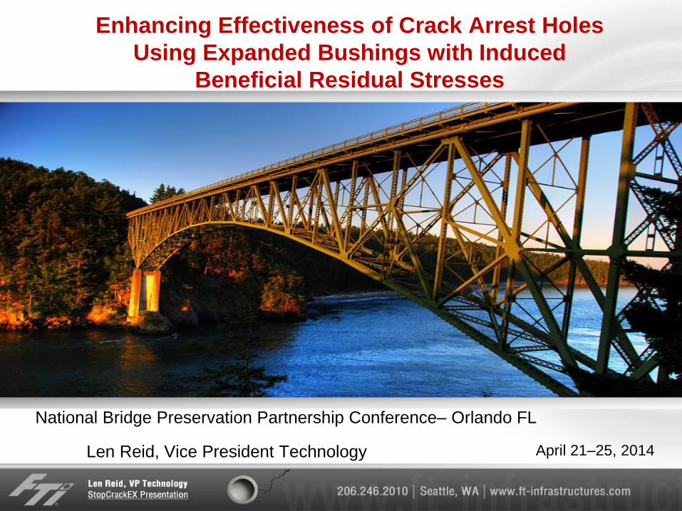
April 21–25, 2014 Enhancing Effectiveness of Crack Arrest Holes Using Expanded Bushings with Induced Beneficial Residual Stresses Len Reid, Vice President Technology National Bridge Preservation Partnership Conference– Orlando FL
Transcript of Enhancing Effectiveness of Crack Arrest Holes Using ... · PDF file• Could lead to load...
April 21–25, 2014
Enhancing Effectiveness of Crack Arrest Holes
Using Expanded Bushings with Induced
Beneficial Residual Stresses
Len Reid, Vice President Technology
National Bridge Preservation Partnership Conference– Orlando FL
Objective
• Discuss steel bridge cracking problem
• Current methods to arrest cracks
• Introduce expanded bushing methodology to enhance
crack arrest holes
• Explain the derivation from aerospace hole cold
expansion method
• Used to extend the fatigue life and damage tolerance life of
aircraft structures.
• Show by test and analysis how the StopCrackEX
enhanced drill stop method arrests the growth of two
different orientation cracks in test coupons
• Show how it could be an effective adjunct to NDE and
included as part of bridge preservation and repair
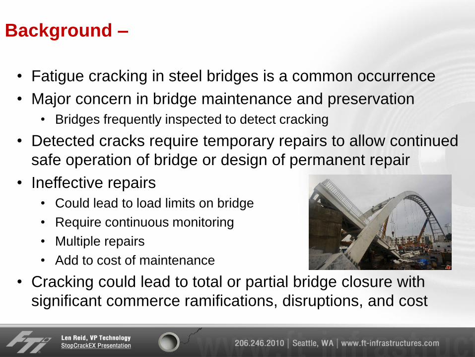
Background –
• Fatigue cracking in steel bridges is a common occurrence
• Major concern in bridge maintenance and preservation
• Bridges frequently inspected to detect cracking
• Detected cracks require temporary repairs to allow continued
safe operation of bridge or design of permanent repair
• Ineffective repairs
• Could lead to load limits on bridge
• Require continuous monitoring
• Multiple repairs
• Add to cost of maintenance
• Cracking could lead to total or partial bridge closure with
significant commerce ramifications, disruptions, and cost
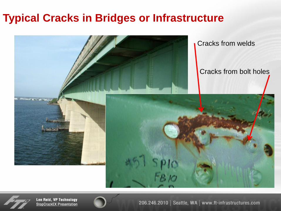
Typical Cracks in Bridges or Infrastructure
Cracks from welds
Cracks from bolt holes
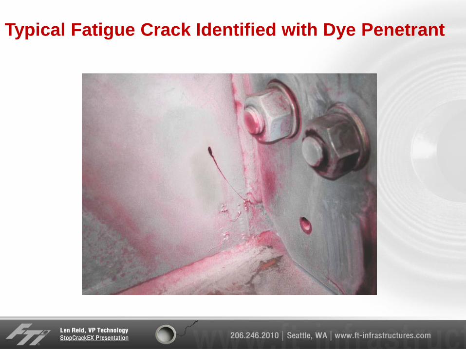
Typical Fatigue Crack Identified with Dye Penetrant
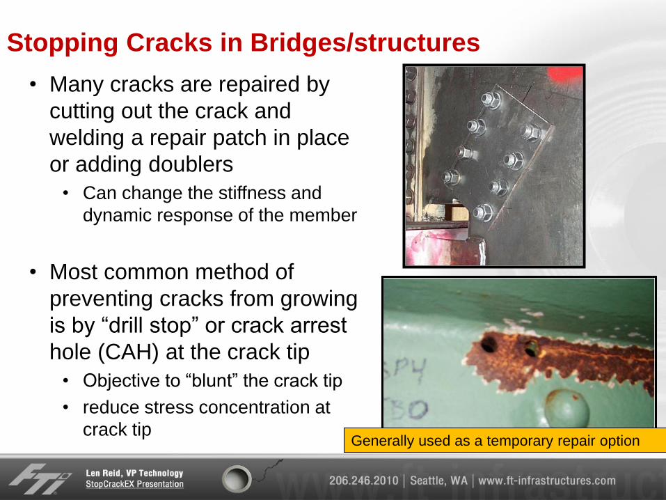
Stopping Cracks in Bridges/structures
• Many cracks are repaired by
cutting out the crack and
welding a repair patch in place
or adding doublers
• Can change the stiffness and
dynamic response of the member
• Most common method of
preventing cracks from growing
is by “drill stop” or crack arrest
hole (CAH) at the crack tip
• Objective to “blunt” the crack tip
• reduce stress concentration at
crack tip
Generally used as a temporary repair option
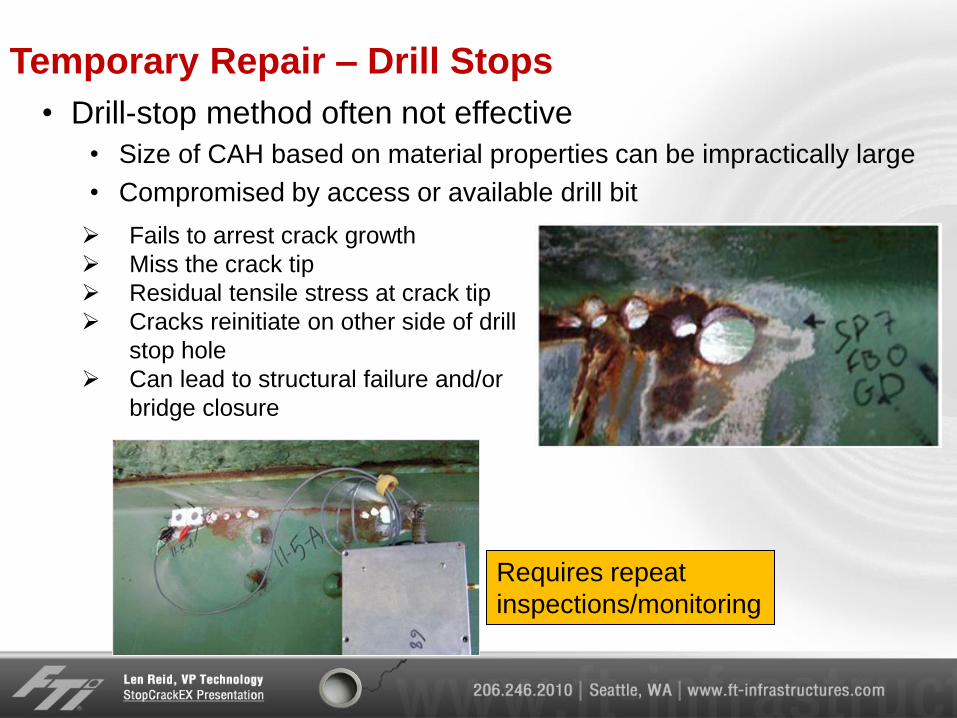
Temporary Repair – Drill Stops
• Drill-stop method often not effective
• Size of CAH based on material properties can be impractically large
• Compromised by access or available drill bit
Fails to arrest crack growth
Miss the crack tip
Residual tensile stress at crack tip
Cracks reinitiate on other side of drill
stop hole
Can lead to structural failure and/or
bridge closure
Requires repeat
inspections/monitoring
Methods Tried to Improve Crack Arrest Holes
• Variety of methods tried
• Installing interference fit bolts or fasteners
a) Method relies on effective interference
• Pre-stressing crack tip with hammer blows
• Surface treatment methods
a) Ultrasonic impact
b) Shot peening around hole
• Pre-stressing hole using novel piezoelectric method
• Application on bridges not practical
• No convenient way of verifying hole was correctly expanded/treated
• Most methods shown to have little or no effect in retarding crack growth
• Especially if driving stresses are high or crack is near critical crack length
• No convenient way to measure effectiveness of temporary repair
• Does not eliminate need for ongoing monitoring/inspection
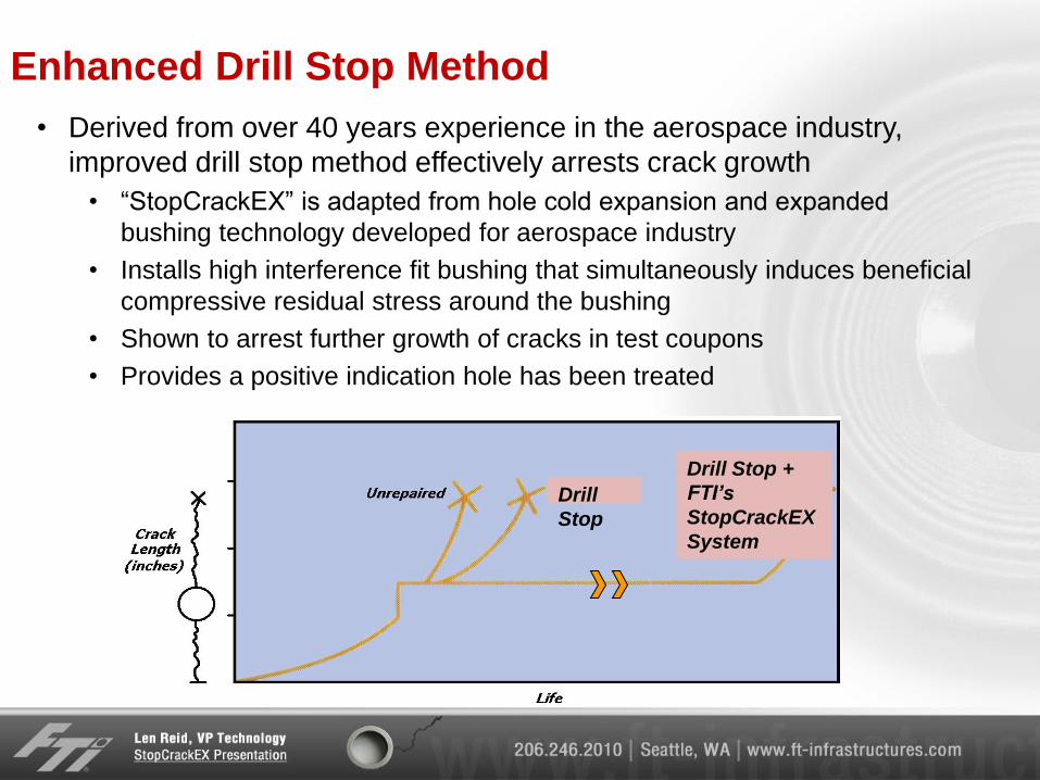
Enhanced Drill Stop Method
• Derived from over 40 years experience in the aerospace industry,
improved drill stop method effectively arrests crack growth
• “StopCrackEX” is adapted from hole cold expansion and expanded
bushing technology developed for aerospace industry
• Installs high interference fit bushing that simultaneously induces beneficial
compressive residual stress around the bushing
• Shown to arrest further growth of cracks in test coupons
• Provides a positive indication hole has been treated
Drill
Stop
Drill Stop +
FTI’s
StopCrackEX
System
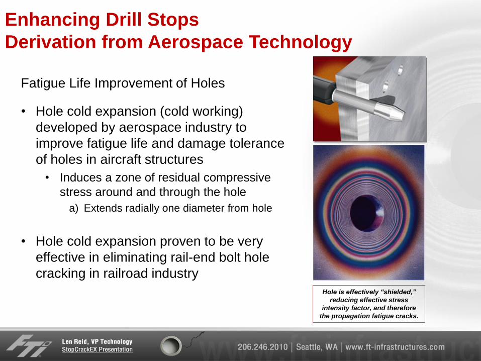
Enhancing Drill Stops
Derivation from Aerospace Technology
• Hole cold expansion (cold working)
developed by aerospace industry to
improve fatigue life and damage tolerance
of holes in aircraft structures
• Induces a zone of residual compressive
stress around and through the hole
a) Extends radially one diameter from hole
• Hole cold expansion proven to be very
effective in eliminating rail-end bolt hole
cracking in railroad industry
Hole is effectively “shielded,”
reducing effective stress
intensity factor, and therefore
the propagation fatigue cracks.
Fatigue Life Improvement of Holes
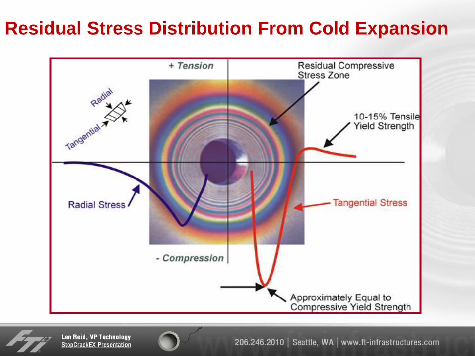
Residual Stress Distribution From Cold Expansion
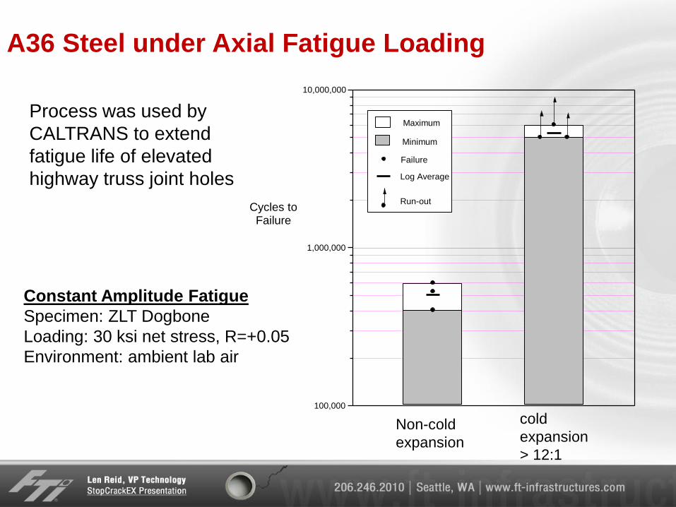
A36 Steel under Axial Fatigue Loading
100,000
1,000,000
10,000,000
Cycles toFailure
Maximum
Minimum
Log Average
Failure
Run-out
Constant Amplitude Fatigue
Specimen: ZLT Dogbone
Loading: 30 ksi net stress, R=+0.05
Environment: ambient lab air
Non-cold
expansion
cold
expansion
> 12:1
Process was used by
CALTRANS to extend
fatigue life of elevated
highway truss joint holes
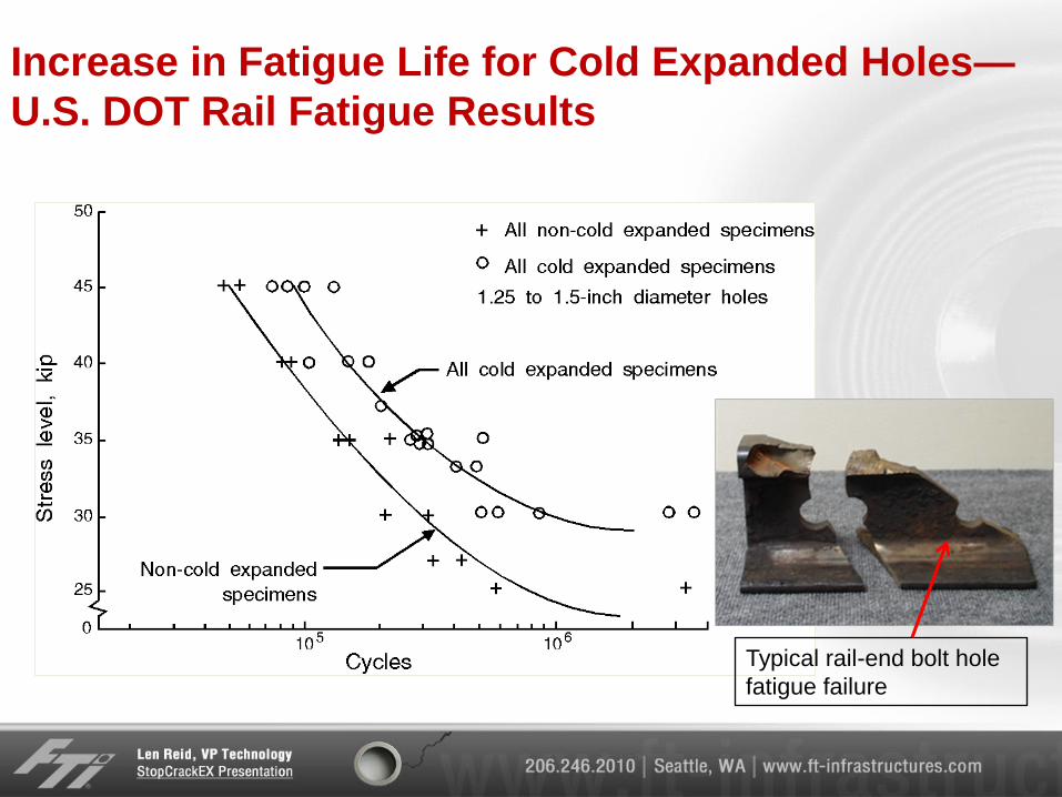
Increase in Fatigue Life for Cold Expanded Holes—
U.S. DOT Rail Fatigue Results
Typical rail-end bolt hole
fatigue failure
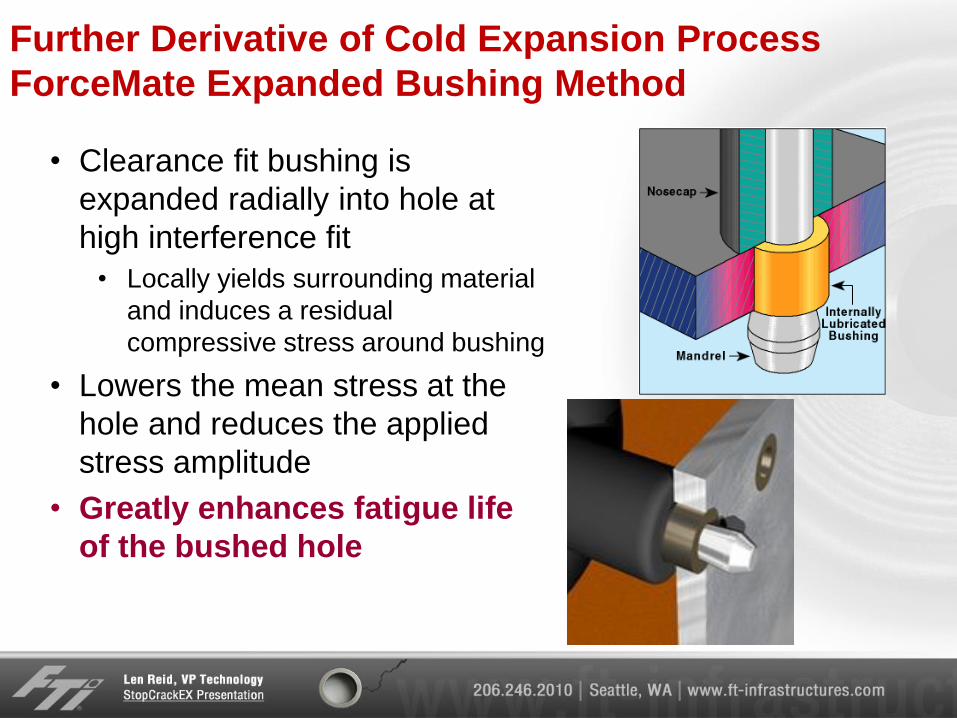
Further Derivative of Cold Expansion Process
ForceMate Expanded Bushing Method
• Clearance fit bushing is
expanded radially into hole at
high interference fit
• Locally yields surrounding material
and induces a residual
compressive stress around bushing
• Lowers the mean stress at the
hole and reduces the applied
stress amplitude
• Greatly enhances fatigue life
of the bushed hole
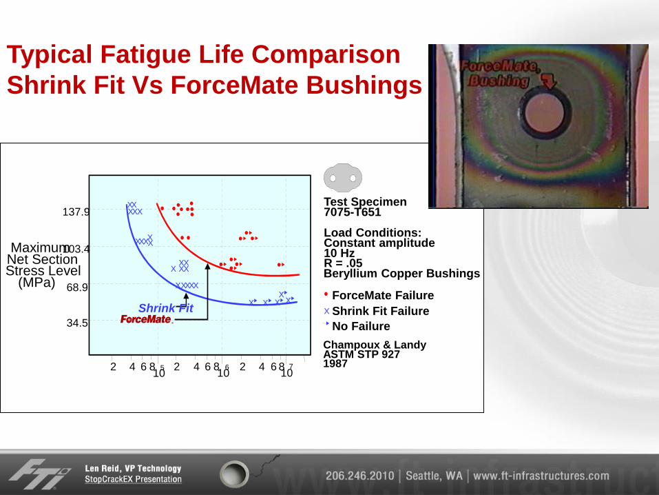
Typical Fatigue Life Comparison
Shrink Fit Vs ForceMate Bushings
137.9
103.4 Maximum Net Section Stress Level
(MPa) 68.9
34.5
2 2 2 4 4 4 6 6 6 8 8 8 10
5 10
6 10
7
Shrink Fit
X
X X
X
X X X X X
X X X X
X X X
X
X X X X
X
X
X X X
Test Specimen 7075-T651
Load Conditions: Constant amplitude 10 Hz R = .05 Beryllium Copper Bushings
ForceMate Failure
Shrink Fit Failure
No Failure
Champoux & Landy ASTM STP 927 1987
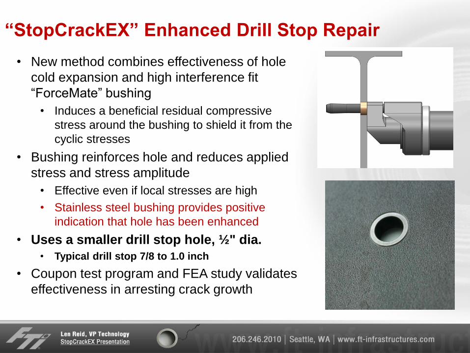
“StopCrackEX” Enhanced Drill Stop Repair
• New method combines effectiveness of hole
cold expansion and high interference fit
“ForceMate” bushing
• Induces a beneficial residual compressive
stress around the bushing to shield it from the
cyclic stresses
• Bushing reinforces hole and reduces applied
stress and stress amplitude
• Effective even if local stresses are high
• Stainless steel bushing provides positive
indication that hole has been enhanced
• Uses a smaller drill stop hole, ½" dia.
• Typical drill stop 7/8 to 1.0 inch
• Coupon test program and FEA study validates
effectiveness in arresting crack growth
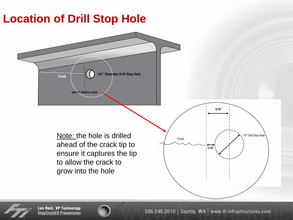
Location of Drill Stop Hole
Note: the hole is drilled
ahead of the crack tip to
ensure it captures the tip
to allow the crack to
grow into the hole
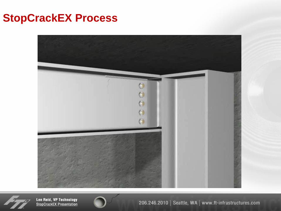
StopCrackEX Process
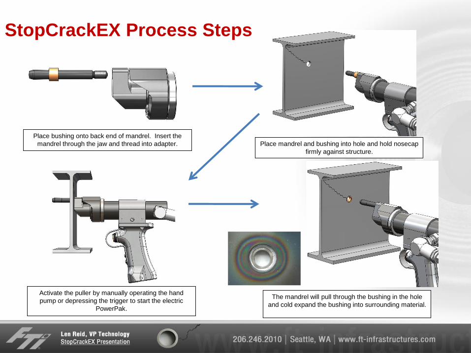
StopCrackEX Process Steps
Place bushing onto back end of mandrel. Insert the
mandrel through the jaw and thread into adapter. Place mandrel and bushing into hole and hold nosecap
firmly against structure.
Activate the puller by manually operating the hand
pump or depressing the trigger to start the electric
PowerPak.
The mandrel will pull through the bushing in the hole
and cold expand the bushing into surrounding material.
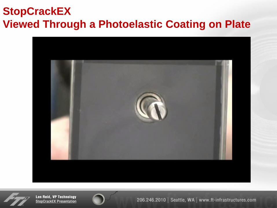
StopCrackEX
Viewed Through a Photoelastic Coating on Plate
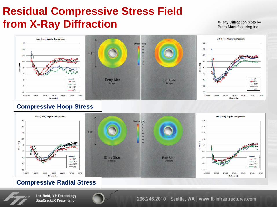
Residual Compressive Stress Field
from X-Ray Diffraction X-Ray Diffraction plots by
Proto Manufacturing Inc
Compressive Hoop Stress
Compressive Radial Stress
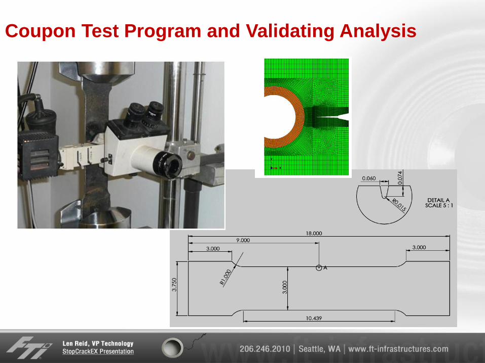
Coupon Test Program and Validating Analysis
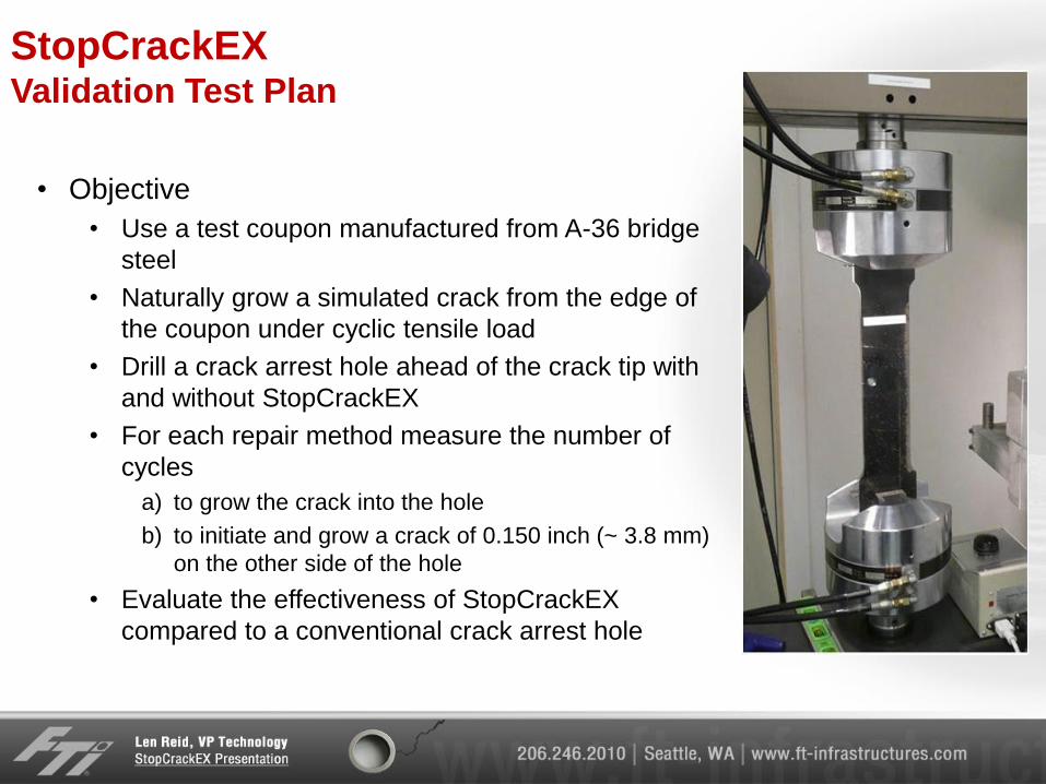
StopCrackEX Validation Test Plan
• Objective
• Use a test coupon manufactured from A-36 bridge
steel
• Naturally grow a simulated crack from the edge of
the coupon under cyclic tensile load
• Drill a crack arrest hole ahead of the crack tip with
and without StopCrackEX
• For each repair method measure the number of
cycles
a) to grow the crack into the hole
b) to initiate and grow a crack of 0.150 inch (~ 3.8 mm)
on the other side of the hole
• Evaluate the effectiveness of StopCrackEX
compared to a conventional crack arrest hole
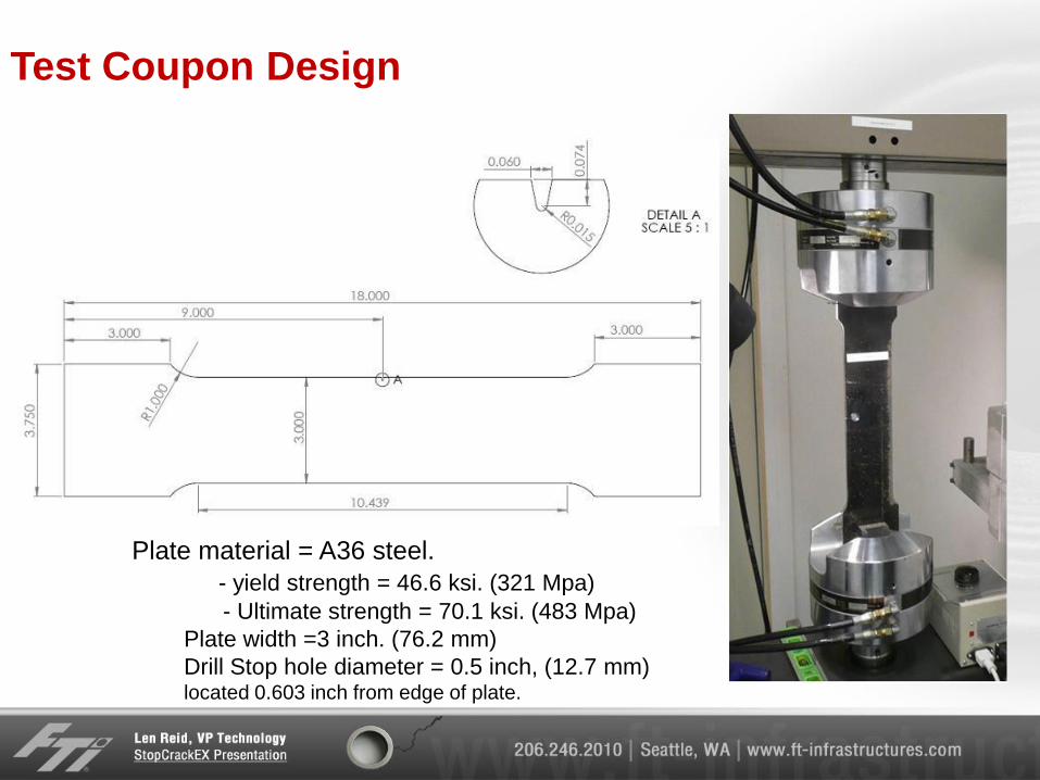
Test Coupon Design
Plate material = A36 steel.
- yield strength = 46.6 ksi. (321 Mpa)
- Ultimate strength = 70.1 ksi. (483 Mpa)
Plate width =3 inch. (76.2 mm)
Drill Stop hole diameter = 0.5 inch, (12.7 mm) located 0.603 inch from edge of plate.
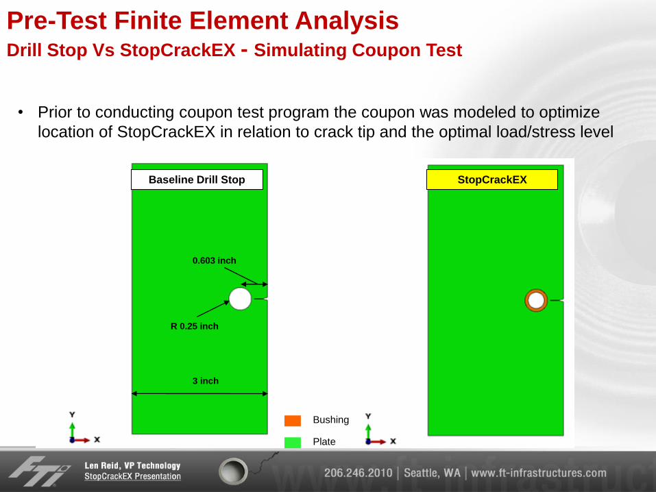
Pre-Test Finite Element Analysis Drill Stop Vs StopCrackEX - Simulating Coupon Test
Plate
Bushing
3 inch
0.603 inch
R 0.25 inch
Baseline Drill Stop StopCrackEX
• Prior to conducting coupon test program the coupon was modeled to optimize
location of StopCrackEX in relation to crack tip and the optimal load/stress level
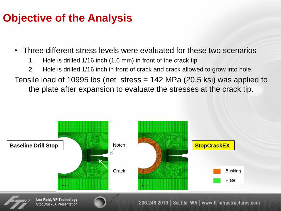
Objective of the Analysis
• Three different stress levels were evaluated for these two scenarios
1. Hole is drilled 1/16 inch (1.6 mm) in front of the crack tip
2. Hole is drilled 1/16 inch in front of crack and crack allowed to grow into hole.
Tensile load of 10995 lbs (net stress = 142 MPa (20.5 ksi) was applied to
the plate after expansion to evaluate the stresses at the crack tip.
Baseline Drill Stop StopCrackEX Notch
Crack
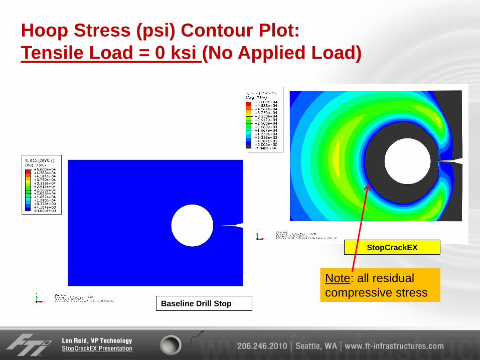
Hoop Stress (psi) Contour Plot:
Tensile Load = 0 ksi (No Applied Load)
StopCrackEX
Baseline Drill Stop
Note: all residual
compressive stress
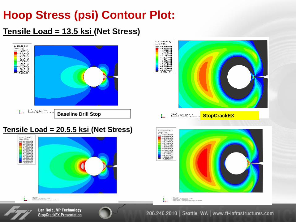
Hoop Stress (psi) Contour Plot:
StopCrackEX Baseline Drill Stop
Tensile Load = 13.5 ksi (Net Stress)
Tensile Load = 20.5.5 ksi (Net Stress)
Plate
Bushing
Notch
Crack
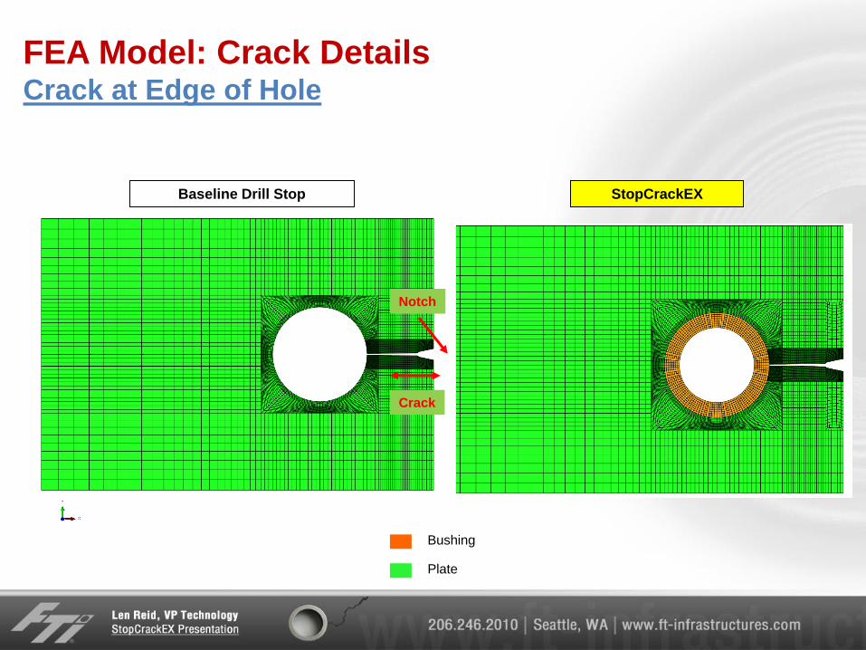
FEA Model: Crack Details Crack at Edge of Hole
StopCrackEX Baseline Drill Stop
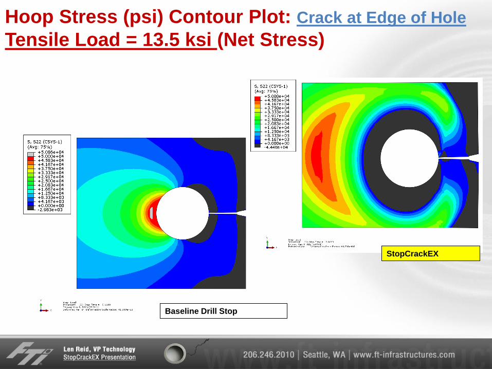
Hoop Stress (psi) Contour Plot: Crack at Edge of Hole
Tensile Load = 13.5 ksi (Net Stress)
StopCrackEX
Baseline Drill Stop
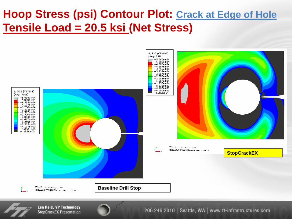
Hoop Stress (psi) Contour Plot: Crack at Edge of Hole
Tensile Load = 20.5 ksi (Net Stress)
StopCrackEX
Baseline Drill Stop
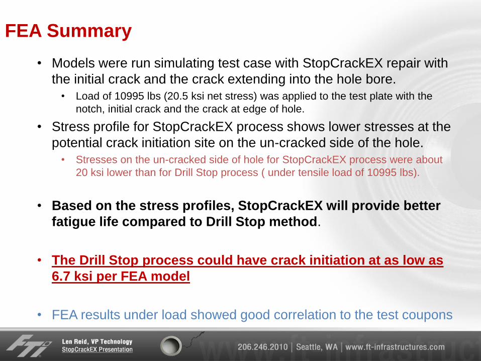
FEA Summary
• Models were run simulating test case with StopCrackEX repair with
the initial crack and the crack extending into the hole bore.
• Load of 10995 lbs (20.5 ksi net stress) was applied to the test plate with the
notch, initial crack and the crack at edge of hole.
• Stress profile for StopCrackEX process shows lower stresses at the
potential crack initiation site on the un-cracked side of the hole.
• Stresses on the un-cracked side of hole for StopCrackEX process were about
20 ksi lower than for Drill Stop process ( under tensile load of 10995 lbs).
• Based on the stress profiles, StopCrackEX will provide better
fatigue life compared to Drill Stop method.
• The Drill Stop process could have crack initiation at as low as
6.7 ksi per FEA model
• FEA results under load showed good correlation to the test coupons
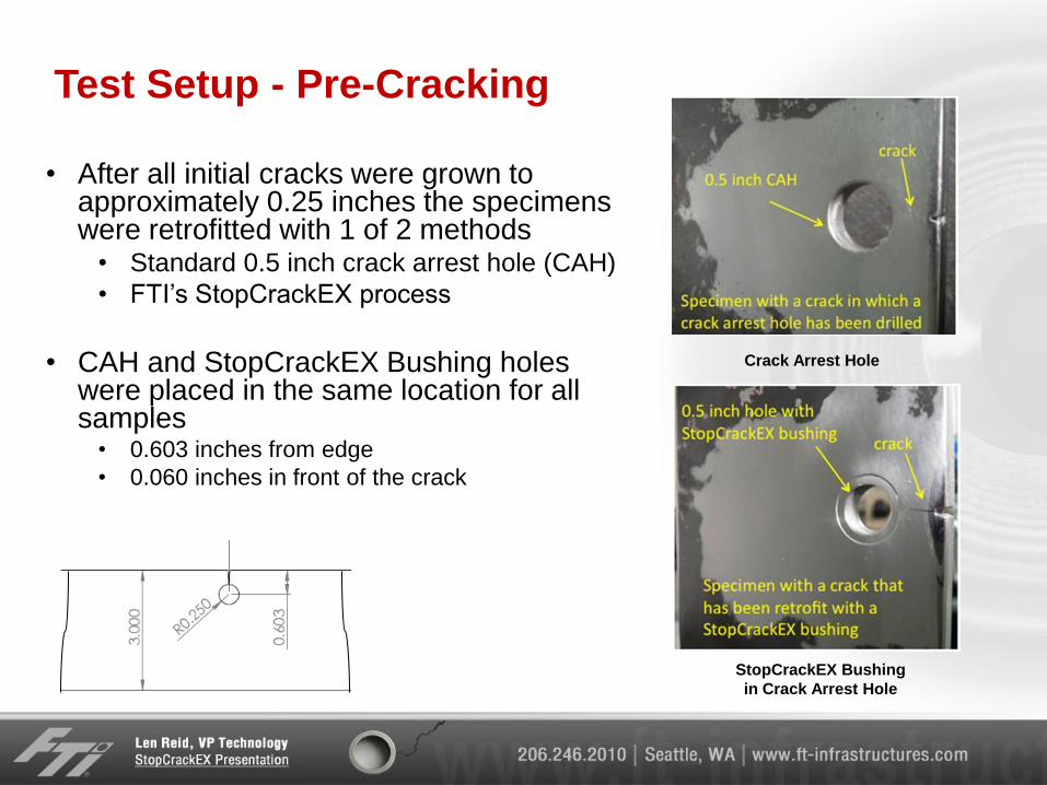
Test Setup - Pre-Cracking
• After all initial cracks were grown to approximately 0.25 inches the specimens were retrofitted with 1 of 2 methods
• Standard 0.5 inch crack arrest hole (CAH)
• FTI’s StopCrackEX process
• CAH and StopCrackEX Bushing holes were placed in the same location for all samples
• 0.603 inches from edge
• 0.060 inches in front of the crack
Crack Arrest Hole
StopCrackEX Bushing
in Crack Arrest Hole
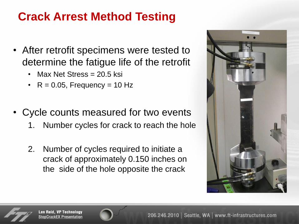
Crack Arrest Method Testing
• After retrofit specimens were tested to
determine the fatigue life of the retrofit • Max Net Stress = 20.5 ksi
• R = 0.05, Frequency = 10 Hz
• Cycle counts measured for two events
1. Number cycles for crack to reach the hole
2. Number of cycles required to initiate a
crack of approximately 0.150 inches on
the side of the hole opposite the crack
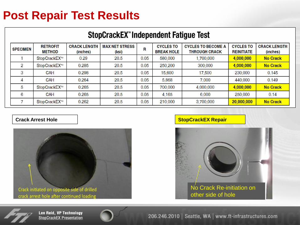
Post Repair Test Results
No Crack Re-initiation on
other side of hole
Crack Arrest Hole StopCrackEX Repair
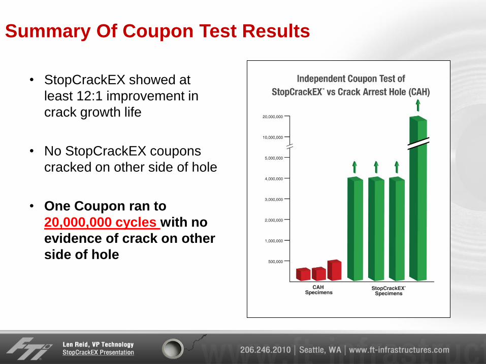
Summary Of Coupon Test Results
• StopCrackEX showed at
least 12:1 improvement in
crack growth life
• No StopCrackEX coupons
cracked on other side of hole
• One Coupon ran to
20,000,000 cycles with no
evidence of crack on other
side of hole
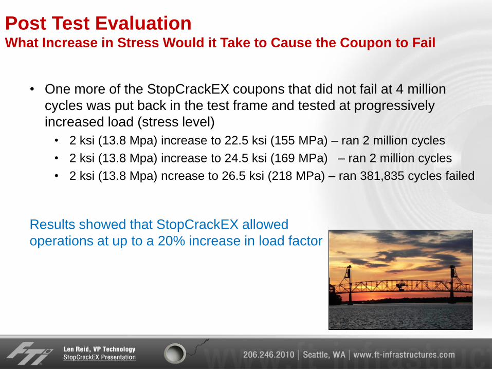
Post Test Evaluation What Increase in Stress Would it Take to Cause the Coupon to Fail
• One more of the StopCrackEX coupons that did not fail at 4 million
cycles was put back in the test frame and tested at progressively
increased load (stress level)
• 2 ksi (13.8 Mpa) increase to 22.5 ksi (155 MPa) – ran 2 million cycles
• 2 ksi (13.8 Mpa) increase to 24.5 ksi (169 MPa) – ran 2 million cycles
• 2 ksi (13.8 Mpa) ncrease to 26.5 ksi (218 MPa) – ran 381,835 cycles failed
Results showed that StopCrackEX allowed
operations at up to a 20% increase in load factor
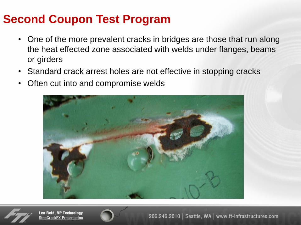
Second Coupon Test Program
• One of the more prevalent cracks in bridges are those that run along
the heat effected zone associated with welds under flanges, beams
or girders
• Standard crack arrest holes are not effective in stopping cracks
• Often cut into and compromise welds
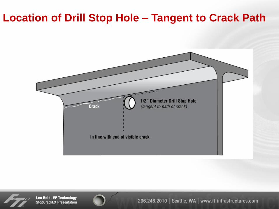
Location of Drill Stop Hole – Tangent to Crack Path
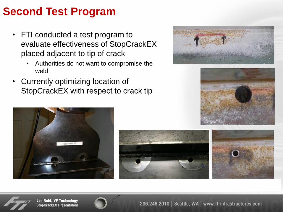
Second Test Program
• FTI conducted a test program to
evaluate effectiveness of StopCrackEX
placed adjacent to tip of crack
• Authorities do not want to compromise the
weld
• Currently optimizing location of
StopCrackEX with respect to crack tip
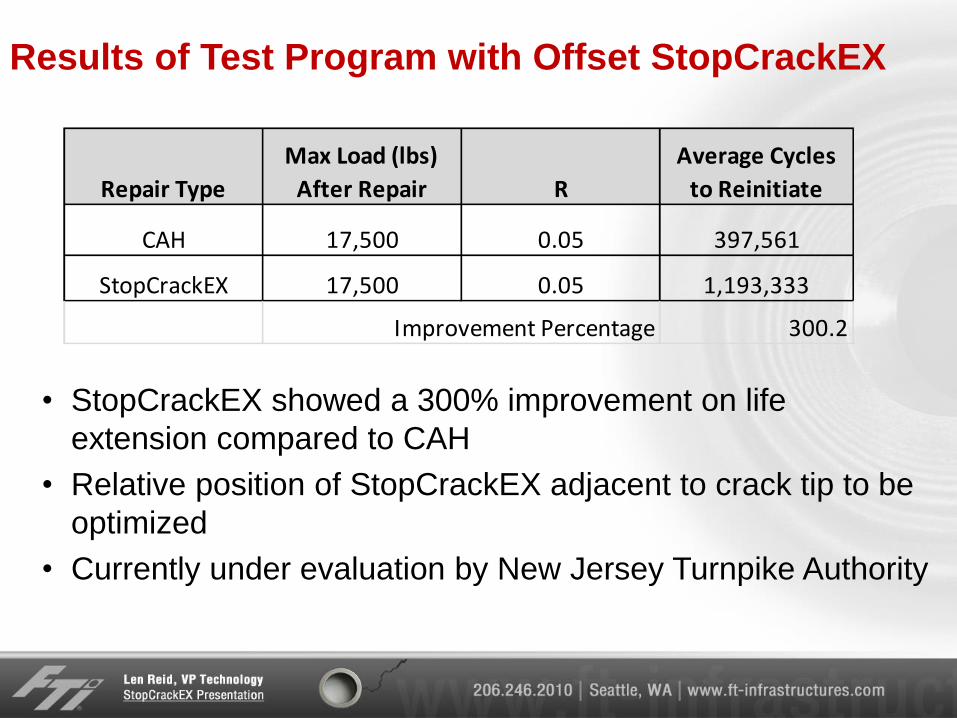
Results of Test Program with Offset StopCrackEX
• StopCrackEX showed a 300% improvement on life
extension compared to CAH
• Relative position of StopCrackEX adjacent to crack tip to be
optimized
• Currently under evaluation by New Jersey Turnpike Authority
Repair Type
Max Load (lbs)
After Repair R
Average Cycles
to Reinitiate
CAH 17,500 0.05 397,561
StopCrackEX 17,500 0.05 1,193,333
300.2Improvement Percentage
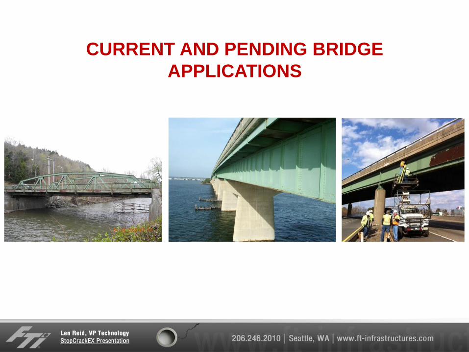
CURRENT AND PENDING BRIDGE
APPLICATIONS
44
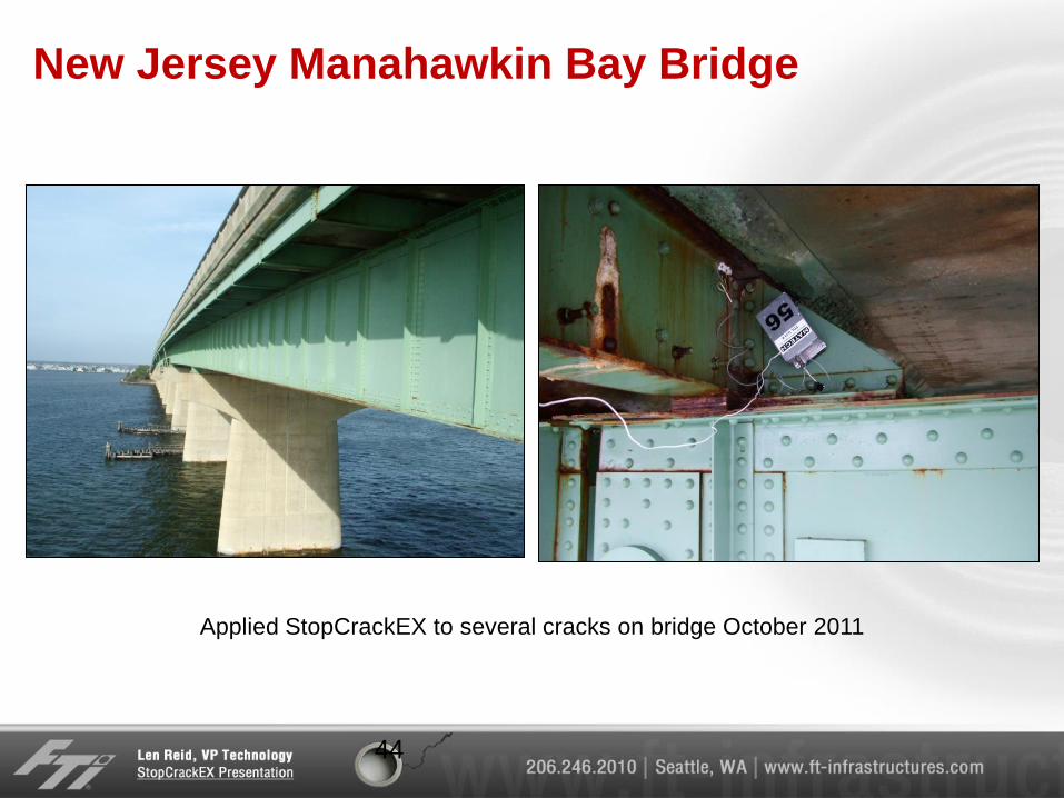
New Jersey Manahawkin Bay Bridge
Applied StopCrackEX to several cracks on bridge October 2011
45
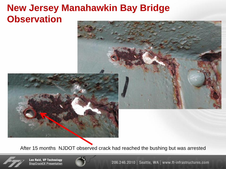
New Jersey Manahawkin Bay Bridge
Observation
After 15 months NJDOT observed crack had reached the bushing but was arrested
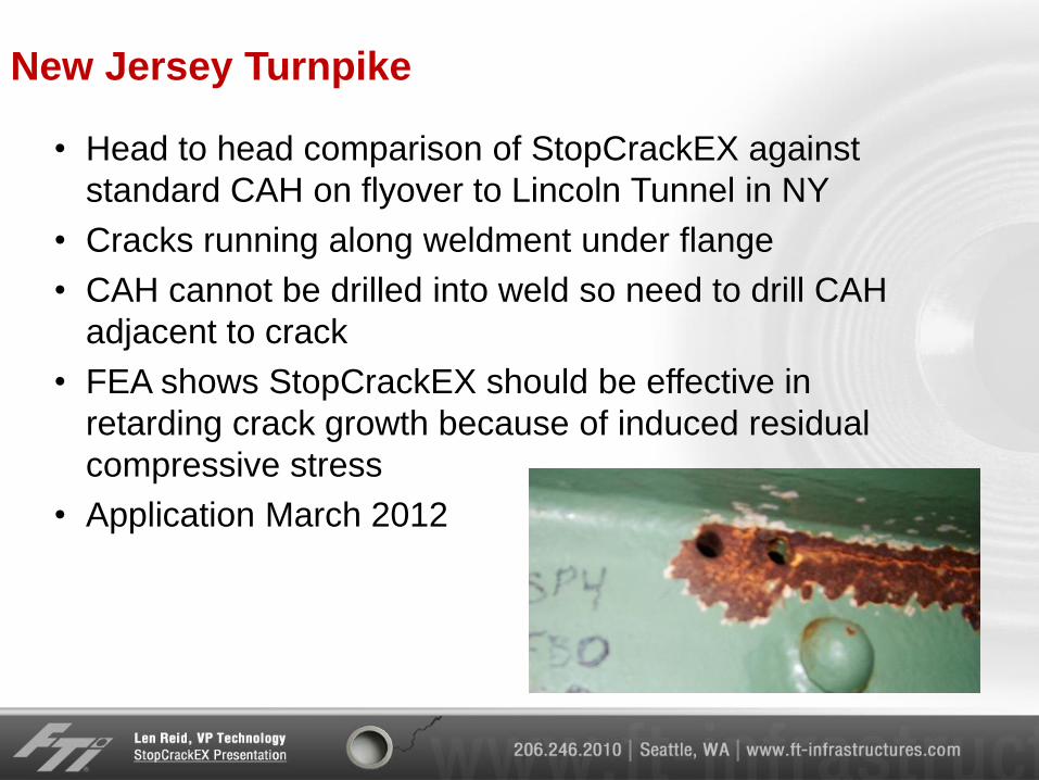
New Jersey Turnpike
• Head to head comparison of StopCrackEX against
standard CAH on flyover to Lincoln Tunnel in NY
• Cracks running along weldment under flange
• CAH cannot be drilled into weld so need to drill CAH
adjacent to crack
• FEA shows StopCrackEX should be effective in
retarding crack growth because of induced residual
compressive stress
• Application March 2012
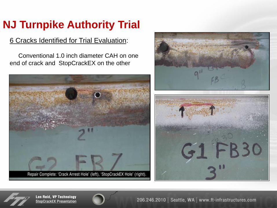
NJ Turnpike Authority Trial
6 Cracks Identified for Trial Evaluation:
Conventional 1.0 inch diameter CAH on one
end of crack and StopCrackEX on the other
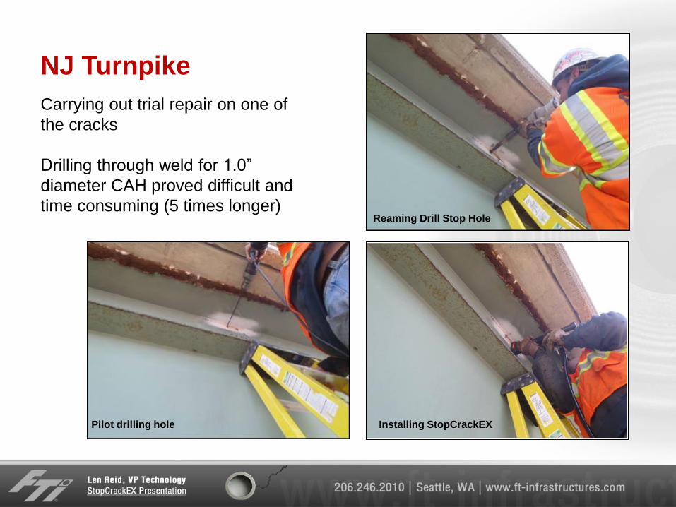
NJ Turnpike
Carrying out trial repair on one of
the cracks
Drilling through weld for 1.0”
diameter CAH proved difficult and
time consuming (5 times longer)
Installing StopCrackEX Pilot drilling hole
Reaming Drill Stop Hole
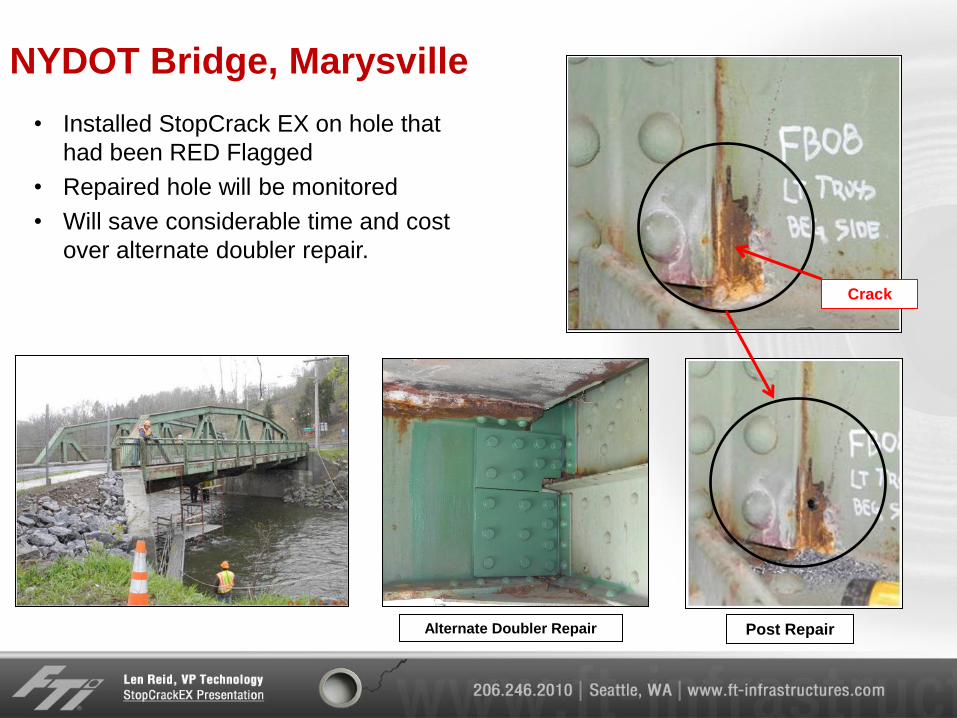
NYDOT Bridge, Marysville
• Installed StopCrack EX on hole that
had been RED Flagged
• Repaired hole will be monitored
• Will save considerable time and cost
over alternate doubler repair.
Crack
Post Repair Alternate Doubler Repair
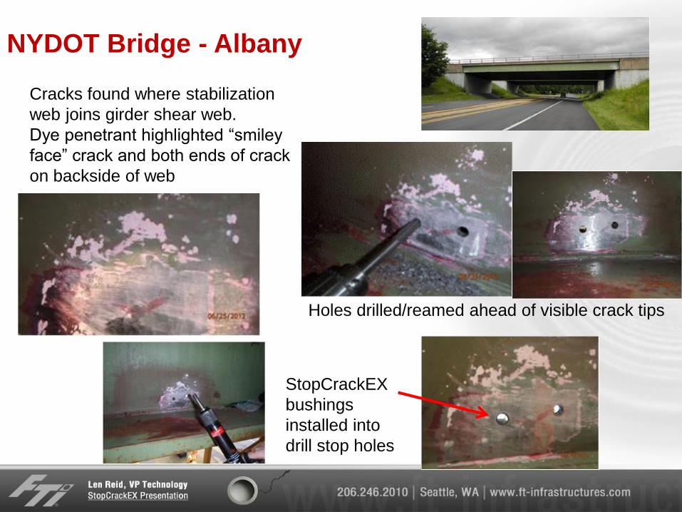
NYDOT Bridge - Albany
Cracks found where stabilization
web joins girder shear web.
Dye penetrant highlighted “smiley
face” crack and both ends of crack
on backside of web
Holes drilled/reamed ahead of visible crack tips
StopCrackEX
bushings
installed into
drill stop holes
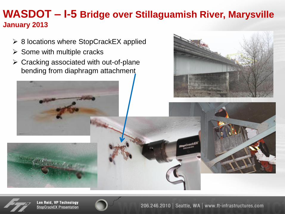
WASDOT – I-5 Bridge over Stillaguamish River, Marysville January 2013
8 locations where StopCrackEX applied
Some with multiple cracks
Cracking associated with out-of-plane
bending from diaphragm attachment
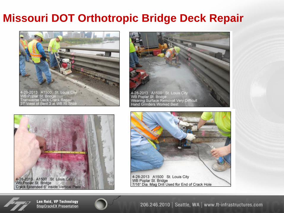
Missouri DOT Orthotropic Bridge Deck Repair
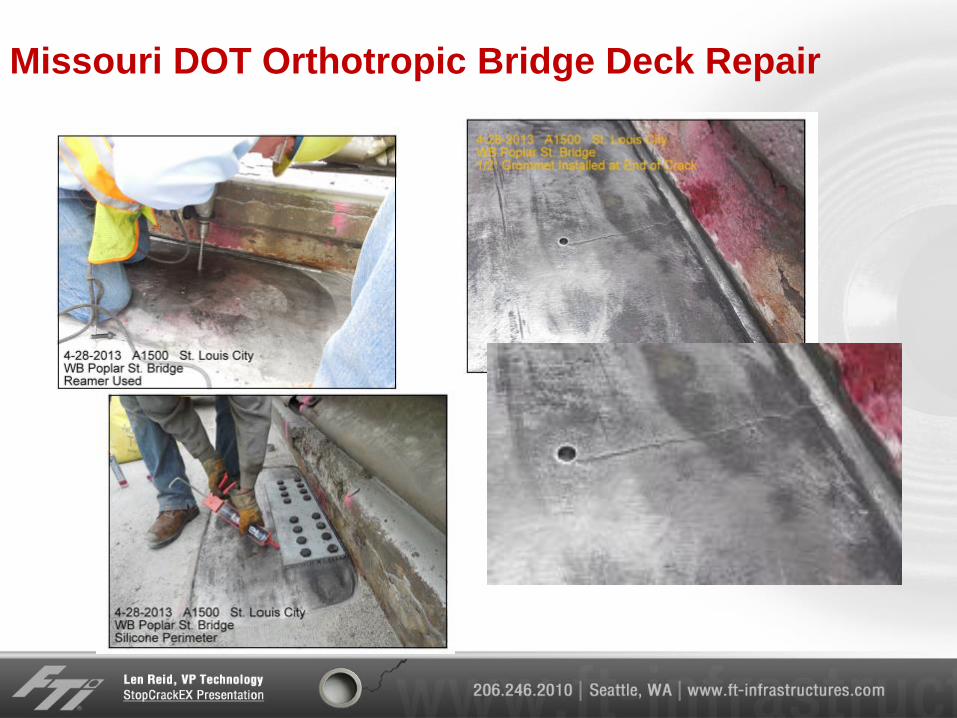
Missouri DOT Orthotropic Bridge Deck Repair
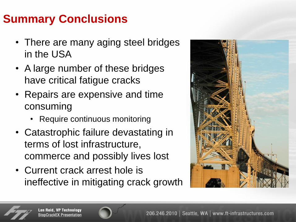
Summary Conclusions
• There are many aging steel bridges
in the USA
• A large number of these bridges
have critical fatigue cracks
• Repairs are expensive and time
consuming
• Require continuous monitoring
• Catastrophic failure devastating in
terms of lost infrastructure,
commerce and possibly lives lost
• Current crack arrest hole is
ineffective in mitigating crack growth
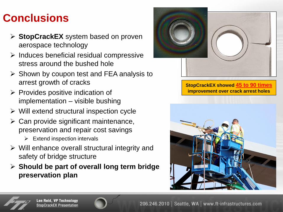
Conclusions
StopCrackEX system based on proven
aerospace technology
Induces beneficial residual compressive
stress around the bushed hole
Shown by coupon test and FEA analysis to
arrest growth of cracks
Provides positive indication of
implementation – visible bushing
Will extend structural inspection cycle
Can provide significant maintenance,
preservation and repair cost savings Extend inspection intervals
Will enhance overall structural integrity and
safety of bridge structure
Should be part of overall long term bridge
preservation plan
StopCrackEX showed 45 to 90 times improvement over crack arrest holes
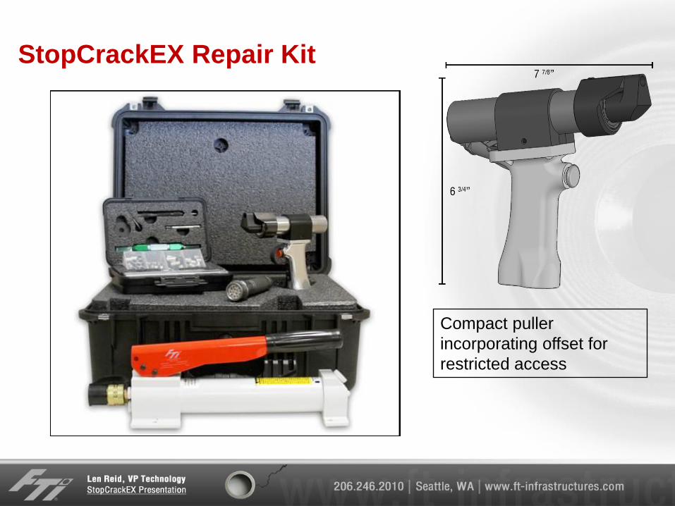
StopCrackEX Repair Kit
Compact puller
incorporating offset for
restricted access

Questions? Thank You!
Visit our website www.ft-infrastructures.com