
Oracle Fusion Applications Extensibility Guide for Developers Rel 7

Faculty of Computers & InformationDepartment of Computer Science
Enhancing Design of Extensibility inSoftware Applications
Using Interactive Design Pattern Recommendation
By
Tamer AbdElaziz AbdElmegid Mohamed YassenTeaching assistant at Computer Science Dept.,
Faculty of Computers & Information, HELWAN UNIVERSITY
Submitted to the Department of Computer Science in partial fulfillment of therequirements for the degree of MASTER OF SCIENCE in Computers and
Information (Computer Science Specialization)at
Faculty of Computers &Information, HELWAN UNIVERSITY, Cairo, Egypt.
Supervised by ................................................................................................................Prof. Dr. Mostafa Sami M. Mostafa
Professor of Computer Science,Member of HCI Lab, Faculty of Computers &Information,
HELWAN UNIVERSITY, Cairo, Egypt.Supervised by ................................................................................................................
Dr. Aya Sedky AdlyAssistant Professor, Faculty of Computers &Information,
HELWAN UNIVERSITY, Cairo, Egypt.
©HELWAN UNIVERSITY, ALL RIGHTS RESERVED.JULY 18, 2018.


i


LIST OF PUBLICATION
1. Tamer Abdelaziz, Aya Sedky, Bruno Rossi, and Mostafa-Sami M. Mostafa. "Identificationand Assessment of Software Design Pattern Violations".
iii


ABSTRACT
Software systems need to be extended in order to survive and software developer has toanswer this question, Is the application adaptable to meet new requirements?, if it isextensible, software developers will be able to grow and adapt the software to meet the
changing needs of business and customers, if not, the software developers might have to throw itout and start from scratch. Subsequently, the system design and implementations should takefuture growth of system requirements into consideration, and adapt to technological changesover time.
Extensibility, verification1 and validation2 as well as maintenance are key activities inthe software life cycle. During these activities, it is important to check the correctness of thedesign and implementation of a software product against some predefined criteria to detect andto correct software defects early in the development process and, thus, to reduce costs.
Using Object Oriented Programming (OOP) and Design Patterns (DP) knowledge to developapplications in a way that they can be changed and/or enhanced with minimum effort and in aclean, elegant, and efficient manner. In addition, the developers usually need a lot of experienceand a good understanding of a given system to avoid missing possibilities of using design patternsand produce code containing design smells3, as well as, they need an enormous effort to assesspattern implementations in order to identify design patterns violations and determine whetherthe pattern definition characteristics are met or not. If design pattern implementations do notconform to their definitions, they are considered as a violation. Software aging and the lack ofexperience of developers are two origins of design pattern violations. Consequently, the validationof design patterns violations has gained more relevance as part of re-engineering processes inorder to preserve, extend, reuse software projects in rapid development environments.
Currently, several approaches have been developed to detect design pattern instances,but there has been little work done in creating an automated approach to identify and tovalidate design pattern violations. At the end of this research we propose a tool for DesignPattern Violations Identification and Assessment (DPVIA). It has the ability to identify softwaredesign pattern violations and report the conformance score of pattern instance implementationstowards a set of predefined characteristics for any design pattern definition of whether Gangof Four (GoF) design patterns or custom pattern designed by software developer. Moreover, we
1Verification is to check whether the software conforms to specifications. Have we built the software right ?2Validation is to check whether software meets the customer expectations and requirements. Have we built the
right software ?3design smells are structures in the design that indicate violation of fundamental design principles and negatively
impact design quality.
v

validate the proposed approach DPVIA using two evaluation experiments supported by manualresults reviews. As well as, we verified the detected violations if they should be counted in theconformance scoring or not based on extracting of entities relation from System RequirementSpecifications (SRS) using the Stanford CoreNLP Natural Language Processing Toolkit. Finally,in order to assess the functionality of the proposed approach, DPVIA is evaluated with a datasetcontaining 5,679,964 Lines of Code (LoC) among 28,669 Java files in 15 open-source projects.the selected open-source projects extensively and systematically employing design patterns, todetermine design pattern violations, and the results can be used by software architects to developbest practices while using design patterns.
Keywords: Extensible design, software re-engineering, GoF design pattern, software design patterndecay, design rot, design violations, pattern detection, design assessment, design pattern recommendation,natural language processing.
vi

DEDICATION AND ACKNOWLEDGEMENTS
F irstly, I am grateful to the ALLAH who guided and gave me the power to present this work.And I ask ALLAH to guide me to the straight path and benefit me with useful science inthis life and the hereafter.
I would like to express my sincere gratitude to my supervisor Prof. Dr. Mostafa Sami M.Mostafa for the continuous support of my Master study and related research, for his patience,motivation, and immense knowledge. His guidance helped me in all the time of research andwriting of this thesis. I could not have imagined having a better supervisor and mentor for myMaster study.
My sincere thanks also goes to my advisor Dr. Aya Sedky Adly, her office was always openwhenever I ran into a trouble spot or had a question about my research or writing. I am gratefulto her patience and support in overcoming numerous obstacles I have been facing through myresearch.
Besides my advisors, I would like to thank Prof. Bruno Rossi of Faculty of Informatics,Masaryk University, Czech Republic, who provided me an opportunity to join his team as exchangestudent, and who gave access to the laboratory and research facilities. I am extremely thankfuland indebted to him for sharing expertise, and sincere and valuable guidance and encouragementextended to me.
I am grateful to the staff members of Faculty of Computers and Information, HelwanUniversity for enlightening me the first glance of research. Also I thank my fellow labmates infor the stimulating discussions, and for the sleepless nights we were working together beforedeadlines.
Last but not the least, I would like to thank my family: my parents, my brother and mysister for supporting me spiritually throughout writing this thesis and my life in general. Also Ithank my friends and my students, this accomplishment would not have been possible withoutthem. Thank you.
vii


AUTHOR’S DECLARATION
I declare that the research described in this thesis was carried out at the Facultyof Computers & Information - Helwan University, Cairo, Egypt. This thesis wascarried out in accordance with the regulations of Helwan University. The work
is original except where indicated by special reference in the text and no part of thethesis has been submitted for any other degree. This thesis has not been presented toany other university for examination either in the Arab Republic of Egypt or abroad.
Copyright © 2018 by Tamer Abdelaziz Abdelmegid Mohamed Yassen, Allrights reserved. No part of this publication may be reproduced or transmittedin any form or by any means, electronic or mechanical, including photocopy,
recording, or any information storage and retrieval system, without permission inwriting from the author. Trademarks in this publication are the property of theirrespective owners.
SIGNED: .................................................... DATE: ..........................................
ix


LIST OF ABBREVIATIONS
OOP Object Oriented Programming
DP Design Patterns
GoF Gang of Four Design Patterns
NLP Natural Language Processing
AST Abstract Syntax Tree
OpenIE Open Information Extraction
DPVIA Design Pattern Violations Identification and Assessment
xi


TABLE OF CONTENTS
Page
List of Tables xv
List of Figures xvii
1 Introduction 11.1 Research Area Overview . . . . . . . . . . . . . . . . . . . . . . . . . . . . . . . . . . . 1
1.2 Research Problem . . . . . . . . . . . . . . . . . . . . . . . . . . . . . . . . . . . . . . . 4
1.3 Research Motivation . . . . . . . . . . . . . . . . . . . . . . . . . . . . . . . . . . . . . 5
1.4 Research Objective . . . . . . . . . . . . . . . . . . . . . . . . . . . . . . . . . . . . . . 6
1.5 Thesis Outline . . . . . . . . . . . . . . . . . . . . . . . . . . . . . . . . . . . . . . . . . 6
2 Technical Background and Related Work 92.1 Technical Background . . . . . . . . . . . . . . . . . . . . . . . . . . . . . . . . . . . . 9
2.1.1 Software Design Extensibility . . . . . . . . . . . . . . . . . . . . . . . . . . . 9
2.1.1.1 Characteristics of Extensibility Mechanisms . . . . . . . . . . . . 10
2.1.1.2 Classification of Extensibility Mechanisms . . . . . . . . . . . . . 11
2.1.1.3 How to apply Extensibility ? . . . . . . . . . . . . . . . . . . . . . . 12
2.1.2 Design Patterns . . . . . . . . . . . . . . . . . . . . . . . . . . . . . . . . . . . . 13
2.1.3 Software Design Decay . . . . . . . . . . . . . . . . . . . . . . . . . . . . . . . 17
2.2 Related Work . . . . . . . . . . . . . . . . . . . . . . . . . . . . . . . . . . . . . . . . . . 19
2.2.1 Design Pattern Detection Tools . . . . . . . . . . . . . . . . . . . . . . . . . . 19
2.2.1.1 Tsantalis Design Pattern Detection (Tsantalis DPD) . . . . . . . . 20
2.2.1.2 Pattern Inference and recOvery Tool (Pinot Tool) . . . . . . . . . . 20
2.2.1.3 Eclipse plug-in for design Pattern Analysis and Detection (ePAD
Tool) . . . . . . . . . . . . . . . . . . . . . . . . . . . . . . . . . . . . . 21
2.2.1.4 MARPLE for Design Pattern Detection (MARPLE-DPD) . . . . . 21
2.2.1.5 A Design Pattern Detection Tool for Code Reuse (DP-CoRe Tool) 22
2.2.2 Design Pattern Assessment Tools . . . . . . . . . . . . . . . . . . . . . . . . . 22
2.3 Round-trip Engineering . . . . . . . . . . . . . . . . . . . . . . . . . . . . . . . . . . . 24
2.3.1 UML Lab . . . . . . . . . . . . . . . . . . . . . . . . . . . . . . . . . . . . . . . . 25
xiii
TABLE OF CONTENTS
2.3.2 Altova UModel . . . . . . . . . . . . . . . . . . . . . . . . . . . . . . . . . . . . 25
2.3.3 IBM Rational Software Architect . . . . . . . . . . . . . . . . . . . . . . . . . 26
2.3.4 UML Round Trip Engineering Tools Comparison . . . . . . . . . . . . . . . . 26
2.3.5 Analysis of UML Design using XML Parsers . . . . . . . . . . . . . . . . . . 27
2.3.5.1 Extensible Markup Language (XML) . . . . . . . . . . . . . . . . . 28
2.3.5.2 XML Parser . . . . . . . . . . . . . . . . . . . . . . . . . . . . . . . . 29
2.4 Natural Language Processing Toolkits . . . . . . . . . . . . . . . . . . . . . . . . . . 30
2.4.1 Stanford CoreNLP - Natural language software Toolkit . . . . . . . . . . . . 31
2.4.2 NLTK - Natural Language Processing Toolkit . . . . . . . . . . . . . . . . . . 31
2.4.3 Natural Language Processing In Software Engineering . . . . . . . . . . . . 32
3 Proposed Approach 353.1 Design Patterns Detection . . . . . . . . . . . . . . . . . . . . . . . . . . . . . . . . . . 36
3.1.1 Representing Objects and Relationships . . . . . . . . . . . . . . . . . . . . . 36
3.1.2 Representing Design Patterns . . . . . . . . . . . . . . . . . . . . . . . . . . . 37
3.1.3 DP-CoRe Design Pattern Detection Algorithm . . . . . . . . . . . . . . . . . 45
3.1.3.1 Parsing Source Code to extract the Abstract Syntax Tree (AST) . 45
3.1.3.2 Detection of Design Pattern Candidates . . . . . . . . . . . . . . . 47
3.2 Design Pattern Violation Identification . . . . . . . . . . . . . . . . . . . . . . . . . . 48
3.2.1 Specify Design Pattern Predefined Characteristics . . . . . . . . . . . . . . . 49
3.2.2 Measurement of Conformance Scoring . . . . . . . . . . . . . . . . . . . . . . 53
3.3 Verification of the Initial Detected Violations . . . . . . . . . . . . . . . . . . . . . . 58
4 Implementation, Practical Experiments and Results 614.1 Implementation of the Proposed Approach . . . . . . . . . . . . . . . . . . . . . . . . 61
4.2 Practical Experiments . . . . . . . . . . . . . . . . . . . . . . . . . . . . . . . . . . . . 62
4.2.1 The First Practical Experiment . . . . . . . . . . . . . . . . . . . . . . . . . . 63
4.2.2 The Second Practical Experiment . . . . . . . . . . . . . . . . . . . . . . . . . 65
4.3 Discussion and Analysis of Results . . . . . . . . . . . . . . . . . . . . . . . . . . . . . 67
5 Conclusion and Future Work 735.1 Conclusion . . . . . . . . . . . . . . . . . . . . . . . . . . . . . . . . . . . . . . . . . . . 73
5.2 Threats to Validity . . . . . . . . . . . . . . . . . . . . . . . . . . . . . . . . . . . . . . 74
5.3 Future Work . . . . . . . . . . . . . . . . . . . . . . . . . . . . . . . . . . . . . . . . . . 75
A Appendix A - Results of DPVIA tool 77
Bibliography 93
xiv

LIST OF TABLES
TABLE Page
2.1 Creational patterns . . . . . . . . . . . . . . . . . . . . . . . . . . . . . . . . . . . . . . . . 15
2.2 Structural Patterns . . . . . . . . . . . . . . . . . . . . . . . . . . . . . . . . . . . . . . . . 16
2.3 Behavioral Patterns . . . . . . . . . . . . . . . . . . . . . . . . . . . . . . . . . . . . . . . . 17
2.4 UML Round Trip Engineering Tools . . . . . . . . . . . . . . . . . . . . . . . . . . . . . . 26
2.5 Comparison on XML Parser’s APIs . . . . . . . . . . . . . . . . . . . . . . . . . . . . . . . 28
3.1 Representing Design Pattern Abstraction Types . . . . . . . . . . . . . . . . . . . . . . . 37
3.2 Representing Design Pattern Directional Relationships Between Classes . . . . . . . . 37
3.3 SimpleFactory Design Pattern Predefined Characteristics . . . . . . . . . . . . . . . . . 50
3.4 Factory Method Design Pattern Predefined Characteristics . . . . . . . . . . . . . . . . 50
3.5 Adapter Design Pattern Predefined Characteristics . . . . . . . . . . . . . . . . . . . . . 51
3.6 Decorator Design Pattern Predefined Characteristics . . . . . . . . . . . . . . . . . . . . 51
3.7 Observer Design Pattern Predefined Characteristics . . . . . . . . . . . . . . . . . . . . 52
3.8 State Design Pattern Predefined Characteristics . . . . . . . . . . . . . . . . . . . . . . 52
3.9 Strategy Design Pattern Predefined Characteristics . . . . . . . . . . . . . . . . . . . . 53
3.10 Design Pattern Characteristics Comparing Scenarios . . . . . . . . . . . . . . . . . . . . 55
3.11 Strategy Candidate Instances . . . . . . . . . . . . . . . . . . . . . . . . . . . . . . . . . . 57
3.12 Measurement of Conformance Scoring Example . . . . . . . . . . . . . . . . . . . . . . . 58
4.1 Validating The Proposed Approach Over Head First Design Patterns Book Code Project 64
4.2 Validating The Conformance Algorithm Integrated With Tsantalis DPD Over Head
First Design Patterns Book Code Project . . . . . . . . . . . . . . . . . . . . . . . . . . . . 67
4.3 Data Set Of 15 Open Source Projects as input to DPVIA Tool . . . . . . . . . . . . . . . 70
4.4 Similarity Conformance Scores Reported by DPVIA Tool . . . . . . . . . . . . . . . . . . 70
xv

LIST OF FIGURES
FIGURE Page
2.1 An example of a RBML diagram on the left and a UML instance on the right [1] . . . 23
2.2 UML Lab Modeling IDE . . . . . . . . . . . . . . . . . . . . . . . . . . . . . . . . . . . . . 27
2.3 XML file representing the UML design . . . . . . . . . . . . . . . . . . . . . . . . . . . . 28
2.4 Some examples of Stanford CoreNLP . . . . . . . . . . . . . . . . . . . . . . . . . . . . . 32
3.1 Phases of usage of the DPVIA tool . . . . . . . . . . . . . . . . . . . . . . . . . . . . . . . 36
3.2 Simple Factory pattern representation in source code . . . . . . . . . . . . . . . . . . . . 38
3.3 Simple Factory pattern UML instance class diagram . . . . . . . . . . . . . . . . . . . . 38
3.4 Factory Method pattern representation in source code . . . . . . . . . . . . . . . . . . . 39
3.5 Factory Method pattern UML instance class diagram . . . . . . . . . . . . . . . . . . . . 40
3.6 Adapter pattern representation in source code . . . . . . . . . . . . . . . . . . . . . . . . 40
3.7 Adapter pattern UML instance class diagram . . . . . . . . . . . . . . . . . . . . . . . . 41
3.8 Decorator pattern representation in source code . . . . . . . . . . . . . . . . . . . . . . . 41
3.9 Decorator pattern UML instance class diagram . . . . . . . . . . . . . . . . . . . . . . . 42
3.10 Observer pattern representation in source code . . . . . . . . . . . . . . . . . . . . . . . 42
3.11 Observer pattern UML instance class diagram . . . . . . . . . . . . . . . . . . . . . . . . 43
3.12 State pattern representation in source code . . . . . . . . . . . . . . . . . . . . . . . . . . 43
3.13 State pattern UML instance class diagram . . . . . . . . . . . . . . . . . . . . . . . . . . 44
3.14 Strategy pattern representation in source code . . . . . . . . . . . . . . . . . . . . . . . . 44
3.15 Strategy pattern UML instance class diagram . . . . . . . . . . . . . . . . . . . . . . . . 45
3.16 Example of Extracting Connections for a Car Class . . . . . . . . . . . . . . . . . . . . . 46
3.17 Example of Class Object . . . . . . . . . . . . . . . . . . . . . . . . . . . . . . . . . . . . . 47
3.18 Design Pattern Detection Algorithm . . . . . . . . . . . . . . . . . . . . . . . . . . . . . . 47
3.19 Output example of detection phase . . . . . . . . . . . . . . . . . . . . . . . . . . . . . . . 48
3.20 The proposed conformance algorithm . . . . . . . . . . . . . . . . . . . . . . . . . . . . . 56
3.21 Strategy candidate instances UML class diagram . . . . . . . . . . . . . . . . . . . . . . 57
3.22 Stanford OpenIE example . . . . . . . . . . . . . . . . . . . . . . . . . . . . . . . . . . . . 59
4.1 Stanford Open Information Extraction of relations between entities . . . . . . . . . . . 64
4.2 Example Output of DPVIA . . . . . . . . . . . . . . . . . . . . . . . . . . . . . . . . . . . . 65
xvii

LIST OF FIGURES
4.3 Formats of pattern instances detected by any detection tool . . . . . . . . . . . . . . . . 66
4.4 Comparison between the two evaluation experiments (P1, P2, P3, P4, P5, P6, and
P7 refer to enumerating patterns Adapter, Decorator, Factory Method, Simple Fac-
tory, Observer, State, and Strategy respectively) (a) number of detected instances (b)
Similarity scoring percentage. . . . . . . . . . . . . . . . . . . . . . . . . . . . . . . . . . . 68
A.1 Apache - hadoop . . . . . . . . . . . . . . . . . . . . . . . . . . . . . . . . . . . . . . . . . . 78
A.2 Apache - hive . . . . . . . . . . . . . . . . . . . . . . . . . . . . . . . . . . . . . . . . . . . . 79
A.3 Apache - phoenix . . . . . . . . . . . . . . . . . . . . . . . . . . . . . . . . . . . . . . . . . . 80
A.4 Apache - pig . . . . . . . . . . . . . . . . . . . . . . . . . . . . . . . . . . . . . . . . . . . . . 81
A.5 Apache - tomcat . . . . . . . . . . . . . . . . . . . . . . . . . . . . . . . . . . . . . . . . . . 82
A.6 Apache - nutch . . . . . . . . . . . . . . . . . . . . . . . . . . . . . . . . . . . . . . . . . . . 83
A.7 Apache - ant core . . . . . . . . . . . . . . . . . . . . . . . . . . . . . . . . . . . . . . . . . . 84
A.8 aspectJ- Aspect Oriented Frameworks . . . . . . . . . . . . . . . . . . . . . . . . . . . . . 85
A.9 jEdit - Programmer’s Text Editor . . . . . . . . . . . . . . . . . . . . . . . . . . . . . . . . 86
A.10 JFree Chart . . . . . . . . . . . . . . . . . . . . . . . . . . . . . . . . . . . . . . . . . . . . . 87
A.11 jhotdraw 6 . . . . . . . . . . . . . . . . . . . . . . . . . . . . . . . . . . . . . . . . . . . . . . 88
A.12 junit 4 . . . . . . . . . . . . . . . . . . . . . . . . . . . . . . . . . . . . . . . . . . . . . . . . 89
A.13 libgdx - Java game development framework . . . . . . . . . . . . . . . . . . . . . . . . . 90
A.14 openjms - Java Message Service . . . . . . . . . . . . . . . . . . . . . . . . . . . . . . . . . 91
A.15 scarab - Issue Tracking . . . . . . . . . . . . . . . . . . . . . . . . . . . . . . . . . . . . . . 92
xviii

CH
AP
TE
R
1INTRODUCTION
"If I had an hour to solve a problem and my life depended on the solution, I would
spend the first 55 minutes determining the proper question to ask, for once I know the
proper question, I could solve the problem in less than five minutes." [2]
— Albert Einstein (1879 - 1955) Physicist & Nobel Laureate
This chapter presents an introduction to the research in general. It describes an overview
of the research area and presents the problem that is addressed through the research, the
motivation, objective of the research, and finally the thesis’s outline.
1.1 Research Area Overview
The above quote by Albert Einstein provides a good and simple explanation of the main challenge
of the Information Technology (IT) industry sector, whereas a lot of experience, time and effort
would be spent to determine current system functionalities and how well they work in source
code before adding a new feature or modifying existing one which solve the client’s problems and
needs.
Furthermore, accelerated delivery of new software system version requires improvements
in the internal development cycle times through automation and integration of tools that guide
the software developers to accomplish their tasks in the shortest possible time with a high
accuracy of the provided solutions.
In addition, with the growing demand for software systems that can cope with an increasing
range of user needs changing, the reuse of code from existing systems is essential to reduce
1

CHAPTER 1. INTRODUCTION
the production costs of systems and the time to manufacture new software applications. This
leads to a reduced development time, decreased maintenance requirements, as well as increased
reliability1 and consistency. Furthermore, reusing software means that less software has to be
written and consequently more time and effort may be spent on improving other factors, such as
correctness, robustness and scalability [3].
Software program is correct if it accomplishes the tasks that it was designed to perform.
It is robust if it can handle illegal inputs and other unexpected situations in a reasonable way.
For instance, consider a program that is designed to read some numbers from the user and then
print the same numbers in a sorted order. The program is correct if it works for any set of input
numbers. It is robust if it can also deal with non-numeric input by, e.g. printing an error message
and ignoring the bad input. Every program should be correct (A sorting program that does not
sort correctly is pretty useless). It is not the case that every program needs to be completely
robust. It depends on who will use it and how it will be used.
Software application is said to be scalable if it is able to handle the growing amount of work
(the increased number of users and transactions). And it is said to be extensible if it takes into
consideration future growth of system requirements and user needs. Subsequently, for making
the system extensible it should be scalable to adjust with adding more features to it. So it can be
said that extensibility and scalability complements each other [4].
Consider a banking application that will have different types of customers, accounts, loans
and many related services. It is said to be extensible when it is possible to add more functions
like new type of savings account or able to offer some new services like online banking, mobile
banking, currency converter etc., without making much change in the existing system. The
system should work the same even after the new features are added. As time passes, the number
of customers increases. If the application is meant for a limited number of customers, then it is
not fit for a banking purpose, because a bank grows with the increase in the number of people
ready to do business with them. So the application should be able to handle as many numbers of
customers as needed without any performance issue and there should not be any limit on that
matter.
Extensibility is a desirable property for software artifacts on all abstraction levels [5]. It
promotes reusability and facilitates software evolution. Nevertheless, designing an extensible
system requires much more efforts than designing a static system with fixed functionality.
Similarly, it is technically much more challenging to implement a system which is open for
future extensions in comparison to closed systems which do not explicitly provide an extension or
adaptation logic.
1Software Reliability is the probability of failure-free software operation for a specified period of time in a specifiedenvironment.
2

1.1. RESEARCH AREA OVERVIEW
While today many modern programming techniques, methodologies, and languages provide
means that are well suited for creating extensible software systems, in practice, extensibility is
mostly achieved through ad-hoc2 techniques, like the disciplined use of object oriented principles,
design patterns and component frameworks3. Furthermore, an extensible design should be
loosely coupled which means low inter-dependency. As the coupling increases, the dependence
between the modules also increases which means any change made to a module will result in
changes in the other modules also. The main aim of extensibility is to minimize the impact once
any change has been made to the existing system. Consequently, with every bug fixed and new
functionality added, design changing leads to increase of coupling between design pattern and
non-pattern related classes, and decay of physical and logical code structure [6]. Although decay
of software design causes several problems to quality of whole project, its identification is a non
trivial matter.
Object oriented design patterns have been introduced in mid 90s as a catalog of common
solutions to common design problems, and are considered as standard of "good" software designs
[7]. The notion of patterns was firstly introduced by Christopher Alexander [8] in the field of
architecture. Later the notion of patterns has been transformed in order to fit software design
by Gamma, Helm, Johnson and Vlissides (GoF) [7]. The authors catalogued 23 design patterns,
classified according to two criteria. The first, i.e. purpose, represents the motivation of the pattern.
Under this scope patterns are divided into creational, structural and behavioral patterns. The
second criterion, i.e. scope, defines whether the pattern is applied on object or class level.
In GoF book [7], the authors suggest that using specific software design solutions, i.e. design
patterns, provide easier maintainability and reusability, more understandable implementation
and more flexible design. At this point it is necessary to clarify GoF are not the first or the
only design patterns in software literature. Some other well known patterns are architectural
patterns, computational patterns, game design patterns etc.
In recent years, many researchers have attempted to evaluate the effect of GoF design
patterns on software quality. Reviewing the literature on the effects of design pattern application
on software quality provides controversial results [9]. Until now, researchers attempted to
investigate the outcome of design patterns with respect to software quality through empirical
methods, i.e. case studies, surveys and experiments, but safe conclusions can not be drawn
since the results lead to different directions. As mentioned in [10–13], design patterns propose
elaborate design solutions to common design problems that can be implemented with simpler
solutions as well.
2Ad hoc is a Latin phrase meaning literally "to this". It generally signifies a solution designed for a specificproblem or task, non-generalizable, and not intended to be able to be adapted to other purposes.
3Component-based software engineering (component framework) is a reuse-based approach to defining, implement-ing and composing loosely coupled independent components into systems, such as web services, and service-orientedarchitectures (SOA).
3

CHAPTER 1. INTRODUCTION
Software design patterns, as first formalized by Gamma et al. [7], are general reusable
solutions to commonly occurring design problems within a given context, that lead to the construc-
tion of well-structured, maintainable, and reusable software systems. In Java applications, the
number of classes participating in GoF pattern have been found to range from 15 to 65 percent
of the total classes [14][15], leading to a considerable impact on the overall system quality. In
addition, program efficiency and productivity of development increased 25-30 % by applying
correct patterns [16], but it totally depends on skills and expertise level of developers.
1.2 Research Problem
In a race for better software quality achievement, developers came up with many ways of
facilitating different supportive measures. One of those is incorporation of design patterns into
code of application. In order to maintain, extend or reuse software projects software developer
must understand primarily what a system functionality does and how well it does it as well as
nonfunctional requirements, but the nonfunctional details is usually unavailable and requires
a lot of effort to perceive their aspects. Thus, the developer has to deduce such information by
extracting design patterns directly from the source code. In addition, supporting the developer
with a good analysis and assessment of the applied patterns to detect design violations, is an
impressive step that must be done before extending software projects.
Design pattern violation occurs when design pattern implementations do not conform to
their definitions. Software aging and the lack of experience of developers are two origins of design
pattern violations. Software programs, like people, get old. We can not prevent aging, but we can
understand its causes, take steps to limits its effects, temporarily reverse some of the damage it
has caused, and prepare for the day when the software is no longer viable. Whereas, software
aging is caused by the failure of the product’s owners to modify it to meet changing needs, while
software application has been subject to a lot of changes e.g. modifications of functionalities,
of methods, of classes, etc, these changes may degrade the overall system design [17]. It has
been reported that the classes that participate in GoF design patterns change more often than
the classes that do not participate in design pattern occurrences [18] [19]. In addition, novice
developers may not have enough knowledge to build design patterns correctly or simply may not
aware of these good design pattern practices and use alternatives to solve well-known problems.
Therefore, the usage of design patterns needs to be better supported and automated by a tool
that would automatically provide information about the applied design pattern aspects.
The main problem discussed in this thesis is the identification of design pattern violations
occurring in different projects as part of the re-engineering process that can convey important
information to the developer by providing a valuable insight on "health" of system under study
and possible existence of violations within it’s source code. In order to distinguish between
4

1.3. RESEARCH MOTIVATION
code related to design pattern realization and code that is harmful causes a decay of system
design. Consequently, identification and assessment of software design pattern violations helps
the developer to determine design pattern rot and noticed that this form of violations destroys
structural integrity of patterns and must be resolved with the support of design recommendation
approaches. In order to start re-engineering process and achieve extensibility that can be either
addition of new features or improving existing features without changing the current working of
application.
1.3 Research Motivation
Design patterns are often mentioned as double-edged sword, applying the right pattern can be the
system saviour [20] while applying a wrong one makes it disastrous and create many problems
for system design. There are alternative design solutions that produce better results than design
pattern [21]. Alternative design solutions are functionally equivalent to design patterns and can
be used when a design pattern is not the right solution for a specific design problem, they have
been introduced for at least 13 out of 23 GoF design patterns [22]. Understanding of alternative
designs can help developers to identify scenarios of design pattern implementations and can
aid in the evaluation of design patterns. Therefore, the usage of design patterns needs to be
better supported and automated by a tool that would automatically provide information about
the applied design pattern aspects.
Detection of design patterns instances from source code is not too much difficult with the
help of many approaches of design pattern detection tool. A single design pattern has many
different implementations according to system requirements but the intent would remain the
same and the modified form of pattern is known as variant. Variations of design patterns may
occur due to different programming language techniques and developer’s experience [23]. In this
work, our approach deals with patterns that have a unique structure characteristics could be
defined by software developer.
Lately, design pattern detection has attracted the effort of the software engineering
community and has led to the development of several tools to detect design patterns such as
Tsantalis DPD4, Pinot5, Web of Patterns6, ePAD7, MARPLE-DPD8, and DP-CoRe9. Nevertheless,
to the best of our knowledge, there has been little work done in developing an approach to
identify design patterns violations and determine whether the pattern characteristics are met
or not, based on the GoF definitions by Gamma et al. [7], where each design pattern is specified
4TsantalisDPD https://users.encs.concordia.ca/~nikolaos/5Pinot http://web.cs.ucdavis.edu/~shini/research/pinot/6Web of Patterns http://www-ist.massey.ac.nz/wop/7ePAD http://www.sesa.dmi.unisa.it/ePAD/8MARPLE http://essere.disco.unimib.it/wiki/marple9DP-CoRe https://github.com/AuthEceSoftEng/DP-CORE/
5

CHAPTER 1. INTRODUCTION
by certain characteristics that should be considered during development. Consequently, a new
approach to assessing the design of current software project, and supporting recommendations
as a solution for the detected violations, is an essential step for extensibility of the software
applications in order to provide a valuable information about current software version before
starting the re-engineering process to extend its functionalities.
1.4 Research Objective
The main objective of this thesis is to introduce a proposed approach that helps the developer
to enhance the system design extensibility. It focuses on extensibility on the level of software
design, design patterns detection, assessment and recommendation. the main objectives include
the following:
• point out why extensibility is important for software evolution,
• show what problems developer are typically facing when developing extensible software
application,
• show how design patterns affect the whole application design,
• figure out why software design decay, and emphasis design pattern grime, rot and violations,
• detect design patterns violations occurring in different projects implementations,
• propose an automated approach for software design pattern detection that measures
the conformance score for each pattern candidate to identify its violations, and provides
recommendations for the developer to solve those violations,
• support a measurement of conformance score of design pattern implementations relative to
their definitions to provide valuable insight on design pattern violations assessment and
their respective effect on software quality, and
• explain with the help of a case study how the proposed approach supports the process of
building and extending an extensible application.
1.5 Thesis Outline
The remainder of this thesis is organized as follows. In chapter 2, we present Technical Back-
ground and Related Work. In chapter 3, we present the Proposed Approach, focusing on design
pattern detection algorithm by Diamantopoulos et al. [24], pattern characteristics representation,
Design pattern violation identification, the proposed conformance scores algorithm, and verifi-
cation of the initial detected violations. In chapter 4, we present the Implementation, Practical
6

1.5. THESIS OUTLINE
Experiment and Results and illustrate the assessment of the proposed approach using two
evaluation experiments over Head First Design Patterns Book code10 Case Study, as well as,
presenting the discussion and results of testing 15 open-source projects. Finally, In chapter 5, we
conclude the work done and provide useful insights for future work.
10Head First Design Patterns code Case Study http://www.headfirstlabs.com/books/hfdp/HeadFirstDesignPatterns_code102507.zip
7


CH
AP
TE
R
2TECHNICAL BACKGROUND AND RELATED WORK
This chapter presents a technical background of software design extensibility, design
pattern, software design aging and decay, and a summary of related works in enhancing
software design as well as tools used in evaluating system design such as design pattern
detection and assessment tools. In addition, this chapter explores Round-trip engineering, and
how analysis of UML design using XML parser. Finally, figure out the power of Natural Language
Processing with Software Engineering and how Natural Language Processing Toolkits are applied
to extract relationships between system entities in order to confirm the detected violations
according to the business logic scenarios.
2.1 Technical Background
2.1.1 Software Design Extensibility
In software engineering, extensibility is a system design principle where the implementation
takes future growth of system requirements into consideration, and adapts to technological
changes over time to grow with the client’s needs as well as provide a way to "swap" functionality
in and out as needed with minimum effort and in a clean, elegant, and efficient manner. A system
is said to be extensible, if any changes can be made to any of the existing system functionalities
and/or addition of new functionalities with minimum impact [25]. Software developer must accept
and embrace the fact that systems need to be extended in order to survive [4]. And ask; is the
application adaptable to meet new requirements? If application is extensible, the developer will
be able to grow and adapt the software to meet the changing needs of application customers. If
not, software developer might have to throw it out and start from scratch.
9

CHAPTER 2. TECHNICAL BACKGROUND AND RELATED WORK
To achieve extensibility objectives, developers need to emphasis traditional software
development issues: high cohesion (Cohesion in software engineering is the degree to which the
elements of a certain module belong together), low coupling, interface-implementation separation,
and they need to manage their dependencies, and develop build procedures to perform constant
integration. This imposes a discipline on our development. As well, extensible design fits well
with the principles advocated by the Agile methodologies and iterative development. It allows
functionality to be implemented in small steps as required.
2.1.1.1 Characteristics of Extensibility Mechanisms
Extension mechanisms can lead to a better software only if they are done right. Vice verse, a bad
extension mechanism can result in higher complexity, decreased efficiency and waning acceptance
by the developers. Software change is pervasive in all software development life-cycle phases. It
involves changes of the user requirements, of the system design, of the implementation source
code, of data representations, etc. This thesis focuses mainly on implementation-related issues,
in particular on implementation techniques and formalisms (i.e. programming languages) that
support the development of extensible software. Extensibility mechanisms such as Object of
change, Anticipation, and Independent extensibility are discussed as following:
Object of change: Software engineers have to distinguish between mechanisms that
introduce extensions directly into the source code before compile-time, and mechanisms that
extend binaries or intermediate code representations like byte code files typically operate at link-
or load-time. Extensibility mechanisms that are applied before run time are said to evolve a
system statically, while all other mechanisms provide some form of dynamic software evolution.
Anticipation: Software engineers have to distinguish between mechanisms where changes
or variations of a software product have to be anticipated and others which support unanticipated
requirement changes. For instance, a form of anticipation allows software developer to vary a
certain predefined set of features, such as inheritance and overriding in combination with late
binding, on the other hand, make it possible to extend software without anticipating all possible
directions in which a system may evolve in future.
Independent extensibility: Software changes may be carried out sequentially or in
parallel. With sequential software evolution, changes are always applied to the last, most recent
version of a component. For the case of parallel evolution it may happen that a component gets
extended independently by different parties at the same time. Extensibility mechanisms which
allow programmers to evolve components in parallel and which make it possible to integrate
several, independently developed extensions into a combined system support the notion of
independent extensibility [26].
10
2.1. TECHNICAL BACKGROUND
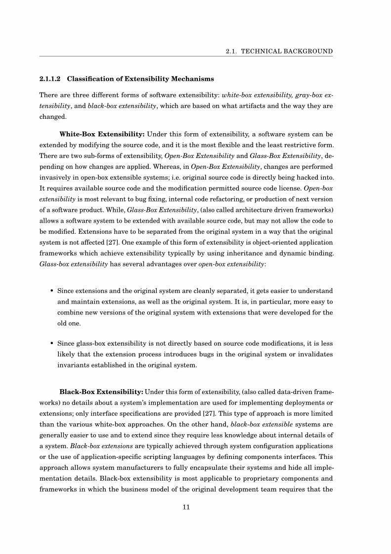
2.1.1.2 Classification of Extensibility Mechanisms
There are three different forms of software extensibility: white-box extensibility, gray-box ex-
tensibility, and black-box extensibility, which are based on what artifacts and the way they are
changed.
White-Box Extensibility: Under this form of extensibility, a software system can be
extended by modifying the source code, and it is the most flexible and the least restrictive form.
There are two sub-forms of extensibility, Open-Box Extensibility and Glass-Box Extensibility, de-
pending on how changes are applied. Whereas, in Open-Box Extensibility, changes are performed
invasively in open-box extensible systems; i.e. original source code is directly being hacked into.
It requires available source code and the modification permitted source code license. Open-box
extensibility is most relevant to bug fixing, internal code refactoring, or production of next version
of a software product. While, Glass-Box Extensibility, (also called architecture driven frameworks)
allows a software system to be extended with available source code, but may not allow the code to
be modified. Extensions have to be separated from the original system in a way that the original
system is not affected [27]. One example of this form of extensibility is object-oriented application
frameworks which achieve extensibility typically by using inheritance and dynamic binding.
Glass-box extensibility has several advantages over open-box extensibility:
• Since extensions and the original system are cleanly separated, it gets easier to understand
and maintain extensions, as well as the original system. It is, in particular, more easy to
combine new versions of the original system with extensions that were developed for the
old one.
• Since glass-box extensibility is not directly based on source code modifications, it is less
likely that the extension process introduces bugs in the original system or invalidates
invariants established in the original system.
Black-Box Extensibility: Under this form of extensibility, (also called data-driven frame-
works) no details about a system’s implementation are used for implementing deployments or
extensions; only interface specifications are provided [27]. This type of approach is more limited
than the various white-box approaches. On the other hand, black-box extensible systems are
generally easier to use and to extend since they require less knowledge about internal details of
a system. Black-box extensions are typically achieved through system configuration applications
or the use of application-specific scripting languages by defining components interfaces. This
approach allows system manufacturers to fully encapsulate their systems and hide all imple-
mentation details. Black-box extensibility is most applicable to proprietary components and
frameworks in which the business model of the original development team requires that the
11

CHAPTER 2. TECHNICAL BACKGROUND AND RELATED WORK
source code must not be published, but where external developers should still be given some
degree of flexibility in customizing and extending the functionality of the software.
Gray-Box Extensibility: This form of extensibility is a compromise between a pure
white-box and a pure black-box approach, which does not rely fully on the exposure of source
code. The rules for correctly extending a system can be described in form of reuse contracts [28].
Programmers could be given the system’s specialization interface which lists all available abstrac-
tions for refinement and specifications on how extensions should be developed [? ]. Technically,
only the original binary is required for developing extensions (assuming that the binary contains
all relevant meta-data and the development platform supports late binding).
2.1.1.3 How to apply Extensibility ?
In practice, extensibility is often either achieved by relying on design patterns or by applying
meta-programming. For design pattern-based approaches it is necessary to plan extensibility
ahead and the design should be loosely coupled which means low inter-dependency between the
modules. Coupling (in software engineering) in simple words, is how much one component knows
about the inner workings or inner elements of another one, i.e. how much knowledge it has of the
other component. Loose coupling is a method of interconnecting the components in a system so
that those components, depend on each other to the least extent practically possible. While, tight
coupling is where components are so tied to one another, that developer cannot possibly change
the one without changing the other [29].
In this StackOverflow question there is an answer that gives a funny but quite correct and
clear description of what coupling is:
"iPods are a good example of tight coupling: once the battery dies you might as well
buy a new iPod because the battery is soldered fixed and won’t come loose, thus making
replacing very expensive. A loosely coupled player would allow effortlessly changing
the battery. The same goes for software development."
— Konrad Rudolph
Components in a loosely coupled system can be replaced with alternative implementations
that provide the same services. Components in a loosely coupled system are less constrained to
the same platform, language, operating system, or build environment.
Head First Design Patterns book [29] frequently emphasizes the importance of loose
coupling. This loose coupling is achieved by principles such as "program to an interface, not an
implementation" and "encapsulate what varies". Subsequently, design patterns are applied to
implement loosely coupled system that is easy to extend in the future.
12

2.1. TECHNICAL BACKGROUND
As opposed to design patterns, meta-programming technology provides ways to extend
systems without necessarily planning extensibility ahead. Meta-programming is a programming
technique in which computer programs have the ability to treat programs as their data, such as
Lisp, Prolog, SNOBOL, and Rebol. It means that a program can be designed to read, generate,
analyze or transform other programs, and even modify itself while running. In some cases, this
allows programmers to minimize the number of lines of code to express a solution, and thus
reducing the development time. It also allows programs greater flexibility to efficiently handle
new situations without recompilation.
2.1.2 Design Patterns
In software engineering, the functional and nonfunctional requirements are taken into considera-
tion during the design phase. During designing of the application, some unforeseen problems
might arise. As the designer solves these problems, he might come across more problems. When
the solutions for these problems are closely analyzed, lot of similarities can be found and these
existing solutions can be adopted to satisfy new requirements with or without minor changes
to the existing solutions. In such a situation, the designer can use a solution that is already
proved to be a good solution, which can foresee the possible problems and take actions to avoid
such situation. That solution which is used again and again forms a particular pattern and the
solution for these recurring problems are called as design pattern.
Software design pattern is a general repeatable solution to a commonly occurring problem
in software design. It provides a description and guideline to solve a problem that can be used
in multiple different situations. Because development speed is increased when using a proven
prototype, developers, using design pattern templates, can improve coding efficiency and final
product readability.
The famous Gang of Four (GoF) by Gamma et al. [7] is the most popular book of design
patterns among practitioners. The GoF defined 23 patterns, and was published in 1994. Since
then, the book has been used countless times as a reference for studies on design patterns due to
the roots of the definition such as:
• Modeling of design patterns in UML models1 by Mak et al. [30] which present the structural
properties of design patterns which reveal the true abstract nature of pattern structures.
• Visual specification via three-model presentation of patterns by Lauder and Kent [31]
separates the specification of patterns into three models (role, type, and class). The first
model (the role-model) is the most abstract and depicts only the essential spirit of the
pattern, excluding inessential application-domain-specific details. The second model (the
1Unified Modeling Language http://www.uml.org/
13

CHAPTER 2. TECHNICAL BACKGROUND AND RELATED WORK
type-model) constrains the role-model with abstract state and operation interfaces forming
a (usually domain-specific) refinement of the pattern. The final model (the class-model)
realizes the type-model, thus deploying the underlying pattern in terms of concrete classes.
always go back to GoF definitions.
The documentation for a design pattern describes the context in which the pattern is used,
the forces within the context that the pattern seeks to resolve, and the suggested solution. There
is no single and standard format for documenting design patterns. One example of a commonly
used documentation format is the one used in GoF book of design patterns by Gamma et al. [7].
It contains the following sections:
• Pattern Name and Classification: A descriptive and unique name that helps in identi-
fying and referring to the pattern.
• Intent: A description of the goal behind the pattern and the reason for using it.
• Also Known As: Other names for the pattern.
• Motivation (Forces): A scenario consisting of a problem and a context in which this
pattern can be used.
• Applicability: Situations in which this pattern is usable, the context for the pattern.
• Structure: A graphical representation of the pattern. Class diagrams and Interaction
diagrams may be used for this purpose.
• Participants: A listing of the classes and objects used in the pattern and their roles in the
design.
• Collaboration: A description of how classes and objects used in the pattern interact with
each other.
• Consequences: A description of the results, side effects, and trade offs caused by using
the pattern.
• Implementation: A description of an implementation of the pattern; the solution part of
the pattern.
• Sample Code: An illustration of how the pattern can be used in a programming language.
• Known Uses: Examples of real usages of the pattern.
• Related Patterns: Other patterns that have some relationship with the pattern; discussion
of the differences between the pattern and similar patterns.
14

2.1. TECHNICAL BACKGROUND
The most interesting sections are the Structure, Participants, and Collaboration. Design motif
is a prototypical micro-architecture that developers copy and adapt to their particular designs
to solve the recurrent problem described by the design pattern. A micro-architecture is a set of
program constituents (e.g., classes, methods...) and their relationships. Developers use the design
pattern by introducing in their designs this prototypical micro-architecture, which means that
micro-architectures in their designs will have structure and organization similar to the chosen
design motif.
The 23 GoF patterns are generally considered the foundation for all other patterns. They
are categorized in three groups: Creational patterns, Structural patterns, and Behavioral patterns.
• Creational patterns are used to create objects for a suitable class. Generally when
instances of several different classes are available. They are particularly useful when
developers are taking advantage of polymorphism and need to choose between different
classes at runtime rather than compile time. Creational patterns allow objects to be created
in a system without having to identify a specific class type in the code, so developers do
not have to write large, complex code to instantiate an object. It does this by having the
subclass of the class create the objects. However, this can limit the type or number of objects
that can be created within a system [7]. Table 2.1 shows five creational patterns of GoF
Design Patterns.
Table 2.1: Creational patterns
Name DescriptionAbstract Factory Creates an instance of several families of classes. Provide an interface for
creating families of related or dependent objects without specifying theirconcrete classes.
Builder Separates object construction from its representation. Separate the con-struction of a complex object from its representation so that the sameconstruction processes can create different representations.
Factory Method Creates an instance of several derived classes. Define an interface forcreating an object, but let subclasses decide which class to instantiate.Factory Method lets a class defer instantiation to subclasses.
Prototype A fully initialized instance to be copied or cloned. Specify the kinds ofobjects to create using a prototypical instance, and create new objects bycopying this prototype.
Singleton A class of which only a single instance can exist. Ensure a class only hasone instance, and provide a global point of access to it.
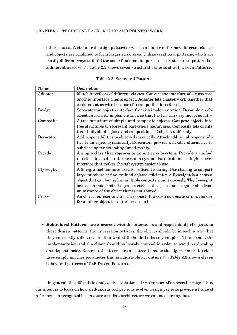
• Structural Patterns are concerned with how classes and objects can be composed, to
form larger structures and simplify the structure by identifying the relationships. These
patterns focus on, how the classes inherit from each other and how they are composed from
15
CHAPTER 2. TECHNICAL BACKGROUND AND RELATED WORK
other classes. A structural design pattern serves as a blueprint for how different classes
and objects are combined to form larger structures. Unlike creational patterns, which are
mostly different ways to fulfill the same fundamental purpose, each structural pattern has
a different purpose [7]. Table 2.2 shows seven structural patterns of GoF Design Patterns.
Table 2.2: Structural Patterns
Name DescriptionAdapter Match interfaces of different classes. Convert the interface of a class into
another interface clients expect. Adapter lets classes work together thatcould not otherwise because of incompatible interfaces.
Bridge Separates an object’s interface from its implementation. Decouple an ab-straction from its implementation so that the two can vary independently.
Composite A tree structure of simple and composite objects. Compose objects intotree structures to represent part-whole hierarchies. Composite lets clientstreat individual objects and compositions of objects uniformly.
Decorator Add responsibilities to objects dynamically. Attach additional responsibili-ties to an object dynamically. Decorators provide a flexible alternative tosubclassing for extending functionality.
Facade A single class that represents an entire subsystem. Provide a unifiedinterface to a set of interfaces in a system. Facade defines a higher-levelinterface that makes the subsystem easier to use.
Flyweight A fine-grained instance used for efficient sharing. Use sharing to supportlarge numbers of fine-grained objects efficiently. A flyweight is a sharedobject that can be used in multiple contexts simultaneously. The flyweightacts as an independent object in each context, it is indistinguishable froman instance of the object that is not shared.
Proxy An object representing another object. Provide a surrogate or placeholderfor another object to control access to it.
• Behavioral Patterns are concerned with the interaction and responsibility of objects. In
these design patterns, the interaction between the objects should be in such a way that
they can easily talk to each other and still should be loosely coupled. That means the
implementation and the client should be loosely coupled in order to avoid hard coding
and dependencies. Behavioral patterns are also used to make the algorithm that a class
uses simply another parameter that is adjustable at runtime [7]. Table 2.3 shows eleven
behavioral patterns of GoF Design Patterns.
In general, it is difficult to analyze the evolution of the structure of an overall design. Thus,
our intent is to focus on how well-understood patterns evolve. Design patterns provide a frame of
reference —a recognizable structure or micro-architecture we can measure against.
16

2.1. TECHNICAL BACKGROUND
Table 2.3: Behavioral Patterns
Name DescriptionChain of Resp. A way of passing a request between a chain of objects. Avoid coupling the
sender of a request to its receiver by giving more than one object a chanceto handle the request. Chain the receiving objects and pass the requestalong the chain until an object handles it.
Command Encapsulate a command request as an object, thereby letting developersparameterize clients with different requests, queue or log requests, andsupport undoable operations.
Interpreter A way to include language elements in a program. Given a language,define a representation for its grammar along with an interpreter thatuses the representation to interpret sentences in the language.
Iterator Sequentially access the elements of a collection. Provide a way to accessthe elements of an aggregate object sequentially without exposing itsunderlying representation.
Mediator Defines simplified communication between classes. Define an object thatencapsulates how a set of objects interact. Mediator promotes loose cou-pling by keeping objects from referring to each other explicitly, and it letsdeveloper varies their interaction independently.
Memento Capture and restore an object’s internal state. Without violating encapsu-lation, capture and externalize an object’s internal state so that the objectcan be restored to this state later.
Observer A way of notifying change to a number of classes. Define a one-to-manydependency between objects so that when one object changes state, all itsdependents are notified and updated automatically.
State Alter an object’s behavior when its state changes. Allow an object to alterits behavior when its internal state changes. The object will appear tochange its class.
Strategy Encapsulates an algorithm inside a class. Define a family of algorithms,encapsulate each one, and make them interchangeable. Strategy lets thealgorithm vary independently from clients that use it.
Template Defer the exact steps of an algorithm to a subclass. Define the skeleton ofan algorithm in an operation, deferring some steps to subclasses. TemplateMethod lets subclasses redefine certain steps of an algorithm withoutchanging the algorithm’s structure.
Visitor Defines a new operation to a class without change. Represent an operationto be performed on the elements of an object structure. Visitor lets devel-opers define a new operation without changing the classes of the elementson which it operates.
2.1.3 Software Design Decay
GoF design patterns are popular among both researchers and practitioners, in the sense that
software can be largely comprised of pattern instances. Consequently, the same pattern can have
both a positive and a negative effect on the quality of a software product. However, there are
17

CHAPTER 2. TECHNICAL BACKGROUND AND RELATED WORK
concerns regarding the efficacy with which software engineers maintain pattern instances, which
tend to decay over the software lifetime if no special emphasis is placed on them.
As the focus of this thesis lies on design pattern violations and their evaluation then resolve
the detected violations as a key step in extending software systems. This thesis reviews the early
work of Izurieta and Bieman [32] on type of design pattern violations called decay. Decay can
involve the design patterns used to structure a system where classes that participate in design
pattern realizations accumulate non pattern related code. Izurieta and Bieman investigated the
evolution of design pattern implementations to comprehend how patterns decay and examined
the extent to which software designs actually decay by studying the aging of design patterns
in three successful object-oriented systems that include the entire code base of JRefactory, and
added two additional open source systems —ArgoUML and eXist. The results indicate that
pattern grime (non-pattern-related code) that builds up around design patterns is mostly due to
increases in coupling and it is the main factor for the decay of software design patterns. Pattern
grime is defined as "degradation of the instance due to buildup of unrelated artifacts e.g., methods
and attributes in pattern instances" as a type of decay and divided the grime in to three categories
—class, modular and organizational grime, and it has been pointed out as one recurrent reason
for the decay of GoF pattern instances.
Consequently, Izurieta in his doctoral dissertation [33] studied the accumulation of pattern
decay and recognized another type of design decay called pattern rot. Furthermore, he noticed
that this form of violations destroys structural integrity of design patterns. Pattern rot which is
either a slow deterioration of software performance over time or its diminishing responsiveness
that will eventually lead to software becoming faulty, unusable and in need of upgrade. Two
distinct categories of design pattern decay were identified:
• Design Pattern Grime: accumulation of unnecessary or unrelated software artifacts
within the classes of a design pattern instance.
• Design Pattern Rot: violations of the structure or architecture of a design pattern.
Design pattern realizations can become a rot, when modifications of source code disrupt the
structural or functional integrity of a design pattern. Design pattern rot due to failure to meet
their responsibilities during pattern implementations, and thus represents a fault. In contrast
with grime buildup does not break the structural integrity of a pattern but can reduce system
testability and adaptability [34].
Furthermore, Naouel Moha et al. [35] defined a taxonomy of potential design pattern
defects and conducted an empirical study to investigate their existence. The authors defined
design pattern defects as errors occurring in the design of the software which come from the
18

2.2. RELATED WORK
absence or the bad use of design patterns. The taxonomy includes the following four types of
defects: An approximative or deformed design pattern is a design pattern that has not been well
conforming with GoF [7] definition but that is not erroneous. A Distorted or degraded design
pattern is a distorted form of a design motif which is harmful for the quality of the code. A
Missing design pattern is when a design is missing a needed design pattern. According to GoF
[7], missing patterns generates poor design. Excess design pattern is the over use of design
patterns in a software design. Later on, Izurieta cooperated with other researchers to obtain
better comprehensions of patterns decay. Afterwards, Dale and Izurieta [36] proposed a study on
impacts of design patterns decay on quality of project.
2.2 Related Work
Inside the source code, a lot of information is hidden that we can extract using multiple tech-
niques like static analysis, dynamic analysis, similarity scoring and parsing etc. Lately, design
pattern detection has attracted the effort of the software engineering community and has led
to the development of several tools to detect design patterns such as Tsantalis DPD2, Pinot3,
Web of Patterns4, ePAD5, MARPLE-DPD 6, and DP-CoRe7. Nevertheless, to the best of our knowl-
edge, there has been little work done in developing automated tools to identify design pattern
violations and determine whether the pattern characteristics are met or not, based on the GoF
definitions by Gamma et al. [7], where each design pattern is specified by certain characteristics
should be considered during development. Consequently, a new approach to assess the design of
current software project, and provide recommendations as solutions for the detected violations,
is an essential step for extensibility of the software applications in order to provide a valuable
information about current software version before starting re-engineering process to extend its
functionalities.
2.2.1 Design Pattern Detection Tools
The detection of design patterns in a software system, which is an important task in the re-
engineering process, exploiting only UML diagrams and designer’s experience, is very difficult in
the absence of automated assistance tools.
2TsantalisDPD https://users.encs.concordia.ca/~nikolaos/3Pinot http://web.cs.ucdavis.edu/~shini/research/pinot/4Web of Patterns http://www-ist.massey.ac.nz/wop/5ePAD http://www.sesa.dmi.unisa.it/ePAD/6MARPLE http://essere.disco.unimib.it/wiki/marple7DP-CoRe https://github.com/AuthEceSoftEng/DP-CORE/
19

CHAPTER 2. TECHNICAL BACKGROUND AND RELATED WORK
2.2.1.1 Tsantalis Design Pattern Detection (Tsantalis DPD)
Design pattern detection using similarity scoring [37] by Tsantalis et al. (Tsantalis DPD) proposed
a fully automated pattern detection process by extracting the actual instances in a system for
the patterns that the user is interested in. Within the study authors employ an algorithm for
measuring similarity scoring between graph vertices as an instrument of pattern detection. The
main contribution of the approach is the use of a similarity algorithm, which has the inherent
advantage of also detecting patterns that appear in a form that deviates from their standard
representation.
In Tsantalis DPD proposed methodology, both the system under study as well as the design
pattern to be detected are described in terms of graphs. In particular, the approach employs a
set of matrices representing all important aspects of their static structure. For the detection of
patterns, the authors employ a graph similarity algorithm [38], which takes as input both the
system and the pattern graph and calculates similarity scores between their vertices.
Tsantalis DPD tool has been evaluated on JHotDraw [39], JRefactory [40], and JUnit
[41], which are open-source projects extensively and systematically employing design patterns.
The results have been validated against internal and external documentation of those systems.
For the design patterns that have been examined, the number of false negatives was limited
while false positives have not been found. Consequently, evaluation on three open-source projects
demonstrated the accuracy and the efficiency of the proposed method.
However, the scores received from measurements are not presented in paper, neither
are they displayed to the user of the tool. Reason for this lies in fact, that the purpose of tool
is to detect pattern instances present in the source code, not to evaluate correctness of their
implementation.
2.2.1.2 Pattern Inference and recOvery Tool (Pinot Tool)
In reverse engineering of design patterns from Java source code research [42], Nija Shi and Ron
Olsson present a fully automated pattern detection approach based on reclassification of the
GoF patterns by their pattern intent. The authors argue that the GoF pattern catalog classifies
design patterns in the forward engineering sense; their reclassification is better suited for reverse
engineering. They implemented a fully automated pattern detection tool, called PINOT. The
current implementation of PINOT detects all the GoF patterns that have concrete definitions
driven by code structure or system behavior.
PINOT detects many uses of GoF patterns in recent versions of Java open source code.
Reports of detected pattern instances are available for: Java AWT 1.3, JHotDraw 6.0b1, Java
Swing 1.4, java.io 1.4.2, java.net 1.4.2, javac 1.4.2, Apache Ant 1.6.2, ArgoUML 0.18.1.
20

2.2. RELATED WORK
PINOT tool combines both structural and behavioral analysis. It extracts information from
the Abstract Syntax Tree (AST) of the source code, and detects patterns using structural and
behavioral (data flow) template matching.
2.2.1.3 Eclipse plug-in for design Pattern Analysis and Detection (ePAD Tool)
Lucia et al. [43] present ePAD, an eclipse plug-in for recovering design pattern instances from
object-oriented source code. The tool is able to recover design pattern instances through a
structural analysis performed on a data model extracted from source code, and a behavioral
analysis performed through the instrumentation and the monitoring of the software system.
In particular, ePAD detects design pattern instances from object oriented source code through
a static analysis, to extract the instances according to their structural properties [44], and a
subsequent dynamic analysis, to verify the runtime behavior of the detected instances [45].
ePAD is fully customizable since it allows engineers to configure the definition of the
patterns structure and their behavior and the layout to be used for visualizing their instances. In
order to highlight the main features of ePAD, authors present an example of usage of the tool on
JHotDraw 5.1 and discuss the obtained results. In addition ePAD provides users with a simple
GUI allowing to select the software system to be analyzed and generate a list of the recovered
design pattern instances, whereas tools like PINOT [42] works at command line.
2.2.1.4 MARPLE for Design Pattern Detection (MARPLE-DPD)
Several tools also use machine learning methods. Arcelli and Christina developed MARPLE
(Metrics and Architecture Recognition PLug-in for Eclipse) [46–48], an Eclipse plugin that uses
neural networks to classify source code representations to behavioral patterns. The MARPLE
project focuses on the development of a complete tool for the recognition of software architectures
and of design patterns (also with the help of metrics, both common object-oriented and new ones)
inside Java programs. As far as the design pattern detection activity is concerned, the analysis
provided by the tool are static and based upon the core concept of the identification of the so-called
Design Pattern Clues, which are particular code structures and details which should give hints
about the presence of design pattern inside the code.
The authors implemented a tool called MARPLE-DPD, their approach allows the appli-
cation of machine learning techniques, leveraging a modeling of design patterns that is able
to represent pattern instances composed of a variable number of classes. They describe the
experimentation for the detection of five design patterns on 10 open source software systems,
compare the performances obtained by different learning models.
21

CHAPTER 2. TECHNICAL BACKGROUND AND RELATED WORK
2.2.1.5 A Design Pattern Detection Tool for Code Reuse (DP-CoRe Tool)
Diamantopoulos et al. [24] proposed an open-source design pattern detection tool called a Design
Pattern detection tool for COde REuse (DP-CoRe tool). DP-CoRe supports the detection of 6 GoF
patterns of all types: the creational patterns Abstract Factory and Builder, the structural pattern
Bridge, and the behavioral patterns Command, Observer and Visitor. As well, the tool offers the
ability to add custom pattern definitions by the software developer. Adding custom pattern is one
of the most important features of DP-CoRe tool.
The effectiveness of DP-CORE is assessed using two evaluation experiments. The first
experiment involves an example project including known instances of patterns, while the second
experiment involves a comparison to PINOT [42] for detecting patterns in the source code of
known Java libraries (e.g. JHotDraw 6.0b1, Java AWT 1.3, and Apache Ant 1.6.2.).
DP-CORE successfully identified all the pattern instances in the project. It is notable,
though, that the tool detected false positive instances, since 27.27% of the detected instances
are not design patterns. These false positives are due to the non-strict definition of the patterns.
False positives can be minimized by providing more precise definitions of patterns.
However, DP-CoRe depends on the latest compiler technology to enhance the detection of
patterns instances in Java applications, DP-CoRe neither evaluates the conformance of pattern
implementations towards pattern definitions nor focuses on measurement of their impact on code.
The reason is that the tool is designed to detect pattern instances present in the source code, not
to evaluate correctness of their implementation.
2.2.2 Design Pattern Assessment Tools
Design patterns have been studied from various points of view by many authors. There has been
little work done in creating an automated tool for validating instances of design patterns and
identifying violations that can be harmful to the quality of pattern instances and the overall
system.
Primarily studies targeting design pattern validation by Strasser et al. [49] focused on
design patterns scoring where each candidate pattern is given a score, based on the resemblance
with the design pattern definition. The author’s proposed approach uses the Role-Based Meta-
modeling Language (RBML) [50] in combination with PlantUML 8 specification to calculate score
of patterns conformance towards pattern definitions. The Role Based Metamodeling Language is
a visually oriented language defined in terms of a specialization of the UML metamodel that is
used to verify and specify generic or domain specific design patterns.
8PlantUML http://plantuml.sourceforge.net/
22

2.2. RELATED WORK
The Role-Based Metamodeling Language, (RBML) was developed in 2003 as a way of
expressing domain specific design patterns which can be instantiated as UML diagrams [51]. By
having a standard language to specify design patterns, a developer is constrained by a set of rules
when creating a UML diagram for a particular design pattern, resulting in better quality code.
RBML is based upon UML and uses the same syntax as UML. It consists of a number
of behavioral and structural diagrams with each one describing different parts of the design
pattern. Whereas a UML diagram has classes and interfaces, an RBML diagram has classes
(which represent classes) and classifiers (which represent interfaces and abstract classes). Within
each class and classifier, the RBML has behaviors and attributes, which represent methods and
attributes in a UML model instantiation. RBML also has generalization, association, and depen-
dency relationships between the different classifiers and classes which can also be instantiated
in UML model representations. Finally, RBML specifications can have multiplicity constraints on
attributes, behaviors, and relationships [52]. An example UML diagram and its corresponding
RBML specification are shown in Figure 2.1.
Figure 2.1: An example of a RBML diagram on the left and a UML instance on the right [1]
To compare an RBML and a UML diagram, the authors used the divide - and - conquer
algorithm developed by Kim and Shen [52]. The algorithm works as follows: first the RBML and
UML diagrams are broken up into blocks, which are defined as any two classes or classifiers
(classes and interfaces in UML) which have a relationship between them. Because there are
23

CHAPTER 2. TECHNICAL BACKGROUND AND RELATED WORK
three kinds of relationships, there are three different kinds of block types: association blocks,
generalization blocks, and dependency blocks. In the example in Figure 2.1, there is only one
RBML block (since there are only two classes). In the UML diagram, there are two blocks: one
for the Kiln - TemperatureObs relationship and one for the Kiln - PressureObs relationship.
After all the blocks have been created, the algorithm first performs local conformity checks. By
checking all the UML’s block behaviors, attributes, and multiplicities to see if they satisfy those
constrained in the RBML’s block.
The authors designed RBML-UML-Visualizer tool 9 in order to inform developers when
design patterns no longer conform to their original intended design. One of the drawbacks
mentioned by the authors is that the algorithm only permits an UML object to be matched with
an RBML model if the UML satisfies all of the RBML blocks requirements. Subsequently, some
pattern instances cannot be evaluated without providing both RBML definitions and PlantUML
specifications. If only one behavior in UML is missed deliberately, the scoring result is decreased
from 100% to be 45.83%. In order to overcome those drawbacks the validation of design pattern
instances should be done based on source code files directly without relying on RBML model or
UML diagram.
2.3 Round-trip Engineering
A software engineering area that is getting prominent in the vast field of software maintenance
and evolution is reverse engineering. One of the goals of this discipline aims at the obtainment of
views of already existing complex software systems, in order to try to understand which are its
constituent components and have a general "easy to manage" view of its architecture.
Software developers need a complete and reliable adjustment of source code and diagrams.
For the first time, software architects and developers can make use of the benefits of both worlds:
fully flexible modeling and programming. The problem of changing from design to implementation
- and back again - is solved by UML Lab [53] smoothly and reliably by using Round-Trip-
Engineering 10 that can reduce development time of implementation and maintenance and
supports the documentation and quality assurance of complex software projects.
The need for round-trip engineering arises when the same information is present in
multiple artifacts and therefore an inconsistency may occur if not all artifacts are consistently
updated to reflect a given change. For example, some piece of information was added to / changed
in only one artifact and, as a result, it became missing consistent with the other artifacts.
9Strasser et al. automated tool is free and is available to download at http://code.google.com/p/rbml-uml-visualizer/
10Round-Trip Engineering (RTE) is a functionality of software development tools that synchronizes two or morerelated software artifacts, such as, source code, models, configuration files, and even documentation
24

2.3. ROUND-TRIP ENGINEERING
Round-trip engineering is closely related to traditional software engineering disciplines:
Forward Engineering (FE) is when software developers have a model and construct code based on
the model (Transformation or function from Model to Code), Reverse Engineering (RE) is when
developers have code and construct a model that represents the code (Transformation or function
from Code to Model), and re-engineering (understanding existing software and modifying it).
Round trip engineering supports an iterative development process.After software develop-
ers have synchronized the model with revised code, developers are still free to choose the best way
to make further modifications to the code or make changes to the model. Software developers can
synchronize in either direction at any time and can repeat the cycle as many times as necessary.
The following sub-subsections demonstrate some tools which are used in round-trip engineering
process.
2.3.1 UML Lab
Through the innovative combination of modeling and programming UML Lab [53] utilizes the full
potential of model-based software development. Software development projects become simpler,
faster and more cost-efficient. The overview and flexible automation that are provided, save
valuable development time, avoid error sources and support documentation for maintenance and
care of software.
UML Lab automatically keeps UML models synchronized with their associated source
code. If any source code file is modified and saved, UML Lab immediately starts a reverse
engineering process and updates the associated UML model and all related UML diagrams. For
example, if an attribute is added to a Java class and the changes are saved in the source code, a
corresponding UML attribute is immediately added to all UML classes in any UML class diagram
that correspond to this Java class.
2.3.2 Altova UModel
The Altova UModel [54] round-trip engineering capability reads the modified code and automati-
cally updates UML diagrams accordingly. This synchronization keeps the model accurate and
relevant as code changes. Reviewing updated UML diagrams that reflect the changes to the code
can help software developer to verify his intended result or quickly identify errors.
UModel does not require any pseudo-code or special comments in the generated code to
perform successful round-tripping. This leaves the source code free of artifacts that can make
it harder to understand or edit directly. UModel round trip engineering supports an iterative
development process. After developer has synchronized his model with revised code, he is still
free to choose the best way to make further modifications to the code or make changes to software
25

CHAPTER 2. TECHNICAL BACKGROUND AND RELATED WORK
model. Software developer can synchronize in either direction at any time and he can repeat the
cycle as many times as necessary.
2.3.3 IBM Rational Software Architect
IBM Rational Software Architect [55] is a design and development tool that integrates UML
modeling and round-trip engineering. Rational Software Architect provides the tools to generate
source code from UML models as well as UML models from source code, which facilitates round-
trip engineering. Rational Software Architect shortens development times by generating stubs of
source code automatically and brings designs up to date quickly by converting changes in the
source code into UML model elements automatically.
A large number of software artifacts and different versions of these software artifacts are
generated during a round-trip software development process. It is thus critical to have these
software artifacts and their versions maintained all the time.
2.3.4 UML Round Trip Engineering Tools Comparison
Table 2.4 shows a comparison between the most three popular tools that support round trip
engineering.
Table 2.4: UML Round Trip Engineering Tools
UML Round Trip Engineering ToolsUML tool name Forward engi-
neeringReverse engi-neering
Round tripengineering
Tool collaboration
UML Lab Java Java YES Eclipse, Top-CASED, RationalSoftware Archi-tect
Altova UModel C#,JAVA,Visualbasic, XSD
C#,JAVA,Visualbasic, XSD
YES Eclipse, Visualstudio
IBM Rational Soft-ware Architect
Java Java YES Eclipse
IBM Rational Software Architect and UML-Lab are Commercial tools and free for Academic
use, while Altova UModel is Commercial tool only.
In our proposed approach (next chapter), UML Lab Modeling is used to get UML models
synchronized with their associated source code of the project under study. The reasons behind
selection UML Lab because it is the first Modeling IDE to seamlessly combine modeling and
programming with an intuitive UML diagram editor and get a nice overview via UML within
26

2.3. ROUND-TRIP ENGINEERING
Figure 2.2: UML Lab Modeling IDE
seconds. Figure 2.2 shows a screen shot illustrating the UML Lab tool and how UML models is
synchronized with their associated source code, and figure 2.3 shows UML models as XML file
that will be parsed to find the pertinent information related to detection design patterns. As it is
explained in the following subsection 2.3.5
2.3.5 Analysis of UML Design using XML Parsers
A parser can read the XML document components via Application Programming Interfaces (APIs)
in two approaches (stream-based approach and tree-based approach). For stream-based approach
(also known as event-based parser), it reads through the document and signal the application
every time a new component appears. As for tree-based approach, it reads the entire document
into a memory resident collection of object as a representation of original document in tree
structure [56, 57]. As a result, tree-based approach is not suitable for large-scale XML data
because it can easily run out of memory[58].
Simple API for XML (SAX), StAX and XMLPull are stream-based approach API while
Document Object Model (DOM), JDOM, ElectricXML, DOM4j are categorized as tree-based API.
27

CHAPTER 2. TECHNICAL BACKGROUND AND RELATED WORK
Figure 2.3: XML file representing the UML design
Most of the major XML parsers support both SAX and DOM. A brief comparison of the most
popular XML parser’s APIs, with respect to their characteristics are depicted in Table 2.5
Table 2.5: Comparison on XML Parser’s APIs
APIs Advantages DisadvantagesDOM Easy navigation,
Entire tree loaded into memory,Random access to XML document,Rich set of APIs.
XML document must be parsed at onetime,It is expensive to load entire tree intomemory.
SAX Entire document not loaded intomemory which resulting in low mem-ory consumption,Allows registration of multiple Con-tent Handlers.
No built-in document navigation sup-port,No random access to XML document,No support for modifying XML in place,No support for namespace scoping.
2.3.5.1 Extensible Markup Language (XML)
XML is a simple text based language which was designed to store and transport data in plain
text format. It stands for Extensible Markup Language. The advantages that XML provides:
Technology agnostic - Being plain text, XML is technology independent. It can be used by any
technology for data storage and transmission purpose. Human readable - XML uses simple text
28

2.3. ROUND-TRIP ENGINEERING
format. It is human readable and understandable. Extensible - in XML, custom tags can be
created and used very easily. Allow Validation - XML structure can be validated easily.
2.3.5.2 XML Parser
XML Parser provides way how to access or modify data present in an XML document. Java
provides multiple options to parse XML document. Following are two types of parsers which are
commonly used to parse XML documents.
• Document Object Model (DOM)11 is an object-oriented representation of XML or HTML
document. A DOM is a standard tree structure, where each node contains one of the
components from an XML structure. The two most common types of nodes are element
nodes and text nodes. Using DOM functions lets developers create nodes, remove nodes,
change their contents, and traverse the node hierarchy.
The Document Object Model is an official recommendation of the World Wide Web Consor-
tium (W3C). It defines an interface that enables programs to access and update the style,
structure,and contents of XML documents. XML parsers that support the DOM implement
that interface.
When the XML document is parsed with a DOM parser, software developer gets back a
tree structure that contains all of the elements of XML document. The DOM provides a
variety of functions that developers can use to examine the contents and structure of the
document.
The DOM is a common interface for manipulating document structures. One of its design
goals is that Java code written for one DOM-compliant parser should run on any other
DOM-compliant parser without changes.
• Java SAX Parser (SAX)12, the Simple API for XML, is an event-based parser for xml
documents.Unlike a DOM parser, a SAX parser creates no parse tree. SAX is a streaming
interface for XML, which means that applications using SAX receive event notifications
about the XML document being processed an element, and attribute, at a time in sequential
order starting at the top of the document, and ending with the closing of the ROOT element.
– Reads an XML document from top to bottom, recognizing the tokens that make up a
well-formed XML document
– Tokens are processed in the same order that they appear in the document
– Reports the application program the nature of tokens that the parser has encountered
as they occur11Document Object Model (DOM) https://docs.oracle.com/javase/tutorial/jaxp/dom/readingXML.html12Java SAX Parser (SAX) https://docs.oracle.com/javase/tutorial/jaxp/sax/parsing.html
29

CHAPTER 2. TECHNICAL BACKGROUND AND RELATED WORK
– The application program provides an "event" handler that must be registered with
the parser
– As the tokens are identified, callback methods in the handler are invoked with the
relevant information
Disadvantages of SAX:
– We have no random access to an XML document since it is processed in a forward-only
manner
– If software developers need to keep track of data the parser has seen or change the
order of items, they must write the code and store the data on their own.
In chapter 4, "Implementation, Practical Experiment and Results", we used Document Object
Model (DOM) parser in processing the inputs of our second experiment.
2.4 Natural Language Processing Toolkits
Natural language processing (NLP) is a field of computer science, artificial intelligence, and com-
putational linguistics concerned with the interactions between computers and human (natural)
languages. It includes word and sentence tokenization, text classification and sentiment analysis,
spelling correction, information extraction, parsing, meaning extraction, and question answering.
NLP algorithms are typically based on machine learning algorithms. Instead of hand-
coding large sets of rules, NLP can rely on machine learning to automatically learn these rules
by analyzing a set of examples (i.e. a large corpus, like a book, down to a collection of sentences),
and making a statical inference. In general, the more data analyzed, the more accurate the model
will be.
Many researchers proposed methods for analyzing software requirements specified using a
natural language. The aim of their studies was to analyze requirements which are specified using
a natural language (NL). In addition, there are many open source Natural Language Processing
(NLP) libraries.
Reynaldo Giganto, in his paper [59], uses controlled NL text of requirements to generate
class models. His paper describes some initial results arising out of parsing the text for ambiguity.
The paper introduces a research plan of the author to integrate requirement validation with
RAVEN project.
30

2.4. NATURAL LANGUAGE PROCESSING TOOLKITS
Deva Kumar, et al. [60], created an automated tool (UMGAR) to generate UML’s analysis
and design models from natural language text. They have used Stanford parser [61, 62], Word
Net 2.1 [63] and Java RAP13 to accomplish this task.
Sascha, et al. [64], proposed a round trip engineering process by creating SPIDER tool. The
paper addressed the concerns about errors at requirement level being propagated to design and
coding stages. The behavioral properties shown from the NL text are utilized to give developer a
UML model.
Priya More, et al. [65], have developed a from NL text UML Diagrams. They have developed
a tool called RAPID for analyzing the requirement specifications. The software used for completing
the task is OpenNLP, RAPID Stemming algorithm, WordNet.
2.4.1 Stanford CoreNLP - Natural language software Toolkit
Stanford CoreNLP [66] provides a set of human language technology tools. It can give the base
forms of words, their parts of speech, whether they are names of companies, people, etc., normalize
dates, times, and numeric quantities, mark up the structure of sentences in terms of phrases
and syntactic dependencies, indicate which noun phrases refer to the same entities, indicate
sentiment, extract particular or open-class relations between entity mentions, get the quotes
people said, etc. as it is shown in Figure 2.4
Stanford CoreNLP’s goal is to make it very easy to apply a bunch of linguistic analysis
tools to a piece of text. A tool pipeline can be run on a piece of plain text with just two lines of
code. CoreNLP is designed to be highly flexible and extensible. With a single option software
developer can change which tools should be enabled and disabled. Stanford CoreNLP integrates
many of Stanford’s NLP tools, including the part-of-speech (POS) tagger, the named entity
recognizer (NER), the parser, the coreference resolution system, sentiment analysis, bootstrapped
pattern learning, and the open information extraction tools. Moreover, an annotator pipeline can
include additional custom or third-party annotators. CoreNLP’s analyses provide the foundational
building blocks for higher-level and domain-specific text understanding applications.
2.4.2 NLTK - Natural Language Processing Toolkit
NLTK [67] is a leading platform for building Python programs to work with human language
data. It provides easy-to-use interfaces to over 50 corpora and lexical resources such as WordNet,
along with a suite of text processing libraries for classification, tokenization, stemming, tagging,
parsing, and semantic reasoning, and wrappers for industrial-strength NLP libraries.
13RAP: Remote Application Platform http://www.eclipse.org/rap/
31

CHAPTER 2. TECHNICAL BACKGROUND AND RELATED WORK
Figure 2.4: Some examples of Stanford CoreNLP
NLTK is intended to support research and teaching in NLP or closely related areas,
including empirical linguistics, cognitive science, artificial intelligence, information retrieval, and
machine learning. NLTK has been used successfully as a teaching tool, as an individual study
tool, and as a platform for prototyping and building research systems. There are 32 universities
in the US and 25 countries using NLTK in their courses.
2.4.3 Natural Language Processing In Software Engineering
Software Development Life Cycle (SDLC) consists of set phases which provide guidelines to
develop software. NLP can be applied to every phase within Software Development Life Cycle
[68]. It is specifically more useful when the artifacts of phase or activity are plain text. Plain
text can be provided as input to natural language processing tasks. Basically all the activities in
which the humans interpret the document there is scope of textual generation [69].
The requirement document is authored by the system analyst after understanding the
requirements given by stakeholders. Software Requirement Specification (SRS) is a textual
32

2.4. NATURAL LANGUAGE PROCESSING TOOLKITS
written agreement signed between the company and the stakeholders. Use cases describe the
interaction of system to be developed with various actors [68]. By having a textual format of SRS,
it is possible to automate using NLP tools and techniques to extract the relationships between
system entities directly from SRS. The extracted relationships could be helpful to conform the
detection of design violations according business logic for refactoring or discard them.
33


CH
AP
TE
R
3PROPOSED APPROACH
Design patterns are often mentioned as double-edged sword, applying the right pattern
can produce good-quality software while applying a wrong one (anti-pattern) makes
it disastrous and creates many problems for system design. However, implemented in
the right place, at the right time, it can be system saviour [20]. Therefore, the usage of design
patterns needs to be better supported and automated by approaches that would automatically
provide information about the applied design pattern aspects. The detection of violations in
early stages of evolution and based on their severity and overall pattern performance decide to
keep, refactor or discard them. This is why the thesis builds an automated tool that focuses on
identifying violations of design pattern implementations against design definitions at first. The
second focuses on measuring their impact on code and a possible scoring for discovered violations.
Such approach might save time and resources during software maintenance and refactoring.
In this chapter, we describe the phases of the proposed approach, as shown in Figure 3.1.
The first phase describes how DP-CoRe is integrated as part of DPVIA, and how design pattern
detection approach, by Diamantopoulos et al. [24], is working. The design pattern detection phase
receives two inputs: the examined repository projects and the pattern abstraction & connections
rules files that could be modified by the software developer. The output is a list of detected pattern
instances, discussed in Section 3.1. Thereafter, the tool calculates the conformance scores of the
detected design pattern instances implementation versus their definitions in order to produce a
preliminary identification of violations in the second phase, discussed in Section 3.2. The last
phase verifies the detected violations by examining relationships between entities participated
in those violations according to system requirement specifications (SRS) document in format of
IEEE template. This phase is implemented with help of the Stanford CoreNLP Natural Language
35

CHAPTER 3. PROPOSED APPROACH
Processing Toolkit [70]. Consequently, the detected violation is considered a clear violation only
if the relationship between violation entities is found in software business logic, discussed in
Section 3.3. Finally, the proposed DPVIA tool reports the conformance scores of the detected
pattern instances, and suggests refactoring recommendations for the software developer to modify
design pattern candidates and resolve their violations with minimum impact.
Figure 3.1: Phases of usage of the DPVIA tool
3.1 Design Patterns Detection
3.1.1 Representing Objects and Relationships
In order to detect design pattern instances from source code file in project under study, design
patterns must have specific properties for their representations in project source code. We used
the updated representation of design pattern by Diamantopoulos et al. [24] where the authors
proposed two concepts for design pattern representation: the abstraction of each class (class type)
and the relationships between two classes.
At first, representation of the abstraction class types are shown in Table 3.1, The type
Normal refers to a simple class/non-abstracted class, while the type Abstract corresponds to the
known Java abstract classes and Interface correspond to the known Java interface classes. In
addition, the type Abstracted refers to class that might either one of types Abstract or Interface,
while the type Any denotes any of the above abstraction types. Secondly, representation of the
directional relationships between two classes was defined by 6 types of connections that are
summarized in Table 3.2, including their description, and the corresponding UML relation for
each connection. The connections cover all possible relations that can exist in a source code project.
36

3.1. DESIGN PATTERNS DETECTION
Table 3.1: Representing Design Pattern Abstraction Types
Abstraction Type DescriptionNormal a non-abstracted class (e.g. class A { ... })Abstract a Java abstract class (e.g. abstract class A { ... })Interface a Java interface (e.g. interface class A { ... })Abstracted an abstract class or an interface classAny any of the above class types
The relation of dependency is handled by connections calls/uses and association is handled by
connection references, while compositions and aggregations correspond to the creates and has
connections. Inheritance and realization relations are handled by the inherits connection.
Table 3.2: Representing Design Pattern Directional Relationships Between Classes
ConnectionType
Description UML Relation
A calls B a method of class A calls a method of class B DependencyA creates B class A creates an object of type class B CompositionA uses B a method of class A returns an object of type B DependencyA has B class A has one or more objects of type B AggregationA references B a method of class A has as parameter an object of type B AssociationA inherits B class A inherits class B or class A realizes/implement in-
terface BInheritance /Realization
3.1.2 Representing Design Patterns
Upon having the representation of source code classes and relationships are represented in our
approach, software developer can illustrate how well known (or custom) design patterns can be
represented in the software system. For any pattern, developer must define the abstraction of
design pattern member classes and the relationships among them.
In this subsection, we illustrate how seven design patterns are defined according to the GoF
by Gamma et al. [7]. We selected at least two patterns for all categories: the creational patterns
Simple Factory Pattern and Factory Method, the structural patterns Adapter and Decorator, and
the behavioral patterns Observer, State and Strategy.
The purpose of the Simple Factory pattern is "using a factory class which has a
method that returns different types of objects based on given input to create an instance of several
families of classes". By definition, a Simple Factory pattern has to include instances of Creator
(Simple Factory), Concrete Creator (Concrete Factory), Abstract Product, and Concrete Product.
Using the representation of subsection 3.1.1, we define the 4 members of the pattern and their
connections in Figure 3.2. One instance of a Simple Factory pattern source code is reversed
37

CHAPTER 3. PROPOSED APPROACH
SimpleFactoryA Normal Concrete ProductB Abstract ProductC Normal Concrete CreatorD Normal CreatorEnd_MembersA inherits BD has CD uses BC creates AEnd_Connections
Figure 3.2: Simple Factory pattern representation in source code
Figure 3.3: Simple Factory pattern UML instance class diagram
to UML by UML Lab ( Figure 3.3 ) in order ensure the validity of previous Simple Factory
pattern representation. For each pattern member, A, B, C,and D, we can see its abstraction
type and its connections. The CheesePizza, ClamPizza, PepperoniPizza, and VeggiePizza classes
are considered as (A) Normal Concrete Product member. Class Pizza refers to (B) Abstract
Product member, while SimplePizzaFacrtory represents (C) Normal Concrete Creator member,
and PizzaStore class represents (D) Normal Creator member.
The purpose of the Factory Method pattern is to "create an instance of several de-
rived classes. Define an interface for creating an object, but let subclasses decide which class to
instantiate. Factory Method lets a class defer instantiation to subclasses". By definition, a Factory
Method pattern has to include instances of Creator (Factory Method), Concrete Creator (Concrete
Factory), Abstract Product, and Concrete Product. Using the representation of subsection 3.1.1,
we define the 4 members of the pattern and their connections in Figure 3.4. One instance of
38

3.1. DESIGN PATTERNS DETECTION
FactoryMethodA Normal Concrete ProductB Abstract ProductC Normal Concrete CreatorD Abstract CreatorEnd_MembersA inherits BC inherits DC creates AD uses BEnd_Connections
Figure 3.4: Factory Method pattern representation in source code
a Factory Method pattern source code is reversed to UML by UML Lab ( Figure 3.5 ) in order
ensure the validity of previous Factory Method pattern representation. For each pattern member,
A, B, C,and D, we can see its abstraction type and its connections. The NYStyleCheesePizza,
NYStyleClamPizza, NYStylePepperoniPizza, NYStyleVeggiePizza, ChicagoStyleCheesePizza,
ChicagoStyleClamPizza, ChicagoStylePepperoniPizza, and ChicagoStyleVeggiePizza classes are
considered as (A) Normal Concrete Product member. Class Pizza refers to (B) Abstract Product
member, while ChicagoPizzaStore and NYPizzaStore classes represent (C) Normal Concrete
Creator member, and PizzaStore class represents (D) Normal Creator member.
The purpose of the Adapter pattern is to "match interfaces of different classes.Convert
the interface of a class into another interface clients expect. Adapter lets classes work together
that couldn’t otherwise because of incompatible interfaces". By definition, Adapter pattern has
to include instances of Adaptee, Concrete Adaptee, Adapter, Target, and Client. Using the
representation of subsection 3.1.1, we define the 5 members of the pattern and their connections
in Figure 3.6. One instance of a Adapter pattern source code is reversed to UML by UML Lab (
Figure 3.7 ) in order ensure the validity of previous Adapter pattern representation. For each
pattern member, A, B, C, D, and F, we can see its abstraction type and its connections. The
WildTurkey class is considered as (A) Normal Concrete Adaptee member. Class Turkey refers to
(B) Interface Adaptee member, while TurkeyAdapter class represent (C) Normal Adapter member,
and Duck class represents (D) Interface Target member. Finally, DuckTestDrive class refers to
(E) as a Normal Client.
The purpose of the Decorator pattern is to "add responsibilities to objects dynamically.
Attach additional responsibilities to an object dynamically. Decorators provide a flexible alterna-
tive to subclassing for extending functionality". By definition, Decorator pattern has to include
instances of Abstracted Component, Concrete Component, Abstract Decorator, and Concrete
Decorator. Using the representation of subsection 3.1.1, we define the 4 members of the pattern
39

CHAPTER 3. PROPOSED APPROACH
Figure 3.5: Factory Method pattern UML instance class diagram
AdapterA Normal Concrete AdapteeB Interface AdapteeC Normal AdapterD Interface TargetE Normal ClientEnd_MembersA inherits BC inherits DC has BC references BC calls BE creates AE creates CE has DEnd_Connections
Figure 3.6: Adapter pattern representation in source code
40

3.1. DESIGN PATTERNS DETECTION
Figure 3.7: Adapter pattern UML instance class diagram
DecoratorA Normal Concrete ComponentB Abstracted ComponentC Normal Concrete DecoratorD Abstract DecoratorEnd_MembersA inherits BD inherits BC inherits DC has BEnd_Connections
Figure 3.8: Decorator pattern representation in source code
and their connections in Figure 3.8. One instance of a Decorator pattern source code is reversed
to UML by UML Lab ( Figure 3.9 ) in order ensure the validity of previous Decorator pattern
representation. For each pattern member, A, B, C, and D, we can see its abstraction type and
its connections. The classes Espresso, DarkRoast, HouseBlend, and Decaf are considered as
(A) Normal Concrete Component member. Class Beverage refers to (B) Abstracted Component
member, while Milk, Mocha, Soy, and Whip classes represent (C) Normal Concrete Decorator
member, and CondimentDecorator class represents (D) Abstract Decorator member.
The purpose of the Observer pattern is "a way of notifying change to a number of
41

CHAPTER 3. PROPOSED APPROACH
Figure 3.9: Decorator pattern UML instance class diagram
ObserverA Normal Concrete ObserverB Interface ObserverC Normal Concrete SubjectD Interface SubjectEnd_MembersA inherits BC inherits DD references BC calls BEnd_Connections
Figure 3.10: Observer pattern representation in source code
classes. Define a one-to-many dependency between objects so that when one object changes state,
all its dependents are notified and updated automatically". By definition, Observer pattern has
to include instances of Interface Observer, Concrete Observer, Interface Subject, and Concrete
Subject. Using the representation of subsection 3.1.1, we define the 4 members of the pattern
and their connections in Figure 3.10. One instance of a Observer pattern source code is reversed
to UML by UML Lab ( Figure 3.11 ) in order ensure the validity of previous Observer pattern
representation. For each pattern member, A, B, C, and D, we can see its abstraction type and its
connections. The ForecastDisplay class is considered as (A) Normal Concrete Observer member.
Class Observer refers to (B) Interface Observer member, while WeatherData class represents (C)
Normal Concrete Subject member, and Subject class represents (D) Interface Subject member.
42

3.1. DESIGN PATTERNS DETECTION
Figure 3.11: Observer pattern UML instance class diagram
StateA Normal Concrete StateB Interface StateC Normal State ContextEnd_MembersA inherits BA has CC has BC creates AEnd_Connections
Figure 3.12: State pattern representation in source code
The purpose of the State pattern is to "alter an object’s behavior when its state changes.
Allow an object to alter its behavior when its internal state changes. The object will appear to
change its class". By definition, State pattern has to include instances of Interface State, Concrete
State, and State Context. Using the representation of subsection 3.1.1, we define the 3 members
of the pattern and their connections in Figure 3.12. One instance of a State pattern source code
is reversed to UML by UML Lab ( Figure 3.13 ) in order ensure the validity of previous State
pattern representation. For each pattern member, A, B, and C, we can see its abstraction type and
its connections. The WinnerState and SoldState classes are considered as (A) Normal Concrete
State member. Class State refers to (B) Interface State member, while GumballMachine class
represents (C) Normal State Context member.
The purpose of the Strategy pattern is to "encapsulate an algorithm inside a class.
Define a family of algorithms, encapsulate each one, and make them interchangeable. Strategy
lets the algorithm vary independently from clients that use it". By definition, Strategy pattern
43
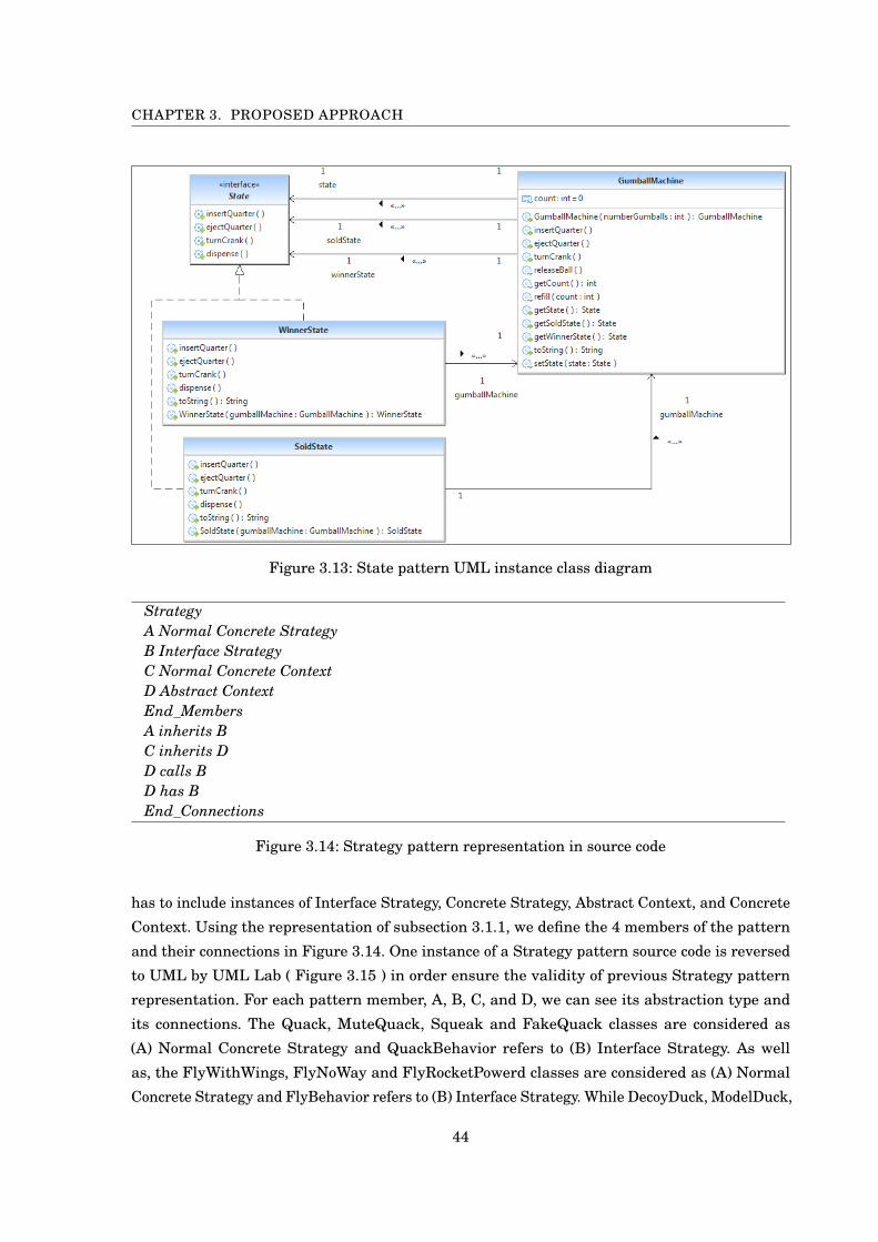
CHAPTER 3. PROPOSED APPROACH
Figure 3.13: State pattern UML instance class diagram
StrategyA Normal Concrete StrategyB Interface StrategyC Normal Concrete ContextD Abstract ContextEnd_MembersA inherits BC inherits DD calls BD has BEnd_Connections
Figure 3.14: Strategy pattern representation in source code
has to include instances of Interface Strategy, Concrete Strategy, Abstract Context, and Concrete
Context. Using the representation of subsection 3.1.1, we define the 4 members of the pattern
and their connections in Figure 3.14. One instance of a Strategy pattern source code is reversed
to UML by UML Lab ( Figure 3.15 ) in order ensure the validity of previous Strategy pattern
representation. For each pattern member, A, B, C, and D, we can see its abstraction type and
its connections. The Quack, MuteQuack, Squeak and FakeQuack classes are considered as
(A) Normal Concrete Strategy and QuackBehavior refers to (B) Interface Strategy. As well
as, the FlyWithWings, FlyNoWay and FlyRocketPowerd classes are considered as (A) Normal
Concrete Strategy and FlyBehavior refers to (B) Interface Strategy. While DecoyDuck, ModelDuck,
44

3.1. DESIGN PATTERNS DETECTION
Figure 3.15: Strategy pattern UML instance class diagram
RubberDuck, RedHeadDuck and MallardDuck classes represent (C) Normal Concrete Context
member, and Duck class represents (D) Abstract Context member.
3.1.3 DP-CoRe Design Pattern Detection Algorithm
3.1.3.1 Parsing Source Code to extract the Abstract Syntax Tree (AST)
We used the proposed design pattern detection algorithm by Diamantopoulos et al. [24] that is
based on extraction of the Abstract Syntax Tree (AST) for each Java file in the project under
study, using the Java Compiler Tree API that extracts Java classes and relationships between
them.
The Java Compiler Tree API provides programmatic access to the Java compiler itself and
allows developers to compile Java classes from source files on the fly from application code. It
provides access to Java syntax parser functionality. By using this API, Java developers have
the ability to directly plug into syntax parsing phase and post-analyze Java source code being
compiled. It is a very powerful API which is heavily utilized by many static code analysis tools
and extract the Abstract Syntax Tree (AST) which can be used for deeper analysis of the source
elements.
When Java Compiler Tree API is working, each time Java class file is scanned, corre-
sponding Class Object is created, filled and saved into the Classes Hashmap. This API, is able to
get the abstraction type of each class (e.g. Normal, Abstract, Interface, etc.) and the connection
with other classes (e.g. inherits, calls, creates, has, uses and references) based on two types of
45

CHAPTER 3. PROPOSED APPROACH
structural representations for source code and design patterns (Table 3.1, 3.2). An example is
shown in Figure 3.16.
Figure 3.16: Example of Extracting Connections for a Car Class
Figure 3.16 describes an example of extracting the connections of a Car class which
interacts with three classes. It inherits the Vehicle class and has two objects of type Model and
Fuel. Additionally, Car references the Model in its constructor, where the Fuel object is also
created. Finally, the getter function of Car also implies that it uses the Model class, while Car
also calls a method of Fuel to add fuel to its tank. Hence, we can define 7 connections among the
classes in this example, which are shown in the annotations on the right of Figure 3.16.
In addition, for every new variable, method or relation encountered, a corresponding object
is created and saved to its corresponding Class Object. An example is shown in Figure 3.17. The
final output of parsing AST is a HashMap containing all Class Objects.
Figure 3.17 describes an example of the corresponding Class Object that is created to
represent Java class file in the proposed approach. Class Object contains abstraction type which
can be any of the following: Abstract Interface Abstracted Normal Any, and list of class names
that is being implemented by this Class Object. As well as, Methods, variables and access
modifiers is saved inside the Class Object. Finally, the Class Object contains a list of connections
between objects and the relations starting from this Class Object.
46

3.1. DESIGN PATTERNS DETECTION
Figure 3.17: Example of Class Object
3.1.3.2 Detection of Design Pattern Candidates
Upon having extracted Java classes as objects and relationships of the examined software project,
design pattern candidates are then detected using the DP-CoRe detection algorithm, as described
in [24] and it is shown in Figure 3.18. It receives as input the list of the examined software
Algorithm 1 Design Pattern Detection AlgorithmInputs: Pro jectClassesAsListOb jects , DesignPatternMembersResult: DesignPatternAsListCandidatesd ← 0Detect( Objects, Members, Candidate, d ) :if d < Members.length() then
Member ← Members[d]while Object in Objects do
if abstraction (Object, Member) AND connections (Object, Member) thenNextClassObjects.Remove( Object )Candidate.Add( Object )Detect( NextClassObjects, NextMembers, Candidate, d+1)
endend
endAdd Candidate to DesignPatternCandidates
Figure 3.18: Design Pattern Detection Algorithm
project classes as objects which is extracted in the previous step in the formats of Class Object
(Figure 3.17). As well as the design pattern to be detected in the format defined in the previous
subsections 3.1.2, where for each pattern member (A, B, C, .etc members) is converted to an object
in the formats of Class Object (Figure 3.17) then it is added to pattern members list.
If the algorithm iterates over all possible permutations of class, it would be computationally
47

CHAPTER 3. PROPOSED APPROACH
inefficient. For Instance, if the project under study contains 20 classes and a pattern with 4
members, this method would check more than one hundred thousand of permutations. That’s
why the designed algorithm works recursively to finds pattern candidates.
The algorithm initialized with depth equal to 0, then get the pattern member in index 0
and iterating over the first class object to check whether its abstraction and its connections are
the same with pattern member in index 0. If the matching is done, the detecting function is called
recursively on the remaining classes except the already matched class, updated Candidate and
the depth is also incremented to get pattern member in the next index, else the recursive function
stops. When all pattern members are matched successfully, then the Candidate is added to the
detected pattern Candidates. An output example of [24] pattern detection approach is shown in
Figure 3.19.
Candidate of Pattern Strategy:A (Concrete Strategy): FlyRocketPoweredB (Strategy): FlyBehaviorC (Concrete Context): DecoyDuckD (Context): Duck
Figure 3.19: Output example of detection phase
Nevertheless, we observed that the detection approach by Diamantopoulos et al. [24]
could miss the detection of some pattern candidates, if the examined project has some classes
with the same name. Therefore, we applied refactoring method on the repeated classes, then
run the detection algorithm which receives as input the examined repository projects files and
the pattern detection rules to be detected. Upon having extracted pattern candidates for each
examined project in open-source repository, the next step is to calculate the conformance scores for
each pattern candidate by comparing the candidate implementations versus predefined pattern
characteristics in order to identify pattern violations. This will be discussed in detail in next
subsection 3.2.
3.2 Design Pattern Violation Identification
As the focus of this thesis lies on enhancing design of extensibility using design pattern, the
design violations should be detected in early stages of evolution and based on their severity and
overall pattern performance decide to keep, refactor or discard them. That is why the thesis is
centered on the identification of violations against design pattern definitions at first. Secondly
focuses on measurement of their impact on source code.
Upon having the list of detected design pattern candidates as output of previous section 3.1,
the second phase of the proposed automated tool (DPVIA) is starting to evaluate the conformance
48

3.2. DESIGN PATTERN VIOLATION IDENTIFICATION
of pattern candidate implementations compared to pattern definitions based on a predefined set
of characteristics, in order to understand the violations that can occur when a design pattern is
applied.
Subsequently, the presence or absence of the abstraction of pattern candidate members
and the connections among pattern members, if they are different from the predefined pattern
characteristics, it is considered as a violation, as discussed in previous chapter of subsection
Software Design Decay 2.1.3.
3.2.1 Specify Design Pattern Predefined Characteristics
For each design pattern definition which was mentioned in the previous chapter of subsection
2.1.2, a set of predefined characteristics is created to address pattern specifications. In addition,
we arrange them with consideration of programming language specifications, which shaped the
concrete implementation. For purpose of obtaining characteristics comparable with patterns in
real projects, which are implemented in one particular language have to be considered as well.
We have decided to use the Java object oriented language because there is fairly large amount of
pattern definitions available and easily accessible in open source projects.
In combination of design pattern definitions and Java language specific requirements,
predefined characteristics of the selected design patterns of subsection 3.1.2 are created as
following examples based on the representation of objects and relationships methodology defined
in [24] ( Table 3.1 and 3.2 ) to specify design pattern characteristics.
For instance, according to GoF [7] pattern definitions, Simple Factory, Factory Method,
Adapter, Decorator, Observer, State, and Strategy predefined characteristics are described in
Tables 3.3 , 3.4 , 3.5 , 3.6 , 3.7 , 3.8 , 3.9 respectively to show how characteristics tables were
derived from definitions.
All predefined characteristics have the same scoring weight, all differences are treated
equally. But we acknowledge that the scoring weights should be different from one characteristic
to another and are determined by experts. For example the conforming of Strategy pattern
predefined characteristics are:
• Strategy (Required abstraction conforming)
– declares an interface common to all supported strategies.
– Context uses this interface to call the strategy defined by a ConcreteStrategy (Required
relationship).
• ConcreteStrategy (Required abstraction conforming)
49

CHAPTER 3. PROPOSED APPROACH
Table 3.3: SimpleFactory Design Pattern Predefined Characteristics
Abstraction Predefined CharacteristicsPatternName
Pattern Members (classes) Abstraction Type Conforming
SimpleFactoryPattern
ConcreteProduct Abstraction.Normal requiredProduct Abstraction.Abstract requiredConcreteCreator Abstraction.Normal requiredCreator Abstraction.Normal required
Relationship Predefined CharacteristicsRelation Relation From Relation To Connection Type ConformingInheritance ConcreteProduct Product Connection.inherits requiredDependency ConcreteCreator Product Connection.uses optionalComposition ConcreteCreator ConcreteProduct Connection.creates requiredAggregation Creator ConcreteCreator Connection.has requiredAssociation Creator ConcreteCreator Connection.references optionalDependency Creator ConcreteCreator Connection.calls optionalDependency Creator Product Connection.uses requiredDependency Creator Productr Connection.calls optional
Table 3.4: Factory Method Design Pattern Predefined Characteristics
Abstraction Predefined CharacteristicsPatternName
Pattern Members (classes) Abstraction Type Conforming
FactoryMethodPattern
ConcreteProduct Abstraction.Normal requiredProduct Abstraction.Abstract requiredConcreteCreator Abstraction.Normal requiredCreator Abstraction.Abstract required
Relationship Predefined CharacteristicsRelation Relation From Relation To Connection Type ConformingInheritance ConcreteProduct Product Connection.inherits requiredInheritance ConcreteCreator Creator Connection.inherits requiredDependency ConcreteCreator Product Connection.uses optionalComposition ConcreteCreator ConcreteProduct Connection.creates requiredDependency Creator Product Connection.uses requiredDependency Creator Product Connection.calls optional
– implements a concrete strategy using the Strategy interface (Required relationship).
• Context (Required abstraction conforming)
– is configured with a ConcreteStrategy object (Required relationship).
50

3.2. DESIGN PATTERN VIOLATION IDENTIFICATION
Table 3.5: Adapter Design Pattern Predefined Characteristics
Abstraction Predefined CharacteristicsPatternName
Pattern Members (classes) Abstraction Type Conforming
AdapterPattern
ConcreteAdaptee Abstraction.Normal requiredAdaptee Abstraction.Interface requiredAdapter Abstraction.Normal requiredTarget Abstraction.Interface requiredClient Abstraction.Normal optional
Relationship Predefined CharacteristicsRelation Relation From Relation To Connection Type ConformingRealization ConcreteAdaptee Adaptee Connection.inherits requiredRealization Adapter Target Connection.inherits requiredAggregation Adapter Adaptee Connection.has requiredAssociation Adapter Adaptee Connection.references requiredDependency Adapter Adaptee Connection.calls requiredComposition Client Adapter Connection.creates optionalComposition Client ConcreteAdaptee Connection.creates optionalAggregation Client Target Connection.has optional
Table 3.6: Decorator Design Pattern Predefined Characteristics
Abstraction Predefined CharacteristicsPatternName
Pattern Members (classes) Abstraction Type Conforming
DecoratorPattern
ConcreteComponent Abstraction.Normal requiredComponent Abstraction.Abstracted requiredConcreteDecorator Abstraction.Normal requiredDecorator Abstraction.Abstracted required
Relationship Predefined CharacteristicsRelation Relation From Relation To Connection Type ConformingInheritance ConcreteComponent Component Connection.inherits requiredInheritance Decorator Component Connection.inherits requiredInheritance ConcreteDecorator Decorator Connection.inherits requiredAggregation ConcreteDecorator Component Connection.has requiredAssociation ConcreteDecorator Component Connection.references optionalDependency ConcreteDecorator Component Connection.calls optional
– maintains a reference to a Strategy object (Required relationship).
– may define an interface that lets Strategy access its data (Optional relationship).
51

CHAPTER 3. PROPOSED APPROACH
Table 3.7: Observer Design Pattern Predefined Characteristics
Abstraction Predefined CharacteristicsPatternName
Pattern Members (classes) Abstraction Type Conforming
ObserverPattern
ConcreteObserver Abstraction.Normal requiredObserver Abstraction.Interface requiredConcreteSubject Abstraction.Normal requiredSubject Abstraction.Abstracted required
Relationship Predefined CharacteristicsRelation Relation From Relation To Connection Type ConformingRealization ConcreteObserver Observer Connection.inherits requiredAggregation ConcreteObserver Subject Connection.has optionalAssociation ConcreteObserver Subject Connection.references optionalDependency ConcreteObserver Subject Connection.calls optionalRealization ConcreteSubject Subject Connection.inherits requiredAssociation ConcreteSubject Observer Connection.references optionalDependency ConcreteSubject Observer Connection.calls requiredAssociation Subject Observer Connection.references required
Table 3.8: State Design Pattern Predefined Characteristics
Abstraction Predefined CharacteristicsPatternName
Pattern Members (classes) Abstraction Type Conforming
StatePattern
ConcreteState Abstraction.Normal requiredState Abstraction.Interface requiredStateContext Abstraction.Normal required
Relationship Predefined CharacteristicsRelation Relation From Relation To Connection Type ConformingRealization ConcreteState State Connection.inherits requiredAggregation ConcreteState StateContext Connection.has requiredAssociation ConcreteState StateContext Connection.references optionalAggregation StateContext State Connection.has requiredComposition StateContext ConcreteState Connection.creates required
• ConcreteContext (Optional abstraction conforming).
– usually inherits the context and creates ConcreteStrategy object (Required relation-
ships if Strategy pattern contains ConcreteContext as one of it’s members).
Absence of required characteristic is considered a clear violation, while absence of optional
52
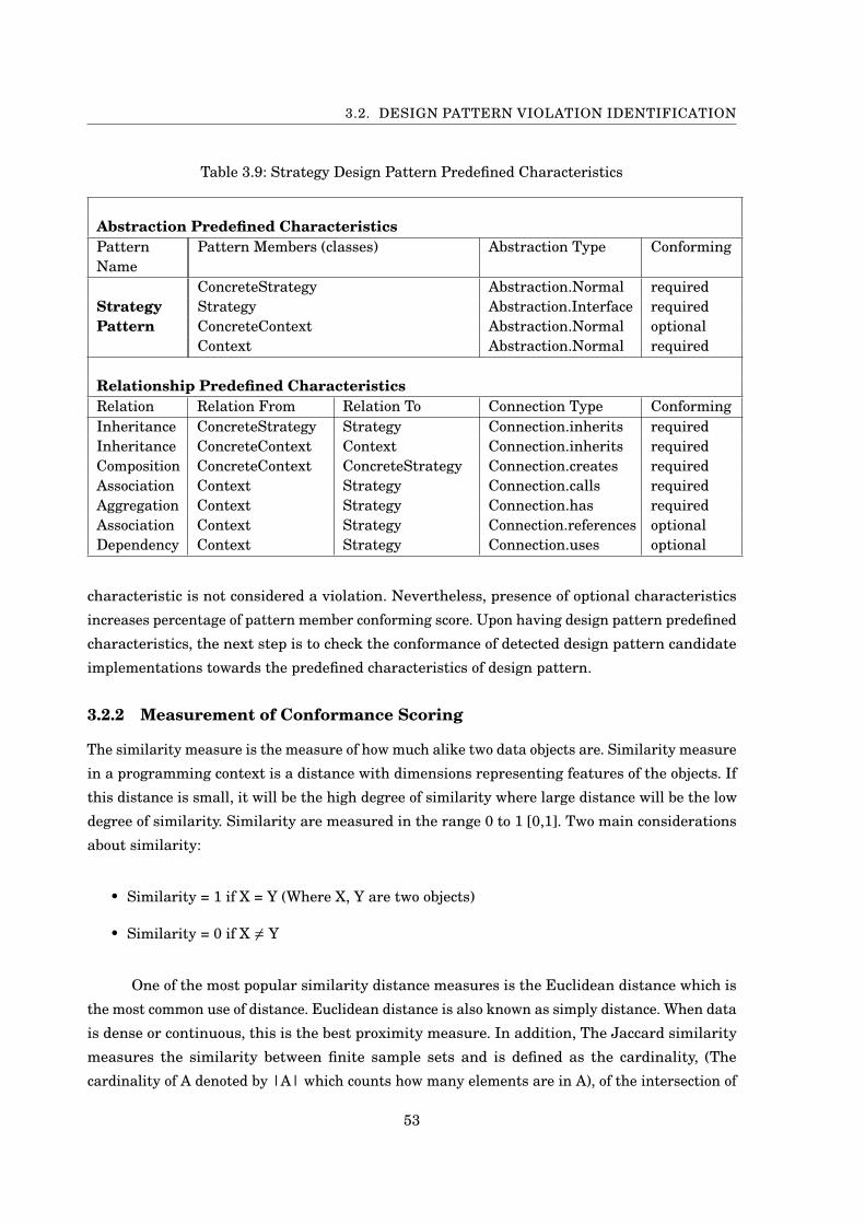
3.2. DESIGN PATTERN VIOLATION IDENTIFICATION
Table 3.9: Strategy Design Pattern Predefined Characteristics
Abstraction Predefined CharacteristicsPatternName
Pattern Members (classes) Abstraction Type Conforming
StrategyPattern
ConcreteStrategy Abstraction.Normal requiredStrategy Abstraction.Interface requiredConcreteContext Abstraction.Normal optionalContext Abstraction.Normal required
Relationship Predefined CharacteristicsRelation Relation From Relation To Connection Type ConformingInheritance ConcreteStrategy Strategy Connection.inherits requiredInheritance ConcreteContext Context Connection.inherits requiredComposition ConcreteContext ConcreteStrategy Connection.creates requiredAssociation Context Strategy Connection.calls requiredAggregation Context Strategy Connection.has requiredAssociation Context Strategy Connection.references optionalDependency Context Strategy Connection.uses optional
characteristic is not considered a violation. Nevertheless, presence of optional characteristics
increases percentage of pattern member conforming score. Upon having design pattern predefined
characteristics, the next step is to check the conformance of detected design pattern candidate
implementations towards the predefined characteristics of design pattern.
3.2.2 Measurement of Conformance Scoring
The similarity measure is the measure of how much alike two data objects are. Similarity measure
in a programming context is a distance with dimensions representing features of the objects. If
this distance is small, it will be the high degree of similarity where large distance will be the low
degree of similarity. Similarity are measured in the range 0 to 1 [0,1]. Two main considerations
about similarity:
• Similarity = 1 if X = Y (Where X, Y are two objects)
• Similarity = 0 if X 6= Y
One of the most popular similarity distance measures is the Euclidean distance which is
the most common use of distance. Euclidean distance is also known as simply distance. When data
is dense or continuous, this is the best proximity measure. In addition, The Jaccard similarity
measures the similarity between finite sample sets and is defined as the cardinality, (The
cardinality of A denoted by |A| which counts how many elements are in A), of the intersection of
53

CHAPTER 3. PROPOSED APPROACH
sets divided by the cardinality of the union of the sample sets. Suppose the developer wants to
find Jaccard similarity between two sets A and B it is the ratio of cardinality of A ∩ B and A ∪ B.
In this work, we used Hamming Distance algorithm to denote the difference between
two binary vectors of equal length. It is the number of positions at which the corresponding
symbols are different. The Hamming Code earned Richard Hamming the Eduard Rheim Award
of Achievement in Technology in 1996, two years before his death. Hamming’s additions to
information technology have been used in such innovations as modems and compact discs [71].
For instance, the Hamming Distance of two binary vectors whereas vector 1: [1, 0, 0, 1, 0,
0, 1, 0, 1, 1, 0, 1] vector 2: [1, 0, 1, 0, 0, 0, 1, 0, 0, 0, 1, 0] is calculated as in the following steps:
• Step 1 Ensure the two vectors are of equal length. The Hamming distance can only be
calculated between two vectors of equal length.
• Step 2 Compare the first two bits in each vector. If they are the same, record a "0" for that
bit. If they are different, record a "1" for that bit. In this case, the first bit of both vectors is
"1," so record a "0" for the first bit.
• Step 3 Compare each bit in succession and record either "1" or "0" as appropriate. vector 1:
[1, 0, 0, 1, 0, 0, 1, 0, 1, 1, 0, 1] vector 2: [1, 0, 1, 0, 0, 0, 1, 0, 0, 0, 1, 0] Record: [0, 0, 1, 1, 0, 0,
0, 0, 1, 1, 1, 1]
• Step 4 Add all the ones and zeros in the record together to obtain the Hamming distance.
Hamming distance = 0 + 0 + 1 + 1 + 0 + 0 + 0 + 0 + 1 + 1 + 1 + 1 = 6
The two binary vectors have 6 different bits, subsequently the similarity 1 - ( 6 / 12) = 0.5, this is
what constitutes the cornerstone of formula (3.1).
The purpose of measurement is obtaining a conformance scores for pattern definitions
predefined characteristics and their implementations in source code. For all detected pattern
candidate members, our proposed conformance algorithm, is shown in Fig. 3.20, receives two
inputs the pattern candidate member object as well as the corresponding pattern characteristics
object as parameters for CheckConformance function. At first, the algorithm is initialized with
empty scores matrix then iterating over all possible characteristics, check characteristic type (e.g.
abstraction or connection) then compare it with the corresponding pattern candidate member and
add value to similarity scores matrix according to fulfilled condition. While doing so, we noticed
that only the limited scenarios depicted in Table 3.10 would apply.
Similarity scoring is represented by a matrix of two vectors, where the first vector refers
to absence or presence (0 or 1) of a characteristic in the pattern definition characteristics while
54
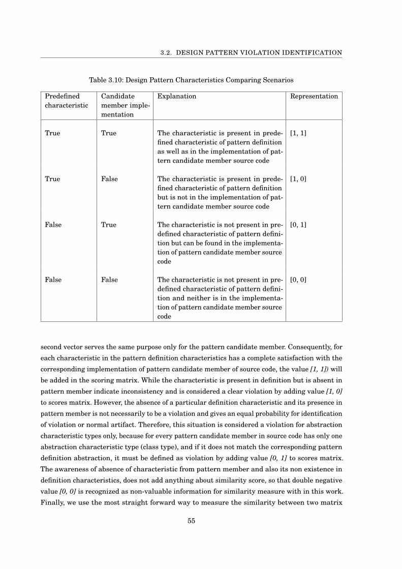
3.2. DESIGN PATTERN VIOLATION IDENTIFICATION
Table 3.10: Design Pattern Characteristics Comparing Scenarios
Predefinedcharacteristic
Candidatemember imple-mentation
Explanation Representation
True True The characteristic is present in prede-fined characteristic of pattern definitionas well as in the implementation of pat-tern candidate member source code
[1, 1]
True False The characteristic is present in prede-fined characteristic of pattern definitionbut is not in the implementation of pat-tern candidate member source code
[1, 0]
False True The characteristic is not present in pre-defined characteristic of pattern defini-tion but can be found in the implementa-tion of pattern candidate member sourcecode
[0, 1]
False False The characteristic is not present in pre-defined characteristic of pattern defini-tion and neither is in the implementa-tion of pattern candidate member sourcecode
[0, 0]
second vector serves the same purpose only for the pattern candidate member. Consequently, for
each characteristic in the pattern definition characteristics has a complete satisfaction with the
corresponding implementation of pattern candidate member of source code, the value [1, 1]) will
be added in the scoring matrix. While the characteristic is present in definition but is absent in
pattern member indicate inconsistency and is considered a clear violation by adding value [1, 0]
to scores matrix. However, the absence of a particular definition characteristic and its presence in
pattern member is not necessarily to be a violation and gives an equal probability for identification
of violation or normal artifact. Therefore, this situation is considered a violation for abstraction
characteristic types only, because for every pattern candidate member in source code has only one
abstraction characteristic type (class type), and if it does not match the corresponding pattern
definition abstraction, it must be defined as violation by adding value [0, 1] to scores matrix.
The awareness of absence of characteristic from pattern member and also its non existence in
definition characteristics, does not add anything about similarity score, so that double negative
value [0, 0] is recognized as non-valuable information for similarity measure with in this work.
Finally, we use the most straight forward way to measure the similarity between two matrix
55

CHAPTER 3. PROPOSED APPROACH
Algorithm 2 The proposed conformance algorithmResult: PercentageO f PatternMemberScoreCheckConformance( PatternCharacteristics C, PatternCandidateMember M)
ScoresMatrix ← null, i ← 0while characteristic in C do
if C.characteristic is AbstractionType thenif C.getAbstraction() and M.getAbstraction() then
Scores[i]← [1,1]else if C.getAbstraction() and ! M.getAbstraction() then
Scores[i]← [1,0]else if ! C.getAbstraction() and M.getAbstraction() then
Scores[i]← [0,1]endif C.characteristic is ConnectionType then
if C.getConnection() and M.getConnection() thenScores[i]← [1,1]
else if C.getConnection() and ! M.getConnection() thenScores[i]← [1,0]
endprint violation details and suggested solution
i ← i+1endreturnPercentageO f PatternMemberScore ← (1 − 1
ScoresSize∑ScoresSize
k=1 Scores1stvector[k] ⊗Scores2ndvector[k])∗100
Figure 3.20: The proposed conformance algorithm
vectors and return the conformance score by formula (3.1):
PercentageO f PatternMemberScore = (1− 1N
N∑i=1
Ci ⊗Mi)∗100 (3.1)
Where:
PercentageOfPatternMemberScore is the conformance score percentage, N is the similarity matrix
rows (size of characteristics), Ci is the pattern definition characteristic binary value representing
by the 1st vector of similarity score matrix, and Mi is the pattern candidate member binary value
representing by the 2nd vector of similarity score matrix.
An illustration of design pattern violation identification: For example, in Strategy
design pattern, consider the following 3 Strategy candidate instances, shown in Table 3.11 and
visualized in Figure 3.21, are detected by approach by Diamantopoulos et al. [24] in the first
phase of DPVIA tool. Strategy pattern, in this example, represents a family of Quack Behaviour
strategies , encapsulate each one, and make them interchangeable. Strategy lets the algorithm
vary independently from clients that use it. Each candidate has 4 members:
56

3.2. DESIGN PATTERN VIOLATION IDENTIFICATION
Table 3.11: Strategy Candidate Instances
Pattern Members Candidate #1 Candidate #2 Candidate #3ConcreteStrategy Quack Squeak MuteQuackStrategy QuackBehavior QuackBehavior QuackBehaviorConcreteContext MallardDuck RubberDuck DecoyDuckContext Duck Duck Duck
Figure 3.21: Strategy candidate instances UML class diagram
• ConcreteStrategy
• Strategy
• ConcreteContext
• Context
As shown in Table 3.11, class Duck represents Context member of the three Strategy candidates.
In this example, we show how our proposed approach measures the conformance of Duck class
towards Context member of Strategy predefined characteristics described in Table 3.9, using the
proposed conformance algorithm showed in Figure 3.20, as following in Table 3.12. Using formula
(3.1), percentage of pattern member conformance score (class Duck) = (1 - 1/5) * 100 = 80 %.
Because of class Duck implementation missed calling quackBehavior.quack(); to perform quack
behavior, it is considered a clear violation. Assume that class Duck does not define an interface
that lets Strategy access its data (Optional relationships), this absence of optional connections is
not considered a violation but the conformance score will be (1 - 1/3) * 100 = 66.66 %.
After measuring the conformance scores for all pattern candidate members, the average
is calculated for the pattern candidate as a whole and the score is reported to the developer in
57

CHAPTER 3. PROPOSED APPROACH
Table 3.12: Measurement of Conformance Scoring Example
Predefined Characteristic Patternmember(Context)
Candidatemember(Duck)
Scores Matrix
Abstraction.Normal (required) True True [1, 1]
Connection.calls (required) to Strategy True False [1, 0]
Connection.has (required) to Strategy True True [1, 1]
Connection.references (optional) to Strategy True True [1, 1]
Connection.uses (optional) to Strategy True True [1, 1]
addition to in order to produce a preliminary identification of violation details, and suggested
solutions based on previously defined characteristics. The proposed approach suggests refactoring
for all violations. For instance, the missing of call connection in class Duck to perform quack
behavior that detected as violation could be solved as following:
Recommendation - Class( Duck ) should call (invoke function quack) of class QuackBehavior.
Such suggestions help developers to resolve violations and providing a valuable insight on
"health" of system under study and possible existence of violations within its source code. In
order to distinguish between code related to design pattern realization and code that is harmful
causes a decay of system design.
3.3 Verification of the Initial Detected Violations
Finally, the last phase verifies the detected violations by examining relationships between entities
participated in those violations based on the presence / absence of relationship scenarios between
those entities, in system requirement specifications (SRS) document. In order to take business
logic constrains into considerations before accounting those detected violations in the conformance
score.
In our proposed approach, the Natural Language Processing Toolkit is required to extract
the entities relationship scenarios of the project under study. We used Stanford CoreNLP Natural
Language Processing Toolkit [70] and integrate the proposed tool DPVIA with a Java implemen-
tation of Stanford Open Information Extraction (open IE) as described in the paper of Gabor
Angeli et al. [72]. Open IE refers to the extraction of relation tuples, typically binary relations,
from plain text. The central difference is that the schema for these relations does not need to
58

3.3. VERIFICATION OF THE INITIAL DETECTED VIOLATIONS
be specified in advance; typically the relation name is just the text linking two arguments. The
OpenIE system can be run both through the command line, and through the CoreNLP API.
The open IE first splits each sentence into a set of entailed clauses. Each clause is then
maximally shortened, producing a set of entailed shorter sentence fragments. These fragments
are then segmented into OpenIE triples, and output by the system. An illustration of the process
is given for an example sentence below in Figure 3.22:
"Each employee opens the control panel, view all complaints and solve client problems"
Figure 3.22: Stanford OpenIE example
Using the Stanford CoreNLP Natural Language Processing Toolkit [70] and openIE [72] to
extract entities relationships in order to confirm the detected violation, if there are relationships
in business logic between violation entities, or discard the detected violation, if there is no
relationship in business logic between violation entities.
Finally, the proposed approach reports the pattern instance scoring with refactoring
suggestion to modify Java application with minimum impact. In order to guide the developer to
enhance and extend software applications by supporting an assessment score of current source
code implementations and recommendation to solve the design violations.
59

CH
AP
TE
R
4IMPLEMENTATION, PRACTICAL EXPERIMENTS AND RESULTS
P ractical experiments are done to study, using the proposed approach, how would designpatterns be applied in real environment of open source projects in order toassess the implementations of software design patterns, detect design pattern
violations, and offer recommendations for extending the design or maintaining thecurrent version of software application.
4.1 Implementation of the Proposed Approach
Our implementation of the proposed approach1 is implemented in Java programming language.
We have decided to use the Java object oriented language. It is one of mainstream program-
ming languages nowadays, thus there is fairly large amount of pattern definitions available.
Consequently, finding open source projects with easily accessible source codes is not an issue.
As mentioned earlier in the previous chapter, the details of DPVIA: Design Pattern Viola-
tions Identification and Assessment approach, DPVIA Tool offering a Command Line Interface
(CLI) to obtain the design violations identification of all repository projects and report the confor-
mance scores for the pattern candidates as well as violations details in the form of a document
has the name of the examined project. In addition, it produces graphs indicating the percentage
of violation that has been committed.
The automated tool is free and available to download from Git or checkout with SVN us-
ing the web URL: https: // github. com/ TamerAbdElaziz/ DPVIA. git , then unzip the down-
1The automated tool is free and is available to download at https://github.com/TamerAbdElaziz/DPVIA
61

CHAPTER 4. IMPLEMENTATION, PRACTICAL EXPERIMENTS AND RESULTS
loaded file. There will be two folders named "pattern" and "Repository", as well executable Jar
file named "dpvia", then follow the following instructions:
• The DPVIA is able to detect successfully 7 design patterns as they are represented in
previous chapter of subsection 3.1.2. It offers the ability to define custom patterns by the
developer. Any design pattern characteristics could be defined and added to folder that
named "pattern". DPVIA is quite flexible and could be extended the detection of any design
pattern.
• The developer is able to set the examined Java project source code files on the folder called
"Repository". As well, many projects can be examined at one time.
• Run in batch (command line) mode of Jar file which called dpvia, and execute using
command: java -jar dpvia.jar
The inputs to DPVIA tool is any set of Java projects source code that need to be maintained or
extended. On the other hand, the final output is formatted as comma-separated values (CSV) file
stores tabular data (numbers and text) in plain text about each design pattern member assess-
ment and recommendation of solution if there is violations. In addition to CSV file, the assessment
is visualized using Bar Chart and the recommendations is written in a word document.
4.2 Practical Experiments
DPVIA is evaluated in Java project of Head First Design Patterns Book code 2 which provides
an interesting example project that has a proper implementations of well-known design pattern
patterns (e.g. Simple Factory, Factory Method, Adapter, Decorator, Observer, State and Strategy).
Note, we have modified some instances of this project to make them contain violations. The
validation of the proposed tool (DPVIA) is reformed using two evaluation experiments 4.2.1 and
4.2.2.
In order to measure the accuracy of DPVIA tool, precision and recall are calculated.
Precision (also called positive predictive value) is the fraction of relevant instances among the
retrieved instances, while recall (also known as sensitivity) is the fraction of relevant instances
that have been retrieved over the total amount of relevant instances. Both precision and recall
are therefore based on an understanding and measure of relevance.
• A number of candidates was correctly detected = True positive (candidates are a correct
pattern and they are detected).2Head First Design Patterns Book code is free and available to download it from Headfirstlabs website using the
web URL: http: // www. headfirstlabs. com/ books/ hfdp/ HeadFirstDesignPatterns_ code102507. zip .
62

4.2. PRACTICAL EXPERIMENTS
• A number of all correct candidates = True positive (candidates are a correct pattern and
they are detected) + False negative (candidates are a correct pattern and they are not
detected).
• A number of all detected candidates = True positive (candidates are a correct pattern
and they are detected) + False positive (candidates are not correct pattern and they are
detected).
Recall = A number of candidates was correctly detected / A number of all correct candidates
e.g. recall = True positive / (True positive + False negative).
Precision = A number of candidates was correctly detected / A number of all detected
candidates e.g. precision = True positive / (True positive + False positive).
Accuracy = (True positive + True negative) / all number of possible candidates e.g. Accuracy
= (True positive + True negative)/ (True positive+ False positive + True negative + False negative).
4.2.1 The First Practical Experiment
Integration of our approach with DP-CoRe tool (in DPVIA first phase) has succeeded in deter-
mining all design pattern candidates with accuracy 70.73% of the detection algorithm where
24 of pattern candidates were detected incorrectly (false positive 29.26%) while 58 of pattern
candidates were detected correctly. Moreover, by reviewing the source code manually, we found the
total number of the correct pattern candidates in source code is 58 candidates, so no candidates
were missed without detection, but some of the detected instances are not fully representative of
design patterns. Pattern detection algorithm by DP-CoRe achieved 70.73% precision and 100%
recall.
Then, DPVIA (in DPVIA second phase) has measured the conformance score for each
detected pattern candidate in order to identify pattern violations and report the conformance
scores average, satisfied and violated instances of the examined project, the results are shown in
Table 4.1. In the fourth column shows the average of conformance scoring for each pattern in the
range of 92.5% to 100%. The conformance scoring was verified manually by reviewing the source
code of the satisfied and violated instances, we found 24 instances were identified as violated
instances incorrectly (false positive 29.26% of the proposed conformance scoring algorithm). The
proposed conformance algorithm achieved 70.73% precision and 100% recall.
Consequently, the conformance algorithm has false disclosure due to the measurement of
conformance score of some pattern instances were detected in the detection phase incorrectly and
the reliance only on predetermined characteristics of each design pattern while it should not be
considered a violation according to business logic and software requirements. For this reason,
63

CHAPTER 4. IMPLEMENTATION, PRACTICAL EXPERIMENTS AND RESULTS
Table 4.1: Validating The Proposed Approach Over Head First Design Patterns Book Code Project
Design Patterns Detection Design pattern violation identificationPatternname
#Instances #IncorrectInstancesdetection
ConformanceScore %
#SatisfiedInstances
#ViolatedInstances
#IncorrectInstancesScoring
Adapter 2 0 100% 2 0 0Decorator 16 0 96.2% 8 8 0FactoryM 16 0 100% 16 0 0SFactory 4 0 100% 4 0 0Observer 4 0 92.5% 2 2 0State 5 0 96% 3 2 0Strategy 35 24 93.9% 10 25 24Total 82 24 45 37 24% of Total 29.26% 54.87% 45.12% 29.26%
we suggested the verification phase for the detected violations. Verification phase could be done
by software developers but it needs a lot of time and effort. If the relationships between system
entities in the SRS document are presented to the software developer, it will be easy to approve or
discard the violations based on the presence or absence relationships between violation members
or perform the verification phase automatically.
The proposed tool (DPVIA) is integrated with Stanford Open Information Extraction (open
IE) [72] that extracts open-domain relation triples, representing a subject, a relation, and the
object of the relation from plain text. Open IE can be accessed through the Stanford CoreNLP
API3 through the standard annotation pipeline to extract the relations between violation members
from SRS plain text. An illustration of the process is given for an example sentence below which
is written in SRS document and represented in Figure 4.1:
"The DecoyDuck should have a MuteQuack behavior, and fly with FlyRocketPowered"
Figure 4.1: Stanford Open Information Extraction of relations between entities
According to the extraction of relations between entities, the entity DecoyDuck has only
two relations with MuteQuack behavior and FlyRocketPower. However, during pattern detection
and violation identification, DecoyDuck entity participates as member class in 7 detected Strategy
instances where 2 instances conformed the predefined characteristics while other 5 instances
did not. The five violated instances, #4, #9, #14, #24, #29, have a missing connection from
3Stanford CoreNLP https://stanfordnlp.github.io/CoreNLP/
64

4.2. PRACTICAL EXPERIMENTS
class(DecoyDuck) to class (Squeak), class (FakeQuack), class (Quack), class (FlyWithWings) or
class (FlyRocketPowered) respectively. So that, the violations of Strategy instances #4, #9, #14,
#24 were discarded due to the absence of relationships between violation members in the result
of open IE relations extraction. The only instance #29 is considered as violation where DecoyDuck,
in source code, flies with another flying behavior and does not fly with FlyRocketPowered behavior
as required. The result of instance #29, as shown in the Figure 4.2, shows how DPVIA tool is able
to detect design pattern violations and recommend suitable refactoring solutions.
Candidate of Pattern Strategy (29):A(Concrete Strategy): FlyRocketPoweredB(Strategy): FlyBehaviorC(Concrete Context): DecoyDuckD(Context): Duck
Design pattern violation identification:
FlyRocketPowered (Evaluation : 100.0 %)
FlyBehavior (Evaluation : 100.0 % )
DecoyDuck ( Evaluation : 66.0 % )Recommendation: Class( DecoyDuck ) should create new object of class : FlyRocketPoweredApproved: This violation has to be solved according to the relationship between ( decoyduck )and ( flyrocketpowered ) in SRS document.
Duck (Evaluation : 100.0 % )
Total score : 91.5 %
Figure 4.2: Example Output of DPVIA
One of the most important results of the verification phase is the reduction of false positive
instances scoring and is changed to be more accurate for the proposed conformance scoring
algorithm. Currently, the verification phase of pattern violations works successfully only if the
source code classes have the same system entity names in the SRS document. This issue could be
solved by applying more accurate requirements analysis techniques.
4.2.2 The Second Practical Experiment
For the second experiment, we repeated the same previous experiment with different settings of
design pattern detection algorithm. Tsantalis DPD tool2, uses similarity algorithms, is used to
detect design pattern instances instead of Diamantopoulos et al. [24] algorithm used in previous
experiment 4.2.1, then apply the same conformance scoring algorithm and running over the same
65

CHAPTER 4. IMPLEMENTATION, PRACTICAL EXPERIMENTS AND RESULTS
project of Head First Design Patterns Book code.
Tsantalis DPD tool obtain the final set of detected pattern instances in XMI (XML Metadata
Interchange) format. Wherefore, we created XML parser module (as discussed in subsection 2.3.5)
to prepare the detected pattern instances set to be able to integrate them with the proposed tool.
XMI document is parsed with a DOM parser to get back a tree structure that contains all of the
elements of XMI document. The DOM provides a variety of functions that can be used to examine
the contents and structure of the document. The DOM is a common interface for manipulating
document structures. One of its design goals is that Java code written for one DOM-compliant
parser should run on any other DOM-compliant parser without changes.
We got a set of detected pattern instances by Tsantalis DPD tool, and wrote the instances
in a file named "PatternsDetectedByOtherTools.txt" in the main path of DPVIA tool. The pattern
instances are written in the following formats shown in Figure 4.3. In addition, using these
formats allows any developer to detect the pattern classes by other detection approaches to
measure the conformance score easily and detect pattern violations.
Decorator Espresso A Concrete ComponentDecorator Beverage B ComponentDecorator Soy C Concrete DecoratorDecorator CondimentDecorator D DecoratorEndFactoryMethod NYStyleClamPizza A Concrete ProductFactoryMethod Pizza C Adapter B ProductFactoryMethod NYPizzaStore C Concrete CreatorFactoryMethod PizzaStore D CreatorEnd...End
Figure 4.3: Formats of pattern instances detected by any detection tool
As it is obvious in Table 4.2, Tsantalis DPD tool is totally missed detection of Simple Factory
and Strategy pattern candidates and 15 of pattern candidates were detected incorrectly (false
positive 65.21%) while 8 candidates were detected correctly. As noted by the first experience, the
total number of the correct pattern candidates in source code is 58 candidates, so 50 candidates
were missed without detection (false negative 86.20%). Pattern detection algorithm by Tsantalis
DPD achieved 34.78% precision and 13.79% recall.
Then DPVIA (in DPVIA second phase) has measured the conformance score for each
detected pattern candidate. Note that pattern instances that are detected incorrectly by Tsantalis
66

4.3. DISCUSSION AND ANALYSIS OF RESULTS
DPD might mislead the proposed conformance scoring algorithm (Fig. 3.20) to assess of the
violations correctly. In the fourth column in Table 4.2 shows the average of conformance scoring
Table 4.2: Validating The Conformance Algorithm Integrated With Tsantalis DPD Over HeadFirst Design Patterns Book Code Project
Design Patterns Detection Design pattern violation identificationPatternname
#Instances #IncorrectInstancesdetection
ConformanceScore %
#SatisfiedInstances
#ViolatedInstances
#IncorrectInstancesScoring
Adapter 10 8 69% 0 10 2Decorator 2 0 90% 0 2 2FactoryM 3 1 66.7% 2 1 0SFactory - - - - - -Observer 1 0 87.5% 0 1 1State 7 6 83% 0 7 1Strategy - - - - - -Total 23 15 2 21 6% of Total 65.21% 8.69% 91.30% 26.08%
for each pattern. The Simple Factory and Strategy pattern have not had any conformance
scoring because they were not discovered using Tsantalis DPD. Other design patterns are in
rang of conformance scoring between 66.7% to 90% when they are compared to the predefined
characteristics. The conformance scoring was verified manually by reviewing the source code of
the satisfied and violated instances, we found 6 instances were identified as violated instances
incorrectly (false positive 26.08% of the proposed conformance scoring algorithm). The proposed
conformance algorithm achieved 73.91% precision and 100% recall.
4.3 Discussion and Analysis of Results
The results for the two experiments are shown in Figure 4.4, where P1, P2, P3, P4, P5, P6, and
P7 refer to enumerating patterns Adapter, Decorator, Factory Method, Simple Factory, Observer,
State, and Strategy respectively. In Figure 4.4 (a), there are large deviations between the detected
patterns of the two experiments for the same project of Head First Design Patterns Book code.
This large deviations are mostly due to the detection algorithm of each experiment. Whereas, the
detection algorithm by Diamantopoulos et al. [24] used in our proposed tool (DPVIA), in the first
experiment, allowing developers the flexibility to specify a set of rules to detect any pattern. In
contrast to that, the detection algorithm by Tsantalis DPD tool [37], in the second experiment,
uses similarity algorithms to detect patterns as a black box that do not allow the developer any
control over the detected patterns. On other hand, in Figure4.4 (b), illustration of similarity
scoring percentage of the two experiments.
As already noted, the conformance scoring correctness of pattern instances rely on
67

CHAPTER 4. IMPLEMENTATION, PRACTICAL EXPERIMENTS AND RESULTS
P1 P2 P3 P4 P5 P6 P7
0
10
20
30
#D
etec
ted
Inst
ance
s
1st Exp. 2nd Exp. (a)
P1 P2 P3 P4 P5 P6 P7
0
20
40
60
80
100
Sim
ilari
tySc
orin
g%
1st Exp. 2nd Exp. (b)
Figure 4.4: Comparison between the two evaluation experiments (P1, P2, P3, P4, P5, P6, andP7 refer to enumerating patterns Adapter, Decorator, Factory Method, Simple Factory, Observer,State, and Strategy respectively) (a) number of detected instances (b) Similarity scoring percent-age.
68

4.3. DISCUSSION AND ANALYSIS OF RESULTS
the correct detection of those pattern instances, the interesting aspect of this finding is
showing the importance of pattern detection algorithm in evaluation of design pattern violations.
Also, we observed, DPVIA tool is effective for identifying design pattern violations, due
to the flexibility to use any pattern detection rules as well as determine a set of characteristics
that is used in measurement of conformance scores. Furthermore, concerning execution time,our proposed tool is efficient whereas the identification and assessment of 58 design pattern
instances in Head First Design Patterns Book code project that contains 2,063 Lines of Code
(LoC), required almost 2.5 seconds.
In order to assess the functionality of the tool on any open source project, DPVIA is eval-uated with a dataset containing 5,679,964 (LoC) Lines of Code among 28,669 Java filesin 15 open-source projects, is shown in Table 4.3, (e.g. apachehadoop4, apachehive5, apachephoenix6,
apachepig7, apachetomcat8, apachenutch9, apacheant core10, aspectJAspect Oriented Frameworks11, jEditProgrammers
Text Editor12, JFreeChart13, JHotDraw14, JUnit415, libgdxJava game development framework16, openjmsJava Mes-
sage Service17, and scarabIssue Tracking18 ).
The DPVIA, as its result is shown in Table 4.4, identified the similarity scores for 9,238
pattern instances of seven different GoF patterns: Simple Factory, Adapter, Decorator, Factory
Method, Observer, State and Strategy.The similarity scores indicates the conformance for pat-
tern candidates with pattern definitions characteristics for each project in the repository. We
observed that open source projects have some instances of design patterns do not havea conformance between pattern implementations and their predefined characteristics,and this may cause a lack of maintainability.
In addition, we observed that the proposed approach is able to assess, validate vi-olations, and recommend a suitable solutions for all small and large scale project ofJava applications, as shown in Table 4.3, the DPVIA tool receives as one input 15 open source
Java project with different size. For each project, pattern candidates are detected and measure
the conformance score for all candidate members versus the predefined characteristics of GoF
4Apache hadoop http://hadoop.apache.org/5Apache hive https://hive.apache.org/6Apache phoenix https://phoenix.apache.org/7Apache pig https://pig.apache.org/8Apache tomcat http://tomcat.apache.org/9Apache nutch http://nutch.apache.org/
10Apache ant core http://ant.apache.org/11aspectJ Aspect Oriented Frameworks https://www.eclipse.org/aspectj/12jEdit Programmers Text Editor http://www.jedit.org/13JFreeChart http://www.jfree.org/jfreechart/14JHotDraw http://www.jhotdraw.org/15JUnit4 http://junit.org/junit4/16libgdx Java game development framework https://libgdx.badlogicgames.com/17openjms Java Message Service http://openjms.sourceforge.net/18scarab Issue Tracking https://java-source.net/open-source/issue-trackers/scarab
69

CHAPTER 4. IMPLEMENTATION, PRACTICAL EXPERIMENTS AND RESULTS
Table 4.3: Data Set Of 15 Open Source Projects as input to DPVIA Tool
Project name Lines of Code Source Files Total Detected patternsapache hadoop 1214896 5519 1093apache hive 1034094 3766 838apache phoenix 222353 850 590apache pig 398403 1765 831apache tomcat 537724 2240 64apache nutch 81543 536 50apache ant core 267028 1233 481aspectJ Aspect Oriented Frameworks 710700 7048 522jEditProgrammers Text Editor 195952 598 41JFreeChart 297386 993 4045JHotDraw 6 73421 491 155JUnit4 43073 443 26libgdx Java game development framework 384745 2163 175openjms Java Message Service 112410 576 297scarab Issue Tracking 106236 448 30
pattern definitions. Results can be found in appendix A. We argue that validation of designpattern instances should be done based on source code files directly by parsing source
code to extract the syntax parse tree (AST) which can be used for deeper analysis of the source
elements.
Table 4.4: Similarity Conformance Scores Reported by DPVIA Tool
GoF design patternsProject Adapter Decorator FactoryM SFactory Observer State Strategyhadoop 100% 99.1% 92.5% 87.9% 85.2% 100% 91.6%hive 100% 90.5% 93.1% 84.7% 85% 100% 91.7%phoenix 96.5% 83% 98.7% 99% 91.8% - -pig 96.1% 94.2% 87.2% 85% 100% 91.6% -tomcat 99.1% 85% 100% 91.5% - - -nutch 100% 85% 91.9% - - - -ant- core 97.2% 100% 83% 85% 91.7% - -aspectJ 100% 92.5% 91.8% 93.2% 87.2% 100% 91.7%jEdit 100% 85.7% 100% 91.5% - - -JFreeChart 100% 94.8% 97.9% 85% 100% 91.5% -jhotdraw6 100% 95% 88.4% 100% 91.9% - -junit4 100% 91.5% 87.2% 92% - - -libgdx 100% 93.4% 93.8% 94% 86.2% 100% 91.5%openjmsJMS 95% 91.5% 87% 100% 91.8% - -scarab 83% 90% 91.5% - - - -Average 97.8% 91.4% 92.3% 91.4% 91.1% 97.2% 91.6%
DPVIA is fully customizable since it allows developers to configure the definition of
70

4.3. DISCUSSION AND ANALYSIS OF RESULTS
the patterns structure and their behavior, as well developers are able to specify the predefined
characteristics of any pattern that used in assessment the pattern implementations.
Validity threats for this thesis are further explained in next chapter together with conclu-
sion of our work and possibilities of future work.
71


CH
AP
TE
R
5CONCLUSION AND FUTURE WORK
In order to start re-engineering process and achieve extensibility of software application
that can be either addition of new features or improving existing features without changing
the current working of application. The current software source code should be analyzed
to detect design pattern candidates that help developer to apply changes of the existing system
functionalities and/or addition of new functionalities with a minimum impact.
5.1 Conclusion
The identification of design pattern occurring in real projects as part of the re-engineering process
can convey an important information to the developer by providing a valuable insight on "health"
of system under study and possible existence of violations within its source code. In order to
distinguish between code related to design pattern realization and code that is harmful causes a
decay of system design.
Our proposed approach points out why extensibility is important for software evolution,
and shows what problems developer are typically facing when developing extensible software
application. Moreover, the proposed approach shows how design patterns effect the whole appli-
cation design to figure out why software design decay, and emphasis design pattern grime, rot
and violations.
The major contribution of this thesis to the domain of design patterns, includes an ap-
proach for automated design patterns detection from source code then applies a conformance
measurement of implemented designs towards their definitions to detect design patterns vi-
olations occurring in different projects implementations and recommend a suitable solutions.
73

CHAPTER 5. CONCLUSION AND FUTURE WORK
That’s why we developed an automated tool named Design Pattern Violations Identification and
Assessment (DPVIA), in order to detect design patterns occurring in different projects implemen-
tations, and measure the conformance score for each pattern candidate to identify its violations.
In addition, DPVIA tool reports violation details with appropriate solution as recommendations
based on predefined pattern characteristics, then visualizes the results in charts for indicating
the percentage of violation that has been committed. The violation is committed after proving the
existence of relationships between its members in business logic (system scenarios document),
which is detected by the Stanford CoreNLP Natural Language Processing Toolkit [70] to provide
a valuable insight on design pattern violations assessment and their respective effect on software
quality.
The automated tool is free and is available to download at the repository:
https://github.com/TamerAbdElaziz/DPVIA.
5.2 Threats to Validity
We discuss the potential threats to the validity of the experiments and case studies detailed in
Chapter 4. Specifically, we focus on threats to internal validity, external validity, and reliability
[73].
Internal validity is concerned with the relationship between the treatments and the
outcomes and whether this relationship is causal or due to other factors, in order to measure if
research is sound (i.e. was the research done right?). The proposed approach depends on source
code and the scenarios document only, which are available for any project under study. Our
approach does not require the source code to be compilable, so the approach is working even if
there are problems with the code in syntax. This indicates that internal validity of the proposed
approach is high.
External validity is concerned with the ability to generalize the results of a study. The
experiments are conducted using existing open source systems implemented in Java which is
one of full object oriented languages. However, the proposed approach could be implemented by
C++, C#, or Python, we cannot generalize outside of object oriented implementations. Since the
experiments are to be conducted on 15 different open source systems, there is a threat to the
validity of proposed approach results. In addition, automation of the proposed approach improves
the generalization of working on GoF patterns or custom patterns defined by software developer.
Reliability refers to the repeatability of findings. If the study were to be done a second time,
would it yield the same results? If so, the data are reliable. If more than one person is observing
behavior or some event, all observers should agree on what is being recorded in order to claim
74

5.3. FUTURE WORK
that the data are reliable. The approach explained in the thesis should help other independent
researcher to follow through the steps and replicate the results in the most compliant way.
Nevertheless, there is still a lot of space for the follow-up work.
5.3 Future Work
I sincerely hope that this work will inspire further researches in this field. For instance the
detected violations would be re-factored or discarded once identified, but that would add massive
amount of work to developers in order to re-factor those violations. As well, the decision of applying
the recommended solutions for the detected pattern violations is usually a trade-off, because
patterns are not universally good or bad. Patterns typically improve certain aspects of software
quality, while they might weaken some other. For these reasons we look forward to build violations
re-factoring module to fix detected violations in Java project source code. This will reduce software
maintenance costs. In addition, designing software for ease of extension and contraction, building
architecture framework for dynamic extensible application. Finally, according to the efficient
execution time and minimum misleading pattern violations identification, we believe the proposed
DPVIA tool is an efficient alternative to existing tools.
75


AP
PE
ND
IX
AAPPENDIX A - RESULTS OF DPVIA TOOL
From here on we present the DPVIA results that measure the conformance between GoF pattern
definition characteristics versus pattern candidates implementation, that test 15 open source
project. In following order:
• Figure A.1: Apache - hadoop
• Figure A.2: Apache - hive
• Figure A.3: Apache - phoenix
• Figure A.4: Apache - pig
• Figure A.5: Apache - tomcat
• Figure A.6: Apache - nutch
• Figure A.7: Apache - ant core
• Figure A.8: aspectJ- Aspect Oriented Frameworks
• Figure A.9: jEdit - Programmer’s Text Editor
• Figure A.10: JFree Chart
• Figure A.11: jhotdraw 6
• Figure A.12: junit 4
• Figure A.13: libgdx - Java game development framework
77

APPENDIX A. APPENDIX A - RESULTS OF DPVIA TOOL
• Figure A.14: openjms - Java Message Service
• Figure A.15: scarab - Issue Tracking
Figure A.1: Apache - hadoop
78

Figure A.2: Apache - hive

APPENDIX A. APPENDIX A - RESULTS OF DPVIA TOOL
Figure A.3: Apache - phoenix
80

Figure A.4: Apache - pig
81

APPENDIX A. APPENDIX A - RESULTS OF DPVIA TOOL
Figure A.5: Apache - tomcat
82

Figure A.6: Apache - nutch
83

APPENDIX A. APPENDIX A - RESULTS OF DPVIA TOOL
Figure A.7: Apache - ant core
84

Figure A.8: aspectJ- Aspect Oriented Frameworks
85

APPENDIX A. APPENDIX A - RESULTS OF DPVIA TOOL
Figure A.9: jEdit - Programmer’s Text Editor
86

Figure A.10: JFree Chart
87

APPENDIX A. APPENDIX A - RESULTS OF DPVIA TOOL
Figure A.11: jhotdraw 6
88

Figure A.12: junit 4
89
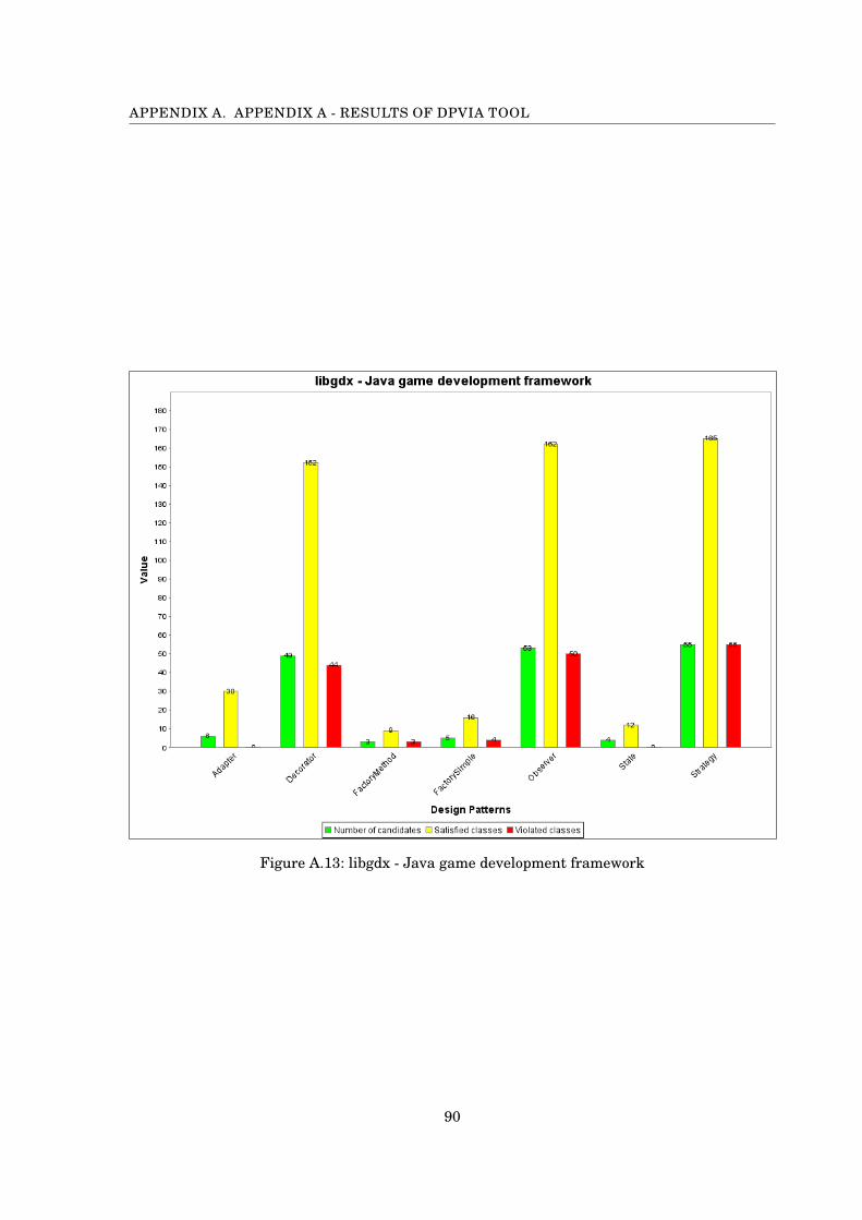
APPENDIX A. APPENDIX A - RESULTS OF DPVIA TOOL
Figure A.13: libgdx - Java game development framework
90

Figure A.14: openjms - Java Message Service
91

APPENDIX A. APPENDIX A - RESULTS OF DPVIA TOOL
Figure A.15: scarab - Issue Tracking
92

BIBLIOGRAPHY
[1] R. F. et al., “Metarole-based modeling language (rbml) specification v1. 0,” 2002.
[2] G. D. K. Quotes., “On defining the problem by albert einstein,” Accessed July 1, 2017.,
http://www.gurteen.com/gurteen/gurteen.nsf/id/L004680/.
[3] D. J.Eck, Introduction to Programming Using Java, ch. 8, pp. 373–425.
In: Hobart and William Smith Colleges„ November 2007.
[4] A. et al., “Analyzing design pattern for extensibility,” in 5th International Conference on
Information Processing, pp. 269–278, 2011.
[5] A. R. et al., Aspect-Oriented, Model-Driven Software Product Lines: The AMPLE Way, ch. 1.
Cambridge University Press, 2011.
[6] S. Burger and O. Hummel, “Towards automated design smell detection,” ICSEA2014, 2014.
[7] E. G. et al., Design Patterns: Elements of reusable object-oriented software, Addison-Wesley,
1995.
[8] C. A. et al., “A pattern language - town, buildings, construction,” Oxford University Press,
New York, 1977.
[9] A. A. et al., “A methodology to assess the impact of design patterns on software quality,”
Information Software Technology, no. 54, pp. 331–346, 2011.
[10] N.-L. H. et al., “Object-oriented design: A goal driven and pattern based approach,” Software
and Systems Modeling, Spinger, vol. 8, pp. 67–84, 2009.
[11] B. Huston, “The effects of design pattern application on metric scores,” Journal of Systems
and Software, Elsevier, vol. 58, pp. 261–269, 2001.
[12] T. Muraki and M. Saeki, “Metrics for applying gof design patterns in refactoring processes,”
ACM Proceedings of the 4th International Workshop on Principles of Software Evolution,
Vienna, Austria, pp. 27–36, 2001.
93

BIBLIOGRAPHY
[13] M. V. et al., “A controlled experiment comparing the maintainability of programs designed
with and without design patterns - a replication in a real programming environment,”
Empirical Software Engineering, Springer, vol. 9, pp. 149–195, 2003.
[14] F. K. et al., “Playing roles in design patterns: An empirical descriptive and analytic study,”
In: 25th IEEE International Conference on Software Maintenance. IEEE, pp. 83–92,
2009.
[15] A. A. et al., “The effect of gof design patterns on stability: A case study,” IEEE Trans. Softw.
Eng., no. 41, pp. 781–802, 2015.
[16] D. Riehle, “Lessons learned from using design patterns in industry projects,” In Transactions
on Pattern Languages of Programming II, Springer-Verlag, vol. LNCS 6510, pp. 1–15,
2011.
[17] D. L. Parnas, “Software aging,” ICSE ’94 Proceedings of the 16th international conference on
Software engineering, IEEE Computer Society Press Los Alamitos, CA, USA, pp. 279–287,
1994.
[18] J. M. B. et al., “Design patterns and change proneness: an examination of five evolving
systems,” Proceedings. 5th International Workshop on Enterprise Networking and Com-
puting in Healthcare Industry (IEEE Cat. No.03EX717), pp. 40–49, 2003.
[19] M. G. et al., “Design patterns and change proneness: A replication using proprietary c
software,” 2009 16th Working Conference on Reverse Engineering, Lille, pp. 160–164,
2009.
[20] N. Bautista, “A beginners guide to design patterns,” Accessed August 15, 2017., http://code.
tutsplus.com/articles/a-beginners-guide-to-design-patterns--net-12752.
[21] A. A. et al., “Research state of the art on gof design patterns: A mapping study,” Journal of
Systems and Software, Elsevier, vol. 86, no. 7, pp. 1945–1964, July 2013.
[22] A. A. et al., “Design pattern alternatives: What to do when a gof pattern fails,” Proceedings
of the 17th Panhellenic Conference on Informatics At: Thessaloniki, Greece, pp. 1–6,
September 2013.
[23] I. A. et al., “Design patterns detection based on its domain,” Information Technology (ICIT)
2017 8th International Conference, pp. 304–308, 2017.
[24] T. D. et al., “Dp-core: A design pattern detection tool for code reuse,” Proceedings of the
Sixth International Symposium on Business Modeling and Software Design (BMSD),
pp. 160–169, 2016.
94

BIBLIOGRAPHY
[25] A. D. et al., “Metrics for sustainable software architectures an industry perspective,” In ABB
Corporate Research - RA Software/SAM WICSA, 2014.
[26] C.Szyperski, “Independently extensible systems - software engineering potential and chal-
lenges,” In Proceedings of the 19th Australian Computer Science Conference, Melbourne,
Australia, 1996.
[27] M. Zenger, “Programming language abstractions for extensible software components,” In
Lausanne: Swiss Federal Institute of Technology, 2004.
[28] P. S. et al., “Reuse contracts: Managing the evolution of reusable assets,” In Conference on
Object-Oriented Programming Systems, Languages and Applications, pp. 268–285, 1996.
[29] B. B. et al., Head First Design Patterns.
In: O’Reilly Media, June 2009.
[30] J. M. et al., “Precise modeling of design patterns in uml,” Proceedings of the 26th Interna-
tional Conference on Software Engineering (ICSE’ 04), Washington, DC, USA: IEEE
Computer Society, 2004.
[31] A. Lauder and S. Kent, “Precise visual specification of design patterns,” Springer Berlin
Heidelberg, pp. 114–134, 1998.
[32] C. Izurieta and J. M. Bieman, “How software designs decay: A pilot study of pattern evolu-
tion,” First International Symposium on Empirical Software Engineering and Measure-
ment, pp. (ESEM), 459–461, 2007.
[33] C. Izurieta, “Decay and grime buildup in evolving object oriented design patterns,” Colorado
State University Fort Collins, 2009.
[34] C. Izurieta and J. M.Bieman, “A multiple case study of design pattern decay, grime, and
rot in evolving software systems,” in Software Quality Journal (2013) Springer Science+
Business Media, pp. 289–323, 2012.
[35] N. M. et al., “A taxonomy and a first study of design pattern defects,” IEEE International
Workshop on Software Technology and Engineering Practice, IEEE Computer Society,
Budapest, Hungary, pp. 225–229, 2005.
[36] M. R. Dale and C. Izurieta, “Impacts of design pattern decay on system quality,” ESEM
14 Proceedings of the 8th ACM/IEEE International Symposium on Empirical Software
Engineering and Measurement, ACM Press, New York, NY, USA, 2014.
[37] N. T. et al., “Design pattern detection using similarity scoring,” IEEE Transactions on
Software Engineering, vol. 32, no. 11, pp. 896–909, 2006.
95

BIBLIOGRAPHY
[38] V. D. B. et al., “A measure of similarity between graph vertices: Applications to synonym
extraction and web searching,” SIAM Rev., vol. 46, no. 4, pp. 647–666, 2004.
[39] “Jhotdraw start page.” http://www.jhotdraw.org/.
Accessed: 15-08-2017.
[40] “Jrefactory.” http://jrefactory.sourceforge.net/.
Accessed: 30-07-2017.
[41] “Junit 5.” http://junit.org/junit5/.
Accessed: 15-08-2017.
[42] N. Shi and R. Olsson, “Reverse engineering of design patterns from java source code,” In the
21st IEEE/ACM International Conference on Automated Software Engineering (ASE’06),
Tokyo, Japan., 2006.
[43] A. D. L. et al., “An eclipse plug-in for the detection of design pattern instances through static
and dynamic analysis,” IEEE International Conference on Software Maintenance, ICSM.,
pp. 1–6, 2010.
[44] A. D. L. et al., “Design pattern recovery through visual language parsing and source code
analysis,” Journal of Systems and Software, vol. 82, no. 7, pp. 1177–1193, 2009.
[45] A. D. L. et al., “Behavioral pattern identification through visual language parsing and code
instrumentation,” Procs. of Europ. Conference on Software Maintenance and Reengineer-
ing, Kaiserslautern, Germany, pp. 99–108, 2009.
[46] Z. et al., “On applying machine learning techniques for design pattern detection.,” Journal
of Systems and Software, vol. 103, pp. 102–117, 2015.
[47] A. et al., “A tool for design pattern detection and software architecture reconstruction,”
Information Sciences. Universita Degli Studi di Milano-Bicocca, DISCo — Dipartimento
di Informatica, Sistemistica e Comunicazione, 20126 Milan, Italy, vol. 181, no. 7, pp. 1306–
1324, 2011.
[48] A. et al., “The marple project - a tool for design pattern detection and software architecture
reconstruction,” In Proceedings of the 1st International Workshop on Academic Software
Development Tools and Techniques. Paphos, Cyprus: Software Composition Group, 2008.
[49] S. S. et al., “An automated software tool for validating design patterns,” Honolulu, 2011.
[50] D.-K. K. et al., “Using role-based modeling language (rbml) to characterize model families,”
In Eighth IEEE International Conference on Engineering of Complex Computer Systems,
2002.
96

BIBLIOGRAPHY
[51] D.-K. K. et al., “A uml-based language for specifying domain-specific patterns,” Journal of
Visual Languages Computing, vol. 15, no. 3-4, pp. 265–289, June-August 2004.
[52] D.-K. Kim and W. Shen, “Evaluating pattern conformance of uml models: a divide-and-
conquer approach and case studies,” Software Quality Journal, vol. 16, no. 3, pp. 329–359,
September 2008.
[53] “Uml lab round-trip engineering tool.” https://www.uml-lab.com/en/uml-lab/.
Accessed: 20-05-2017.
[54] “Altova umodel round-trip engineering tool.” https://www.altova.com/umodel.
Accessed: 20-05-2017.
[55] “Ibm rational software architect.” https://www.ibm.com/developerworks/downloads/r/
architect/index.html.
Accessed: 20-05-2017.
[56] T. et al., “Rules About XML in XML,” Expert Syst. Appl., vol. 30, pp. 397–411, Feb. 2006.
[57] K. et al., “A Better XML Parser through Functional Programming,” in Practical Aspects of
Declarative Languages, pp. 209–224, Springer, Berlin, Heidelberg, Jan. 2002.
[58] H. et al., “A Comparative Study and Benchmarking on XML Parsers,” in The 9th Interna-
tional Conference on Advanced Communication Technology, vol. 1, pp. 321–325, Feb.
2007.
[59] R. Giganto, “Generating class models through controlled requirements,” New Zealand
Computer Science Research Conference (NZCSRSC), Christchurch, New Zealand, 2008.
[60] G. L. et al., “A new semantic similarity measuring method based on web search engines,”
WSEAS Transaction on Computer, vol. 9, no. 1, 2010.
[61] D. Chen and C. Manning, “A fast and accurate dependency parser using neural networks,”
Proceedings of EMNLP, 2014.
[62] R. S. et al., “Parsing with compositional vector grammars,” Proceedings of ACL, 2013.
[63] “Word net 2.1.” https://wordnet.princeton.edu/wordnet/download/.
Accessed: 01-08-2017.
[64] S. K. et al., “Automated analysis of natural language properties for uml models,” Software
Engineering and Network Systems Laboratory, Michigan State University, 2010.
[65] P. More and R. Phalnikar, “Generating uml diagrams from natural language specifications,”
International Journal of Applied Information Systems, Foundation of Computer Science,
vol. 1, no. 8, 2012.
97

BIBLIOGRAPHY
[66] M. et al., “The stanford corenlp natural language processing toolkit,” In Proceedings of
the 52nd Annual Meeting of the Association for Computational Linguistics: System
Demonstrations, pp. 55–60, 2014.
[67] E. Loper and S. Bird, “Nltk: the natural language toolkit,” In ETMTNLP ’02 Proceedings of
the ACL-02 Workshop on Effective tools and methodologies for teaching natural language
processing and computational linguistics, vol. 1, pp. 63–70, 2002.
[68] R. S. Pressman, Software Engineering: A Practitioners Approach.
7th Edition, McGraw-Hill Publishing Company, 2010.
[69] P. Yalla and N. Sharma, “Combining natural language processing and software engineering,”
In Proc. International Conference in Recent Trends in Engineering Sciences (ICRTES),
Elsevier Conference Proceedings CPS, 2014.
[70] M. et al., “The stanford corenlp natural language processing toolkit,” in Proceedings of
the 52nd Annual Meeting of the Association for Computational Linguistics: System
Demonstrations, pp. 55–60, 2014.
[71] A. B. et al., “Generalized hamming distance,” Kluwer Academic Publishers, vol. 5, no. 4,
pp. 353–375, 2002.
[72] G. A. et al., “Leveraging linguistic structure for open domain information extraction,” In
Proceedings of the Association of Computational Linguistics (ACL), 2015.
[73] C. et al., “Experimentation in software engineering,” Springer Berlin Heidelberg, Berlin,
Heidelberg, 2012.
98