ENHANCEMENT OF POWER QUALITY USING MC -DPFC …. Electrical - IJEEER... · [email protected]...
12
www.tjprc.org [email protected] ENHANCEMENT OF POWER QUALITY USING MC-DPFC IN TRANSMISSION SYSTEM D. RAMA CHADRA RAO 1 , K. B. MADHU SAHU 2 , CH. KRISHNA RAO 3 & K. B. SAIKIRAN 4 1 P.G.Student, Department of EEE, AITAM Engineering College, AP, India 2 Professor, Principal, Department of EEE, AITAM Engineering college, AP, India 3Associate Professor, Department of EEE, AITAM Engineering college, AP, India 4 Student, Department of EE, IIT Patna, Bihar, India ABSTRACT The Power Quality problems during the last two decades have been the major concern of the power consumer’s point of view. The operation of power systems has become complex due to growing consumption of electric power and increase in number of non-linear loads. A new device within the flexible AC-transmission system (FACTS) family, named multi connected-Distributed Power-flow controller (MC-DPFC) is presented in this paper. MC-DPFC is obtained from the distributed power flow controller (DPFC) which is derived from unified power-flow controller (UPFC). DPFC can be considered as a UPFC with elimination of common dc link between the shunt and series controllers. The active power exchange between the shunt and series converters is done by the transmission line at third harmonic frequency in MC-DPFC where as in UPFC this is done by common DC link. The MC-DPFC function is similar to that of UPFC with several low power series converters where as UPFC consists of one series converter. Therefore, MC-DPFC includes multiple series converters and one shunt converter without common dc link to improve power quality. This automatically enables the MC-DPFC to full control on all the power system parameters and also increases the reliability of the device and reduces its cost simultaneously. In this paper the power quality issues like voltage sag, voltage swell, harmonics and LLL-G fault are considered and the issues are reduced and fault is cleared which enhances the power quality. The application of MC-DPFC in power quality enhancement is simulated in Matlab/ Simulink environment which show the effectiveness of the proposed structure. KEYWORDS: FACTS (Flexible Ac-Transmission Systems), MC-DPFC (Multi Connected- Distributed Power Flow Converter), UPFC (Unified Power Flow Controller), Voltage Sag, Voltage Swell, Harmonics, LLL-G (Three Phase to Line) Fault, Power Quality Received: Sep 06, 2016; Accepted: Oct 07, 2016; Published: Oct 20, 2016; Paper Id.: IJEEERDEC20161 INTRODUCTION Now-a-days use of electric power increases day by day because of increase in electric customers. This development in electric utility encourages the entry of power quality issues in the power systems. From the customer point of view, the power quality issue is concerned about current, voltage or frequency deviation which leads to power failure. The power quality issues are solved by using flexible ac transmission systems (FACTS) [1] and custom power devices [2] which are used in transmission and distribution systems respectively. The flexible ac transmission systems (FACTS) technology performs more accurate in transmission systems which are one of the Original Article International Journal of Electrical and Electronics Engineering Research (IJEEER) ISSN(P): 2250-155X; ISSN(E): 2278-943X Vol. 6, Issue 6, Dec 2016, 1-12 © TJPRC Pvt. Ltd
-
Upload
vuongtuyen -
Category
Documents
-
view
216 -
download
2
Transcript of ENHANCEMENT OF POWER QUALITY USING MC -DPFC …. Electrical - IJEEER... · [email protected]...
www.tjprc.org [email protected]
ENHANCEMENT OF POWER QUALITY USING MC-DPFC IN TRANSMISSION
SYSTEM
D. RAMA CHADRA RAO1, K. B. MADHU SAHU2, CH. KRISHNA RAO3 & K. B. SAIKIRAN4
1P.G.Student, Department of EEE, AITAM Engineering College, AP, India 2Professor, Principal, Department of EEE, AITAM Engineering college, AP, India
3Associate Professor, Department of EEE, AITAM Engineering college, AP, India 4Student, Department of EE, IIT Patna, Bihar, India
ABSTRACT
The Power Quality problems during the last two decades have been the major concern of the power
consumer’s point of view. The operation of power systems has become complex due to growing consumption of electric
power and increase in number of non-linear loads. A new device within the flexible AC-transmission system (FACTS)
family, named multi connected-Distributed Power-flow controller (MC-DPFC) is presented in this paper. MC-DPFC is
obtained from the distributed power flow controller (DPFC) which is derived from unified power-flow controller
(UPFC). DPFC can be considered as a UPFC with elimination of common dc link between the shunt and series
controllers. The active power exchange between the shunt and series converters is done by the transmission line at
third harmonic frequency in MC-DPFC where as in UPFC this is done by common DC link. The MC-DPFC function
is similar to that of UPFC with several low power series converters where as UPFC consists of one series converter.
Therefore, MC-DPFC includes multiple series converters and one shunt converter without common dc link to improve
power quality. This automatically enables the MC-DPFC to full control on all the power system parameters and also
increases the reliability of the device and reduces its cost simultaneously. In this paper the power quality issues like
voltage sag, voltage swell, harmonics and LLL-G fault are considered and the issues are reduced and fault is cleared
which enhances the power quality. The application of MC-DPFC in power quality enhancement is simulated in
Matlab/ Simulink environment which show the effectiveness of the proposed structure.
KEYWORDS: FACTS (Flexible Ac-Transmission Systems), MC-DPFC (Multi Connected- Distributed Power Flow
Converter), UPFC (Unified Power Flow Controller), Voltage Sag, Voltage Swell, Harmonics, LLL-G
(Three Phase to Line) Fault, Power Quality
Received: Sep 06, 2016; Accepted: Oct 07, 2016; Published: Oct 20, 2016; Paper Id.: IJEEERDEC20161
INTRODUCTION
Now-a-days use of electric power increases day by day because of increase in electric customers. This
development in electric utility encourages the entry of power quality issues in the power systems. From the
customer point of view, the power quality issue is concerned about current, voltage or frequency deviation which
leads to power failure. The power quality issues are solved by using flexible ac transmission systems (FACTS) [1]
and custom power devices [2] which are used in transmission and distribution systems respectively. The flexible ac
transmission systems (FACTS) technology performs more accurate in transmission systems which are one of the
Original A
rticle
International Journal of Electrical and Electronics Engineering Research (IJEEER) ISSN(P): 2250-155X; ISSN(E): 2278-943X Vol. 6, Issue 6, Dec 2016, 1-12 © TJPRC Pvt. Ltd
2 D. Rama Chadra Rao, K. B. Madhu Sahu, Ch. Krishna Rao & K. B. Saikiran
Impact Factor (JCC): 6.1843 NAAS Rating: 2.40
applications of power electronics. The use of this technology is to control and regulate the electric variables in the power
systems.
These FACTS devices are of two types. One is Thyristor controlled devices and other is Voltage source
converters (VSC). The voltage source converters are of series, shunt, series-series and series-shunt controllers. The series
controllers consists of Dynamic Voltage Restorer(DVR), Static Synchronous Series Compensator (SSSC) and these
devices inject reactive voltage into the transmission line. The shunt controllers includes Static Compensator(STATCOM)
and this injects reactive current into the transmission line. The series-series controllers consists of Interline Power Flow
Controller(IPFC), Interline Power Quality Conditioner(IPQC) and the series-shunt controller consists of unified power
quality conditioner (UPQC) & unified power flow controller (UPFC).
The unified power flow controller (UPFC) is a versatile device which is able to control the active and reactive
power respectively and also control the voltage at the connection node [3]. The unified power flow controller (UPFC) is
modelled by the combination of SSSC, STATCOM & a common dc link to allow the flow of active power between the
series output terminals of the SSSC and the shunt output terminals of the STATCOM in both the directions.
Due to the high cost and the susceptibility to failures the UPFC is not widely applied in practice. The distributed
power flow controller (DPFC) is able to control system parameters like line impedance, transmission angle and bus
voltage like UPFC. The common DC link between the shunt and series converters was eliminated in DPFC.
The exchange of active power between the shunt and series converters is through the transmission line at the
third-harmonic frequency [4].
Figure 1: Flow Chart of DPFC from UPFC
The DPFC has the following advantages like: (1) the low voltage isolation and the low component rating of the
series converters leads to low cost. (2) The redundancy of the series converters and high control capability leads to high
reliability of the DPFC system. The power oscillation damping, voltage sag restoration or balancing asymmetry which
leads to system stability and the power quality also improved by using the DPFC system. The DPFC system structure is
having similar configuration to UPFC structure. The DPFC system consists of a single shunt controller and multiple
independent series converters which are used to balance the line parameters, such as line impedance, transmission angle
and bus voltage magnitude.
DPFC STRUCTURE
In the DPFC system, the transmission line is used as a connection between shunt converter output and AC port
of series converters, instead of using DC link for power exchange between converters. The series converter employs the
DSSC concept, which uses multiple single-phase converters instead of one three phase converter. Each converter within
the DPFC is independent and has its own DC capacitor to provide the required DC voltage, while the shunt converter is
Enhancement of Power Quality Using Mc-DPFC in Transmission System 3
www.tjprc.org [email protected]
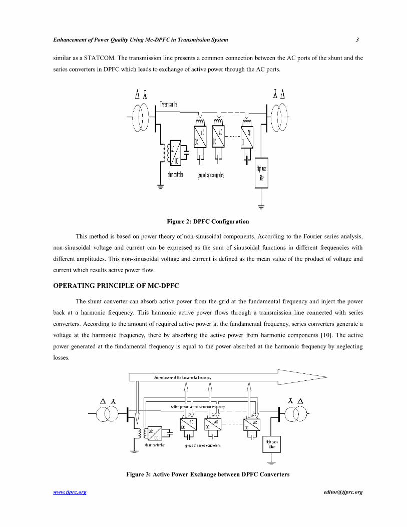
similar as a STATCOM. The transmission line presents a common connection between the AC ports of the shunt and the
series converters in DPFC which leads to exchange of active power through the AC ports.
Figure 2: DPFC Configuration
This method is based on power theory of non-sinusoidal components. According to the Fourier series analysis,
non-sinusoidal voltage and current can be expressed as the sum of sinusoidal functions in different frequencies with
different amplitudes. This non-sinusoidal voltage and current is defined as the mean value of the product of voltage and
current which results active power flow.
OPERATING PRINCIPLE OF MC-DPFC
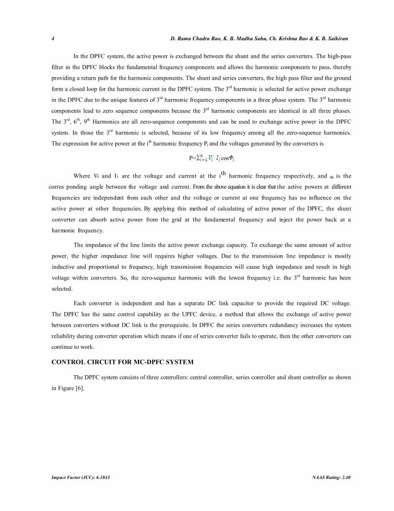
The shunt converter can absorb active power from the grid at the fundamental frequency and inject the power
back at a harmonic frequency. This harmonic active power flows through a transmission line connected with series
converters. According to the amount of required active power at the fundamental frequency, series converters generate a
voltage at the harmonic frequency, there by absorbing the active power from harmonic components [10]. The active
power generated at the fundamental frequency is equal to the power absorbed at the harmonic frequency by neglecting
losses.
Figure 3: Active Power Exchange between DPFC Converters
4 D. Rama Chadra Rao, K. B. Madhu Sahu, Ch. Krishna Rao & K. B. Saikiran
Impact Factor (JCC): 6.1843 NAAS Rating: 2.40
In the DPFC system, the active power is exchanged between the shunt and the series converters. The high-pass
filter in the DPFC blocks the fundamental frequency components and allows the harmonic components to pass, thereby
providing a return path for the harmonic components. The shunt and series converters, the high pass filter and the ground
form a closed loop for the harmonic current in the DPFC system. The 3rd harmonic is selected for active power exchange
in the DPFC due to the unique features of 3rd harmonic frequency components in a three phase system. The 3rd harmonic
components lead to zero sequence components because the 3rd harmonic components are identical in all three phases.
The 3rd, 6th, 9th Harmonics are all zero-sequence components and can be used to exchange active power in the DPFC
system. In those the 3rd harmonic is selected, because of its low frequency among all the zero-sequence harmonics.
The expression for active power at the ith harmonic frequency Pi and the voltages generated by the converters is
P= cos
Where Vi and Ii are the voltage and current at the ith harmonic frequency respectively, and Φi is the
corres ponding angle between the voltage and current. From the above equation it is clear that the active powers at different
frequencies are independent from each other and the voltage or current at one frequency has no influence on the
active power at other frequencies. By applying this method of calculating of active power of the DPFC, the shunt
converter can absorb active power from the grid at the fundamental frequency and inject the power back at a
harmonic frequency.
The impedance of the line limits the active power exchange capacity. To exchange the same amount of active
power, the higher impedance line will requires higher voltages. Due to the transmission line impedance is mostly
inductive and proportional to frequency, high transmission frequencies will cause high impedance and result in high
voltage within converters. So, the zero-sequence harmonic with the lowest frequency i.e. the 3rd harmonic has been
selected.
Each converter is independent and has a separate DC link capacitor to provide the required DC voltage.
The DPFC has the same control capability as the UPFC device, a method that allows the exchange of active power
between converters without DC link is the prerequisite. In DPFC the series converters redundancy increases the system
reliability during converter operation which means if one of series converter fails to operate, then the other converters can
continue to work.
CONTROL CIRCUIT FOR MC-DPFC SYSTEM
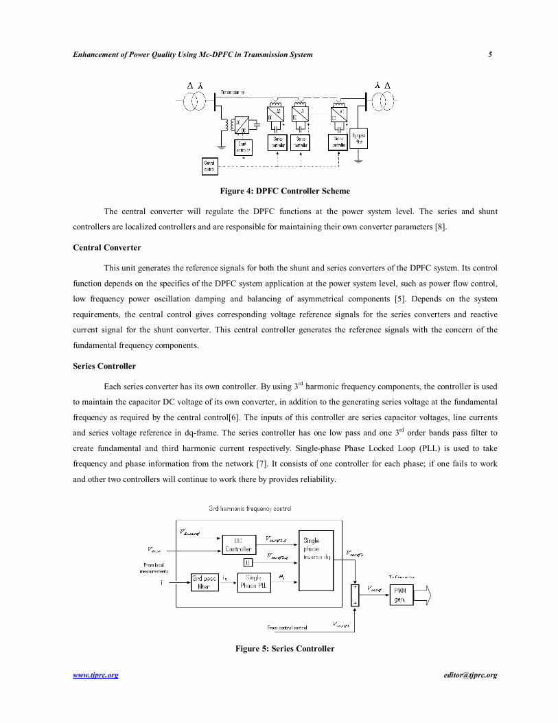
The DPFC system consists of three controllers: central controller, series controller and shunt controller as shown
in Figure [6].
Enhancement of Power Quality Using Mc-DPFC in Transmission System 5
www.tjprc.org [email protected]
Figure 4: DPFC Controller Scheme
The central converter will regulate the DPFC functions at the power system level. The series and shunt
controllers are localized controllers and are responsible for maintaining their own converter parameters [8].
Central Converter
This unit generates the reference signals for both the shunt and series converters of the DPFC system. Its control
function depends on the specifics of the DPFC system application at the power system level, such as power flow control,
low frequency power oscillation damping and balancing of asymmetrical components [5]. Depends on the system
requirements, the central control gives corresponding voltage reference signals for the series converters and reactive
current signal for the shunt converter. This central controller generates the reference signals with the concern of the
fundamental frequency components.
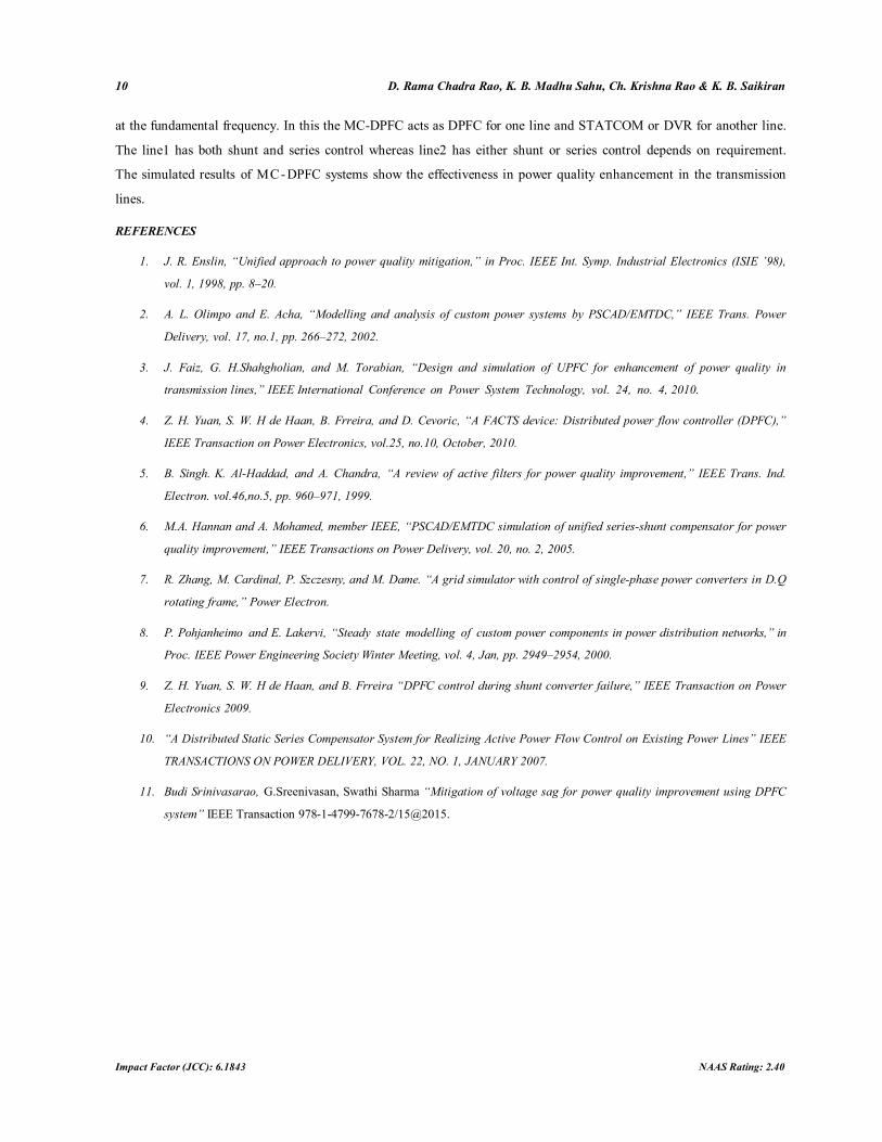
Series Controller
Each series converter has its own controller. By using 3rd harmonic frequency components, the controller is used
to maintain the capacitor DC voltage of its own converter, in addition to the generating series voltage at the fundamental
frequency as required by the central control[6]. The inputs of this controller are series capacitor voltages, line currents
and series voltage reference in dq-frame. The series controller has one low pass and one 3rd order bands pass filter to
create fundamental and third harmonic current respectively. Single-phase Phase Locked Loop (PLL) is used to take
frequency and phase information from the network [7]. It consists of one controller for each phase; if one fails to work
and other two controllers will continue to work there by provides reliability.
Figure 5: Series Controller

6 D. Rama Chadra Rao, K. B. Madhu Sahu, Ch. Krishna Rao & K. B. Saikiran
Impact Factor (JCC): 6.1843 NAAS Rating: 2.40
The working of series controller is like DVR (Dynamic voltage restorer) in transmission lines i.e. it controls the
voltage in the transmission lines. If voltage swell occurs in the line, it injects the voltage into the line whereas voltage
swell occurs in the line then it absorbs the voltage and stored in a capacitor which is useful whenever the sag condition
appears.
Shunt Controller
The purpose of this unit is to inject a constant 3rd harmonic current into the line to supply active power for the
series converters. It maintains the capacitor DC voltage of the shunt converter at a constant value by absorbing active
power from the grid at the fundamental frequency and injecting the required reactive current at the fundamental
frequency at the grid.
Figure 6: Shunt Controller
The shunt connected STATCOM with battery energy storage is connected at the PCC in the grid system with
the non-linear load. The STATCOM compensator output is varies depends on the controlled strategy, so as to maintain
the power quality norms in the grid system [9]. The current control strategy is obtained from the controller which defines
the functional operation of the STATCOM compensator in the power system. A single STATCOM using insulated gate
bipolar transistor is proposed to have a reactive power support to the DPFC system.
SIMULATION RESULTS
The case study, sag and swell conditions are implemented in single machine infinite bus system and analysed
results are as follows [8]. The voltage sag and voltage swell are created to analyse the performance of the MC- DPFC
system in line 1, as shown in Figure 7. The voltage sag is created for duration of 0.1 seconds (100-200 ms) and the
voltage swell is created for duration of 0.1 seconds (200-300ms).

Enhancement of Power Quality Using Mc-DPFC in Transmission System 7
www.tjprc.org [email protected]
0 0.05 0.1 0.15 0.2 0.25 0.3 0.35 0.4 0.45 0.5-600
-400
-200
0
200
400
600
Time in seconds
Vol
tage
in v
olts
Voltage wave form with sag and swell conditions
Figure 7: Voltages Sag and Swell Conditions in Line1 before Control
The MC-DPFC can compensate the load voltage sag and swell effectively. The mitigation with MC-DPFC [11]
is shown in Figure 8 for line 1.
0 0.05 0.1 0.15 0.2 0.25 0.3 0.35 0.4 0.45 0.5-500
-400
-300
-200
-100
0
100
200
300
400
500
Time in seconds
Vol
tage
in v
olts
Load voltage waveform
Figure 8: Load Voltage after Using DPFC System for Line 1
The load voltage harmonic analysis, using Fast Fourier transform (FFT) of power GUI window by Simulink, as
shown in Figure 9. It can be seen, after MC-DPFC implementation in system, the odd harmonics are reduced within
acceptable limits and total harmonic distortion (THD) of load voltage is minimized in line1.

8 D. Rama Chadra Rao, K. B. Madhu Sahu, Ch. Krishna Rao & K. B. Saikiran
Impact Factor (JCC): 6.1843 NAAS Rating: 2.40
0 0.1 0.2 0.3 0.4 0.5-400
-200
0
200
400Selected signal: 25 cycles. FFT window (in red): 1 cycles
Time (s)
0 200 400 600 800 10000
0.002
0.004
0.006
0.008
0.01
Frequency (Hz)
Fundamental (50Hz) = 420 , THD= 0.41%
Mag
(% o
f Fun
dam
enta
l)
Figure 9: THD Performance of Load Voltage in Line 1
In the same way, the voltage sag, voltage swell and fault are created to analyse the performance of the
MC-DPFC system in line 2, as shown in Figure 10. The voltage sag is created for duration of 0.1 seconds (100-200 ms)
and the voltage swell is created for duration of 0.1 seconds (200-300ms) and the fault is created for duration of 0.1
seconds (300-400ms). The MC-DPFC compensates all these power quality issues effectively and the mitigated voltage is
shown in figure 11.
0 0.05 0.1 0.15 0.2 0.25 0.3 0.35 0.4 0.45 0.5-0.8
-0.6
-0.4
-0.2
0
0.2
0.4
0.6
Time in seconds
volta
ge in
kilo
volts
volatage waveform in line 2
Figure 10: Voltage in Line2 before Control
0 0.05 0.1 0.15 0.2 0.25 0.3 0.35 0.4 0.45 0.5-500
-400
-300
-200
-100
0
100
200
300
400
500
Time in seconds
Voltage in
volts
load voltage waveform at line2
Figure 11: Load Voltage after Using DPFC System for Line2

Enhancement of Power Quality Using Mc-DPFC in Transmission System 9
www.tjprc.org [email protected]
The load voltage harmonic analysis, using Fast Fourier transform (FFT) of power GUI window by Simulink, as
shown in Figure 12. It can be seen, after MC-DPFC implementation in system, the odd harmonics are reduced within
acceptable limits and total harmonic distortion (THD) of load voltage is minimized in line2.
0 0.1 0.2 0.3 0.4 0.5-400
-200
0
200
400Selected signal: 25 cycles. FFT window (in red): 1 cycles
Time (s)
0 200 400 600 800 10000
0.2
0.4
0.6
0.8
1
1.2
Frequency (Hz)
Fundamental (50Hz) = 422.7 , THD= 6.75%
Mag
(% o
f Fun
dam
enta
l)
Figure 12: THD Performance of Load Voltage in Line2
The MC-DPFC system can mitigate all the power quality issues in both the lines. The FFT analysis is also done
to the load voltages in both the lines. This type system is used in substations where more than one generating station is
held, for example one substation has both wind and hydro power as sources respectively. The first line transmits wind
power i.e. non conventional source energy which needs full control whereas the second line transmits the hydro power i.e.
conventional source of energy which needs moderate control. So the MC-DPFC acts as DPFC for line1 whereas it acts as
STATCOM for line2. Here the simulation system parameters are mentioned.
Table 1: Simulation System Parameters
Parameters Values Rated Voltage 25kV Rated Power/Frequency 250 MVA/ 50 HZ Transmission line inductance 0.06 p.u.
Type of Fault ABC-G(LLL-G FAULT) Ground Resistance 0.01 Ω Fault resistance 0.01 Ω
CONCLUSIONS
In this paper, enhancement of power quality issues like voltage sag and swell, harmonics and fault conditions
are simulated in Matlab/Simulink environment employing a new FACTS device named M u l t i
c o n n e c t e d - Distributed Power Flow Controller (MC-DPFC). The MC-DPFC is emerged from the UPFC and
inherits the control capability of the UPFC, which is the simultaneous adjustment of the line voltage magnitude.
The series converter of the DPFC employs the D-FACTS concept, which uses multiple small single phase converters
instead of one large size converter. It is proved that the shunt and series converters in the MC-DPFC can exchange active
power at the third harmonic frequency, and the series converters are able to inject controllable active and reactive power
10 D. Rama Chadra Rao, K. B. Madhu Sahu, Ch. Krishna Rao & K. B. Saikiran
Impact Factor (JCC): 6.1843 NAAS Rating: 2.40
at the fundamental frequency. In this the MC-DPFC acts as DPFC for one line and STATCOM or DVR for another line.
The line1 has both shunt and series control whereas line2 has either shunt or series control depends on requirement.
The simulated results of MC-DPFC systems show the effectiveness in power quality enhancement in the transmission
lines.
REFERENCES
1. J. R. Enslin, “Unified approach to power quality mitigation,” in Proc. IEEE Int. Symp. Industrial Electronics (ISIE ’98),
vol. 1, 1998, pp. 8–20.
2. A. L. Olimpo and E. Acha, “Modelling and analysis of custom power systems by PSCAD/EMTDC,” IEEE Trans. Power
Delivery, vol. 17, no.1, pp. 266–272, 2002.
3. J. Faiz, G. H.Shahgholian, and M. Torabian, “Design and simulation of UPFC for enhancement of power quality in
transmission lines,” IEEE International Conference on Power System Technology, vol. 24, no. 4, 2010.
4. Z. H. Yuan, S. W. H de Haan, B. Frreira, and D. Cevoric, “A FACTS device: Distributed power flow controller (DPFC),”
IEEE Transaction on Power Electronics, vol.25, no.10, October, 2010.
5. B. Singh. K. Al-Haddad, and A. Chandra, “A review of active filters for power quality improvement,” IEEE Trans. Ind.
Electron. vol.46,no.5, pp. 960–971, 1999.
6. M.A. Hannan and A. Mohamed, member IEEE, “PSCAD/EMTDC simulation of unified series-shunt compensator for power
quality improvement,” IEEE Transactions on Power Delivery, vol. 20, no. 2, 2005.
7. R. Zhang, M. Cardinal, P. Szczesny, and M. Dame. “A grid simulator with control of single-phase power converters in D.Q
rotating frame,” Power Electron.
8. P. Pohjanheimo and E. Lakervi, “Steady state modelling of custom power components in power distribution networks,” in
Proc. IEEE Power Engineering Society Winter Meeting, vol. 4, Jan, pp. 2949–2954, 2000.
9. Z. H. Yuan, S. W. H de Haan, and B. Frreira “DPFC control during shunt converter failure,” IEEE Transaction on Power
Electronics 2009.
10. “A Distributed Static Series Compensator System for Realizing Active Power Flow Control on Existing Power Lines” IEEE
TRANSACTIONS ON POWER DELIVERY, VOL. 22, NO. 1, JANUARY 2007.
11. Budi Srinivasarao, G.Sreenivasan, Swathi Sharma “Mitigation of voltage sag for power quality improvement using DPFC
system” IEEE Transaction 978-1-4799-7678-2/15@2015.
Enhancement of Power Quality Using Mc-DPFC in Transmission System 11
www.tjprc.org [email protected]
AUTHORS DETAILS
Mr. D. Rama Chadra Rao received his B.Tech Degree in Electrical & Electronics Engineering from Godavari
institute of engineering and technology, Rajahmundry, East Godavari, A.P, and India in 2014. Currently pursuing his
M.Tech Degree in Aditya Institute of Technology & Management, Tekkali, Srikakulam, India. His research interests are
Power electronics and Drives and Power systems.
Dr. K. B. Madhu Sahu received the B. E. Degree in Electrical Engineering from college of Engineering.
Gandhi Institute of Technology & Management, Visakhapatnam, India in 1985 and the M. E Degree in Power systems
from college of Engineering, Andhra University and Visakhapatnam in 1998. He obtained his Ph. D from Jawaharlal
Nehru Technological University, Hyderabad. He has 27 years of Experience. Currently he is working as a Professor &
Principal in the Department of Electrical & Electronics Engineering, AITAM, Tekkali, and Srikakulam, Andhra Pradesh.
His research interests include Gas Insulated Substations, High Voltage Engineering and Power Systems. He has published
research papers in National and International conferences.
Sri. CH. Krishna Rao obtained B.Tech Degree in Electrical and Electronics Engineering from College of
Engineering, GMRIT Rajam and Srikakulam Dt. He also obtained M.Tech in Power Electronics and Electric Drives from
ASTIET Garividi, Vizianagaram. He has 13 Years of Teaching Experience. Presently he is working as Associate
Professor in the Department of Electrical & Electronics Engineering, AITAM, Tekkali, and Srikakulam, Andhra
Pradesh. He has published number of papers in journals, National and International conferences. His main areas of

12 D. Rama Chadra Rao, K. B. Madhu Sahu, Ch. Krishna Rao & K. B. Saikiran
Impact Factor (JCC): 6.1843 NAAS Rating: 2.40
interest are Power Electronics, Switched Mode Power Supplies, Electrical drives and Renewable energy sources.
Mr. K.B. SaiKiran received his B. Tech degree in Electrical Engineering from Indian institute of technology,
Patna, Bihar and India in 2016. His research interests are Power Systems and Power electronics and Drives.


![Deciding optimal location for placing FACTS devices [UPFC, IPQC, DPFC] using Bang-Bang control technique](https://static.fdocuments.in/doc/165x107/577cc8811a28aba711a300aa/deciding-optimal-location-for-placing-facts-devices-upfc-ipqc-dpfc-using.jpg)