ENHANCEMENT OF FLOW-JET COMBINED BOILING HEAT TRANSFER … · made progress on the boiling heat...
15
Journal of Enhanced Heat Transfer, 19 (6): 489–503 (2012) ENHANCEMENT OF FLOW-JET COMBINED BOILING HEAT TRANSFER OF FC-72 OVER MICRO-PIN-FINNED SURFACES Yonghai Zhang, 1 Jinjia Wei, 1,* & Dong Guo 2 1 State Key Laboratory of Multiphase Flow in Power Engineering, Xi’an Jiaotong University, Xi’an, 710049, China 2 YanTai WanHua Group, YanTai, 264000, China ∗ Address all correspondence to Jinjia Wei E-mail: [email protected] For highly efficient solving of the power dissipation problem of electronic components with high heat flux, experimental study of the flow-jet combined boiling heat transfer on silicon chips was conducted. Micro-pin-fins with dimensions of 30×60 μm 2 and 30×120 μm 2 (thickness × height) were fabricated on the chip surfaces by the dry etching technique. The experiments were made at three different cross-flow velocities Vc (0.5, 1.0, 1.5 m/s) and different jet velocities Vj (0–2 m/s) with two liquid subcooling ∆T sub (25 ◦ C and 35 ◦ C). A smooth surface was also tested for comparison. The micro-pin-fins showed a considerable heat transfer enhancement due to an increase in effective heat transfer surface area caused by micro-convection around micro-pin-fins. The maximum allowable heat flux qmax is increased and the wall superheat is decreased greatly. For a given V c , the heat transfer enhancement is more significant as V j increases, but the qmax increment decreases as Vc increases. The fin efficiency decreases as Vc or/and Vj increases or the heat flux q increases. The maximum q max can reach 161 W/cm 2 at V c = 1.5 m/s, V j = 2 m/s, ∆T sub = 35 ◦ C for chip PF30-120. KEY WORDS: heat transfer enhancement, micro-pin-fin, flow boiling, jet impingement, FC-72 1. INTRODUCTION Since the development of the first electronic digital com- puters in the 1940s, removal of heat has played a key role in ensuring the reliable operation of successive genera- tions of computers. With the development of microelec- tromechanical system (MEMS) technology, a high inte- gration density and frequency of electronic circuit make the power dissipation an increasingly serious problem. Direct liquid cooling, such as liquid flow, jet impinge- ment, etc., has been considered as one of the promising schemes. Boiling heat transfer with phase change by di- electric liquid gives an enhancement of electronic com- ponent cooling compared with single-phase heat transfer. Treated surfaces have also been found to show a great po- tential in enhancing the boiling heat transfer process. As another local cooling technique, jet impingement is much more efficient due to the decrease of boundary layer by the high velocity impact. Compatibility between the coolant and the specific system is first required, es- pecially for insulation property. A low boiling point and large contact angle for dielectric liquid is quite suitable for cooling electronic components, such as liquid nitro- gen, FC series (Fabbri et al., 2006, 2003), and so on, which can achieve higher heat flux than air coolant. Ac- cordingly, IBM sponsored a number of studies to investi- gate liquid jet impingement heat transfer with and with- out boiling. One of the earliest studies was conducted by Ma and Bergles (1983), who investigated boiling jet im- pingement of R-113 on a simulated 5 mm × 5 mm mi- croelectronic chip. The achievement of heat fluxes up to 10 6 W/m 2 was reported. As the nanotechnology devel- ops, nanofluids can also increase the nucleate sites and improve the critical heat flux, but they inhibits the nucle- ate boiling intension due to the nanoparticle sorption layer on the surface. Nguyen et al. (2009) considered that there was an optimal combination of the distance of nozzle-to- surface and the volume fraction. Parameters such as jet 1065-5131/12/$35.00 c ⃝ 2012 by Begell House, Inc. 489
Transcript of ENHANCEMENT OF FLOW-JET COMBINED BOILING HEAT TRANSFER … · made progress on the boiling heat...
Journal of Enhanced Heat Transfer, 19 (6): 489–503 (2012)
ENHANCEMENT OF FLOW-JET COMBINED BOILINGHEAT TRANSFER OF FC-72 OVER MICRO-PIN-FINNEDSURFACES
Yonghai Zhang,1 Jinjia Wei,1,∗ & Dong Guo2
1State Key Laboratory of Multiphase Flow in Power Engineering, Xi’an Jiaotong University,Xi’an, 710049, China2YanTai WanHua Group, YanTai, 264000, China
∗Address all correspondence to Jinjia Wei E-mail: [email protected]
For highly efficient solving of the power dissipation problem of electronic components with high heat flux, experimentalstudy of the flow-jet combined boiling heat transfer on silicon chips was conducted. Micro-pin-fins with dimensions of30×60 µm2 and 30×120 µm2 (thickness × height) were fabricated on the chip surfaces by the dry etching technique.The experiments were made at three different cross-flow velocities Vc (0.5, 1.0, 1.5 m/s) and different jet velocities Vj
(0–2 m/s) with two liquid subcooling ∆Tsub (25◦C and 35◦C). A smooth surface was also tested for comparison. Themicro-pin-fins showed a considerable heat transfer enhancement due to an increase in effective heat transfer surface areacaused by micro-convection around micro-pin-fins. The maximum allowable heat flux qmax is increased and the wallsuperheat is decreased greatly. For a given Vc, the heat transfer enhancement is more significant as Vj increases, butthe qmax increment decreases as Vc increases. The fin efficiency decreases as Vc or/and Vj increases or the heat flux qincreases. The maximum qmax can reach 161 W/cm2 at Vc = 1.5 m/s, Vj = 2 m/s, ∆Tsub = 35◦C for chip PF30-120.
KEY WORDS: heat transfer enhancement, micro-pin-fin, flow boiling, jet impingement, FC-72
1. INTRODUCTION
Since the development of the first electronic digital com-puters in the 1940s, removal of heat has played a key rolein ensuring the reliable operation of successive genera-tions of computers. With the development of microelec-tromechanical system (MEMS) technology, a high inte-gration density and frequency of electronic circuit makethe power dissipation an increasingly serious problem.Direct liquid cooling, such as liquid flow, jet impinge-ment, etc., has been considered as one of the promisingschemes. Boiling heat transfer with phase change by di-electric liquid gives an enhancement of electronic com-ponent cooling compared with single-phase heat transfer.Treated surfaces have also been found to show a great po-tential in enhancing the boiling heat transfer process.
As another local cooling technique, jet impingementis much more efficient due to the decrease of boundarylayer by the high velocity impact. Compatibility between
the coolant and the specific system is first required, es-pecially for insulation property. A low boiling point andlarge contact angle for dielectric liquid is quite suitablefor cooling electronic components, such as liquid nitro-gen, FC series (Fabbri et al., 2006, 2003), and so on,which can achieve higher heat flux than air coolant. Ac-cordingly, IBM sponsored a number of studies to investi-gate liquid jet impingement heat transfer with and with-out boiling. One of the earliest studies was conducted byMa and Bergles (1983), who investigated boiling jet im-pingement of R-113 on a simulated 5 mm× 5 mm mi-croelectronic chip. The achievement of heat fluxes up to106 W/m2 was reported. As the nanotechnology devel-ops, nanofluids can also increase the nucleate sites andimprove the critical heat flux, but they inhibits the nucle-ate boiling intension due to the nanoparticle sorption layeron the surface. Nguyen et al. (2009) considered that therewas an optimal combination of the distance of nozzle-to-surface and the volume fraction. Parameters such as jet
1065-5131/12/$35.00 c⃝ 2012 by Begell House, Inc. 489
490 Zhang, Wei, & Guo
NOMENCLATURE
A chip surface area, cm2 Z nozzle–surface distance, mD jet diameter, mh fin height,µm Greek Symbolshv heat transfer coefficient, ∆Tb wall superheat,Tw − Tb, ◦C
W/(cm−2.◦C) ∆Tsat wall superheat,Tw − Tsat, ◦Cm m = (2hv/λt)−0.5,λ = 0.25, m−1 ∆Tsub liquid subcooling,Tsat − Tb, ◦Cp fin pitch,µm ηf fin efficiencyq heat flux, W/cm2
qCHF critical heat flux, W/cm2 Subscriptsqmax maximum allowable heat flux, W/cm2 b bulkr impinging radius, m c cross flowR jet-cross-flow velocity ratio CHF critical heat fluxt fin thickness,µm F finTb bulk liquid temperature,◦C j jetTsat boiling temperature,◦C max maximumTw wall temperature,◦C sat saturatedVc cross-flow velocity, m/s sub subcooledVj jet velocity, m/s w wall
velocity (Vj), jet diameterD, nozzle-to-surface distanceZ/D, configuration (jet array, impinging surface struc-ture), etc. are needed to be optimized for enhancement.Jiji and Dagan (1998) investigated single-phase free liq-uid jet impingement on a single heat source 2× 2, and3 × 3 arrays of heat sources. In addition, tests were con-ducted for 1, 4, and 9 jets per heat source. The resultsindicated that thermal resistance with liquid jet impinge-ment could be reduced by increasing the number of jetsand decreasing the jet diameter. Generally, large jet ve-locity may decrease the boundary layer and enhance theforce convection heat transfer. The effect of parameterDis limited to the stagnation region. A smallD means alarge jet velocity but a large pressure drop (Lou et al.,2005). For parameterZ/D, compared to the potentialcore length, it easily affects the stagnation region heattransfer and the second peak heat transfer. There is nearlyno influence on the stagnation point heat transfer when thevalue ofZ/D lies in the potential core length (Lee et al.,2004). The stagnation region has the largest heat transferenhancement. However, the heat transfer coefficient de-creases monotonically as the radial distance increases. Jetarray was employed (Wu et al., 2007), which makes thewall temperature distribution more uniform and decreases
the pressure drop caused by increasing single jet veloc-ity. Increasing the heat transfer area and surface rough-ness can also enhance the jet impingement heat transfer.Terekhov et al. (2009), Kornblum and Goldstein (1997),and Hong et al. (2008) studied the heat transfer impingingon concave and convex surfaces. However, other parame-ters under certain working conditions, such as cross-flowVc formed by the external cross flow or jet array upstream,also play an important role in jet impingement (Andrew etal., 2010; Yang and Wang, 2005). A largeVc may weakenthe impinging enhancement.
Recently, Honda et al. (2002) and Wei et al. (2009)made progress on the boiling heat transfer enhancementusing micro-pin-fins by dry etching technology, whichguaranteed the chips’ temperature under the upper tem-perature limit for electronic chips, 85◦C. The micro-pin-fins in flow boiling heat transfer show a much higherincrease inqCHF and a decrease in wall superheat thanthat in pool boiling (Wei and Honda, 2003). However, theheater surface was covered by vapor in high heat flux nearthe critical condition (Yuan, 2008). Liquid flow makes itdifficult to destroy the vapor and cannot take them awayfrom the surface and inhibits the supply of fresh liquid. Asmentioned above, jet impingement is expected to split the
Journal of Enhanced Heat Transfer
Enhancement of Flow-Jet Combined Boiling Heat Transfer 491
vapor film and sweep them away to get high heat transferperformance in high heat flux, delay the ONB (onset ofnucleate boiling), and increaseqCHF. The present exper-iment studies the enhancement effect of jet impingementof FC-72 over micro-pin-finned surfaces for further im-provingqCHF in high heat flux based on the flow boilingheat transfer.
2. EXPERIMENTAL APPARATUS ANDPROCEDURE
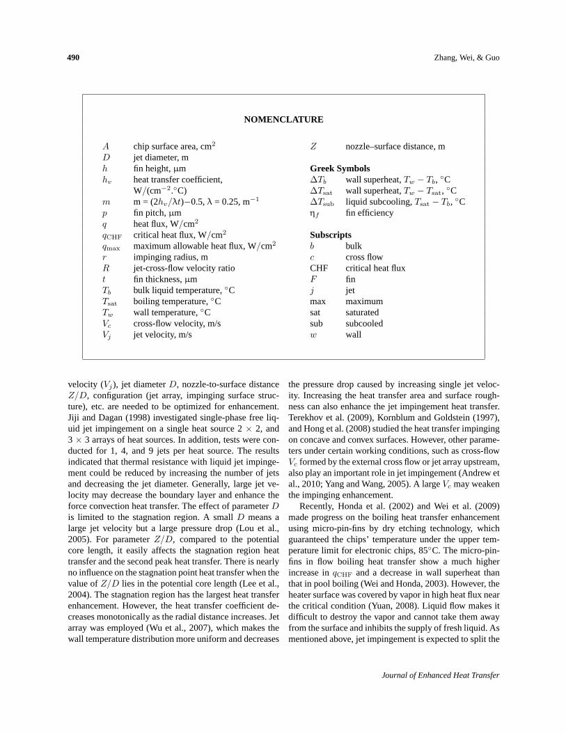
The test facility used for the present study is shownschematically in Fig. 1. It is a closed-loop circuit consist-ing of a tank, a scroll pump, a test section, a jet, two heatexchangers, and two flowmeters. As shown in Fig. 1, thefluid is pumped from the tank to the heat exchanger. Af-ter reaching required liquid temperature, one branch goes
into the test section and the other one impinges on the testchip. Once finishing heat exchange, the fluid goes back tothe tank and begins the next circulation. The pump fre-quency is adjusted to control the mass flow rate and twovalves are regulated to realize different cross-flow or jetvelocities. When the loop reaches a steady state, a directcurrent is initiated to heat the test chip. A short-lived de-lay is imposed before initiating data acquisition to ensuresteady-state conditions. The power input to the test chipis increased in small steps up to the high heat flux regionof nucleate boiling. The heat fluxq is obtained from thevoltage drop of the test chip and the electric current. If thewall temperature increases sharply by more than 20◦C ina short time, the data acquisition algorithm assumes theoccurrence of CHF condition and the power supply is im-mediately shut down. The CHF value is computed as thesteady-state heat flux value just prior to the shutdown ofthe power supply.
FIG. 1: Boiling heat transfer test loop: (1) pump; (2) heat exchanger; (3) flowmeter; (4) test section; (5) direct current;(6) jet; (7) tank; (8) condenser; (9) cooling unit.
Volume 19, Number 6, 2012
492 Zhang, Wei, & Guo
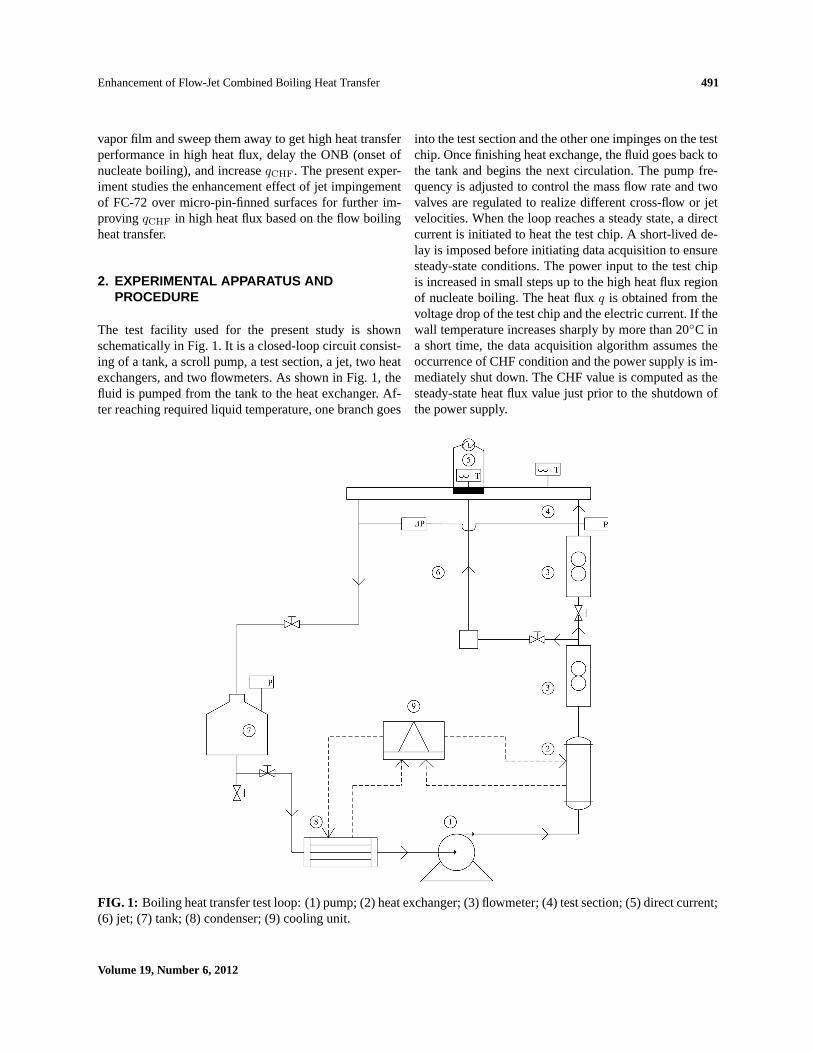
Schematic diagrams of a test section and heater assem-bly are shown in Fig. 2. As shown in Fig. 2(a), the testchip is a P-doped N-type square silicon chip with a sidelength of 10 mm and a thickness of 0.5 mm which is lo-cated 300 mm away from the inlet and is bonded to a sub-strate made of Pyrex glass. The Pyrex glass is fixed onthe bottom of a 5 mm high and 30 mm wide channel. AnO-ring is used to prevent liquid leakage. The jet diameterand nozzle–surface distance are 3 mm and 5 mm, respec-tively. The side surfaces of the chip are covered by adhe-
sive as shown in Fig. 2(b) and thus only the upper surfaceis effective for heat transfer. Two copper wires (0.25 mmdiameter) are soldered on the opposite side surface of thechip for power supply. Two T-type thermocouples with adiameter 0.12 mm for local wall temperatureTw and liq-uid temperatureTb are adhered to the bottom surface atthe center of the chip and located on a vertical line 25 mmaway from the edge of the chip, respectively. Prior to test-ing, the T-type thermocouples for the measurements ofthe liquid and wall temperatures were calibrated against a
(a)
(b)
FIG. 2: Schematic diagrams of test section and heater assembly(a) Test section.(b) Details of heater assembly:(1) O-rings; (2) polycarbonate plate; (3) test chip; (4) copper lead wire; (5) lower cover; (6) upper cover; (7) jet.
Journal of Enhanced Heat Transfer
Enhancement of Flow-Jet Combined Boiling Heat Transfer 493
platinum resistance thermometer (accuracy of±0.03◦C)by using FC-40. A data acquisition unit is connected toa computer, which converts the standard signal (current4∼20 mA) from flowmeter and thermocouples into flowrate and temperature, respectively.
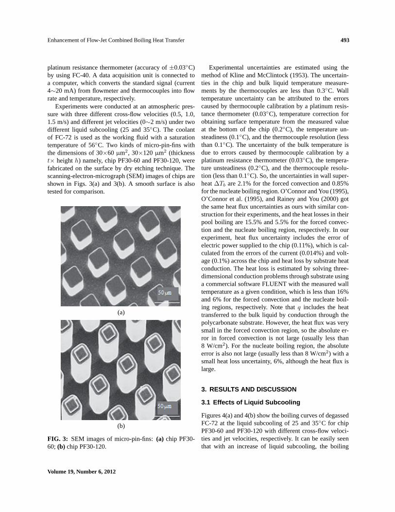
Experiments were conducted at an atmospheric pres-sure with three different cross-flow velocities (0.5, 1.0,1.5 m/s) and different jet velocities (0∼2 m/s) under twodifferent liquid subcooling (25 and 35◦C). The coolantof FC-72 is used as the working fluid with a saturationtemperature of 56◦C. Two kinds of micro-pin-fins withthe dimensions of 30×60 µm2, 30×120µm2 (thicknesst× heighth) namely, chip PF30-60 and PF30-120, werefabricated on the surface by dry etching technique. Thescanning-electron-micrograph (SEM) images of chips areshown in Figs. 3(a) and 3(b). A smooth surface is alsotested for comparison.
(a)
(b)
FIG. 3: SEM images of micro-pin-fins:(a) chip PF30-60; (b) chip PF30-120.
Experimental uncertainties are estimated using themethod of Kline and McClintock (1953). The uncertain-ties in the chip and bulk liquid temperature measure-ments by the thermocouples are less than 0.3◦C. Walltemperature uncertainty can be attributed to the errorscaused by thermocouple calibration by a platinum resis-tance thermometer (0.03◦C), temperature correction forobtaining surface temperature from the measured valueat the bottom of the chip (0.2◦C), the temperature un-steadiness (0.1◦C), and the thermocouple resolution (lessthan 0.1◦C). The uncertainty of the bulk temperature isdue to errors caused by thermocouple calibration by aplatinum resistance thermometer (0.03◦C), the tempera-ture unsteadiness (0.2◦C), and the thermocouple resolu-tion (less than 0.1◦C). So, the uncertainties in wall super-heat∆Tb are 2.1% for the forced convection and 0.85%for the nucleate boiling region. O’Connor and You (1995),O’Connor et al. (1995), and Rainey and You (2000) gotthe same heat flux uncertainties as ours with similar con-struction for their experiments, and the heat losses in theirpool boiling are 15.5% and 5.5% for the forced convec-tion and the nucleate boiling region, respectively. In ourexperiment, heat flux uncertainty includes the error ofelectric power supplied to the chip (0.11%), which is cal-culated from the errors of the current (0.014%) and volt-age (0.1%) across the chip and heat loss by substrate heatconduction. The heat loss is estimated by solving three-dimensional conduction problems through substrate usinga commercial software FLUENT with the measured walltemperature as a given condition, which is less than 16%and 6% for the forced convection and the nucleate boil-ing regions, respectively. Note thatq includes the heattransferred to the bulk liquid by conduction through thepolycarbonate substrate. However, the heat flux was verysmall in the forced convection region, so the absolute er-ror in forced convection is not large (usually less than8 W/cm2). For the nucleate boiling region, the absoluteerror is also not large (usually less than 8 W/cm2) with asmall heat loss uncertainty, 6%, although the heat flux islarge.
3. RESULTS AND DISCUSSION
3.1 Effects of Liquid Subcooling
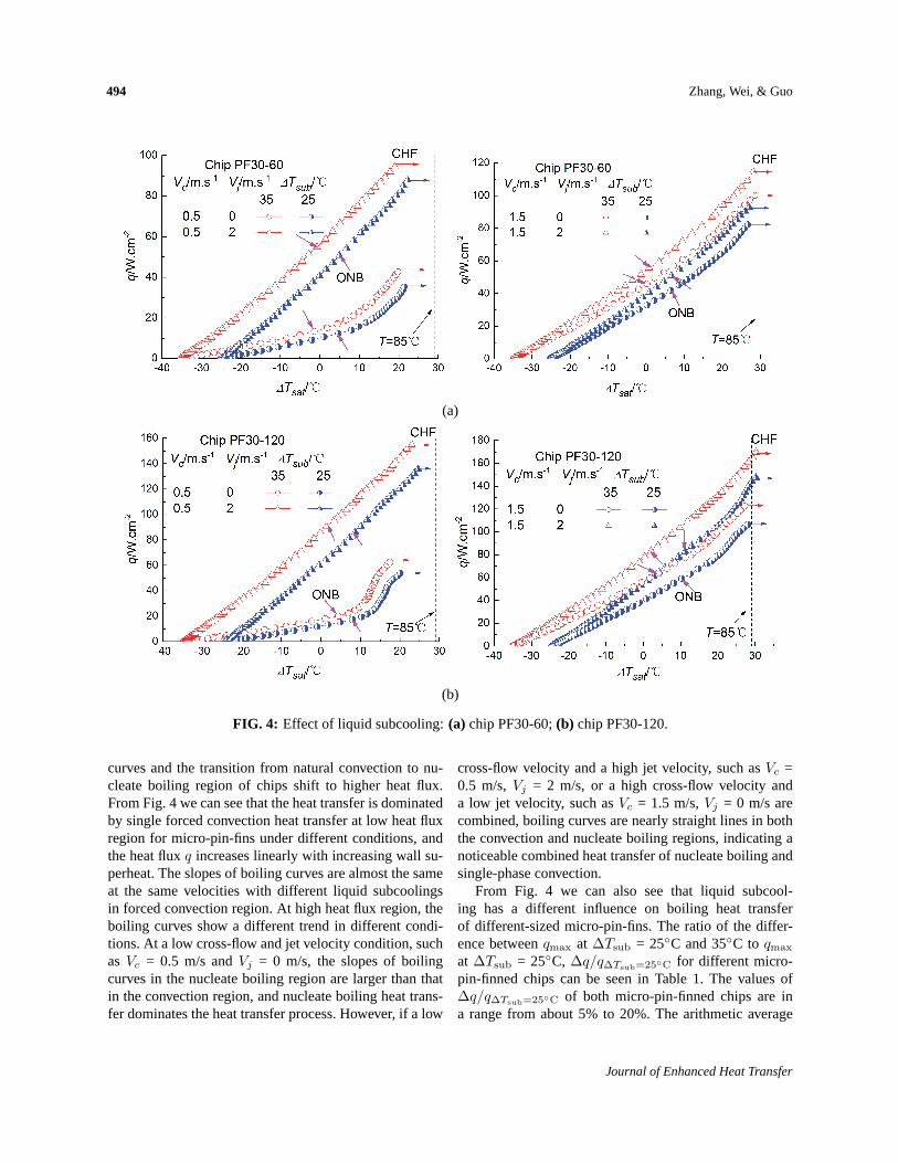
Figures 4(a) and 4(b) show the boiling curves of degassedFC-72 at the liquid subcooling of 25 and 35◦C for chipPF30-60 and PF30-120 with different cross-flow veloci-ties and jet velocities, respectively. It can be easily seenthat with an increase of liquid subcooling, the boiling
Volume 19, Number 6, 2012
494 Zhang, Wei, & Guo
(a)
(b)
FIG. 4: Effect of liquid subcooling:(a) chip PF30-60;(b) chip PF30-120.
curves and the transition from natural convection to nu-cleate boiling region of chips shift to higher heat flux.From Fig. 4 we can see that the heat transfer is dominatedby single forced convection heat transfer at low heat fluxregion for micro-pin-fins under different conditions, andthe heat fluxq increases linearly with increasing wall su-perheat. The slopes of boiling curves are almost the sameat the same velocities with different liquid subcoolingsin forced convection region. At high heat flux region, theboiling curves show a different trend in different condi-tions. At a low cross-flow and jet velocity condition, suchas Vc = 0.5 m/s andVj = 0 m/s, the slopes of boilingcurves in the nucleate boiling region are larger than thatin the convection region, and nucleate boiling heat trans-fer dominates the heat transfer process. However, if a low
cross-flow velocity and a high jet velocity, such asVc =0.5 m/s,Vj = 2 m/s, or a high cross-flow velocity anda low jet velocity, such asVc = 1.5 m/s,Vj = 0 m/s arecombined, boiling curves are nearly straight lines in boththe convection and nucleate boiling regions, indicating anoticeable combined heat transfer of nucleate boiling andsingle-phase convection.
From Fig. 4 we can also see that liquid subcool-ing has a different influence on boiling heat transferof different-sized micro-pin-fins. The ratio of the differ-ence betweenqmax at ∆Tsub = 25◦C and 35◦C to qmax
at ∆Tsub = 25◦C, ∆q/q∆Tsub=25◦C for different micro-pin-finned chips can be seen in Table 1. The values of∆q/q∆Tsub=25◦C of both micro-pin-finned chips are ina range from about 5% to 20%. The arithmetic average
Journal of Enhanced Heat Transfer
Enhancement of Flow-Jet Combined Boiling Heat Transfer 495
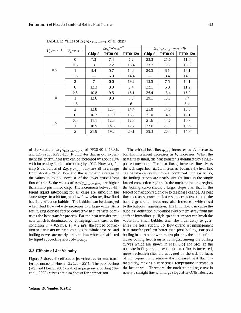
TABLE 1: Values of∆q/q∆Tsub=25◦C of all chips
Vc/m·s−1 Vj/m·s−1 ∆q/W·cm−2 ∆q/q∆Tsub=25◦C/%
Chip S PF30-60 PF30-120 Chip S PF30-60 PF30-120
0.5
0 7.3 7.4 7.2 23.3 21.0 11.6
0.5 8 7.2 13.4 23.7 17.7 18.8
1 8.4 5.7 14.8 20.5 8.1 18.1
1.5 — 5.8 14.4 — 8.4 14.9
2 7 6.6 19.2 13.5 7.5 14.1
1.0
0 12.3 3.9 9.4 32.1 5.8 11.2
0.5 10.8 9.5 13.1 26.4 13.4 13.9
1 12.6 9.8 7.8 29.1 13.1 7.4
1.5 — — 6 — — 5.4
2 13.8 12.4 14.4 25.8 14.0 10.5
1.5
0 10.7 11.9 13.2 21.0 14.5 12.1
0.5 11.1 12.3 12.3 21.6 14.6 10.7
1 16.9 18.3 12.7 32.6 21.1 10.6
2 21.9 19.2 20.1 39.3 20.1 14.3
of the values of∆q/q∆Tsub=25◦C of PF30-60 is 13.8%and 12.4% for PF30-120. It indicates that in our experi-ment the critical heat flux can be increased by about 10%with increasing liquid subcooling by 10◦C. However, forchip S the values of∆q/q∆Tsub=25◦C are all in a rangefrom about 20% to 35% and the arithmetic average ofthe values is 25.7%. Because of the lower critical heatflux of chip S, the values of∆q/q∆Tsub=25◦C are higherthan micro-pin-finned chips. The increments between dif-ferent liquid subcooling for all chips are almost in thesame range. In addition, at a low flow velocity, flow fluidhas little effect on bubbles. The bubbles can be destroyedwhen fluid flow velocity increases to a large value. As aresult, single-phase forced convective heat transfer domi-nates the heat transfer process. For the heat transfer pro-cess which is dominated by jet impingement, such as theconditionVc = 0.5 m/s,Vj = 2 m/s, the forced convec-tion heat transfer nearly dominates the whole process, andboiling curves are nearly straight lines which are affectedby liquid subcooling most obviously.
3.2 Effects of Jet Velocity
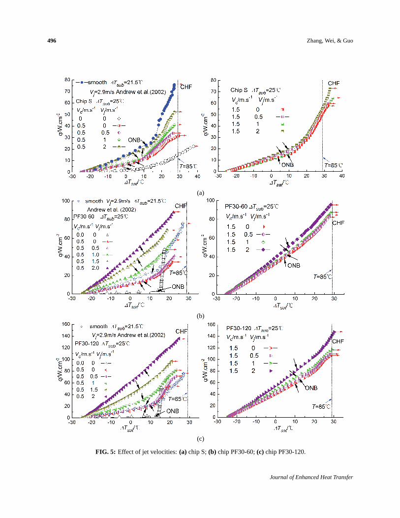
Figure 5 shows the effects of jet velocities on heat trans-fer for micro-pin-fins at∆Tsub = 25◦C. The pool boiling(Wei and Honda, 2003) and jet impingement boiling (Tayet al., 2002) curves are also shown for comparison.
The critical heat fluxqCHF increases asVj increases,but this increment decreases asVc increases. When theheat flux is small, the heat transfer is dominated by single-phase convection. The heat fluxq increases linearly asthe wall superheat∆Tsat increases, because the heat fluxcan be taken away by flow-jet combined fluid easily. So,the boiling curves are nearly straight lines in the singleforced convection region. In the nucleate boiling region,the boiling curve shows a larger slope than that in theforced convection region due to the phase change. As heatflux increases, more nucleate sites are activated and thebubble generation frequency also increases, which leadto the bubbles’ aggregation. The fluid flow can cause thebubbles’ deflection but cannot sweep them away from thesurface immediately. High-speed jet impact can break thevapor into small bubbles and take them away to guar-antee the fresh supply. So, flow or/and jet impingementheat transfer perform better than pool boiling. For poolboiling heat transfer with micro-pin-fins, the slope of nu-cleate boiling heat transfer is largest among the boilingcurves which are shown in Figs. 5(b) and 5(c). In thenucleate boiling region, when the heat flux is increased,more nucleation sites are activated on the side surfacesof micro-pin-fins to remove the increased heat flux im-mediately, making a very small temperature increase inthe heater wall. Therefore, the nucleate boiling curve isnearly a straight line with large slope after ONB. Besides,
Volume 19, Number 6, 2012
496 Zhang, Wei, & Guo
(a)
(b)
(c)
FIG. 5: Effect of jet velocities:(a) chip S;(b) chip PF30-60;(c) chip PF30-120.
Journal of Enhanced Heat Transfer
Enhancement of Flow-Jet Combined Boiling Heat Transfer 497
the micro-pin-fins may be under the thermal boundarylayer and have nearly no enhancement on heat transfer.Fluid flow can decrease the boundary layer and enhancethe heat transfer. The effect of jet velocities on heat trans-fer is complicated and the cross-flow velocities cannot beignored. In the single-phase convection region, the bound-ary layer thickness becomes thinner, which decreases theheat transfer resistance and thus enhances the forced con-vection heat transfer, showing a larger slope as theVc orVj increases. For high heat flux, we can see that the boil-ing curves are greatly affected byVj and the ONB is de-layed with increasingVj . WhenVj is small, flow boilingdominates the heat transfer process, jet flow is bent bycross-flow once it gets into the bulk fluid. There is nearlyno effect on heat transfer. AsVj increases gradually, theimpinged jet flow can penetrate the cross flow and arriveat the surface before leaving the chip, which intensifiesthe microconvection and thus increases the total surfacearea, and a largerqCHF is obtained, but the nucleate boil-ing proportion decreases, showing a small slope, espe-cially for Vc = 0.5 m/s,Vj = 2 m/s. Besides, high-speedimpingement can sweep bubbles away immediately fromthe heater and avoid the secondary nucleation, but it alsocan suppress bubbles’ generation and reduce the stay timeof bubbles, and thus weaken the nucleate boiling. Thebubbles’ detachment from the heater surface can allow thesingle-phase convection to occur because the bubbles areswept and aggregation is downstream, which means thata certain proportion of forced convection exists besidesthe nucleate boiling heat transfer and shows a decrease inslope asVj increases. It indicates that the forced convec-tion heat transfer becomes dominant gradually in the heattransfer process with increasing jet velocity. If the cross-flow velocity or the jet velocity is large enough, the wholeboiling curve is mainly dominated by forced convectionheat transfer and thus is nearly a straight line, such as thecases ofVc = 0.5 m/s,Vj = 2 m/s, orVc = 1.5 m/s,Vj =0 m/s.
However, the enhancement degrees for different sur-face structures are different. Chips PF30-60 and PF30-120 show a better heat transfer enhancement comparedwith smooth surface due to an increase in total heat trans-fer surface area. The optimum fin heighth and fin gappare determined by the balance between the capillary forceand the flow resistance for microconvection. So, the pa-rameters of the ratio of fin height to fin pitchh/p andvelocity Vc(Vj) become the main influencing factors onheat transfer enhancement. The nucleation on the heatersurface is more easily affected by the flow whenh/p issmall or/andVc(Vj) is large, and thus prevents the burst
of nucleate bubbles and reduces the proportion of nucleateboiling. Theh/p values for chip PF30-60 and chip PF30-120 are 1 and 2, respectively, so chip PF30-120 is lessaffected by the flow velocity than chip PF30-60, showinga larger slope. AtVc = 0.5 m/s,Vj = 2 m/s condition, theslope of the nucleate boiling region is larger than otherconditions and nearly the same as that of the forced con-vection region, which indicates that the forced convectionheat transfer dominates the heat transfer process in thehigh heat flux region. However, small cross-flow veloc-ity cannot sweep the bubbles away from the heat surfaceimmediately and block the supply of fresh liquid, so al-though the enhancement is large forVc = 0.5 m/s,Vj =2 m/s, the critical wall superheat is lower than that forlargeVc (1.5 m/s) whenVj = 2 m/s.
3.3 Effects of Jet-Cross-Flow Velocity Ratio
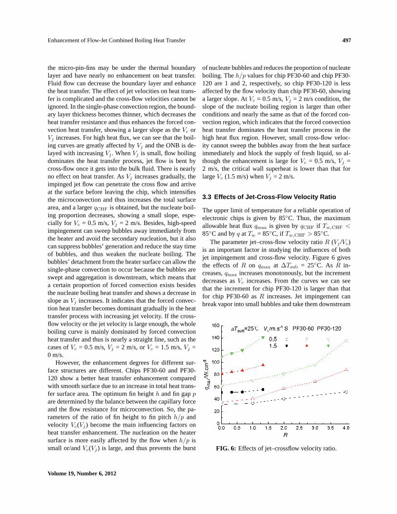
The upper limit of temperature for a reliable operation ofelectronic chips is given by 85◦C. Thus, the maximumallowable heat fluxqmax is given byqCHF if Tw,CHF <85◦C and byq atTw = 85◦C, if Tw,CHF > 85◦C.
The parameter jet–cross-flow velocity ratioR (Vj /Vc)is an important factor in studying the influences of bothjet impingement and cross-flow velocity. Figure 6 givesthe effects ofR on qmax at ∆Tsub = 25◦C. As R in-creases,qmax increases monotonously, but the incrementdecreases asVc increases. From the curves we can seethat the increment for chip PF30-120 is larger than thatfor chip PF30-60 asR increases. Jet impingement canbreak vapor into small bubbles and take them downstream
FIG. 6: Effects of jet–crossflow velocity ratio.
Volume 19, Number 6, 2012
498 Zhang, Wei, & Guo
and thus improveqmax. The influences of fluid flow onboiling heat transfer are affected by the bubbles’ gener-ation and movement due to the different fin sizes. Gen-erally, large fin height has a large flow resistance for mi-croconvection, which decreases the fin efficiency. AsVj
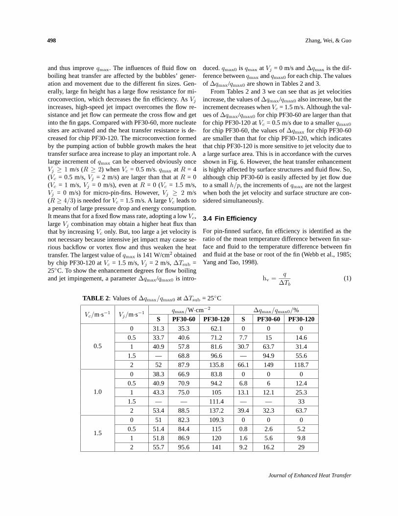
increases, high-speed jet impact overcomes the flow re-sistance and jet flow can permeate the cross flow and getinto the fin gaps. Compared with PF30-60, more nucleatesites are activated and the heat transfer resistance is de-creased for chip PF30-120. The microconvection formedby the pumping action of bubble growth makes the heattransfer surface area increase to play an important role. Alarge increment ofqmax can be observed obviously onceVj ≥ 1 m/s (R ≥ 2) whenVc = 0.5 m/s.qmax at R = 4(Vc = 0.5 m/s,Vj = 2 m/s) are larger than that atR = 0(Vc = 1 m/s,Vj = 0 m/s), even atR = 0 (Vc = 1.5 m/s,Vj = 0 m/s) for micro-pin-fins. However,Vj ≥ 2 m/s(R ≥ 4/3) is needed forVc = 1.5 m/s. A largeVc leads toa penalty of large pressure drop and energy consumption.It means that for a fixed flow mass rate, adopting a lowVc,largeVj combination may obtain a higher heat flux thanthat by increasingVc only. But, too large a jet velocity isnot necessary because intensive jet impact may cause se-rious backflow or vortex flow and thus weaken the heattransfer. The largest value ofqmax is 141 W/cm2 obtainedby chip PF30-120 atVc = 1.5 m/s,Vj = 2 m/s,∆Tsub =25◦C. To show the enhancement degrees for flow boilingand jet impingement, a parameter∆qmax/qmax0 is intro-
duced.qmax0 is qmax atVj = 0 m/s and∆qmax is the dif-ference betweenqmax andqmax0 for each chip. The valuesof ∆qmax/qmax0 are shown in Tables 2 and 3.
From Tables 2 and 3 we can see that as jet velocitiesincrease, the values of∆qmax/qmax0 also increase, but theincrement decreases whenVc = 1.5 m/s. Although the val-ues of∆qmax/qmax0 for chip PF30-60 are larger than thatfor chip PF30-120 atVc = 0.5 m/s due to a smallerqmax0
for chip PF30-60, the values of∆qmax for chip PF30-60are smaller than that for chip PF30-120, which indicatesthat chip PF30-120 is more sensitive to jet velocity due toa large surface area. This is in accordance with the curvesshown in Fig. 6. However, the heat transfer enhancementis highly affected by surface structures and fluid flow. So,although chip PF30-60 is easily affected by jet flow dueto a smallh/p, the increments ofqmax are not the largestwhen both the jet velocity and surface structure are con-sidered simultaneously.
3.4 Fin Efficiency
For pin-finned surface, fin efficiency is identified as theratio of the mean temperature difference between fin sur-face and fluid to the temperature difference between finand fluid at the base or root of the fin (Webb et al., 1985;Yang and Tao, 1998).
hv =q
∆Tb(1)
TABLE 2 : Values of∆qmax/qmax0 at∆Tsub = 25◦C
Vc/m·s−1 Vj/m·s−1 qmax/W·cm−2 ∆qmax/qmax0/%
S PF30-60 PF30-120 S PF30-60 PF30-120
0.5
0 31.3 35.3 62.1 0 0 0
0.5 33.7 40.6 71.2 7.7 15 14.6
1 40.9 57.8 81.6 30.7 63.7 31.4
1.5 — 68.8 96.6 — 94.9 55.6
2 52 87.9 135.8 66.1 149 118.7
1.0
0 38.3 66.9 83.8 0 0 0
0.5 40.9 70.9 94.2 6.8 6 12.4
1 43.3 75.0 105 13.1 12.1 25.3
1.5 — — 111.4 — — 33
2 53.4 88.5 137.2 39.4 32.3 63.7
1.5
0 51 82.3 109.3 0 0 0
0.5 51.4 84.4 115 0.8 2.6 5.2
1 51.8 86.9 120 1.6 5.6 9.8
2 55.7 95.6 141 9.2 16.2 29
Journal of Enhanced Heat Transfer

Enhancement of Flow-Jet Combined Boiling Heat Transfer 499
TABLE 3: Values of∆qmax/qmax0 at∆Tsub = 35◦C
Vc/m·s−1 Vj/m·s−1 qmax/W·cm−2 ∆qmax/qmax0/%
S PF30-60 PF30-120 S PF30-60 PF30-120
0.5
0 38.6 42.7 69.3 0 0 0
0.5 41.7 47.8 84.6 8 11.9 22.1
1 49.3 62.5 96.4 27.7 46.4 39.1
1.5 — 74.6 111 — 74.7 60.2
2 59 94.5 155 52.8 121.3 123.7
1.0
0 50.6 70.8 93.2 0 0 0
0.5 51.7 80.4 107.3 2.2 13.6 15.1
1 55.9 84.8 112.8 10.5 19.8 21
1.5 — — 117.4 — — 26
2 67.2 100.9 151.6 32.8 42.5 62.7
1.5
0 61.7 94.2 122.5 0 0 0
0.5 62.5 96.7 127.3 1.3 2.7 3.9
1 68.7 105.2 132.7 11.3 11.7 8.3
2 77.6 114.8 161.0 25.8 21.9 31.5
ηf =tanh [m (h+ t/2)]
m (h+ t/2)(2)
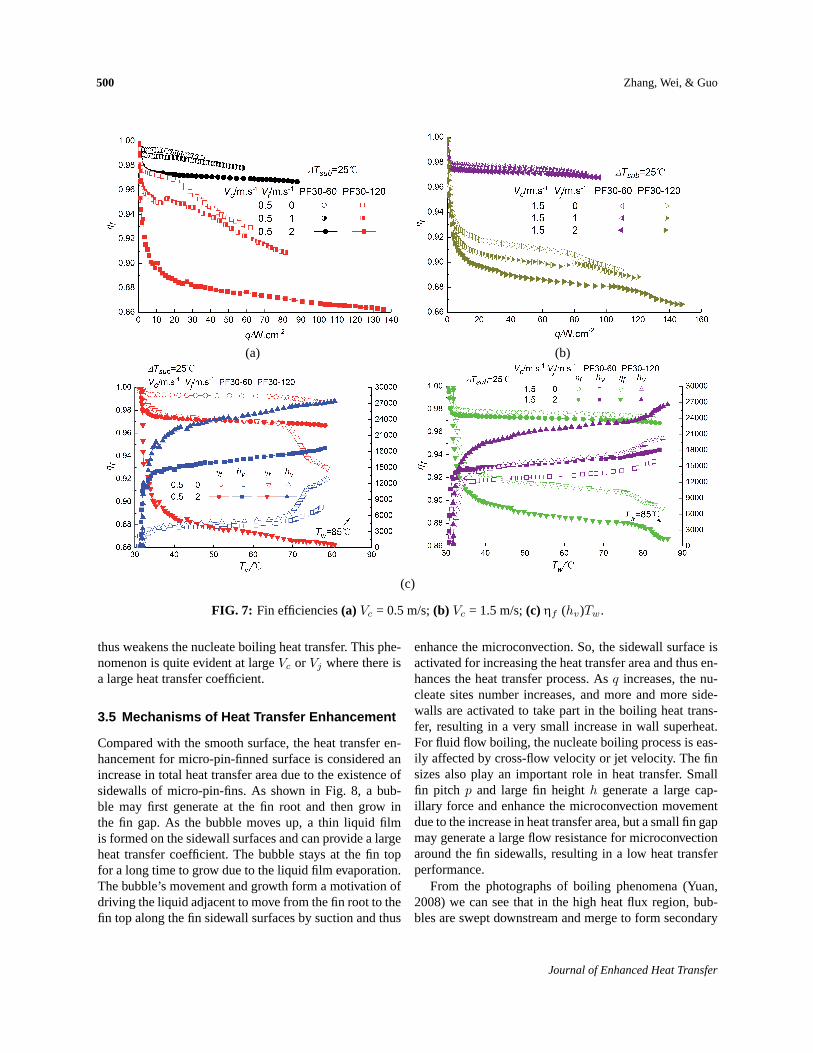
Figures 7(a) and 7(b) show the fin efficiencies versusheat flux for different micro-pin-fins at the liquid subcool-ing of 25◦C and Fig. 7(c) shows fin efficiencies and heattransfer coefficient distribution versus wall temperatureTw at the same liquid subcooling. As shown in Figs. 7(a)and 7(b), the fin efficiencyηf decreases as the heat fluxq increases. A largeVj leads to a smallηf for a fixedVc, but theηf differences between differentVj decreaseasVc increases. As is well known, nucleate boiling is themost efficient way of heat transfer. For micro-pin-fins, thenucleate boiling process is highly affected by flow fieldand fin sizes. The heat transfer enhancement for micro-pin-fins is due to an increase in total surface area. Fluidflow can decrease the boundary layer and sweep bubblesaway downstream and thus guarantee the fresh liquid sup-ply to the heat surface. From Fig. 7(c), we can see that asthe wall temperatureTw increases,hv which is obtainedfrom Eq. (1) also increases butηf decreases. As heat fluxq increases, the number of nucleate sites increases and themicroconvection movement is intensified, which leads toa large heat transfer coefficient and a small wall super-heat increase. However, according to Eq. (2), a large heattransfer coefficienthv means a low fin efficiencyηf . Thelowestηf is obtained atVc = 0.5 m/s,Vj = 2 m/s. In the
nucleate boiling region shown in Fig. 5 the boiling curvesare very steep, which indicates that there is a small in-crease inTw. The differences betweenTw andTb becomesmaller asVc orVj increases for a fixed heat flux, decreas-ing the driving force for heat transfer, sohv increases butηf decreases. Generally for a given heat flux,ηf of chipPF30-60 is larger than that of chip PF30-120. So, chipPF30-120 shows better heat transfer performances thanchip PF30-60, with a largerhv and thus a lowerηf . Com-pared with a fin heighth of 60µm, a fin height of 120µmhas a large resistance, including the flow resistance offresh liquid supply and the resistance of microconvec-tion. Although the micro-pin-fins can make the bubblesstay at the top surface for a long time to grow, a large finheight causes a large resistance for the bubbles’ detach-ment. However, theqCHF of chip PF30-120 with largerfin height also has a much larger heat transfer surfacearea than that of chip PF30-60. The ratios of micro-pin-finned surface area to smooth surface area are 3.0 and 5.0for chips PF30-60 and PF30-120, respectively. Here, thedominant factor of the enhancement of boiling heat trans-fer is the heat transfer surface area rather than the flowresistance for the microconvection, and thus the experi-mental results show that the increase of fin height causesthe improvedqCHF. Furthermore, the temperature at thefin top surface is lower than that at the fin root. The driv-ing force of boiling and bubbles’ growth decreases and
Volume 19, Number 6, 2012
500 Zhang, Wei, & Guo
(a) (b)
(c)
FIG. 7: Fin efficiencies(a) Vc = 0.5 m/s;(b) Vc = 1.5 m/s;(c) ηf (hv)Tw.
thus weakens the nucleate boiling heat transfer. This phe-nomenon is quite evident at largeVc or Vj where there isa large heat transfer coefficient.
3.5 Mechanisms of Heat Transfer Enhancement
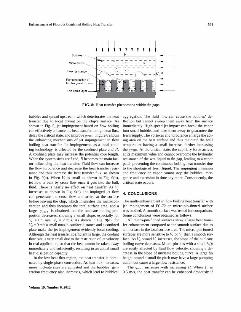
Compared with the smooth surface, the heat transfer en-hancement for micro-pin-finned surface is considered anincrease in total heat transfer area due to the existence ofsidewalls of micro-pin-fins. As shown in Fig. 8, a bub-ble may first generate at the fin root and then grow inthe fin gap. As the bubble moves up, a thin liquid filmis formed on the sidewall surfaces and can provide a largeheat transfer coefficient. The bubble stays at the fin topfor a long time to grow due to the liquid film evaporation.The bubble’s movement and growth form a motivation ofdriving the liquid adjacent to move from the fin root to thefin top along the fin sidewall surfaces by suction and thus
enhance the microconvection. So, the sidewall surface isactivated for increasing the heat transfer area and thus en-hances the heat transfer process. Asq increases, the nu-cleate sites number increases, and more and more side-walls are activated to take part in the boiling heat trans-fer, resulting in a very small increase in wall superheat.For fluid flow boiling, the nucleate boiling process is eas-ily affected by cross-flow velocity or jet velocity. The finsizes also play an important role in heat transfer. Smallfin pitch p and large fin heighth generate a large cap-illary force and enhance the microconvection movementdue to the increase in heat transfer area, but a small fin gapmay generate a large flow resistance for microconvectionaround the fin sidewalls, resulting in a low heat transferperformance.
From the photographs of boiling phenomena (Yuan,2008) we can see that in the high heat flux region, bub-bles are swept downstream and merge to form secondary
Journal of Enhanced Heat Transfer
Enhancement of Flow-Jet Combined Boiling Heat Transfer 501
FIG. 8: Heat transfer phenomena within fin gaps
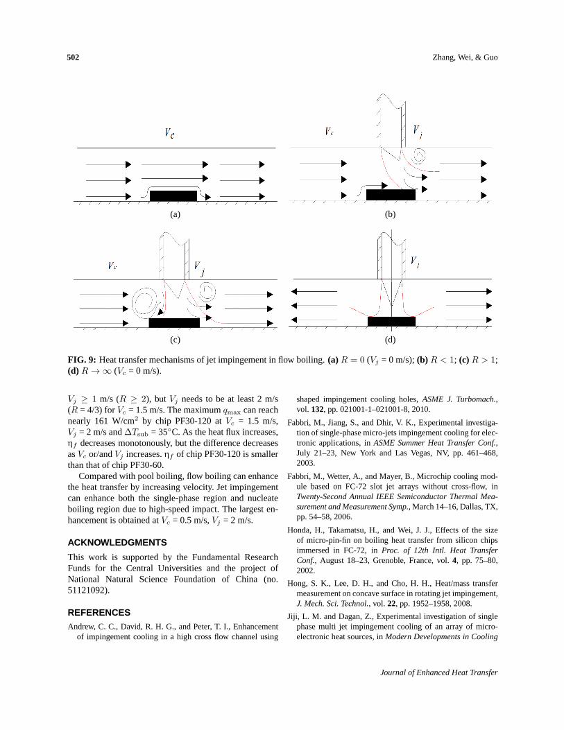
bubbles and spread upstream, which deteriorates the heattransfer due to local dryout on the chip’s surface. Asshown in Fig. 5, jet impingement based on flow boilingcan effectively enhance the heat transfer in high heat flux,delay the critical state, and improveqCHF. Figure 8 showsthe enhancing mechanisms of jet impingement in flowboiling heat transfer. Jet impingement, as a local cool-ing technology, is affected by the confined plate andR.A confined plate may increase the potential core length.When the system sizes are fixed,R becomes the main fac-tor influencing the heat transfer. Fluid flow can increasethe flow turbulence and decrease the heat transfer resis-tance and thus increase the heat transfer flux, as shownin Fig. 9(a). WhenVj is small as shown in Fig. 9(b),jet flow is bent by cross flow once it gets into the bulkfluid. There is nearly no effect on heat transfer. AsVj
increases as shown in Fig. 9(c), the impinged jet flowcan penetrate the cross flow and arrive at the surfacebefore leaving the chip, which intensifies the microcon-vection and thus increases the total surface area, and alarger qCHF is obtained, but the nucleate boiling pro-portion decreases, showing a small slope, especially forVc = 0.5 m/s,Vj = 2 m/s. As shown in Fig. 9(d), forVc = 0 m/s a small nozzle–surface distance and a confinedplate make the jet impingement evidently local cooling.Although the heat transfer coefficient is large, the coolantflow rate is very small due to the restriction of jet velocityin real application, so that the heat cannot be taken awayimmediately and sufficiently, resulting in an actual smallheat dissipation capacity.
In the low heat flux region, the heat transfer is domi-nated by single-phase convection. As heat flux increases,more nucleate sites are activated and the bubbles’ gen-eration frequency also increases, which lead to bubbles’
aggregation. The fluid flow can cause the bubbles’ de-flection but cannot sweep them away from the surfaceimmediately. High-speed jet impact can break the vaporinto small bubbles and take them away to guarantee thefresh supply. The vortexes and turbulence enlarge the act-ing area on the heat surface and thus maintain the walltemperature having a small increase, further increasingtheqCHF. At the critical state, the capillary force arrivesat its maximum value and cannot overcome the hydraulicresistance of the wet liquid to fin gap, leading to a vaporpatch preventing the continuous boiling heat transfer dueto the shortage of fresh liquid. The impinging intensionand frequency on vapor cannot stop the bubbles’ mer-gence and extension in time any more. Consequently, thecritical state occurs.
4. CONCLUSIONS
The multi-enhancement in flow boiling heat transfer withjet impingement of FC-72 on micro-pin-finned surfacewas studied. A smooth surface was tested for comparison.Some conclusions were obtained as follows:
All micro-pin-finned surfaces show a large heat trans-fer enhancement compared to the smooth surface due toan increase in the total surface area. The micro-pin-finnedsurfaces are more sensitive toVc or Vj than a smooth sur-face. AsVc or/andVj increases, the slope of the nucleateboiling curve decreases. Micro-pin-fins with a smallh/pare easily affected by fluid flow velocity, showing a de-crease in the slope of nucleate boiling curve. A large finheight or/and a small fin pitch may have a large pumpingaction but cause a large flow resistance.
The qmax increases with increasingR. When Vc is0.5 m/s, the heat transfer can be enhanced obviously if
Volume 19, Number 6, 2012
502 Zhang, Wei, & Guo
(a) (b)
(c) (d)
FIG. 9: Heat transfer mechanisms of jet impingement in flow boiling.(a)R = 0 (Vj = 0 m/s);(b) R < 1; (c)R > 1;(d) R → ∞ (Vc = 0 m/s).
Vj ≥ 1 m/s (R ≥ 2), but Vj needs to be at least 2 m/s(R = 4/3) forVc = 1.5 m/s. The maximumqmax can reachnearly 161 W/cm2 by chip PF30-120 atVc = 1.5 m/s,Vj = 2 m/s and∆Tsub = 35◦C. As the heat flux increases,ηf decreases monotonously, but the difference decreasesasVc or/andVj increases.ηf of chip PF30-120 is smallerthan that of chip PF30-60.
Compared with pool boiling, flow boiling can enhancethe heat transfer by increasing velocity. Jet impingementcan enhance both the single-phase region and nucleateboiling region due to high-speed impact. The largest en-hancement is obtained atVc = 0.5 m/s,Vj = 2 m/s.
ACKNOWLEDGMENTS
This work is supported by the Fundamental ResearchFunds for the Central Universities and the project ofNational Natural Science Foundation of China (no.51121092).
REFERENCESAndrew, C. C., David, R. H. G., and Peter, T. I., Enhancement
of impingement cooling in a high cross flow channel using
shaped impingement cooling holes,ASME J. Turbomach.,vol. 132, pp. 021001-1–021001-8, 2010.
Fabbri, M., Jiang, S., and Dhir, V. K., Experimental investiga-tion of single-phase micro-jets impingement cooling for elec-tronic applications, inASME Summer Heat Transfer Conf.,July 21–23, New York and Las Vegas, NV, pp. 461–468,2003.
Fabbri, M., Wetter, A., and Mayer, B., Microchip cooling mod-ule based on FC-72 slot jet arrays without cross-flow, inTwenty-Second Annual IEEE Semiconductor Thermal Mea-surement and Measurement Symp., March 14–16, Dallas, TX,pp. 54–58, 2006.
Honda, H., Takamatsu, H., and Wei, J. J., Effects of the sizeof micro-pin-fin on boiling heat transfer from silicon chipsimmersed in FC-72, inProc. of 12th Intl. Heat TransferConf., August 18–23, Grenoble, France, vol.4, pp. 75–80,2002.
Hong, S. K., Lee, D. H., and Cho, H. H., Heat/mass transfermeasurement on concave surface in rotating jet impingement,J. Mech. Sci. Technol., vol. 22, pp. 1952–1958, 2008.
Jiji, L. M. and Dagan, Z., Experimental investigation of singlephase multi jet impingement cooling of an array of micro-electronic heat sources, inModern Developments in Cooling
Journal of Enhanced Heat Transfer
Enhancement of Flow-Jet Combined Boiling Heat Transfer 503
Technology for Electronic Equipment, W. Aung, ed., Hemi-sphere Publishing, New York, pp. 265–283, 1998.
Kline, S. J. and McClintock, F. A., Describing uncertainties insingle-sample experiments,Am. Soc. Mech. Eng., vol. 75, pp.3–8, 1953.
Kornblum, Y. and Goldstein, R. J., Jet impingement on semi-circular concave and convex surface: Heat transfer, inProc.of Intl. Symposium: Physics of Heat Transfer in Boiling andCondensation, March 14–16, Moscow, Russia, pp. 603–608,1997.
Lee, D. H., Song, J., and Myeong, C. J., The effects of nozzlediameter on impinging heat transfer and fluid flow,ASME J.Heat Transfer, vol. 126, pp. 554–557, 2004.
Lou, Z. Q., Mujundar, A. S., and Yap, C., Effects of geomet-ric parameters on confined impinging jet heat transfer,Appl.Therm. Eng., vol. 25, pp. 2687–2697, 2005.
Ma, C. F. and Bergles, A. E., Boiling jet impingement of sim-ulated microelectronic chips,ASME HTD, vol. 28, pp. 5–12,1983.
Nguyen, C. T., Galanis, N., and Polidori, G., An experimentalstudy of a confined and submerged impinging jet heat transferusing Al2O3-water nanofluid.Int. J. Therm. Sci., vol. 48, pp.401–411, 2009.
O’Connor, J. P. and You, S. M., A painting technique to enhancepool boiling heat transfer in FC-72,ASME J. Heat Transfer,vol. 117, pp. 387–393, 1995.
O’Connor, J. P., You, S. M., and Chang, J. Y., Gas saturated poolboiling heat transfer from smooth and micro-porous surfacesin FC-72, ASME J. Heat Transfer, vol. 118, pp. 662–667,1995.
Rainey, K. N. and You, S. M., Pool boiling heat transfer fromplain and micro-porous, square pin-finned surfaces in satu-rated FC-72,ASME J. Heat Transfer, vol. 122, pp. 509–516,2000.
Tay, A. A. O., Hong, X., and Cheng, Y., Cooling of electronics
components with free jet impingement boiling,Intel. Soc.Conf. on Thermal Phenomena, May 30–June 1, Jeju Island,South Korea, vol.6, pp. 387–394, 2002.
Terekhov, V. I., Kalinina, S. V., and Mshvidobadze, Y. M., Im-pingement of an impact jet onto spherical cavity: Flow struc-ture and heat transfer,Int. J. Heat Mass Transfer, vol. 52, pp.2498–2506, 2009.
Webb, R. L., Rudy, R. M., and Kedzierski, M. A., Prediction ofthe condensation coefficient on horizontal integral-fin tubes,Int. J. Heat Transfer, vol. 107, pp. 368–376, 1985.
Wei, J. J. and Honda, H., Effects of fin geometry on boiling heattransfer from silicon chips with micro-pin-fins immersed inFC-72, Int. J. Heat Mass Transfer, vol. 46, pp. 4059–4070,2003.
Wei, J. J., Guo, L. J., and Honda, H., Experimental study ofboiling phenomena and heat transfer performances of FC-72over micro-pin-finned silicon chips,Heat Mass Transfer, vol.41, pp. 744–755, 2009.
Wei, J. J., Zhao, J. F., and Yuan, M. Z., Boiling heat transferenhancement by using micro-pin-finned surface for electron-ics cooling,Microgravity Sci. Technol. (suppl 1), vol. 21, pp.159–173, 2009.
Wu, S. J., Shin, C. H., and Kim, K. M., Single-phase convectionand boiling heat transfer: Confined single and array-circularimpinging jets,Int. J. Multiphase Flow, vol. 33, pp. 1271–1283, 2007.
Yang, S. M. and Tao, W. Q.,Heat Transfer (Third Section), Bei-jing: Higher Education Press, China, 1998.
Yang, Y. T. and Wang, Y. X., Three-dimensional numerical sim-ulation of an inclined jet with cross-flow,Int. J. Heat MassTransfer, vol. 48, pp. 4019–4027, 2005.
Yuan, M. Z., Experimental study of enhanced flow boiling heattransfer for high-efficient cooling of electronic components,Xi’an: School of Energy and Power Engineering, Xi’an Jiao-tong University, 2008.
Volume 19, Number 6, 2012
![Flow boiling heat transfer of HFO1234yf and HFC32 ... boiling heat transfer of... · boiling heat transfer coefficient is calculated from the pool boiling correlation of Cooper [7].](https://static.fdocuments.in/doc/165x107/6060f16e796df51c036c4972/flow-boiling-heat-transfer-of-hfo1234yf-and-hfc32-boiling-heat-transfer-of.jpg)